

Page 1

SITRANS P
Pressure transmitter
SITRANS P320/P420 with 4 to 20
mA/HART
7MF03..-.....-.... (SITRANS P320)
7MF04..-.....-.... (SITRANS P420)
Getting started
1
Compact Operating Instructions
Introduction
Safety instructions
Installing/mounting
Connecting
Commissioning
Service and maintenance
Technical data
2
3
4
5
6
7
8
Appendix A
A
09/2018
A5E38874562-AB
Page 2

Legal information
Warning notice system
This manual contains notices you have to observe in order to ensure your personal safety, as well as to prevent
damage to property. The notices referring to your personal safety are highlighted in the manual by a safety alert
symbol, notices referring only to property damage have no safety alert symbol. These notices shown below are
graded according to the degree of danger.
DANGER
indicates that death or severe personal injury will result if proper precautions are not taken.
WARNING
indicates that death or severe personal injury may result if proper precautions are not taken.
CAUTION
indicates that minor personal injury can result if proper precautions are not taken.
NOTICE
indicates that property damage can result if proper precautions are not taken.
If more than one degree of danger is present, the warning notice representing the highest degree of danger will be
used. A notice warning of injury to persons with a safety alert symbol may also include a warning relating to property
damage.
Qualified Personnel
The product/system described in this documentation may be operated only by personnel qualified for the specific
task in accordance with the relevant documentation, in particular its warning notices and safety instructions. Qualified
personnel are those who, based on their training and experience, are capable of identifying risks and avoiding
potential hazards when working with these products/systems.
Proper use of Siemens products
Note the following:
WARNING
Siemens products may only be used for the applications described in the catalog and in the relevant technical
documentation. If products and components from other manufacturers are used, these must be recommended or
approved by Siemens. Proper transport, storage, installation, assembly, commissioning, operation and
maintenance are required to ensure that the products operate safely and without any problems. The permissible
ambient conditions must be complied with. The information in the relevant documentation must be observed.
Trademarks
All names identified by ® are registered trademarks of Siemens AG. The remaining trademarks in this publication
may be trademarks whose use by third parties for their own purposes could violate the rights of the owner.
Disclaimer of Liability
We have reviewed the contents of this publication to ensure consistency with the hardware and software described.
Since variance cannot be precluded entirely, we cannot guarantee full consistency. However, the information in
this publication is reviewed regularly and any necessary corrections are included in subsequent editions.
Siemens AG
Division Process Industries and Drives
Postfach 48 48
90026 NÜRNBERG
GERMANY
Document order number: A5E38874562
Ⓟ 09/2018 Subject to change
Copyright © Siemens AG 2018.
All rights reserved
Page 3

Table of contents
1 Getting started..............................................................................................................................................7
1.1 Commissioning the device without display...............................................................................7
1.2 Commissioning the device with display....................................................................................8
2 Introduction.................................................................................................................................................11
2.1 Purpose of this documentation...............................................................................................11
2.2 Document history...................................................................................................................11
2.3 Scope of validity of this document..........................................................................................11
2.4 Intended use..........................................................................................................................12
2.5 Product compatibility..............................................................................................................13
2.6 Nameplate layout...................................................................................................................14
2.7 Checking the consignment.....................................................................................................16
2.8 Security information...............................................................................................................16
2.9 Transportation and storage....................................................................................................17
2.10 Notes on warranty..................................................................................................................17
3 Safety instructions......................................................................................................................................19
3.1 Precondition for use...............................................................................................................19
3.1.1 Warning symbols on the device.............................................................................................19
3.1.2 Laws and directives................................................................................................................19
3.1.3 Conformity with European directives......................................................................................20
3.2 Requirements for special applications...................................................................................20
3.3 Use in hazardous areas.........................................................................................................21
4 Installing/mounting......................................................................................................................................23
4.1 Basic safety instructions.........................................................................................................23
4.1.1 Installation location requirements...........................................................................................26
4.1.1.1 Devices with marine approval................................................................................................26
4.1.2 Proper mounting.....................................................................................................................27
4.2 Installation (except level)........................................................................................................27
4.2.1 Installation configuration........................................................................................................27
4.2.2 Installation (except level)........................................................................................................28
4.2.3 Fastening with the mounting bracket.....................................................................................29
4.3 Installation (level)...................................................................................................................30
4.3.1 Mounting on the container......................................................................................................31
4.4 Removing...............................................................................................................................35
SITRANS P320/P420 with 4 to 20 mA/HART
Compact Operating Instructions, 09/2018, A5E38874562-AB 3
Page 4

Table of contents
5 Connecting.................................................................................................................................................37
5.1 Basic safety instructions.........................................................................................................37
5.2 Connecting the device............................................................................................................41
5.2.1 Opening the device................................................................................................................41
5.2.2 Connecting the device............................................................................................................42
5.2.3 Closing the device..................................................................................................................43
6 Commissioning...........................................................................................................................................45
6.1 Basic safety instructions.........................................................................................................45
6.2 Switching on the supply voltage.............................................................................................46
6.3 Commissioning the device.....................................................................................................47
6.4 gauge pressure, absolute pressure from the differential pressure series and absolute
pressure from the gauge pressure series..............................................................................47
6.4.1 Commissioning for gases.......................................................................................................47
6.4.2 Commissioning with steam or liquid.......................................................................................49
6.5 Differential pressure and flow rate.........................................................................................50
6.5.1 Commissioning in gaseous environments..............................................................................50
6.5.2 Commissioning for liquids......................................................................................................52
6.5.3 Commissioning with vapor.....................................................................................................53
7 Service and maintenance...........................................................................................................................57
7.1 Basic safety instructions.........................................................................................................57
7.2 Cleaning.................................................................................................................................58
7.2.1 Servicing the remote seal measuring system........................................................................58
7.3 Maintenance and repair work.................................................................................................58
7.3.1 Defining the maintenance interval..........................................................................................59
7.3.2 Checking the gaskets.............................................................................................................60
7.3.3 Diagnostics messages...........................................................................................................61
7.4 Return procedure...................................................................................................................61
7.5 Disposal.................................................................................................................................61
8 Technical data............................................................................................................................................63
8.1 Input.......................................................................................................................................63
8.1.1 Gauge pressure.....................................................................................................................63
8.1.2 Gauge pressure with front-flush diaphragm...........................................................................64
8.1.3 Gauge pressure from the differential pressure series............................................................65
8.1.4 Absolute pressure from the gauge pressure series...............................................................66
8.1.5 Absolute pressure with front-flush diaphragm........................................................................67
8.1.6 Absolute pressure from the differential pressure series.........................................................68
8.1.7 Differential pressure and flow.................................................................................................69
8.1.8 Level.......................................................................................................................................70
8.2 Measuring accuracy of SITRANS P320.................................................................................71
8.2.1 Reference conditions.............................................................................................................71
8.2.2 Effect of auxiliary power supply..............................................................................................71
8.2.3 Gauge pressure.....................................................................................................................71
8.2.4 Gauge pressure from the differential pressure series............................................................73
SITRANS P320/P420 with 4 to 20 mA/HART
4 Compact Operating Instructions, 09/2018, A5E38874562-AB
Page 5

Table of contents
8.2.5 Absolute pressure from gauge and differential pressure series.............................................74
8.2.6 Absolute pressure with front-flush diaphragm........................................................................75
8.2.7 Gauge pressure with front-flush diaphragm...........................................................................76
8.2.8 Differential pressure and flow.................................................................................................77
8.2.9 Level.......................................................................................................................................80
8.3 Measuring accuracy of SITRANS P420.................................................................................81
8.3.1 Reference conditions.............................................................................................................81
8.3.2 Effect of auxiliary power supply..............................................................................................81
8.3.3 Gauge pressure.....................................................................................................................81
8.3.4 Gauge pressure from the differential pressure series ...........................................................82
8.3.5 Absolute pressure from gauge and differential pressure series.............................................84
8.3.6 Absolute pressure with front-flush diaphragm........................................................................85
8.3.7 Gauge pressure with front-flush diaphragm...........................................................................86
8.3.8 Differential pressure and flow.................................................................................................86
8.3.9 Level.......................................................................................................................................90
8.4 Operating conditions..............................................................................................................91
8.5 Vibration resistance................................................................................................................95
8.6 Construction...........................................................................................................................97
8.7 Torques................................................................................................................................101
8.8 Display, keyboard and auxiliary power.................................................................................101
8.9 Certificates and approvals....................................................................................................102
A Appendix A...............................................................................................................................................105
A.1 Technical support.................................................................................................................105
A.2 Certificates...........................................................................................................................106
Index.........................................................................................................................................................107
SITRANS P320/P420 with 4 to 20 mA/HART
Compact Operating Instructions, 09/2018, A5E38874562-AB 5
Page 6

Table of contents
SITRANS P320/P420 with 4 to 20 mA/HART
6 Compact Operating Instructions, 09/2018, A5E38874562-AB
Page 7

Getting started
1.1 Commissioning the device without display
Introduction
In this section, you will learn how to commission the device step-by-step.
Before you start, please read the following safety information:
● General safety information (Page 19)
● Basic safety information: Installing/mounting (Page 23)
● Basic safety information: Connecting (Page 37)
● Basic safety information: Commissioning (Page 45)
Read the entire device manual in order to achieve the optimum performance of the device.
Procedure
1. Mount the device.
Installation (except level) (Page 27)
Installation (level) (Page 30)
1
2. Connect the device.
Connecting the device (Page 41)
3. Switch on the power supply.
Switching on the supply voltage (Page 46)
SITRANS P320/P420 with 4 to 20 mA/HART
Compact Operating Instructions, 09/2018, A5E38874562-AB 7
Page 8
Getting started
1.2 Commissioning the device with display
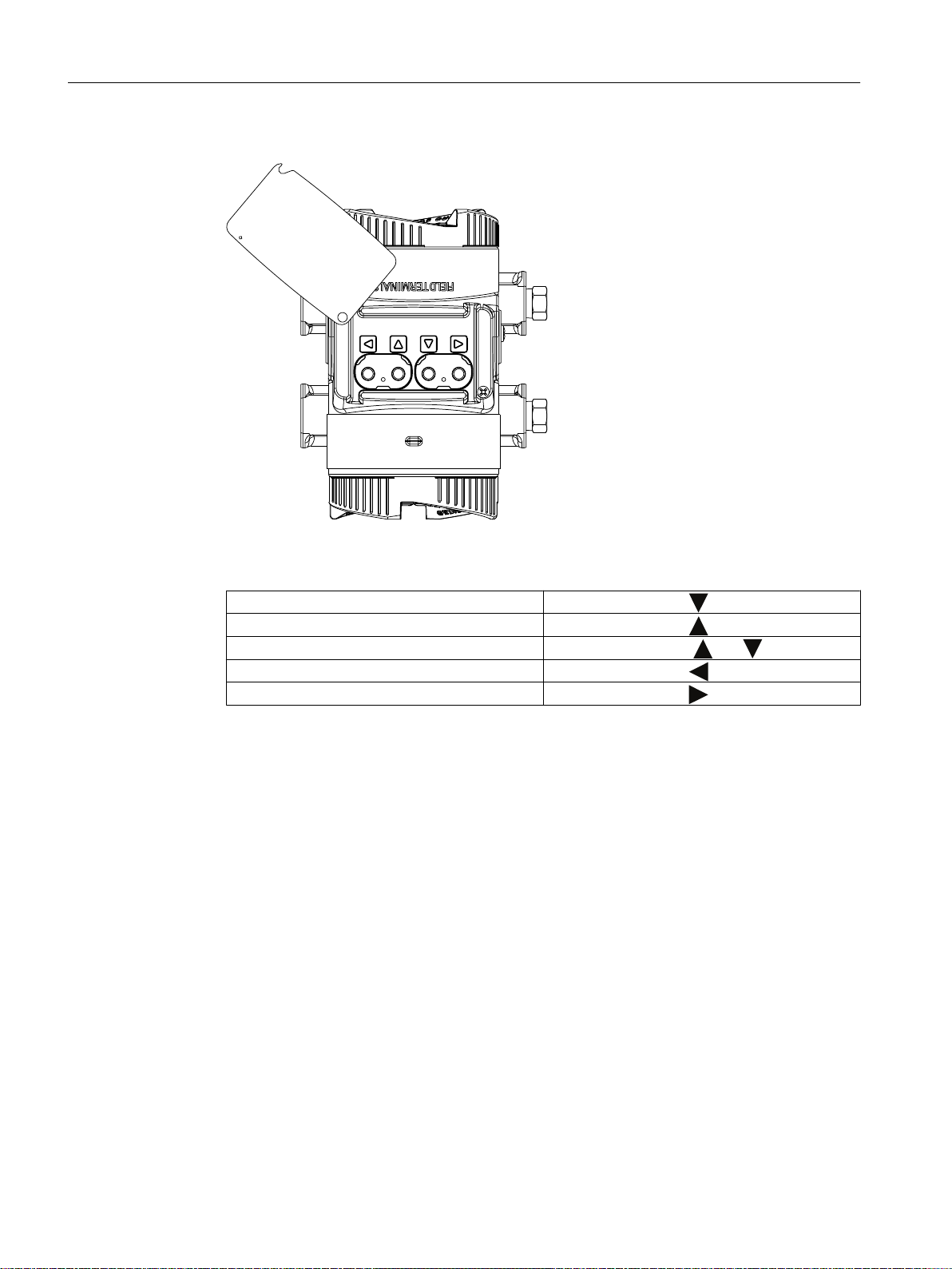
4. Open the cover of the buttons:
Figure 1-1 Top view
5. Operate the buttons as follows:
Apply lower range value (with pressure applied) Hold down the button for 3 seconds.
Apply upper range value (with pressure applied) Hold down the button for 3 seconds.
Zero point adjustment Hold down the buttons and for 3 seconds.
Set Upper fault current Hold down the button for 3 seconds.
Set Lower fault current Hold down the button for 3 seconds.
Further functions are available via remote operation (e.g. SIMATIC PDM).
1.2 Commissioning the device with display
Introduction
In this section, you will learn how to commission the device step-by-step.
Before you start, please read the following safety information:
● General safety information (Page 19)
● Basic safety information: Installing/mounting (Page 23)
● Basic safety information: Connecting (Page 37)
● Basic safety information: Commissioning (Page 45)
Read the entire device manual in order to achieve the optimum performance of the device.
SITRANS P320/P420 with 4 to 20 mA/HART
8 Compact Operating Instructions, 09/2018, A5E38874562-AB
Page 9

Procedure
Getting started
1.2 Commissioning the device with display
1. Mount the device.
Installation (except level) (Page 27)
Installation (level) (Page 30)
2. Connect the device.
Connecting the device (Page 41)
3. Switch on the power supply.
Switching on the supply voltage (Page 46)
4. Open the cover of the buttons:
5. Further functions can be found in the operating instructions.
– Set the measuring range.
– Set the pressure unit.
– Set the application of your device.
– Set the scaling points.
– Set the zero point.
– Lock the device.
– Enable Functional Safety (for devices with Functional Safety).
SITRANS P320/P420 with 4 to 20 mA/HART
Compact Operating Instructions, 09/2018, A5E38874562-AB 9
Page 10

Getting started
1.2 Commissioning the device with display
SITRANS P320/P420 with 4 to 20 mA/HART
10 Compact Operating Instructions, 09/2018, A5E38874562-AB
Page 11

Introduction
2.1 Purpose of this documentation
These instructions are a brief summary of important features, functions and safety information,
and contain all information required for safe use of the device. Read the instructions carefully
prior to installation and commissioning. In order to use the device correctly, first review its
principle of operation.
The instructions are aimed at persons who install and commission the device.
To realize optimum performance from the device, read the complete operating instructions.
2.2 Document history
The overview below summarizes the most important changes in the documentation when
compared to the previous edition.
Edition Note
09/2018
06/2018 First edition
● Section Getting started (Page 7) added.
● Basic safety instructions in the sections Use in hazardous areas (Page 21),
Installing/mounting (Page 23), Connecting (Page 37) updated.
● Section Connecting the device (Page 42) updated.
● Section Vibration resistance (Page 95) updated.
2
2.3 Scope of validity of this document
Variant SITRANS P320 mA/HART SITRANS P420 mA/HART
Gauge pressure 7MF0300 7MF0400
Gauge pressure from the differential
pressure series
Absolute pressure from the gauge pres‐
sure series
Absolute pressure from the differential
pressure series
Differential pressure and flow rate,
PN 160 (MAWP 2320 psi)
Differential pressure and flow rate, PN
420 (MAWP 6092 psi)
Level 7MF0360 7MF0460
SITRANS P320/P420 with 4 to 20 mA/HART
Compact Operating Instructions, 09/2018, A5E38874562-AB 11
7MF0310 7MF0410
7MF0320 7MF0420
7MF0330 7MF0430
7MF0340 7MF0440
7MF0350 7MF0450
Page 12

Introduction
2.5 Product compatibility
2.4 Intended use
Overview
Depending on the variant, the pressure transmitter measures corrosive, non-corrosive and
hazardous gases, vapors and liquids.
You can use the pressure transmitter for the following measuring tasks:
● Gauge pressure
● Absolute pressure
● Differential pressure
With the appropriate configuration and the necessary add-on parts (e.g. limiters and remote
seals), you can also use the pressure transmitter for the following measuring tasks:
● Level
● Volume flow
● Mass flow
● Volume
● Customized characteristic curve
The output signal for all measuring tasks is a direct current of 4 to 20 mA.
You can install the "intrinsically-safe" or "flameproof enclosure" version of the pressure
transmitter in hazardous areas. The devices have a test certification and comply with the
corresponding directives.
Pressure transmitters with remote seals of various shapes can be provided for special
applications. For example, measuring high-viscosity substances is a special application.
Operate the device in accordance with the specifications in section Technical data (Page 63).
2.5 Product compatibility
The following table describes the compatibility between the edition of this manual, the device
revision, the engineering system and the associated EDD.
Edition Comments Product compatibility Compatibility with device integra‐
09/2018 Manual re‐
vised
06/2018 First edition HART 7
HART 7
FW: 1.00.08 or higher
HW: 1.00.00 or higher
FW: 1.00.08 or higher
HW: 1.00.00 or higher
tion package
SIMATIC PDM V9.0 or higher
AMS Device Manager V13 or high‐
er
DTM Pactware V4.1 SP4
FC475 V3.9 or higher
SIMATIC PDM V9.0 or higher
AMS Device Manager V13 or high‐
er
DTM Pactware V4.1 SP4
FC475 V3.9 or higher
SITRANS P320/P420 with 4 to 20 mA/HART
12 Compact Operating Instructions, 09/2018, A5E38874562-AB
Page 13
2.6 Nameplate layout
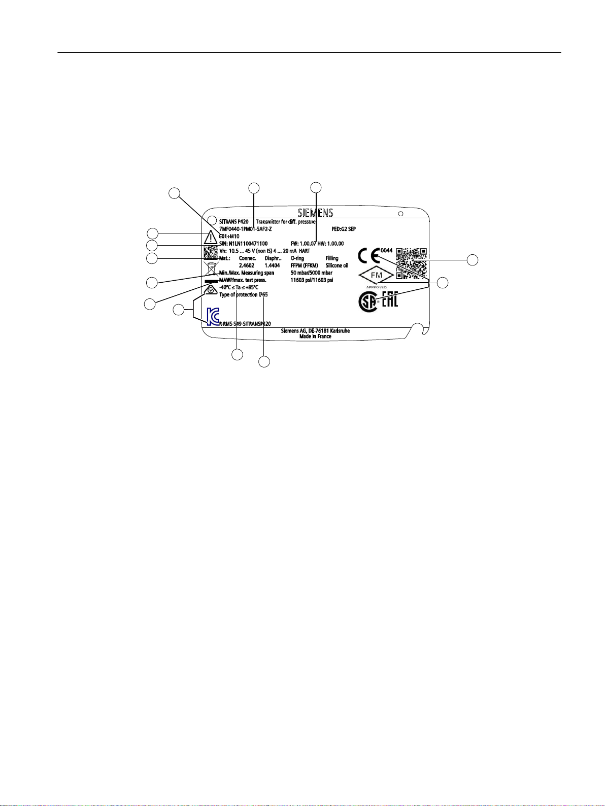
Nameplate with general information
The nameplate with the article number and other important information, such as design details
and technical data, is located on the cover over the buttons.
Introduction
2.6 Nameplate layout
① Firmware and hardware identification ⑦ Minimum/maximum measuring span
② Article number (MLFB number) ⑧ Maximum allowable operating pressure /
maximum allowable test pressure
③ Order supplement (order code) ⑨ Conformity with country-specific directives
④ Note operating instructions, certificates and ap‐
provals
⑩ Permitted ambient temperature for the
hazardous area of the corresponding tem‐
perature class
⑤ Serial number ⑪ Protection class
⑥ Materials, connection, diaphragm, O-ring, oil ⑫ QR code to the mobile website with device-
specific information
Figure 2-1 Example
SITRANS P320/P420 with 4 to 20 mA/HART
Compact Operating Instructions, 09/2018, A5E38874562-AB 13
Page 14
D
E
F
,,*([LD,,&777*D*E
H
G
.... to .... mbar
Long tag (TAG)
Measuring point description
Y01 (max. 5 characters)
Y16 (max. 32 characters)
max. 10 characters
Y99: 1234
<PD[FKDUDFWHUV
Introduction
2.6 Nameplate layout
Nameplate with approval information
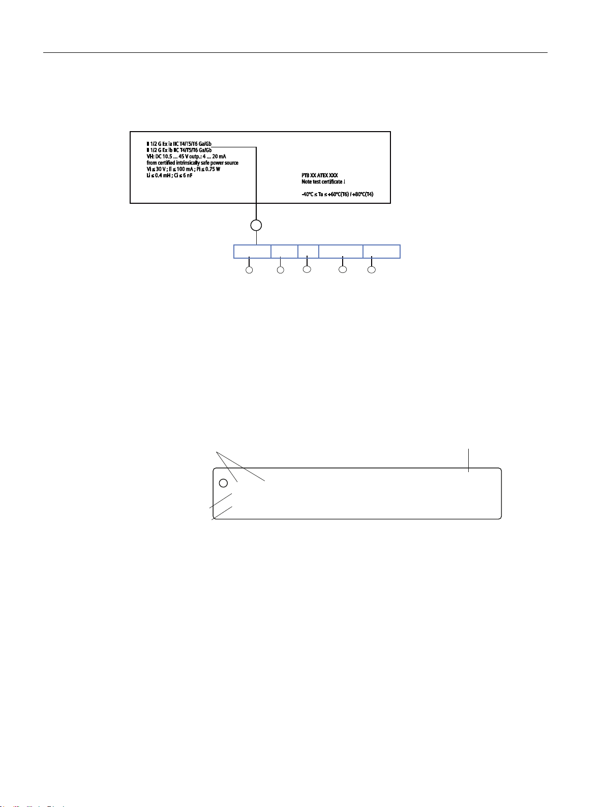
The nameplate with approval information is located on the front of the enclosure.
1a Characteristics of the hazardous area
1b Type of protection
1c Group (gas, dust)
1d Maximum surface temperature (temperature class)
1e Device protection level
Figure 2-2 Example
Measuring point label
The measuring point label is fastened with a wire under the front cover.
Figure 2-3 Example
14 Compact Operating Instructions, 09/2018, A5E38874562-AB
SITRANS P320/P420 with 4 to 20 mA/HART
Page 15
Nameplate with information on the remote seals
%&
,BSMTSVIF
%*"1)3"(.4&"-44"/%8*$)5:1&
1.'"""";
$$&
01&35&.1ާ
7"$$6.4&37*$&/0]09:(&/ࣙާࣙCBS
/0.*4*;&13&4ܝ&95&/4*0/ܞ$-"44
'*--*/(-*26*%'00%(3"%&0*-'%"(3"%&
8&55&%."5%*"1)'-"/%61-&9
4JFNFOT"(
4/+
"TTFNCMFEJO$BOBEB
$PNQPOFOUTPG'SBODF
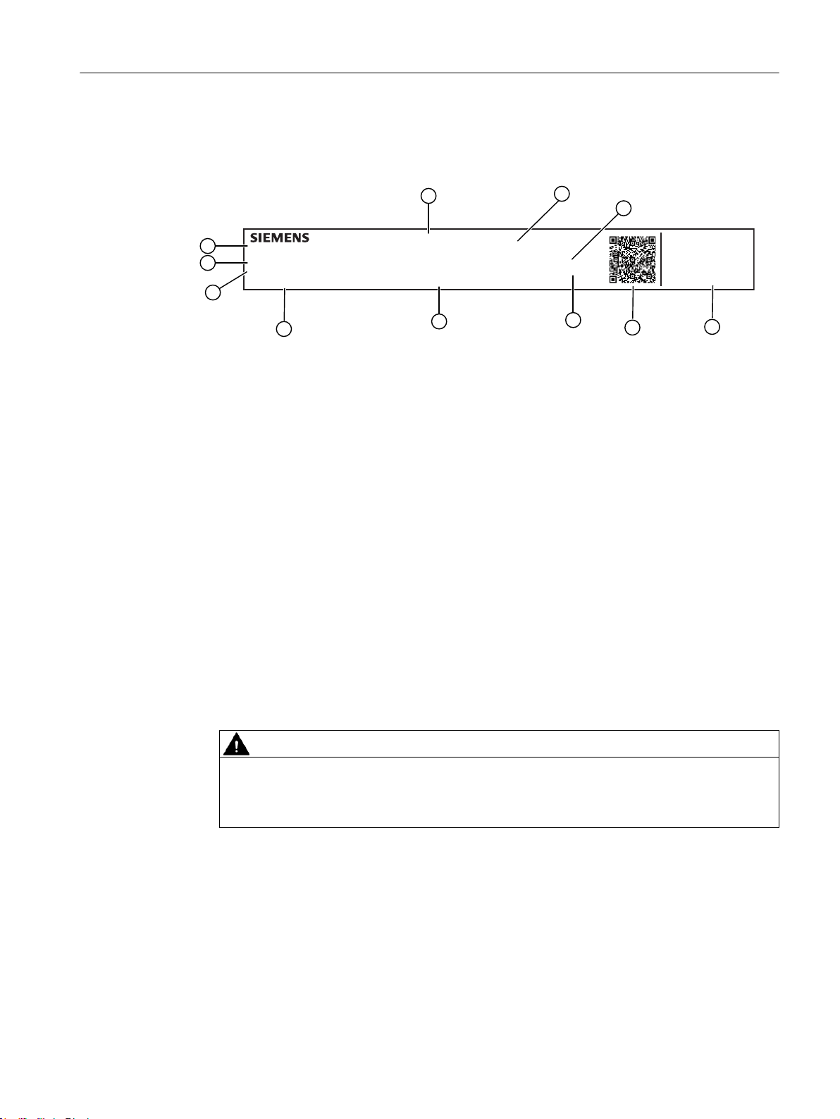
The nameplate with information on the remote seals is located on the back of the enclosure.
① Diaphragm remote seals of sandwich type ⑦ Nominal diameter/nominal pressure: 4 inch, 50
② Article number (MLFB number) ⑧ Filling liquid: Food grade oil (FDA-compliant)
③ Order supplement (order code) ⑨ Wetted materials: Diaphragm duplex, 1.4462
④ Serial number ⑩ QR code for mobile website with device-specific
⑤ Operating temperature ⑪ Assembly and manufacturing location
⑥ Vacuum service: No, oxygen ≤ 60 °C;
≤ 50 bar
Figure 2-4 Example
Introduction
2.8 Security information
mm tube length, CLASS 600
information
2.7 Checking the consignment
1. Check the packaging and the delivered items for visible damages.
2. Report any claims for damages immediately to the shipping company.
3. Retain damaged parts for clarification.
4. Check the scope of delivery by comparing your order to the shipping documents for
correctness and completeness.
WARNING
Using a damaged or incomplete device
Risk of explosion in hazardous areas.
● Do not use damaged or incomplete devices.
2.8 Security information
Siemens provides products and solutions with industrial security functions that support the
secure operation of plants, systems, machines, and networks.
In order to protect plants, systems, machines and networks against cyber threats, it is
necessary to implement – and continuously maintain – a holistic, state-of-the-art industrial
security concept. Siemens’ products and solutions only form one element of such a concept.
SITRANS P320/P420 with 4 to 20 mA/HART
Compact Operating Instructions, 09/2018, A5E38874562-AB 15
Page 16

Introduction
2.10 Notes on warranty
Customer is responsible to prevent unauthorized access to its plants, systems, machines and
networks. Systems, machines and components should only be connected to the enterprise
network or the internet if and to the extent necessary and with appropriate security measures
(e.g. use of firewalls and network segmentation) in place.
Additionally, Siemens’ guidance on appropriate security measures should be taken into
account. You can find more information about industrial security by visiting:
https://www.siemens.com/industrialsecurity.
Siemens’ products and solutions undergo continuous development to make them more secure.
Siemens strongly recommends you apply product updates as soon as available and always
use the latest product versions. Use of product versions that are no longer supported, and
failure to apply latest updates may increase customer’s exposure to cyber threats.
To stay informed about product updates, subscribe to the Siemens Industrial Security RSS
Feed under
https://www.siemens.com/industrialsecurity.
2.9 Transportation and storage
To guarantee sufficient protection during transport and storage, observe the following:
● Keep the original packaging for subsequent transportation.
● Devices/replacement parts should be returned in their original packaging.
● If the original packaging is no longer available, ensure that all shipments are properly
packaged to provide sufficient protection during transport. Siemens cannot assume liability
for any costs associated with transportation damages.
NOTICE
Insufficient protection during storage
The packaging only provides limited protection against moisture and infiltration.
● Provide additional packaging as necessary.
Special conditions for storage and transportation of the device are listed in Technical data
(Page 63).
2.10 Notes on warranty
The contents of this manual shall not become part of or modify any prior or existing agreement,
commitment or legal relationship. The sales contract contains all obligations on the part of
Siemens as well as the complete and solely applicable warranty conditions. Any statements
regarding device versions described in the manual do not create new warranties or modify the
existing warranty.
The content reflects the technical status at the time of publishing. Siemens reserves the right
to make technical changes in the course of further development.
SITRANS P320/P420 with 4 to 20 mA/HART
16 Compact Operating Instructions, 09/2018, A5E38874562-AB
Page 17
Safety instructions
3.1 Precondition for use
This device left the factory in good working condition. In order to maintain this status and to
ensure safe operation of the device, observe these instructions and all the specifications
relevant to safety.
Observe the information and symbols on the device. Do not remove any information or symbols
from the device. Always keep the information and symbols in a completely legible state.
3.1.1 Warning symbols on the device
Symbol Explanation
Consult operating instructions
3
3.1.2 Laws and directives
Observe the safety rules, provisions and laws applicable in your country during connection,
assembly and operation. These include, for example:
● National Electrical Code (NEC - NFPA 70) (USA)
● Canadian Electrical Code (CEC) (Canada)
Further provisions for hazardous area applications are for example:
● IEC 60079-14 (international)
● EN 60079-14 (EU)
SITRANS P320/P420 with 4 to 20 mA/HART
Compact Operating Instructions, 09/2018, A5E38874562-AB 17
Page 18

Safety instructions
3.2 Requirements for special applications
3.1.3 Conformity with European directives
The CE mark on the device is a sign of conformity with the following European directives:
Electromagnetic compatibility EMC
2014/30/EU
Atmosphère explosible ATEX
2014/34/EU
Pressure Equipment Directive
PED
2014/68/EU
The directives applied can be found in the EU declaration of conformity for the associated
device.
WARNING
Improper device modifications
Risk to personnel, system and environment can result from modifications to the device,
particularly in hazardous areas.
● Only carry out modifications that are described in the instructions for the device. Failure
to observe this requirement cancels the manufacturer's warranty and the product
approvals.
Directive of the European Parliament and of the Council on the harmonization
of the laws of the Member States relating to electromagnetic compatibility
Directive of the European Parliament and the Council on the harmonization of
the laws of the Member States concerning equipment and protective systems
intended for use in potentially explosive atmospheres
Directive of the European Parliament and of the Council on the harmonization
of the laws of the Member States relating to the making available on the market
of pressure equipment
3.2 Requirements for special applications
Due to the large number of possible applications, each detail of the described device versions
for each possible scenario during commissioning, operation, maintenance or operation in
systems cannot be considered in the instructions. If you need additional information not
covered by these instructions, contact your local Siemens office or company representative.
Note
Operation under special ambient conditions
We highly recommend that you contact your Siemens representative or our application
department before you operate the device under special ambient conditions as can be
encountered in nuclear power plants or when the device is used for research and development
purposes.
SITRANS P320/P420 with 4 to 20 mA/HART
18 Compact Operating Instructions, 09/2018, A5E38874562-AB
Page 19

DANGER
Using equipment with approval-related restrictions
Risk of explosion, damage to property due to operating conditions not in conformity with the
approval (e.g. temperature and pressure limits exceeded)
● Take note of the approval restrictions before using the device. You can find the information
on this in the current certificates.
3.3 Use in hazardous areas
Qualified personnel for hazardous area applications
Persons who install, connect, commission, operate, and service the device in a hazardous
area must have the following specific qualifications:
Safety instructions
3.3 Use in hazardous areas
See also
● They are authorized, trained or instructed in operating and maintaining devices and systems
according to the safety regulations for electrical circuits, high pressures, aggressive, and
hazardous media.
● They are authorized, trained, or instructed in carrying out work on electrical circuits for
hazardous systems.
● They are trained or instructed in maintenance and use of appropriate safety equipment
according to the pertinent safety regulations.
WARNING
Use in hazardous area
Risk of explosion.
● Only use equipment that is approved for use in the intended hazardous area and labelled
accordingly.
● Don't use devices that have been operated outside the conditions secified for hazardous
areas. If you have used the device outside the conditions for hazardous areas permanently
make all Ex markings unrecognizable on the nameplate.
Technical data (Page 63)
SITRANS P320/P420 with 4 to 20 mA/HART
Compact Operating Instructions, 09/2018, A5E38874562-AB 19
Page 20
Safety instructions
3.3 Use in hazardous areas
WARNING
Loss of safety of device with type of protection "Intrinsic safety Ex i"
If the device has already been operated in non-intrinsically safe circuits or the electrical
specifications have not been observed, the safety of the device is no longer ensured for use
in hazardous areas. There is a risk of explosion.
● Connect the device with type of protection "Intrinsic safety" solely to an intrinsically safe
circuit.
● Observe the specifications for the electrical data on the certificate and/or in Technical
data (Page 63).
WARNING
Use of incorrect device parts in potentially explosive environments
Devices and their associated device parts are either approved for different types of protection
or they do not have explosion protection. There is a risk of explosion if device parts (such as
covers) are used for devices with explosion protection that are not expressly suited for this
type of protection. If you do not adhere to these guidelines, the test certificates and the
manufacturer warranty will become null and void.
● Use only device parts that have been approved for the respective type of protection in the
potentially explosive environment. Covers that are not suited for the "explosion-proof" type
of protection are identified as such by a notice label attached to the inside of the cover
with "Not Ex d Not SIL".
● Do not swap device parts unless the manufacturer specifically ensures compatibility of
these parts.
WARNING
Use of the device with intrinsic safety "Ex i" type of protection in a polluted environment.
If you open the device on the display side, there is a risk of pollution. The safety of the device
for use in hazardous areas is therefore no longer guaranteed. There is a danger of explosion.
● Ensure that the environment is clean before rotating or replacing the display.
WARNING
Incorrect material for the diaphragm in Zone 0
Risk of explosion in the hazardous area. If operated with intrinsically safe supply devices of
category "ib" or devices of the flameproof enclosure version "Ex d" and simultaneous use in
Zone 0, pressure transmitter explosion protection depends on the tightness of the diaphragm.
● Ensure that the material used for the diaphragm is suitable for the process medium. Refer
to the information in the section "Technical data (Page 63)".
SITRANS P320/P420 with 4 to 20 mA/HART
20 Compact Operating Instructions, 09/2018, A5E38874562-AB
Page 21
Installing/mounting
4.1 Basic safety instructions
DANGER
Pressure applications
Danger to personnel, system and environment will result from improper disassembly.
● Never attempt to loosen, remove, or disassemble process connection while vessel
contents are under pressure.
WARNING
Wetted parts unsuitable for the process media
Risk of injury or damage to device.
Hot, toxic and corrosive media could be released if the process medium is unsuitable for the
wetted parts.
● Ensure that the material of the device parts wetted by the process medium is suitable for
the medium. Refer to the information in Technical data (Page 63).
4
WARNING
Unsuitable connecting parts
Risk of injury or poisoning.
In case of improper mounting, hot, toxic, and corrosive process media could be released at
the connections.
● Ensure that connecting parts (such as flange gaskets and bolts) are suitable for connection
and process media.
WARNING
Exceeded maximum permissible operating pressure
Risk of injury or poisoning.
The maximum permissible operating pressure depends on the device version, pressure limit
and temperature rating. The device can be damaged if the operating pressure is exceeded.
Hot, toxic and corrosive process media could be released.
Ensure that maximum permissible operating pressure of the device is not exceeded. Refer
to the information on the nameplate and/or in Technical data (Page 63).
SITRANS P320/P420 with 4 to 20 mA/HART
Compact Operating Instructions, 09/2018, A5E38874562-AB 21
Page 22
Installing/mounting
4.1 Basic safety instructions
WARNING
Incorrect material for the diaphragm in Zone 0
Risk of explosion in the hazardous area. If operated with intrinsically safe supply devices of
category "ib" or devices of the flameproof enclosure version "Ex d" and simultaneous use in
Zone 0, pressure transmitter explosion protection depends on the tightness of the diaphragm.
● Ensure that the material used for the diaphragm is suitable for the process medium. Refer
to the information in the section "Technical data (Page 63)".
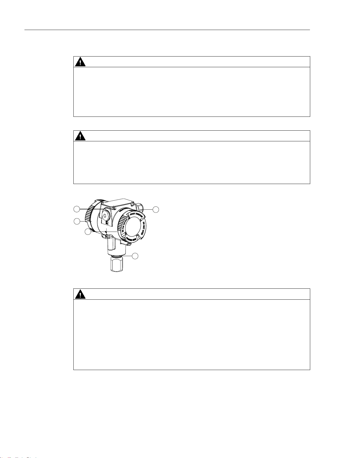
WARNING
Loss of safety for devices with "flameproof enclosure" type of protection
Risk of explosion in hazardous areas. An explosion may be caused by hot gas escaping from
the flameproof enclosure if there is too little space between it and fixed parts (e.g. walls, pipes).
● Ensure that there is a minimum clearance of at least 40 mm between the flameproof joints
and the fixed parts.
① Flameproof joint
WARNING
Vibrations in the plant
Risk of injury or damage to device.
Vibration leads to material fatigue, for example, cracks and weld seams breaks.
Hot, toxic and corrosive process media can emerge.
● Make sure that you have mounted the pressure transmitter (including accessories)
protected against vibration.
Refer to the information on vibration resistance in the section Technical specifications
(Page 63).
22 Compact Operating Instructions, 09/2018, A5E38874562-AB
SITRANS P320/P420 with 4 to 20 mA/HART
Page 23
Installing/mounting
4.1 Basic safety instructions
CAUTION
Hot surfaces resulting from hot process media
Risk of burns resulting from surface temperatures above 65 °C (149 °F).
● Take appropriate protective measures, for example contact protection.
● Make sure that protective measures do not cause the maximum permissible ambient
temperature to be exceeded. Refer to the information in Technical data (Page 63).
CAUTION
External stresses and loads
Damage to device by severe external stresses and loads (e.g. thermal expansion or pipe
tension). Process media can be released.
● Prevent severe external stresses and loads from acting on the device.
Note
Material compatibility
Siemens can provide you with support concerning selection of sensor components wetted by
process media. However, you are responsible for the selection of components. Siemens
accepts no liability for faults or failures resulting from incompatible materials.
WARNING
Use in wrong environment
Risk of explosion in hazardous areas.
● Use the device only in an area with at least a pollution degree 2 according to IEC 60664-1.
WARNING
Using safety extra-low voltage for devices of the protection type "db", "ec", "time" or "time"
Risk of explosion in hazardous areas.
● Isolate the non-intrinsically safe circuit safely from ground, e.g.: through a SELV circuit.
SITRANS P320/P420 with 4 to 20 mA/HART
Compact Operating Instructions, 09/2018, A5E38874562-AB 23
Page 24
Installing/mounting
4.1 Basic safety instructions
4.1.1 Installation location requirements
WARNING
Insufficient air supply
The device may overheat if there is an insufficient supply of air.
● Install the device so that there is sufficient air supply in the room.
● Observe the maximum permissible ambient temperature. Refer to the information in the
section Technical data (Page 63).
CAUTION
Aggressive atmospheres
Damage to device through penetration of aggressive vapors.
● Ensure that the device is suitable for the application.
NOTICE
Direct sunlight
Increased measuring errors.
● Protect the device from direct sunlight.
Make sure that the maximum ambient temperature is not exceeded. Refer to the information
in the section Technical data (Page 63).
4.1.1.1 Devices with marine approval
Note
For vibrations in the direction of the measuring cell diaphragm, the measuring accuracy of the
pressure transmitter with flush-mounted diaphragm can deviate no more than 0.2% from the
respective specification.
● Install the device so that no or almost no vibrations occur in the direction of the diaphragms.
● To avoid measuring values that fluctuate strongly, use the damping function.
For information on vibration resistance, refer to the marine approval certificate.
SITRANS P320/P420 with 4 to 20 mA/HART
24 Compact Operating Instructions, 09/2018, A5E38874562-AB
Page 25
4.1.2 Proper mounting
WARNING
Incorrect mounting at Zone 0
Risk of explosion in hazardous areas.
● Ensure sufficient tightness at the process connection.
● Observe the standard IEC/EN 60079-14.
CAUTION
Loss of type of protection
Damage to device if the enclosure is open or not properly closed. The type of protection
specified on the nameplate or in Technical data (Page 63) is no longer guaranteed.
● Make sure that the device is securely closed.
Installing/mounting
4.2 Installation (except level)
NOTICE
Incorrect mounting
The device can be damaged, destroyed, or its functionality impaired through improper
mounting.
● Before installing ensure there is no visible damage to the device.
● Make sure that process connectors are clean, and suitable gaskets and glands are used.
● Mount the device using suitable tools. Refer to the information in Technical data
(Page 63).
NOTICE
Use of line and cable entries made of plastic in hazardous areas
Device damage caused by impact at temperatures below -20 °C.
● Make sure that the line and cable entries are protected from impacts.
4.2 Installation (except level)
4.2.1 Installation configuration
The pressure transmitter can be configured above or below the pressure sampling point. The
recommended configuration depends on the aggregate state of the process medium.
SITRANS P320/P420 with 4 to 20 mA/HART
Compact Operating Instructions, 09/2018, A5E38874562-AB 25
Page 26

Installing/mounting
4.2 Installation (except level)
Installation configuration for gases
Install the pressure transmitter above the pressure sampling point.
Lay the pressure tubing with a constant gradient to the pressure sampling point, so that any
condensation produced can drain in the main line and thereby avoid corruption of the measured
values.
Installation configuration for vapor and liquid
Install the pressure transmitter below the pressure sampling point.
Lay the pressure tubing with a constant gradient to the pressure sampling point so that any
gas pockets can escape in the main line.
4.2.2 Installation (except level)
Mounting location
Verify that the mounting location meets the following conditions:
Requirement
● Accessible
● Close to the measuring point
● Vibration-free
● Within the permitted ambient temperature values
Protect the pressure transmitter from:
● Direct heat radiation
● Rapid temperature fluctuations
● Heavy contamination
● Mechanical damage
● Direct sunlight
● You have compared the desired operating data with the data on the nameplate.
● You have adhered to the information on the remote seal during its installation.
SITRANS P320/P420 with 4 to 20 mA/HART
26 Compact Operating Instructions, 09/2018, A5E38874562-AB
Page 27

Procedure
1. Attach the pressure transmitter to the process connection.
Use an appropriate tool (e.g. open-ended wrench with width across flats 36). Otherwise,
the measuring cell may be damaged.
2. Turn only on the key area above the process connection.
Caution: If you turn the pressure transmitter on the housing, the measuring cell may be
damaged.
3. To guarantee secure and vibration-free installation of the pressure transmitter, fasten it to
a mounting bracket (Page 29).
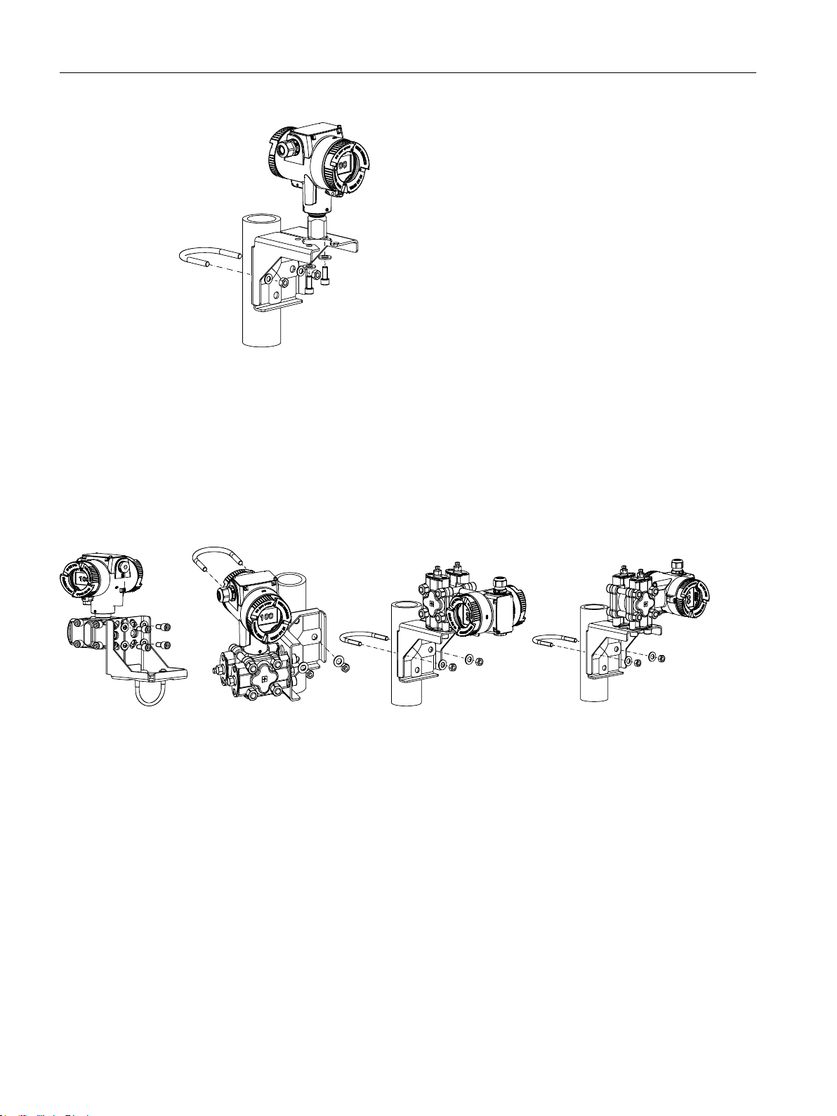
4.2.3 Fastening with the mounting bracket
Introduction
You mount the pressure transmitter with the mounting bracket as described below:
● On a mounting range
Installing/mounting
4.2 Installation (except level)
● On a vertical or horizontal pipe (Ø 50 to 60 mm)
When securing, observe the torques in the section Torques (Page 101).
Note
Install the device so that the pressure transmitter and the differential pressure lines are not
subject to different vibrations. Otherwise there is a danger that the differential pressure lines
will rupture.
Example 1: Pipe mounting of pressure transmitter (gauge pressure series)
The mounting bracket for the gauge pressure series includes, among other things:
● 2 screws
● One pipe clamp with nuts
● Washers
Mount the pressure transmitter as follows:
SITRANS P320/P420 with 4 to 20 mA/HART
Compact Operating Instructions, 09/2018, A5E38874562-AB 27
Page 28
Installing/mounting
4.3 Installation (level)
Example 2: Pipe mounting of pressure transmitter (differential pressure series)
The mounting bracket for the differential pressure series includes, among other things:
● 4 screws
● One pipe clamp with nuts
● Washers
You can then mount the pressure transmitter in different positions:
4.3 Installation (level)
Mounting location
Verify that the mounting location meets the following conditions:
● Accessible
● Close to the measuring point
● Vibration-free
● Within the permitted ambient temperature values
SITRANS P320/P420 with 4 to 20 mA/HART
28 Compact Operating Instructions, 09/2018, A5E38874562-AB
Page 29

Requirement
Installing/mounting
4.3 Installation (level)
Protect the pressure transmitter from:
● Direct heat radiation
● Rapid temperature fluctuations
● Heavy contamination
● Mechanical damage
● Direct sunlight
Note
Select the height of the mounting flange such that the pressure transmitter is always mounted
below the lowest fill height to be measured.
● You have compared the desired operating data with the data on the nameplate.
● You have adhered to the information on the remote seal during its installation.
Procedure
To install the pressure transmitter for level, proceed as follows:
1. Attach the seal to the container's mating flange.
Ensure that the seal is centrally positioned and that it does not restrict the movement of the
flange's seal diaphragm in any way. Otherwise, the seal of the process connection is not
guaranteed to be tight.
2. Screw on the pressure transmitter's flange.
3. Observe the installation position.
4.3.1 Mounting on the container
Mounting on open container
A line is not required when taking measurements in an open container since the negative side
is connected with the atmosphere.
Ensure that no dirt enters the open connection ports.
● Use, for example, threaded plug with vent valve 7MF4997-1CP.
SITRANS P320/P420 with 4 to 20 mA/HART
Compact Operating Instructions, 09/2018, A5E38874562-AB 29
Page 30
+
)XOOVFDOHYDOXH
6WDUWRIVFDOHYDOXH
K
2
K
8
Installing/mounting
4.3 Installation (level)
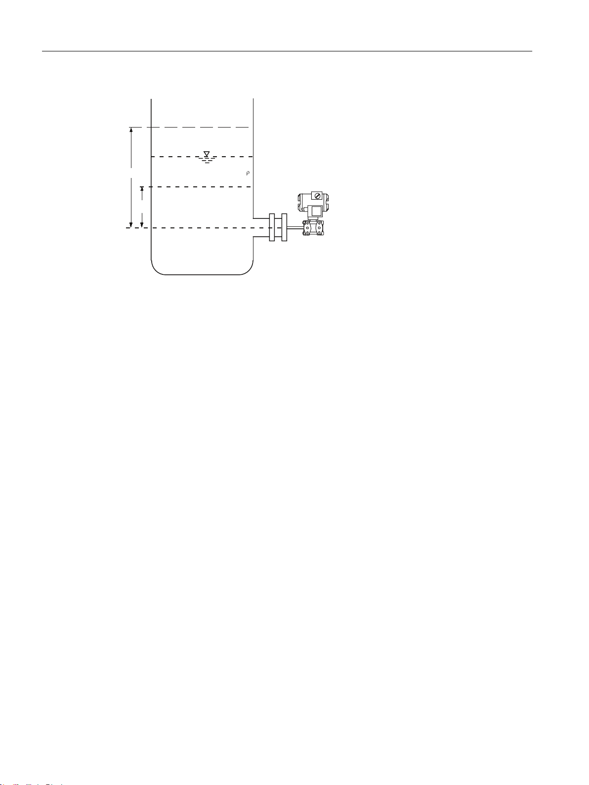
Measurement assembly on an open container
Formula:
Lower range value: p
Upper range value: p
= ρ · g · h
MA
= ρ · g · h
ME
U
O
h
h
Lower filling level Δp
U
Upper filling level Δp
O
p Pressure ρ Density of the measured medium in the
g Acceleration due to gravity
Mounting on closed container
When taking measurements in a closed container without or with little condensate formation,
the negative pressure line is not filled.
Lower range value
MA
Upper range value
ME
container
30 Compact Operating Instructions, 09/2018, A5E38874562-AB
SITRANS P320/P420 with 4 to 20 mA/HART
Page 31
)XOOVFDOHYDOXH
6WDUWRIVFDOHYDOXH
0D[LPXPOHYHO
K
2
K
8
*DVILOOHGQHJDWLYH
SUHVVXUHOLQH
3UHVVXUHWUDQVPLWWHU
UHIHUHQFHOLQH
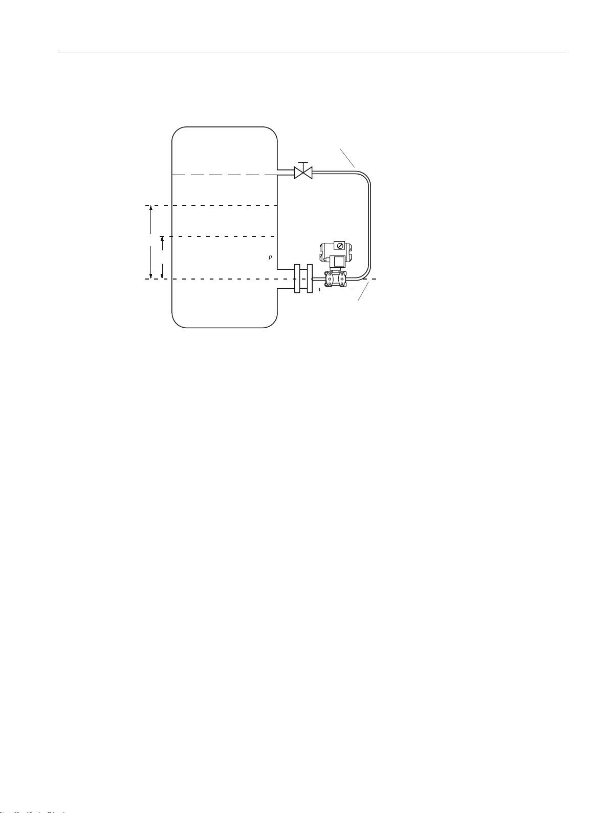
Installing/mounting
4.3 Installation (level)
Lay the line in such a way that condensation pockets do not form. If required, you need to
install a condensation container below the negative pressure line of the pressure transmitter.
Formula:
Lower range value: ΔpMA = ρ · g · h
Upper range value: ΔpME = ρ · g · h
U
O
Measurement assembly on a closed container (no or little
condensate separation)
h
h
Lower filling level Δp
U
Upper filling level Δp
O
Lower range value
MA
Upper range value
ME
p Pressure ρ Density of the measured medium in the
container
g Acceleration due to gravity
When taking measurements in a closed container with strong condensate formation, you must
fill the negative pressure line (mostly with the condensate of the measured medium) and install
a condensate pot. Lock the device using the dual pneumatic block 7MF9017-..A.
SITRANS P320/P420 with 4 to 20 mA/HART
Compact Operating Instructions, 09/2018, A5E38874562-AB 31
Page 32
'
-
K
2
K
8
)XOOVFDOHYDOXH
6WDUWRIVFDOHYDOXH
0D[LPXPOHYHO
&RQVWDQW
&RPSDULVRQ
OHYHO
*DVILOOHG
QHJDWLYHSUHVVXUHOLQH
K
Y
3UHVVXUHWUDQVPLWWHU
UHIHUHQFHOLQH
Installing/mounting
4.3 Installation (level)
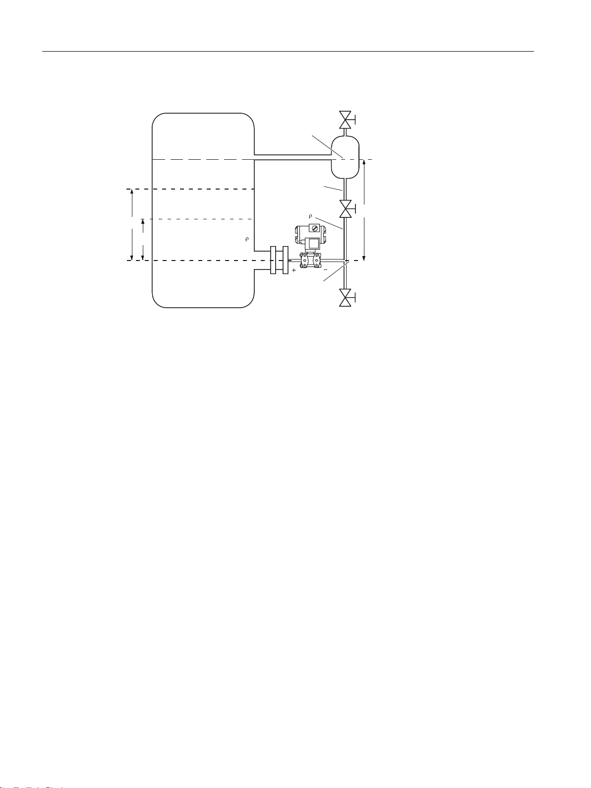
To compensate the liquid column on the minus side, reset the zero point.
Measurement assembly on a closed container (strong condensate
formation)
Formula:
Lower range value:
ΔpMA = g · (hU · ρ - hV · ρ')
Upper range value:
ΔpMA = g · (hO · ρ - hV · ρ')
h
h
h
Lower filling level Δp
U
Upper filling level Δp
O
Gland distance ρ Density of the measured medium in the
V
Lower range value
MA
Upper range value
ME
container
p Pressure ρ ' Density of fluid in the negative pressure
line corresponds to the prevailing tem‐
perature there
g Acceleration due to gravity
The process connection on the negative side is a female thread 1/4-18 NPT or an oval flange.
Lay the line for the negative pressure using a seamless steel tube 12 mm x 1.5 mm.
32 Compact Operating Instructions, 09/2018, A5E38874562-AB
SITRANS P320/P420 with 4 to 20 mA/HART
Page 33

4.4 Removing
WARNING
Incorrect disassembly
The following risks may result from incorrect disassembly:
- Injury through electric shock
- Risk through emerging media when connected to the process
- Risk of explosion in hazardous area
In order to disassemble correctly, observe the following:
● Before starting work, make sure that you have switched off all physical variables such as
pressure, temperature, electricity etc. or that they have a harmless value.
● If the device contains hazardous media, it must be emptied prior to disassembly. Make
sure that no environmentally hazardous media are released.
● Secure the remaining connections so that no damage can result if the process is started
unintentionally.
Installing/mounting
4.4 Removing
SITRANS P320/P420 with 4 to 20 mA/HART
Compact Operating Instructions, 09/2018, A5E38874562-AB 33
Page 34

Installing/mounting
4.4 Removing
SITRANS P320/P420 with 4 to 20 mA/HART
34 Compact Operating Instructions, 09/2018, A5E38874562-AB
Page 35

Connecting
5.1 Basic safety instructions
WARNING
Unsuitable cables, cable glands and/or plugs
Risk of explosion in hazardous areas.
● Use only cable glands/plugs that comply with the requirements for the relevant type of
protection.
● Tighten the cable glands in accordance with the torques specified in Technical data
(Page 63).
● Close unused cable inlets for the electrical connections.
● When replacing cable, glands use only cable glands of the same type.
● After installation, check that the cables are seated firmly.
WARNING
Incorrect conduit system
5
Risk of explosion in hazardous areas as result of open cable inlet or incorrect conduit system.
● In the case of a conduit system, mount a spark barrier at a defined distance from the device
input. Observe national regulations and the requirements stated in the relevant approvals.
WARNING
Unprotected cable ends
Risk of explosion through unprotected cable ends in hazardous areas.
● Protect unused cable ends in accordance with IEC/EN 60079-14.
SITRANS P320/P420 with 4 to 20 mA/HART
Compact Operating Instructions, 09/2018, A5E38874562-AB 35
Page 36
Connecting
5.1 Basic safety instructions
WARNING
Lack of equipotential bonding
Danger of explosion through compensating currents or ignition currents through lack of
equipotential bonding.
For devices of intrinsic safety "db", "ec", "tb" or "tc" which are operated in a non-intrinsically
safe circuit, observe the following:
● Connect the device to the system via the equipotential bonding terminal.
Note: For devices of the intrinsic safety "ia", "ib" and "ic" type of protection, which are operated
in an intrinsically safe circuit, connection to the system via the equipotential bonding terminal
is not required.
WARNING
Improper laying of shielded cables
Risk of explosion through compensating currents between hazardous area and the
non‑hazardous area.
● Shielded cables that cross into hazardous areas should be grounded only at one end.
● If grounding is required at both ends, use an equipotential bonding conductor.
WARNING
Connecting device in energized state
Risk of explosion in hazardous areas.
● Connect devices in hazardous areas only in a de-energized state.
Exceptions:
● Devices having the type of protection "Intrinsic safety Ex i" may also be connected in
energized state in hazardous areas.
● Exceptions for type of protection "Increased safety ec" (Zone 2) are regulated in the
relevant certificate.
SITRANS P320/P420 with 4 to 20 mA/HART
36 Compact Operating Instructions, 09/2018, A5E38874562-AB
Page 37
,,*([LD,,&77*D*E
,,*([LDGE,,&77*D*E
Connecting
5.1 Basic safety instructions
WARNING
Incorrect selection of type of protection
Risk of explosion in hazardous areas.
This device is approved for various types of protection.
1. Select an intrinsic safety type of protection "ia", "ib", "ic" or non-intrinsic safety "db", "tb",
"tc", "ec".
2. Connect the device according to the selected type of protection.
3. When operating with non-intrinsically safe power supplies, make the intrinsically safe types
of protection permanently unrecognizable as in the example.
Figure 5-1 Example: Type 7MF0..0-.....-.D..-Z + E20
NOTICE
Ambient temperature too high
Damage to cable sheath.
● At an ambient temperature ≥ 60 °C (140 °F), use heat-resistant cables suitable for an
ambient temperature at least 20 °C (36 °F) higher.
NOTICE
Condensation in the device
Damage to device through formation of condensation if the temperature difference between
transportation or storage and the mounting location exceeds 20 °C (36 °F).
● Before taking the device into operation let the device adapt for several hours in the new
environment.
NOTICE
Incorrect measured values with incorrect grounding
The device must not be grounded using the "+" connection. It may otherwise malfunction and
be permanently damaged.
● If necessary, ground the device using the "-" connection.
SITRANS P320/P420 with 4 to 20 mA/HART
Compact Operating Instructions, 09/2018, A5E38874562-AB 37
Page 38

Connecting
5.1 Basic safety instructions
Note
Electromagnetic compatibility (EMC)
You can use this device in industrial environments, households and small businesses.
For metal housings there is an increased electromagnetic compatibility compared to highfrequency radiation. This protection can be increased by grounding the housing, see Technical
data (Page 63).
Note
Improvement of interference immunity
● Lay signal cables separate from cables with voltages > 60 V.
● Use cables with twisted wires.
● Keep device and cables at a distance from strong electromagnetic fields.
● Take account of the conditions for communication specified in the Technical data
(Page 63).
● Use shielded cables to guarantee the full specification according to HART/PA/FF.
SITRANS P320/P420 with 4 to 20 mA/HART
38 Compact Operating Instructions, 09/2018, A5E38874562-AB
Page 39
5.2 Connecting the device
5.2.1 Opening the device
Procedure
Connecting
5.2 Connecting the device
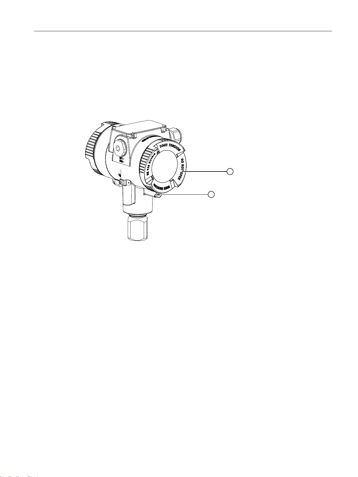
① Safety catch (optional)
② Cover of the electrical cable compartment.
Figure 5-2 Rear view of pressure transmitter
1. Use a 3 mm Allen key to loosen the safety catch ①.
2. Unscrew the cover of the electrical cable compartment ②.
SITRANS P320/P420 with 4 to 20 mA/HART
Compact Operating Instructions, 09/2018, A5E38874562-AB 39
Page 40
˖
- Test +
Connecting
5.2 Connecting the device
5.2.2 Connecting the device
Procedure
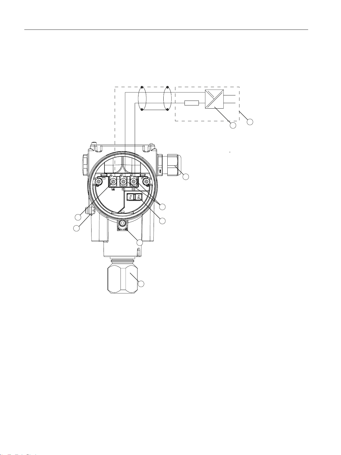
① Feed separator with integrated load ⑥ Safety catch
② Supply voltage ⑦ Process connection
③ Cable gland ⑧ Protective conductor connector/
equipotential bonding terminal
④ Connecting terminals ⑨ Ground terminal
⑤ Test connector for DC measuring device
Figure 5-3 Example: Electrical connection with feed separator
1. Connect the device to the system via the existing protective ground connection ⑧ by
observing the torques.
– Use a cable with a diameter of 1 … 4 mm2.
2. Insert the connecting cable through the cable gland ③.
SITRANS P320/P420 with 4 to 20 mA/HART
40 Compact Operating Instructions, 09/2018, A5E38874562-AB
Page 41
See also
Connecting
5.2 Connecting the device
3. Connect the wires to the connection terminals ④ "+" and "-", observing the polarity and the
torques.
– Use wires with a diameter of 0.5 ... 2.5 mm2.
– If you use stranded wire used, you need a ferrule.
4. Apply the shield to the screw of the ground terminal ⑨.
The screw of the ground terminal is electrically connected to the external protective
conductor connection.
NOTICE
Incorrect measured values with incorrect grounding
The device must not be grounded using the "+" connection. It may otherwise malfunction
and be permanently damaged.
● If necessary, ground the device using the "-" connection.
Torques (Page 101)
5.2.3 Closing the device
Procedure
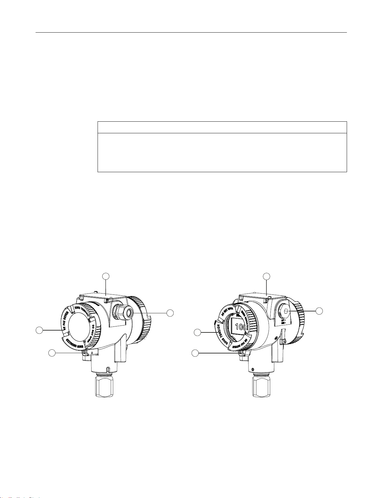
① Cover over buttons ⑤ Blanking plug
② Cable gland ⑥ Safety catch (front)
③ Safety catch (back) ⑦ Cover (front), optionally with inspection window
④ Cover (rear) for electrical terminal compartment
Figure 5-4 View of the pressure transmitter: Left: Back right: Front view
SITRANS P320/P420 with 4 to 20 mA/HART
Compact Operating Instructions, 09/2018, A5E38874562-AB 41
Page 42

Connecting
5.2 Connecting the device
1. Screw on the cover ④ and ⑦ as far as it will go.
Make sure that there is no gap between enclosure and cover.
2. Secure each cover with the cover catch ③ and ⑥ by removing the screw.
3. Close the cover over the buttons①.
4. Tighten the screw for the cover over the buttons.
5. Check the tightness of the blanking plug ⑤ and cable gland ② in accordance with the
degree of protection.
SITRANS P320/P420 with 4 to 20 mA/HART
42 Compact Operating Instructions, 09/2018, A5E38874562-AB
Page 43
Commissioning
6.1 Basic safety instructions
DANGER
Toxic gases and liquids
Danger of poisoning when venting the device: if toxic process media are measured, toxic
gases and liquids can be released.
● Before venting ensure that there are no toxic gases or liquids in the device, or take the
appropriate safety measures.
WARNING
Improper commissioning in hazardous areas
Device failure or risk of explosion in hazardous areas.
● Do not commission the device until it has been mounted completely and connected in
accordance with the information in Technical data (Page 63).
● Before commissioning take the effect on other devices in the system into account.
6
WARNING
Commissioning and operation with pending error
If an error message appears, correct operation in the process is no longer guaranteed.
● Check the gravity of the error.
● Correct the error.
● If the error still exists:
– Take the device out of operation.
– Prevent renewed commissioning.
WARNING
Loss of explosion protection
Risk of explosion in hazardous areas if the device is open or not properly closed.
● Close the device as described in Connecting (Page 35).
SITRANS P320/P420 with 4 to 20 mA/HART
Compact Operating Instructions, 09/2018, A5E38874562-AB 43
Page 44
Commissioning
6.2 Switching on the supply voltage
WARNING
Opening device in energized state
Risk of explosion in hazardous areas
● Only open the device in a de-energized state.
● Check prior to commissioning that the cover, cover locks, and cable inlets are assembled
in accordance with the directives.
Exception: Devices having the type of protection "Intrinsic safety Ex i" may also be opened
in energized state in hazardous areas.
WARNING
Hazardous contact voltage
Risk of injury through hazardous contact voltage when the device is open or not completely
closed.
The degree of protection specified on the nameplate or in Technical data (Page 63) is no
longer guaranteed if the device is open or not properly closed.
● Make sure that the device is securely closed.
Note
Hot surfaces
Hot process medium and high ambient temperatures lead to hot surfaces which can cause
burns.
● Take corresponding protective measures, for example wear protective gloves.
6.2 Switching on the supply voltage
Requirement
● You have connected the device correctly.
● The terminal voltage on the device is correct. (Page 101)
SITRANS P320/P420 with 4 to 20 mA/HART
44 Compact Operating Instructions, 09/2018, A5E38874562-AB
Page 45

Commissioning
6.4 gauge pressure, absolute pressure from the differential pressure series and absolute pressure from the gauge pressure series
Procedure
Switch on the power supply.
● Product name and firmware version appear briefly on the display.
● The measured values are shown on the display.
For a device without a display, you read off the current output as follows:
– Over the remote control (e.g. SIMATIC PDM).
– With a DC current measuring device.
Connecting the device (Page 40)
Result
The device is now ready for operation.
6.3 Commissioning the device
Ensure that the operating data matches the values specified on the nameplate.
The parameters for damping, characteristic curve, start of scale value/full scale value and fault
current must agree with the settings of the measuring point.
You can find more detailed information on operation and configuration in the operating
instructions.
The following commissioning cases are typical examples. Configurations different from those
listed here may be useful depending on the system configuration.
6.4 gauge pressure, absolute pressure from the differential pressure
series and absolute pressure from the gauge pressure series
6.4.1 Commissioning for gases
Requirement
All valves are closed.
SITRANS P320/P420 with 4 to 20 mA/HART
Compact Operating Instructions, 09/2018, A5E38874562-AB 45
Page 46
Commissioning
6.4 gauge pressure, absolute pressure from the differential pressure series and absolute pressure from the gauge
pressure series
Procedure
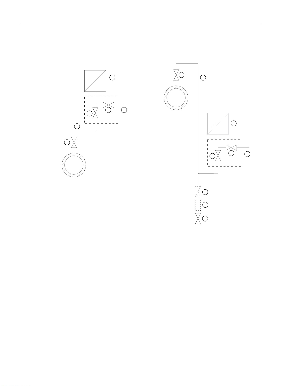
Example: Measuring gases above the
pressure tapping point
Example: Measuring gases below the
pressure tapping point
① Pressure transmitter ⑤ Pressure line
② Shut-off valve ⑥ Shut-off valve
③ Shut-off valve to process ⑦ Shut-off valve (optional)
④ Shut-off valve for test connection
To commission the pressure transmitter for gases, proceed as follows:
1. Open the shut-off valve for the test connection ④.
2. Via the test connection of the shut-off valve ②, apply the pressure corresponding to the
3. Ensure that the lower range value corresponds to the desired value. Otherwise, correct the
4. Close the shut-off valve for the test connection ④.
46 Compact Operating Instructions, 09/2018, A5E38874562-AB
or for bleed screw
start of scale value to the pressure transmitter.
value.
⑧ Condensate vessel (optional)
⑨ Blowout valve
SITRANS P320/P420 with 4 to 20 mA/HART
Page 47
Commissioning
6.4 gauge pressure, absolute pressure from the differential pressure series and absolute pressure from the gauge
pressure series
5. Open the shut-off valve ⑥ at the pressure tapping point.
6. Open the shut-off valve for the process ③.
6.4.2 Commissioning with steam or liquid
Requirement
All valves are closed.
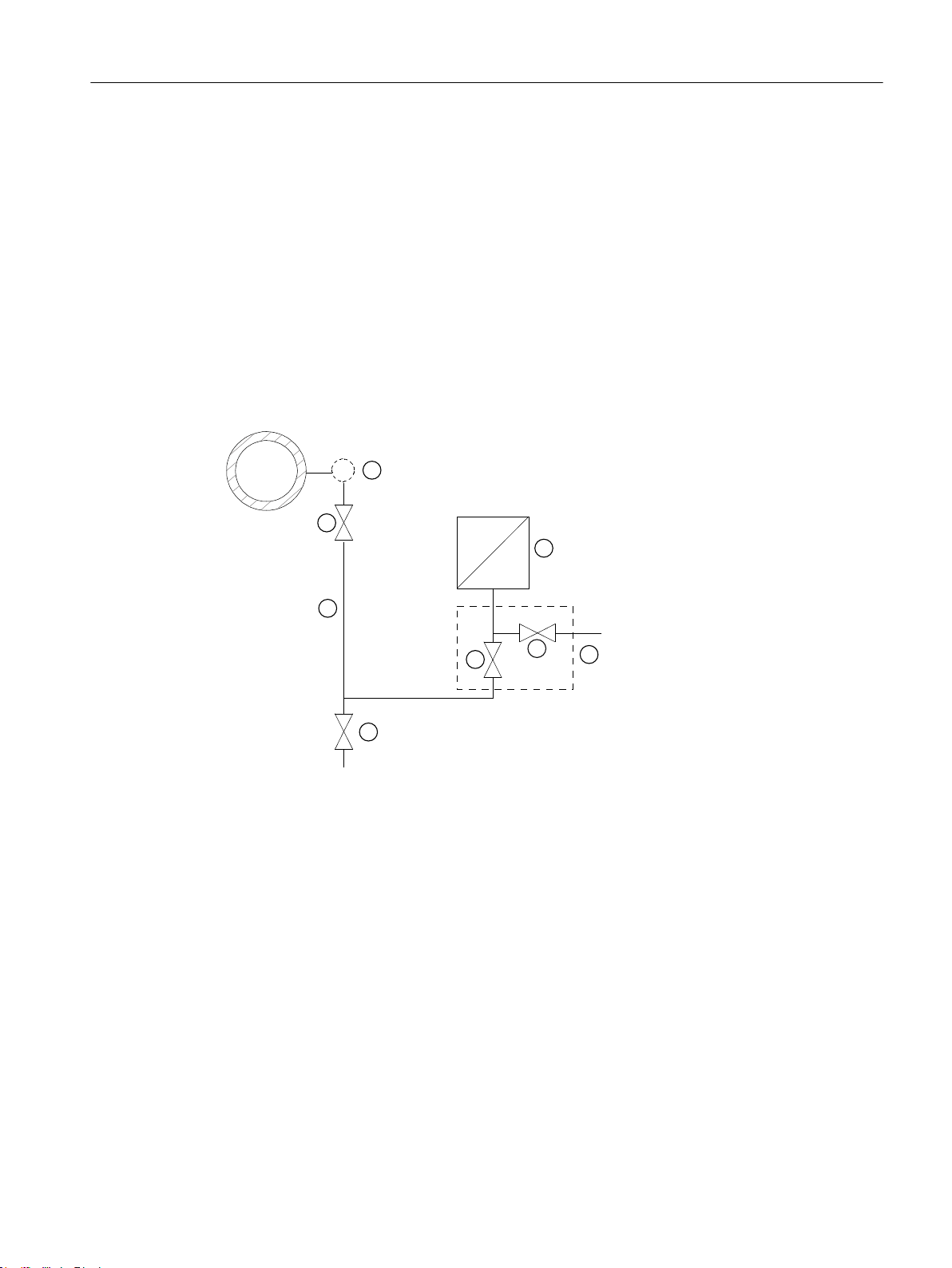
Procedure
① Pressure transmitter
② Shut-off valve
③ Shut-off valve to process
④ Shut-off valve for test connection or for bleed screw
⑤ Pressure line
⑥ Shut-off valve
⑦ Drain valve
⑧ Compensation vessel (steam only)
SITRANS P320/P420 with 4 to 20 mA/HART
Compact Operating Instructions, 09/2018, A5E38874562-AB 47
To commission the pressure transmitter for steam or liquid, proceed as follows:
1. Open the shut-off valve for the test connection ④.
2. Via the test connection of the shut-off valve ②, apply the pressure corresponding to the
start of scale value to the pressure transmitter.
3. Ensure that the lower range value corresponds to the desired value. Otherwise, correct the
value.
4. Close the shut-off valve for the test connection ④.
Page 48

Commissioning
6.5 Differential pressure and flow rate
5. Open the shut-off valve ⑥ at the pressure tapping point.
6. Open the shut-off valve for the process ③.
6.5 Differential pressure and flow rate
WARNING
Incorrect or improper operation
If the lock screws are missing or are not sufficiently tight, and/or if the valves are operated
incorrectly or improperly, it could lead to serious physical injuries or considerable damage to
property.
Measure
● Make sure that the lock screws and/or the vent valve are screwed in and fully tightened.
● Operate the valves properly.
6.5.1 Commissioning in gaseous environments
Requirement
All shut-off valves are closed.
SITRANS P320/P420 with 4 to 20 mA/HART
48 Compact Operating Instructions, 09/2018, A5E38874562-AB
Page 49
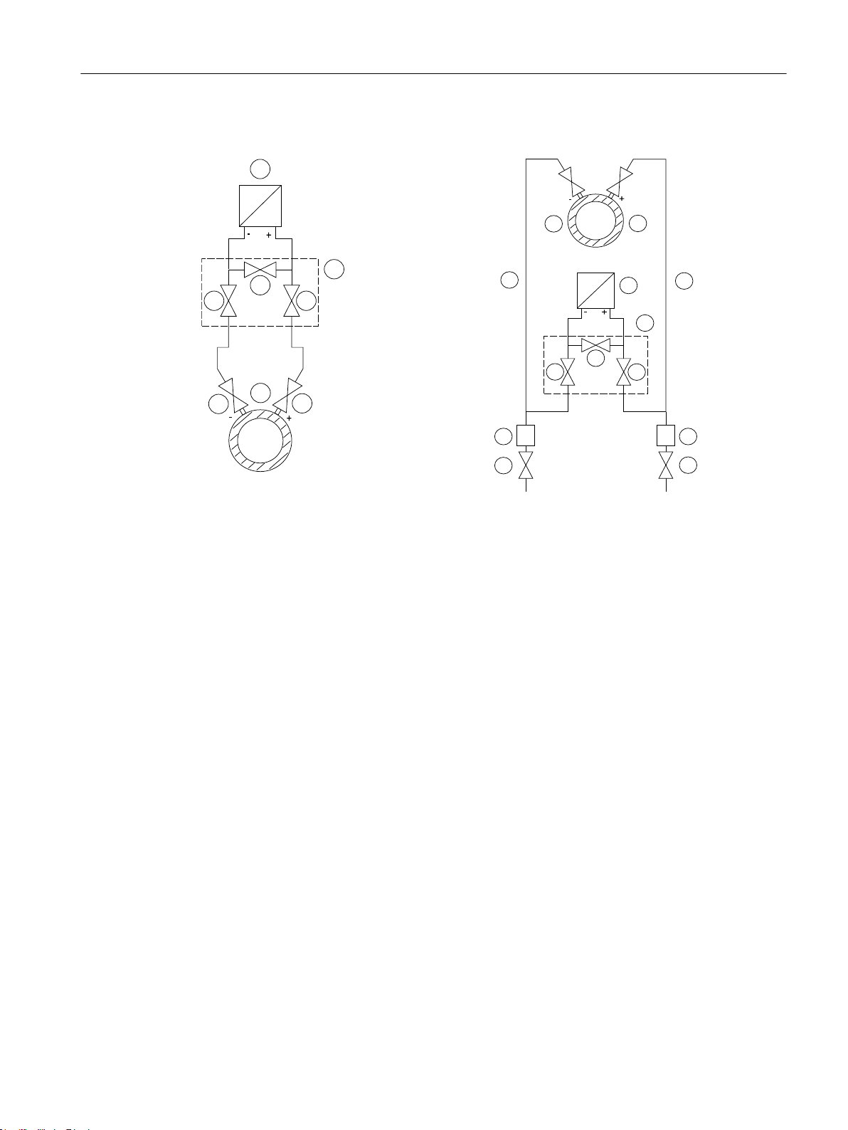
Procedure
Commissioning
6.5 Differential pressure and flow rate
Pressure transmitter above the differential pressure
transducer
Pressure transmitter below the differential pressure
transducer
① Pressure transmitter ⑦ Blowout valves
② Stabilizing valve ⑧ Condensate vessels (optional)
③, ④ Differential pressure valves ⑨ Differential pressure transducer
⑤ Differential pressure lines ⑩ 3-way valve manifold
⑥ Shut-off valves
To commission the pressure transmitter for gases, proceed as follows:
1. Open both the shut-off valves ⑥ at the pressure tapping point.
2. Open the stabilizing valve ②.
3. Open the differential pressure valve (③ or ④).
4. Check and, if necessary, correct the zero point when the start-of-scale value is 0 bar (4 mA).
5. Close the stabilizing valve ②.
6. Open the other differential pressure valve (③ or ④).
SITRANS P320/P420 with 4 to 20 mA/HART
Compact Operating Instructions, 09/2018, A5E38874562-AB 49
Page 50
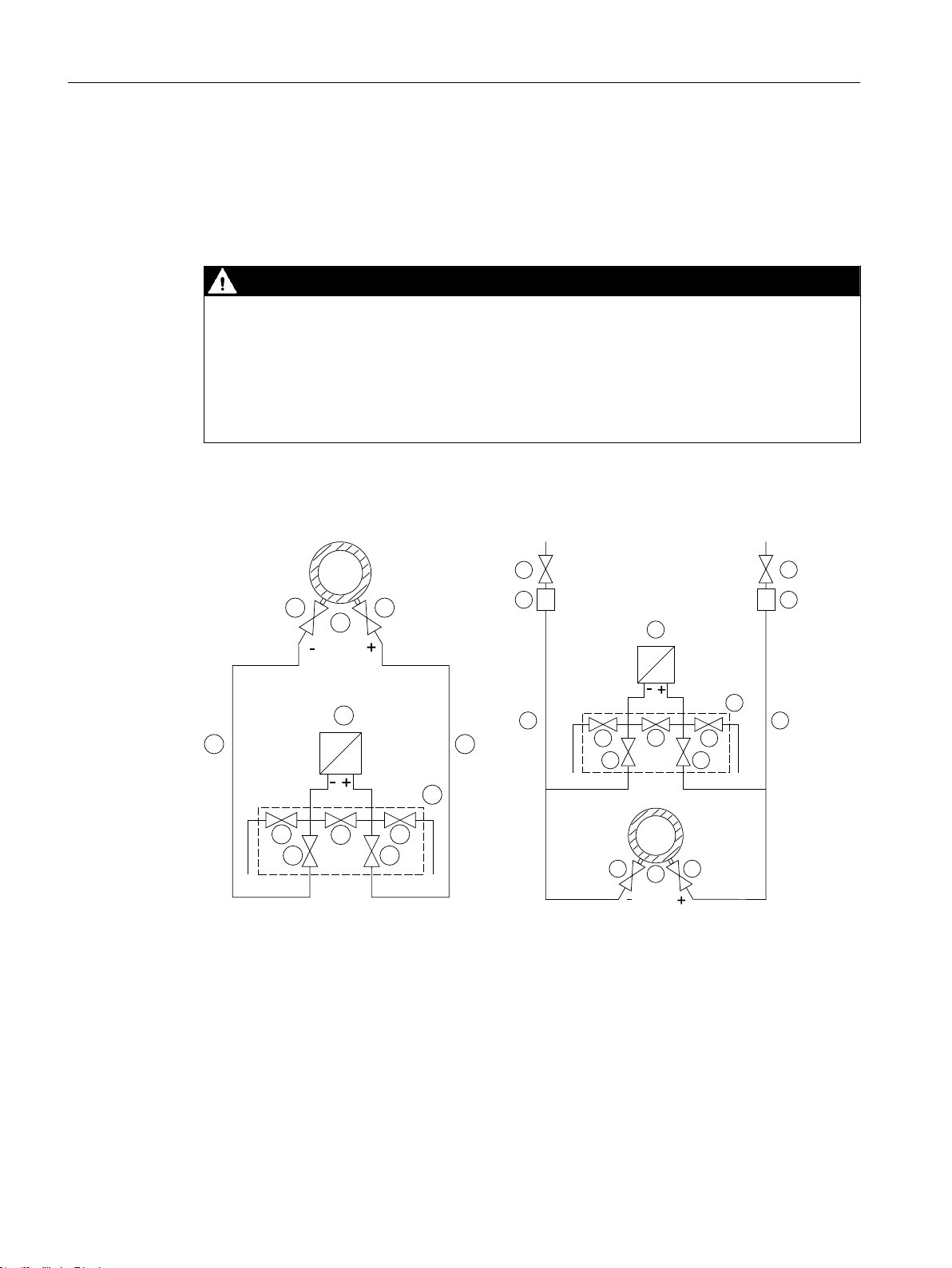
Commissioning
6.5 Differential pressure and flow rate
6.5.2 Commissioning for liquids
Requirement
All valves are closed.
DANGER
Toxic liquids
Danger of poisoning when the device is vented.
If toxic process media are measured with this device, toxic liquids can escape when the device
is vented.
● Before venting, make sure there is no liquid in the device or take the necessary safety
precautions.
Procedure
Pressure transmitter below thedifferential
pressure transducer
① Pressure transmitter ⑦ Drain valves
② Stabilizing valve ⑧ Gas collector vessels (optional)
Pressure transmitter above the differential pressure
transducer
③, ④ Differential pressure valves ⑨ Differential pressure transducer
⑤ Differential pressure lines ⑩ Vent valves
⑥ Shut-off valves ⑪ 5-way valve manifold
50 Compact Operating Instructions, 09/2018, A5E38874562-AB
SITRANS P320/P420 with 4 to 20 mA/HART
Page 51

Commissioning
6.5 Differential pressure and flow rate
To commission the pressure transmitter for liquids, proceed as follows:
1. Open both the shut-off valves ⑥ at the pressure tapping point.
2. Open the stabilizing valve ②.
3. With pressure transmitters below the differential pressure transducer, partially open both
drain valves ⑦ one after the other until liquid emerges without bubbles.
In the case of a pressure transmitter above the differential pressure transducer, partially
open both vent valves ⑩ one after the other until liquid emerges without bubbles.
4. Close both drain valves ⑦ or vent valves ⑩.
5. Partially open the differential pressure valve ③ and the vent valve (sealing plug with vent
valve) on the positive side of the pressure transmitter until liquid escapes without bubbles.
6. Close the vent valve (sealing plug with vent valve).
7. Partially open the vent valve (sealing plug with vent valve) on the negative side of the
pressure transmitter until liquid escapes without bubbles.
8. Close the differential pressure valve ③.
9. Partially open the differential pressure valve ④ until liquid escapes without bubbles.
10.Close the differential pressure valve.
11.Close the vent valve (sealing plug with vent valve) on the negative side of the pressure
transmitter.
12.Open the differential pressure valve ③ with half a revolution.
13.For a lower range value of 0 bar, check the zero point (4 mA) and correct the lower range
value if it is different.
14.Close the stabilizing valve ②.
15.Open the differential pressure valves (③ and ④) completely.
6.5.3 Commissioning with vapor
Requirement
All valves are closed.
WARNING
Hot vapor
Danger of injury or damage to device.
If the shut-off valves ⑥ and the differential pressure valve ③ are both open and the stabilizing
valve ② is then opened, the pressure transmitter ① can be damaged by the flow of vapor.
● Follow the specified procedure for commissioning.
SITRANS P320/P420 with 4 to 20 mA/HART
Compact Operating Instructions, 09/2018, A5E38874562-AB 51
Page 52
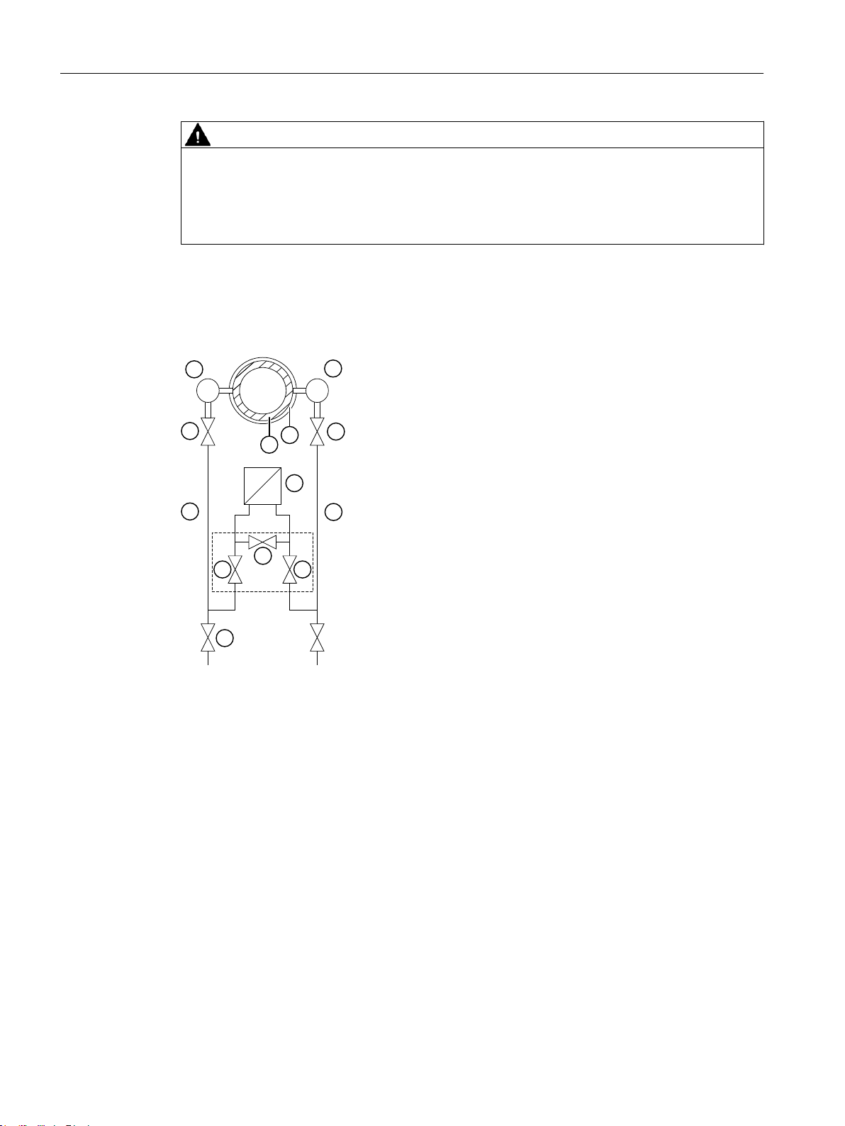
Commissioning
6.5 Differential pressure and flow rate
WARNING
Hot vapor
Danger of injury.
You can briefly open the drain valves ⑦ to clean the line. Hot vapor can escape in the process.
● Only open the drain valves ⑦ briefly, and close them again before vapor escapes.
Procedure
① Pressure transmitter ⑦ Drain valves
② Stabilizing valve ⑧ Condensate pots
③,
Differential pressure valves ⑨ Differential pressure transducer/Orifice plate
④
⑤ Differential pressure lines ⑩ Insulation
⑥ Shut-off valves ⑪ 3-way valve manifold
To commission the pressure transmitter for vapor, proceed as follows:
52 Compact Operating Instructions, 09/2018, A5E38874562-AB
1. Open both the shut-off valves ⑥ at the pressure tapping point.
2. Open the stabilizing valve ②.
3. Wait until the steam in the differential pressure lines ⑤ and in the equalizing vessels ⑧
has condensed.
4. Partially open the differential pressure valve ③ and the vent valve (sealing plug with vent
valve) on the positive side of the pressure transmitter until condensate escapes without
bubbles.
5. Close the vent valve (sealing plug with vent valve).
SITRANS P320/P420 with 4 to 20 mA/HART
Page 53

Commissioning
6.5 Differential pressure and flow rate
6. Partially open the vent valve (sealing plug with vent valve) on the negative side of the
pressure transmitter until condensate escapes without bubbles.
7. Close the differential pressure valve ③.
8. Partially open the differential pressure valve ④ until condensate escapes without bubbles.
9. Close the vent valve with blanking plug on the negative side ①.
10.Close the differential pressure valve.
11.Open the differential pressure valve ③ by half a revolution.
12.For the start of scale value 0 bar, check the zero point (4 mA).
If the differential pressure lines ⑤ have equally high condensate columns with the same
temperature, the measurement result is error-free. Otherwise, repeat the zero-point
adjustment.
13.Close the stabilizing valve ②.
14.Fully open the differential pressure valves ③ and ④.
Cleaning process cable
1. To clean the line, briefly open the drain valves ⑦.
2. Close the drain valve ⑦ before vapor escapes.
SITRANS P320/P420 with 4 to 20 mA/HART
Compact Operating Instructions, 09/2018, A5E38874562-AB 53
Page 54

Commissioning
6.5 Differential pressure and flow rate
SITRANS P320/P420 with 4 to 20 mA/HART
54 Compact Operating Instructions, 09/2018, A5E38874562-AB
Page 55
Service and maintenance
7.1 Basic safety instructions
The device is maintenance-free. However, a periodic inspection according to pertinent
directives and regulations must be carried out.
An inspection can include check of:
● Ambient conditions
● Seal integrity of the process connections, cable entries, and cover screws
● Reliability of power supply, lightning protection, and grounds
WARNING
Use of a computer in a hazardous area
If the interface to the computer is used in the hazardous area, there is a risk of explosion.
● Ensure that the atmosphere is explosion-free (hot work permit).
WARNING
7
Dust layers above 5 mm
Risk of explosion in hazardous areas. Device may overheat due to dust build up.
● Remove dust layers in excess of 5 mm.
CAUTION
Releasing button lock
Improper modification of parameters could influence process safety.
● Make sure that only authorized personnel may cancel the button locking of devices for
safety-related applications.
NOTICE
Penetration of moisture into the device
Device damage.
● Make sure when carrying out cleaning and maintenance work that no moisture penetrates
the inside of the device.
SITRANS P320/P420 with 4 to 20 mA/HART
Compact Operating Instructions, 09/2018, A5E38874562-AB 55
Page 56
Service and maintenance
7.3 Maintenance and repair work
7.2 Cleaning
Cleaning the enclosure
● Clean the outside of the enclosure with the inscriptions and the display window using a
cloth moistened with water or a mild detergent.
● Do not use any aggressive cleansing agents or solvents, e.g. acetone. Plastic parts or the
painted surface could be damaged. The inscriptions could become unreadable.
NOTICE
Improper cleaning of diaphragm
Device damage. The diaphragm can be damaged.
● Do not use sharp or hard objects to clean the diaphragm.
7.2.1 Servicing the remote seal measuring system
The remote seal measuring system usually does not need servicing.
If the mediums are contaminated, viscous or crystallized, it could be necessary to clean the
diaphragm from time to time. Use only a suitable solvent to remove the deposits from the
diaphragm. Do not use corrosive cleaning agents. Prevent the diaphragm from getting
damaged due to sharp-edged tools.
7.3 Maintenance and repair work
WARNING
Impermissible repair and maintenance of the device
● Repair and maintenance must be carried out by Siemens authorized personnel only.
WARNING
Impermissible repair of explosion protected devices
Risk of explosion in hazardous areas
● Repair must be carried out by Siemens authorized personnel only.
SITRANS P320/P420 with 4 to 20 mA/HART
56 Compact Operating Instructions, 09/2018, A5E38874562-AB
Page 57

CAUTION
Hot surfaces
Risk of burns during maintenance work on parts having surface temperatures exceeding
70 °C (158 °F).
● Take corresponding protective measures, for example by wearing protective gloves.
● After carrying out maintenance, remount touch protection measures.
7.3.1 Defining the maintenance interval
WARNING
No maintenance interval has been defined
Device failure, device damage, and risk of injury.
● Define a maintenance interval for recurring tests depending on the use of the device and
your own experience.
● The maintenance interval will vary from site to site depending on corrosion resistance.
Service and maintenance
7.3 Maintenance and repair work
WARNING
Maintenance during continued operation in a hazardous area
There is a risk of explosion when carrying out repairs and maintenance on the device in a
hazardous area.
● Isolate the device from power.
- or -
● Ensure that the atmosphere is explosion-free (hot work permit).
WARNING
Impermissible accessories and spare parts
Risk of explosion in areas subject to explosion hazard.
● Only use original accessories or original spare parts.
● Observe all relevant installation and safety instructions described in the instructions for
the device or enclosed with the accessory or spare part.
SITRANS P320/P420 with 4 to 20 mA/HART
Compact Operating Instructions, 09/2018, A5E38874562-AB 57
Page 58
Service and maintenance
7.3 Maintenance and repair work
WARNING
Hot, toxic or corrosive process media
Risk of injury during maintenance work.
When working on the process connection, hot, toxic or corrosive process media could be
released.
● As long as the device is under pressure, do not loosen process connections and do not
remove any parts that are pressurized.
● Before opening or removing the device ensure that process media cannot be released.
WARNING
Improper connection after maintenance
Risk of explosion in areas subject to explosion hazard.
● Connect the device correctly after maintenance.
● Close the device after maintenance work.
Refer to Connecting the device (Page 39).
7.3.2 Checking the gaskets
Inspect the seals at regular intervals
Note
Incorrect seal changes
Incorrect measured values will be displayed. Changing the seals in a process flange of a
differential pressure measuring cell can alter the start-of-scale value.
● Changing seals in devices with differential pressure measuring cells may only be carried
out by personnel authorized by Siemens.
Note
Using the wrong seals
Using the wrong seals with flush-mounted process connections can cause measuring errors
and/or damage the diaphragm.
● Always use seals which comply with the process connection standards or are
recommended by Siemens.
1. Clean the enclosure and seals.
2. Check the enclosure and the seals for cracks and damage.
3. If necessary, lubricate the seals or replace them.
SITRANS P320/P420 with 4 to 20 mA/HART
58 Compact Operating Instructions, 09/2018, A5E38874562-AB
Page 59

7.3.3 Diagnostics messages
Diagnostics (e.g. sensor break) detected by the internal self-test are signaled as follows:
● Display: NE107 symbol and diagnostics ID
● Current output (4-20 mA): Fault current
● HART: Diagnostic alarm via the remote operation
For a complete list of diagnostic messages and their meaning, refer to the "Diagnostics and
Troubleshooting" section in the detailed operating instructions.
7.4 Return procedure
Enclose the bill of lading, return document and decontamination certificate in a clear plastic
pouch and attach it firmly to the outside of the packaging. Any devices/replacement parts which
are returned without a decontamination declaration will be cleaned at your expense before
further processing. For further details, refer to the operating instructions.
Service and maintenance
7.5 Disposal
See also
Decontamination declaration (http://www.siemens.com/sc/declarationofdecontamination)
Return document (http://www.siemens.com/processinstrumentation/returngoodsnote)
7.5 Disposal
Note
Special disposal required
The device includes components that require special disposal.
● Dispose of the device properly and environmentally through a local waste disposal
contractor.
Devices described in this manual should be recycled. They may not be
disposed of in the municipal waste disposal services according to the Di‐
rective 2012/19/EC on waste electronic and electrical equipment (WEEE).
Devices can be returned to the supplier within the EC, or to a locally ap‐
proved disposal service for eco-friendly recycling. Observe the specific reg‐
ulations valid in your country.
Further information about devices containing batteries can be found at: In‐
formation on battery/product return (WEEE) (https://
support.industry.siemens.com/cs/document/109479891/)
SITRANS P320/P420 with 4 to 20 mA/HART
Compact Operating Instructions, 09/2018, A5E38874562-AB 59
Page 60

Service and maintenance
7.5 Disposal
SITRANS P320/P420 with 4 to 20 mA/HART
60 Compact Operating Instructions, 09/2018, A5E38874562-AB
Page 61

Technical data
8.1 Input
8.1.1 Gauge pressure
Gauge pressure input
Measured variable Gauge pressure
Measuring span (continuous‐
ly adjustable) or measuring
range, max. operating pres‐
sure (in accordance with
2014/68/EU Pressure Equip‐
ment Directive) and max. test
pressure (in accordance with
DIN 16086) (for oxygen
measurement, max. 100 bar
and 60 °C ambient tempera‐
ture/process temperature)
Measuring span Maximum permissible
8.3 … 250 mbar
0.83 ... 25 kPa
0.12 … 3.6 psi
0.01 … 1 bar
1 ... 100 kPa
0.15 … 14.5 psi
0.04 … 4 bar
4 ... 400 kPa
0.58 … 58 psi
0.16 … 16 bar
0.016 ... 1.6 MPa
2.3 … 232 psi
0.63 … 63 bar
0.063 ... 6.3 MPa
9.1 … 914 psi
1.6 … 160 bar
0.16 ... 16 MPa
23 … 2321 psi
4 … 400 bar
0.4 ... 40 MPa
58 … 5802 psi
7 … 700 bar
0.7 ... 70 MPa
102 ... 10153 psi
operating pressure MAWP
(PS)
4 bar
0.4 MPa
58 psi
6 bar
0.6 MPa
87 psi
20 bar
2 MPa
290 psi
45 bar
4.5 MPa
652 psi
80 bar
8 MPa
1160 psi
240 bar
24 MPa
3480 psi
400 bar
40 MPa
5802 psi
800 bar
80 MPa
11603 psi
8
Maximum test
pressure
6 bar
0.6 MPa
87 psi
9 bar
0.9 MPa
130 psi
30 bar
3 MPa
435 psi
70 bar
7 MPa
1015 psi
120 bar
12 MPa
1740 psi
360 bar
36 MPa
5221 psi
600 bar
60 MPa
8702 psi
800 bar
80 MPa
11603 psi
Gauge pressure measuring limits
Lower measuring limit1)
● Measuring cell with silicone oil filling
SITRANS P320/P420 with 4 to 20 mA/HART
Compact Operating Instructions, 09/2018, A5E38874562-AB 61
30 mbar a/3 kPa a/0.44 psi a
Page 62

Technical data
8.1 Input
Gauge pressure measuring limits
● Measuring cell with inert oil
● Measuring cell with FDA-compliant oil
Upper measuring limit 100% of max. range (for oxygen measurement: max. 100 bar/10 MPa/
Start of scale value Between the measuring limits (continuously adjustable)
1)
For 250 mbar/25 kPa/3.6 psi measuring cells, the low measuring limit is 750 mbar a/75 kPa a/
30 mbar a/3 kPa a/0.44 psi a
100 mbar a/10 kPa a/1.45 psi a
1450 psi and 60 °C ambient temperature/medium temperature)
10.8 psi a. The measuring cell is vacuum-tight down to 30 mbar a/3 kPa a/0.44 psi a.
8.1.2 Gauge pressure with front-flush diaphragm
Gauge pressure input with front-flush diaphragm
Measured variable Gauge pressure
Measuring span (continuous‐
ly adjustable) or measuring
range, max. operating pres‐
sure and max. test pressure
1)
The MAWP value of the pressure transmitter can be lower than the PN value of the mounting
flange and vice versa. To determine the maximum permissible operating pressure and the
maximum permissible test pressure, use the lowest value as reference.
Measuring span Maximum permissible
operating pressure MAWP
(PS)
0.01 … 1 bar
1 ... 100 kPa
0.15 … 14.5 psi
0.04 … 4 bar
4 ... 400 kPa
0.58 … 58 psi
0.16 … 16 bar
0.016 ... 1.6 MPa
2.3 … 232 psi
0.6 … 63 bar
0.063 ... 6.3 MPa
9.1 … 914 psi
Refer to the information on the nameplate of the pressure
transmitter and the data on the mounting flange
Maximum test
pressure
1)
Gauge pressure measuring limits with front-flush diaphragm
Lower measuring limit
● Measuring cell with silicone oil filling
● Measuring cell with inert oil
● Measuring cell with FDA-compliant oil
Upper measuring limit 100% of max. range
100 mbar a/10 kPa a/1.45 psi a
100 mbar a/10 kPa a/1.45 psi a
100 mbar a/10 kPa a/1.45 psi a
SITRANS P320/P420 with 4 to 20 mA/HART
62 Compact Operating Instructions, 09/2018, A5E38874562-AB
Page 63

8.1.3 Gauge pressure from the differential pressure series
Gauge pressure input from the differential pressure series
Measured variable Gauge pressure and differential pressure
Measuring span (continuous‐
ly adjustable) and maximum
operating pressure (accord‐
ing to 2014/68/EU Pressure
Equipment Directive)
Measuring span Maximum permissible
operating pressure
MAWP (PS)
1 ... 20 mbar
0.1 ... 2 kPa
0.4015 … 8.031 inH2O
1 ... 60 mbar
0.1 ... 6 kPa
0.4015 … 24.09 inH2O
2.5 ... 250 mbar
0.2 ... 25 kPa
1.004 … 100.4 inH2O
6 ... 600 mbar
0.6 ... 60 kPa
2.409 … 240.9 inH2O
16 ... 1600 mbar
1.6 ... 160 kPa
6.424 … 642.4 inH2O
50 ... 5000 mbar
5 ... 500 kPa
20.08 … 2008 inH2O
0.3 … 30 bar
0.03 ... 3 MPa
4.35 … 435 psi
5 … 100 bar
0.5 ... 10 MPa
76.9 … 1450 psi
160 bar
16 MPa
2320 psi
160 bar
16 MPa
2320 psi
160 bar
16 MPa
2320 psi
160 bar
16 MPa
2320 psi
160 bar
16 MPa
2320 psi
160 bar
16 MPa
2320 psi
160 bar
16 MPa
2320 psi
160 bar
16 MPa
2320 psi
Technical data
8.1 Input
Max. permissible
test pressure
240 bar
24 MPa
3480 psi
240 bar
24 MPa
3480 psi
240 bar
24 MPa
3480 psi
240 bar
24 MPa
3480 psi
240 bar
24 MPa
3480 psi
240 bar
24 MPa
3480 psi
240 bar
24 MPa
3480 psi
240 bar
24 MPa
3480 psi
Gauge pressure measuring limits from differential pressure
series
Lower measuring limit
● Measuring cell with silicone oil filling
● Measuring cell with inert oil
● Measuring cell with FDA-compliant oil
Upper measuring limit 100% of max. range (for oxygen measurement: max. 100 bar/
Start of scale value Between the measuring limits (continuously adjustable)
SITRANS P320/P420 with 4 to 20 mA/HART
Compact Operating Instructions, 09/2018, A5E38874562-AB 63
30 mbar a/3 kPa a/0.44 psi a
30 mbar a/3 kPa a/0.44 psi a
100 mbar a/10 kPa a/1.45 psi a
10 MPa/1450 psi and 60 °C ambient temperature/medium
temperature)
Page 64

Technical data
8.1 Input
8.1.4 Absolute pressure from the gauge pressure series
Absolute pressure input from the gauge pressure series
Measured variable Absolute pressure
Measuring span (continuous‐
ly adjustable) or measuring
range, max. operating pres‐
sure (in accordance with
2014/68/EU Pressure Equip‐
ment Directive) and max. test
pressure (in accordance with
DIN 16086)
Measuring span Maximum permissible
operating pressure MAWP
(PS)
8.3 … 250 mbar a
0.83 ... 25 kPa a
3 … 100 inH2O a
43 … 1300 mbar a
4.3 ... 130 kPa a
17 … 525 inH2O a
166 … 5000 mbar a
16.6 ... 500 kPa a
2.41 … 72.5 psi a
1 … 30 bar a
0.1 ... 3 MPa a
14.5 … 435 psi a
5.3 … 160 bar a
0.53 ... 16 MPa a
77 … 2321 psi a
13.3 … 400 bar a
1.3 ... 40 MPa a
192 ... 5801 psi a
23.3 … 700 bar a
2.3 ... 70 MPa a
337 ... 10152 psi a
4 bar a
0.4 MPa a
58 psi a
6.6 bar a
0.66 MPa a
95 psi a
20 bar a
2 MPa a
290 psi a
65 bar a
6.5 MPa a
942 psi a
240 bar a
24 MPa a
3480 psi a
400 bar a
40 MPa a
5801 psi a
800 bar a
80 MPa a
11603 psi a
Maximum test
pressure
6 bar a
0.6 MPa a
87 psi a
10 bar a
1 MPa a
145 psi a
30 bar a
3 MPa a
435 psi a
100 bar a
10 MPa a
1450 psi a
380 bar a
38 MPa a
5511 psi a
600 bar a
60 MPa a
8702 psi a
800 bar a
80 MPa a
11603 psi a
Absolute pressure measuring limits from
gauge pressure series
Lower measuring limit
● Measuring cell with silicone oil filling
● Measuring cell with inert oil
For process temperature
-20 °C < ϑ ≤ 60 °C (-4 °F < ϑ
≤ +140 °F)
For process temperature
60 °C < ϑ ≤ 100 °C (max.
85 °C for measuring cell
30 bar) (140 °F < ϑ ≤ 212 °F
(max. 185 °F for measuring
cell 435 psi))
0 mbar a/kPa a/psi a
30 mbar a/3 kPa a/0.44 psi a
30 mbar a + 20 mbar a • (ϑ - 60 °C)/°C
3 kPa a + 2 kPa a • (ϑ - 60 °C)/°C
0.44 psi a + 0.29 psi a • (ϑ - 140 °F)/°F
SITRANS P320/P420 with 4 to 20 mA/HART
64 Compact Operating Instructions, 09/2018, A5E38874562-AB
Page 65

Technical data
8.1 Input
Absolute pressure measuring limits from
gauge pressure series
Upper measuring limit 100% of max. range (for oxygen measurement: max. 100 bar/10 MPa/
Lower range value Between the measuring limits (continuously adjustable)
1450 psi and 60 °C ambient temperature/medium temperature)
8.1.5 Absolute pressure with front-flush diaphragm
Absolute pressure with front-flush diaphragm
Measured variable Absolute pressure
Measuring span (continuous‐
ly adjustable) or measuring
range, max. operating pres‐
sure and max. test pressure
1)
The MAWP value of the pressure transmitter can be lower than the PN value of the mounting
flange and vice versa. To determine the maximum permissible operating pressure and the
maximum permissible test pressure, use the lowest value as reference.
Measuring span Maximum permissible
operating pressure MAWP
(PS)
43 … 1300 mbar a
4.3 ... 130 kPa a
17 … 525 inH2O a
166 … 5000 mbar a
16.6 ... 500 kPa a
2.41 … 72.5 psi a
1 … 30 bar a
0.1 ... 3 MPa a
14.5 … 435 psi a
Depending on the process connection, the measuring span may differ from these values
Refer to the information on the nameplate of the pressure
transmitter and the data on the mounting flange
Maximum test
pressure
1)
Absolute pressure measuring limits with front-flush diaphragm
Lower measuring limit
● Measuring cell with silicone oil filling
Upper measuring limit 100% of max. range
Lower range value Between the measuring limits (continuously adjustable)
SITRANS P320/P420 with 4 to 20 mA/HART
Compact Operating Instructions, 09/2018, A5E38874562-AB 65
0 mbar a/kPa a/psi a
Page 66

Technical data
8.1 Input
8.1.6 Absolute pressure from the differential pressure series
Absolute pressure input from the differential pressure series
Measured variable Absolute pressure
Measuring span (continuous‐
ly adjustable) and maximum
operating pressure (accord‐
ing to 2014/68/EU Pressure
Equipment Directive)
Measuring span Maximum permissible
operating pressure
MAWP (PS)
8.3 … 250 mbar a
0.83 ... 25 kPa a
3 … 100 inH2O a
43 … 1300 mbar a
4.3 ... 130 kPa a
17 … 525 inH2O a
166 … 5000 mbar a
16.6 ... 500 kPa a
2.41 … 72.5 psi a
1 … 30 bar a
0.1 ... 3 MPa a
14.5 … 435 psi a
5 … 100 bar a
0.5 ... 10 MPa a
76.9 … 1450 psi a
160 bar a
16 MPa a
2320 psi a
160 bar a
16 MPa a
2320 psi a
160 bar a
16 MPa a
2320 psi a
160 bar a
16 MPa a
2320 psi a
160 bar a
16 MPa a
2320 psi a
Max. permissible
test pressure
240 bar a
24 MPa a
3480 psi a
240 bar a
24 MPa a
3480 psi a
240 bar a
24 MPa a
3480 psi a
240 bar a
24 MPa a
3480 psi a
240 bar a
24 MPa a
3480 psi a
Absolute pressure measuring limits from dif‐
ferential pressure series
Lower measuring limit
● Measuring cell with silicone oil filling
● Measuring cell with inert liquid
For process temperature -20 °C <
ϑ ≤ 60 °C (-4 °F < ϑ ≤ +140 °F)
For process temperature 60 °C < ϑ
≤ 100 °C (max. 85 °C for measur‐
ing cell 30 bar) (140 °F < ϑ ≤ 212 °F
(max. 185 °F for measuring cell
435 psi))
Upper measuring limit 100% of max. range (for oxygen measurement: max. 100 bar/10 MPa/
Start of scale value Between the measuring limits (continuously adjustable)
0 mbar a/kPa a/psi a
30 mbar a/3 kPa a/0.44 psi a
30 mbar a + 20 mbar a • (ϑ - 60 °C)/°C
3 kPa a + 2 kPa a • (ϑ - 60 °C)/°C
0.44 psi a + 0.29 psi a • (ϑ - 140 °F)/°F
1450 psi and 60 °C ambient temperature/medium temperature)
SITRANS P320/P420 with 4 to 20 mA/HART
66 Compact Operating Instructions, 09/2018, A5E38874562-AB
Page 67

8.1.7 Differential pressure and flow
Differential pressure input and flow
Measured variable Differential pressure and flow
Measuring span (continuous‐
ly adjustable) and maximum
operating pressure (accord‐
ing to 2014/68/EU Pressure
Equipment Directive)
Measuring span Maximum permissible
1 ... 20 mbar
0.1 ... 2 kPa
0.4015 … 8.031 inH2O
1 ... 60 mbar
0.1 ... 6 kPa
0.4015 … 24.09 inH2O
2.5 ... 250 mbar
0.2 ... 25 kPa
1.004 … 100.4 inH2O
6 ... 600 mbar
0.6 ... 60 kPa
2.409 … 240.9 inH2O
16 ... 1600 mbar
1.6 ... 160 kPa
6.424 … 642.4 inH2O
50 ... 5000 mbar
5 ... 500 kPa
20.08 … 2008 inH2O
0.3 … 30 bar
0.03 ... 3 MPa
4.35 … 435 psi
2.5 ... 250 mbar
0.25 ... 25 kPa
1.004 … 100.4 inH2O
6 ... 600 mbar
0.6 ... 60 kPa
2.409 … 240.9 inH2O
16 ... 1600 mbar
1.6 ... 160 kPa
6.424 … 642.4 inH2O
50 ... 5000 mbar
5 ... 500 kPa
20.08 … 2008 inH2O
0.3 … 30 bar
0.03 ... 3 MPa
4.35 … 435 psi
operating pressure
MAWP (PS)
160 bar
16 MPa
2320 psi
160 bar
16 MPa
2320 psi
160 bar
16 MPa
2320 psi
160 bar
16 MPa
2320 psi
160 bar
16 MPa
2320 psi
160 bar
16 MPa
2320 psi
160 bar
16 MPa
2320 psi
420 bar
42 MPa
6091 psi
420 bar
42 MPa
6091 psi
420 bar
42 MPa
6091 psi
420 bar
42 MPa
6091 psi
420 bar
42 MPa
6091 psi
Technical data
8.1 Input
Max. permissible
test pressure
240 bar
24 MPa
3480 psi
240 bar
24 MPa
3480 psi
240 bar
24 MPa
3480 psi
240 bar
24 MPa
3480 psi
240 bar
24 MPa
3480 psi
240 bar
24 MPa
3480 psi
240 bar
24 MPa
3480 psi
630 bar
63 MPa
9137 psi
630 bar
63 MPa
9137 psi
630 bar
63 MPa
9137 psi
630 bar
63 MPa
9137 psi
630 bar
63 MPa
9137 psi
SITRANS P320/P420 with 4 to 20 mA/HART
Compact Operating Instructions, 09/2018, A5E38874562-AB 67
Page 68

Technical data
8.1 Input
Differential pressure and flow measuring limits
Lower measuring limit
● Measuring cell
with silicone oil
filling
● Measuring cell with inert oil
For process temperature -20 °C
For process temperature 60 °C
● Measuring cell
with FDAcompliant oil
Upper measuring
limit
Start of scale value Between the measuring limits (continuously adjustable)
-100% of maximum measuring range or 30 mbar a /3 kPa a /0.44 psi a
-100% of maximum measuring range or 30 mbar a /3 kPa a /0.44 psi a
< ϑ ≤ 60 °C (-4 °F < ϑ ≤ +140 °F)
-100% of maximum measuring range or 30 mbar a /3 kPa a /0.44 psi a
< ϑ ≤ 100 °C (max. 85 °C for
measuring cell 30 bar with
PN420) (140 °F < ϑ ≤ 212 °F
(max. 185 °F for measuring cell
435 psi))
For process temperature -10 °C
< ϑ ≤ 100 °C (-14 °F < ϑ
≤ +212 °F)
100% of max. range (for oxygen measurement: max. 100 bar/10 MPa/1450 psi and 60 °C ambient
temperature/medium temperature)
30 mbar a + 20 mbar a • (ϑ - 60 °C)/°C
3 kPa a + 2 kPa a • (ϑ - 60 °C)/°C
0.44 psi a + 0.29 psi a • (ϑ - 140 °F)/°F
-100% of maximum measuring range or 100 mbar a /10 kPa a /
14.5 psi a.
8.1.8 Level
Level input
Measured variable Level
Measuring span (continuous‐
ly adjustable) and maximum
operating pressure (accord‐
ing to 2014/68/EU Pressure
Equipment Directive)
Measuring span Maximum permissible
operating pressure
MAWP (PS)
25 ... 250 mbar
2.5 ... 25 kPa
10 … 100 inH2O
25 ... 600 mbar
2.5 ... 60 kPa
10 … 240 inH2O
53 … 1600 mbar
5.3 ... 160 kPa
21 … 640 inH2O
166 … 5000 mbar
16.6 ... 500 kPa
2.41 … 72.5 psi
See mounting flange
Max. permissible
test pressure
SITRANS P320/P420 with 4 to 20 mA/HART
68 Compact Operating Instructions, 09/2018, A5E38874562-AB
Page 69

Technical data
8.2 Measuring accuracy of SITRANS P320
Level measuring limits
Lower measuring limit
Measuring cell with silicone oil
filling
Measuring cell with inert oil -100% of max. measuring range or 30 mbar a/3 kPa a/0.44 psi a depending
Measuring cell with FDA-com‐
pliant oil
Upper measuring limit 100% of max. range
Lower range value Between the measuring limits (continuously adjustable)
-100% of max. measuring range or 30 mbar a/3 kPa a/0.44 psi a depending
on the mounting flange
on the mounting flange
-100% of maximum measuring range or 100 mbar a /10 kPa a /1.45 psi a
8.2 Measuring accuracy of SITRANS P320
8.2.1 Reference conditions
● According to EN 60770-1/IEC 61298-1
● Rising characteristic curve
● Lower range value 0 bar/kPa/psi
● Seal diaphragm stainless steel
● Measuring cell with silicone oil filling
● Room temperature 25 °C (77 °F)
8.2.2 Effect of auxiliary power supply
0.005% per 1 V (in percent per change in voltage)
8.2.3 Gauge pressure
Conformity error at limit point setting, including hysteresis and repeatability - gauge pressure
Measuring span ratio r (spread, Turn-Down) r = max. measuring span/set measuring span and nominal
measuring range
● Linear characteristic curve
250 mbar/25 kPa/3.6 psi ≤ 0.075% ≤ (0.008 • r + 0.055)%
● Linear characteristic curve
r ≤ 1.25 1.25 < r ≤ 30
r ≤ 5 5 < r ≤ 100
SITRANS P320/P420 with 4 to 20 mA/HART
Compact Operating Instructions, 09/2018, A5E38874562-AB 69
Page 70

Technical data
8.2 Measuring accuracy of SITRANS P320
Conformity error at limit point setting, including hysteresis and repeatability - gauge pressure
1 bar/100 kPa/14.5 psi
4 bar/400 kPa/58 psi
16 bar/1.6 MPa/232 psi
63 bar/6.3 MPa/914 psi
160 bar/16 MPa/12321 psi
● Linear characteristic
curve
400 bar/40 MPa/5802 psi
Effect of ambient temperature - gauge pressure
In percent per 28 °C (50 °F)
250 mbar/25 kPa/3.6 psi ≤ (0.16 • r + 0.1)%
1 bar/100 kPa/14.5 psi ≤ (0.05 • r + 0.1)%
4 bar/400 kPa/58 psi
16 bar/1.6 MPa/232 psi
63 bar/6.3 MPa/914 psi
160 bar/16 MPa/2321 psi
400 bar/40 MPa/5802 psi
700 bar/70 MPa/10152 psi ≤ (0.08 • r + 0.16)%
r ≤ 3 3 < r ≤ 100
700 bar/70 MPa/10152 psi
≤ 0.065% ≤ (0.004 • r + 0.045)%
≤ 0.075% 0.005 • r + 0.05
≤ (0.025 • r + 0.125)%
Long-term stability at ±30 °C (±54 °F) - gauge pressure
250 mbar/25 kPa/3.6 psi Per year ≤ (0.25 • r)%
1 bar/100 kPa/14.5 psi In 5 years ≤ (0.25 • r)%
In 10 years ≤ (0.35 • r)%
4 bar/400 kPa/58 psi
16 bar/1.6 MPa/232 psi
63 bar/6.3 MPa/914 psi
160 bar/16 MPa/2321 psi
400 bar/40 MPa/5802 psi
700 bar/70 MPa/10152 psi In 5 years ≤ (0.25 • r)%
Step response time T63 (without electrical damping) - gauge pressure
Approx. 0.105 s
Effect of mounting position - gauge pressure
≤ 0.05 mbar/0.005 kPa/0.000725 psi per 10° incline
(correct the zero point with position error compensation)
In 5 years ≤ (0.125 • r)%
In 10 years ≤ (0.15 • r)%
In 10 years ≤ (0.35 • r)%
SITRANS P320/P420 with 4 to 20 mA/HART
70 Compact Operating Instructions, 09/2018, A5E38874562-AB
Page 71

Technical data
8.2 Measuring accuracy of SITRANS P320
8.2.4 Gauge pressure from the differential pressure series
Conformity error at limit point setting, including hysteresis and repeatability - gauge pressure from the differential pressure
series
Measuring span ratio r (spread, Turn-Down) r = max. measuring span/set measuring span and
nominal measuring range
● Linear characteristic curve
20 mbar/2 kPa/8.031 inH2O ≤ 0.075% ≤ (0.005 • r + 0.05)%
● Linear characteristic curve
60 mbar/6 kPa/24.09 inH2O ≤ 0.075% ≤ (0.005 • r + 0.05)%
● Linear characteristic curve
250 mbar/25 kPa/3.6 psi
● Linear characteristic curve
≤ 0.1% ≤ 0.2%
r ≤ 5 5 < r ≤ 60
600 mbar/60 kPa/240.9 inH2O
1600 mbar/160 kPa/642.4 inH2O
5000 mbar/500 kPa/2008 inH2O
30 bar/3 MPa/435 psi
100 bar/10 MPa/1450.3 psi r ≤ 10 10 < r ≤ 30
r ≤ 5 5 < r ≤ 20
r ≤ 5 5 < r ≤ 100
≤ 0.065% ≤ (0.004 • r + 0.045)%
Effect of ambient temperature - gauge pressure from differential pressure series
In percent per 28 °C (50 °F)
20 mbar/2 kPa/8.031 inH2O ≤ (0.15 • r + 0.1)%
60 mbar/6 kPa/24.09 inH2O ≤ (0.075 • r + 0.1)%
250 mbar/25 kPa/3.6 psi
600 mbar/60 kPa/240.9 inH2O
1600 mbar/160 kPa/642.4 inH2O
5000 mbar/500 kPa/2008 inH2O
30 bar/3 MPa/435 psi
100 bar/10 MPa/1450.3 psi ≤ (0.08 • r + 0.16)
Long-term stability at ±30 °C (±54 °F) - gauge pressure from differential pressure series
20 mbar/2 kPa/8.031 inH2O Per year ≤ (0.2 • r)%
60 mbar/6 kPa/24.09 inH2O In 5 years ≤ (0.25 • r)%
250 mbar/25 kPa/3.6 psi
600 mbar/60 kPa/240.9 inH2O
1600 mbar/160 kPa/642.4 inH2O
5000 mbar/500 kPa/2008 inH2O
30 bar/3 MPa/435 psi In 5 years ≤ (0.25 • r)%
100 bar/10 MPa/1450.3 psi In 5 years ≤ (0.25 • r)%
≤ (0.025 • r + 0.125)%
In 5 years ≤ (0.125 • r)%
In 10 years ≤ (0.15 • r)%
In 10 years ≤ (0.35 • r)%
SITRANS P320/P420 with 4 to 20 mA/HART
Compact Operating Instructions, 09/2018, A5E38874562-AB 71
Page 72

Technical data
8.2 Measuring accuracy of SITRANS P320
Step response time T63 (without electrical damping) - gauge pressure from differential pressure series
20 mbar/2 kPa/8.031 inH2O Approx. 0.160 s
60 mbar/6 kPa/24.09 inH2O Approx. 0.150 s
250 mbar/25 kPa/3.6 psi
600 mbar/60 kPa/240.9 inH2O
1600 mbar/160 kPa/642.4 inH2O
5000 mbar/500 kPa/2008 inH2O
30 bar/3 MPa/435 psi
100 bar/10 MPa/1450.3 psi Approx. 0.145 s
Effect of mounting position - gauge pressure from differential pressure series
≤ 0.7 mbar/0.007 kPa/0.01015266 psi per 10° incline
(correct the zero point with position error compensation)
Approx. 0.135 s
8.2.5 Absolute pressure from gauge and differential pressure series
Conformity error at limit point setting, including hysteresis and repeatability - absolute pressure from gauge and differential
pressure series
Measuring span ratio r (spread, Turn-Down) r = max. measuring span/set measuring span and nominal
measuring range
● Linear characteristic curve
All measuring cells ≤ 0.1% ≤ 0.2%
Effect of ambient temperature - absolute pressure from gauge and differential pressure series
In percent per 28 °C (50 °F)
250 mbar/25 kPa/3.6 psi ≤ (0.15 • r + 0.1)
1300 mbar a/130 kPa a/18.8 psi a
5 bar a/500 kPa a/72.5 psi a
30 bar a/3000 kPa a/435 psi a
100 bar a/10 MPa a/1450.3 psi a
160 bar a/16 MPa a/2321 psi a
400 bar a/40 MPa a/5802 psi a
700 bar a/70 MPa a/10152.6 psi a
r ≤ 10 10 < r ≤ 30
≤ (0.08 • r + 0.16)
Long-term stability at ±30 °C (±54 °F) - absolute pressure from gauge and differential pressure series
In 5 years ≤ (0.25 • r)%
SITRANS P320/P420 with 4 to 20 mA/HART
72 Compact Operating Instructions, 09/2018, A5E38874562-AB
Page 73

Technical data
8.2 Measuring accuracy of SITRANS P320
Step response time T63 (without electrical damping) - absolute pressure from gauge and differential pressure series
Gauge pressure series
All measuring cells Approx. 0.105 s
Differential pressure series
250 mbar/25 kPa/3.6 psi Approx. 0.195 s
1300 mbar a/130 kPa a/18.8 psi a
5 bar a/500 kPa a/72.5 psi a
30 bar a/3000 kPa a/435 psi a
100 bar a/10 MPa a/1450.3 psi a
Effect of mounting position - absolute pressure from gauge and differential pressure series
In pressure per change of angle
● For absolute pressure (from the gauge pressure series): ≤ 0.05 mbar/0.005 kPa/
0.000725 psi per 10° incline
● For absolute pressure (from the differential pressure series): 0.7 mbar/0.07 kPa/
0.001015 psi per 10° incline
(zero-point correction is possible using the zero point adjustment)
Approx. 0.145 s
8.2.6 Absolute pressure with front-flush diaphragm
Conformity error at limit point setting, including hysteresis and repeatability
Measuring span ratio r (spread, Turn-Down) r = max. measuring span/set measuring span and nominal
measuring range
Linear characteristic curve r ≤ 10 10 < r ≤ 30
All measuring cells ≤ 0.2% ≤ 0.4%
Effect of ambient temperature
In percent per 28 °C (50 °F)
All measuring cells ≤ (0.16 • r + 0.24)
Long-term stability at ±30 °C (±54 °F)
All measuring cells In 5 years ≤ (0.25 • r)%
Step response time T63 (without electrical damping)
Approx. 0.105 s
SITRANS P320/P420 with 4 to 20 mA/HART
Compact Operating Instructions, 09/2018, A5E38874562-AB 73
Page 74

Technical data
8.2 Measuring accuracy of SITRANS P320
Effect of mounting position
In pressure per change of angle
0.04 kPa/0.4 mbar/0.006 psi per 10° incline
(zero-point correction is possible with position error compen‐
sation)
8.2.7 Gauge pressure with front-flush diaphragm
Conformity error at limit point setting, including hysteresis and repeatability - gauge pressure with front-flush diaphragm
Measuring span ratio r (spread, Turn-Down) r = max. measuring span/set measuring span and nominal
measuring range
● Linear characteristic curve
1 bar/100 kPa/14.5 psi
4 bar/400 kPa/58 psi
16 bar/1.6 MPa/232 psi
63 bar/6.3 MPa/914 psi
r ≤ 5 5 < r ≤ 100
≤ 0.075% ≤ (0.005 • r + 0.05)%
Effect of ambient temperature - gauge pressure with front-flush diaphragm
In percent per 28 °C (50 °F)
1 bar/100 kPa/14.5 psi
4 bar/400 kPa/58 psi
16 bar/1.6 MPa/232 psi
63 bar/6.3 MPa/914 psi
Long-term stability at ±30 °C (±54 °F) - gauge pressure with front-flush diaphragm
1 bar/100 kPa/14.5 psi
4 bar/400 kPa/58 psi
16 bar/1.6 MPa/232 psi
63 bar/6.3 MPa/914 psi
Step response time T63 (without electrical damping) - gauge pressure with front-flush diaphragm
Approx. 0.105 s
Effect of mounting position - gauge pressure with front-flush diaphragm
≤ 0.4 mbar/0.04 kPa/0.006 psi per 10° incline
(zero-point correction is possible with position error compen‐
sation)
≤ (0.08 • r + 0.16)%
In 5 years ≤ (0.25 • r)%
In 5 years ≤ (0.125 • r)%
SITRANS P320/P420 with 4 to 20 mA/HART
74 Compact Operating Instructions, 09/2018, A5E38874562-AB
Page 75

Technical data
8.2 Measuring accuracy of SITRANS P320
8.2.8 Differential pressure and flow
Conformity error at limit point setting, including hysteresis and repeatability - differential pressure and flow
Measuring span ratio r (spread, Turn-Down) r = max. measuring span/set measuring span and nomi‐
nal measuring range
Linear characteristic curve r ≤ 5 5 < r ≤ 20
20 mbar/2 kPa/0.29 psi ≤ 0.075% ≤ (0.005 • r + 0.05)%
Linear characteristic curve r ≤ 5 5 < r ≤ 60
60 mbar/6 kPa/0.87 psi ≤ 0.075% ≤ (0.005 • r + 0.05)%
Linear characteristic curve r ≤ 5 5 < r ≤ 100
250 mbar/25 kPa/3.63 psi
600 mbar/60 kPa/8.70 psi
1600 mbar/160 kPa/23.21 psi
5 bar/500 kPa/72.52 psi
30 bar/3 MPa/435.11 psi
Root extraction characteris‐
tic
Flow > 50%
20 mbar/2 kPa/0.29 psi ≤ 0.075% ≤ (0.005 • r + 0.05)%
Root extraction characteris‐
tic
Flow > 50%
60 mbar/6 kPa/0.87 psi ≤ 0.075% ≤ (0.005 • r + 0.05)%
Root extraction characteris‐
tic
Flow > 50%
250 mbar/25 kPa/3.63 psi
Root extraction characteris‐
tic
Flow 25 ... 50%
20 mbar/2 kPa/0.29 psi ≤ 0.15% ≤ (0.01 • r + 0.1)%
Root extraction characteris‐
tic
Flow 25 ... 50%
60 mbar/6 kPa/0.87 psi ≤ 0.15% ≤ (0.01 • r + 0.1)%
Root extraction characteris‐
tic
r ≤ 5 5 < r ≤ 20
r ≤ 5 5 < r ≤ 60
r ≤ 5 5 < r ≤ 100
600 mbar/60 kPa/8.70 psi
1600 mbar/160 kPa/23.21 psi
5 bar/500 kPa/72.52 psi
30 bar/3 MPa/435.11 psi
r ≤ 5 5 < r ≤ 20
r ≤ 5 5 < r ≤ 60
r ≤ 5 5 < r ≤ 100
≤ 0.065% ≤ (0.004 • r + 0.045)%
≤ 0.065% ≤ (0.004 • r + 0.045)%
SITRANS P320/P420 with 4 to 20 mA/HART
Compact Operating Instructions, 09/2018, A5E38874562-AB 75
Page 76

Technical data
8.2 Measuring accuracy of SITRANS P320
Conformity error at limit point setting, including hysteresis and repeatability - differential pressure and flow
Flow 25 ... 50%
250 mbar/25 kPa/3.63 psi
600 mbar/60 kPa/8.70 psi
1600 mbar/160 kPa/23.21 psi
5 bar/500 kPa/72.52 psi
30 bar/3 MPa/435.11 psi
Effect of ambient temperature - differential pressure and flow
In percent per 28 °C (50 °F)
20 mbar/2 kPa/0.29 psi ≤ (0.15 • r + 0.1)%
60 mbar/6 kPa/0.87 psi ≤ (0.075 • r + 0.1)%
250 mbar/25 kPa/3.63 psi
600 mbar/60 kPa/8.70 psi
1600 mbar/160 kPa/23.21 psi
5 bar/500 kPa/72.52 psi
30 bar/3 MPa/435.11 psi
≤ 0.13% ≤ (0.008 • r + 0.09)%
≤ (0.025 • r + 0.125)%
Effect of static pressure - differential pressure and flow
● On the lower range value
20 mbar/2 kPa/0.29 psi ≤ (0.15 • r)% per 70 bar (zero-point correction is
60 mbar/6 kPa/0.87 psi
250 mbar/25 kPa/3.63 psi
600 mbar/60 kPa/8.70 psi
1600 mbar/160 kPa/23.21 psi
30 bar/3 MPa/435.11 psi
5 bar/500 kPa/72.52 psi ≤ (0.15 • r)% per 70 bar (zero-point correction is
● On the measuring span
20 mbar/2 kPa/0.29 psi ≤ 0.2% per 70 bar
60 mbar/6 kPa/0.87 psi
250 mbar/25 kPa/3.63 psi
600 mbar/60 kPa/8.70 psi
1600 mbar/160 kPa/23.21 psi
5 bar/500 kPa/72.52 psi
30 bar/3 MPa/435.11 psi
Long-term stability at ±30 °C (±54 °F) - differential pressure and flow
Static pressure max. 70 bar/7 MPa/1015 psi
20 mbar/2 kPa/0.29 psi Per year ≤ (0.2 • r)%
60 mbar/6 kPa/0.87 psi In 5 years ≤ (0.25 • r)%
possible with position error compensation)
≤ (0.1 • r)% per 70 bar (zero-point correction is
possible with position error compensation)
possible with position error compensation)
≤ 0.1% per 70 bar
SITRANS P320/P420 with 4 to 20 mA/HART
76 Compact Operating Instructions, 09/2018, A5E38874562-AB
Page 77

8.2 Measuring accuracy of SITRANS P320
Long-term stability at ±30 °C (±54 °F) - differential pressure and flow
250 mbar/25 kPa/3.63 psi
600 mbar/60 kPa/8.70 psi
1600 mbar/160 kPa/23.21 psi
5 bar/500 kPa/72.52 psi
30 bar/3 MPa/435.11 psi In 5 years ≤ (0.25 • r)%
Step response time T63 (without electrical damping) - - differential pressure and flow (PN160)
20 mbar/2 kPa/0.29 psi Approx. 0.160 s
60 mbar/6 kPa/0.87 psi Approx. 0.150 s
250 mbar/25 kPa/3.63 ps
600 mbar/60 kPa/8.70 psi
1600 mbar/160 kPa/23.21 psi
5 bar/500 kPa/72.52 psi
30 bar/3 MPa/435.11 psi
In 5 years ≤ (0.125 • r)%
In 10 years ≤ (0.15 • r)%
In 10 years ≤ (0.35 • r)%
Approx. 0.135 s
Technical data
Step response time T63 (without electrical damping) - - differential pressure and flow (PN420)
250 mbar/25 kPa/3.63 psi Approx. 0.25 s
600 mbar/60 kPa/8.70 psi
1600 mbar/160 kPa/23.21 psi
5 bar/500 kPa/72.52 psi
30 bar/3 MPa/435.11 psi
Effect of mounting position - differential pressure and flow
Effect of mounting position In pressure per change of angle
≤ 0.7 mbar/0.07 kPa/0.028
inH2O per 10° incline
(zero-point correction is possible
with position error compensation)
Approx. 0.2 s
SITRANS P320/P420 with 4 to 20 mA/HART
Compact Operating Instructions, 09/2018, A5E38874562-AB 77
Page 78

Technical data
8.2 Measuring accuracy of SITRANS P320
8.2.9 Level
Conformity error at limit point setting, including hysteresis and repeatability - level
Measuring span ratio r (spread,
Turn-Down)
● Linear characteristic curve
Effect of ambient temperature1) - level
In percent per 28 °C (50 °F)
250 mbar/25 kPa/3.63 psi
600 mbar/60 kPa/8.70 psi
1600 mbar/160 kPa/23.21 psi
5 bar/500 kPa/72.52 psi
1)
Data only applies to the basic unit. The error of the remote seal must be considered additively.
r = max. measuring span/set measuring span and nominal measuring range
r ≤ 5 5 < r ≤ 10
250 mbar/25 kPa/3.63 psi
600 mbar/60 kPa/8.70 psi
1600 mbar/160 kPa/23.21 psi
5 bar/500 kPa/72.52 psi
≤ (0.025 • r + 0.125)%
≤ 0.065% ≤ (0.004 • r + 0.045)%
Effect of static pressure - level
● On the lower range value
250 mbar/25 kPa/3.63 psi
600 mbar/60 kPa/8.70 psi
1600 mbar/160 kPa/23.21 psi
5 bar/500 kPa/72.52 psi ≤ (0.15 • r)% per 70 bar (zero-point correction is possible with position error
● On the measuring span
Long-term stability at ±30 °C (±54 °F) - level
All measuring cells In 5 years ≤ (0.25 • r)% static pressure max. 70 bar/7 MPa/
Effect of mounting position - level
Depends on the fill fluid in the
mounting flange
≤ (0.1 • r)% per 70 bar (zero-point correction is possible with position error
compensation)
compensation)
≤ (0.1 • r)% per 70 bar
1015 psi
SITRANS P320/P420 with 4 to 20 mA/HART
78 Compact Operating Instructions, 09/2018, A5E38874562-AB
Page 79

8.3 Measuring accuracy of SITRANS P420
8.3.1 Reference conditions
● According to EN 60770-1/IEC 61298-1
● Rising characteristic curve
● Lower range value 0 bar/kPa/psi
● Seal diaphragm stainless steel
● Measuring cell with silicone oil filling
● Room temperature 25 °C (77 °F)
8.3.2 Effect of auxiliary power supply
0.005% per 1 V (in percent per change in voltage)
Technical data
8.3 Measuring accuracy of SITRANS P420
8.3.3 Gauge pressure
Conformity error at limit point setting, including hysteresis and repeatability - gauge pressure
Measuring span ratio r (spread, Turn-Down) r = max. measuring span/set measuring span and nominal
measuring range
● Linear characteristic curve
250 mbar/25 kPa/3.6 psi ≤ 0.065% ≤ (0.008 • r + 0.055)%
● Linear characteristic curve
1 bar/100 kPa/14.5 psi
4 bar/400 kPa/58 psi
16 bar/1.6 MPa/232 psi
63 bar/6.3 MPa/914 psi
160 bar/16 MPa/12321 psi
● Linear characteristic curve
400 bar/40 MPa/5802 psi
700 bar/70 MPa/10152 psi
Effect of ambient temperature - gauge pressure
In percent per 28 °C (50 °F)
250 mbar/25 kPa/3.6 psi ≤ (0.16 • r + 0.1)%
1 bar/100 kPa/14.5 psi ≤ (0.05 • r + 0.1)%
r ≤ 1.25 1.25 < r ≤ 30
r ≤ 5 5 < r ≤ 100
≤ 0.04% ≤ (0.004 • r + 0.045)%
r ≤ 5 5 < r ≤ 100
≤ 0.075% ≤ (0.005 • r + 0.05)%
SITRANS P320/P420 with 4 to 20 mA/HART
Compact Operating Instructions, 09/2018, A5E38874562-AB 79
Page 80

Technical data
8.3 Measuring accuracy of SITRANS P420
Effect of ambient temperature - gauge pressure
4 bar/400 kPa/58 psi
16 bar/1.6 MPa/232 psi
63 bar/6.3 MPa/914 psi
160 bar/16 MPa/2321 psi
400 bar/40 MPa/5802 psi
700 bar/70 MPa/10152 psi ≤ (0.08 • r + 0.16)%
Long-term stability at ±30 °C (±54 °F) - gauge pressure
250 mbar/25 kPa/3.6 psi Per year ≤ (0.25 • r)%
1 bar/100 kPa/14.5 psi In 5 years ≤ (0.25 • r)%
4 bar/400 kPa/58 psi
16 bar/1.6 MPa/232 psi
63 bar/6.3 MPa/914 psi
160 bar/16 MPa/2321 psi
400 bar/40 MPa/5802 psi
700 bar/70 MPa/10152 psi In 5 years ≤ (0.25 • r)%
≤ (0.025 • r + 0.125)%
In 10 years ≤ (0.35 • r)%
In 5 years ≤ (0.125 • r)%
In 10 years ≤ (0.15 • r)%
In 10 years ≤ (0.35 • r)%
Step response time T63 (without electrical damping) - gauge pressure
Approx. 0.105 s
Effect of mounting position - gauge pressure
≤ 0.05 mbar/0.005 kPa/0.000725 psi per 10° incline
(zero-point correction is possible with position error compen‐
sation)
8.3.4 Gauge pressure from the differential pressure series
Conformity error at limit point setting, including hysteresis and repeatability - gauge pressure from differential pressure series
Measuring span ratio r (spread, Turn-Down) r = max. measuring span/set measuring span and nomi‐
nal measuring range
● Linear characteristic curve
20 mbar/2 kPa/8.031 inH2O ≤ 0.075% ≤ (0.005 • r + 0.05)%
● Linear characteristic curve
60 mbar/6 kPa/24.09 inH2O ≤ 0.075% ≤ (0.005 • r + 0.05)%
● Linear characteristic curve
r ≤ 5 5 < r ≤ 20
r ≤ 5 5 < r ≤ 60
r ≤ 5 5 < r ≤ 100
SITRANS P320/P420 with 4 to 20 mA/HART
80 Compact Operating Instructions, 09/2018, A5E38874562-AB
Page 81

Technical data
8.3 Measuring accuracy of SITRANS P420
Conformity error at limit point setting, including hysteresis and repeatability - gauge pressure from differential pressure series
250 mbar/25 kPa/3.6 psi
600 mbar/60 kPa/240.9 inH2O
1600 mbar/160 kPa/642.4 inH2O
5000 mbar/500 kPa/2008 inH2O
30 bar/3 MPa/435 psi
● Linear characteristic
curve
≤ 0.1% ≤ 0.2%
Effect of ambient temperature - gauge pressure from differential pressure series
In percent per 28 °C (50 °F)
20 mbar/2 kPa/8.031 inH2O ≤ (0.15 • r + 0.1)%
60 mbar/6 kPa/24.09 inH2O ≤ (0.075 • r + 0.1)%
250 mbar/25 kPa/3.6 psi
5000 mbar/500 kPa/2008 inH2O
600 mbar/60 kPa/240.9 inH2O
1600 mbar/160 kPa/642.4 inH2O
30 bar/3 MPa/435 psi
100 bar/10 MPa/1450.3 psi ≤ (0.08 • r + 0.16)%
100 bar/10 MPa/1450.3 psi r ≤ 10 10 < r ≤ 30
≤ 0.04% ≤ (0.004 • r + 0.045)%
≤ (0.025 • r + 0.0625)%
≤ (0.0125 • r + 0.0625)%
Long-term stability at ±30 °C (±54 °F) - gauge pressure from differential pressure series
20 mbar/2 kPa/8.031 inH2O Per year ≤ (0.2 • r)%
60 mbar/6 kPa/24.09 inH2O In 5 years ≤ (0.25 • r)%
250 mbar/25 kPa/3.6 psi
600 mbar/60 kPa/240.9 inH2O
1600 mbar/160 kPa/642.4 inH2O
5000 mbar/500 kPa/2008 inH2O
30 bar/3 MPa/435 psi In 5 years ≤ (0.25 • r)%
100 bar/10 MPa/1450.3 psi In 5 years ≤ (0.25 • r)%
Step response time T63 (without electrical damping) - gauge pressure from differential pressure series
20 mbar/2 kPa/8.031 inH2O Approx. 0.160 s
60 mbar/6 kPa/24.09 inH2O Approx. 0.150 s
250 mbar/25 kPa/3.6 psi
600 mbar/60 kPa/240.9 inH2O
1600 mbar/160 kPa/642.4 inH2O
5000 mbar/500 kPa/2008 inH2O
30 bar/3 MPa/435 psi
100 bar/10 MPa/1450.3 psi Approx. 0.145 s
In 5 years ≤ (0.125 • r)%
In 10 years ≤ (0.15 • r)%
In 10 years ≤ (0.35 • r)%
Approx. 0.135 s
SITRANS P320/P420 with 4 to 20 mA/HART
Compact Operating Instructions, 09/2018, A5E38874562-AB 81
Page 82

Technical data
8.3 Measuring accuracy of SITRANS P420
Effect of mounting position
≤ 0.7 mbar/0.007 kPa/0.01015266 psi per 10° incline
(zero-point correction is possible with position error compen‐
sation)
8.3.5 Absolute pressure from gauge and differential pressure series
Conformity error at limit point setting, including hysteresis and repeatability - absolute pressure from gauge and differential
pressure series
Measuring span ratio r (spread, Turn-Down) r = max. measuring span/set measuring span and nominal
measuring range
● Linear characteristic curve
All measuring cells ≤ 0.1% ≤ 0.2%
Effect of ambient temperature - absolute pressure from gauge and differential pressure series
In percent per 28 °C (50 °F)
250 mbar/25 kPa/3.6 psi ≤ (0.15 • r + 0.1)
1300 mbar a/130 kPa a/18.8 psi a
5 bar a/500 kPa a/72.5 psi a
30 bar a/3000 kPa a/435 psi a
100 bar a/10 MPa a/1450.3 psi a
160 bar a/16 MPa a/2321 psi a
400 bar a/40 MPa a/5802 psi a
700 bar a/70 MPa a/10152.6 psi a
r ≤ 10 10 < r ≤ 30
≤ (0.08 • r + 0.16)
Long-term stability at ±30 °C (±54 °F) - absolute pressure from gauge and differential pressure series
In 5 years ≤ (0.25 • r)%
Step response time T63 (without electrical damping) - absolute pressure from gauge and differential pressure series
Gauge pressure series
All measuring cells Approx. 0.105 s
Differential pressure series
250 mbar/25 kPa/3.6 psi Approx. 0.195 s
1300 mbar a/130 kPa a/18.8 psi a
5 bar a/500 kPa a/72.5 psi a
30 bar a/3000 kPa a/435 psi a
100 bar a/10 MPa a/1450.3 psi a
Approx. 0.145 s
SITRANS P320/P420 with 4 to 20 mA/HART
82 Compact Operating Instructions, 09/2018, A5E38874562-AB
Page 83

Technical data
8.3 Measuring accuracy of SITRANS P420
Effect of mounting position - absolute pressure from gauge and differential pressure series
In pressure per change of angle
● For absolute pressure (from the gauge pressure series):
≤ 0.05 mbar/0.005 kPa/0.000725 psi per 10° incline
● For absolute pressure (from the differential pressure
series): 0.7 mbar/0.07 kPa/0.001015 psi per 10° incline
(zero-point correction is possible with position error compen‐
sation)
8.3.6 Absolute pressure with front-flush diaphragm
Conformity error at limit point setting, including hysteresis and repeatability
Measuring span ratio r (spread, Turn-Down) r = max. measuring span/set measuring span and nominal
measuring range
Linear characteristic curve r ≤ 10 10 < r ≤ 30
All measuring cells ≤ 0.2% ≤ 0.4%
Effect of ambient temperature
In percent per 28 °C (50 °F)
All measuring cells ≤ (0.16 • r + 0.24)
Long-term stability at ±30 °C (±54 °F)
All measuring cells In 5 years ≤ (0.25 • r)%
Step response time T63 (without electrical damping)
Approx. 0.105 s
Effect of mounting position
In pressure per change of angle
0.04 kPa/0.4 mbar/0.006 psi per 10° incline
(zero-point correction is possible with position error compen‐
sation)
SITRANS P320/P420 with 4 to 20 mA/HART
Compact Operating Instructions, 09/2018, A5E38874562-AB 83
Page 84

Technical data
8.3 Measuring accuracy of SITRANS P420
8.3.7 Gauge pressure with front-flush diaphragm
Conformity error at limit point setting, including hysteresis and repeatability - gauge pressure with front-flush diaphragm
Measuring span ratio r (spread, Turn-Down) r = max. measuring span/set measuring span and nominal
measuring range
● Linear characteristic curve
1 bar/100 kPa/14.5 psi
4 bar/400 kPa/58 psi
16 bar/1.6 MPa/232 psi
63 bar/6.3 MPa/914 psi
Effect of ambient temperature - gauge pressure with front-flush diaphragm
In percent per 28 °C (50 °F)
1 bar/100 kPa/14.5 psi
4 bar/400 kPa/58 psi
16 bar/1.6 MPa/232 psi
63 bar/6.3 MPa/914 psi
r ≤ 5 5 < r ≤ 100
≤ 0.075% ≤ (0.005 • r + 0.05)%
≤ (0.08 • r + 0.16)%
Long-term stability at ±30 °C (±54 °F) - gauge pressure with front-flush diaphragm
1 bar/100 kPa/14.5 psi
4 bar/400 kPa/58 psi
16 bar/1.6 MPa/232 psi
63 bar/6.3 MPa/914 psi
Step response time T63 (without electrical damping) - gauge pressure with front-flush diaphragm
Approx. 0.105 s
Effect of mounting position - gauge pressure with front-flush diaphragm
≤ 0.4 mbar/0.04 kPa/0.006 psi per 10° incline
(zero-point correction is possible with position error compen‐
sation)
In 5 years ≤ (0.25 • r)%
In 5 years ≤ (0.125 • r)%
8.3.8 Differential pressure and flow
Conformity error at limit point setting, including hysteresis and repeatability - differential pressure and flow
Measuring span ratio r (spread, Turn-Down) r = max. measuring span/set measuring span and nomi‐
nal measuring range
Linear characteristic curve r ≤ 5 5 < r ≤ 20
20 mbar/2 kPa/0.29 psi ≤ 0.075% ≤ (0.005 • r + 0.05)%
SITRANS P320/P420 with 4 to 20 mA/HART
84 Compact Operating Instructions, 09/2018, A5E38874562-AB
Page 85

Technical data
8.3 Measuring accuracy of SITRANS P420
Conformity error at limit point setting, including hysteresis and repeatability - differential pressure and flow
Linear characteristic curve r ≤ 5 5 < r ≤ 60
60 mbar/6 kPa/0.87 psi ≤ 0.075% ≤ (0.005 • r + 0.05)%
Linear characteristic curve r ≤ 5 5 < r ≤ 100
250 mbar/25 kPa/3.63 psi (PN160)
600 mbar/60 kPa/8.70 psi
1600 mbar/160 kPa/23.21 psi
5 bar/500 kPa/72.52 psi
30 bar/3 MPa/435.11 psi
250 mbar/25 kPa/3.63 psi (PN420)
600 mbar/60 kPa/8.70 psi
1600 mbar/160 kPa/23.21 psi
5 bar/500 kPa/72.52 psi
30 bar/3 MPa/435.11 psi
Root extraction characteris‐
tic
Flow > 50%
Root extraction characteris‐
tic
Flow > 50%
Root extraction characteris‐
tic
Flow > 50%
Root extraction characteris‐
tic
Flow 25 ... 50%
Root extraction characteris‐
tic
Flow 25 ... 50%
Root extraction characteris‐
tic
r ≤ 5 5 < r ≤ 20
● 20 mbar/2 kPa/0.29 psi
r ≤ 5 5 < r ≤ 60
● 60 mbar/6 kPa/0.87 psi
r ≤ 5 5 < r ≤ 100
● 250 mbar/25 kPa/3.63 psi
600 mbar/60 kPa/8.70 psi
1600 mbar/160 kPa/23.21 psi
5 bar/500 kPa/72.52 psi
30 bar/3 MPa/435.11 psi
r ≤ 5 5 < r ≤ 20
● 20 mbar/2 kPa/0.29 psi
r ≤ 5 5 < r ≤ 60
● 60 mbar/6 kPa/0.87 psi
r ≤ 5 5 < r ≤ 100
≤ 0.04% ≤ (0.004 • r + 0.045)%
≤ 0.065%
≤ 0.075% ≤ (0.005 • r + 0.05)%
≤ 0.075% ≤ (0.005 • r + 0.05)%
≤ 0.04% ≤ (0.004 • r + 0.045)%
≤ 0.15% ≤ (0.01 • r + 0.1)%
≤ 0.15% ≤ (0.01 • r + 0.1)%
SITRANS P320/P420 with 4 to 20 mA/HART
Compact Operating Instructions, 09/2018, A5E38874562-AB 85
Page 86

Technical data
8.3 Measuring accuracy of SITRANS P420
Conformity error at limit point setting, including hysteresis and repeatability - differential pressure and flow
Flow 25 ... 50%
● 250 mbar/25 kPa/3.63 psi
600 mbar/60 kPa/8.70 psi
1600 mbar/160 kPa/23.21 psi
5 bar/500 kPa/72.52 psi
30 bar/3 MPa/435.11 psi
Effect of ambient temperature - differential pressure and flow
In percent per 28 °C (50 °F)
20 mbar/2 kPa/0.29 psi ≤ (0.15 • r + 0.1)%
60 mbar/6 kPa/0.87 psi ≤ (0.075 • r + 0.1)%
250 mbar/25 kPa/3.63 psi ≤ (0.025 • r + 0.0625)%
600 mbar/60 kPa/8.70 psi
1600 mbar/160 kPa/23.21 psi
5 bar/500 kPa/72.52 psi ≤ (0.025 • r + 0.0625)%
30 bar/3 MPa/435.11 psi ≤ (0.0125 • r+0.0625)%
≤ 0.08% ≤ (0.008 • r + 0.09)%
≤ (0.0125 • r+0.0625)%
Effect of static pressure - differential pressure and flow
● On the lower range value
20 mbar/2 kPa/0.29 psi ≤ (0.15 • r)% per 70 bar (zero-point correction is possible with
60 mbar/6 kPa/0.87 psi
250 mbar/25 kPa/3.63 psi
600 mbar/60 kPa/8.70 psi
1600 mbar/160 kPa/23.21 psi
30 bar/3 MPa/435.11 psi
5 bar/500 kPa/72.52 psi
● On the measuring span
20 mbar/2 kPa/0.29 psi ≤ 0.2% per 70 bar
60 mbar/6 kPa/0.87 psi
250 mbar/25 kPa/3.63 psi
600 mbar/60 kPa/8.70 psi
1600 mbar/160 kPa/23.21 psi
5 bar/500 kPa/72.52 psi
30 bar/3 MPa/435.11 psi
Long-term stability at ±30 °C (±54 °F) - differential pressure and flow
Static pressure max. 70 bar/7 MPa/1015 psi
20 mbar/2 kPa/0.29 psi Per year ≤ (0.2 • r)%
60 mbar/6 kPa/0.87 psi In 5 years ≤ (0.25 • r)%
position error compensation)
≤ (0.1 • r)% per 70 bar (zero-point correction is possible with
position error compensation)
≤ (0.15 • r)% per 70 bar (zero-point correction is possible with
position error compensation)
≤ 0.1% per 70 bar
SITRANS P320/P420 with 4 to 20 mA/HART
86 Compact Operating Instructions, 09/2018, A5E38874562-AB
Page 87

8.3 Measuring accuracy of SITRANS P420
Long-term stability at ±30 °C (±54 °F) - differential pressure and flow
250 mbar/25 kPa/3.63 psi
600 mbar/60 kPa/8.70 psi
1600 mbar/160 kPa/23.21 psi
5 bar/500 kPa/72.52 psi
30 bar/3 MPa/435.11 psi In 5 years ≤ (0.25 • r)%
Step response time T63 (without electrical damping) - - differential pressure and flow (PN160)
20 mbar/2 kPa/0.29 psi Approx. 0.160 s
60 mbar/6 kPa/0.87 psi Approx. 0.150 s
250 mbar/25 kPa/3.63 ps
600 mbar/60 kPa/8.70 psi
1600 mbar/160 kPa/23.21 psi
5 bar/500 kPa/72.52 psi
30 bar/3 MPa/435.11 psi
In 5 years ≤ (0.125 • r)%
In 10 years ≤ (0.15 • r)%
In 10 years ≤ (0.35 • r)%
Approx. 0.135 s
Technical data
Step response time T63 (without electrical damping) - - differential pressure and flow (PN420)
250 mbar/25 kPa/3.63 psi Approx. 0.25 s
600 mbar/60 kPa/8.70 psi
1600 mbar/160 kPa/23.21 psi
5 bar/500 kPa/72.52 psi
30 bar/3 MPa/435.11 psi
Effect of mounting position - differential pressure and flow
Effect of mounting position In pressure per change of angle
≤ 0.7 mbar/0.07 kPa/0.028
inH2O per 10° incline
(zero-point correction is possible
with position error compensation)
Approx. 0.2 s
SITRANS P320/P420 with 4 to 20 mA/HART
Compact Operating Instructions, 09/2018, A5E38874562-AB 87
Page 88

Technical data
8.3 Measuring accuracy of SITRANS P420
8.3.9 Level
Conformity error at limit point setting, including hysteresis and repeatability - level
Measuring span ratio r (spread,
Turn-Down)
● Linear characteristic curve
Effect of ambient temperature1) - level
In percent per 28 °C (50 °F)
250 mbar/25 kPa/3.63 psi
5 bar/500 kPa/72.52 psi
600 mbar/60 kPa/8.70 psi
1600 mbar/160 kPa/23.21 psi
1)
Data only applies to the basic unit. The error of the remote seal must be considered additively.
r = max. measuring span/set measuring span and nominal measuring range
r ≤ 5 5 < r ≤ 10
250 mbar/25 kPa/3.63 psi
600 mbar/60 kPa/8.70 psi
1600 mbar/160 kPa/23.21 psi
5 bar/500 kPa/72.52 psi
≤ (0.025 • r + 0.0625)%
≤ (0.125 • r + 0.0625)%
≤ 0.04% ≤ (0.004 • r + 0.045)%
Effect of static pressure - level
● On the lower range value
50 mbar/25 kPa/3.63 psi
600 mbar/60 kPa/8.70 psi
600 mbar/160 kPa/23.21 psi
5 bar/500 kPa/72.52 psi
● On the measuring span
Long-term stability at ±30 °C (±54 °F) - level
All measuring cells In 5 years ≤ (0.25 • r)% static pressure max. 70 bar/7 MPa/
Effect of mounting position - level
Depends on the fill fluid in the
mounting flange
≤ (0.1 • r)% per 70 bar (zero-point correction is possible with position error
compensation)
≤ (0.15 • r)% per 70 bar (zero-point correction is possible with position error
compensation)
≤ (0.1 • r)% per 70 bar
1015 psi
SITRANS P320/P420 with 4 to 20 mA/HART
88 Compact Operating Instructions, 09/2018, A5E38874562-AB
Page 89

8.4 Operating conditions
Operating conditions for gauge pressure and absolute pressure (from the gauge pressure series)
Ambient conditions
● Ambient temperature
Note Observe the temperature class in hazardous areas.
Enclosure
Measuring cell with sili‐
cone oil filling
Measuring cell with inert
oil for gauge pressure
measuring cells 1, 4, 16
and 63 bar
Measuring cell with inert
oil
Measuring cell with FDAcompliant oil
Display -20 … +80 °C (-4 … +185 °F)
● Storage temperature
Climate class in accordance
with IEC 60721-3-4
Degree of protection accord‐
ing to IEC/EN 60529/UL50-E
Electromagnetic compatibili‐
ty
Interference emission and
interference immunity
Process medium conditions
● Process temperature
-40 … +85 °C (-40 … +185 °F)
-40 ... +85 °C (-40 ...+185 °F)
-20 … +85 °C (-4 … +185 °F)
-10 ...+85 °C (14 ... +185 °F)
-50 … +85 °C (-58 … +185 °F)
(for FDA-compliant oil: -20 ... + 85 °C
(-4 ... +185 °F))
4K4H
Enclosure with appropriate cable
gland
Enclosure with mounted M12 con‐
nector and/or lightning protection
Enclosure with mounted HAN con‐
nector
In accordance with EN 61326 and
NAMUR NE 21
IP66/Type 4X
IP68 (2 hours at 1.5 m)
IP66/Type 4X
IP65
Technical data
8.4 Operating conditions
SITRANS P320/P420 with 4 to 20 mA/HART
Compact Operating Instructions, 09/2018, A5E38874562-AB 89
Page 90

Technical data
8.4 Operating conditions
Operating conditions for gauge pressure and absolute pressure (from the gauge pressure series)
Cell Pressure Temperature range
Measuring cell with sili‐
cone oil filling
Measuring cell with inert
oil
4 bar/400 kPa/58 psi -40 … +100 °C (-40 … +212 °F)
16 bar/1.6 MPa/232 psi -40 … +100 °C (-40 … +212 °F)
63 bar/6.3 MPa/914 psi -40 … +100 °C (-40 … +212 °F)
160 bar/16 MPa/2321 psi -20 … +100 °C (-4 … +212 °F)
400 bar/40 MPa/5802 psi -20 … +100 °C (-4 … +212 °F)
700 bar/70 MPa/10152 psi -20 … +100 °C (-4 … +212 °F)
Measuring cell with FDA-
compliant oil
-40 … +100 °C (-40 … +212 °F)
1 bar/100 kPa/3.6 psi -40 … +100 °C (-40 … +212 °F)
-10 ... +100 °C (14 ... +212 °F)
Operating conditions for gauge pressure and absolute pressure with
flush-mounted diaphragm
Ambient conditions
● Ambient temperature
Note Observe the temperature class in hazardous areas.
Enclosure
Measuring cell with sili‐
cone oil filling
Measuring cell with inert
oil (different pressure
classes)
Measuring cell with FDAcompliant oil
Display -20 … +80 °C (-4 … +176 °F)
● Storage temperature
Climate class in accordance
with IEC 60721-3-4
Degree of protection accord‐
ing to IEC/EN 60529/UL50-E
-40 … +85 °C (-40 … +185 °F)
1 bar/100 kPa/3.6 psi -40 … +100 °C (-40 … +212 °F)
4 bar/400 kPa/58 psi -40 … +100 °C (-40 … +212 °F)
16 bar/1.6 MPa/232 psi -40 … +100 °C (-40 … +212 °F)
63 bar/6.3 MPa/914 psi -40 … +100 °C (-40 … +212 °F)
160 bar/16 MPa/2321 psi -20 … +100 °C (-4 … +212 °F)
400 bar/40 MPa/5802 psi -20 … +100 °C (-4 … +212 °F)
700 bar/70 MPa/10152 psi -20 … +100 °C (-4 … +212 °F)
-10 … +85 °C (14 … 185 °F)
-50 … +85 °C (-58 … +185 °F)
(with FDA-compliant oil: -20 ... + 85
°C (-4 ... +185 °F))
4K4H
Enclosure with appropriate cable
gland
Enclosure with mounted M12 con‐
nector and/or lightning protection
Enclosure with mounted HAN con‐
nector
IP66/Type 4X
IP68 (2 hours at 1.5 m)
IP66/Type 4X
IP65
SITRANS P320/P420 with 4 to 20 mA/HART
90 Compact Operating Instructions, 09/2018, A5E38874562-AB
Page 91

Technical data
8.4 Operating conditions
Operating conditions for gauge pressure and absolute pressure with
flush-mounted diaphragm
Electromagnetic compatibili‐
ty
● Interference emission and
interference immunity
In accordance with EN 61326 and
NAMUR NE 21
Process medium conditions
Process temperature
● Measuring cell with
silicone oil filling
1)
-40 … +150°C (-40 … +302 °F)
-40 … +200°C (-40 … +392 °F) with
cooling extension
● Measuring cell with inert oil
● Measuring cell with FDAcompliant oil
-20 … +100 °C (-4 … +212 °F)
-10 … +150°C (14 … 302 °F)
-10 … +200°C (14 … 392 °F) with
cooling extension
1)
Observe the temperature limits in the process connection standards (e.g. DIN 32676 and DIN 11851) for the maximum
process temperature for flush-mounted process connections.
Operating conditions for gauge pressure and absolute pressure (from
the differential pressure series), differential pressure and flow rate
Installation conditions
● Installation instruction
Any
Ambient conditions
● Ambient temperature
Note Observe the temperature class in
hazardous areas.
Enclosure
Measuring cell with sili‐
-40 … +85 °C (-40 … +185 °F)
cone oil filling
● Measuring cell
30 bar (435 psi),
PN420
Measuring cell with inert
● -20 … +85 °C (-4 … +185 °F)
● For flow: -20 … +85 °C (-4 …
+185 °F)
-20 … +85 °C (-4 … +185 °F)
oil
Measuring cell with FDA-
-10 … +85 °C (14 … 185 °F)
compliant oil
Display -20 … +80 °C (-4 … +185 °F)
● Storage temperature
-50 … +85 °C (-58 … +185 °F)
(with FDA-compliant oil: -20 ... + 85
°C (-4 ... +185 °F))
Climate class in accordance
4K4H
with IEC 60721-3-4
Degree of protection accord‐
ing to IEC/EN 60529/UL50-E
Enclosure with mounted M12 con‐
Enclosure with appropriate cable
gland
IP66/Type 4X
IP68 (2 hours at 1.5 m)
IP66/Type 4X
nector and/or lightning protection
SITRANS P320/P420 with 4 to 20 mA/HART
Compact Operating Instructions, 09/2018, A5E38874562-AB 91
Page 92

Technical data
8.4 Operating conditions
Operating conditions for gauge pressure and absolute pressure (from
the differential pressure series), differential pressure and flow rate
Enclosure with mounted HAN con‐
nector
Electromagnetic compatibili‐
ty
Interference emission and
interference immunity
Process medium conditions
● Process temperature
Measuring cell with sili‐
cone oil filling
● Measuring cell
30 bar (435 psi),
PN420
Measuring cell with inert
oil
● Measuring cell
30 bar (435 psi),
PN420
Measuring cell with FDA-
compliant oil
In conjunction with dust
explosion protection
In accordance with EN 61326 and
NAMUR NE 21
-40 … +100 °C (-40 … +212 °F)
-20 … +85 °C (-4 … +185 °F)
-20 … +100 °C (-4 … +212 °F)
-20 … +85 °C (-4 … +185 °F)
-10 ... +100°C (14 ...+212°F)
-40 … +85 °C (-4 … +185 °F)
IP65
Operating conditions for level
Installation conditions
● Installation instruction
Ambient conditions
● Ambient temperature
Note Observe the allocation of the max.
Enclosure
Measuring cell with sili‐
cone oil filling
Display -20 … +80 °C (-4 … +185 °F)
● Storage temperature
Climate class in accordance
with IEC 60721-3-4
Degree of protection accord‐
ing to IEC/EN 60529/UL50-E
Enclosure with mounted M12 con‐
Specified by the flange
permissible operating temperature to
the max. permissible operating pres‐
sure of the relevant flange connec‐
tion.
-40 … +85 °C (-40 … +185 °F)
-50 … +85 °C (-58 … +185 °F)
4K4H
Enclosure with appropriate cable
gland
nector and/or lightning protection
IP66/Type 4X
IP68 (2 hours at 1.5 m)
IP66/Type 4X
SITRANS P320/P420 with 4 to 20 mA/HART
92 Compact Operating Instructions, 09/2018, A5E38874562-AB
Page 93

Operating conditions for level
Enclosure with mounted HAN con‐
nector
Electromagnetic compatibili‐
ty
Interference emission and
interference immunity
In accordance with EN 61326 and
NAMUR NE 21
Process medium conditions
● Process temperature
Measuring cell with sili‐
cone oil filling
● Plus side: See mounting flange
● Minus side: -40 … +100 °C
(-40 … +212 °F)
8.5 Vibration resistance
Technical data
8.5 Vibration resistance
IP65
General operating conditions Gauge pressure series
Aluminum and stainless steel enclosure
Vibrations (sine)
IEC 60068-2-6
Continuous shocks (half-sine)
IEC 60068-2-27
Continuous shocks (half-sine)
IEC 60068-2-27
1) Without mounting bracket
2) With mounting bracket
2)
2 ... 9 Hz at 0.3 mm
9 ... 200 Hz at 5 m/s²
1 octave/min
5 cycles/axis
6 shocks/axis
1000 shocks/axis
Differential pressure series
Aluminum and stainless steel enclosure
70 m/s²
30 ms
250 m/s²
6 ms
1)
SITRANS P320/P420 with 4 to 20 mA/HART
Compact Operating Instructions, 09/2018, A5E38874562-AB 93
Page 94

Technical data
8.5 Vibration resistance
Operating conditions according to KTA
3503
Vibrations (sine)
IEC 60068-2-6
Vibrations (sine)
IEC 60068-2-6
Continuous shocks (half-sine)
IEC 60068-2-27
2) With mounting bracket
Operating conditions according to IEC
61298-3 (2g normal)
Vibrations (sine)
IEC 60068-2-6
Gauge pressure series
2)
Aluminum and stainless steel enclosure
9 ... 35 Hz at 10 m/s²
1 octave/min
1 cycle/axis
5 ... 7 Hz at 20 mm
9 ... 100 Hz at 20 m/s²
10 octave/min
1 cycle/axis
300 m/s²
11 ms
6 shocks/axis
Gauge pressure series
2)
Aluminum and stainless steel enclosure
10 ... 58 Hz at 0.3 mm
58 ... 1000 Hz at 20 m/s²
1 octave/min
20 cycles/axis
Differential pressure series
2)
Aluminum and stainless steel enclosure
Differential pressure series
1)2)
Aluminum and stainless steel enclosure
1) Without mounting bracket
2) With mounting bracket
Operating conditions according to IEC
61298-3 (5g enhanced)
Vibrations (sine)
IEC 60068-2-6
1) Without mounting bracket
Differential pressure series
1)
Aluminum and stainless steel enclosure
10 ... 58 Hz at 0.7 mm
58 ... 1000 Hz at 50 m/s²
1 octave/min
20 cycles/axis
SITRANS P320/P420 with 4 to 20 mA/HART
94 Compact Operating Instructions, 09/2018, A5E38874562-AB
Page 95

Technical data
8.6 Construction
Operating conditions for marine (only in
Gauge pressure series
1)2)
Differential pressure series
combination with order option E):
DNV-GL (Det Norske Veritas/Germa‐
nischer Lloyd)
Lloyd’s Register
Bureau Veritas
ABS (American Bureau of Shipping)
RINA (Registro Italiano Navale)
Amplification factor (Q) < 2, 30 Hz/90 min
Amplification factor (Q) > 2, resonant frequency/90 min
2 ... 25 Hz at 3.2 mm
25 ... 100 Hz at 40 m/s²
0.5 octave/min
1 frequency sweep/axis
CCS (China Classification Society)
1) Without bracket and aluminum enclosure
2) With mounting bracket, aluminum and stainless steel enclosure
3) Without mounting bracket, aluminum and stainless steel enclosure
8.6 Construction
Construction for gauge pressure and absolute pressure (from the gauge pressure series)
Weight Approx. 1.8 kg (3.9 lb) with aluminum enclosure
Approx. 3.8 kg (8.3 lb) with stainless steel enclosure
Material
● Wetted parts materials
Process connection Stainless steel, material no. 1.4404/316L or Alloy C22, material no. 2.4602
Oval flange Stainless steel, mat. no. 1.4404/316L
Seal diaphragm Stainless steel, material no. 1.4404/316L or Alloy C276, material no. 2.4819
● Non-wetted parts materials
Electronics housing
Mounting bracket Steel, galvanized, stainless steel 1.4301/304, stainless steel 1.4404/316L
● Low-copper die-cast aluminum GD-AlSi 12 or stainless steel precision casting, mat.
no. 1.4409/ CF-3M
● Standard: Powder coating with polyurethane
Option: 2 coats: Coat 1: epoxy-based; coat 2: Polyurethane
● Stainless steel nameplate (1.4404/316L)
3)
SITRANS P320/P420 with 4 to 20 mA/HART
Compact Operating Instructions, 09/2018, A5E38874562-AB 95
Page 96

Technical data
8.6 Construction
Construction for gauge pressure and absolute pressure (from the gauge pressure series)
Process connection
Electrical connection Cable inlet using the following screwed joints:
1)
Han 8D is identical to Han 8U.
● Connection pin G1/2A in accordance with DIN EN 837-1
● Female thread 1/2‑14 NPT
● Oval flange (PN 160 (MAWP 2320 psi g)) with fastening screw thread:
–7/16-20 UNF in accordance with EN 61518
– M10 in accordance with DIN 19213
● Oval flange (PN 420 (MAWP 2320 psi g)) with fastening screw thread:
–7/16-20 UNF in accordance with EN 61518
– M12 in accordance with DIN 19213
● Male thread M20 x 1.5 and 1/2-14 NPT
● M20 x 1.5
● ½-14 NPT
● Han 7D/Han 8D connector
1)
● M12 connector
Construction for gauge pressure, with flush mounted diaphragm
Weight (pressure transmitter without
mounting flange)
Approx. 1.8 kg (3.9 lb) with aluminum enclosure
Approx. 3.8 kg (8.3 lb) with stainless steel enclosure
Material
● Wetted parts materials
Process connection Stainless steel, mat. no. 1.4404/316L
Seal diaphragm Stainless steel, material no. 1.4404/316L or Alloy C276, material no. 2.4819
● Non-wetted parts materials
Electronics housing
● Low-copper die-cast aluminum GD-AlSi 12 or stainless steel precision casting,
mat. no. 1.4409/CF-3M
● Standard: Powder coating with polyurethane
D20 option: 2 coats: Coat 1: epoxy-based; coat 2: Polyurethane
● Stainless steel nameplate (1.4404/316L)
Mounting bracket Steel, galvanized, stainless steel 1.4301/304, stainless steel 1.4404/316L
Process connection
● Flanges as per EN and ASME
● F&B and Pharma flange
● BioConnect/BioControl
● PMC style
Electrical connection Cable inlet using the following screwed joints:
● M20x1.5
● ½-14 NPTM
● Han 7D/Han 8D connector
1)
● M12 connector
1)
Han 8D is identical to Han 8U.
SITRANS P320/P420 with 4 to 20 mA/HART
96 Compact Operating Instructions, 09/2018, A5E38874562-AB
Page 97

Technical data
8.6 Construction
Construction for gauge pressure and absolute pressure (from the differential pressure series), differential pressure and flow
rate
Weight Approx. 3.9 kg (8.5 lb) with aluminum enclosure
Approx. 5.9 kg (13 lb) with stainless steel enclosure
Material
● Wetted parts materials
Seal diaphragm Stainless steel, mat. no. 1.4404/316L, Alloy C276, mat. no. 2.4819, Monel 400, mat.
Pressure caps and vents Stainless steel, mat. no. 1.4408 to PN 160, mat. no. 1.4571/316Ti for PN 420, Al‐
O-ring FKM (Viton) or optionally: PTFE, FEP, FEPM and NBR
● Non-wetted parts materials
Electronics housing
Pressure cap screws Stainless steel ISO 3506-1 A4-70
Mounting bracket Steel, galvanized, stainless steel 1.4301/304, stainless steel 1.4404/316L
Process connection
Electrical connection Screw terminals
1)
Han 8D is identical to Han 8U.
no. 2.4360, tantalum or gold
loy C22, 2.4602 or Monel 400, mat. no. 2.4360
● Low-copper die-cast aluminum GD‑AlSi 12 or stainless steel precision casting,
mat. no. 1.4409/CF-3M
● Standard: Powder coating with polyurethane
D20 option: 2 coats: Coat 1: epoxy-based; coat 2: Polyurethane
● Stainless steel nameplate (1.4404/316L)
1
/4‑18 NPT female thread and flange connection with 7/16-20 UNF fastening screw
thread in accordance with EN 61518 or M10 fastening screw thread in accordance
with DIN 19213 (M12 for PN 420 (MAWP 6092 psi))
Cable inlet using the following screwed joints:
● M20 x 1.5
● ½-14 NPT
● Han 7D/Han 8D connector
1)
● M12 connector
Construction for level
Weight
● In accordance with EN (pressure
transmitter with mounting flange,
Approx. 11 … 13 kg (24.2 … 28.7 lb) with aluminum enclosure
Approx. 13 ... 15 kg (28.7 ... 33 lb) with stainless steel enclosure
without tube)
● In accordance with ASME
(pressure transmitter with
Approx. 11 … 18 kg (24.2 … 39.7 lb) with aluminum enclosure
Approx. 13 ... 20 kg (28.7 ... 44 lb) with stainless steel enclosure
mounting flange, without tube)
Material
● Wetted parts materials
Plus side
SITRANS P320/P420 with 4 to 20 mA/HART
Compact Operating Instructions, 09/2018, A5E38874562-AB 97
Page 98

Technical data
8.6 Construction
Construction for level
● Seal diaphragm on the
mounting flange
● Sealing surface
Sealing material in the pressure
caps
● For standard applications
● For underpressure
applications on the mounting
flange
Minus side
● Seal diaphragm
● Pressure caps locking screws
● Locking screw
● O-ring
● Non-wetted parts materials
Electronics housing
Pressure cap screws Stainless steel ISO 3506-1 A4-70
Measuring cell filling Silicone oil
● Mounting flange fill fluid
Process connection
● Plus side
● Minus side
Electrical connection Screw terminals
1)
Han 8D is identical to Han 8U.
Stainless steel, mat. no. 1.4404/316L, Monel 400, mat. no. 2.4360, Alloy B2, mat.
no. 2.4617, Alloy C276, mat. no. 2.4819, Alloy C22, mat. no. 2.4602, tantalum, PTFE
Smooth as per EN 1092‑1, form B1 or ASME B16.5 RF 125 … 250 AA for stainless
steel 316L, EN 2092‑1 form B2 or ASME B16.5 RFSF for the remaining materials
FKM (Viton)
Copper
Stainless steel, mat. no. 1.4404/316L
Stainless steel, mat. no. 1.4408
Stainless steel ISO 3506-1 A4-70
FKM (FKM (Viton))
● Low-copper die-cast aluminum GD-AlSi 12 or stainless steel precision casting,
mat. no. 1.4409/CF-3M
● Standard: Powder coating with polyurethane
D20 option: 2 coats: Coat 1: epoxy-based; coat 2: Polyurethane
● Stainless steel nameplate (1.4404/316L)
Silicon oil or a different design
Flange as per EN and ASME
1
/4‑18 NPT female thread and flange connection with M10 fastening screw thread in
accordance with DIN 19213 (M12 for PN 420 (MAWP 6092 psi)) or 7/16-20 UNF in
accordance with EN 61518
Cable inlet using the following screwed joints:
● M20 x 1.5
● ½-14 NPT
● Han 7D/Han 8D connector
● M12 connector
1)
SITRANS P320/P420 with 4 to 20 mA/HART
98 Compact Operating Instructions, 09/2018, A5E38874562-AB
Page 99

8.7 Torques
Torques
Terminal compartment
● Connecting terminals
Cable glands/blanking plugs
● Screw-in torque for plastic gland in all enclosures
● Screw-in torque for metal/stainless steel glands in
aluminum/stainless steel enclosure
● Screw-in torque for NPT adapter made of metal/stainless
steel in aluminum/stainless steel enclosure
● Tightening torque for union nut made of plastic
● Tightening torque for union nut made of metal/stainless
steel
Screws for mounting bracket (option)
● Tightening torque for thread M8 or 5/16-24 UNF
● Tightening torque for thread M10 or 7/16-20 UNF
Retaining screws for rotation of the enclosure
● Tightening torque for aluminum enclosure
● Tightening torque for stainless steel enclosure
Technical data
8.8 Display, keyboard and auxiliary power
0.4 to 0.8 Nm (0.3 to 0.6 ft lb)
4 Nm (3 ft lb)
6 Nm (4.4 ft lb)
15 Nm (11.1 ft lb)
2.5 Nm (1.8 ft lb)
4 Nm (3 ft lb)
18 Nm (13.2 ft lb)
36 Nm (26.5 ft lb)
3.8 Nm (2.8 ft lb)
3.5 Nm (2.5 ft lb)
8.8 Display, keyboard and auxiliary power
Display and user interface
Buttons 4 buttons for operation directly on the device
Display
Auxiliary power U
HART
Terminal voltage on pressure transmitter
Ripple USS ≤ 0.2 V (47 … 125 Hz)
Noise U
Auxiliary power –
Separate supply voltage –
H
● With or without integrated display (optional)
● Cover with inspection window (optional)
● DC 10.5 V … 45 V
● In the case of intrinsically safe operation 10.5 V … 30 V
DC
≤ 1.2 mV (0.5 … 10 kHz)
eff
SITRANS P320/P420 with 4 to 20 mA/HART
Compact Operating Instructions, 09/2018, A5E38874562-AB 99
Page 100

Technical data
8.9 Certificates and approvals
8.9 Certificates and approvals
Certificates and approvals
Classification according to pressure equipment direc‐
tive (PED 2014/68/EU)
Drinking water Available soon
● WRAS (England)
● ACS (France)
● DVGW (Germany)
● NSF (USA)
CRN (Canada) Available soon
Explosion protection in accordance with NEPSI (China) Available soon
Explosion protection in accordance with INMETRO
(Brazil)
BAM (Germany), oxygen expenditures Available soon
Explosion protection
● Intrinsic safety "i"
Designation II 1/2 G Ex ia/ib IIC T4/T6 Ga/Gb
Permissible ambient temperature -40 … +80 °C (-40 … +176 °F) Temperature class T4
Permissible temperature of medium -40 … +100 °C (-40 … +212 °F) temperature class T4
Connection To a certified intrinsically safe circuit with the max. values:
Effective inner capacitance Ci = 3.29 nF
Effective inner inductance Li = 0.24 µH
● Flameproof enclosure encapsulation "d"
Designation II 1/2G Ex ia/db IIC T4/T6 Ga/Gb
Permissible ambient temperature -40 … +80 °C (-40 … +176 °F) temperature class T4
Permissible temperature of medium -40 … +100 °C (-40 … +212 °F) temperature class T4
Connection To a circuit with the operating values:
● Dust explosion protection for zones 21, 22
● For gases of fluid group 1 and liquids of fluid group 1; complies
with requirements of article 4, paragraph 3 (sound engineering
practice)
● Only for flow rate:
For gases of Fluid Group 1 and liquids of Fluid Group 1; fulfills
the basic safety requirements as per article 3, Para 1
(appendix 1); classified as category III, module H conformity
evaluation by TÜV Nord
Available soon
-40 … +55 °C (-40 … +158 °F) Temperature class T6
-40 … +70 °C (-40 … +158 °F) temperature class T6
Ui = 30 V, Ii = 101 mA, Pi = 760 mW
Ui = 29 V, Ii = 110 mA, Pi = 800 mW
-40 … +70 °C (-40 … +158 °F) temperature class T6
-40 … +70 °C (-40 … +158 °F) temperature class T6
UH = 10.5 … 45 V DC, 4 ... 20 mA
SITRANS P320/P420 with 4 to 20 mA/HART
100 Compact Operating Instructions, 09/2018, A5E38874562-AB
 Loading...