

Page 1
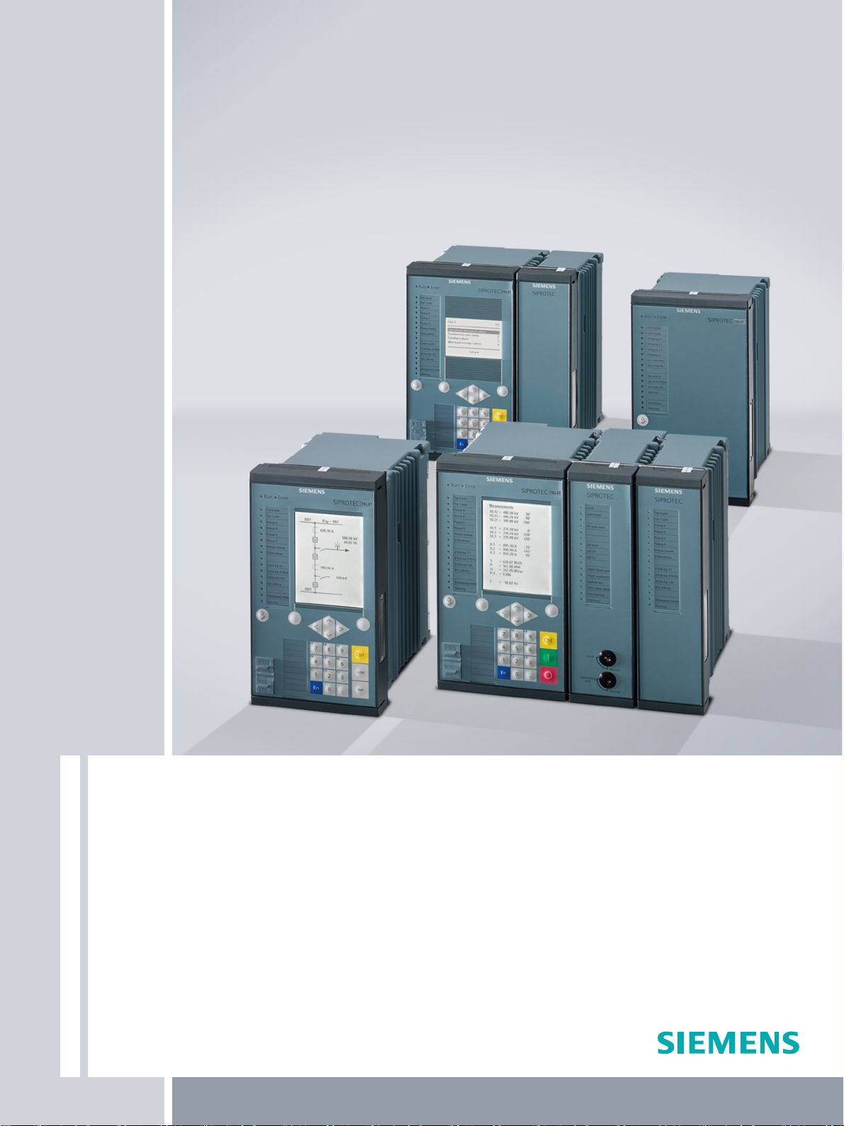
SIPROTEC 5
High-Voltage Bay Controller
6MD85/86
Technical Data
Extract from manual C53000-G5040-C015-A, chapter 11
Energy Automation
V7.80 and higher
Page 2

i
i
NOTE
For your own safety, observe the warnings and safety instructions contained in this document, if available.
Disclaimer of Liability
This document has been subjected to rigorous technical
review before being published. It is revised at regular intervals, and any modifications and amendments are included
in the subsequent issues. The content of this document has
been compiled for information purposes only. Although
Siemens AG has made best efforts to keep the document as
precise and up-to-date as possible, Siemens AG shall not
assume any liability for defects and damage which result
through use of the information contained herein.
This content does not form part of a contract or of business
relations; nor does it change these. All obligations of
Siemens AG are stated in the relevant contractual agreements.
Siemens AG reserves the right to revise this document from
time to time.
Document version: C53000-G5040-C015-A.01
Edition: 05.2018
Version of the product described: V7.80 and higher
Copyright
Copyright © Siemens AG 2018. All rights reserved.
The disclosure, duplication, distribution and editing of this
document, or utilization and communication of the content
are not permitted, unless authorized in writing. All rights,
including rights created by patent grant or registration of a
utility model or a design, are reserved.
Trademarks
SIPROTEC™, DIGSI™, SIGUARD™, SIMEAS™, and SICAM™
are trademarks of Siemens AG. Any unauthorized use is
illegal. All other designations in this document can be
trademarks whose use by third parties for their own
purposes can infringe the rights of the owner.
Page 3
Preface
Purpose of the Manual
This manual describes the functions of SIPROTEC 5 high voltage bay controllers.
Target Audience
Protection system engineers, commissioning engineers, persons entrusted with the setting, testing and maintenance of automation, selective protection and control equipment, and operational crew in electrical installations and power plants.
Scope
This manual applies to the SIPROTEC 5 device family.
Further Documentation
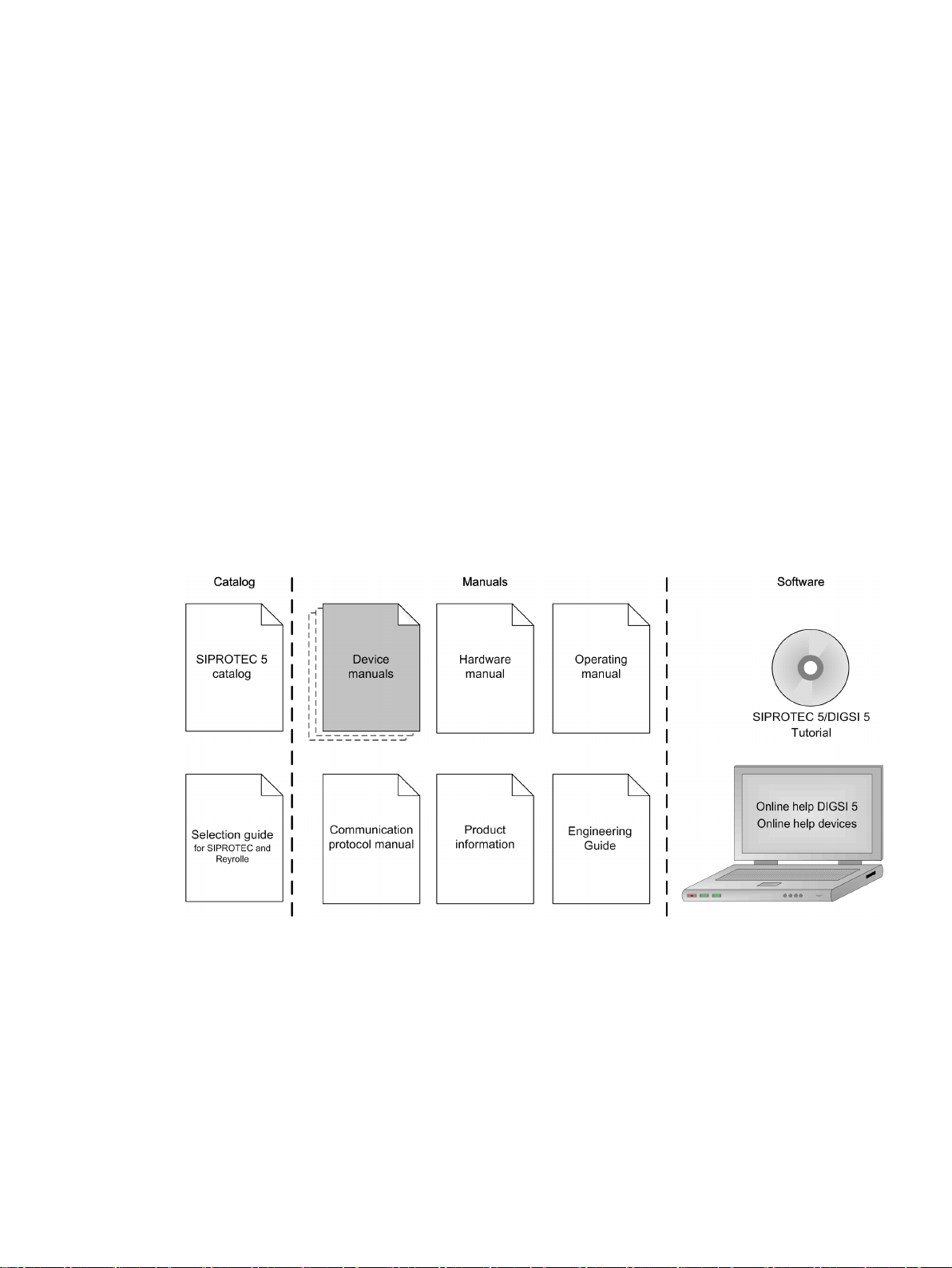
[dwprefdm-221012-01.tif, 3, en_US]
Device manuals
•
Each Device manual describes the functions and applications of a specific SIPROTEC 5 device. The printed
manual and the online help for the device have the same informational structure.
Hardware manual
•
The Hardware manual describes the hardware building blocks and device combinations of the SIPROTEC 5
device family.
Operating manual
•
The Operating manual describes the basic principles and procedures for operating and assembling the
devices of the SIPROTEC 5 range.
SIPROTEC 5, High-Voltage Bay Controller, Manual
C53000-G5040-C015-A, Edition 05.2018
3
Page 4
IND. CONT. EQ.
69CA
Preface
Communication protocol manual
•
The Communication protocol manual contains a description of the protocols for communication within
the SIPROTEC 5 device family and to higher-level network control centers.
Product information
•
The Product information includes general information about device installation, technical data, limiting
values for input and output modules, and conditions when preparing for operation. This document is
provided with each SIPROTEC 5 device.
Engineering Guide
•
The Engineering Guide describes the essential steps when engineering with DIGSI 5. In addition, the Engineering Guide shows you how to load a planned configuration to a SIPROTEC 5 device and update the
functionality of the SIPROTEC 5 device.
DIGSI 5 online help
•
The DIGSI 5 online help contains a help package for DIGSI 5 and CFC.
The help package for DIGSI 5 includes a description of the basic operation of software, the DIGSI princi-
ples and editors. The help package for CFC includes an introduction to CFC programming, basic examples
of working with CFC, and a reference chapter with all the CFC blocks available for the SIPROTEC 5 range.
SIPROTEC 5/DIGSI 5 Tutorial
•
The tutorial on the DVD contains brief information about important product features, more detailed information about the individual technical areas, as well as operating sequences with tasks based on practical
operation and a brief explanation.
SIPROTEC 5 catalog
•
The SIPROTEC 5 catalog describes the system features and the devices of SIPROTEC 5.
Selection guide for SIPROTEC and Reyrolle
•
The selection guide offers an overview of the device series of the Siemens protection devices, and a
device selection table.
Indication of Conformity
Other Standards
IEEE Std C 37.90
The technical data of the product is approved in accordance with UL.
For more information about the UL database, see certified.ul.com
Select Online Certifications Directory and enter E194016 as UL File Number.
This product complies with the directive of the Council of the European Communities
on harmonization of the laws of the Member States relating to electromagnetic
compatibility (EMC Directive 2014/30/EU) and concerning electrical equipment for use
within specified voltage limits (Low Voltage Directive 2014/35/EU).
This conformity has been proved by tests performed according to the Council Directive
in accordance with the product standard EN 60255-26 (for EMC directive) and with the
product standard EN 60255-27 (for Low Voltage Directive) by Siemens AG.
The device is designed and manufactured for application in an industrial environment.
The product conforms with the international standards of IEC 60255 and the German
standard VDE 0435.
[ul_listed_c_us, 1, --_--]
4 SIPROTEC 5, High-Voltage Bay Controller, Manual
C53000-G5040-C015-A, Edition 05.2018
Page 5
Additional Support
!
!
!
For questions about the system, please contact your Siemens sales partner.
Support
Our Customer Support Center provides a 24-hour service.
Training Courses
Inquiries regarding individual training courses should be addressed to our Training Center:
Siemens AG
Siemens Power Academy TD
Humboldtstraße 59
90459 Nürnberg
Germany
Phone: +49 (911) 433-7415
Fax: +49 (911) 433-7929
E-Mail: [email protected]
Internet: www.siemens.com/poweracademy
Preface
Notes on Safety
This document is not a complete index of all safety measures required for operation of the equipment (module
or device). However, it comprises important information that must be followed for personal safety, as well as
to avoid material damage. Information is highlighted and illustrated as follows according to the degree of
danger:
DANGER
DANGER means that death or severe injury will result if the measures specified are not taken.
²
WARNING
WARNING means that death or severe injury may result if the measures specified are not taken.
²
CAUTION
Comply with all instructions, in order to avoid death or severe injuries.
Comply with all instructions, in order to avoid death or severe injuries.
CAUTION means that medium-severe or slight injuries can occur if the specified measures are not taken.
Comply with all instructions, in order to avoid moderate or minor injuries.
²
SIPROTEC 5, High-Voltage Bay Controller, Manual 5
C53000-G5040-C015-A, Edition 05.2018
Page 6

i
i
Preface
NOTICE
NOTICE means that property damage can result if the measures specified are not taken.
Comply with all instructions, in order to avoid property damage.
²
NOTE
Important information about the product, product handling or a certain section of the documentation
which must be given particular attention.
Qualified Electrical Engineering Personnel
Only qualified electrical engineering personnel may commission and operate the equipment (module, device)
described in this document. Qualified electrical engineering personnel in the sense of this manual are people
who can demonstrate technical qualifications as electrical technicians. These persons may commission,
isolate, ground and label devices, systems and circuits according to the standards of safety engineering.
Proper Use
The equipment (device, module) may be used only for such applications as set out in the catalogs and the
technical description, and only in combination with third-party equipment recommended and approved by
Siemens.
Problem-free and safe operation of the product depends on the following:
Proper transport
•
Proper storage, setup and installation
•
Proper operation and maintenance
•
When electrical equipment is operated, hazardous voltages are inevitably present in certain parts. If proper
action is not taken, death, severe injury or property damage can result:
The equipment must be grounded at the grounding terminal before any connections are made.
•
All circuit components connected to the power supply may be subject to dangerous voltage.
•
Hazardous voltages may be present in equipment even after the supply voltage has been disconnected
•
(capacitors can still be charged).
Operation of equipment with exposed current-transformer circuits is prohibited. Before disconnecting the
•
equipment, ensure that the current-transformer circuits are short-circuited.
The limiting values stated in the document must not be exceeded. This must also be considered during
•
testing and commissioning.
6 SIPROTEC 5, High-Voltage Bay Controller, Manual
C53000-G5040-C015-A, Edition 05.2018
Page 7

Open Source Software
i
i
The product contains, among other things, Open Source Software developed by third parties. The Open
Source Software used in the product and the license agreements concerning this software can be found in the
Readme_OSS. These Open Source Software files are protected by copyright. Your compliance with those
license conditions will entitle you to use the Open Source Software as foreseen in the relevant license. In the
event of conflicts between Siemens license conditions and the Open Source Software license conditions, the
Open Source Software conditions shall prevail with respect to the Open Source Software portions of the software. The Open Source Software is licensed royalty-free. Insofar as the applicable Open Source Software
License Conditions provide for it you can order the source code of the Open Source Software from your
Siemens sales contact - against payment of the shipping and handling charges - for a period of at least 3 years
since purchase of the Product. We are liable for the Product including the Open Source Software contained in
it pursuant to the license conditions applicable to the Product. Any liability for the Open Source Software
beyond the program flow intended for the Product is explicitly excluded. Furthermore any liability for defects
resulting from modifications to the Open Source Software by you or third parties is excluded. We do not
provide any technical support for the Product if it has been modified.
When using DIGSI 5 in online mode, you are provided with the option to go to the main menu Show open
source software information and read and display the Readme_OSS file containing the original license text
and copyright information.
To do this, the following steps are necessary:
Switch to online mode.
•
Select the device.
•
Select Online in the menu bar.
•
Click Show open source software information.
•
NOTE
To read the Readme_OSS file, a PDF viewer must be installed on the computer.
In order to operate SIPROTEC 5 devices, a valid DIGSI 5 license is required.
SIPROTEC 5, High-Voltage Bay Controller, Manual
C53000-G5040-C015-A, Edition 05.2018
7
Page 8

11
Technical Data
11.1 General Device Data 1105
11.2 Protection Interface and Protection Topology 1114
11.3 Date and Time Synchronization 1116
11.4 Automatic Reclosing 1117
11.5 Phasor Measurement Unit 1118
11.6 Circuit-Breaker Wear Monitoring 1119
11.7 External Trip Initiation 1120
11.8 Overcurrent Protection, Phases 1121
11.9 Overcurrent Protection, Ground 1133
11.10 Directional Overcurrent Protection, Phases 1143
11.11 Directional Overcurrent Protection, Ground 1149
11.12 Inrush-Current Detection 1159
11.13 Instantaneous High-Current Tripping 1160
11.14 Stage with Definite-Time Characteristic Curve 1161
11.15 Stage with Inverse-Time Characteristic Curve 1163
11.16 Voltage-Dependent Overcurrent Protection, Phases 1165
11.17 Overvoltage Protection with 3-Phase Voltage 1168
11.18 Overvoltage Protection with Positive-Sequence Voltage 1170
11.19 Overvoltage Protection with Any Voltage 1171
11.20 Undervoltage Protection with 3-Phase Voltage 1173
11.21 Undervoltage Protection with Any Voltage 1176
11.22 Overfrequency Protection 1177
11.23 Underfrequency Protection 1178
11.24 Underfrequency Load Shedding 1179
11.25 Rate of Frequency Change Protection 1181
11.26 Power Protection (P,Q), 3-Phase 1183
11.27 Instantaneous Tripping at Switch onto Fault 1184
11.28 Circuit-Breaker Failure Protection 1185
11.29 Negative-Sequence Protection with Definite-Time Characteristic Curve 1187
11.30 Stage with Inverse-Time Characteristic Curve 1188
11.31 Thermal Overload Protection, 3-Phase – Advanced 1190
11.32 Thermal Overload Protection, 1-Phase 1194
11.33 Temperature Supervision 1197
11.34 Analog-Units Function Group 1198
SIPROTEC 5, High-Voltage Bay Controller, Manual 1103
C53000-G5040-C015-A, Edition 05.2018
Page 9

Technical Data
11.35 Synchronization Function 1199
11.36 Arc Protection 1201
11.37 Voltage Controller 1202
11.38 Current-Balance Supervision 1206
11.39 Voltage-Balance Supervision 1207
11.40 Current-Sum Supervision 1208
11.41 Voltage-Sum Supervision 1209
11.42 Current Phase-Rotation Supervision 1210
11.43 Voltage Phase-Rotation Supervision 1211
11.44 Trip-Circuit Supervision 1212
11.45 Analog Channel Supervision via Fast Current Sum 1213
11.46 Measuring-Voltage Failure Detection 1214
11.47 Operational Measured Values and Statistical Values 1216
11.48 Energy Values 1220
11.49 CFC 1221
1104 SIPROTEC 5, High-Voltage Bay Controller, Manual
C53000-G5040-C015-A, Edition 05.2018
Page 10
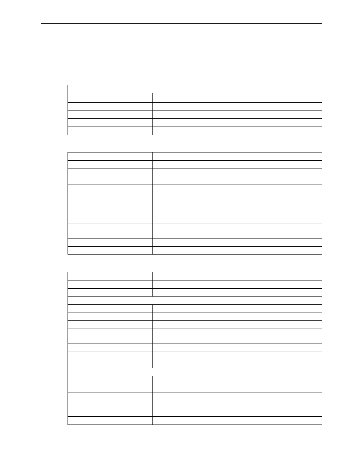
Technical Data
11.1 General Device Data
11.1
11.1.1
Voltage Input
Measuring-Transducer Inputs (via Module ANAI-CA-4EL)
General Device Data
Analog Inputs
All current, voltage, and power data are specified as RMS values.
Rated frequency f
Input and output modules IO202, IO208, IO211, IO214 IO215
Measuring range 0 V to 200 V 0 V to 7.07 V
Input impedance < 0.1 VA < 0.01 VA
Thermal rating 230 V continuously 20 V continuously
Insulation class SELV (Safety Extra Low Voltage) (according to IEC 60255-27)
Connector type 8-pin multiple contact strip
Differential current input channels 4
Measuring range DC -24 mA to +24 mA
Fault < 0.5 % of the measuring range
Input impedance 140 Ω
Conversion principle Delta-sigma (16 bit)
Permissible potential difference
between channels
Galvanic separation from ground/
housing
Permissible overload DC 100 mA continuously
Measurement repetition 200 ms
rated
50 Hz, 60 Hz
DC 20 V
DC 700 V
Measuring-Transducer Inputs (via Module ARC-CD-3FO)
Connector type
Number of transceivers 3
Fiber type Polymer Optical Fiber (POF) 1 mm
Receiver
Maximum -10 dBm ± 2 dBm
Minimum -40 dBm ± 2 dBm
Spectrum 400 nm to 1100 nm
Attenuation In the case of plastic optical fibers, you can expect a path attenuation of
Optical budget
Analog sampling rate 16 kHz
ADC type 10-bit successive approximation
Transmitter
Type LED
Wavelength λ = 650 nm
Transmit power Minimum 0 dBm
Numerical aperture
Signal rate connection test 1 pulse per second
1
AVAGO AFBR-4526Z
0.2 dB/m Additional attenuation comes from the plug and sensor head.
Minimal 25 dB
Maximum 2 dBm
2
0.5
SIPROTEC 5, High-Voltage Bay Controller, Manual 1105
C53000-G5040-C015-A, Edition 05.2018
Page 11
i
i
Technical Data
11.1 General Device Data
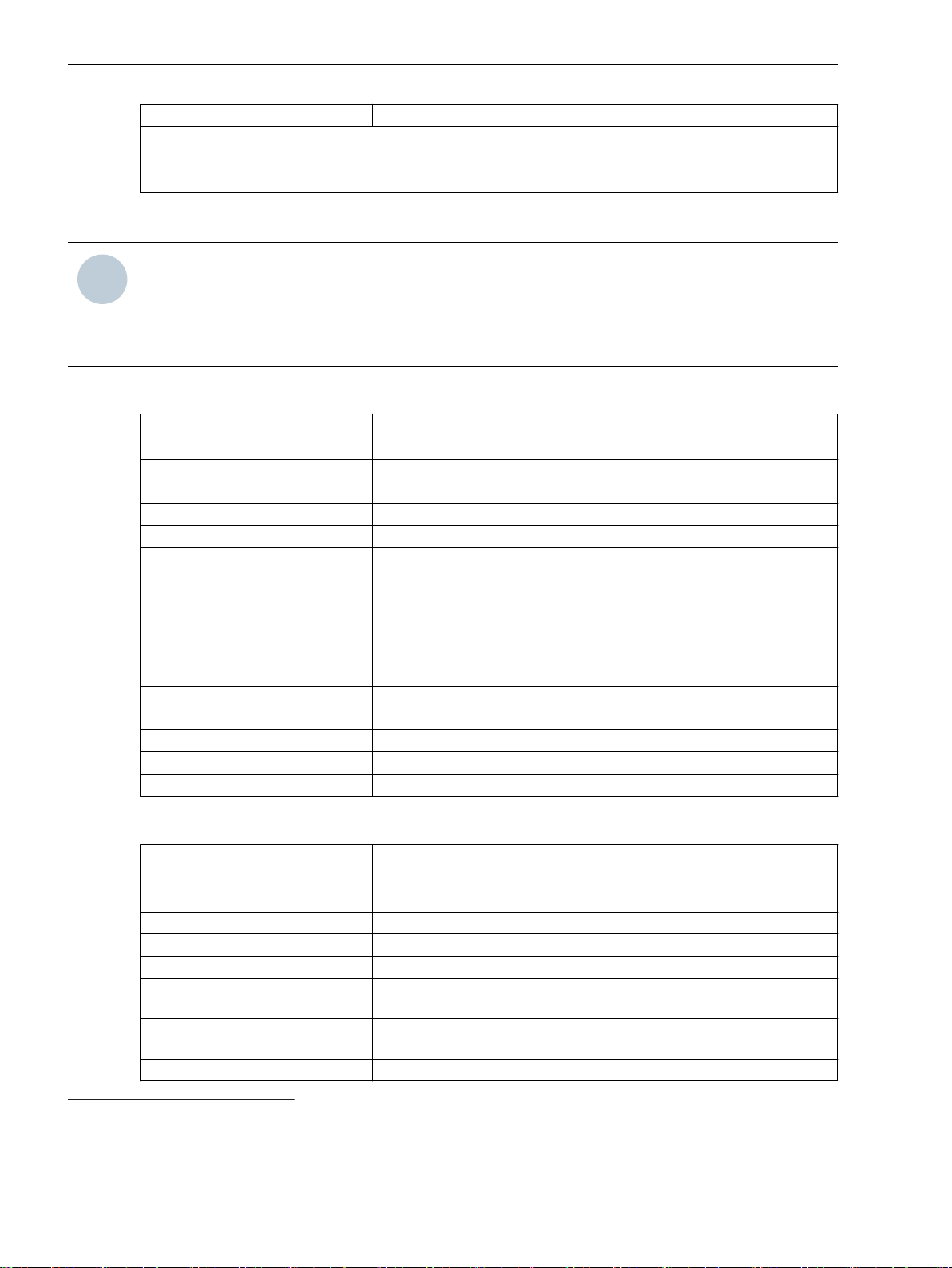
Pulse duration connection test 11 μs
Comment:
1
All values in combination with sensors approved by Siemens.
2
Numerical aperture (NA = sin θ (launch angle))
High-Speed Measuring-Transducer Inputs, Voltage/Current (via IO210, IO212)
NOTE
Current and voltage must not be connected at the same time to one measuring-transducer input. Instead,
only connect either current or voltage. For EMC reasons, do not connect a line to an unused input (current
or voltage).
Use shielded cables.
Table 11-1 High-Speed Measuring-Transducer Inputs, Voltage
Differential voltage input channels
Measuring range DC -10 V to +10 V
Fault < 0.5 % of the measuring range
Input impedance 48 kΩ
Conversion principle Delta-sigma (16 bit)
Insulation test voltage between the
channels
Insulation test voltage with respect
to ground/housing
Max. permissible voltage with
respect to ground on the measuring inputs
Permissible overload DC 20 V continuously
Measured-value repetition 62.5 μs
Insulation class IO210 ELV (Extra Low Voltage) (acc. to IEC 60255-27)
Insulation class IO212 SELV (acc. to IEC 60255-27)
IO210: 4
IO212: 8
DC 3.5 kV
DC 3.5 kV
300 V
DC 60 V continuously (IO210 MT3 terminal point C9)
27
28
Table 11-2 High-Speed Measuring-Transducer Inputs, Current
Differential current input channels
Measuring range DC -20 mA to +20 mA
Fault < 0.5 % of the measuring range
Input impedance, current 12 Ω
Conversion principle Delta-sigma (16 bit)
Permissible potential difference
between channels
Galvanic separation with respect to
ground/housing
Permissible current overload DC 100 mA continuously
27
The IO210 has 4 high-speed measuring-transducer inputs. They can be used either as a voltage or current input.
28
The IO212 has 8 high-speed measuring-transducer inputs. They can be used either as a voltage or current input.
29
The IO210 has 4 high-speed measuring-transducer inputs. They can be used either as a voltage or current input.
30
The IO212 has 8 high-speed measuring-transducer inputs. They can be used either as a voltage or current input.
1106 SIPROTEC 5, High-Voltage Bay Controller, Manual
IO210: 4
IO212: 8
DC 3.5 kV
DC 3.5 kV
29
30
C53000-G5040-C015-A, Edition 05.2018
Page 12
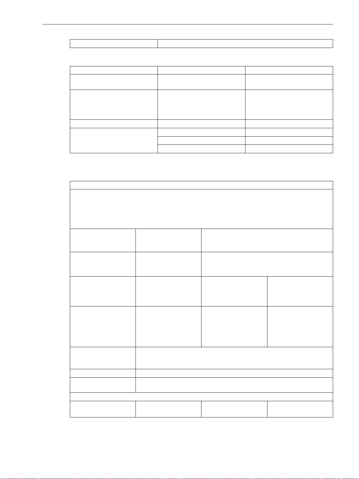
Measured-value repetition 62.5 μs
Temperature Inputs
Settings Value Note
Insulation class PELV (Protective Extra Low Voltage)
Measurement mode
Connector type 16-pin, 17-pin terminal spring –
Temperature measuring range -65 °C to +710 °C For PT100
–
(acc. to IEC 60255-27)
Pt 100 Ω
•
Ni 100 Ω
•
Ni 120 Ω
•
3-wire connection, shielded cables
-50 °C to +250 °C For NI100
-50 °C to +250 °C For NI120
–
Technical Data
11.1 General Device Data
11.1.2
Supply Voltage
Integrated Power Supply
For modular devices, the following printed circuit-board assemblies have a power supply:
PS201 – Power supply of the base module and of the 1st device row
PS203 – Power supply of the 2nd device row
CB202 – Plug-in module assembly with integrated power supply, for example, to accommodate communica-
tion modules
Permissible voltage
ranges
(PS201, PS203, CB202)
Auxiliary rated voltage V
(PS201, PS203, CB202)
Permissible voltage
ranges (PS101)
Only for non-modular
devices
Auxiliary rated voltage V
(PS101)
Only for non-modular
devices
Superimposed alternating
voltage, peak-to-peak,
IEC 60255-11
Inrush current ≤ 18 A
Recommended external
protection
Internal fuse
– DC 24 V to DC 48 V DC 60 V to DC 125 V DC 24 V to DC 48 V
DC 19 V to DC 60 V DC 48 V to DC 300 V
AC 80 V to AC 265 V, 50 Hz/60 Hz
DC 24 V/DC 48 V DC 60 V/DC 110 V/DC 125 V/DC 220 V/
H
DC 250 V or
AC 100 V/AC 115 V/AC 230 V, 50 Hz/60 Hz
DC 19 V to DC 60 V DC 48 V to 150 V DC 88 V to DC 300 V
AC 80 V to AC 265 V,
50 Hz/60 Hz
DC 24 V/DC 48 V DC 60 V/DC 110 V/
H
DC 125 V
≤ 15 % of the DC auxiliary rated voltage (applies only to direct voltage)
Miniature circuit breaker 6 A, characteristic C according to IEC 60898
DC 110 V/ DC 125 V/
DC 220 V/DC 250 V
or
AC 100 V/AC 115 V/
AC 230 V, 50 Hz/60 Hz
AC 100 V to AC 230 V
SIPROTEC 5, High-Voltage Bay Controller, Manual 1107
C53000-G5040-C015-A, Edition 05.2018
Page 13
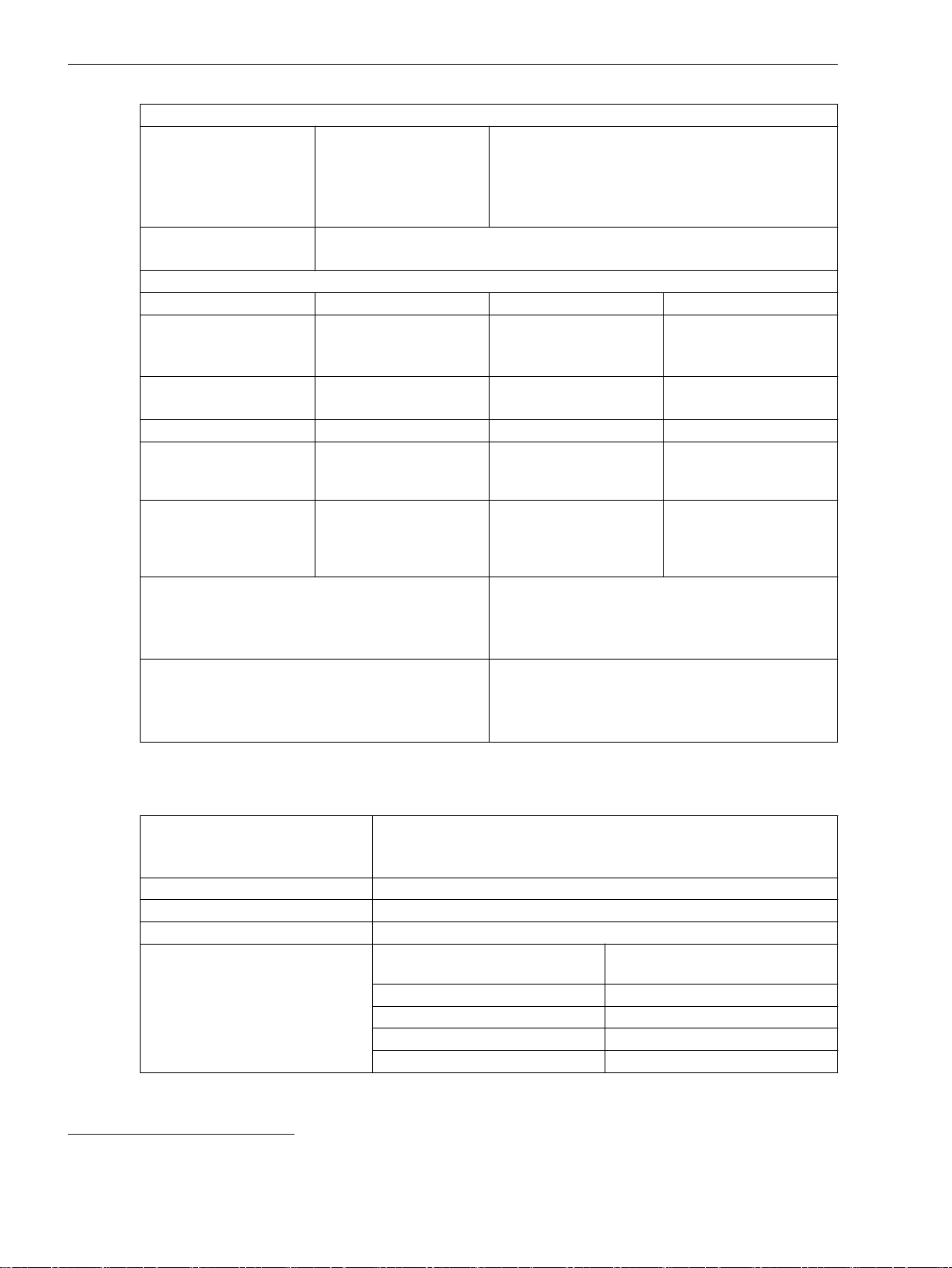
Technical Data
11.1 General Device Data
Integrated Power Supply
PS101
Only for non-modular
devices
PS201, PS203, CB202 2 A time-lag, AC 250 V, DC 300 V, UL recognized
Power consumption (life relay active)
– DC AC 230 V/50 Hz AC 115 V/50 Hz
1/3 base module, non-
modular
Without plug-in modules
1/3 base module, modular
Without plug-in modules
1/6 expansion module 3 W 6 VA 6 VA
1/6 plug-in module
assembly without plug-in
modules (modules CB202)
Plug-in module for base
module or plug-in module
assembly (for example,
communication module)
Stored-energy time for auxiliary voltage outage or
short circuit, modular devices
IEC 61000-4-11
IEC 61000-4-29
Stored-energy time for auxiliary voltage outage or
short circuit, non-modular devices
IEC 61000-4-11
IEC 61000-4-29
4 A inert, AC 250 V,
DC 150 V,
2 A time-lag, AC 250 V, DC 300 V, UL recognized
SIBA type 179200 or Schurter type SPT 5x20
UL recognized
SIBA type 179200 or
Schurter type SPT 5x20
SIBA type 179200 or Schurter type SPT 5x20
7.0 W 16 VA 12.5 VA
13 W 33 VA 24 VA
3.5 W 14 VA 7 VA
< 5 W < 6 VA < 6 VA
For V ≥ DC 24 V ≥ 50 ms
For V ≥ DC 110 V ≥ 50 ms
For V ≥ AC 115 V ≥ 50 ms
For V ≥ DC 24 V ≥ 20 ms
For V ≥ DC 60 V/DC 110 V ≥ 50 ms
For V ≥ AC 115 V ≥ 200 ms
11.1.3
Binary Inputs
Rated voltage range
DC 24 V to 250 V
The binary inputs of SIPROTEC 5 are bipolar with the exception of the
binary inputs on the IO230, the IO231, and the IO233.
Current consumption, excited Approx. DC 0.6 mA to 2.5 mA (independent of the control voltage)
Power consumption, max. 0.6 VA
Pickup time Approx. 3 ms
Dropout time
31
Capacitive load (supply-line capaci-
Dropout time
tance)
< 5 nF < 4 ms
< 10 nF < 6 ms
< 50 nF < 10 ms
< 220 nF < 35 ms
31
For time-critical applications with low-active signals, consider the specified dropout times. If necessary, provide for active discharge of
the binary input (for example, a resistor in parallel to the binary input or using a change-over contact).
1108 SIPROTEC 5, High-Voltage Bay Controller, Manual
C53000-G5040-C015-A, Edition 05.2018
Page 14
Technical Data
11.1 General Device Data
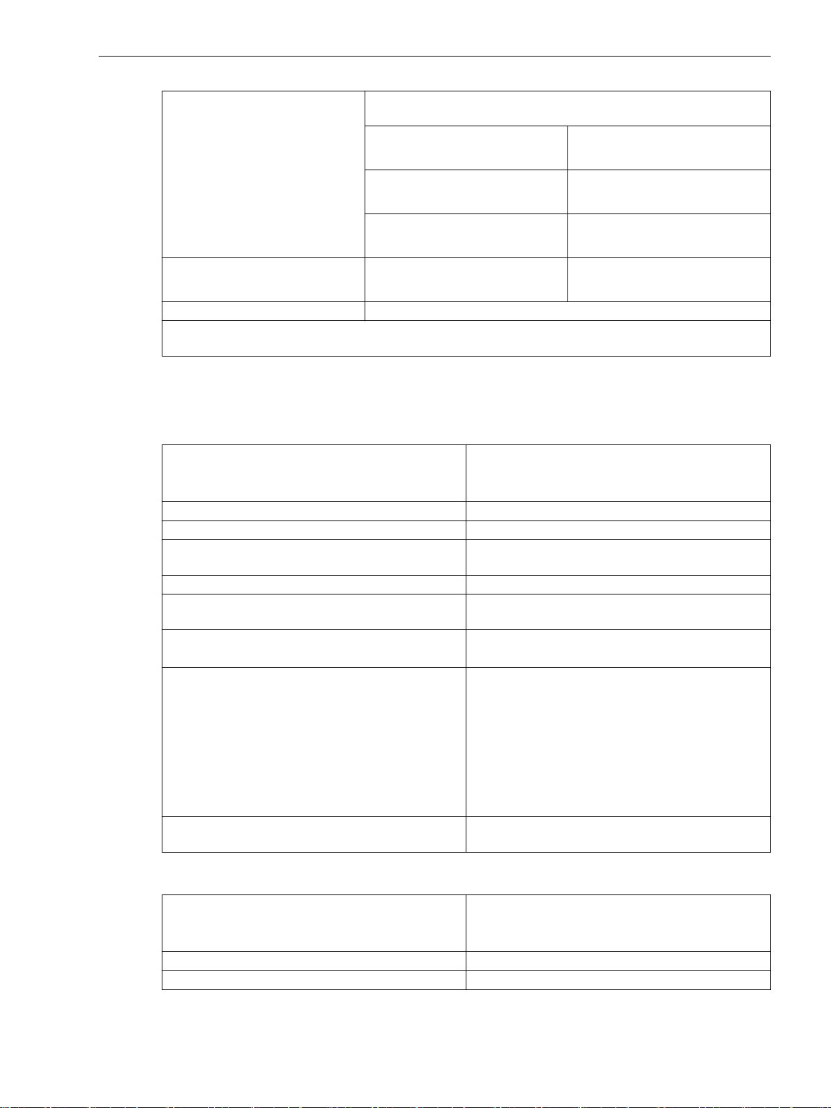
Control voltage for all modules
with binary inputs except the
IO233
Control voltage for binary inputs of
the IO233 modules
Maximum permitted voltage DC 300 V
The binary inputs contain interference suppression capacitors. To ensure EMC immunity, use the terminals
shown in the terminal diagrams/connection diagrams to connect the binary inputs to the common potential.
11.1.4
Relay Outputs
Standard Relay (Type S)
Switching capacity On: 1000 W/VA
AC and DC contact voltage 250 V
Permissible current per contact (continuous) 5 A
Permissible current per contact (switching on and
holding)
Short-time current across closed contact 250 A for 30 ms
Total permissible current for contacts connected to
common potential
Switching time OOT (Output Operating Time)
Additional delay of the output medium used
Max. rated data of the output contacts in accordance
with UL certification
Interference suppression capacitors across the
contacts
Adapt the binary-input threshold to be set in the device to the control
voltage.
Range 1 for 24 V, 48 V, and 60 V
Control voltage
Range 2 for 110 V and 125 V
Control voltage
Range 3 for 220 V and 250 V
Control voltage
Range V
V
≤ DC 10 V
low
V
≥ DC 19 V
high
V
≤ DC 44 V
low
V
≥ DC 88 V
high
V
≤ DC 88 V
low
V
≥ DC 176 V
high
≤ DC 85 V
low
V
≥ DC 105 V
high
Off: 30 VA; 40 W ohmic;
30 W/VA at L/R ≤ 40 ms
30 A for 1 s (make contact)
5 A
Make time: typical: 8 ms; maximum: 10 ms
Break time: typical: 2 ms; maximum: 5 ms
DC 24 V, 5 A, General Purpose
DC 48 V, 0.8 A, General Purpose
DC 240 V, 0.1 A, General Purpose
AC 240 V, 5 A, General Purpose
AC 120 V, 1/6 hp
AC 250 V, 1/2 hp
B300
R300
4.7 nF, ± 20 %, AC 250 V
Fast Relay (Type F)
Switching capacity
On: 1000 W/VA
Off: 30 VA; 40 W ohmic;
30 W/VA at L/R ≤ 40 ms
AC and DC contact voltage 250 V
Permissible current per contact (continuous) 5 A
SIPROTEC 5, High-Voltage Bay Controller, Manual 1109
C53000-G5040-C015-A, Edition 05.2018
Page 15
Technical Data
11.1 General Device Data
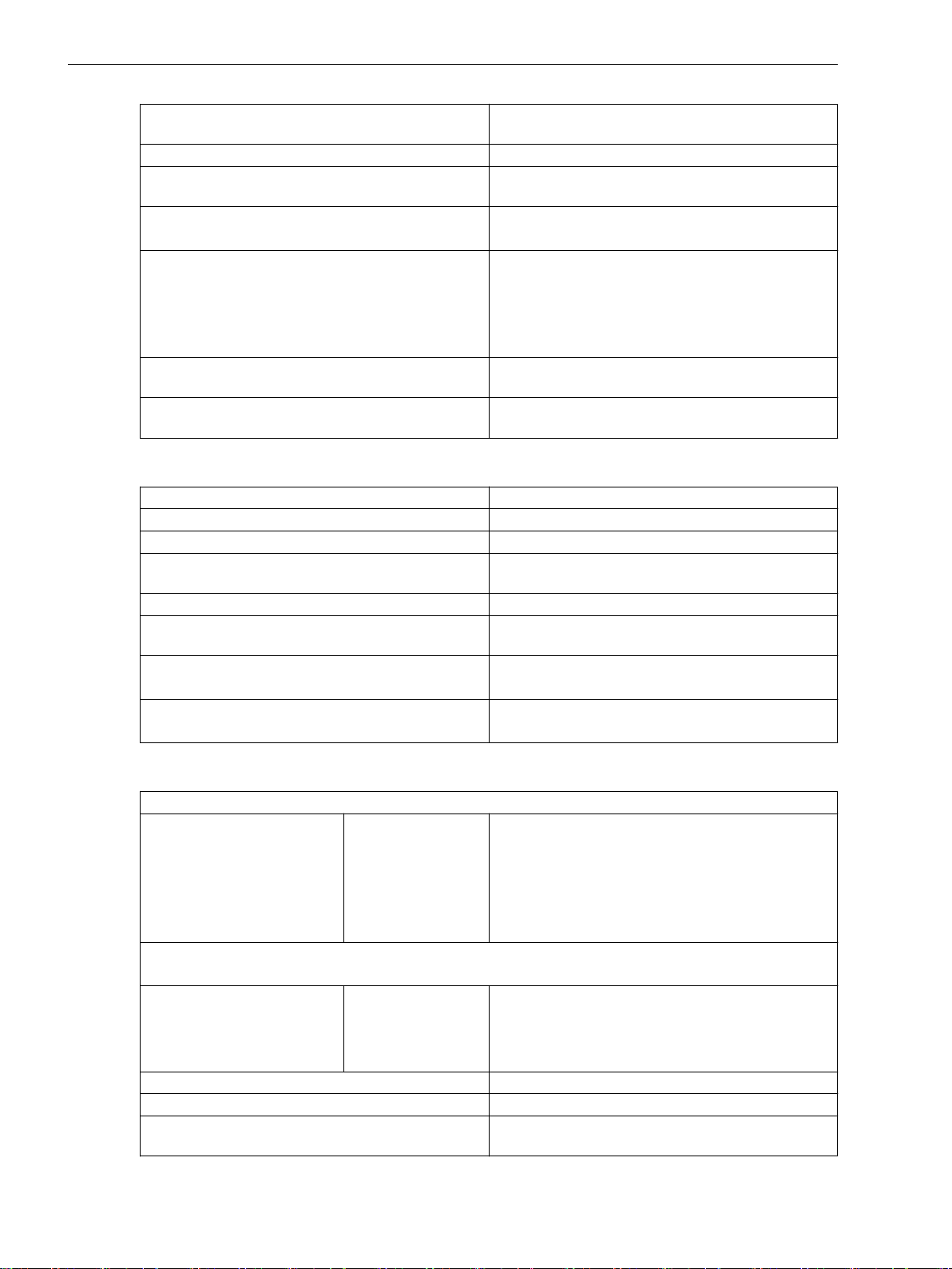
Permissible current per contact (switching on and
holding)
Short-time current across closed contact 250 A for 30 ms
Total permissible current for contacts connected to
common potential
Switching time OOT (Output Operating Time)
Additional delay of the output medium used
Rated data of the output contacts in accordance with
UL certification
Interference suppression capacitors across the
contacts
Supervision 2-channel activation with cyclic testing (only for make
High-Speed Relay with Semiconductor Acceleration (Type HS)
Switching capacity On/Off: 1000 W/VA
Contact voltage AC 200 V, DC 250 V
Permissible current per contact (continuous) 5 A
Permissible current per contact (switching on and
holding)
Short-time current across closed contact 250 A for 30 ms
Total permissible current for contacts connected to
common potential
Switching time OOT (Output Operating Time)
Additional delay of the output medium used
Rated data of the output contacts in accordance with
UL certification
30 A for 1 s (make contact)
5 A
Make time: typical: 4 ms; maximum: 5 ms
Break time: typical: 2 ms; maximum: 5 ms
AC 120 V, 5 A, General Purpose
AC 250 V, 5 A, General Purpose
AC 250 V, 0.5 hp
B300
R300
4.7 nF, ± 20 %, AC 250 V
contact)
30 A for 1 s (make contact)
5 A
Make time, typical: 0.2 ms; maximum: 0.2 ms
Break time, typical: 9 ms; maximum: 9 ms
B150
Q300
Power Relay (for Direct Control of Motor Switches)
Switching capacity for permanent and periodic operation
250 V/4.0 A
220 V/4.5 A
110 V/5.0 A
60 V/5.0 A
48 V/5.0 A
24 V/5.0 A
1000 W
1000 W
550 W
300 W
240 W
120 W
In order to prevent any damage, the external protection circuit must switch off the motor in case the rotor
is blocked.
Turn on switching power for 30 s, recovery time until switching on again is 15 minutes.
For short-term switching operations, an impulse/pause ratio of 3 % must be considered.
100 V/9.0 A
60 V/10.0 A
48 V/10.0 A
24 V/10.0 A
1000 W
600 W
480 W
240 W
Continuous and inching operation is not permitted.
In order to prevent any damage, the external protec-
tion circuit must switch off the motor in case the rotor
is blocked.
AC and DC contact voltage 250 V
Permissible continuous current per contact 5 A
Permissible current per contact (switching on and
30 A for 1 s
holding)
1110 SIPROTEC 5, High-Voltage Bay Controller, Manual
C53000-G5040-C015-A, Edition 05.2018
Page 16
Technical Data
11.1 General Device Data
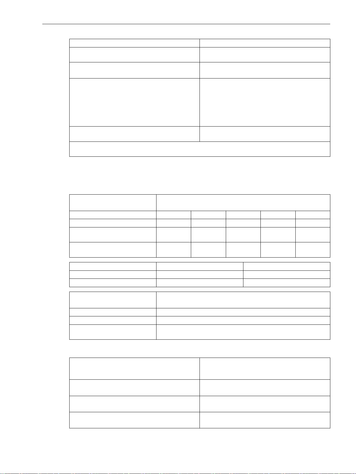
Short-time current across closed contact 250 A for 30 ms
Total permissible current for contacts connected to
common potential
Switching time OOT (Output Operating Time)
Additional delay of the output medium used
Rated data of the output contacts in accordance with
UL certification
Interference suppression capacitors across the
contacts
The power relays operate in interlocked mode, that is, only one relay of each switching pair picks up at a time
thereby avoiding a power-supply short circuit.
5 A
≤ 16 ms
DC 300 V, 4.5 A - 30 s ON, 15 min OFF
DC 250 V, 1 hp motor - 30 s ON, 15 min OFF
DC 110 V, 3/4 hp motor - 30 s ON, 15 min OFF
DC 60 V, 10 A, 1/2 hp motor - 30 s ON, 15 min OFF
DC 48 V, 10 A, 1/3 hp motor - 30 s ON, 15 min OFF
DC 24 V, 10 A, 1/6 hp motor - 30 s ON, 15 min OFF
4.7 nF, ± 20 %, AC 250 V
11.1.5
Masses
Design Data
Device Size
Weight of the Modular Devices
Type of construction 1/3 1/2 2/3 5/6 1/1
Flush-mounting device 4.4 kg 7.2 kg 9.9 kg 12.7 kg 15.5 kg
Surface-mounted device with inte-
grated on-site operation panel
Surface-mounted device with
detached on-site operation panel
Detached on-site operation panel 1/3 1.9 kg
Detached on-site operation panel 1/6 1.1 kg
Type of construction 1/3
Flush-mounting device 3.6 kg
Bracket for non-modular surface-
mounted variant
7.4 kg 11.7 kg 15.9 kg 20.2 kg 24.5 kg
4.7 kg 7.8 kg 10.8 kg 13.9 kg 17.0 kg
Size Weight
Device Size
Weight of the Non-Modular Devices 7xx82
1.9 kg
Dimensions of the Base and 1/3 Modules
Type of Construction (Maximum Dimensions)
Flush-mounting device 150 mm x 266 mm x 229 mm
Surface-mounted device with integrated on-site operation panel
Surface-mounted device with detached on-site operation panel
SIPROTEC 5, High-Voltage Bay Controller, Manual 1111
C53000-G5040-C015-A, Edition 05.2018
Width over all x Height over all x Depth (incl.
Current Terminal), Width and Depth Each Rounded
up to the Next Full mm (in Inches)
(5.91 x 10.47 x 9.02)
150 mm x 314 mm x 337 mm
(5.91 x 12.36 x 13.27)
150 mm x 314 mm x 230 mm
(5.91 x 12.36 x 9.06)
Page 17
Technical Data
11.1 General Device Data
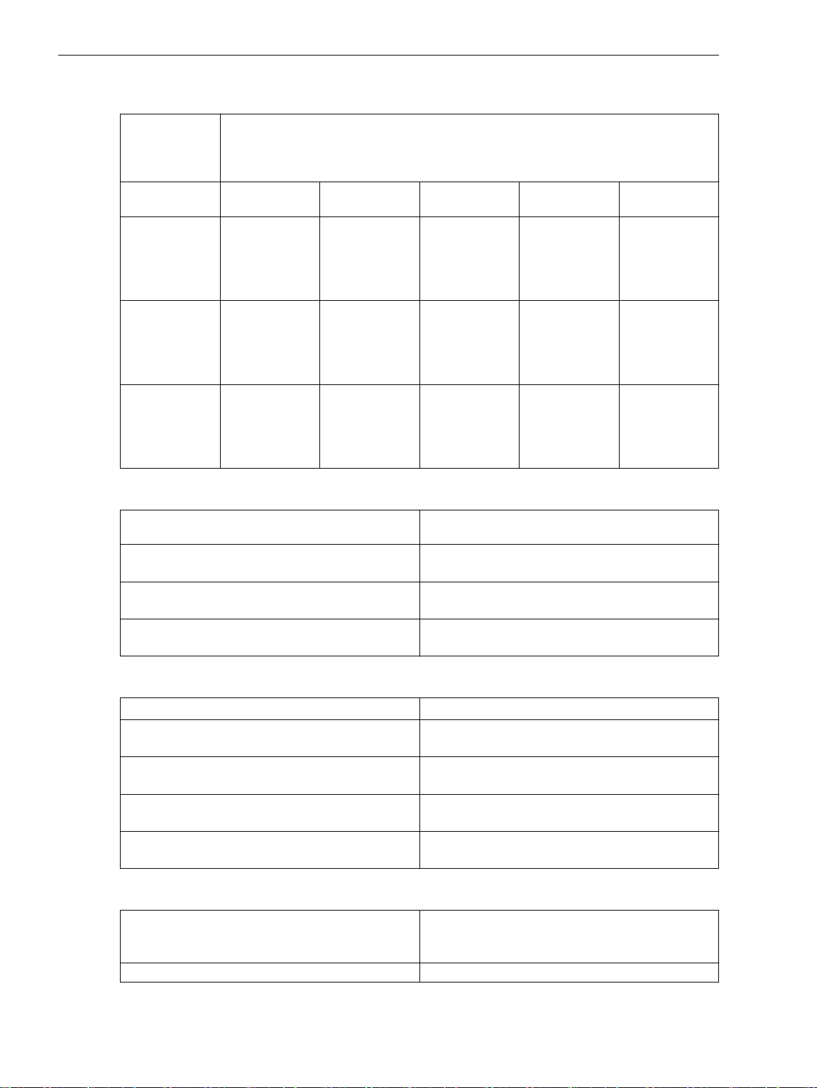
Dimensions of Device Rows
Type of
Construction
Width over all x Height over all x Depth (incl. Current Terminal), Width and Depth
Each Rounded up to the Next Full mm (in Inches)
(Maximum
Dimensions)
Type of construc-
1/3 1/2 2/3 5/6 1/1
tion
Flush-mounting
device
150 mm x
266 mm x
229 mm
(5.91 x 10.47 x
9.02)
Surfacemounted device
with integrated
on-site operation
panel
Surfacemounted device
with detached
on-site operation
panel
150 mm x
314 mm x
337 mm
(5.91 x 12.36 x
13.27)
150 mm x
314 mm x
230 mm
(5.91 x 12.36 x
9.06)
Expansion Module Dimensions
Type of Construction (Maximum Dimensions)
Flush-mounting device 75 mm x 266 mm x 229 mm
Surface-mounted device with integrated on-site operation panel
Surface-mounted device with detached on-site operation panel
225 mm x
266 mm x
229 mm
(8.86 x 10.47 x
9.02)
225 mm x
314 mm x
337 mm
(8.86 x 12.36 x
13.27)
225 mm x
314 mm x
230 mm
(8.86 x 12.36 x
9.06)
300 mm x
266 mm x
229 mm
(11.81 x 10.47 x
9.02)
300 mm x
314 mm x
337 mm
(11.81 x 12.36 x
13.27)
300 mm x
314 mm x
230 mm
(11.81 x 12.36 x
9.06)
375 mm x
266 mm x
229 mm
(14.76 x 10.47 x
9.02)
375 mm x
314 mm x
337 mm
(14.76 x 12.36 x
13.27)
375 mm x
314 mm x
230 mm
(14.76 x 12.36 x
9.06)
450 mm x
266 mm x
229 mm
(17.72 x 10.47 x
9.02)
450 mm x
314 mm x
337 mm
(17.72 x 12.36 x
13.27)
450 mm x
314 mm x
230 mm
(17.72 x 12.36 x
9.06)
Width x Height x Depth, Width and Depth Each
Rounded up to the Next Full mm (in Inches)
(2.95 x 10.47 x 9.02)
75 mm x 314 mm x 337 mm
(2.95 x 12.36 x 13.27)
75 mm x 314 mm x 230 mm
(2.95 x 12.36 x 9.06)
Plug-In Module Dimensions
Type of Construction (Maximum Dimensions)
Width x Height x Depth (in Inches)
USART-Ax-xEL, ETH-Bx-xEL 61 mm x 45 mm x 120.5 mm
(2.4 x 1.77 x 4.74)
USART-Ax-xFO, ETH-Bx-xFO (without protection
cover)
61 mm x 45 mm x 132.5 mm
(2.4 x 1.77 x 5.22)
ANAI-CA-4EL 61 mm x 45 mm x 119.5 mm
(2.4 x 1.77 x 4.7)
ARC-CD-3FO 61 mm x 45 mm x 120.5 mm
(2.4 x 1.77 x 4.74)
Minimum Bending Radii of the Connecting Cables Between the On-Site Operation Panel and the Base Module
Fiber-optic cable
R = 50 mm
Pay attention to the length of the cable protection
sleeve, which you must also include in calculations.
D-Sub cable R = 50 mm (minimum bending radius)
1112 SIPROTEC 5, High-Voltage Bay Controller, Manual
C53000-G5040-C015-A, Edition 05.2018
Page 18
Degree of Protection According to IEC 60529
i
i
i
i
Technical Data
11.1 General Device Data
For equipment in the surface-mounting housing
For equipment in the flush-mounting housing
For operator protection (back side) IP2x for current terminal (installed)
Degree of pollution, IEC 60255-27 2
Maximum altitude above sea level 2000 m (6561.68 ft)
UL Note
Type 1 if mounted into a door or front cover of an enclosure.
When expanding the device with the 2nd device row, then they must be mounted completely inside an
enclosure.
Tightening Torques for Terminal Screws
Type of Line Current Terminal Voltage Terminal with
Stranded wires with ringtype lug
Stranded wires with bootlace ferrules or pin-type
lugs
Solid conductor, bare
(2 mm2)
2.7 Nm No ring-type lug No ring-type lug
2.7 Nm 1.0 Nm 0.6 Nm
2.0 Nm 1.0 Nm –
IP5432 for front
IP5432 for front
IP2x for voltage terminal (installed)
Voltage Terminal with
Spring-Loaded Terminals
Screw Connection
NOTE
For current and voltage terminals, the maximum speed of the tool must not exceed 640 rpm.
NOTE
Use copper cables only.
Torques for Other Screw Types
Screw Type
M4 x 20 1.2 Nm
M4 x 8 1.2 Nm
M2.5 x 6 0.39 Nm
Countersunk screw, M2.5 x 6 0.39 Nm
Countersunk screw, M2.5 x 8 0.39 Nm
Collar screw, M4 x 20 0.7 Nm
Torque
32
The provided plug-in label must be used for expansion modules with LEDs.
SIPROTEC 5, High-Voltage Bay Controller, Manual 1113
C53000-G5040-C015-A, Edition 05.2018
Page 19
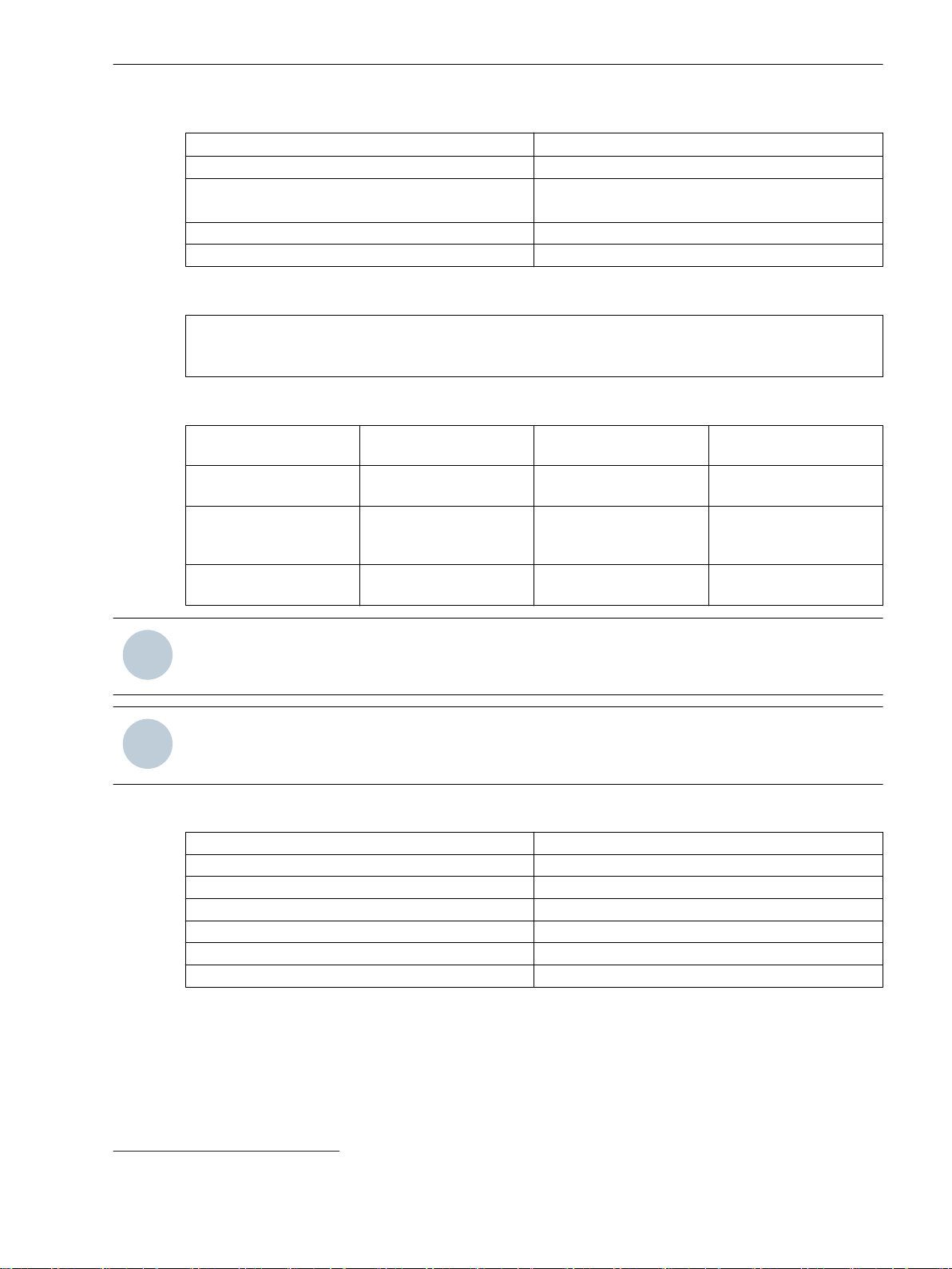
Technical Data
11.2 Protection Interface and Protection Topology
11.2
Setting Values
Transmission Rate
Protection Interface and Protection Topology
Mode On
PPS Synchronization Telegr. and PPS
Blocking of the unbalanced
runtimes
Maximum signal runtime threshold 0.1 ms to 30.0 ms Increments of 0.1 ms
Maximum runtime difference 0.000 ms to 3.000 ms Increments of 0.001 ms
Failure indication after 0.05 s to 2.00 s Increments of 0.01 s
Transm. fail. alarm after 0.0 s to 6.0 s Increments of 0.1 s
Max. error rate/h 0.000 % to 100.000 % Increments of 0.001 %
Max. error rate/min 0.000 % to 100.000 % Increments of 0.001 %
PPS failure indication after 0.5 s to 60.0 s Increments of 0.1 s
Direct connection:
Transmission rate 2048 kbit/s
Connection via communication networks:
Supported network interfaces G703.1 with 64 kbit/s
Transmission rate 64 kbit/s at G703.1
Off
Telegr. or PPS
PPS synchronization off
Yes
No
G703-T1 with 1.455 Mbit/s
G703-E1 with 2.048 Mbit/s
X.21 with 64 kbit/s or 128 kbit/s or 512 kbit/s
Pilot wires with 128 kbit/s
1.455 Mbit/s at G703-T1
2.048 Mbit/s at G703-E1
512 kbit/s or 128 kbit/s or 64 kbit/s at X.21
128 kbit/s for pilot wires
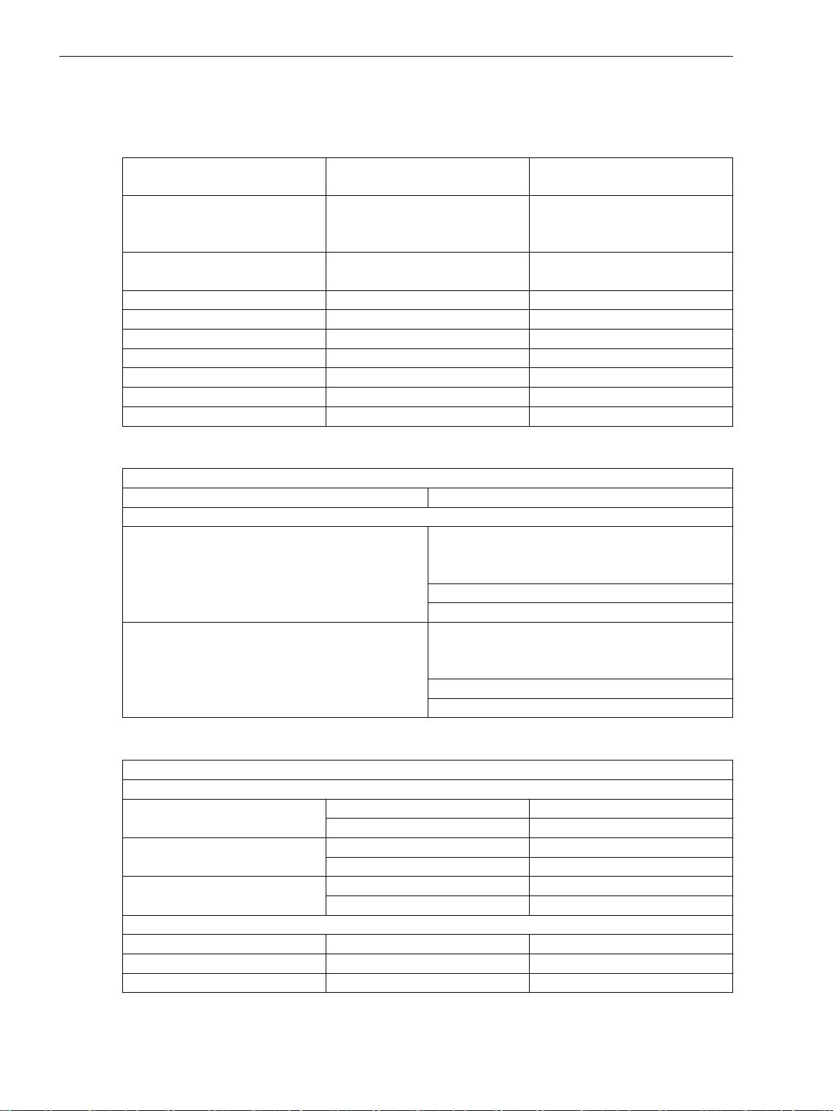
Transmission Times
Priority 1
Response time, total approx.
For 2 ends Minimum 8 ms
For 3 ends Minimum 10 ms
For 6 ends Minimum 15 ms
Dropout times, total approx.
For 2 ends Typical 20 ms
For 3 ends Typical 20 ms
For 6 ends Typical 26 ms
1114 SIPROTEC 5, High-Voltage Bay Controller, Manual
:
Typical 10 ms
Typical 14 ms
Typical 18 ms
C53000-G5040-C015-A, Edition 05.2018
Page 20
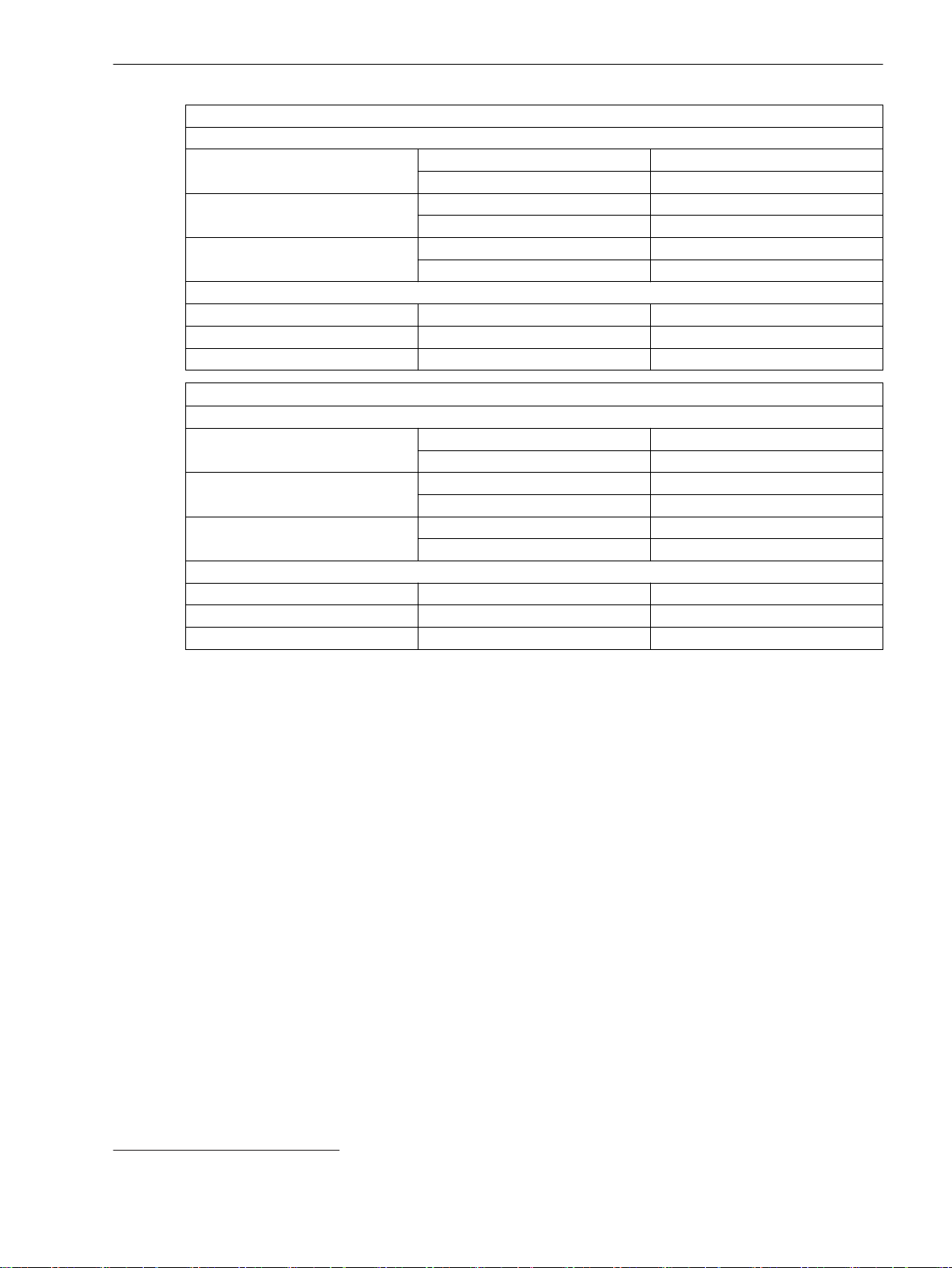
11.2 Protection Interface and Protection Topology
Priority 2:
Response time, total approx.
For 2 ends Minimum 9 ms
Typical 16 ms
For 3 ends Minimum 12 ms
Typical 18 ms
For 6 ends Minimum 17 ms
Typical 23 ms
Dropout times, total approx.
For 2 ends Typical 24 ms
For 3 ends Typical 25 ms
For 6 ends Typical 32 ms
Technical Data
Priority 3
33
Response time, total approx.
For 2 ends Minimum
Typical 100 ms
For 3 ends Minimum
Typical 150 ms
For 6 ends Minimum
Typical 200 ms
Dropout times, total approx.
For 2 ends Typical 100 ms
For 3 ends Typical 150 ms
For 6 ends Typical 200 ms
33
Times cannot be determined because the signals are transmitted in fragments.
SIPROTEC 5, High-Voltage Bay Controller, Manual 1115
C53000-G5040-C015-A, Edition 05.2018
Page 21
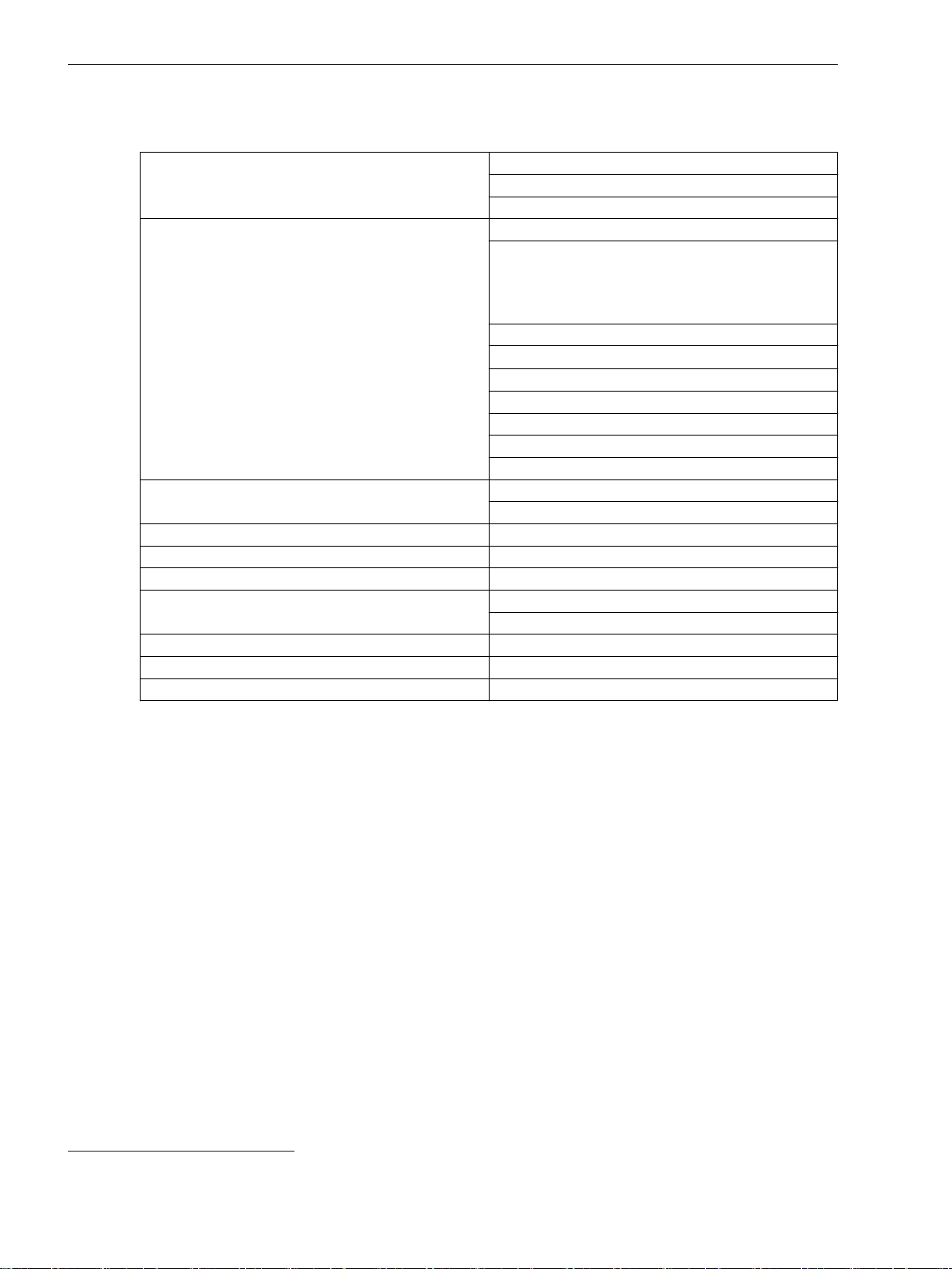
Technical Data
11.3 Date and Time Synchronization
11.3
Date and Time Synchronization
Date format DD.MM.YYYY (Europe)
MM/DD/YYYY (USA)
YYYY-MM-DD (China)
Time source 1, time source 2 None
IRIG-B 002(003)
IRIG-B 006(007)
IRIG-B 005(004) with extension according to
IEEE C37.118-2005
DCF77
PI (protection interface)
SNTP
IEC 60870-5-103
DNP3
IEEE 1588
T104
Time zone 1, time zone 2 Local
UTC
Failure indication after 0 s to 3600 s
Time zone and daylight saving time Manually setting the time zones
Time zone offset with respect to GMT -720 min to 840 min
Switching over to daylight saving time Active
Inactive
Beginning of daylight saving time Input: day and time
End of daylight saving time Input: day and time
Offset daylight saving time 0 min to 120 min [steps of 15]
34
34
If provided
1116 SIPROTEC 5, High-Voltage Bay Controller, Manual
C53000-G5040-C015-A, Edition 05.2018
Page 22
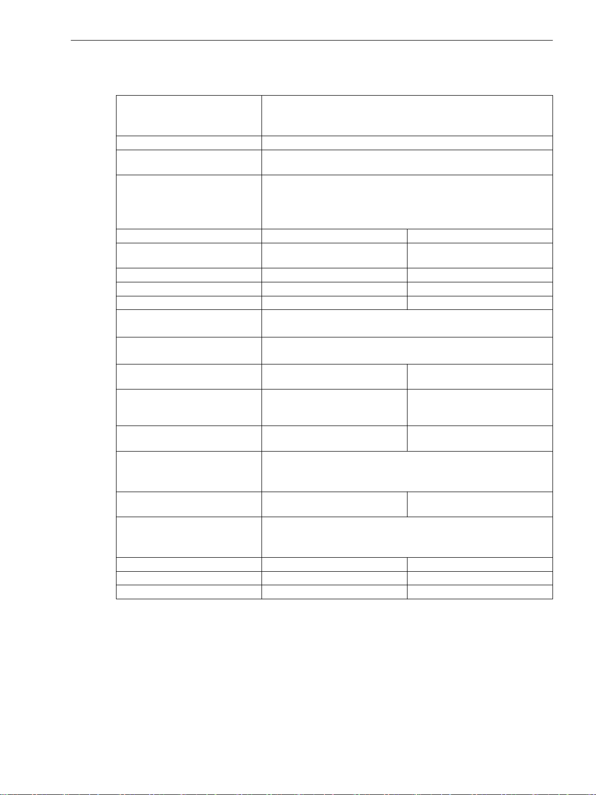
Technical Data
11.4 Automatic Reclosing
11.4
Automatic Reclosing
Function specifications Cyclic automatic reclosing function
Automatic reclosing function with adaptive dead time (ADT)
Operation with External Automatic Reclosing Function
Number of reclosings Max. 8, per individual settings
Type (depending on the order
variation)
Operating mode of the automatic
reclosing function
Reclaim time after reclosing 0.50 s to 300.00 s Increments of 0.01 s
Blocking time after dynamic
blocking
Blocking time after manual closure 0.00 s to 300.00 s Increments of 0.01 s
Start supervision time 0.01 s to 300.00 s Increments of 0.01 s
Circuit-breaker supervision time 0.01 s to 300.00 s Increments of 0.01 s
Evolving-fault detection With trip command
Reaction to evolving faults Blocks automatic reclosing function
Action times (separated for all
cycles)
Dead times after trip command
(separated for all types and all
cycles)
Dead time after evolving-fault
detection (separated for all cycles)
Synchrocheck after 3-pole dead
time
Transmission delay, inter close
command
Dead-line check/reduced dead time Without
Voltage supervision warning time 0.10 s to 30.00 s Increments of 0.01 s
Limiting value for fault-free line 0.3 V to 340.0 V Increments of 0.1 V
Limiting value for zero potential 0.3 V to 340.0 V Increments of 0.1 V
1-pole, 3-pole, or 1-/3-pole
With trip command, without action time
With trip command, with action time
With pickup, without action time
With pickup, with action time
0.5 s -
with Pickup
Start, evolving fault, dead time
0.00 s to 300.00 s or oo (ineffec-
tive)
0.00 s to 1 800.00 s or oo (ineffec-
tive)
0.00 s to 1 800.00 s Increments of 0.01 s
None
Internal
External
0.00 s to 300.00 s or oo (ineffec-
tive)
Reduced dead time (VWE)
Dead line checking
Increments of 0.01 s
Increments of 0.01 s
Increments of 0.01 s
SIPROTEC 5, High-Voltage Bay Controller, Manual 1117
C53000-G5040-C015-A, Edition 05.2018
Page 23

Technical Data
11.5 Phasor Measurement Unit
11.5
Accuracy
Data Transfer
Phasor Measurement Unit
IEEE Standard for Synchrophasor
Measurements
IEEE Std C37.118.1aTM-2014
IEEE Standard for Synchrophasor
Data transfer
IEEE Std C37.118.2TM-2011
1118 SIPROTEC 5, High-Voltage Bay Controller, Manual
C53000-G5040-C015-A, Edition 05.2018
Page 24
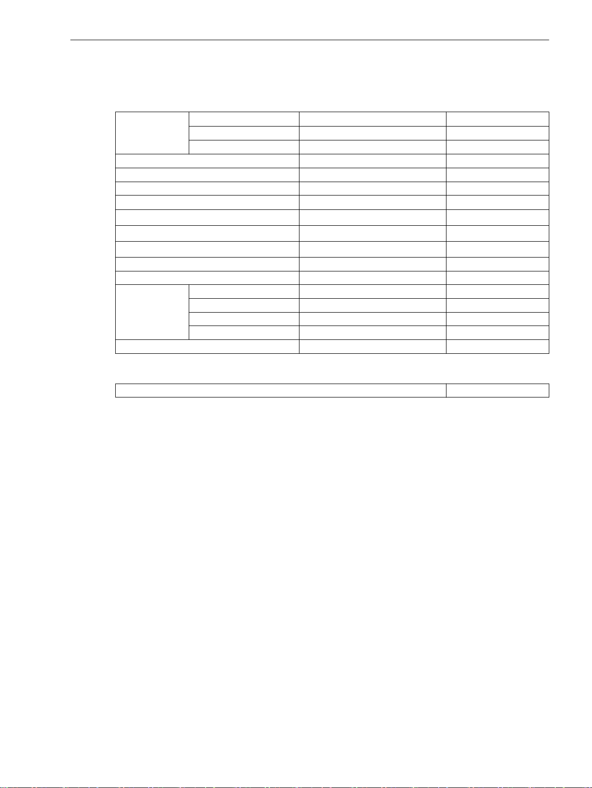
Technical Data
11.6 Circuit-Breaker Wear Monitoring
11.6
Circuit-Breaker Wear Monitoring
Setting Values
Threshold value
CB opening time 0.001 s to 0.500 s Increments of 0.001 s
CB break time 0.001 s to 0.600 s Increments of 0.001 s
CB make time 0.001 s to 0.600 s Increments of 0.001 s
Exponent for the ΣIx method
Switching cycles at I
Rated short-circuit breaking current I
Switching cycles at I
Level of warning 1 1 % to 100 % Increments of 1 %
Level of warning 2 1 % to 100 % Increments of 1 %
Operating
current threshold
Delay correction time -0.050 s to 0.050 s Increments of 0.001 s
ΣIx-method stage
0 to 10 000 000 Increments of 1
2P-method stage 0 to 10 000 000 Increments of 1
I2t-method stage
0.00 I/Ir*s to 21 400 000.00 I/Ir*s Increments of 0.01
1.0 to 3.0 Increments of 0.1
rated
sc
sc
100 to 1 000 000 Increments of 1
10 to 100 000 Increments of 1
1 to 1000 Increments of 1
1 A @ 50 and 100 Irated 0.030 A to 35.000 A Increments of 0.001 A
5 A @ 50 and 100 Irated 0.15 A to 175.00 A Increments of 0.01 A
1 A @ 1.6 Irated 0.001 A to 1.600 A Increments of 0.001 A
5 A @ 1.6 Irated 0.005 A to 8.000 A Increments of 0.001 A
Tolerances
Tolerance of the measured value make time
± 2 ms
SIPROTEC 5, High-Voltage Bay Controller, Manual 1119
C53000-G5040-C015-A, Edition 05.2018
Page 25
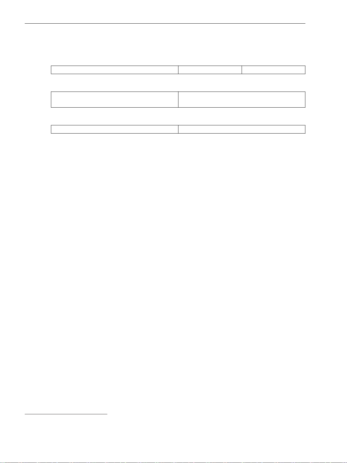
Technical Data
11.7 External Trip Initiation
11.7
Setting Values
Times
Tolerance
External Trip Initiation
Tripping delay 0.00 s to 60.00 s Increments of 0.01 s
Operate time with time delay = 0 ms
- At initiation via binary input signal
Sequence tolerance for delay times 1 % of the setting value or 10 ms
Approx. 10 ms + OOT 35.
35
OOT (Output Operating Time) additional delay of the output medium used, for example 5 ms with fast relays, see chapter 11.1.4 Relay
Outputs
1120 SIPROTEC 5, High-Voltage Bay Controller, Manual
C53000-G5040-C015-A, Edition 05.2018
Page 26
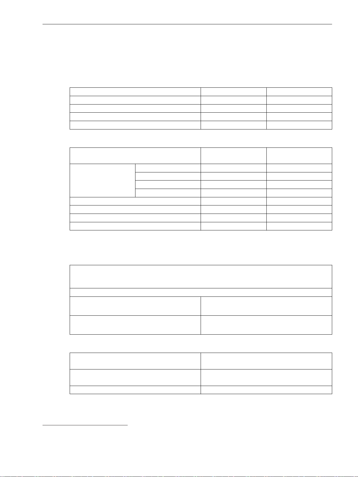
Technical Data
11.8 Overcurrent Protection, Phases
11.8
11.8.1
Overcurrent Protection, Phases
Stage with Definite-Time Characteristic Curve
Setting Value for the Function Block Filter
h(0) -100.000 to 100.000 Increments of 0.001
h(1) -100.000 to 100.000 Increments of 0.001
h(2) -100.000 to 100.000 Increments of 0.001
h(3) -100.000 to 100.000 Increments of 0.001
h(4) -100.000 to 100.000 Increments of 0.001
Setting Values for Protection Stage
Method of measurement Fundamental component
Threshold value
36
1 A @ 50 and 100 Irated 0.030 A to 35.000 A Increments of 0.001 A
5 A @ 50 and 100 Irated 0.15 A to 175.00 A Increments of 0.01 A
1 A @ 1.6 Irated 0.001 A to 1.600 A Increments of 0.001 A
5 A @ 1.6 Irated 0.005 A to 8.000 A Increments of 0.001 A
Dropout ratio 0.90 to 0.99 Increments of 0.01
Operate delay 0.00 s to 100.00 s Increments of 0.01 s
Dropout delay 0.00 s to 60.00 s Increments of 0.01 s
Pickup delay 0.00 s to 60.00 s Increments of 0.01 s
–
RMS value
Dropout
Times
The greater dropout differential (= | pickup value – dropout value |) of the following 2 criteria
applies:
Dropout differential derived from the parameter
Dropout ratio
If this parameter is not available, a dropout ratio of 95 % applies for overcurrent and of 105 % for undercurrent functionality.
Minimum absolute dropout differential
Protection-class current transformer 15 mA sec. (I
75 mA sec. (I
Instrument current transformer 0.5 mA sec. (I
2.5 mA sec. (I
Operate time with time delay = 0 ms
Approx. 25 ms + OOT 37 at 50 Hz
= 1 A) or
rated
= 5 A)
rated
rated
rated
= 1 A) or
= 5 A)
Approx. 22 ms + OOT at 60 Hz
Extension of the operate time during operation with
Approx. 10 ms
transformer inrush-current detection
Dropout time Approx. 20 ms + OOT
36
If you have selected the method of measurement = RMS value, do not set the threshold value under 0.1 l
37
OOT (Output Operating Time): additional delay of the output medium used, for example 5 ms with fast relays
SIPROTEC 5, High-Voltage Bay Controller, Manual 1121
C53000-G5040-C015-A, Edition 05.2018
rated,sec
.
Page 27
Technical Data
11.8 Overcurrent Protection, Phases
Frequency Operating Range
Tolerances
0.9 ≤ f/f
10 Hz ≤ f < 0.9 f
1.1 f
f < 10 Hz
≤ 1.1 According to specified tolerances
rated
Slightly expanded tolerances
< f ≤ 80 Hz
rated
rated
Active
f > 80 Hz
Currents, method of measurement = fundamental
component
1 % of the setting value or 5 mA (I
or 25 mA (I
= 5 A), (f
rated
rated
± 10 %)
rated
Currents, method of measurement = RMS value, no filter applied
(33 % harmonics, in relation to fundamental component)
Up to 30th harmonic 1 % of the setting value or 5 mA (I
Up to 50th harmonic, f
Up to 50th harmonic, f
or 25 mA (I
= 50 Hz 3 % of the setting value or 20 mA (I
rated
or 100 mA (I
= 60 Hz 4 % of the setting value or 20 mA (I
rated
or 100 mA (I
= 5 A), (f
rated
rated
rated
= 5 A), (f
= 5 A), (f
rated
rated
rated
rated
± 10 %)
± 10 %)
± 10 %)
Currents, method of measurement = RMS value
with filter for the compensation of the amplitude attenuation due to the anti-aliasing filter
(33 % harmonics, in relation to the fundamental component)
Up to 30 harmonic 1 % of the setting value or 5 mA (I
Up to 50th harmonic, f
Up to 50th harmonic, f
or 25 mA (I
= 50 Hz 2 % of the setting value or 10 mA (I
rated
or 50 mA (I
= 60 Hz 3 % of the setting value or 20 mA (I
rated
or 100 mA (I
= 5 A), (f
rated
= 5 A), (f
rated
rated
= 5 A), (f
rated
rated
rated
rated
± 10 %)
± 10 %)
± 10 %)
Currents, method of measurement = RMS value
with filter for the gain of harmonics (including compensation of the amplitude attenuation
(33 % harmonics, in relation to the fundamental component)
Up to 30 harmonic 1.5 % of the setting value or 10 mA (I
Up to 50th harmonic, f
Up to 50th harmonic, f
or 50 mA (I
= 50 Hz 3% of the setting value or 20 mA (I
rated
or 100 mA (I
= 60 Hz 4 % of the setting value or 20 mA (I
rated
or 100 mA (I
= 5 A), (f
rated
rated
rated
= 5 A), (f
= 5 A), (f
rated
rated
rated
± 10 %)
rated
± 10 %)
± 10 %)
Time delays 1 % of the setting value or 10 ms
= 1 A)
= 1 A)
rated
rated
= 1 A)
rated
rated
38
rated
39
rated
= 1 A)
= 1 A)
= 1 A)
= 1 A)
= 1 A)
= 1 A)
40
= 1 A)
41
38
In case that the filter response exactly matches the user-defined gain factors
39
In case that the user-defined gain factor is set below 3. The tolerance increases, if the gain factor is larger.
40
In case that the user-defined gain factor is set below 7. The tolerance increases, if the gain factor is larger.
41
In case that the user-defined gain factor is set below 7. The tolerance increases, if the gain factor is larger.
1122 SIPROTEC 5, High-Voltage Bay Controller, Manual
C53000-G5040-C015-A, Edition 05.2018
Page 28
Influencing Variables for Thresholds
Technical Data
11.8 Overcurrent Protection, Phases
Transient excess pickup in method of measurement =
fundamental component, for τ > 100 ms (with
complete unbalance)
11.8.2
Stage with Inverse-Time Characteristic Curve
Setting Value for the Function Block Filter
h(0) -100.000 to 100.000 Increments of 0.001
h(1) -100.000 to 100.000 Increments of 0.001
h(2) -100.000 to 100.000 Increments of 0.001
h(3) -100.000 to 100.000 Increments of 0.001
h(4) -100.000 to 100.000 Increments of 0.001
Setting Values for Protection Stage
Method of measurement Fundamental component
Threshold value 1 A @ 50 and 100 Irated 0.030 A to 35.000 A Increments of 0.001 A
5 A @ 50 and 100 Irated 0.15 A to 175.00 A Increments of 0.01 A
1 A @ 1.6 Irated 0.001 A to 1.600 A Increments of 0.001 A
5 A @ 1.6 Irated 0.005 A to 8.000 A Increments of 0.001 A
Dropout Disk emulation
Time multiplier 0.00 to 15.00 Increments of 0.01
Pickup delay 0.00 s to 60.00 s Increments of 0.01 s
< 5 %
–
RMS value
–
Instantaneous
Dropout
The greater dropout differential (= | pickup value – dropout value |) of the following 2 criteria
applies:
Dropout
95 % of 1.1 ⋅ threshold value
Minimum absolute dropout differential
Protection-class current transformer 15 mA sec. (I
75 mA sec. (I
Instrument current transformer 0.5 mA sec. (I
2.5 mA sec. (I
Reset of the Integration Timer
Instantaneous
With dropout
Disk emulation Approx. < 0.90 ⋅ threshold value
Operate Curves and Dropout-Time Characteristic Curves according to IEC
Extension of the operate time during operation with
Approx. 10 ms
transformer inrush-current detection
= 1 A) or
rated
= 5 A)
rated
rated
rated
= 1 A) or
= 5 A)
SIPROTEC 5, High-Voltage Bay Controller, Manual 1123
C53000-G5040-C015-A, Edition 05.2018
Page 29
Technical Data
11.8 Overcurrent Protection, Phases
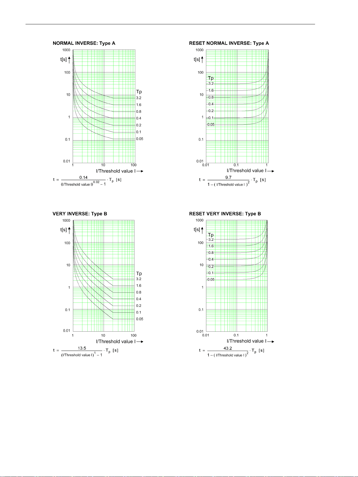
[dwocpki1-080213-01.tif, 1, en_US]
Figure 11-1
Operate Curves and Dropout-Time Characteristic Curves According to IEC
1124 SIPROTEC 5, High-Voltage Bay Controller, Manual
C53000-G5040-C015-A, Edition 05.2018
Page 30
Technical Data
11.8 Overcurrent Protection, Phases
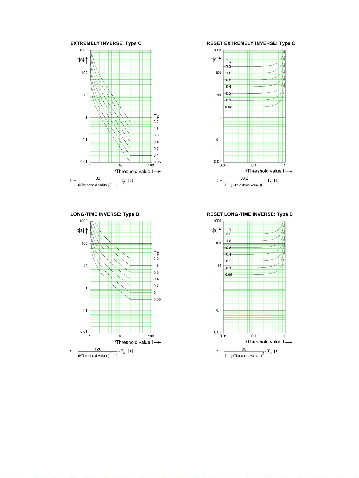
[dwocpki2-080213-01.tif, 1, en_US]
Figure 11-2
Operate Curves and Dropout-Time Characteristic Curves According to IEC
SIPROTEC 5, High-Voltage Bay Controller, Manual 1125
C53000-G5040-C015-A, Edition 05.2018
Page 31
Technical Data
11.8 Overcurrent Protection, Phases
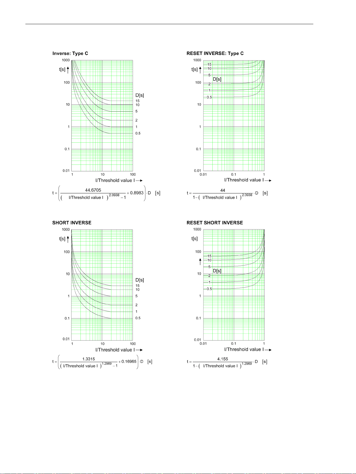
Operate Curves and Dropout-Time Characteristic Curves According to ANSI/IEEE
[dwocpka1-080213-01.tif, 2, en_US]
Figure 11-3
1126 SIPROTEC 5, High-Voltage Bay Controller, Manual
Operate Curves and Dropout-Time Characteristic Curves According to ANSI/IEEE
C53000-G5040-C015-A, Edition 05.2018
Page 32
Technical Data
11.8 Overcurrent Protection, Phases
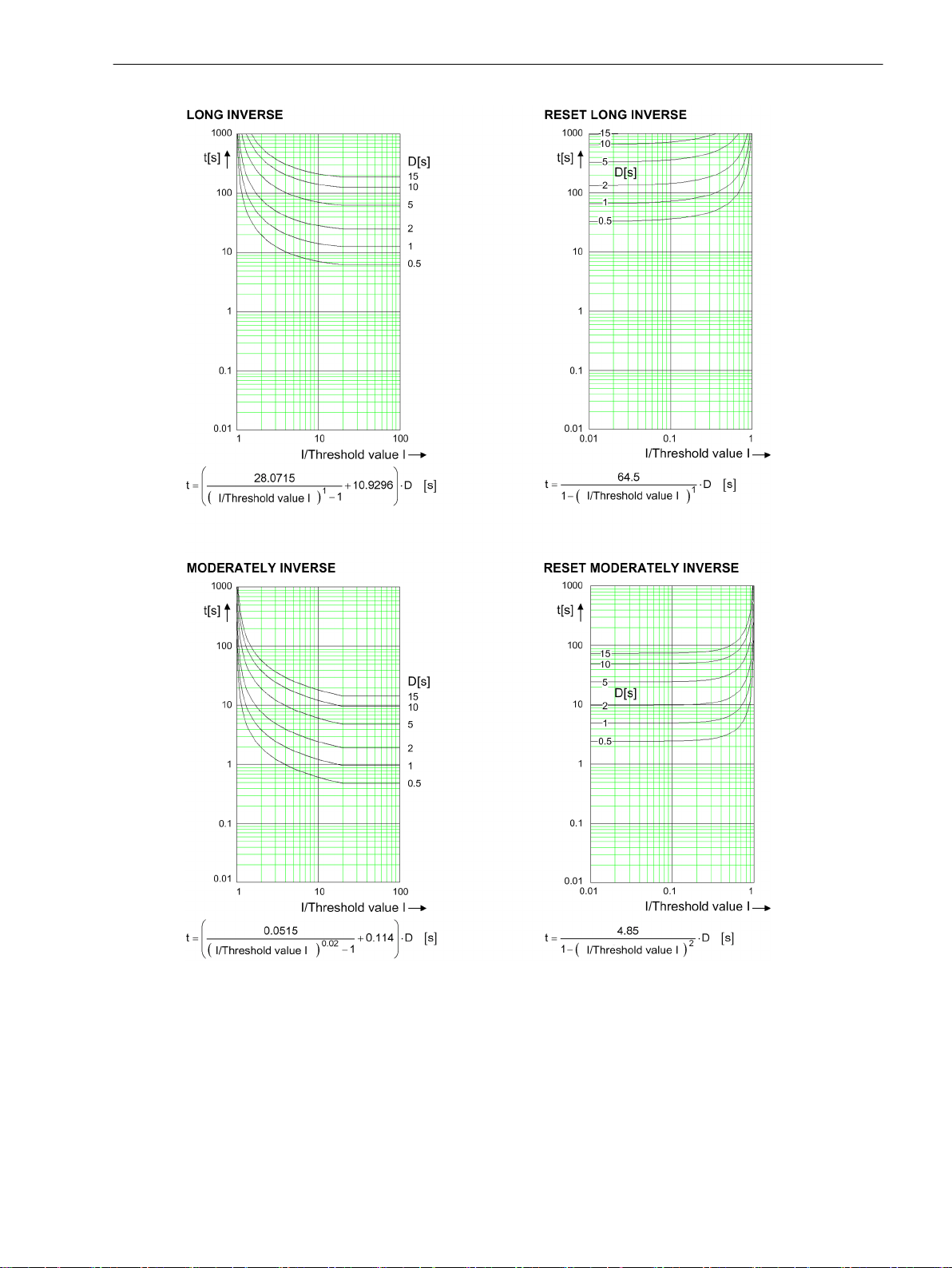
[dwocpka2-080213-01.tif, 2, en_US]
Figure 11-4
Operate Curves and Dropout-Time Characteristic Curves According to ANSI/IEEE
SIPROTEC 5, High-Voltage Bay Controller, Manual 1127
C53000-G5040-C015-A, Edition 05.2018
Page 33
Technical Data
11.8 Overcurrent Protection, Phases
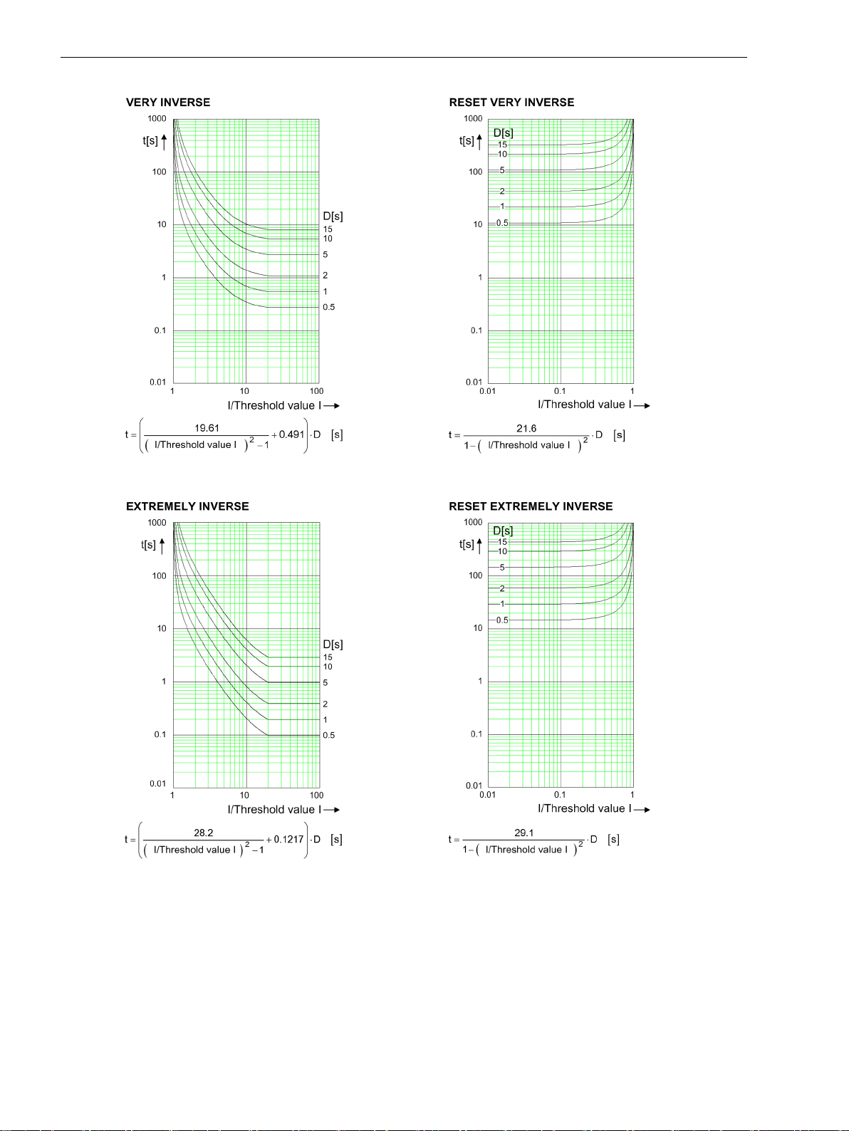
[dwocpka3-080213-01.tif, 2, en_US]
Figure 11-5
Tripping Characteristic Curves and Dropout Characteristic Curves According to ANSI/IEEE
1128 SIPROTEC 5, High-Voltage Bay Controller, Manual
C53000-G5040-C015-A, Edition 05.2018
Page 34
Technical Data
11.8 Overcurrent Protection, Phases
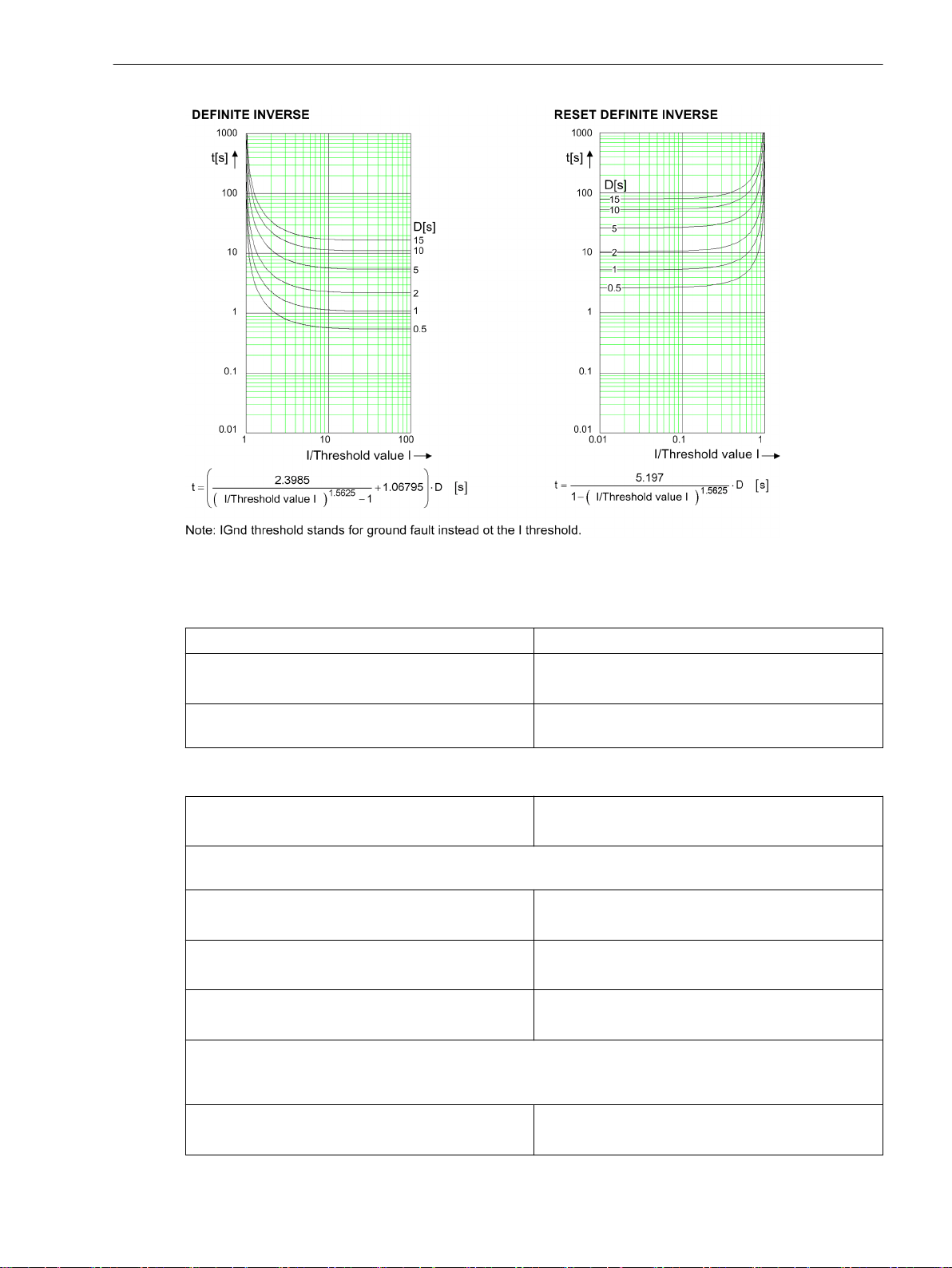
[dwocpka4-080213-01.tif, 2, en_US]
Figure 11-6
Operate Curves and Dropout-Time Characteristic Curves According to ANSI/IEEE
Frequency Operating Range
0.9 ≤ f/f
≤ 1.1 According to specified tolerances
rated
10 Hz ≤ f < 0.9 f
1.1 f
< f ≤ 80 Hz
rated
f < 10 Hz
f > 80 Hz
Tolerances
Currents, method of measurement = fundamental
component
Currents, method of measurement = RMS value, no filter applied
(33 % harmonics, in relation to fundamental component)
Up to 30th harmonic 1 % of the setting value or 5 mA (I
Up to 50th harmonic, f
Up to 50th harmonic, f
Currents, method of measurement = RMS value
with filter for the compensation of the amplitude attenuation due to the anti-aliasing filter
(33 % harmonics, in relation to the fundamental component)
Up to 30 harmonic 1 % of the setting value or 5 mA (I
rated
Slightly expanded tolerances
Active
1 % of the setting value or 5 mA (I
or 25 mA (I
or 25 mA (I
= 50 Hz 3 % of the setting value or 20 mA (I
rated
or 100 mA (I
= 60 Hz 4 % of the setting value or 20 mA (I
rated
or 100 mA (I
or 25 mA (I
= 5 A), (f
rated
= 5 A), (f
rated
rated
rated
= 5 A), (f
rated
= 5 A), (f
= 5 A), (f
rated
rated
rated
rated
rated
± 10 %)
± 10 %)
± 10 %)
± 10 %)
± 10 %)
rated
rated
rated
rated
rated
= 1 A)
= 1 A)
= 1 A)
= 1 A)
= 1 A)
SIPROTEC 5, High-Voltage Bay Controller, Manual 1129
C53000-G5040-C015-A, Edition 05.2018
Page 35
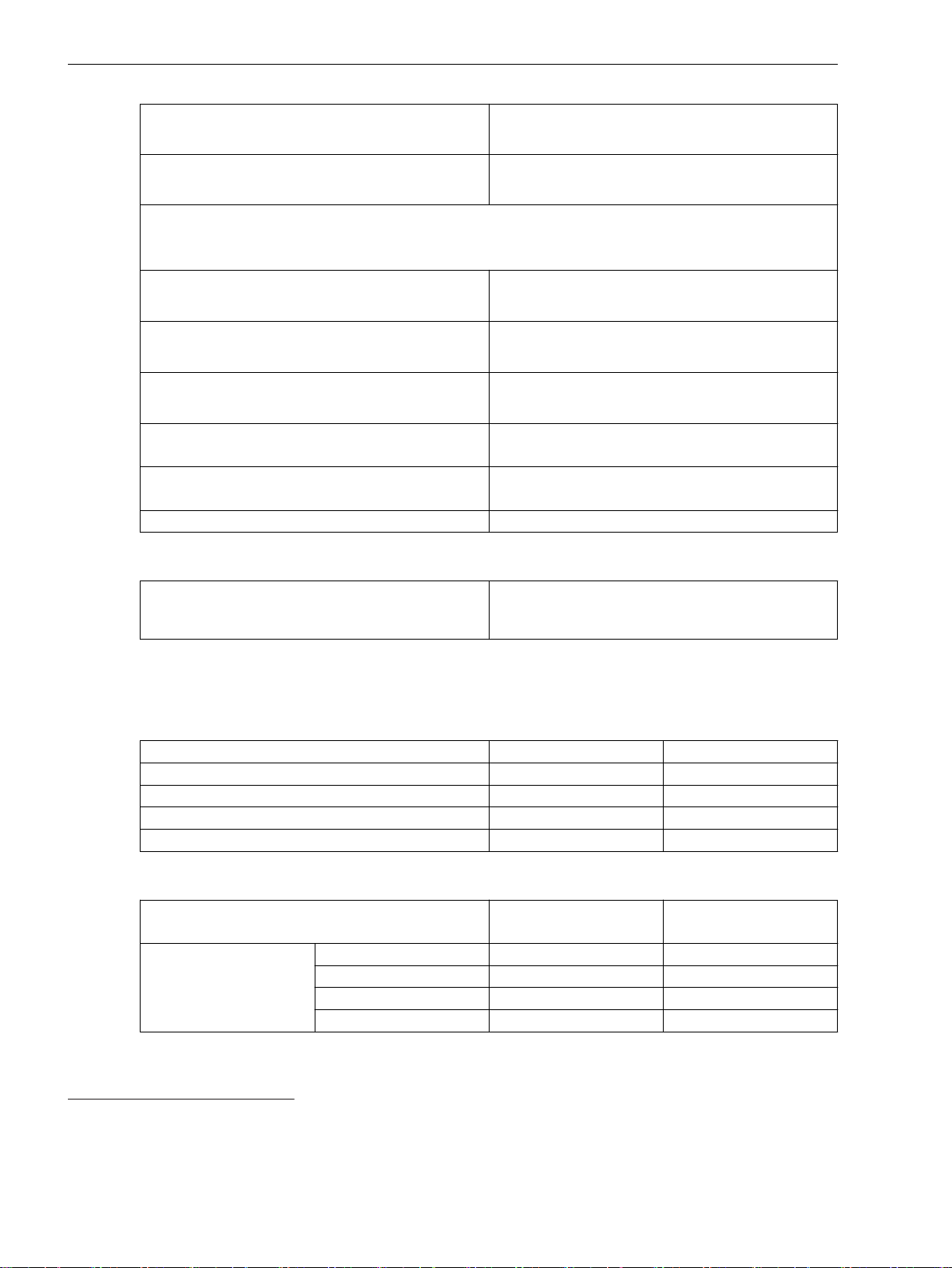
Technical Data
11.8 Overcurrent Protection, Phases
Up to 50th harmonic, f
Up to 50th harmonic, f
rated
rated
Currents, method of measurement = RMS value
with filter for the gain of harmonics (including compensation of the amplitude attenuation
(33 % harmonics, in relation to the fundamental component)
Up to 30 harmonic 1.5 % of the setting value or 10 mA (I
Up to 50th harmonic, f
Up to 50th harmonic, f
rated
rated
Operate time for 2 ≤ I/I threshold value ≤ 20 5 % of the reference (calculated) value
Dropout time for I/I threshold value ≤ 0.90 5 % of the reference (calculated) value
Time delays 1 % of the setting value or 10 ms
Influencing Variables for Thresholds
= 50 Hz 2 % of the setting value or 10 mA (I
or 50 mA (I
= 5 A), (f
rated
rated
± 10 %)
= 60 Hz 3 % of the setting value or 20 mA (I
or 100 mA (I
or 50 mA (I
rated
= 5 A), (f
rated
= 5 A), (f
rated
rated
± 10 %)
± 10 %)
= 50 Hz 3% of the setting value or 20 mA (I
or 100 mA (I
= 5 A), (f
rated
± 10 %)
rated
= 60 Hz 4 % of the setting value or 20 mA (I
or 100 mA (I
= 5 A), (f
rated
± 10 %)
rated
+2 % current tolerance or 30 ms
+2 % current tolerance or 30 ms
rated
rated
42
rated
rated
= 1 A)
= 1 A)
rated
43
= 1 A)
44
= 1 A)
45
= 1 A)
Transient excess pickup in method of measurement =
fundamental component, for τ > 100 ms (with
complete unbalance)
11.8.3
Stage with User-Defined Characteristic Curve
Setting Value for the Function Block Filter
h(0)
h(1) -100.000 to 100.000 Increments of 0.001
h(2) -100.000 to 100.000 Increments of 0.001
h(3) -100.000 to 100.000 Increments of 0.001
h(4) -100.000 to 100.000 Increments of 0.001
Setting Values for Protection Stage
Method of measurement
Threshold value 1 A @ 50 and 100 Irated 0.030 A to 35.000 A Increments of 0.001 A
5 A @ 50 and 100 Irated 0.15 A to 175.00 A Increments of 0.01 A
1 A @ 1.6 Irated 0.001 A to 1.600 A Increments of 0.001 A
5 A @ 1.6 Irated 0.005 A to 8.000 A Increments of 0.001 A
< 5 %
-100.000 to 100.000 Increments of 0.001
Fundamental component
–
RMS value
42
In case that the filter response exactly matches the user-defined gain factors
43
In case that the user-defined gain factor is set below 3. The tolerance increases, if the gain factor is larger.
44
In case that the user-defined gain factor is set below 7. The tolerance increases, if the gain factor is larger.
45
In case that the user-defined gain factor is set below 7. The tolerance increases, if the gain factor is larger.
1130 SIPROTEC 5, High-Voltage Bay Controller, Manual
C53000-G5040-C015-A, Edition 05.2018
Page 36
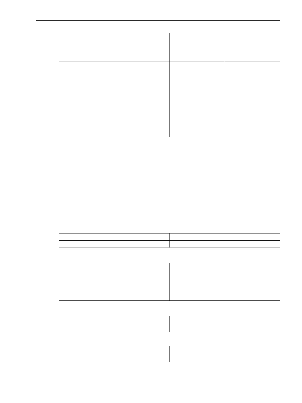
Dropout
Technical Data
11.8 Overcurrent Protection, Phases
Absolute pickup value 1 A @ 50 and 100 Irated 0.000 A to 35.000 A Increments of 0.001 A
5 A @ 50 and 100 Irated 0.00 A to 175.00 A Increments of 0.01 A
1 A @ 1.6 Irated 0.000 A to 1.600 A Increments of 0.001 A
5 A @ 1.6 Irated 0.000 A to 8.000 A Increments of 0.001 A
Dropout Disk emulation
–
Instantaneous
Time multiplier 0.05 to 15.00 Increments of 0.01
Number of value pairs for the operate curve 2 to 30 Increments of 1
X values of the operate curve 1.00 p.u. to 20.00 p.u. Increments of 0.01 p.u.
Y values of the operate curve 0.00 s to 999.00 s Increments of 0.01 s
Number of value pairs for the dropout characteristic
2 to 30 Increments of 1
curve
X values of the dropout characteristic curve 0.05 p.u. to 0.95 p.u. Increments of 0.01 p.u.
Y values of the dropout characteristic curve 0.00 s to 999.00 s Increments of 0.01 s
Additional time delay 0.00 s to 60.00 s Increments of 0.01 s
The greater dropout differential (= | pickup value – dropout value |) of the following 2 criteria
applies:
Dropout 95 % of 1.1 ⋅ threshold value or 95 % of the absolute
Minimum absolute dropout differential
Protection-class current transformer 15 mA sec. (I
Instrument current transformer 0.5 mA sec. (I
Reset of the Integration Timer
Instantaneous
Disk emulation Approx. < 0.90 ⋅ threshold value
Frequency Operating Range
0.9 ≤ f/f
10 Hz ≤ f < 0.9 f
1.1 f
≤ 1.1 According to specified tolerances
rated
rated
< f ≤ 80 Hz
rated
f < 10 Hz
f > 80 Hz
Tolerances
pickup value
= 1 A) or
rated
75 mA sec. (I
2.5 mA sec. (I
rated
rated
rated
= 5 A)
= 1 A) or
= 5 A)
With dropout
Slightly expanded tolerances
Active
Currents, method of measurement = fundamental
component
1 % of the setting value or 5 mA (I
or 25 mA (I
= 5 A), (f
rated
rated
± 10 %)
rated
= 1 A)
Currents, method of measurement = RMS value, no filter applied
(33 % harmonics, in relation to fundamental component)
Up to 30th harmonic 1 % of the setting value or 5 mA (I
or 25 mA (I
SIPROTEC 5, High-Voltage Bay Controller, Manual 1131
C53000-G5040-C015-A, Edition 05.2018
= 5 A), (f
rated
rated
± 10 %)
rated
= 1 A)
Page 37
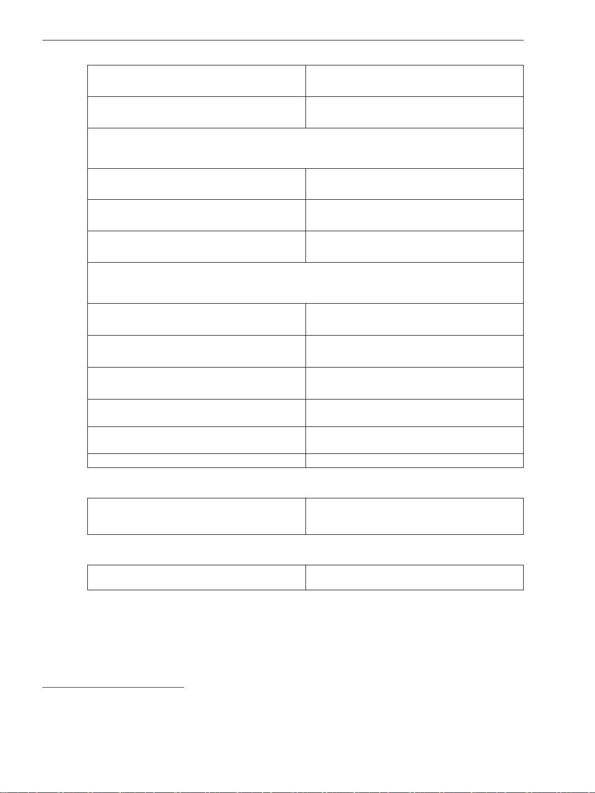
Technical Data
11.8 Overcurrent Protection, Phases
Up to 50th harmonic, f
Up to 50th harmonic, f
= 50 Hz 3 % of the setting value or 20 mA (I
rated
or 100 mA (I
= 60 Hz 4 % of the setting value or 20 mA (I
rated
or 100 mA (I
= 5 A), (f
rated
= 5 A), (f
rated
rated
rated
rated
± 10 %)
rated
± 10 %)
Currents, method of measurement = RMS value
with filter for the compensation of the amplitude attenuation due to the anti-aliasing filter
(33 % harmonics, in relation to the fundamental component)
Up to 30 harmonic 1 % of the setting value or 5 mA (I
Up to 50th harmonic, f
Up to 50th harmonic, f
or 25 mA (I
= 50 Hz 2 % of the setting value or 10 mA (I
rated
or 50 mA (I
= 60 Hz 3 % of the setting value or 20 mA (I
rated
or 100 mA (I
= 5 A), (f
rated
= 5 A), (f
rated
rated
= 5 A), (f
rated
rated
rated
rated
± 10 %)
rated
± 10 %)
rated
± 10 %)
Currents, method of measurement = RMS value
with filter for the gain of harmonics (including compensation of the amplitude attenuation
46
(33 % harmonics, in relation to the fundamental component)
Up to 30 harmonic 1.5 % of the setting value or 10 mA (I
47
rated
± 10 %)
rated
± 10 %)
Up to 50th harmonic, f
Up to 50th harmonic, f
or 50 mA (I
= 50 Hz 3% of the setting value or 20 mA (I
rated
or 100 mA (I
= 60 Hz 4 % of the setting value or 20 mA (I
rated
or 100 mA (I
= 5 A), (f
rated
rated
rated
= 5 A), (f
= 5 A), (f
rated
rated
rated
± 10 %)
Operate time for 2 ≤ I/I threshold value ≤ 20 5 % of the reference (calculated) value
+2 % current tolerance or 30 ms
Dropout time for I/I threshold value ≤ 0.90 5 % of the reference (calculated) value
+2 % current tolerance or 30 ms
Time delays 1 % of the setting value or 10 ms
= 1 A)
= 1 A)
= 1 A)
= 1 A)
= 1 A)
= 1 A)
rated
= 1 A)
48
= 1 A)
49
Influencing Variables for Thresholds
Transient excess pickup in method of measurement =
< 5 %
fundamental component, for τ > 100 ms (with
complete unbalance)
Operate Curves and Dropout-Time Characteristic Curves According to IEC
Extension of the operate time during operation with
Approx. 10 ms
transformer inrush-current detection
46
In case that the filter response exactly matches the user-defined gain factors
47
In case that the user-defined gain factor is set below 3. The tolerance increases, if the gain factor is larger.
48
In case that the user-defined gain factor is set below 7. The tolerance increases, if the gain factor is larger.
49
In case that the user-defined gain factor is set below 7. The tolerance increases, if the gain factor is larger.
1132 SIPROTEC 5, High-Voltage Bay Controller, Manual
C53000-G5040-C015-A, Edition 05.2018
Page 38
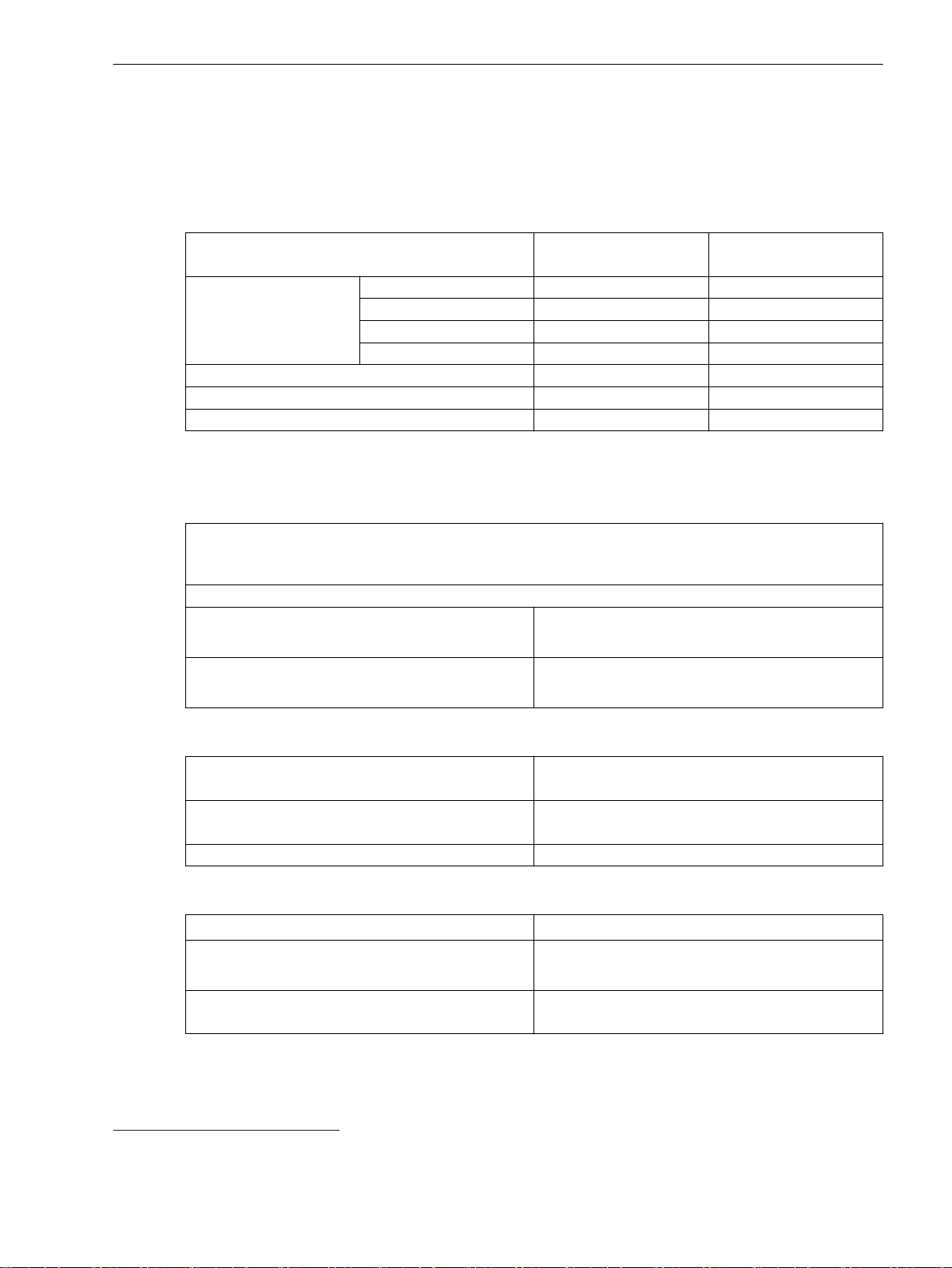
Technical Data
11.9 Overcurrent Protection, Ground
11.9
11.9.1
Overcurrent Protection, Ground
Stage with Definite-Time Characteristic Curve
Setting Values
Method of measurement Fundamental component
Threshold value
Dropout ratio 0.90 to 0.99 Increments of 0.01
Time delay 0.00 s to 60.00 s Increments of 0.01 s
Dropout delay 0.00 s to 60.00 s Increments of 0.01 s
Dropout
The greater dropout differential (= | pickup value – dropout value |) of the following 2 criteria
applies:
Dropout differential derived from the parameter Dropout ratio
If this parameter is not available, a dropout ratio of 95 % applies for overcurrent and of 105 % for undercurrent functionality.
Minimum absolute dropout differential
Protection-class current transformer 15 mA sec. (I
Instrument current transformer 0.5 mA sec. (I
–
RMS value
50
1 A @ 50 and 100 Irated 0.010 A to 35.000 A Increments of 0.001 A
5 A @ 50 and 100 Irated 0.05 A to 175.00 A Increments of 0.01 A
1 A @ 1.6 Irated 0.001 A to 1.600 A Increments of 0.001 A
5 A @ 1.6 Irated 0.002 A to 8.000 A Increments of 0.001 A
= 1 A) or
rated
75 mA sec. (I
2.5 mA sec. (I
rated
rated
rated
= 5 A)
= 1 A) or
= 5 A)
Times
Operate time with time delay = 0 ms
Approx. 25 ms + OOT51 at 50 Hz
Approx. 22 ms + OOT at 60 Hz
Extension of the operate time during operation with
Approx. 10 ms
transformer inrush-current detection
Dropout time Approx. 20 ms + OOT
Frequency Operating Range
0.9 ≤ f/f
10 Hz ≤ f < 0.9 f
1.1 f
f < 10 Hz
≤ 1.1 According to specified tolerances
rated
Slightly expanded tolerances
< f ≤ 80 Hz
rated
rated
Active
f > 80 Hz
50
If you have selected the method of measurement = RMS value, do not set the threshold value under 0.1 l
51
OOT (Output Operating Time): additional delay of the output medium used, see Chapter 11.1.4 Relay Outputs
rated,sec
.
SIPROTEC 5, High-Voltage Bay Controller, Manual 1133
C53000-G5040-C015-A, Edition 05.2018
Page 39
Technical Data
11.9 Overcurrent Protection, Ground
Tolerances
3I0 measured via I452, method of measurement =
fundamental component
3I0 measured via I453, method of measurement = RMS value
(33 % harmonics, in relation to fundamental component)
Up to 30th harmonic 1 % of the setting value or 5 mA (I
Up to 50th harmonic, f
Up to 50th harmonic, f
rated
rated
Time delays 1 % of the setting value or 10 ms
Influencing Variables for Thresholds
Transient excess pickup in method of measurement =
fundamental component, for τ > 100 ms (with
complete unbalance)
11.9.2
Stage with Inverse-Time Characteristic Curve
Setting Values
1 % of the setting value or 5 mA (I
or 25 mA (I
or 25 mA (I
= 5 A), (f
rated
= 5 A), (f
rated
rated
rated
± 10 %)
± 10 %)
= 50 Hz 3 % of the setting value or 20 mA (I
or 100 mA (I
= 5 A), (f
rated
rated
± 10 %)
= 60 Hz 4 % of the setting value or 20 mA (I
or 100 mA (I
= 5 A), (f
rated
rated
± 10 %)
< 5 %
rated
rated
rated
rated
= 1 A)
= 1 A)
= 1 A)
= 1 A)
Dropout
Method of measurement
Fundamental component
–
RMS value
Threshold value
54
1 A @ 50 and 100 Irated 0.010 A to 35.000 A Increments of 0.001 A
5 A @ 50 and 100 Irated 0.05 A to 175.00 A Increments of 0.01 A
1 A @ 1.6 Irated 0.001 A to 1.600 A Increments of 0.001 A
5 A @ 1.6 Irated 0.002 A to 8.000 A Increments of 0.001 A
Dropout Disk emulation
–
Instantaneous
Time multiplier 0.00 to 15.00 Increments of 0.01
Minimum time of the curve 0.00 s to 1.00 s Increments of 0.01 s
Additional time delay 0.00 s to 60.00 s Increments of 0.01 s
The greater dropout differential (= | pickup value – dropout value |) of the following 2 criteria
applies:
Dropout
95 % of 1.1 ⋅ threshold value
Minimum absolute dropout differential
Protection-class current transformer 15 mA sec. (I
75 mA sec. (I
Instrument current transformer 0.5 mA sec. (I
2.5 mA sec. (I
= 1 A) or
rated
= 5 A)
rated
rated
rated
= 1 A) or
= 5 A)
52
Slightly expanded tolerances will occur during the calculation of 3I0, maximum factor of 2
53
Slightly expanded tolerances will occur during the calculation of 3I0, maximum factor of 2
54
If you have selected the method of measurement = RMS value, do not set the threshold value under 0.1 l
1134 SIPROTEC 5, High-Voltage Bay Controller, Manual
C53000-G5040-C015-A, Edition 05.2018
rated,sec
.
Page 40
Reset of the Integration Timer
Instantaneous With dropout
Disk emulation Approx. < 0.90 ⋅ threshold value
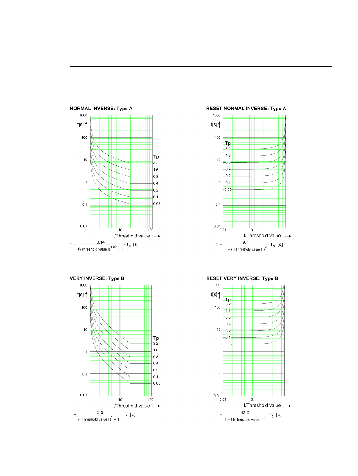
Operate Curves and Dropout Characteristic Curves According to IEC
Technical Data
11.9 Overcurrent Protection, Ground
Extension of the operate time during operation with
transformer inrush-current detection
Approx. 10 ms
[dwocpki1-080213-01.tif, 1, en_US]
Figure 11-7
SIPROTEC 5, High-Voltage Bay Controller, Manual 1135
C53000-G5040-C015-A, Edition 05.2018
Operate Curves and Dropout Characteristic Curves According to IEC
Page 41
Technical Data
11.9 Overcurrent Protection, Ground
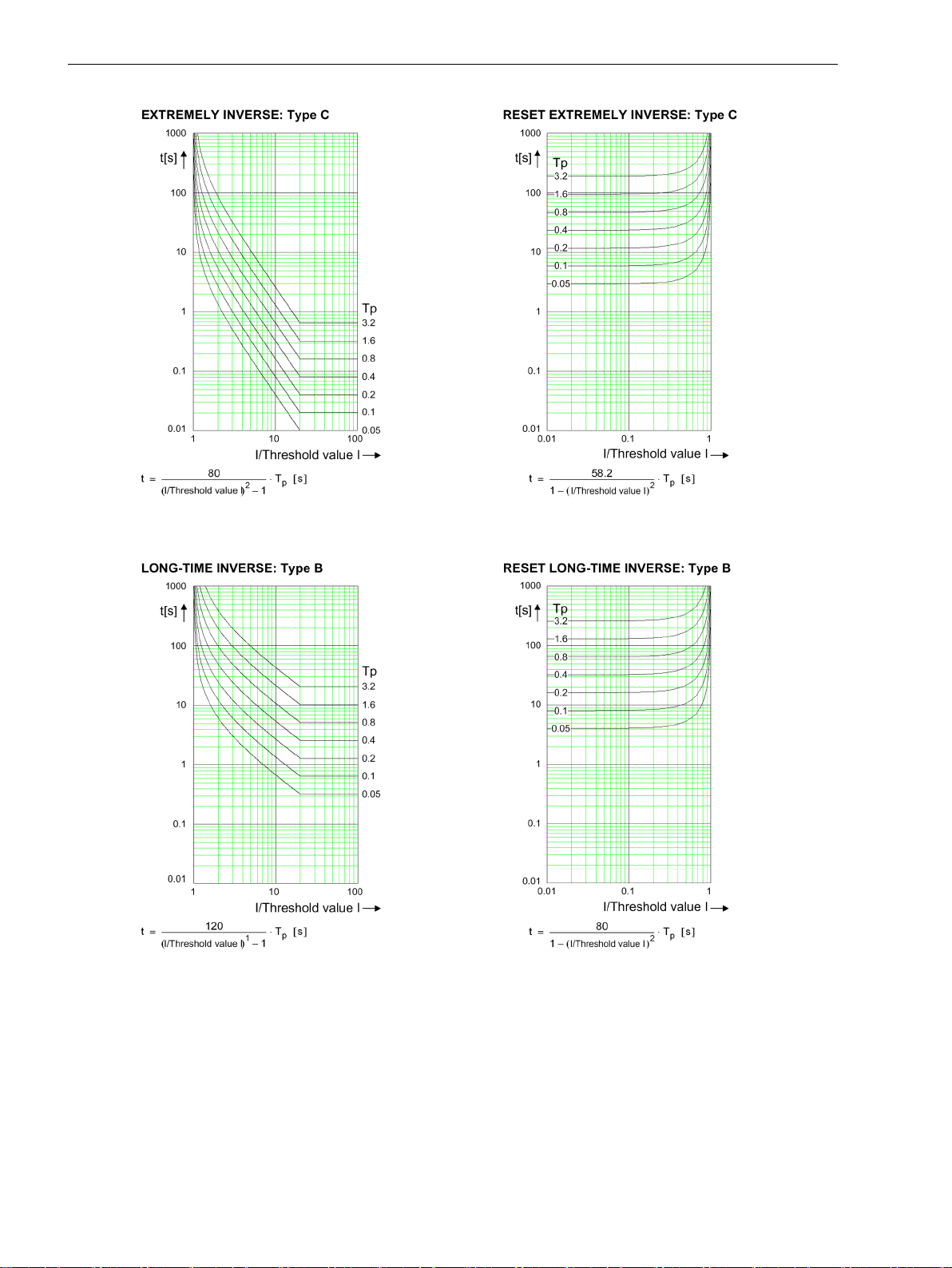
[dwocpki2-080213-01.tif, 1, en_US]
Figure 11-8
Operate Curves and Dropout Characteristic Curves According to IEC
1136 SIPROTEC 5, High-Voltage Bay Controller, Manual
C53000-G5040-C015-A, Edition 05.2018
Page 42
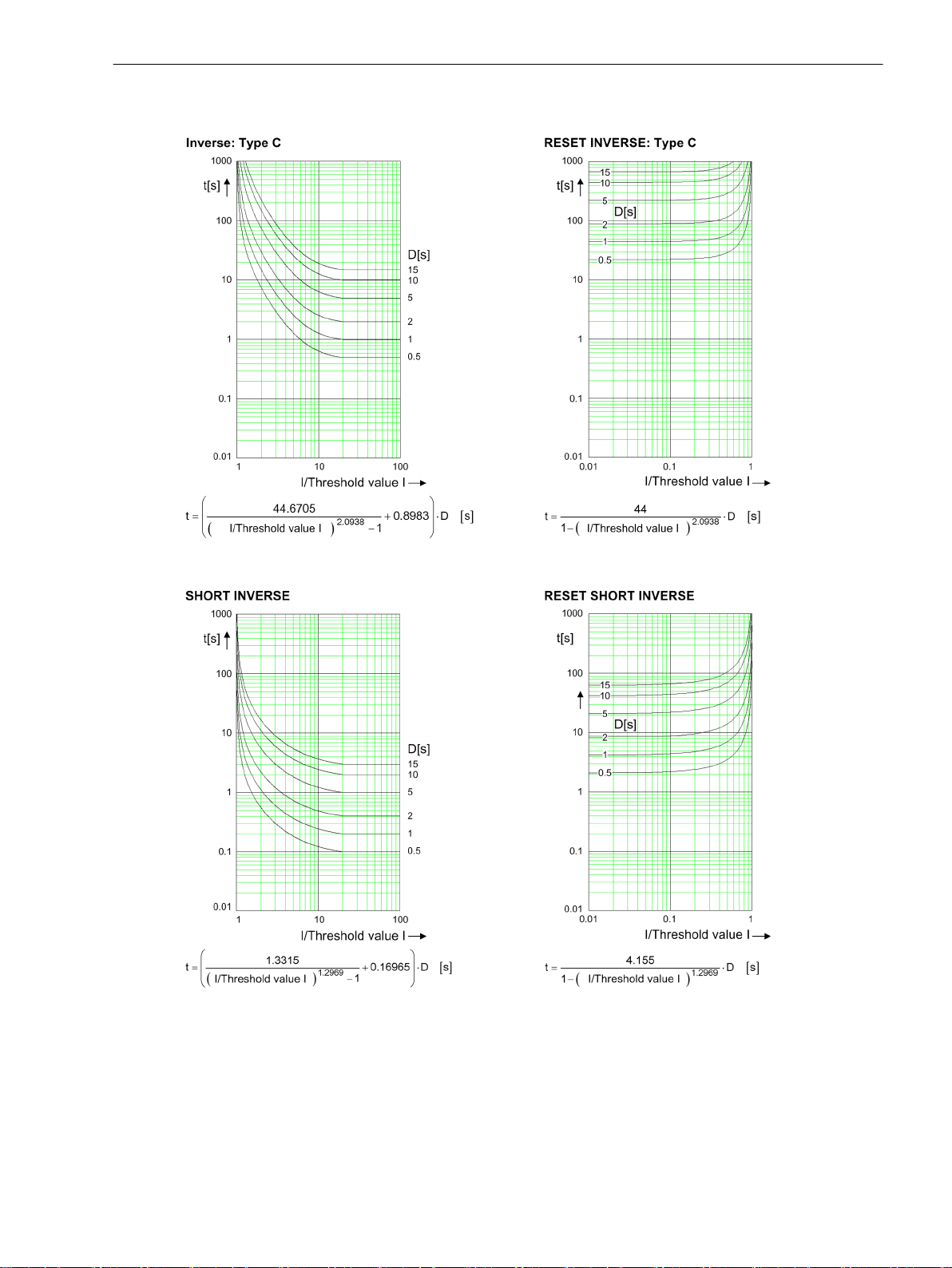
Operate Curves and Dropout Characteristic Curves According to ANSI/IEEE
Technical Data
11.9 Overcurrent Protection, Ground
[dwocpka1-080213-01.tif, 2, en_US]
Figure 11-9
SIPROTEC 5, High-Voltage Bay Controller, Manual 1137
C53000-G5040-C015-A, Edition 05.2018
Operate Curves and Dropout Characteristic Curves According to ANSI/IEEE
Page 43
Technical Data
11.9 Overcurrent Protection, Ground
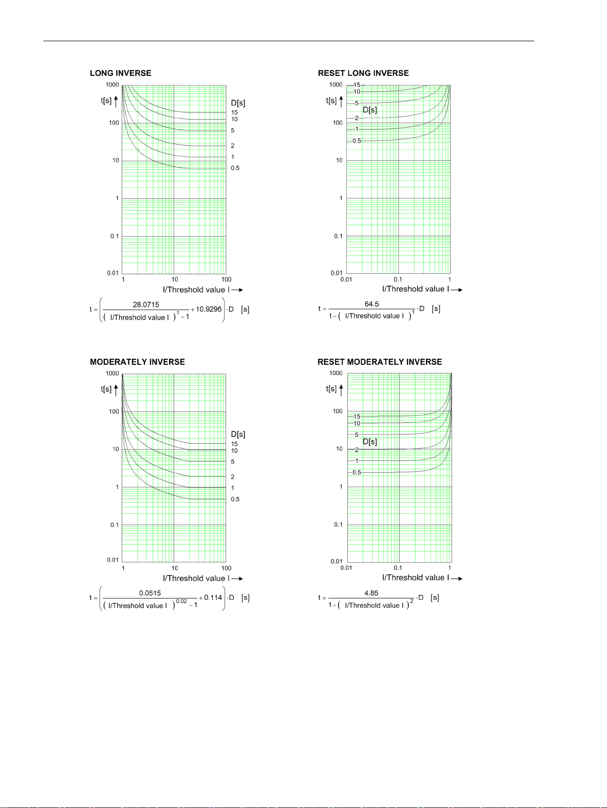
[dwocpka2-080213-01.tif, 2, en_US]
Figure 11-10
Operate Curves and Dropout Characteristic Curves According to ANSI/IEEE
1138 SIPROTEC 5, High-Voltage Bay Controller, Manual
C53000-G5040-C015-A, Edition 05.2018
Page 44
Technical Data
11.9 Overcurrent Protection, Ground
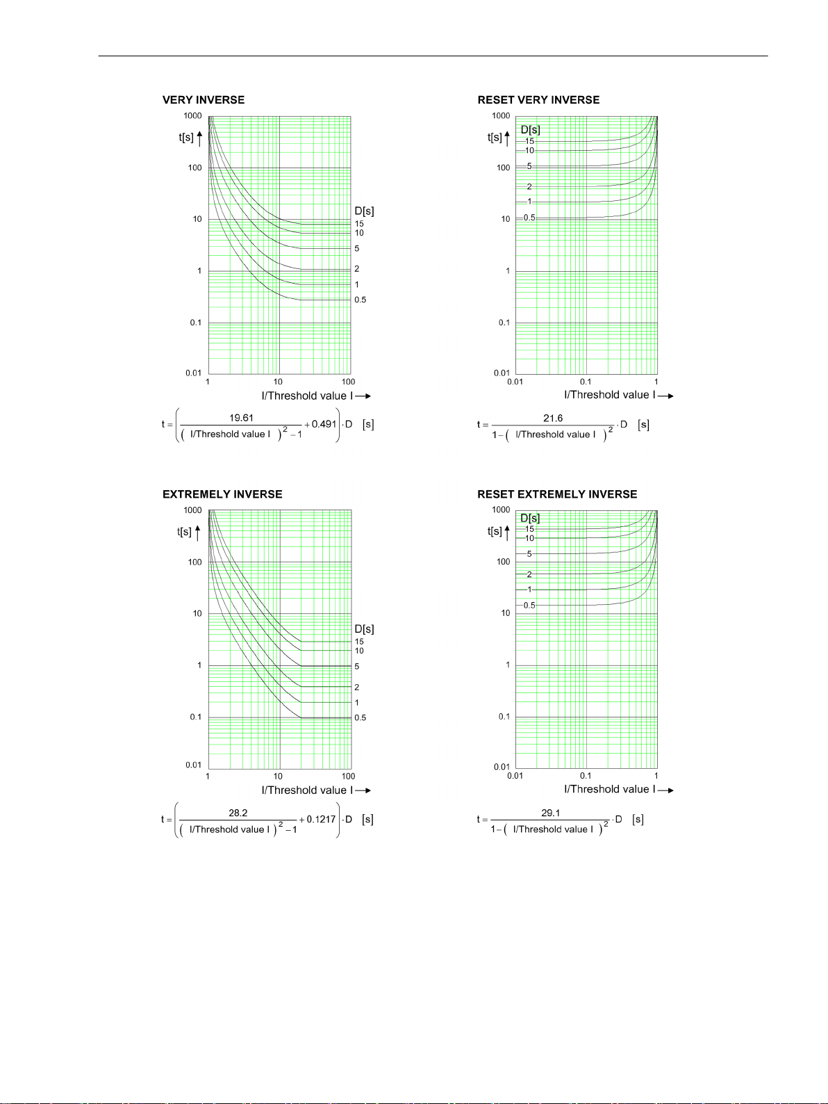
[dwocpka3-080213-01.tif, 2, en_US]
Figure 11-11
Operate Curves and Dropout Characteristic Curves According to ANSI/IEEE
SIPROTEC 5, High-Voltage Bay Controller, Manual 1139
C53000-G5040-C015-A, Edition 05.2018
Page 45
Technical Data
11.9 Overcurrent Protection, Ground
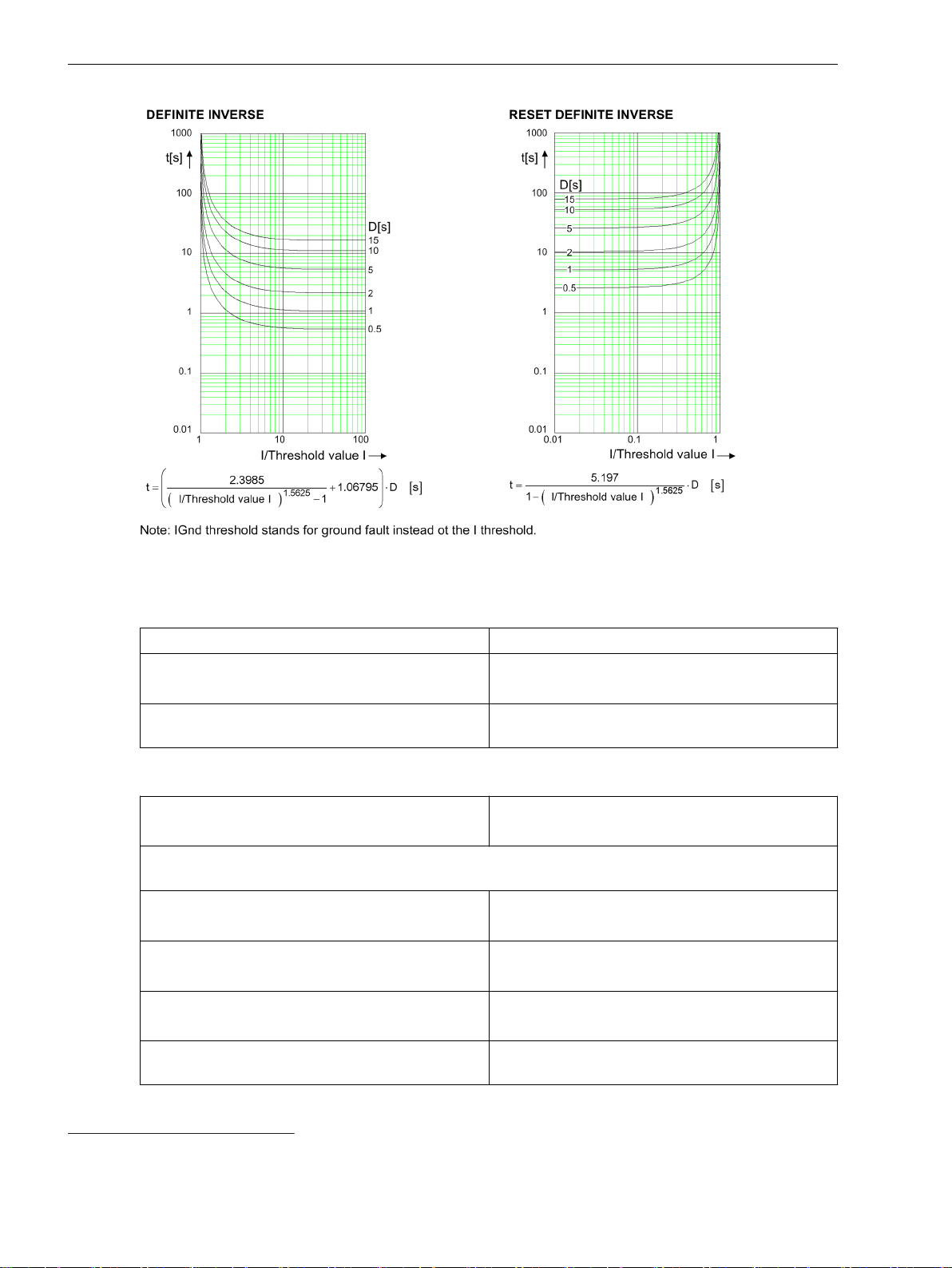
[dwocpka4-080213-01.tif, 2, en_US]
Figure 11-12
Operate Curves and Dropout Characteristic Curves According to ANSI/IEEE
Frequency Operating Range
0.9 ≤ f/f
≤ 1.1 According to specified tolerances
rated
10 Hz ≤ f < 0.9 f
1.1 f
< f ≤ 80 Hz
rated
f < 10 Hz
f > 80 Hz
Tolerances
3I0 measured via I4
fundamental component
3I0 measured via I456, method of measurement = RMS value
(33 % harmonics, in relation to fundamental component)
Up to 30th harmonic 1 % of the setting value or 5 mA (I
Up to 50th harmonic, f
Up to 50th harmonic, f
Operate time for 2 ≤ I/I threshold value ≤ 20 5 % of the reference (calculated) value
rated
55
, method of measurement =
= 50 Hz 3 % of the setting value or 20 mA (I
rated
= 60 Hz 4 % of the setting value or 20 mA (I
rated
Slightly expanded tolerances
Active
1 % of the setting value or 5 mA (I
or 25 mA (I
or 25 mA (I
or 100 mA (I
or 100 mA (I
= 5 A), (f
rated
= 5 A), (f
rated
rated
rated
= 5 A), (f
= 5 A), (f
rated
rated
rated
rated
± 10 %)
± 10 %)
± 10 %)
± 10 %)
+2 % current tolerance or 30 ms
rated
rated
rated
rated
= 1 A)
= 1 A)
= 1 A)
= 1 A)
55
Insignificantly increased tolerances will occur during the calculation of 3I0, maximum factor of 2
56
Insignificantly increased tolerances will occur during the calculation of 3I0, maximum factor of 2
1140 SIPROTEC 5, High-Voltage Bay Controller, Manual
C53000-G5040-C015-A, Edition 05.2018
Page 46
Dropout time for 2 ≤ I/threshold value I ≤ 0.90 5 % of the reference (calculated) value
Influencing Variables for Thresholds
Technical Data
11.9 Overcurrent Protection, Ground
+2 % current tolerance or 30 ms
Transient excess pickup in method of measurement =
fundamental component, for τ > 100 ms (with
complete unbalance)
11.9.3
Stage with User-Defined Characteristic Curve
Setting Values
Method of measurement Fundamental component
Threshold value 1 A @ 50 and 100 Irated 0.010 A to 35.000 A Increments of 0.001 A
Absolute pickup value 1 A @ 50 and 100 Irated 0.000 A to 35.000 A Increments of 0.001 A
Dropout Disk emulation
Time multiplier 0.05 to 15.00 Increments of 0.01
Number of value pairs for the operate curve 2 to 30 Increments of 1
X values of the operate curve 1.00 p.u. to 20.00 p. u. Increments of 0.01 p.u.
Y values of the operate curve 0.00 s to 999.00 s Increments of 0.01 s
Number of value pairs for the dropout characteristic
curve
X values of the dropout characteristic curve 0.05 p.u. to 0.95 p. u. Increments of 0.01 p.u.
Y values of the dropout characteristic curve 0.00 s to 999.00 s Increments of 0.01 s
Additional time delay 0.00 s to 60.00 s Increments of 0.01 s
< 5 %
–
RMS value
5 A @ 50 and 100 Irated 0.05 A to 175.00 A Increments of 0.01 A
1 A @ 1.6 Irated 0.001 A to 1.600 A Increments of 0.001 A
5 A @ 1.6 Irated 0.002 A to 8.000 A Increments of 0.001 A
5 A @ 50 and 100 Irated 0.00 A to 175.00 A Increments of 0.01 A
1 A @ 1.6 Irated 0.000 A to 1.600 A Increments of 0.001 A
5 A @ 1.6 Irated 0.000 A to 8.000 A Increments of 0.001 A
–
Instantaneous
2 to 30 Increments of 1
Dropout
The greater dropout differential (= | pickup value – dropout value |) of the following 2 criteria
applies:
Dropout
95 % of 1.1 ⋅ threshold value or 95 % of the absolute
pickup value
Minimum absolute dropout differential
Protection-class current transformer 15 mA sec. (I
75 mA sec. (I
Instrument current transformer 0.5 mA sec. (I
2.5 mA sec. (I
= 1 A) or
rated
= 5 A)
rated
rated
rated
= 1 A) or
= 5 A)
Reset of the Integration Timer
Instantaneous
With dropout
Disk emulation Approx. < 0.90 ⋅ threshold value
SIPROTEC 5, High-Voltage Bay Controller, Manual 1141
C53000-G5040-C015-A, Edition 05.2018
Page 47
Technical Data
11.9 Overcurrent Protection, Ground
Frequency Operating Range
Tolerances
0.9 ≤ f/f
10 Hz ≤ f < 0.9 f
1.1 f
f < 10 Hz
≤ 1.1 According to specified tolerances
rated
Slightly expanded tolerances
< f ≤ 80 Hz
rated
rated
Active
f > 80 Hz
3I0 measured via I457, method of measurement =
fundamental component
1 % of the setting value or 5 mA (I
or 25 mA (I
= 5 A), (f
rated
rated
± 10 %)
rated
3I0 measured via I458, method of measurement = RMS value
(33 % harmonics, in relation to fundamental component)
Up to 30th harmonic 1 % of the setting value or 5 mA (I
Up to 50th harmonic, f
Up to 50th harmonic, f
or 25 mA (I
= 50 Hz 3 % of the setting value or 20 mA (I
rated
or 100 mA (I
= 60 Hz 4 % of the setting value or 20 mA (I
rated
or 100 mA (I
= 5 A), (f
rated
rated
rated
= 5 A), (f
= 5 A), (f
rated
rated
rated
rated
± 10 %)
rated
± 10 %)
rated
± 10 %)
Operate time for 2 ≤ I/I threshold value ≤ 20 5 % of the reference (calculated) value
+2 % current tolerance or 30 ms
Dropout time for I/I threshold value ≤ 0.90 5 % of the reference (calculated) value
+2 % current tolerance or 30 ms
= 1 A)
= 1 A)
= 1 A)
= 1 A)
Influencing Variables for Thresholds
Transient excess pickup in method of measurement =
< 5 %
fundamental component, for τ > 100 ms (with
complete unbalance)
Operate Curves and Dropout-Time Characteristic Curves According to IEC
Extension of the operate time during operation with
Approx. 10 ms
transformer inrush-current detection
57
Insignificantly increased tolerances will occur during the calculation of 3I0, maximum factor of 2
58
Insignificantly increased tolerances will occur during the calculation of 3I0, maximum factor of 2
1142 SIPROTEC 5, High-Voltage Bay Controller, Manual
C53000-G5040-C015-A, Edition 05.2018
Page 48
Technical Data
11.10 Directional Overcurrent Protection, Phases
11.10
11.10.1
Directional Overcurrent Protection, Phases
Stage with Definite-Time Characteristic Curve
Setting Values
Rotation angle of the reference voltage -180° to +180° Increments of 1°
Directional mode Forward
Method of measurement Fundamental component
Threshold value
Dropout ratio 0.90 to 0.99 Increments of 0.01
Time delay 0.00 s to 60.00 s Increments of 0.01 s
Dropout delay 0.00 s to 60.00 s Increments of 0.01 s
Dropout
The greater dropout differential (= | pickup value – dropout value |) of the following 2 criteria
applies:
–
Reverse
–
RMS value
59
1 A @ 50 and 100 Irated 0.030 A to 35.000 A Increments of 0.001 A
5 A @ 50 and 100 Irated 0.15 A to 175.00 A Increments of 0.01 A
1 A @ 1.6 Irated 0.001 A to 1.600 A Increments of 0.001 A
5 A @ 1.6 Irated 0.005 A to 8.000 A Increments of 0.001 A
Dropout differential derived from the parameter
If this parameter is not available, a dropout ratio of 95 % applies for overcurrent and of 105 % for undercurrent functionality.
Minimum absolute dropout differential
Protection-class current transformer 15 mA sec. (I
Instrument current transformer 0.5 mA sec. (I
Direction Determination
Type
Forward range V
Dropout differential forward/reverse range 1°
Directional sensitivity Unlimited for 1 and 2-phase short circuits
Times
Operate time with time delay = 0 ms
Dropout ratio
= 1 A) or
rated
75 mA sec. (I
2.5 mA sec. (I
rated
rated
rated
= 5 A)
= 1 A) or
= 5 A)
With healthy voltages
With voltage memory 2 s
±88°
ref,rot
Dynamically unlimited, stationary for 3-phase short
circuits
Approx. 13 V phase-to-phase
Approx. 37 ms + OOT 60 at 50 Hz
Approx. 22 ms + OOT at 60 Hz
59
If you have selected the method of measurement = RMS value, do not set the threshold value under 0.1 l
60
OOT (Output Operating Time): additional delay of the output medium used, for example 5 ms with fast relays
SIPROTEC 5, High-Voltage Bay Controller, Manual 1143
C53000-G5040-C015-A, Edition 05.2018
rated,sec
.
Page 49
Technical Data
11.10 Directional Overcurrent Protection, Phases
Extension of the operate time during operation with
transformer inrush-current detection
Dropout time Approx. 20 ms + OOT
Frequency Operating Range
0.9 ≤ f/f
≤ 1.1 According to specified tolerances
rated
10 Hz ≤ f < 0.9 f
1.1 f
< f ≤ 80 Hz
rated
f < 10 Hz
f > 80 Hz
Tolerances
Currents, method of measurement = fundamental
component
Currents, method of measurement = RMS value
(33 % harmonics, in relation to fundamental component)
Up to 30th harmonic 1 % of the setting value or 5 mA (I
Up to 50th harmonic, f
Up to 50th harmonic, f
Time delay 1 % of the setting value or 10 ms
Direction-determination angle error 1 °
rated
Approx. 10 ms
Slightly expanded tolerances
Active
1 % of the setting value or 5 mA (I
or 25 mA (I
or 25 mA (I
= 50 Hz 3 % of the setting value or 20 mA (I
rated
or 100 mA (I
= 60 Hz 4 % of the setting value or 20 mA (I
rated
or 100 mA (I
= 5 A), (f
rated
= 5 A), (f
rated
rated
rated
= 5 A), (f
= 5 A), (f
rated
rated
rated
rated
± 10 %)
± 10 %)
± 10 %)
± 10 %)
rated
rated
rated
rated
= 1 A)
= 1 A)
= 1 A)
= 1 A)
Influencing Variables for Thresholds
Transient excess pickup in method of measurement =
< 5 %
fundamental component, for τ > 100 ms (with
complete unbalance)
11.10.2
Stage with Inverse-Time Characteristic Curve
Setting Values
Rotation angle of the reference voltage
-180° to +180° Increments of 1°
Directional mode Forward
Backward
Method of measurement Fundamental component
RMS value
Threshold value
61
1 A @ 50 and 100 Irated 0.030 A to 35.000 A Increments of 0.001 A
5 A @ 50 and 100 Irated 0.15 A to 175.00 A Increments of 0.01 A
1 A @ 1.6 Irated 0.001 A to 1.600 A Increments of 0.001 A
5 A @ 1.6 Irated 0.005 A to 8.000 A Increments of 0.001 A
Dropout Disk emulation
Instantaneous
61
If you have selected the method of measurement = RMS value, do not set the threshold value under 0.1 l
–
–
–
rated,sec
.
1144 SIPROTEC 5, High-Voltage Bay Controller, Manual
C53000-G5040-C015-A, Edition 05.2018
Page 50
Time multiplier 0.00 to 15.00 Increments of 0.01
Minimum time of the curve 0.00 s to 1.00 s Increments of 0.01 s
Additional time delay 0.00 s to 60.00 s Increments of 0.01 s
Dropout
The greater dropout differential (= | pickup value – dropout value |) of the following 2 criteria
applies:
Dropout 95 % of 1.1 ⋅ threshold value
Minimum absolute dropout differential
Protection-class current transformer 15 mA sec. (I
Instrument current transformer 0.5 mA sec. (I
Reset of the Integration Timer
Instantaneous With dropout
Disk emulation Approx. < 0.90 ⋅ threshold value
75 mA sec. (I
2.5 mA sec. (I
Technical Data
11.10 Directional Overcurrent Protection, Phases
= 1 A) or
rated
= 5 A)
rated
= 1 A) or
rated
= 5 A)
rated
Operate Curves and Dropout-Time Characteristic Curves according to IEC
Normal inverse: type A
Very inverse: type B
See chapter 11.8.2 Stage with Inverse-Time Charac-
teristic Curve, Figure 11-1
Extremely inverse: type C See chapter 11.8.2 Stage with Inverse-Time Charac-
Long-time inverse: type B
teristic Curve, Figure 11-2
Operate Curves and Dropout-Time Characteristic Curves according to ANSI/IEEE
Inverse: type C
Short inverse
See chapter 11.8.2 Stage with Inverse-Time Charac-
teristic Curve, Figure 11-3
Long inverse See chapter 11.8.2 Stage with Inverse-Time Charac-
Moderately inverse
teristic Curve, Figure 11-4
Very inverse See chapter 11.8.2 Stage with Inverse-Time Charac-
Extremely inverse
teristic Curve, Figure 11-5
Definite inverse See chapter 11.8.2 Stage with Inverse-Time Charac-
teristic Curve, Figure 11-6
Direction Determination
Type
With healthy voltages
With voltage memory 2 s
Forward range V
ref,rot
±88°
Dropout differential forward/reverse range 1°
Directional sensitivity Unlimited for 1 and 2-phase short circuits
Dynamically unlimited, stationary for 3-phase short
circuits
Approx. 13 V phase-to-phase
SIPROTEC 5, High-Voltage Bay Controller, Manual 1145
C53000-G5040-C015-A, Edition 05.2018
Page 51
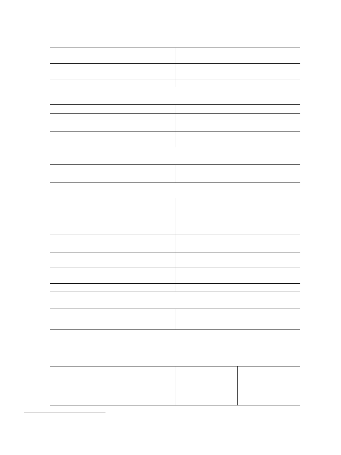
Technical Data
11.10 Directional Overcurrent Protection, Phases
Times
Operate time with time delay = 0 ms
Extension of the operate time during operation with
transformer inrush-current detection
Dropout time Approx. 20 ms + OOT
Frequency Operating Range
0.9 ≤ f/f
≤ 1.1 According to specified tolerances
rated
10 Hz ≤ f < 0.9 f
1.1 f
< f ≤ 80 Hz
rated
f < 10 Hz
f > 80 Hz
Tolerances
Currents, method of measurement = fundamental
component
Currents, method of measurement = RMS value
(33 % harmonics, in relation to fundamental component)
Up to 30th harmonic 1 % of the setting value or 5 mA (I
Up to 50th harmonic, f
Up to 50th harmonic, f
Operate time for 2 ≤ I/threshold value I ≤ 20 5 % of the reference (calculated) value
Dropout time for I/threshold value I ≤ 0.90 5 % of the reference (calculated) value
Direction-determination angle error 1°
rated
Approx. 37 ms + OOT 62 at 50 Hz
Approx. 22 ms + OOT at 60 Hz
Approx. 10 ms
Slightly expanded tolerances
Active
1 % of the setting value or 5 mA (I
or 25 mA (I
or 25 mA (I
= 50 Hz 3 % of the setting value or 20 mA (I
rated
or 100 mA (I
= 60 Hz 4 % of the setting value or 20 mA (I
rated
or 100 mA (I
= 5 A), (f
rated
= 5 A), (f
rated
rated
rated
= 5 A), (f
= 5 A), (f
rated
rated
rated
rated
+2 % current tolerance or 10 ms
+2 % current tolerance or 10 ms
± 10 %)
± 10 %)
± 10 %)
± 10 %)
rated
rated
rated
rated
= 1 A)
= 1 A)
= 1 A)
= 1 A)
Influencing Variables for Thresholds
Transient excess pickup in method of measurement =
< 5 %
fundamental component, for τ > 100 ms (with
complete unbalance)
11.10.3
Stage with User-Defined Characteristic Curve
Setting Values
Rotation angle of the reference voltage
Directional mode Forward
-180° to +180° Increments of 1°
–
Reverse
Method of measurement Fundamental component
–
RMS value
62
OOT (Output Operating Time): additional delay of the output medium used, for example 5 ms with fast relays
1146 SIPROTEC 5, High-Voltage Bay Controller, Manual
C53000-G5040-C015-A, Edition 05.2018
Page 52
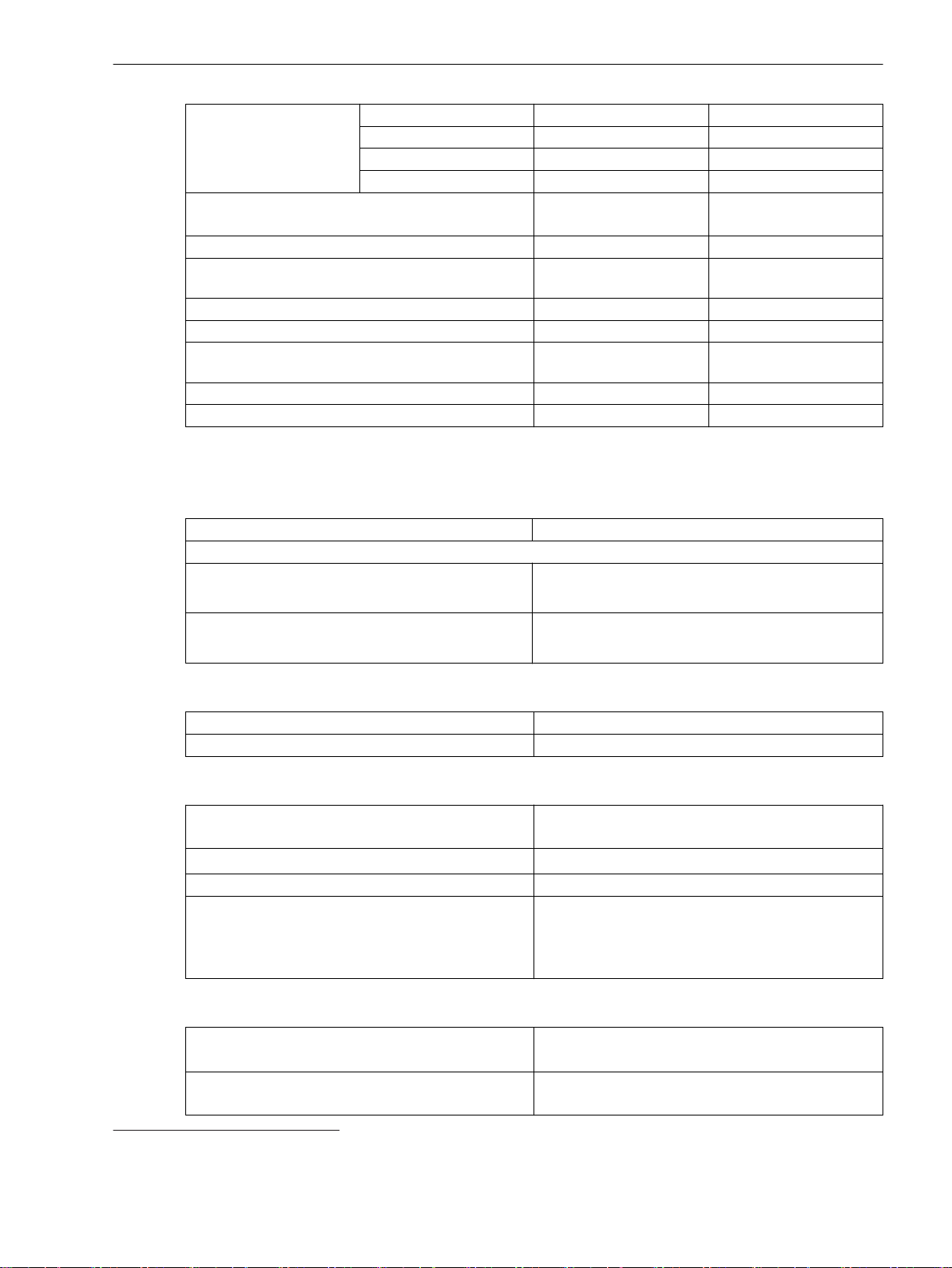
Technical Data
11.10 Directional Overcurrent Protection, Phases
Dropout
Threshold value
63
1 A @ 50 and 100 Irated 0.030 A to 35.000 A Increments of 0.001 A
5 A @ 50 and 100 Irated 0.15 A to 175.00 A Increments of 0.01 A
1 A @ 1.6 Irated 0.001 A to 1.600 A Increments of 0.001 A
5 A @ 1.6 Irated 0.005 A to 8.000 A Increments of 0.001 A
Dropout Disk emulation
-
Instantaneous
Time multiplier 0.05 to 15.00 Increments of 0.01
Number of value pairs for the operate characteristic
2 to 30 Increments of 1
curve
X values of the operate curve 1.00 p.u. to 66.67 p.u. Increments of 0.01 p.u.
Y values of the operate curve 0.00 s to 999.00 s Increments of 0.01 s
Number of value pairs for the dropout characteristic
2 to 30 Increments of 1
curve
X values of the dropout characteristic curve 0.05 p.u. to 0.95 p.u. Increments of 0.01 p.u.
Y values of the dropout characteristic curve 0.00 s to 999.00 s Increments of 0.01 s
The greater dropout differential (= | pickup value – dropout value |) of the following 2 criteria
applies:
Dropout 95 % of 1.1 ⋅ threshold value
Minimum absolute dropout differential
Protection-class current transformer 15 mA sec. (I
75 mA sec. (I
Instrument current transformer 0.5 mA sec. (I
2.5 mA sec. (I
= 1 A) or
rated
= 5 A)
rated
rated
rated
= 1 A) or
= 5 A)
Reset of the Integration Timer
Instantaneous
With dropout
Disk emulation Approx. < 0.90 ⋅ threshold value
Direction Determination
Type
With healthy voltages
With voltage memory 2 s
Forward range V
ref,rot
±88°
Dropout differential forward/reverse range 1°
Directional sensitivity Unlimited for 1-phase and 2-phase short circuits
Dynamically unlimited, stationary for 3-phase short
circuits
Approx. 13 V phase-to-phase
Times
Operate time with time delay = 0 ms
Approx. 37 ms + OOT 64 at 50 Hz
Approx. 22 ms + OOT at 60 Hz
Extension of the operate time during operation with
Approx. 10 ms
transformer inrush-current detection
63
If you have selected the method of measurement = RMS value, do not set the threshold value under 0.1 l
64
OOT (Output Operating Time): additional delay of the output medium used, for example 5 ms with fast relays
rated,sec
.
SIPROTEC 5, High-Voltage Bay Controller, Manual 1147
C53000-G5040-C015-A, Edition 05.2018
Page 53
Technical Data
11.10 Directional Overcurrent Protection, Phases
Dropout time Approx. 20 ms + OOT
Frequency Operating Range
Tolerances
0.9 ≤ f/f
10 Hz ≤ f < 0.9 f
1.1 f
f < 10 Hz
≤ 1.1 According to specified tolerances
rated
Slightly expanded tolerances
< f ≤ 80 Hz
rated
rated
Active
f > 80 Hz
Currents, method of measurement = fundamental
component
1 % of the setting value or 5 mA (I
or 25 mA (I
= 5 A), (f
rated
rated
± 10 %)
rated
Currents, method of measurement = RMS value
(33 % harmonics, in relation to fundamental component)
Up to 30th harmonic 1 % of the setting value or 5 mA (I
Up to 50th harmonic, f
Up to 50th harmonic, f
or 25 mA (I
= 50 Hz 3 % of the setting value or 20 mA (I
rated
or 100 mA (I
= 60 Hz 4 % of the setting value or 20 mA (I
rated
or 100 mA (I
= 5 A), (f
rated
rated
rated
= 5 A), (f
= 5 A), (f
rated
rated
rated
rated
± 10 %)
rated
± 10 %)
rated
± 10 %)
Operate time for 2 ≤ I/threshold value I≤ 20 5 % of the reference (calculated) value
+2 % current tolerance or 10 ms
Dropout time for I/threshold value I ≤ 0.90 5 % of the reference (calculated) value
+2 % current tolerance or 10 ms
Direction-determination angle error 1°
= 1 A)
= 1 A)
= 1 A)
= 1 A)
Influencing Variables for Thresholds
Transient excess pickup in method of measurement =
fundamental component, for τ > 100 ms (with
complete unbalance)
< 5 %
1148 SIPROTEC 5, High-Voltage Bay Controller, Manual
C53000-G5040-C015-A, Edition 05.2018
Page 54
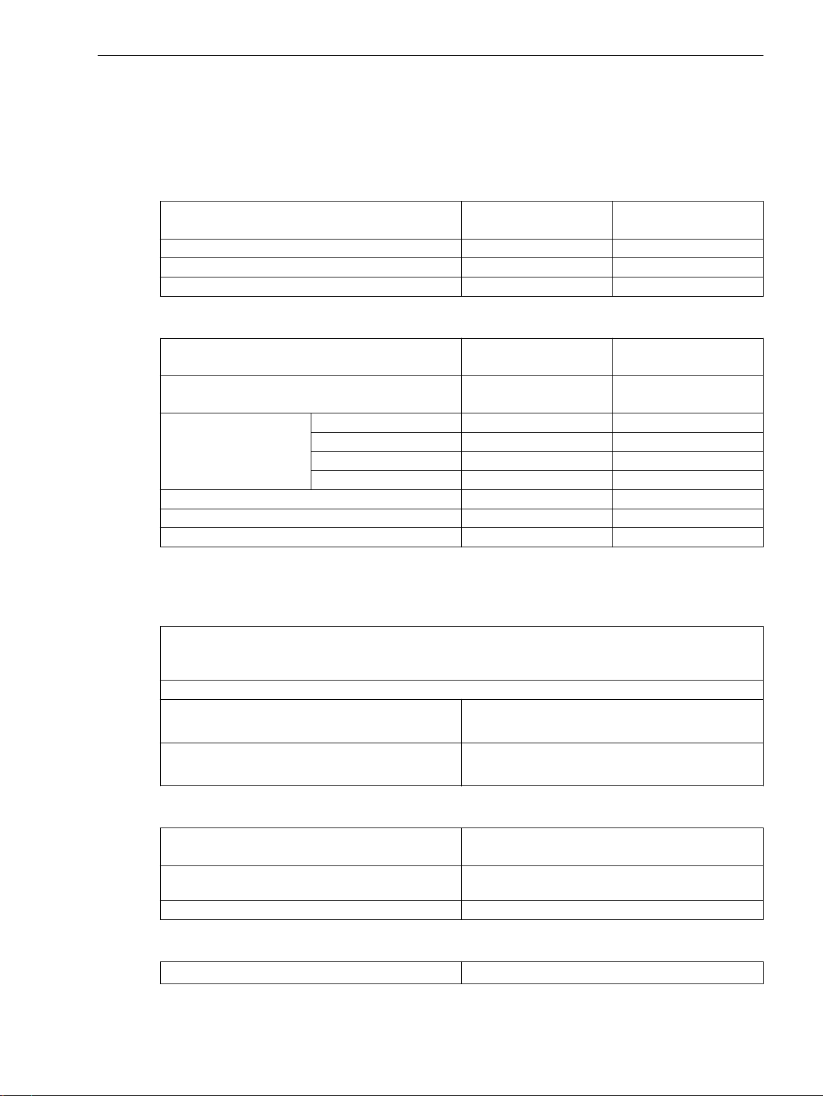
Technical Data
11.11 Directional Overcurrent Protection, Ground
11.11
11.11.1
Directional Overcurrent Protection, Ground
Stage with Definite-Time Characteristic Curve
Setting Values for the Function Direction Determination
Method for direction determination Zero sequence
Minimum V0 or V2 threshold 0.150 V to 20.000 V 0.001 V
Rotation angle of the reference voltage -180° to 180° 1°
Forward range 0° to 180° 1°
Setting Values
Direction mode Forward
Method of measurement Fundamental component
Threshold value 1 A @ 50 and 100 Irated 0.030 A to 35.000 A Increments of 0.001 A
5 A @ 50 and 100 Irated 0.15 A to 175.00 A Increments of 0.01 A
1 A @ 1.6 Irated 0.001 A to 1.600 A Increments of 0.001 A
5 A @ 1.6 Irated 0.005 A to 8.000 A Increments of 0.001 A
Dropout ratio 0.90 to 0.99 Increments of 0.01
Operate delay 0.00 s to 60.00 s Increments of 0.01 s
Dropout delay 0.00 s to 60.00 s Increments of 0.01 s
–
Negative sequence
–
Reverse
–
RMS value
Dropout
The greater dropout differential (= | pickup value – dropout value |) of the following 2 criteria
applies:
Dropout differential derived from the parameter
If this parameter is not available, a dropout ratio of 95 % applies for overcurrent and of 105 % for undercurrent functionality.
Minimum absolute dropout differential
Protection-class current transformer 15 mA sec. (I
Instrument current transformer 0.5 mA sec. (I
Times
The maximum pickup time with operate delay = 0 ms
Extension of the operate time during operation with
inrush-current detection
Dropout time Approx. 20 ms + OOT
Frequency Operating Range
0.9 ≤ f/f
≤ 1.1 According to specified tolerances
rated
Dropout ratio
= 1 A) or
rated
75 mA sec. (I
2.5 mA sec. (I
rated
rated
rated
= 5 A)
= 1 A) or
= 5 A)
Approx. 30 ms + OOT at 50 Hz
Approx. 25 ms + OOT at 60 Hz
Approx. 10 ms
SIPROTEC 5, High-Voltage Bay Controller, Manual 1149
C53000-G5040-C015-A, Edition 05.2018
Page 55
Technical Data
11.11 Directional Overcurrent Protection, Ground
10 Hz ≤ f < 0.9 f
1.1 f
< f ≤ 80 Hz
rated
rated
f < 10 Hz
f > 80 Hz
Tolerances
Currents, method of measurement = fundamental
component
Currents, method of measurement = RMS value
(33 % part of harmonic, referring to fundamental component)
Up to 30th harmonic 1 % of the setting value or 5 mA (I
Up to 50th harmonic, f
Up to 50th harmonic, f
rated
rated
Time delays 1 % of the setting value or 10 ms
Direction-determination angle error 1º
Influencing Variables for Thresholds
Slightly expanded tolerances
Active with reduced sensitivity
1 % of the setting value or 5 mA (I
or 25 mA (I
or 25 mA (I
= 5 A)
rated
= 5 A), (f
rated
rated
± 10 %)
= 50 Hz 3 % of the setting value or 20 mA (I
or 100 mA (I
= 5 A), (f
rated
rated
± 10 %)
= 60 Hz 4 % of the setting value or 20 mA (I
or 100 mA (I
= 5 A), (f
rated
rated
± 10 %)
rated
rated
rated
rated
= 1 A)
= 1 A)
= 1 A)
= 1 A)
Transient excess pickup in method of measurement =
fundamental component, for τ > 100 ms (with
complete unbalance)
11.11.2
Stage with Inverse-Time Characteristic Curve
Setting Values for the Function Direction Determination
Method for direction determination
Minimum V0 or V2 threshold 0.150 V to 20.000 V 0.001 V
Rotation angle of the reference voltage -180° to 180° 1°
Forward range 0° to 180° 1°
Setting Values
Direction mode
Method of measurement Fundamental component
Threshold value 1 A @ 50 and 100 Irated 0.030 A to 35.000 A Increments of 0.001 A
5 A @ 50 and 100 Irated 0.15 A to 175.00 A Increments of 0.01 A
1 A @ 1.6 Irated 0.001 A to 1.600 A Increments of 0.001 A
5 A @ 1.6 Irated 0.005 A to 8.000 A Increments of 0.001 A
Type of characteristic curve Characteristic curves according to IEC and ANSI
Dropout Disk emulation
Time multiplier 0.00 to 15.00 Increments of 0.01
< 5 %
Zero sequence
Negative sequence
Forward
Reverse
RMS value
Instantaneous
–
–
–
–
1150 SIPROTEC 5, High-Voltage Bay Controller, Manual
C53000-G5040-C015-A, Edition 05.2018
Page 56
Minimum time of the curve 0.00 s to 1.00 s Increments of 0.01 s
Additional time delay 0.00 s to 60.00 s Increments of 0.01 s
Dropout
The greater dropout differential (= | pickup value – dropout value |) of the following 2 criteria
applies:
Dropout 95 % of 1.1 ⋅ threshold value
Minimum absolute dropout differential
Protection-class current transformer 15 mA sec. (I
75 mA sec. (I
Instrument current transformer 0.5 mA sec. (I
2.5 mA sec. (I
Reset of the Integration Timer
Instantaneous With dropout
Disk emulation Approx. < 0.90 ⋅ threshold value
Operate Curves and Dropout-Time Characteristic Curves according to IEC
Technical Data
11.11 Directional Overcurrent Protection, Ground
= 1 A) or
rated
= 5 A)
rated
= 1 A) or
rated
= 5 A)
rated
Normal inverse: type A Refer to the respective figure of the technical data for
Very inverse: type B
Extremely inverse: type C
the non-dir-OC-ground function 11.9.2 Stage with
Inverse-Time Characteristic Curve
Long-time inverse: type B
Operate Curves and Dropout-Time Characteristic Curves according to ANSI/IEEE
Inverse: type C
Short inverse
Long inverse
Refer to the respective figure of the technical data for
the non-dir-OC-ground function 11.9.2 Stage with
Inverse-Time Characteristic Curve
Moderately inverse
Very inverse
Extremely inverse
Definite inverse
Times
The maximum pickup time with operate delay = 0 ms
Approx. 30 ms + OOT at 50 Hz
Approx. 25 ms + OOT at 60 Hz
Extension of the operate time during operation with
Approx. 10 ms
inrush-current detection
Dropout time Approx. 20 ms + OOT
Frequency Operating Range
0.9 ≤ f/f
10 Hz ≤ f < 0.9 f
1.1 f
f < 10 Hz
≤ 1.1 According to specified tolerances
rated
Slightly expanded tolerances
< f ≤ 80 Hz
rated
rated
Active with reduced sensitivity
f > 80 Hz
SIPROTEC 5, High-Voltage Bay Controller, Manual 1151
C53000-G5040-C015-A, Edition 05.2018
Page 57
Technical Data
11.11 Directional Overcurrent Protection, Ground
Tolerances
Currents, method of measurement = fundamental
component
Currents, method of measurement = RMS value
(33 % part of harmonic, referring to fundamental component)
Up to 30th harmonic 1 % of the setting value or 5 mA (I
Up to 50th harmonic, f
Up to 50th harmonic, f
rated
rated
Operate time for 2 ≤ I/I threshold value ≤ 20 5 % of the reference (calculated) value
Dropout time for I/I threshold value ≤ 0.90 5 % of the reference (calculated) value
Direction-determination angle error 1º
Influencing Variables for Thresholds
Transient excess pickup in method of measurement =
fundamental component, for τ > 100 ms (with
complete unbalance)
1 % of the setting value or 5 mA (I
or 25 mA (I
or 25 mA (I
= 5 A)
rated
= 5 A), (f
rated
rated
± 10 %)
= 50 Hz 3 % of the setting value or 20 mA (I
or 100 mA (I
= 5 A), (f
rated
rated
± 10 %)
= 60 Hz 4 % of the setting value or 20 mA (I
or 100 mA (I
= 5 A), (f
rated
rated
± 10 %)
+ 2 % current tolerance or 30 ms
+ 2 % current tolerance or 30 ms
< 5 %
rated
rated
rated
rated
= 1 A)
= 1 A)
= 1 A)
= 1 A)
11.11.3
Stage with Inverse-Time Overcurrent Protection with Logarithmic-Inverse Characteristic Curve
Setting Values for the Function Direction Determination
Method for direction determination
Minimum V0 or V2 threshold 0.150 V to 20.000 V 0.001 V
Rotation angle of the reference voltage -180° to 180° 1°
Forward range 0° to 180° 1°
Setting Values
Direction mode
Method of measurement Fundamental component
Threshold value 1 A @ 50 and 100 Irated 0.030 A to 35.000 A Increments of 0.001 A
5 A @ 50 and 100 Irated 0.15 A to 175.00 A Increments of 0.01 A
1 A @ 1.6 Irated 0.001 A to 1.600 A Increments of 0.001 A
5 A @ 1.6 Irated 0.005 A to 8.000 A Increments of 0.001 A
Characteristic curve: see Figure 11-13
Threshold value multiplier 1.00 to 4.00 Increments of 0.01
Time multiplier 0.000 s to 60.000 s Increments of 0.001 s
Minimum time of the characteristic curve 0.000 s to 60.000 s Increments of 0.001 s
Maximum time of the characteristic curve 0.000 s to 60.000 s Increments of 0.001 s
Zero sequence
Negative sequence
Forward
Reverse
RMS value
–
–
–
1152 SIPROTEC 5, High-Voltage Bay Controller, Manual
C53000-G5040-C015-A, Edition 05.2018
Page 58
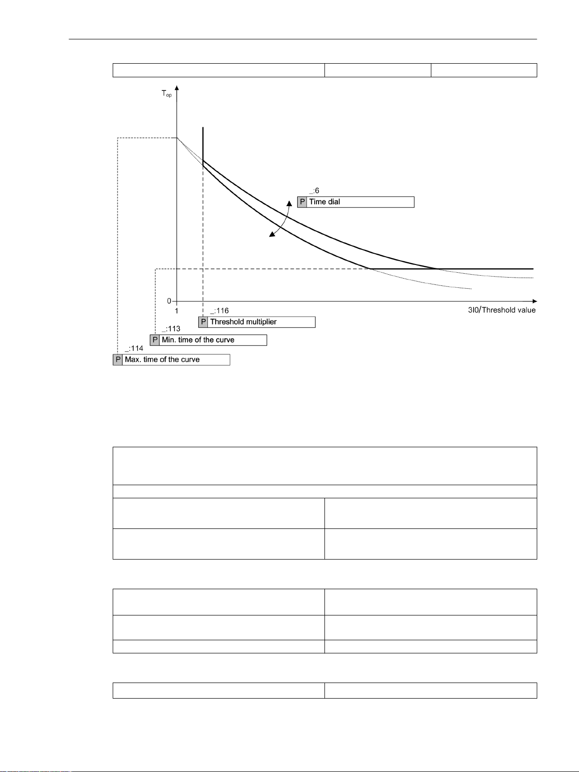
Technical Data
11.11 Directional Overcurrent Protection, Ground
Additional time delay 0.000 s to 60.000 s Increments of 0.001 s
Dropout
Times
[dwloginv-300913, 3, en_US]
Figure 11-13
Operate Curve of Logarithmic Inverse-Time Characteristic
The greater dropout differential (= | pickup value – dropout value |) of the following 2 criteria
applies:
Dropout differential derived from the parameter
Dropout ratio
If this parameter is not available, a dropout ratio of 95 % applies for overcurrent and of 105 % for undercurrent functionality.
Minimum absolute dropout differential
Protection-class current transformer 15 mA sec. (I
75 mA sec. (I
Instrument current transformer 0.5 mA sec. (I
2.5 mA sec. (I
The maximum pickup time with operate delay = 0 ms
Approx. 30 ms + OOT at 50 Hz
= 1 A) or
rated
= 5 A)
rated
rated
rated
= 1 A) or
= 5 A)
Approx. 25 ms + OOT at 60 Hz
Extension of the operate time during operation with
Approx. 10 ms
inrush-current detection
Dropout time Approx. 20 ms + OOT
Frequency Operating Range
0.9 ≤ f/f
SIPROTEC 5, High-Voltage Bay Controller, Manual 1153
C53000-G5040-C015-A, Edition 05.2018
≤ 1.1 According to specified tolerances
rated
Page 59
Technical Data
11.11 Directional Overcurrent Protection, Ground
Tolerances
10 Hz ≤ f < 0.9 f
1.1 f
< f ≤ 80 Hz
rated
f < 10 Hz
rated
Slightly expanded tolerances
Active with reduced sensitivity
f > 80 Hz
Currents, method of measurement = fundamental
component
1 % of the setting value or 5 mA (I
or 25 mA (I
rated
= 5 A)
Currents, method of measurement = RMS value
(33 % part of harmonic, referring to fundamental component)
Up to 30th harmonic 1 % of the setting value or 5 mA (I
Up to 50th harmonic, f
Up to 50th harmonic, f
= 50 Hz 3 % of the setting value or 20 mA (I
rated
= 60 Hz 4 % of the setting value or 20 mA (I
rated
Inverse-time operate time to logarithmic inverse-time
characteristic
Inverse-time dropout time to logarithmic inverse-time
characteristic
or 25 mA (I
or 100 mA (I
or 100 mA (I
5 % of the reference (calculated) value
+ 2 % current tolerance or 30 ms
5 % of the reference (calculated) value
+ 2 % current tolerance or 30 ms
= 5 A), (f
rated
rated
rated
= 5 A), (f
= 5 A), (f
rated
rated
rated
± 10 %)
± 10 %)
± 10 %)
Direction-determination angle error 1º
rated
rated
rated
rated
= 1 A)
= 1 A)
= 1 A)
= 1 A)
Influencing Variables for Thresholds
Transient excess pickup in method of measurement =
fundamental component, for τ > 100 ms (with
complete unbalance)
11.11.4
Stage with Knee-Point Characteristic Curve
Setting Values for the Function Direction Determination
Method for direction determination
Minimum V0 or V2 threshold 0.150 V to 20.000 V 0.001 V
Rotation angle of the reference voltage -180° to 180° 1°
Forward range 0° to 180° 1°
Setting Values
Direction mode
Method of measurement Fundamental component
Threshold value 1 A @ 50 and 100 Irated 0.030 A to 35.000 A Increments of 0.001 A
5 A @ 50 and 100 Irated 0.15 A to 175.00 A Increments of 0.01 A
1 A @ 1.6 Irated 0.001 A to 1.600 A Increments of 0.001 A
5 A @ 1.6 Irated 0.005 A to 8.000 A Increments of 0.001 A
< 5 %
Zero sequence
Negative sequence
Forward
Reverse
RMS value
–
–
–
1154 SIPROTEC 5, High-Voltage Bay Controller, Manual
C53000-G5040-C015-A, Edition 05.2018
Page 60
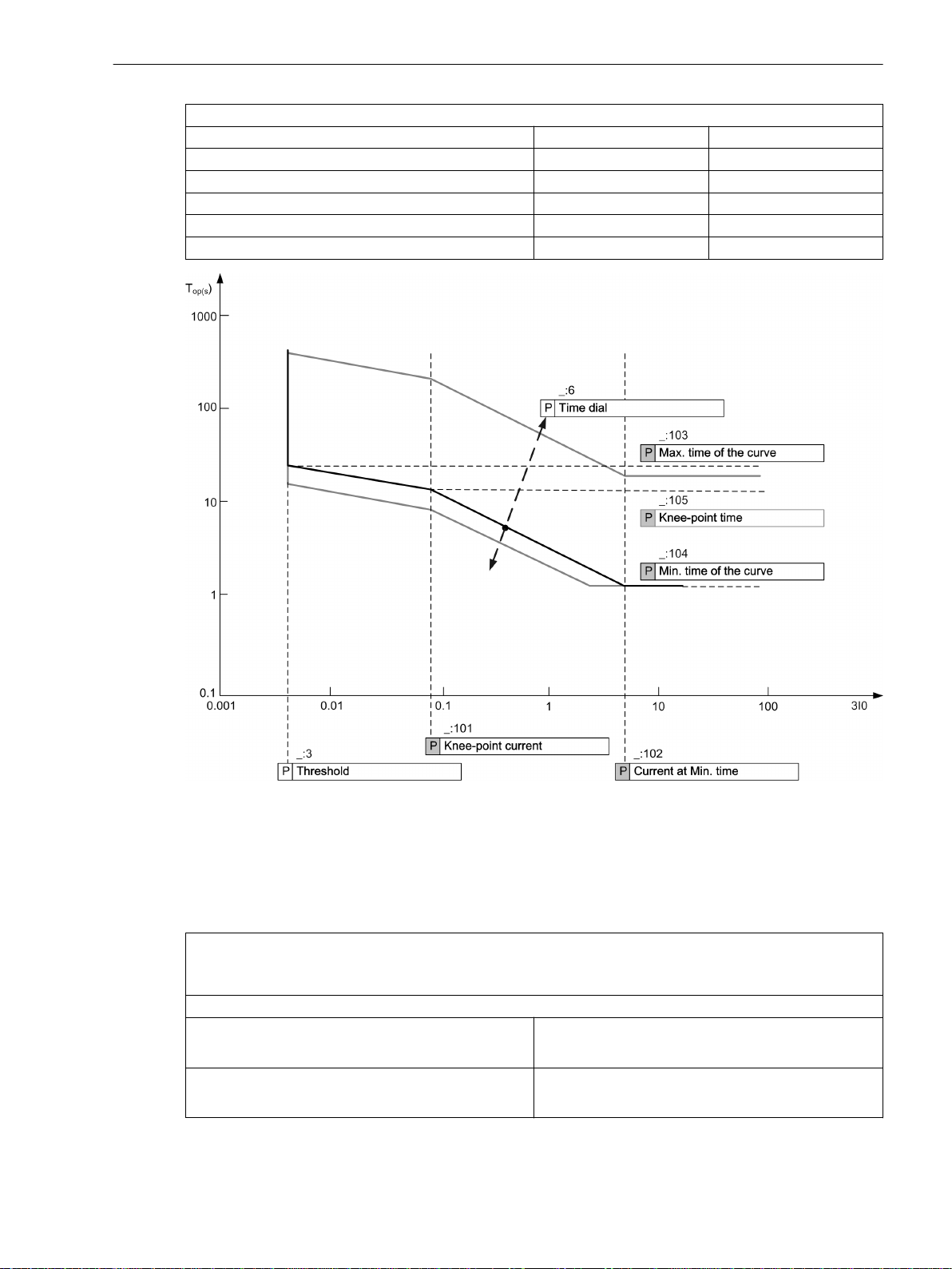
Technical Data
11.11 Directional Overcurrent Protection, Ground
Characteristic curve: see Figure 11-14
Minimum time of the characteristic curve 0.00 s to 30.00 s Increments of 0.01 s
Knee-point time of the curve 0.00 s to 100.00 s Increments of 0.01 s
Maximum time of the characteristic curve 0.00 s to 200.00 s Increments of 0.01 s
Knee-point value 0.030 A to 35.000 A Increments of 0.001 A
Current at minimum time of the curve 0.030 A to 35.000 A Increments of 0.001 A
Time multiplier 0.05 to 1.50 Increments of 0.01
[dwdrloinkn-171013, 1, en_US]
Figure 11-14
Operate Curve of the Logarithmic Inverse Time with Knee-Point Characteristic (In the Example
of Threshold = 0.004 A)
Dropout
The greater dropout differential (= | pickup value – dropout value |) of the following 2 criteria
applies:
Dropout differential derived from the parameter
Dropout ratio
If this parameter is not available, a dropout ratio of 95 % applies for overcurrent and of 105 % for undercurrent functionality.
Minimum absolute dropout differential
Protection-class current transformer 15 mA sec. (I
75 mA sec. (I
Instrument current transformer 0.5 mA sec. (I
2.5 mA sec. (I
SIPROTEC 5, High-Voltage Bay Controller, Manual 1155
C53000-G5040-C015-A, Edition 05.2018
= 1 A) or
rated
= 5 A)
rated
rated
rated
= 1 A) or
= 5 A)
Page 61
Technical Data
11.11 Directional Overcurrent Protection, Ground
Times
The maximum pickup time with operate delay = 0 ms Approx. 30 ms + OOT at 50 Hz
Extension of the operate time during operation with
inrush-current detection
Dropout time Approx. 20 ms + OOT
Frequency Operating Range
Approx. 25 ms + OOT at 60 Hz
Approx. 10 ms
Tolerances
0.9 ≤ f/f
10 Hz ≤ f < 0.9 f
1.1 f
f < 10 Hz
≤ 1.1 According to specified tolerances
rated
Slightly expanded tolerances
< f ≤ 80 Hz
rated
rated
Active with reduced sensitivity
f > 80 Hz
Currents, method of measurement = fundamental
component
1 % of the setting value or 5 mA (I
or 25 mA (I
rated
= 5 A)
Currents, method of measurement = RMS value
(33 % part of harmonic, referring to fundamental component)
Up to 30th harmonic 1 % of the setting value or 5 mA (I
Up to 50th harmonic, f
Up to 50th harmonic, f
= 50 Hz 3 % of the setting value or 20 mA (I
rated
= 60 Hz 4 % of the setting value or 20 mA (I
rated
Inverse-time operate time to logarithmic inverse time
with knee-point characteristic
Inverse-time dropout time to logarithmic inverse time
with knee-point characteristic
or 25 mA (I
or 100 mA (I
or 100 mA (I
5 % of the reference (calculated) value
+ 2 % current tolerance or 30 ms
5 % of the reference (calculated) value
+ 2 % current tolerance or 30 ms
= 5 A), (f
rated
rated
rated
= 5 A), (f
= 5 A), (f
rated
rated
rated
± 10 %)
± 10 %)
± 10 %)
Direction-determination angle error 1º
rated
rated
rated
rated
= 1 A)
= 1 A)
= 1 A)
= 1 A)
Influencing Variables for Thresholds
Transient excess pickup in method of measurement =
< 5 %
fundamental component, for τ > 100 ms (with
complete unbalance)
11.11.5
Stage with User-Defined Characteristic Curve
Setting Values for the Function Direction Determination
Method for direction determination
Zero sequence
–
Negative sequence
Minimum V0 or V2 threshold 0.150 V to 20.000 V 0.001 V
Rotation angle of the reference voltage -180° to 180° 1°
Forward range 0° to 180° 1°
1156 SIPROTEC 5, High-Voltage Bay Controller, Manual
C53000-G5040-C015-A, Edition 05.2018
Page 62
Setting Values
Technical Data
11.11 Directional Overcurrent Protection, Ground
Dropout
Direction mode Forward
–
Reverse
Method of measurement Fundamental component
–
RMS value
Threshold value 1 A @ 50 and 100 Irated 0.030 A to 35.000 A Increments of 0.001 A
5 A @ 50 and 100 Irated 0.15 A to 175.00 A Increments of 0.01 A
1 A @ 1.6 Irated 0.001 A to 1.600 A Increments of 0.001 A
5 A @ 1.6 Irated 0.005 A to 8.000 A Increments of 0.001 A
Dropout Disk emulation
–
Instantaneous
Time multiplier 0.05 to 15.00 Increments of 0.01
X values of the operate curve 1.00 p. u. to 66.67 p. u. Increments of 0.01 p. u.
Y values of the operate curve 0.00 s to 999.00 s Increments of 0.01 s
Number of value pairs for the dropout characteristic
2 to 30 Increments of 1
curve
X values of the dropout characteristic curve 0.05 p. u. to 0.95 p. u. Increments of 0.01 p. u.
Y values of the dropout characteristic curve 0.00 s to 999.00 s Increments of 0.01 s
The greater dropout differential (= | pickup value – dropout value |) of the following 2 criteria
applies:
Dropout
95 % of 1.1 ⋅ threshold value
Minimum absolute dropout differential
Protection-class current transformer 15 mA sec. (I
75 mA sec. (I
Instrument current transformer 0.5 mA sec. (I
2.5 mA sec. (I
= 1 A) or
rated
= 5 A)
rated
rated
rated
= 1 A) or
= 5 A)
Reset of the Integration Timer
Instantaneous
With dropout
Disk emulation Approx. < 0.90 ⋅ threshold value
Times
The maximum pickup time with operate delay = 0 ms
Approx. 30 ms + OOT at 50 Hz
Approx. 25 ms + OOT at 60 Hz
Extension of the operate time during operation with
Approx. 10 ms
inrush-current detection
Dropout time Approx. 20 ms + OOT
Frequency Operating Range
0.9 ≤ f/f
10 Hz ≤ f < 0.9 f
1.1 f
f < 10 Hz
≤ 1.1 According to specified tolerances
rated
Slightly expanded tolerances
< f ≤ 80 Hz
rated
rated
Active with reduced sensitivity
f > 80 Hz
SIPROTEC 5, High-Voltage Bay Controller, Manual 1157
C53000-G5040-C015-A, Edition 05.2018
Page 63
Technical Data
11.11 Directional Overcurrent Protection, Ground
Tolerances
Currents, method of measurement = fundamental
component
Currents, method of measurement = RMS value
(33 % part of harmonic, referring to fundamental component)
Up to 30th harmonic 1 % of the setting value or 5 mA (I
Up to 50th harmonic, f
Up to 50th harmonic, f
rated
rated
Operate time for 2 ≤ I/I threshold value ≤ 20 5 % of the reference (calculated) value
Dropout time for I/I threshold value ≤ 0.90 5 % of the reference (calculated) value
Direction-determination angle error 1º
Influencing Variables for Thresholds
Transient excess pickup in method of measurement =
fundamental component, for τ > 100 ms (with
complete unbalance)
1 % of the setting value or 5 mA (I
or 25 mA (I
or 25 mA (I
= 5 A)
rated
= 5 A), (f
rated
rated
± 10 %)
= 50 Hz 3 % of the setting value or 20 mA (I
or 100 mA (I
= 5 A), (f
rated
rated
± 10 %)
= 60 Hz 4 % of the setting value or 20 mA (I
or 100 mA (I
= 5 A), (f
rated
rated
± 10 %)
+ 2 % current tolerance or 30 ms
+ 2 % current tolerance or 30 ms
< 5 %
rated
rated
rated
rated
= 1 A)
= 1 A)
= 1 A)
= 1 A)
1158 SIPROTEC 5, High-Voltage Bay Controller, Manual
C53000-G5040-C015-A, Edition 05.2018
Page 64
Technical Data
11.12 Inrush-Current Detection
11.12
Inrush-Current Detection
Setting Values
Operating limit I
Content 2nd harmonic 10 % to 45 % Increments of 1 %
Duration of the crossblock function 0.03 s to 200.00 s Increments of 0.01 s
Times
Pre-arcing times Approx. 29 ms
Dropout Ratios
Harmonic: I
Dropout
The greater dropout differential (= | pickup value – dropout value |) of the following 2 criteria
applies:
Dropout differential derived from the parameter
If this parameter is not available, a dropout ratio of 95 % applies for overcurrent and of 105 % for undercurrent functionality.
Minimum absolute dropout differential
Protection-class current transformer 15 mA sec. (I
Instrument current transformer 0.5 mA sec. (I
max
2nd harm/I1st harm
0.030 A to 35.000 A
at I
= 1 A
rated
0.15 A to 175.00 A
at I
= 5 A
rated
0.95
Dropout ratio
75 mA sec. (I
2.5 mA sec. (I
= 1 A) or
rated
= 5 A)
rated
rated
rated
Increments of 0.001 A
Increments of 0.01 A
= 1 A) or
= 5 A)
Frequency Operating Range
0.9 ≤ f/f
10 Hz ≤ f < 0.9 f
1.1 f
f < 10 Hz
≤ 1.1 According to specified tolerances
rated
Slightly expanded tolerances
< f ≤ 80 Hz
rated
rated
Inactive
f > 80 Hz
Tolerances
Current measurement I
Harmonic: I
2nd harm/I1st harm
max
1 % of the setting value or 5 mA
1 % of the setting value with setting values
of I
2nd harm/I1st harm
Time delays 1 % of the setting value or 10 ms
SIPROTEC 5, High-Voltage Bay Controller, Manual 1159
C53000-G5040-C015-A, Edition 05.2018
Page 65
Technical Data
11.13 Instantaneous High-Current Tripping
11.13
Instantaneous High-Current Tripping
Setting Values
Threshold value 1 A @ 100 Irated 0.030 A to 35.000 A Increments of 0.001 A
Dropout ratio 0.50 to 0.90 Increments of 0.01
Dropout
The greater dropout differential (= | pickup value – dropout value |) of the following 2 criteria
applies:
Dropout differential derived from the parameter Dropout ratio
If this parameter is not available, a dropout ratio of 95 % applies for overcurrent and of 105 % for undercurrent functionality.
Minimum absolute dropout differential
Protection-class current transformer 15 mA sec. (I
Instrument current transformer 0.5 mA sec. (I
5 A @ 100 Irated 0.15 A to 175.00 A Increments of 0.01 A
1 A @ 50 Irated 0.030 A to 35.000 A Increments of 0.001 A
5 A @ 50 Irated 0.15 A to 175.00 A Increments of 0.01 A
1 A @ 1.6 Irated 0.001 A to 1.600 A Increments of 0.001 A
5 A @ 1.6 Irated 0.005 A to 8.000 A Increments of 0.001 A
= 1 A) or
rated
75 mA sec. (I
2.5 mA sec. (I
rated
rated
rated
= 5 A)
= 1 A) or
= 5 A)
Times
Tolerances
Operate time for current > 2·√2·threshold value
Response tolerance, current
Approx. 8 ms + OOT
5 % of setting value or 10 mA
at I
= 1 A
rated
65
5 % of setting value or 50 mA
at I
= 5 A
rated
Time delays 1 % of the setting value or 10 ms
65
OOT (Output Operating Time) Additional delay of the output medium used, see Chap. 11.1.4 Relay Outputs
1160 SIPROTEC 5, High-Voltage Bay Controller, Manual
C53000-G5040-C015-A, Edition 05.2018
Page 66
Technical Data
11.14 Stage with Definite-Time Characteristic Curve
11.14
Stage with Definite-Time Characteristic Curve
Setting Values
Method of measurement Fundamental component
Threshold value
Dropout ratio (fixed) 0.95 –
Time delay 0.00 s to 60.00 s Increments of 0.01 s
Dropout
The greater dropout differential (= | pickup value – dropout value |) of the following 2 criteria
applies:
Dropout differential derived from the parameter Dropout ratio
If this parameter is not available, a dropout ratio of 95 % applies for overcurrent and of 105 % for undercurrent functionality.
Minimum absolute dropout differential
Protection-class current transformer 15 mA sec. (I
Instrument current transformer 0.5 mA sec. (I
–
RMS value
66
For I
For I
= 1 A 0.010 A to 35.000 A Increments of 0.001 A
rated
= 5 A 0.05 A to 175.00 A Increments of 0.01 A
rated
= 1 A) or
rated
75 mA sec. (I
2.5 mA sec. (I
rated
rated
rated
= 5 A)
= 1 A) or
= 5 A)
Times
Operate time with time delay = 0 ms
Extension of the operate time during operation with
transformer inrush-current detection
Dropout time Approx. 20 ms + OOT at 50 Hz
Frequency Operating Range
0.9 ≤ f/f
≤ 1.1 According to specified tolerances
rated
10 Hz ≤ f < 0.9 f
1.1 f
< f ≤ 80 Hz
rated
f < 10 Hz
f > 80 Hz
Tolerances
Currents, method of measurement = fundamental
component
rated
Approx. 15 ms + OOT67 at 50 Hz
Approx. 14 ms + OOT at 60 Hz
Approx. 10 ms
Approx. 17 ms + OOT at 60 Hz
Slightly expanded tolerances
Active
1 % of the setting value or 5 mA (I
or 25 mA (I
= 5 A), (f
rated
rated
± 10 %)
rated
= 1 A)
66
If you have selected the method of measurement = RMS value, do not set the threshold value under 0.1 l
67
OOT (Output Operating Time): additional delay of the output medium used, see Chapter 11.1.4 Relay Outputs
SIPROTEC 5, High-Voltage Bay Controller, Manual 1161
C53000-G5040-C015-A, Edition 05.2018
rated,sec
.
Page 67
Technical Data
11.14 Stage with Definite-Time Characteristic Curve
Currents, method of measurement = RMS value
(33 % harmonics, in relation to fundamental component)
Up to 30th harmonic 1 % of the setting value or 5 mA (I
Up to 50th harmonic, f
Up to 50th harmonic, f
= 50 Hz 3 % of the setting value or 20 mA (I
rated
= 60 Hz 4 % of the setting value or 20 mA (I
rated
Time delays 1 % of the setting value or 10 ms
Influencing Variables for Thresholds
or 25 mA (I
or 100 mA (I
or 100 mA (I
= 5 A), (f
rated
rated
rated
= 5 A), (f
= 5 A), (f
rated
rated
rated
± 10 %)
± 10 %)
± 10 %)
rated
rated
rated
= 1 A)
= 1 A)
= 1 A)
Transient excess pickup in method of measurement =
fundamental component, for τ > 100 ms (with
complete unbalance)
< 5 %
1162 SIPROTEC 5, High-Voltage Bay Controller, Manual
C53000-G5040-C015-A, Edition 05.2018
Page 68
Technical Data
11.15 Stage with Inverse-Time Characteristic Curve
11.15
Stage with Inverse-Time Characteristic Curve
Setting Values
Method of measurement Fundamental component
Threshold value
Dropout Disk emulation
Time multiplier 0.05 to 15.00 Increments of 0.01
Dropout
The greater dropout differential (= | pickup value – dropout value |) of the following 2 criteria
applies:
Dropout 95 % of 1.1 ⋅ threshold value
Minimum absolute dropout differential
Protection-class current transformer 15 mA sec. (I
Instrument current transformer 0.5 mA sec. (I
–
RMS value
68
For I
For I
= 1 A 0.010 A to 35.000 A Increments of 0.001 A
rated
= 5 A 0.05 A to 175.00 A Increments of 0.01 A
rated
–
Instantaneous
= 1 A) or
rated
75 mA sec. (I
2.5 mA sec. (I
rated
rated
rated
= 5 A)
= 1 A) or
= 5 A)
Reset of the Integration Timer
Instantaneous
With dropout
Disk emulation Approx. < 0.90 ⋅ threshold value
Operate Curves and Dropout Characteristic Curves According to IEC
Extension of the operate time during operation with
Approx. 10 ms
transformer inrush-current detection
The operate curves and dropout characteristic curves according to IEC can be found in the Technical Data
chapter under Inverse-Time Overcurrent Protection.
Operate Curves and Dropout Characteristic Curves According to ANSI/IEEE
The operate curves and dropout characteristic curves according to ANSI/IEEE can be found in the Technical
Data chapter under Inverse-Time Overcurrent Protection.
Frequency Operating Range
0.9 ≤ f/f
10 Hz ≤ f < 0.9 f
1.1 f
f < 10 Hz
≤ 1.1 According to specified tolerances
rated
Slightly expanded tolerances
< f ≤ 80 Hz
rated
rated
Active
f > 80 Hz
68
If you have selected the method of measurement = RMS value, do not set the threshold value under 0.1 l
SIPROTEC 5, High-Voltage Bay Controller, Manual 1163
C53000-G5040-C015-A, Edition 05.2018
rated,sec
.
Page 69
Technical Data
11.15 Stage with Inverse-Time Characteristic Curve
Tolerances
Currents, method of measurement = fundamental
component
Currents, method of measurement = RMS value
(33 % harmonics, in relation to fundamental component)
Up to 30th harmonic 1 % of the setting value or 5 mA (I
Up to 50th harmonic, f
Up to 50th harmonic, f
rated
rated
Operate time for 2 ≤ I/I threshold value ≤ 20 5 % of the reference (calculated) value
Dropout time for I/I threshold value ≤ 0.90 5 % of the reference (calculated) value
Influencing Variables for Thresholds
Transient excess pickup in method of measurement =
fundamental component, for τ > 100 ms (with
complete unbalance)
1 % of the setting value or 5 mA (I
or 25 mA (I
or 25 mA (I
= 5 A), (f
rated
= 5 A), (f
rated
rated
rated
± 10 %)
± 10 %)
= 50 Hz 3 % of the setting value or 20 mA (I
or 100 mA (I
= 5 A), (f
rated
rated
± 10 %)
= 60 Hz 4 % of the setting value or 20 mA (I
or 100 mA (I
= 5 A), (f
rated
rated
± 10 %)
+2 % current tolerance or 30 ms
+2 % current tolerance or 30 ms
< 5 %
rated
rated
rated
rated
= 1 A)
= 1 A)
= 1 A)
= 1 A)
1164 SIPROTEC 5, High-Voltage Bay Controller, Manual
C53000-G5040-C015-A, Edition 05.2018
Page 70
Technical Data
11.16 Voltage-Dependent Overcurrent Protection, Phases
11.16
Voltage-Dependent Overcurrent Protection, Phases
Setting Values for All Stage Types
Method of measurement Fundamental component
Overcurrent threshold
value
For I
For I
= 1 A 0.030 A to 35.000 A Increments of 0.001 A
rated
= 5 A 0.15 A to 175.00 A Increments of 0.01 A
rated
Time delay 0.10 s to 60.00 s Increments of 0.01 s
Setting Values for Inverse-Time Overcurrent Protection Stages
Method of measurement Fundamental component
Dropout ratio of undervoltage
Undervoltage threshold value
69
69
Dropout Disk emulation
Time multiplier 0.05 to 15.00 Increments of 0.01
Setting Values for Definite-Time Overcurrent Protection Stages
Seal-in voltage
Phase-to-phase voltage 0.300 V to 175.000 V Increments of 0.001 V
Negative-sequence voltage V2 0.300 V to 200.000 V Increments of 0.001 V
Time delay 0.00 s to 60.00 s Increments of 0.01 s
Duration of V-seal-in time 0.10 s to 60.00 s Increments of 0.01 s
–
RMS value
–
RMS value
1.01 to 1.20 Increments of 0.01
0.300 V to 175.000 V Increments of 0.001 V
–
Instantaneous
0.300 V to 175.000 V Increments of 0.001 V
Dropout for Inverse-Time Overcurrent Protection Stages
The greater dropout differential (= | pickup value – dropout value |) of the following 2 criteria
applies:
Dropout
Current 95 % of 1.1 ⋅ threshold value
Voltage
69
105 % of threshold value
Minimum absolute dropout differential
Protection-class current transformer 15 mA sec. (I
75 mA sec. (I
Instrument current transformer 0.5 mA sec. (I
2.5 mA sec. (I
Voltage transformer
69
150 mV sec.
Reset of the Integration Timer for Inverse-Time Overcurrent Protection Stages
Instantaneous
With dropout
Disk emulation Approx. < 0.90 ⋅ threshold value
= 1 A) or
rated
= 5 A)
rated
rated
rated
= 1 A) or
= 5 A)
69
The value is for the inverse-time overcurrent voltage-released stage.
SIPROTEC 5, High-Voltage Bay Controller, Manual 1165
C53000-G5040-C015-A, Edition 05.2018
Page 71
Technical Data
11.16 Voltage-Dependent Overcurrent Protection, Phases
Dropout for Definite-Time Overcurrent Protection Stages
Dropout differential derived from the parameter Dropout ratio
If this parameter is not available, a dropout ratio of 95 % applies for overcurrent/overvoltage and of 105 % for
undervoltage functionality.
Minimum absolute dropout differential
Protection-class current transformer 15 mA sec. (I
75 mA sec. (I
Instrument current transformer 0.5 mA sec. (I
2.5 mA sec. (I
Voltage transformer 150 mV sec.
Operate Curves and Dropout Characteristic Curves According to IEC
= 1 A) or
rated
= 5 A)
rated
rated
rated
= 1 A) or
= 5 A)
Extension of the operate time during operation with
Approx. 10 ms
inrush-current detection
The operate curves and dropout characteristic curves according to IEC can be found in the chapter Technical
Data under Inverse-Time Overcurrent Protection.
Operate Curves and Dropout Characteristic Curves According to ANSI/IEEE
The operate curves and dropout characteristic curves according to IEC can be found in the chapter Technical
Data under Inverse-Time Overcurrent Protection.
Frequency Operating Range
0.9 ≤ f/f
10 Hz ≤ f < 0.9 f
1.1 f
f < 10 Hz
≤ 1.1 According to specified tolerances
rated
Slightly expanded tolerances
< f ≤ 80 Hz
rated
rated
Inactive
f > 80 Hz
Tolerances
Currents, method of measurement = fundamental
component
1 % of the setting value or 5 mA (I
or 25 mA (I
Currents, method of measurement = RMS value
(33 % part of harmonic in relation to fundamental component)
Up to 30th harmonic 1 % of the setting value or 5 mA (I
or 25 mA (I
Up to 50th harmonic, f
= 50 Hz 3 % of the setting value or 20 mA (I
rated
or 100 mA (I
Up to 50th harmonic, f
= 60 Hz 4 % of the setting value or 20 mA (I
rated
or 100 mA (I
Voltage 0.5 % of the setting value or 0.05 V
Operate time for 2 ≤ I/I threshold value ≤ 20 5 % of the reference (calculated) value
+ 2 % current tolerance or 30 ms
Dropout time for I/I threshold value ≤ 0.90 5 % of the reference (calculated) value
+ 2 % current tolerance or 30 ms
Time delays 1 % of the setting value or 10 ms
= 5 A), (f
rated
= 5 A), (f
rated
rated
rated
= 5 A), (f
= 5 A), (f
rated
rated
rated
rated
± 10 %)
± 10 %)
± 10 %)
± 10 %)
rated
rated
rated
rated
= 1 A)
= 1 A)
= 1 A)
= 1 A)
1166 SIPROTEC 5, High-Voltage Bay Controller, Manual
C53000-G5040-C015-A, Edition 05.2018
Page 72

Influencing Variables for Thresholds
Technical Data
11.16 Voltage-Dependent Overcurrent Protection, Phases
Transient excess pickup in method of measurement =
fundamental component, for τ > 100 ms (with
complete unbalance)
< 5 %
SIPROTEC 5, High-Voltage Bay Controller, Manual 1167
C53000-G5040-C015-A, Edition 05.2018
Page 73
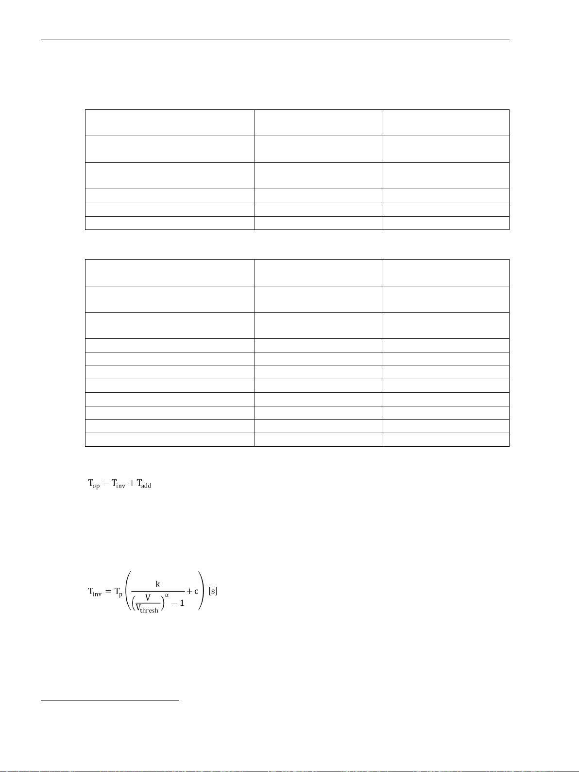
Technical Data
11.17 Overvoltage Protection with 3-Phase Voltage
11.17
Overvoltage Protection with 3-Phase Voltage
Setting Values for Stage Type Definite-Time Overvoltage Protection
Measured value Phase-to-phase
Phase-to-ground
Method of measurement Fundamental component
RMS value
Pickup mode 1 out of 3
3 out of 3
Pickup value
70
0.300 V to 340.000 V Increments of 0.001 V
Time delay 0.00 s to 300.00 s Increments of 0.01 s
Dropout ratio 0.90 to 0.99 Increments of 0.01
Setting Values for Stage Type Inverse-Time Overvoltage Protection
Measured value Phase-to-phase
Phase-to-ground
Method of measurement Fundamental component
RMS value
Pickup mode 1 out of 3
3 out of 3
Pickup value 0.300 V to 340.000 V Increments of 0.001 V
Pickup factor 1.00 to 1.20 Increments of 0.01
Characteristic constant k 0.00 to 300.00 Increments of 0.01
Characteristic constant α 0.010 to 5.000 Increments of 0.001
Characteristic constant c 0.000 to 5.000 Increments of 0.001
Time multiplier 0.05 to 15.00 Increments of 0.01
Additional time delay 0.00 s to 60.00 s Increments of 0.01 s
Reset time 0.00 s to 60.00 s Increments of 0.01 s
Operate Curve for Stage Type Inverse-Time Overvoltage Protection
Where
T
op
T
inv
T
add
Operate delay
Inverse-time delay
Additional time delay (parameter Additional time delay)
Where
T
inv
T
p
Inverse-time delay
Time multiplier (parameter Time dial)
V Measured voltage
70
If you have selected the method of measurement = RMS value, do not set the threshold value under 10 V.
1168 SIPROTEC 5, High-Voltage Bay Controller, Manual
C53000-G5040-C015-A, Edition 05.2018
Page 74
Technical Data
11.17 Overvoltage Protection with 3-Phase Voltage
V
thresh
Threshold value (parameter Threshold)
k Curve constant k (parameter Charact. constant k)
α Curve constant α (parameter Charact. constant α)
c Curve constant c (parameter Charact. constant c)
Dropout
The greater dropout differential (= | pickup value – dropout value |) of the following 2 criteria
applies:
Dropout differential derived from the parameter Dropout ratio
If this parameter is not available, a dropout ratio of 95 % applies for the overvoltage and of 105 % for the
undervoltage functionality.
Minimum absolute dropout differential 150 mV sec.
Times
Operate time with time delay = 0 ms
Dropout time Approx. 20 ms + OOT
Frequency Operating Range
0.9 ≤ f/f
≤ 1.1 According to specified tolerances
rated
10 Hz ≤ f < 0.9 f
1.1 f
< f ≤ 80 Hz
rated
f < 10 Hz
f > 80 Hz
rated
Approx. 25 ms + OOT71 at 50 Hz
Approx. 22 ms + OOT at 60 Hz
Slightly expanded tolerances
Active
Tolerances for Stage Type Definite-Time Overvoltage Protection
Voltages
Time delays 1 % of the setting value or 10 ms
Tolerances for Stage Type Inverse-Time Overvoltage Protection
Voltages
Operate time for
1.2 ≤ V/V threshold value ≤ 20
Reset time delay 1 % of the setting value or 10 ms
0.5 % of the setting value or 0.05 V
0.5 % of the setting value or 0.05 V
5 % of the setting value or 30 ms
71
OOT (Output Operating Time): additional delay of the output medium used, see chapter 11.1.4 Relay Outputs
SIPROTEC 5, High-Voltage Bay Controller, Manual 1169
C53000-G5040-C015-A, Edition 05.2018
Page 75
Technical Data
11.18 Overvoltage Protection with Positive-Sequence Voltage
11.18
Overvoltage Protection with Positive-Sequence Voltage
Setting Values
Pickup value 0.300 V to 200.000 V Increments of 0.001 V
Time delay 0.00 s to 60.00 s Increments of 0.01 s
Dropout ratio 0.90 to 0.99 Increments of 0.01
Dropout
The greater dropout differential (= | pickup value – dropout value |) of the following 2 criteria
applies:
Dropout differential derived from the parameter Dropout ratio
If this parameter is not available, a dropout ratio of 95 % applies for the overvoltage and of 105 % for the
undervoltage functionality.
Minimum absolute dropout differential 150 mV sec.
Times
Operate time with time delay = 0 ms
Dropout time Approx. 20 ms + OOT
Frequency Operating Range
Approx. 25 ms + OOT72 at 50 Hz
Approx. 22 ms + OOT at 60 Hz
Tolerances
0.9 ≤ f/f
10 Hz ≤ f < 0.9 f
1.1 f
f < 10 Hz
≤ 1.1 According to specified tolerances
rated
Slightly expanded tolerances
< f ≤ 80 Hz
rated
rated
Active
f > 80 Hz
Voltages
0.5 % of the setting value or 0.05 V
Time delays 1 % of the setting value or 10 ms
72
OOT (Output Operating Time): additional delay of the output medium used, see Chapter 11.1.4 Relay Outputs
1170 SIPROTEC 5, High-Voltage Bay Controller, Manual
C53000-G5040-C015-A, Edition 05.2018
Page 76
Technical Data
11.19 Overvoltage Protection with Any Voltage
11.19
Overvoltage Protection with Any Voltage
Setting Values
Measured value
Method of measurement Fundamental component
Pickup value
Time delay 0.00 s to 60.00 s Increments of 0.01 s
Dropout ratio 0.90 to 0.99 Increments of 0.01
Dropout
73
Measured phase-to-ground voltage V
Measured phase-to-ground voltage V
Measured phase-to-ground voltage V
Measured phase-to-phase voltage V
Measured phase-to-phase voltage V
Measured phase-to-phase voltage V
Measured phase-to-phase voltage V
Measured phase-to-phase voltage V
Measured phase-to-phase voltage V
A
B
C
AB
BC
CA
AB
BC
CA
Calculated voltage V0
RMS value
74
0.300 V to 340.000 V Increments of 0.001 V
The greater dropout differential (= | pickup value – dropout value |) of the following 2 criteria
applies:
Dropout differential derived from the parameter
If this parameter is not available, a dropout ratio of 95 % applies for the overvoltage and of 105 % for the
undervoltage functionality.
Minimum absolute dropout differential 150 mV sec.
Times
Operate time with time delay = 0 ms
Dropout time Approx. 20 ms + OOT
Frequency Operating Range
0.9 ≤ f/f
≤ 1.1 According to specified tolerances
rated
10 Hz ≤ f < 0.9 f
1.1 f
< f ≤ 80 Hz
rated
f < 10 Hz
f > 80 Hz
Tolerances
Voltages
rated
Dropout ratio
Approx. 25 ms + OOT75 at 50 Hz
Approx. 22 ms + OOT at 60 Hz
Slightly expanded tolerances
Active
0.5 % of the setting value or 0.05 V
73
If the function Overvoltage protection with any voltage is used in a 1-phase function group, the measured-value parameter is not
visible.
74
If you have selected the method of measurement = RMS value, do not set the threshold value under 10 V.
75
OOT (Output Operating Time): additional delay of the output medium used, see Chapter 11.1.4 Relay Outputs
SIPROTEC 5, High-Voltage Bay Controller, Manual 1171
C53000-G5040-C015-A, Edition 05.2018
Page 77

Technical Data
11.19 Overvoltage Protection with Any Voltage
Time delays 1 % of the setting value or 10 ms
1172 SIPROTEC 5, High-Voltage Bay Controller, Manual
C53000-G5040-C015-A, Edition 05.2018
Page 78
Technical Data
11.20 Undervoltage Protection with 3-Phase Voltage
11.20
Undervoltage Protection with 3-Phase Voltage
Setting Values for Stage Type Definite-Time Undervoltage Protection
Measured value Phase-to-phase
Phase-to-ground
Method of measurement Fundamental component
RMS value
Current-flow criterion On
Off
Threshold value I> 1 A @ 50 and 100 Irated 0.030 A to 10.000 A Increments of 0.001 A
5 A @ 50 and 100 Irated 0.15 A to 50.00 A Increments of 0.01 A
1 A @ 1.6 Irated 0.001 A to 1.600 A Increments of 0.001 A
5 A @ 1.6 Irated 0.005 A to 8.000 A Increments of 0.001 A
Threshold value
76
0.300 V to 175.000 V Increments of 0.001 V
Time delay 0.00 s to 60.00 s Increments of 0.01 s
Dropout ratio 1.01 to 1.20 Increments of 0.01
Setting Values for Stage Type Inverse-Time Undervoltage Protection
Measured value Phase-to-phase
Phase-to-ground
Method of measurement Fundamental component
RMS value
Current-flow criterion On
Off
Threshold value I> 1 A @ 50 and 100 Irated 0.030 A to 10.000 A Increments of 0.001 A
5 A @ 50 and 100 Irated 0.15 A to 50.00 A Increments of 0.01 A
1 A @ 1.6 Irated 0.001 A to 1.600 A Increments of 0.001 A
5 A @ 1.6 Irated 0.005 A to 8.000 A Increments of 0.001 A
Threshold 0.300 V to 175.000 V Increments of 0.001 V
Pickup factor 0.80 to 1.00 Increments of 0.01
Characteristic constant k 0.00 to 300.00 Increments of 0.01
Characteristic constant α 0.010 to 5.000 Increments of 0.001
Characteristic constant c 0.000 to 5.000 Increments of 0.001
Time multiplier 0.05 to 15.00 Increments of 0.01
Additional time delay 0.00 s to 60.00 s Increments of 0.01 s
Reset time 0.00 s to 60.00 s Increments of 0.01 s
Operate Curve
T
op=TInv+Tadd
Where:
T
op
T
Inv
T
add
76
If you have selected the Method of measurement = RMS value, do not set the threshold value under 10 V.
SIPROTEC 5, High-Voltage Bay Controller, Manual 1173
C53000-G5040-C015-A, Edition 05.2018
Operate delay
Inverse-time delay
Additional time delay (parameter Additional time delay)
Page 79
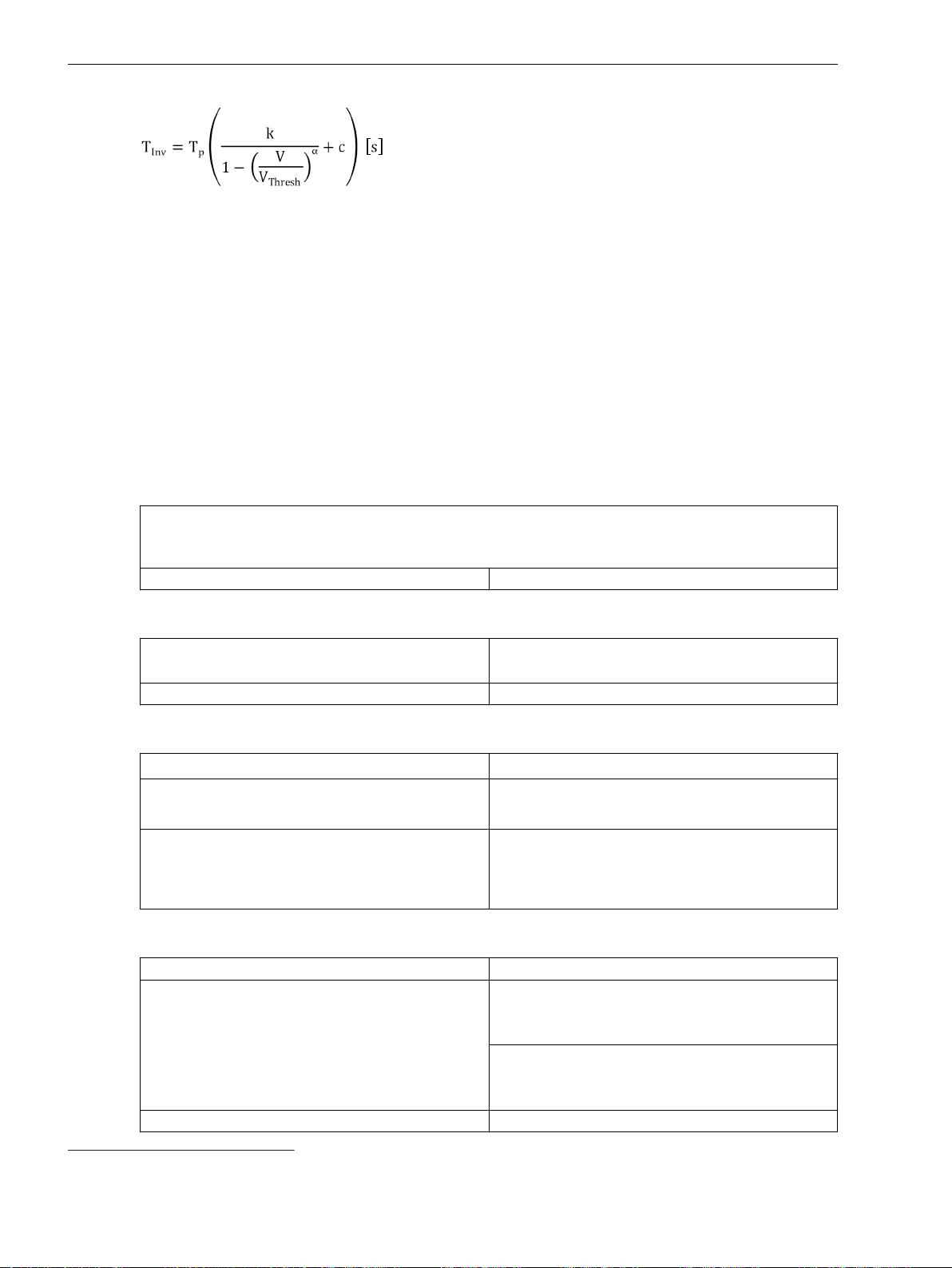
Technical Data
11.20 Undervoltage Protection with 3-Phase Voltage
[fo_UVP3ph_inverse, 2, en_US]
Where
T
Inv
T
p
Inverse-time delay
Time multiplier (parameter Time dial)
V Measured undervoltage
V
Thresh
Threshold value (parameter Threshold)
k Curve constant k (parameter Charact. constant k)
α Curve constant α (parameter Charact. constant α)
c Curve constant c (parameter Charact. constant c)
Dropout
The greater dropout differential (= | pickup value – dropout value |) of the following 2 criteria
applies:
Dropout differential derived from the parameter Dropout ratio
If this parameter is not available, a dropout ratio of 95 % applies for the overvoltage and of 105 % for the
undervoltage functionality.
Minimum absolute dropout differential 150 mV sec.
Times
Pickup time
Dropout time Approx. 20 ms + OOT
Frequency Operating Range
0.9 ≤ f/f
10 Hz ≤ f < 0.9 f
1.1 f
≤ 1.1 According to specified tolerances
rated
rated
< f ≤ 80 Hz
rated
f < 10 Hz
f > 80 Hz
Tolerances for Stage Type Definite-Time Undervoltage Protection
Voltages
Currents 1 % of the setting value or 5 mA (I
Time delays 1 % of the setting value or 10 ms
Approx. 25 ms + OOT77 at 50 Hz
Approx. 22 ms + OOT at 60 Hz
Slightly expanded tolerances
Inactive, maintained;
Dropout of the pickup induced by blocking or by
increasing the measurand beyond the dropout
threshold
0.5 % of the setting value or 0.05 V
= 1 A) or 25 mA
rated
(I
rated
= 5 A, f
± 10 %), valid for protection-class
rated
current transformers
1 % of the setting value or 0.1 mA (I
0.5 mA (I
rated
= 8 A, f
± 10 %), valid for instrument
rated
= 1.6 A) or
rated
transformers
77
OOT (Output Operating Time): additional delay of the output medium used, see Chapter 11.1.4 Relay Outputs
1174 SIPROTEC 5, High-Voltage Bay Controller, Manual
C53000-G5040-C015-A, Edition 05.2018
Page 80
Tolerances for Stage Type Inverse-Time Undervoltage Protection
Voltages 0.5 % of the setting value or 0.05 V
Currents 1 % of the setting value or 5 mA (I
Operate time for 0 < V/V
< 0.9 5 % of the setting value or 30 ms
Thresh
Reset time delay 1 % of the setting value or 10 ms
11.20 Undervoltage Protection with 3-Phase Voltage
(I
rated
= 5 A, f
± 10 %), valid for protection-class
rated
current transformers
1 % of the setting value or 0.1 mA (I
0.5 mA (I
rated
= 8 A, f
± 10 %), valid for instrument
rated
transformers
Technical Data
= 1 A) or 25 mA
rated
= 1.6 A) or
rated
SIPROTEC 5, High-Voltage Bay Controller, Manual 1175
C53000-G5040-C015-A, Edition 05.2018
Page 81
Technical Data
11.21 Undervoltage Protection with Any Voltage
11.21
Undervoltage Protection with Any Voltage
Setting Values
Measured value Measured phase-to-ground voltage V
Method of measurement Fundamental component
Threshold value
Time delay 0.00 s to 60.00 s Increments of 0.01 s
Dropout ratio 1.01 to 1.20 Increments of 0.01
Dropout
A
Measured phase-to-ground voltage V
Measured phase-to-ground voltage V
Measured phase-to-phase voltage V
Measured phase-to-phase voltage V
Measured phase-to-phase voltage V
Calculated phase-to-phase voltage V
Calculated phase-to-phase voltage V
Calculated phase-to-phase voltage V
B
C
AB
BC
CA
AB
BC
CA
Calculated voltage V0
RMS value
78
0.300 V to 340.000 V Increments of 0.001 V
The greater dropout differential (= | pickup value – dropout value |) of the following 2 criteria
applies:
Dropout differential derived from the parameter
If this parameter is not available, a dropout ratio of 95 % applies for the overvoltage and of 105 % for the
undervoltage functionality.
Minimum absolute dropout differential 150 mV sec.
Times
Operate time with time delay = 0 ms
Dropout time Approx. 20 ms + OOT
Frequency Operating Range
0.9 ≤ f/f
≤ 1.1 According to specified tolerances
rated
10 Hz ≤ f < 0.9 f
1.1 f
< f ≤ 80 Hz
rated
f < 10 Hz
f > 80 Hz
Tolerances
rated
Dropout ratio
Approx. 25 ms + OOT79 at 50 Hz
Approx. 22 ms + OOT at 60 Hz
Slightly expanded tolerances
Inactive, maintained;
Dropout of the pickup induced by blocking or by increasing the
measurand beyond the dropout threshold
Voltages
0.5 % of the setting value or 0.05 V
Time delays 1 % of the setting value or 10 ms
78
If you have selected the method of measurement = RMS value, do not set the threshold value under 10 V.
79
OOT (Output Operating Time): additional delay of the output medium used, see chapter 11.1.4 Relay Outputs
1176 SIPROTEC 5, High-Voltage Bay Controller, Manual
C53000-G5040-C015-A, Edition 05.2018
Page 82
Technical Data
11.22 Overfrequency Protection
11.22
Overfrequency Protection
Setting Values
Pickup values f> 40.00 Hz to 70.00 Hz Increments of 0.01 Hz
Dropout differential 20 mHz to 2 000 mHz Increments of 10 mHz
Time delay T 0.00 s to 600.00 s Increments of 0.01 s
Minimum voltage 3.000 V to 175.000 V Increments of 0.001 V
Times
Pickup times f> Angle difference method
Dropout times f> 60 ms to 80 ms
Dropout
Frequency Parameterizable dropout differential
Minimum voltage
The larger dropout differential (= | pickup value – dropout threshold |) of the following
2 criteria is used:
Dropout differential derived from Dropout ratio 105 % for the Minimum voltage parameter
Minimum absolute dropout differential 150 mV secondary
50 Hz
60 Hz
Filtering method
50 Hz
60 Hz
Approx. 70 ms + OOT
Approx. 60 ms + OOT
Approx. 79 ms + OOT
Approx. 65 ms + OOT
80
Operating Ranges
Voltage range
Frequency range Angle difference method 10 Hz to 80 Hz
Tolerances
Frequency f>
f
- 0.20 Hz < f < f
rated
f
- 3.0 Hz < f < f
rated
Time delay T(f>) 1 % of the setting value or 10 ms
Minimum voltage 1 % of the setting value or 0.5 V
5 V to 230 V (phase-phase)
Filtering method 25 Hz to 80 Hz
+ 0.20 Hz ± 5 mHz at V = V
rated
+ 3.0 Hz ± 10 mHz at V = V
rated
rated
rated
80
OOT (Output Operating Time): Additional delay of the output medium used, for example, 5 ms with fast relays, see chapter
11.1.4 Relay Outputs
SIPROTEC 5, High-Voltage Bay Controller, Manual 1177
C53000-G5040-C015-A, Edition 05.2018
Page 83
Technical Data
11.23 Underfrequency Protection
11.23
Underfrequency Protection
Setting Values
Pickup values f< 40.00 Hz to 70.00 Hz Increments of 0.01 Hz
Dropout differential 20 mHz to 2 000 mHz Increments of 10 mHz
Time delay T 0.00 s to 600.00 s Increments of 0.01 s
Minimum voltage 3.000 V to 175.000 V Increments of 0.001 V
Times
Pickup times f< Angle difference method
Dropout times f< 60 ms to 80 ms
Dropout
Frequency Parameterizable dropout differential
Minimum voltage
The larger dropout differential (= | pickup value – dropout threshold |) of the following
2 criteria is used:
Dropout differential derived from Dropout ratio 105 % for the Minimum voltage parameter
Minimum absolute dropout differential 150 mV secondary
50 Hz
60 Hz
Filtering method
50 Hz
60 Hz
Approx. 70 ms + OOT
Approx. 60 ms + OOT
Approx. 65 ms + OOT
Approx. 54 ms + OOT
81
Operating Ranges
Voltage range
Frequency range Angle difference method 10 Hz to 80 Hz
Tolerances
Frequency f<
f
- 0.20 Hz < f < f
rated
f
- 3.0 Hz < f < f
rated
Time delay T(f<) 1 % of the setting value or 10 ms
Minimum voltage 1 % of the setting value or 0.5 V
5 V to 230 V (phase-phase)
Filtering method 25 Hz to 80 Hz
+ 0.20 Hz ± 5 mHz at V = V
rated
+ 3.0 Hz ± 10 mHz at V = V
rated
rated
rated
81
OOT (Output Operating Time): Additional delay of the output medium used, for example, 5 ms with fast relays, see chapter
11.1.4 Relay Outputs
1178 SIPROTEC 5, High-Voltage Bay Controller, Manual
C53000-G5040-C015-A, Edition 05.2018
Page 84
Technical Data
11.24 Underfrequency Load Shedding
11.24
Underfrequency Load Shedding
Setting Values for the Function
Minimum voltage 0.300 p.u. to 0.900 p.u. Increments of 0.001 p.u.
Minimum current 0.020 p.u. to 0.200 p.u. Increments of 0.001 p.u.
Power angle -30° to 30° Increments of 1°
Positive power direction inv. to CT neu.pnt sett.
Threshold value for the df/dt-rising
rate or df/dt-falling rate
df/dt measuring window 2 periods to 5 periods Increments of 1 period
df/dt dropout differential 0.02 Hz/s to 0.99 Hz/s Increments of 0.10 Hz/s
f < stabilization counter 1 to 20 Increments of 1
Setting Values for the Stage
Pickup threshold 40.00 Hz to 70.00 Hz Increments of 0.01 Hz
Dropout differential 20 mHz to 2000 mHz Increments of 10 mHz
Time delay 0.00 s to 60.00 s Increments of 0.01 s
Times
Pickup times with stabilization counter = 6
Dropout time Approx. 80 ms + OOT at 50 Hz
acc. to CT neu.pnt sett.
0.1 Hz/s to 20.0 Hz/s Increments of 0.1 Hz/s
Approx. 85 ms + OOT82 at 50 Hz
Approx. 80 ms + OOT at 60 Hz
Approx. 75 ms + OOT at 60 Hz
Dropout
Tolerances
The greater dropout differential (= | pickup value – dropout value |) of the following 2 criteria
applies:
Dropout
Frequency 0.01 Hz
df/dt-rising rate and df/dt-falling rate 0.1 Hz/s
Voltage V1 105 % of the threshold value
Current I1 105 % of the threshold value at φ ≤ 0
95.23 % of the threshold value at φ > 0
Power angle 1°
Minimum absolute dropout differential
Protection-class current transformer 15 mA sec. (I
75 mA sec. (I
Instrument current transformer 0.5 mA sec. (I
2.5 mA sec. (I
= 1 A) or
rated
= 5 A)
rated
rated
rated
= 1 A) or
= 5 A)
Voltage transformer 150 mV sec.
Frequency f<
f
- 0.20 Hz < f < f
rated
+ 0.20 Hz ± 5 mHz at V = V
rated
rated
82
OOT (Output Operating Time): additional time delay of the output medium used, for example, 5 ms with fast relay
SIPROTEC 5, High-Voltage Bay Controller, Manual 1179
C53000-G5040-C015-A, Edition 05.2018
Page 85
Technical Data
11.24 Underfrequency Load Shedding
f
- 3.0 Hz < f < f
rated
rated
df/dt, measuring window > 3 periods Approx. 3 % or 0.06 Hz/s
df/dt, measuring window ≤ 3 periods Approx. 5 % or 0.06 Hz/s
Minimum voltage 0.5 % of the setting value or 0.05 V
Minimum current 1 % of the setting value or 5 mA (I
Power angle 1°
Time delays 1 % of the setting value or 10 ms
Frequency Operating Range
+ 3.0 Hz ± 10 mHz at V = V
(I
= 5 A), (f
rated
rated
rated
± 10 %)
= 1 A) or 25 mA
rated
0.9 ≤ f/f
≤ 1.1 According to specified tolerances
rated
10 Hz ≤ f < 0.9 f
1.1 f
< f ≤ 80 Hz
rated
f < 10 Hz
f > 80 Hz
rated
Slightly expanded tolerances
Active
1180 SIPROTEC 5, High-Voltage Bay Controller, Manual
C53000-G5040-C015-A, Edition 05.2018
Page 86
Technical Data
11.25 Rate of Frequency Change Protection
11.25
Rate of Frequency Change Protection
Setting Values for the Function
Minimum voltage 3.000 V to 175.000 V Increments of 0.001 V
Measuring window 2 periods to 5 periods Increments of 1 period
Setting Values for Stage Types
Threshold 0.100 Hz/s to 20.000 Hz/s Increments of 0.025 Hz/s
Dropout differential 0.02 Hz/s to 0.99 Hz/s Increments of 0.01 Hz/s
Operate delay 0.00 s to 60.00 s Increments of 0.01 s
Dropout
Frequency Parameterizable dropout differential
Minimum voltage
The larger dropout differential (= | pickup value – dropout threshold |) of the following
2 criteria is used:
Dropout differential derived from Dropout ratio 105 % for the Minimum voltage parameter
Minimum absolute dropout differential 150 mV secondary
Times
Pickup time
Dropout time Approx. 160 ms + OOT to 220 ms + OOT (depends on measuring
Approx. 160 ms + OOT83 to 220 ms + OOT (depends on measuring
window length)
at 50 Hz
Approx. 140 ms + OOT to 200 ms + OOT (depends on measuring
window length)
at 60 Hz
window length)
at 50 Hz
Approx. 140 ms + OOT to 200 ms + OOT (depends on measuring
window length)
at 60 Hz
Frequency Operating Range
0.9 ≤ f/f
10 Hz ≤ f < 0.9 f
1.1 f
f < 10 Hz
≤ 1.1 According to specified tolerances
rated
Slightly expanded tolerances
< f ≤ 80 Hz
rated
rated
Inactive
f > 80 Hz
Tolerances
Threshold,
Approx. 3 % or 0.060 Hz/s
measuring window > 3 periods
Threshold,
Approx. 5 % or 0.060 Hz/s
measuring window ≤ 3 periods
83
OOT (Output Operating Time): Additional delay of the output medium used, for example, 5 ms with fast relays, see chapter
11.1.4 Relay Outputs
SIPROTEC 5, High-Voltage Bay Controller, Manual 1181
C53000-G5040-C015-A, Edition 05.2018
Page 87

Technical Data
11.25 Rate of Frequency Change Protection
Minimum voltage 1 % of the setting value or 0.5 V
Time delays 1 % of the setting value or 10 ms
Functional Measured Value
Value Description
df/dt Calculated rate of frequency change
1182 SIPROTEC 5, High-Voltage Bay Controller, Manual
C53000-G5040-C015-A, Edition 05.2018
Page 88
Technical Data
11.26 Power Protection (P,Q), 3-Phase
11.26
Power Protection (P,Q), 3-Phase
Setting Values
Measured value Positive sequence power
Threshold value -200.0 % to +200.0 % Increments of 0.1
Tilt-power characteristic -89.0° to +89.0° Increments of 0.1°
Dropout delay time 0.00 s to 60.00 s Increments of 0.01 s
Time delay 0.00 s to 60.00 s Increments of 0.01 s
Dropout ratio Upper stage: 0.90 to 0.99
Times
Pickup times
Dropout times Approx. 55 ms + OOT at 50-Hz
Tolerances
Power of phase A
Power of phase B
Power of phase C
Lower stage: 1.01 to 1.10
Approx. 55 ms + OOT84 at 50 Hz
Approx. 45 ms + OOT at 60 Hz
Approx. 45 ms + OOT at 60 Hz
Increments of 0.01
Increments of 0.01
Power
Time delays 1 % of the setting value or 10 ms
Variables That Influence Pickup Values
Auxiliary DC voltage in the range 0.8 ≤ V
V
aux.,rated
≤ 1.15
Frequency in the range 0.95 ≤ f/f
Harmonics
- Up to 10 % of 3rd harmonics
- Up to 10 % of 5th harmonics
Frequency Operating Range
0.9 ≤ f/f
10 Hz < f < 0.9 f
1.1 f
≤ 1.1 According to specified tolerances
rated
rated
< f
rated
f ≤ 10 Hz Inactive
/
aux.
≤ 1.05 ≤ 1 %
rated
0.5 % S
(S
rated
± 3 % of setting value
rated
: rated apparent power)
≤ 1 %
≤ 1 %
≤ 1 %
Slightly expanded tolerances
84
OOT (Output Operating Time): additional delay of the output medium used, see Chapter 11.1.4 Relay Outputs
SIPROTEC 5, High-Voltage Bay Controller, Manual 1183
C53000-G5040-C015-A, Edition 05.2018
Page 89

Technical Data
11.27 Instantaneous Tripping at Switch onto Fault
11.27
Setting Values
Tolerances
Instantaneous Tripping at Switch onto Fault
Tripping delay 0.00 s to 60.00 s Increments of
Times < 1 % of the setting value or 10 ms
0.01 s
1184 SIPROTEC 5, High-Voltage Bay Controller, Manual
C53000-G5040-C015-A, Edition 05.2018
Page 90
i
i
Technical Data
11.28 Circuit-Breaker Failure Protection
11.28
Starting Conditions
Setting Values
Dropout
Circuit-Breaker Failure Protection
For circuit-breaker failure protection
Phase-current threshold
values
Sensitive threshold value 1 A @ 100 Irated 0.030 A to 35.000 A Increments of 0.001 A
Supervision time of release signal 0.00 s to 1.00 s Increments of 0.01 s
Time delays T1 0.000 s to 60.000 s Increments of 0.001 s
Time delays T2 0.050 s to 60.000 s Increments of 0.001 s
Monitoring times of the binary inputs 0.05 s to 60.00 s Increments of 0.01 s
The greater dropout differential (= | pickup threshold – dropout threshold |) of the following 2
criteria applies:
3-pole tripping internal or external
1 A @ 100 Irated 0.030 A to 35.000 A Increments of 0.001 A
5 A @ 100 Irated 0.15 A to 175.00 A Increments of 0.01 A
1 A @ 1.6 Irated 0.001 A to 1.600 A Increments of 0.001 A
5 A @ 1.6 Irated 0.005 A to 8.000 A Increments of 0.001 A
5 A @ 100 Irated 0.15 A to 175.00 A Increments of 0.01 A
1 A @ 1.6 Irated 0.001 A to 1.600 A Increments of 0.001 A
5 A @ 1.6 Irated 0.005 A to 8.000 A Increments of 0.001 A
85
Dropout differential
Minimum absolute dropout differential
Protection-class current transformer 15 mA sec. (I
Instrument current transformer 0.5 mA sec. (I
Circuit-Breaker Supervision
Position supervision via circuit-breaker auxiliary contacts
For 3-pole CB tripping 1 input each for make contact and break contact
NOTE
The circuit-breaker failure protection can also work without the circuit-breaker auxiliary contacts stated.
Auxiliary contacts are required for circuit-breaker failure protection in cases where the current flow is
absent or too low for tripping (for example with a transformer or a Buchholz protection).
Times
Pickup time, in the case of an internal start
Pickup time, in the case of an external start
Typical dropout time < 15 ms
Dropout time via circuit-breaker auxiliary contact
criterion
95 % of the pickup value
= 1 A) or
rated
75 mA sec. (I
2.5 mA sec. (I
< 1 ms
< 5 ms
< 5 ms
rated
rated
rated
= 5 A)
= 1 A) or
= 5 A)
85
Via binary inputs
SIPROTEC 5, High-Voltage Bay Controller, Manual 1185
C53000-G5040-C015-A, Edition 05.2018
Page 91
Technical Data
11.28 Circuit-Breaker Failure Protection
Frequency Operating Range
Tolerances
0.9 ≤ f/f
10 Hz ≤ f < 0.9 f
1.1 f
f < 10 Hz
≤ 1.1 According to specified tolerances
rated
Slightly expanded tolerances
< f ≤ 80 Hz
rated
rated
Active
f > 80 Hz
Threshold values, dropout thresholds 2 % of the setting value or 1 % of the rated current
Times 1 % of the setting value or 10 ms
1186 SIPROTEC 5, High-Voltage Bay Controller, Manual
C53000-G5040-C015-A, Edition 05.2018
Page 92
Technical Data
11.29 Negative-Sequence Protection with Definite-Time Characteristic Curve
11.29
Negative-Sequence Protection with Definite-Time Characteristic
Curve
Setting Values
Reference value for I2 (I
Pickup value 5.0 % to 999.9 % l2/l
Time Delay 0.00 s to 60.00 s Increments of 0.01 s
Release current
(minimum current
release)
Maximum phase
current (maximum
current limiting)
Times
Pickup times Approx. 35 ms + OOT
Dropout times Approx. 35 ms + OOT
Dropout Ratio
Pickup value
) Rated object current I
ref
Positive sequence current I
rated, obj.
ref
1
Increments of 0.1
1 A @ 50 and 100 Irated 0.030 A to 10.000 A Increments of 0.001 A
5 A @ 50 and 100 Irated 0.15 A to 50.00 A Increments of 0.01 A
1 A @ 50 and 100 Irated 0.030 A to 35.000 A Increments of 0.001 A
5 A @ 50 and 100 Irated 0.15 A to 175.00 A Increments of 0.01 A
Approx. 0.95 for I2/I
≥ 0.3
ref
Operating Ranges
Current range
Frequency range 10 Hz to 80 Hz
Tolerances
Pickup value
I2/I
rated, obj
I2/I
1
Time delays 1 % of the setting value or 10 ms
0.05 x I
≤ all phase currents ≤ setting value I
rated, obj
ph, max
Approx. 2 % of the setting value or 0.8 % absolute value (transformer
mismatching < 4)
Approx. 2 % of the setting value or 4 % absolute value (I1 > 50 mA (1 A)
or 250 mA (5 A))
SIPROTEC 5, High-Voltage Bay Controller, Manual 1187
C53000-G5040-C015-A, Edition 05.2018
Page 93
Technical Data
11.30 Stage with Inverse-Time Characteristic Curve
11.30
Stage with Inverse-Time Characteristic Curve
Setting Values
Reference value for I2 (I
Pickup value 5.0 % to 999.9 % l2/l
Dropout Disk emulation
Time multiplier 0.05 to 15.00 Increments of 0.01
Release current (minimum
current release)
Maximum phase current
(maximum current
limiting)
Dropout
The greater dropout differential (= | pickup value – dropout value |) of the following 2 criteria
applies:
•
•
) Rated object current I
ref
Positive-sequence current I
Instantaneous
1 A @ 50 and 100 Irated 0.030 A to 10.000 A Increments of 0.001 A
5 A @ 50 and 100 Irated 0.15 A to 50.00 A Increments of 0.01 A
1 A @ 1.6 Irated 0.001 A to 1.600 A Increments of 0.001 A
5 A @ 1.6 Irated 0.005 A to 8.000 A Increments of 0.001 A
1 A @ 50 and 100 Irated 0.030 A to 35.000 A Increments of 0.001 A
5 A @ 50 and 100 Irated 0.15 A to 175.00 A Increments of 0.01 A
1 A @ 1.6 Irated 0.001 A to 1.600 A Increments of 0.001 A
5 A @ 1.6 Irated 0.005 A to 8.000 A Increments of 0.001 A
Dropout differential derived from the parameter Dropout ratio
Dropout differential of 3 % of the object rated current
rated,obj.
ref
1
Increments of 0.1
Times
Pickup time
Dropout time Approx. 35 ms + OOT
Dropout Ratio
Disk emulation
Instantaneous Approx. 1.05 ⋅ threshold value
Operate and Dropout Characteristic Curves
You can select from the following operate and dropout characteristic curves:
Table 11-3
Standard Characteristic Curves to IEC
Normal inverse: type A See chapter 11.8.2 Stage with Inverse-Time Charac-
Very inverse: type B
Extremely inverse: type C See chapter 11.8.2 Stage with Inverse-Time Charac-
Long-time inverse: type B
Approx. 40 ms + OOT86 at 50 Hz
Approx. 35 ms + OOT at 60 Hz
Approx. 0.90 ⋅ threshold value
Approx. 0.95 ⋅ pickup value
teristic Curve, Figure 11-1
teristic Curve, Figure 11-2
86
OOT (Output Operating Time): additional delay of the output medium used, see chapter 11.1.4 Relay Outputs
1188 SIPROTEC 5, High-Voltage Bay Controller, Manual
C53000-G5040-C015-A, Edition 05.2018
Page 94
Table 11-4 Standard Characteristic Curves to ANSI
Inverse: type C See chapter 11.8.2 Stage with Inverse-Time Charac-
Short inverse
Long inverse See chapter 11.8.2 Stage with Inverse-Time Charac-
Moderately inverse
Very inverse See chapter 11.8.2 Stage with Inverse-Time Charac-
Extremely inverse
Definite inverse See chapter 11.8.2 Stage with Inverse-Time Charac-
Extension of the Operating Time
Technical Data
11.30 Stage with Inverse-Time Characteristic Curve
teristic Curve, Figure 11-3
teristic Curve, Figure 11-4
teristic Curve, Figure 11-5
teristic Curve, Figure 11-6
Extension of the operate time during operation with
transformer inrush-current detection
Current Operating Range
Current range At least one phase current ≥ setting value I
Frequency Operating Range
0.9 ≤ f/f
10 Hz ≤ 0.9 f
1.1 f
≤ 1.1 According to specified tolerances
rated
rated
< f ≤ 80 Hz
rated
f < 10 Hz
f > 80 Hz
Tolerances
Reference value = rated current
Pickup value Approx. 2 % of the setting value or
Operate time for 2 ≤ I/I threshold value ≤ 20 5 % of the setting value or
Dropout time for I/I threshold value ≤ 0.90 5 % of the setting value or
Reference value = pos. seq. current
Pickup value Approx. 2 % of the setting value
Operate time for 2 ≤ I/I threshold value ≤ 20 5 % of the reference (calculated) value
Dropout time for I/I threshold value ≤ 0.90 5 % of the reference (calculated) value
Approx. 10 ms
All phase currents ≤ setting value I
ph, max
Slightly expanded tolerances
Inactive
0.8 % of the absolute value
+ 2 % of the current tolerance or 30 ms
+ 2 % of the current tolerance or 30 ms
or 4 % of the absolute value
(I1 > 50 mA (I
= 1 A) or 250 mA (I
rated
rated
+ 2 % current tolerance or 30 ms
+ 2 % current tolerance or 30 ms
release
= 5 A))
SIPROTEC 5, High-Voltage Bay Controller, Manual 1189
C53000-G5040-C015-A, Edition 05.2018
Page 95
Technical Data
11.31 Thermal Overload Protection, 3-Phase – Advanced
11.31
Setting Value for the Function Block Filter
Setting Values/Increments for the Protection Stage
Thermal Overload Protection, 3-Phase – Advanced
h(0) -100.000 to 100.000 Increments of 0.001
h(1) -100.000 to 100.000 Increments of 0.001
h(2) -100.000 to 100.000 Increments of 0.001
h(3) -100.000 to 100.000 Increments of 0.001
h(4) -100.000 to 100.000 Increments of 0.001
Threshold current
warning
Threshold thermal warn. 50 % to 100 % Increments of 1 %
Dropout threshold operate 50 % to 99 % Increments of 1 %
Emerg. start T overtravel 0 s to 15 000 s Increments of 10 s
K-factor acc. to IEC 60225-8 0.10 to 4.00 Increments of 0.01
Thermal time constant 10 s to 60 000 s Increments of 1 s
Cooling time constant 10 s to 60 000 s Increments of 1 s
Imax thermal 1 A @ 50 and 100 Irated 0.030 A to 10.000 A Increments of 0.001 A
Imin cooling 1 A @ 50 and 100 Irated 0.000 A to 10.000 A Increments of 0.001 A
Temperature rise at Irated 40 K to 200 K Increments of 1 K
Default temperature -55°C to 55°C Increments of 1°C
Minimal temperature -55°C to 40°C Increments of 1°C
1 A @ 50 and 100 Irated 0.030 A to 35.000 A Increments of 0.001 A
5 A @ 50 and 100 Irated 0.15 A to 175.00 A Increments of 0.01 A
1 A @ 1.6 Irated 0.001 A to 1.600 A Increments of 0.001 A
5 A @ 1.6 Irated 0.005 A to 8.000 A Increments of 0.001 A
5 A @ 50 and 100 Irated 0.15 A to 50.00 A Increments of 0.01 A
1 A @ 1.6 Irated 0.001 A to 1.600 A Increments of 0.001 A
5 A @ 1.6 Irated 0.005 A to 8.000 A Increments of 0.001 A
5 A @ 50 and 100 Irated 0.00 A to 50.00 A Increments of 0.01 A
1 A @ 1.6 Irated 0.000 A to 1.600 A Increments of 0.001 A
5 A @ 1.6 Irated 0.000 A to 8.000 A Increments of 0.001 A
Dropout Ratios
Tripping threshold (fixed at 100 %)
Thermal warning threshold About 0.99 of the setting value
Current warning threshold About 0.95 of the setting value
Frequency Range of the Input Signals
The function captures input signals up to the 50th harmonic.
1190 SIPROTEC 5, High-Voltage Bay Controller, Manual
Dropout if value drops below operate indication
dropout threshold
C53000-G5040-C015-A, Edition 05.2018
Page 96
Tolerances
11.31 Thermal Overload Protection, 3-Phase – Advanced
No filter applied
(33 % harmonics, in relation to the fundamental component)
With reference to k ⋅ I
Up to 30th harmonic 2 % or 10 mA ( I
rated
or 50 mA ( I
rated
= 1 A)
rated
= 5 A),
2 % class acc. to IEC 60255-149
Up to 50th harmonic,
f
= 50 Hz
rated
4 % or 20 mA ( I
or 100 mA ( I
rated
= 1 A)
rated
= 5 A),
4 % class acc. to IEC 60255-149
Up to 50th harmonic,
f
= 60 Hz
rated
5 % or 25 mA ( I
or 125 mA ( I
rated
= 1 A)
rated
= 5 A),
5 % class acc. to IEC 60255-149
With the filter for compensation of the amplitude attenuation due to the anti-aliasing filter
(33 % harmonics, in relation to the fundamental component)
With reference to k ⋅ I
Up to 30th harmonic 2 % or 10 mA ( I
rated
or 50 mA ( I
rated
= 1 A)
rated
= 5 A),
2 % class acc. to IEC 60255-149
Up to 50th harmonic,
f
= 50 Hz
rated
3 % or 20 mA ( I
or 100 mA ( I
rated
= 1 A)
rated
= 5 A),
3 % class acc. to IEC 60255-149
Up to 50th harmonic,
f
= 60 Hz
rated
4 % or 20 mA ( I
or 100 mA ( I
rated
= 1 A)
rated
= 5 A),
4 % class acc. to IEC 60255-149
With the filter for gain of harmonics including compensation of the amplitude attenuation
Technical Data
87
(33 % harmonics, in relation to the fundamental component)
With reference to k ⋅ I
Up to 30th harmonic 2 % or 10 mA ( I
rated
or 50 mA ( I
rated
= 1 A)
rated
= 5 A),
2 % class acc. to IEC 60255-149
Up to 50th harmonic,
f
= 50 Hz
rated
4 % or 20 mA ( I
or 100 mA ( I
rated
= 1 A)
rated
= 5 A),
4 % class acc. to IEC 60255-149
Up to 50th harmonic,
f
= 60 Hz
rated
5 % or 25 mA ( I
or 125 mA ( I
rated
= 1 A)
rated
= 5 A),
5 % class acc. to IEC 60255-149
With reference to the
operate time
87
In case that the filter response exactly matches the user-defined gain factor.
88
In case that the user-defined gain factor is set below 3. The tolerance is increased if the gain factor is larger.
89
In case that the user-defined gain factor is set below 7. The tolerance is increased if the gain factor is larger.
Up to 30th harmonic 3 % or 1 s for I/(k ⋅ I
3 % class acc. to IEC 60255-149
rated
) > 1.25,
88
89
89
SIPROTEC 5, High-Voltage Bay Controller, Manual 1191
C53000-G5040-C015-A, Edition 05.2018
Page 97
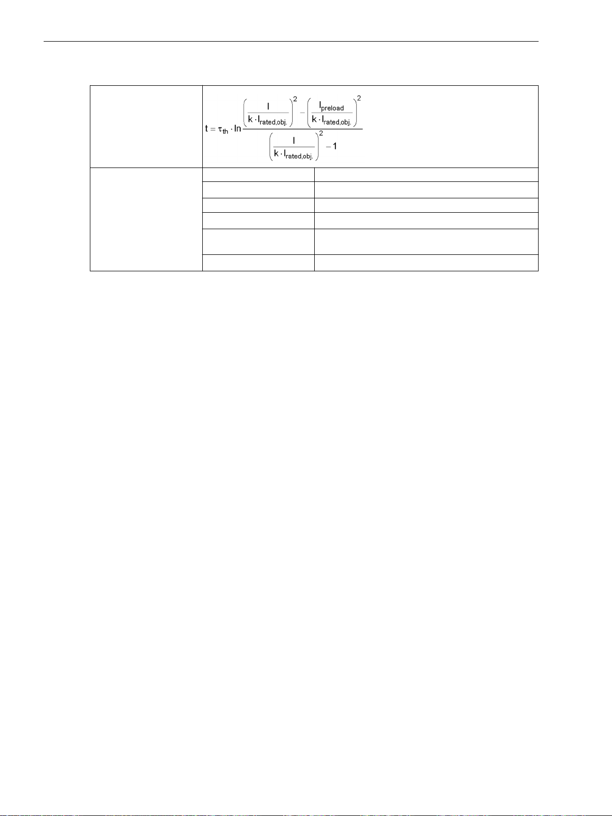
Technical Data
11.31 Thermal Overload Protection, 3-Phase – Advanced
Operate Curve
Operate curve
Where t Operate time
τ
th
I Current load current
I
preload
k Setting factor according to VDE 0435 part 3011 or
I
rated, obj
Time constant
Preload current
IEC 60255-149 (K factor)
Rated current of the protected object
1192 SIPROTEC 5, High-Voltage Bay Controller, Manual
C53000-G5040-C015-A, Edition 05.2018
Page 98
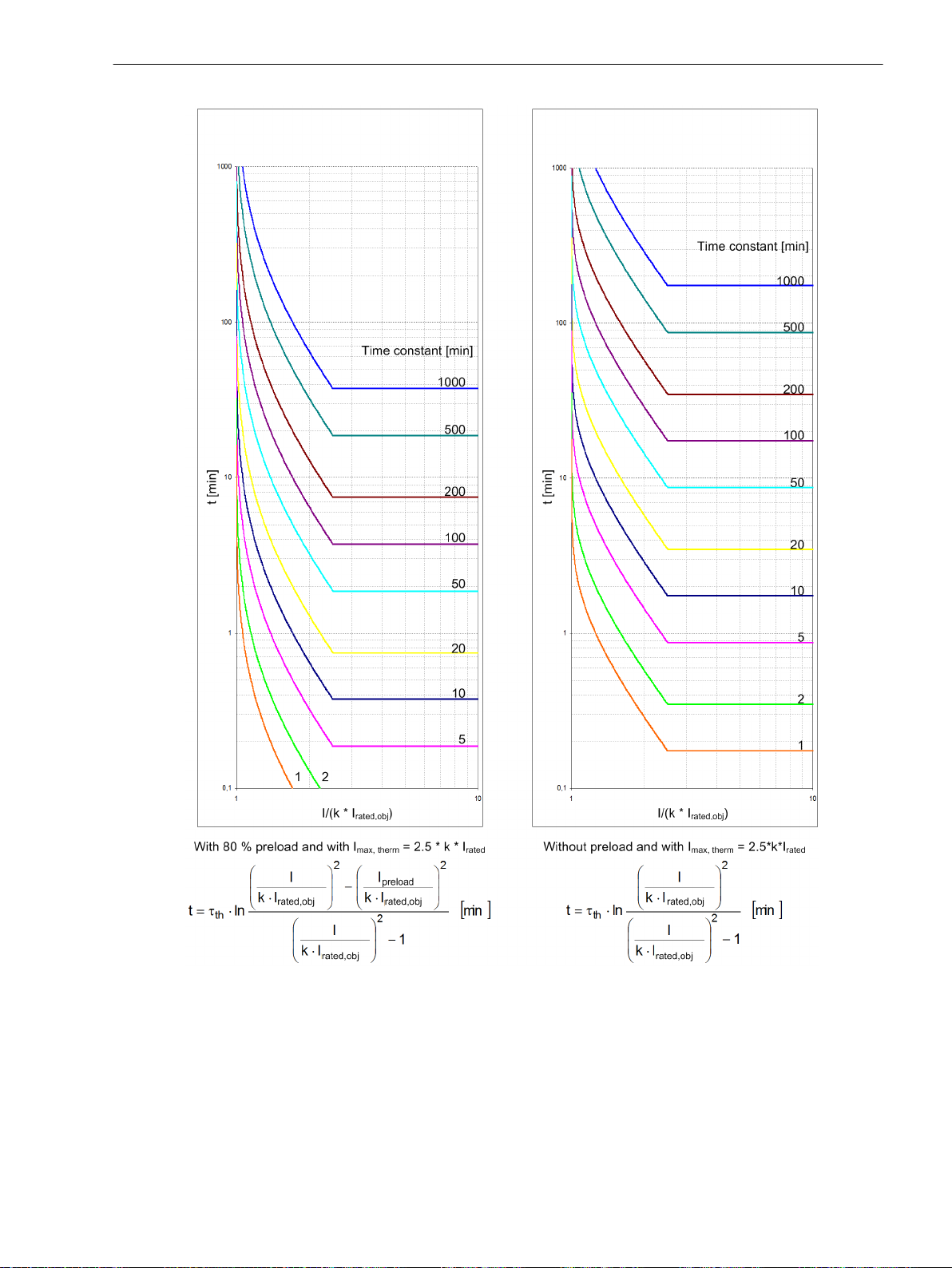
Technical Data
11.31 Thermal Overload Protection, 3-Phase – Advanced
[dwauslke-100611-01.tif, 1, en_US]
Figure 11-15
Operate Curve of Overload Protection
SIPROTEC 5, High-Voltage Bay Controller, Manual 1193
C53000-G5040-C015-A, Edition 05.2018
Page 99
Technical Data
11.32 Thermal Overload Protection, 1-Phase
11.32
Thermal Overload Protection, 1-Phase
Setting Values/Increments for the Protection Stage
Threshold current
warning
1 A @ 50 and 100 Irated 0.030 A to 35.000 A Increments of 0.001 A
5 A @ 50 and 100 Irated 0.15 A to 175.00 A Increments of 0.01 A
1 A @ 1.6 Irated 0.001 A to 1.600 A Increments of 0.001 A
5 A @ 1.6 Irated 0.005 A to 8.000 A Increments of 0.001 A
Threshold thermal warn. 50 % to 100 % Increments of 1 %
Dropout threshold operate 50 % to 99 % Increments of 1 %
K-factor acc. to IEC 60225-149 0.10 to 4.00 Increments of 0.01
Thermal time constant 10 s to 60 000 s Increments of 1 s
Imax thermal 1 A @ 50 and 100 Irated 0.030 A to 10.000 A Increments of 0.001 A
5 A @ 50 and 100 Irated 0.15 A to 50.00 A Increments of 0.01 A
1 A @ 1.6 Irated 0.001 A to 1.600 A Increments of 0.001 A
5 A @ 1.6 Irated 0.005 A to 8.000 A Increments of 0.001 A
Temperature rise at Irated 40 K to 200 K Increments of 1 K
Default temperature -55°C to 55°C Increments of 1°C
Minimal temperature -55°C to 40°C Increments of 1°C
Dropout Ratios
Tripping threshold (fixed at 100 %)
Thermal warning threshold About 0.99 of the setting value
Current warning threshold About 0.95 of the setting value
Dropout if value drops below operate indication
dropout threshold
Frequency Range of the Input Signals
The function captures input signals up to the 50th harmonic.
Tolerances
With reference to k ⋅ I
rated
With reference to the
operate time
Up to 30th harmonic 2 % or 10 mA ( I
or 50 mA ( I
rated
rated
= 5 A),
2 % class acc. to IEC 60255-149
Up to 50th harmonic,
f
= 50 Hz
rated
4 % or 20 mA ( I
or 100 mA ( I
rated
rated
= 5 A),
4 % class acc. to IEC 60255-149
Up to 50th harmonic,
f
= 60 Hz
rated
5 % or 25 mA ( I
or 125 mA ( I
rated
rated
= 5 A),
5 % class acc. to IEC 60255-149
Up to 30th harmonic 3 % or 1 s for I/(k ⋅ I
3 % class acc. to IEC 60255-149
= 1 A)
= 1 A)
= 1 A)
) > 1.25,
rated
1194 SIPROTEC 5, High-Voltage Bay Controller, Manual
C53000-G5040-C015-A, Edition 05.2018
Page 100
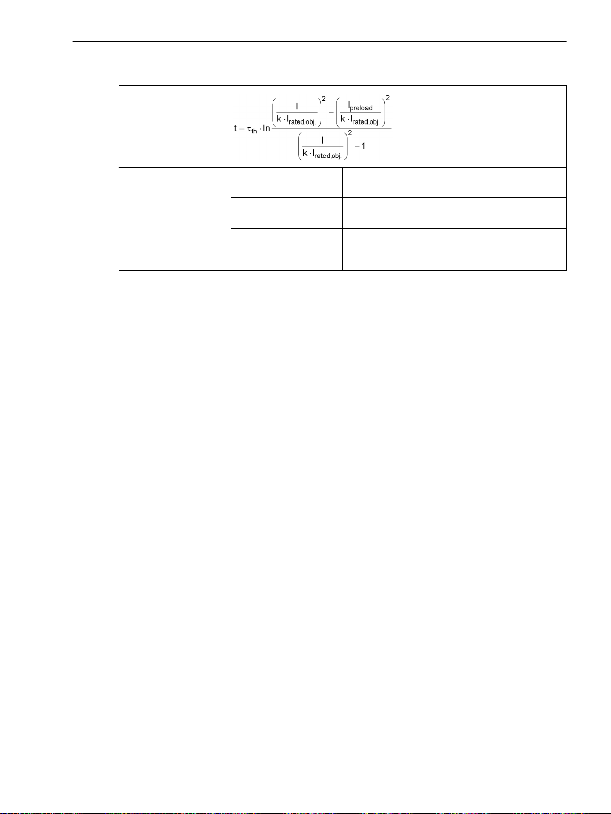
Operate Curve
Operate curve
Where t Operate time
Technical Data
11.32 Thermal Overload Protection, 1-Phase
τ
th
Time constant
I Current load current
I
preload
Preload current
k Setting factor according to VDE 0435 part 3011 or
IEC 60255-8 (K factor)
I
rated, obj
Rated current of the protected object
SIPROTEC 5, High-Voltage Bay Controller, Manual 1195
C53000-G5040-C015-A, Edition 05.2018
 Loading...