

Page 1
Powers
Controls
Technical Instructions
VP 658 S and VP 658 SC Powertop
Table 1.
Product Number
Valve Type
Valve Size
TM
Sequence and Sequence
Changeover Valves
Description
Features
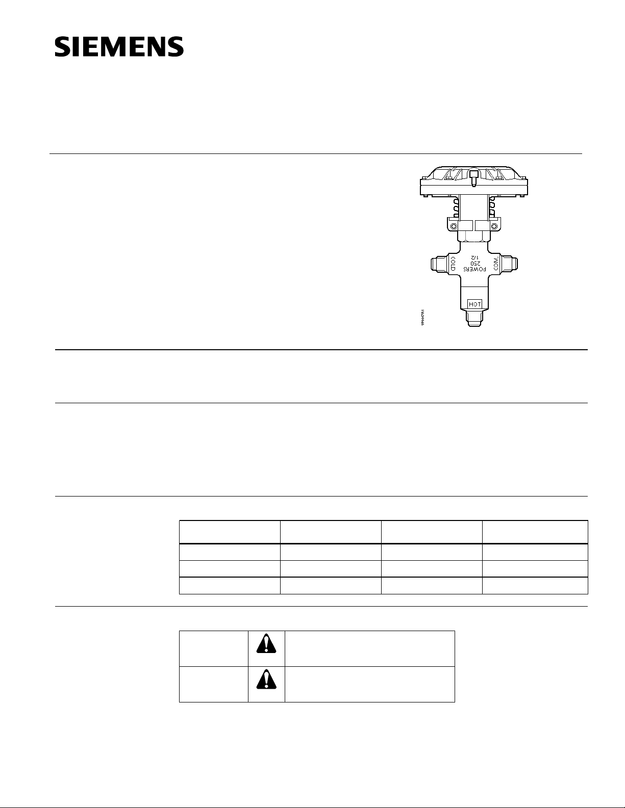
The VP 658 S sequence and VP 658 SC sequence changeover valves are designed to
select and modulate the flow of either hot or chilled water without mixing for radiant panel
and similar four-pipe single coil/panel applications. The sequence valve has two inlets
and one outlet whereas the changeover valve has one inlet and two outlets.
• Stainless steel stem for smooth operation and durability
• Large diaphragm area for control accuracy arid tight close off
• Removable actuator for ease of servicing
• Durable actuator made to eliminate electrolytic action
• Replaceable disc assemblies
• Matched sequencing of control and changeover valves
Document No. 155-092P25
VP 658-4
November 20, 2008
Product Numbers
658-0050 1.5 Sequence 1/2”
658-0051 2.5 Sequence 1/2”
658-0052 2.5 Changeover 1/2“
Warning/Caution Notations
WARNING
CAUTION
Siemens Industry, Inc.
Personal injury/loss of life may occur if
you not perform a procedure as
specified.
Equipment damage, or loss of data
may occur if you do not perform a
procedure as specified.
CV
Page 2

Technical Instructions
Valve size/ capacity See Tables 1 and 2.
Body Bronze
Nominal spring range See Figure 1.
Controlled medium Water, ethylene glycol solution
Document No. 155-092P25
November 20, 2008
Specifications
Valve Body
Material
Valve Actuator
Operating
Body Style 1/2” SAE Flared
Body type Sequence 2 inlets, 1 outlet
Changeover 1 inlet, 2 outlets
Action Normally Open (NO) Hot to common
Normally Closed (NC) Cold to
common
Valve stroke 13/32-inch (10 mm)
Seat Bronze
Stem Stainless steel
Stem packing (O-rings) EP rubber
Shut-off disc Buna-N
Throttle plug Brass
Diaphragm
Effective area 11 inch
Material EP rubber
Max. air pressure 30 psig (210 kPa)
Flow characterization:
Sequence Equal percentage
Changeover Quick opening
Ambient temperature range 35°F to 140°F (2°C to 60°C)
Body rating, max temperature/pressure See Table 3.
Max. pressure difference between hot
and cold ports:
Sequence 50 psig (350 kPa)
Changeover 10 psig (69 kPa)
Max. differential pressure
for modulating service (sequence) 25 psi (170 kPa)
Dimensions See Figure 8.
2
(71 cm2)
Application
Page 2 Siemens Industry, Inc.
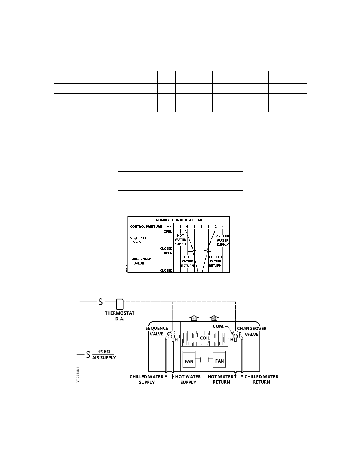
A typical application of sequence and changeover valves controls heating or cooling in a
single coil or radiant panel. These four-pipe systems have hot water and chilled water
available at the same time. Figure 2 shows a unit conditioner application.
The direct acting thermostat gradually positions the sequence valve and the changeover
valve to maintain space temperature according to the control schedule shown in
Figure 1. The sequence valve gradually controls the hot or chilled water flow into the
coil. The changeover valve diverts the water leaving the coil to the correct return line.
Page 3
VP 658 S and VP 658 SC Powertop Sequence and Sequence Changeover Valves Technical Instructions
Pressure Differential psi
2
4 6 8
10
15
20
25
Temperature
Pressure
Bronze Body
Figure 2. Unit Conditioner Application.
Document No. 155-092P25
November 20, 2008
Table 2. Water Capacity - U.S. Gallons Per Minute.
Valve Size and Type
CV 1
1/2" Sequence 1.5 2.1 3 3.7 4.2 4.7 5.8 6.7 7.5
1/2" Sequence 2.5 3.5 5 6.1 7.1 7.9 9.7 11.2 12.5
1/2" Changeover 2.5 - - - - - - - -
Table 3. Body Rating.
°F (°C)
psig (kPa)
ANSI Class 250
-20 to 150 (-30 to 66) 250 (1720)
200 (93) 250 (1720)
250 (121) 250 (1720)
Overall rating limited to 250 psig.
Siemens Industry, Inc. Page 3
Figure 1. Nominal Control Schedule.
Page 4
Technical Instructions
Document No. 155-092P25
November 20, 2008
Operation
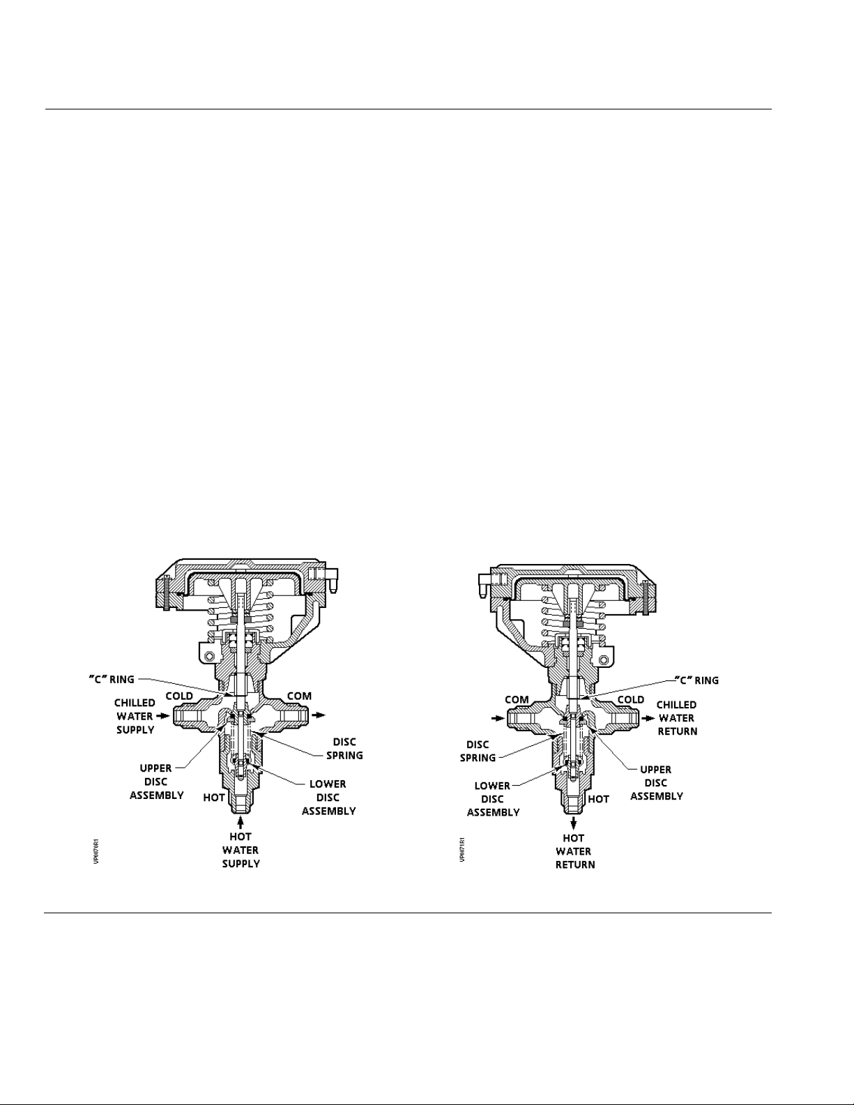
The sequence valve, (Figure 3), is piped to the inlet of a coil. Therefore, it has hot water
supply and chilled water supply connected to it. The changeover valve, (Figure 4), is piped
to the outlet of the coil. Therefore, it has the hot water and chilled water returns connected to
it. For the sequence valve, water should flow into the hot and cold ports and out of the
common. For the changeover valve, flow should be into the common and out of the hot and
cold ports.
The operation of the sequence valve and changeover valve is similar. The main difference is
the control pressure at which the upper port opens and the lower port closes on each valve.
With no air pressure to the Powertop the chilled water port (upper disc) is closed and the hot
water port (lower disc) is open. As air pressure increases, the lower disc is gradually moved
toward its seat, reducing the flow of hot water. After the lower disc closes against its seat,
stopping the flow of hot water, there is a dwell period (dependent upon water differential
pressures) during which there is no flow through the valve. As the control air pressure
continues to increase, it overcomes the disc spring force to gradually move the upper disc
away from the seat permitting the flow of cold water.
As the differential water pressure increases, the hot port (lower disc) will close at a higher
Powertop pressure and cold port (upper disc) opens at a lower Powertop pressure. The
effect is to narrow the dwell period.
Figure 1 shows the nominal control schedule for the sequence and changeover valves.
Figure 3. Sequence Valve.
Page 4 Siemens Industry, Inc.
Figure 4. Changeover Valve.
Page 5

VP 658 S and VP 658 SC Powertop Sequence and Sequence Changeover Valves Technical Instructions
Document No. 155-092P25
November 20, 2008
Sizing
The sizing of a valve is important for correct system operation. An undersized valve will
not have sufficient capacity at maximum load. An oversized valve may initiate cycling
and the seat and disc may be damaged because of the restricted opening. Correct
sizing of the control valve for actual expected conditions is considered essential for good
control.
Some variables that must be determined are:
1. The maximum inlet temperature and pressure of medium at the valve.
2. The pressure differential that will exist across the valve under maximum load
demand.
3. The maximum capacity the valve must deliver.
4. The maximum medium pressure differential the valve actuator must close against.
5. See AB-1 “Valve Selection and Sizing” for further recommendations.
See TabIe 2 for valve capacity.
The Powertop sequence changeover valve does not require sizing in the same manner
as the sequence valve. The changeover valve does not control the quantity of water
flowing through the system but diverts the flow from one return to the other.
NOTE: Even though it is not necessary to "size" a changeover valve, the pressure
drop across the valve will add resistance to the flow of the medium.
Installation
• Leave plastic cover in place until after painting.
• In concealed installations, sufficient room should be allowed so that the actuator
assembly can be removed for valve servicing. A distance of three inches (76 mm)
from top of housing is sufficient.
• Install changeover valve so that flow is out of the ports marked "hot" and "cold". The
inlet is the common port.
• Install sequence valve so that flow is into the ports marked "hot" and "cold". The
outlet is the common port.
• The valve housing should never be used as a lever arm to tighten the body when
taking up on a thread.
• For best performance install the valve vertically in an upright position.
• Installation of hand valves on supply and return piping is recommended to allow
servicing.
Siemens Industry, Inc. Page 5
Page 6
Technical Instructions
Part Number
seq.
seq.
c.o.
Document No. 155-092P25
November 20, 2008
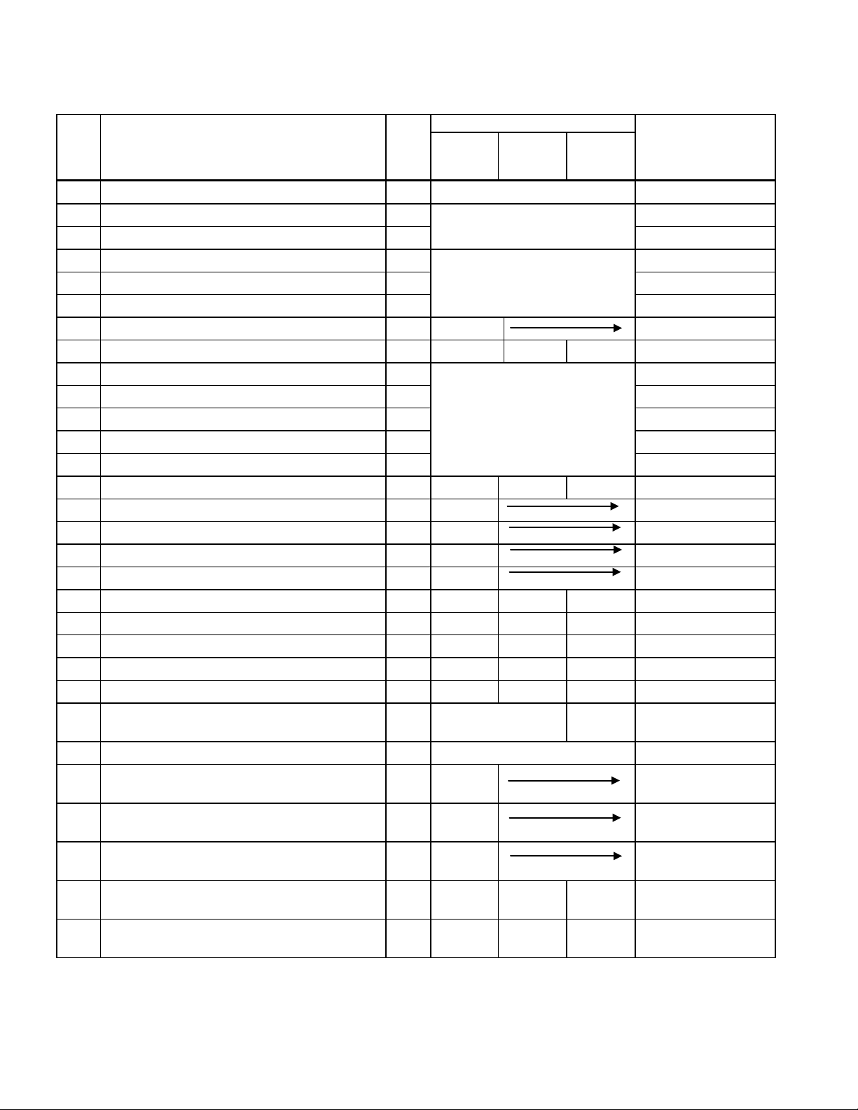
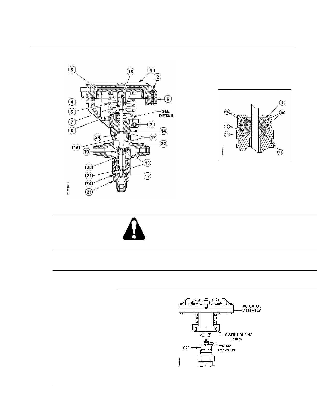
Table 4. Part Numbers (See Figure 5).
Item Description Qty
CV = 1.5
CV = 2.5
CV = 2.5
Material
1 Actuator Housing - Upper 1 See Item 26 Assembly. Nylon
2 Thread Forming Screw 8 See Item 27 Kit
3 Diaphragm 1 EP Rubber
or Item 26 Assembly.
4 Piston Plate Assembly 1
5 Actuator Compression Spring 1 Cadmium Pl. Steel
See Item 26 Assembly.
Steel
Aluminum & Steel
6 Actuator Housing - Lower 1 Nylon
7 Stem Locknut 2 041-117J Steel
8 Cap 1 - - - Brass
9 Packing Washer 1
Copper
10 Large O-Ring 2 EP Rubber
11 Small O-Ring 2 EP Rubber
See Item 28 Kit.
12 O-Ring Retainer 2 Brass
13 Packing Ring 1 Teflon
14 Bonnet 1 - - - Brass
15 Stem 1 658-356 Stainless Steel
16 Spacer 1 656-321 Brass
17 "C" Ring 3 047-064 Stainless Steel
18 "O" Ring 2 047-004 Buna-N
19 Upper Disc Assembly 1 656-265 656-365 Item 28 Brass & Sty. Buta.
20 Disc Spring 1 656-419 656-419 656-418 Stainless Steel
21 Lower Disc Assembly 1 656-266 656-330 Item 28 Brass & Sty. Buta.
22 Valve Body 1 - - - Bronze
23 Lower Body 1 - - - Brass
24 O-Ring 2 See Item 30 Ass'y. Items 29
EP Rubber
and 30
25 Back-Up Ring 2 See Item 28 Kit Teflon®
26 Actuator Assembly Includes Items 1, 2, 3, 4,
5, and 6
27 Diaphragm Kit Includes Items 2, 3 (Pkg. of 5
Diaphragms)
28 Stem Packing Kit Includes Items 9 through
13, 24, and 25 (For 10 valves)
29 Disc Assembly Kit Includes Items 19, 21,
- 658-066
- 658-166
- 658-167
- N/A N/A 657-813 -
-
-
-
and 24
30 Valve Body Assembly, Flared Includes Item
- 658-333 658-334 658-341 -
7 through 25
Page 6 Siemens Industry, Inc.
Page 7
VP 658 S and VP 658 SC Powertop Sequence and Sequence Changeover Valves Technical Instructions
WARNING:
Document No. 155-092P25
November 20, 2008
Valve Components
Detail of Stem Packing.
Figure 5. Valve Construction (See Table 4).
Service
Before doing any service work, shut off the medium (water, etc.) to the
valve and remove and cap the airline to the valve actuator to prevent
personal injury and equipment damage.
Diaphragm
Installation instructions are packaged with the replacement kit.
Replacement
Stem Packing
Replacement
See TB 246 (155-301P25) VP 658 Powertop Valve Repacking Kit for recommended
procedure.
Figure 6. Actuator Assembly Removal.
Siemens Industry, Inc. Page 7
Page 8

Technical Instructions
The replacement is now complete.
Document No. 155-092P25
November 20, 2008
Actuator
Assembly
Replacement
Valve Disc
Replacement
Disassembly
1. Loosen the two lower housing screws that clamp it to the bonnet.
2. Using two open-end wrenches, loosen the stem locknuts.
3. Unscrew actuator assembly from stem and remove it, as shown in Figure 6.
4. Before installing new actuator assembly, push stem down. There must be at least
1/16-inch (2 mm) clearance between lower stem locknut and cap.
5. Pull stem up and install actuator assembly.
6. Screw stem into piston plate and tighten locknuts.
7. Tighten lower housing screws. Don't overtighten these screws.
The replacement is now complete.
1. Remove actuator as described in the Actuator Assembly Replacement section.
2. Remove stem locknuts.
3. Remove lower body and pull stem assembly through bottom port.
4. Place stem assembly in a vise. Hold assembly by upper disc assembly, NOT BY THE
STEM. The stem must be smooth to provide a good seal and move freely. Place 1/2-inch
(13 mm) open-end wrench on lower disc assembly and compress disc spring so "C" ring
can be pulled out with long nose pliers. Be careful; disc spring has a lot of force.
Assembly
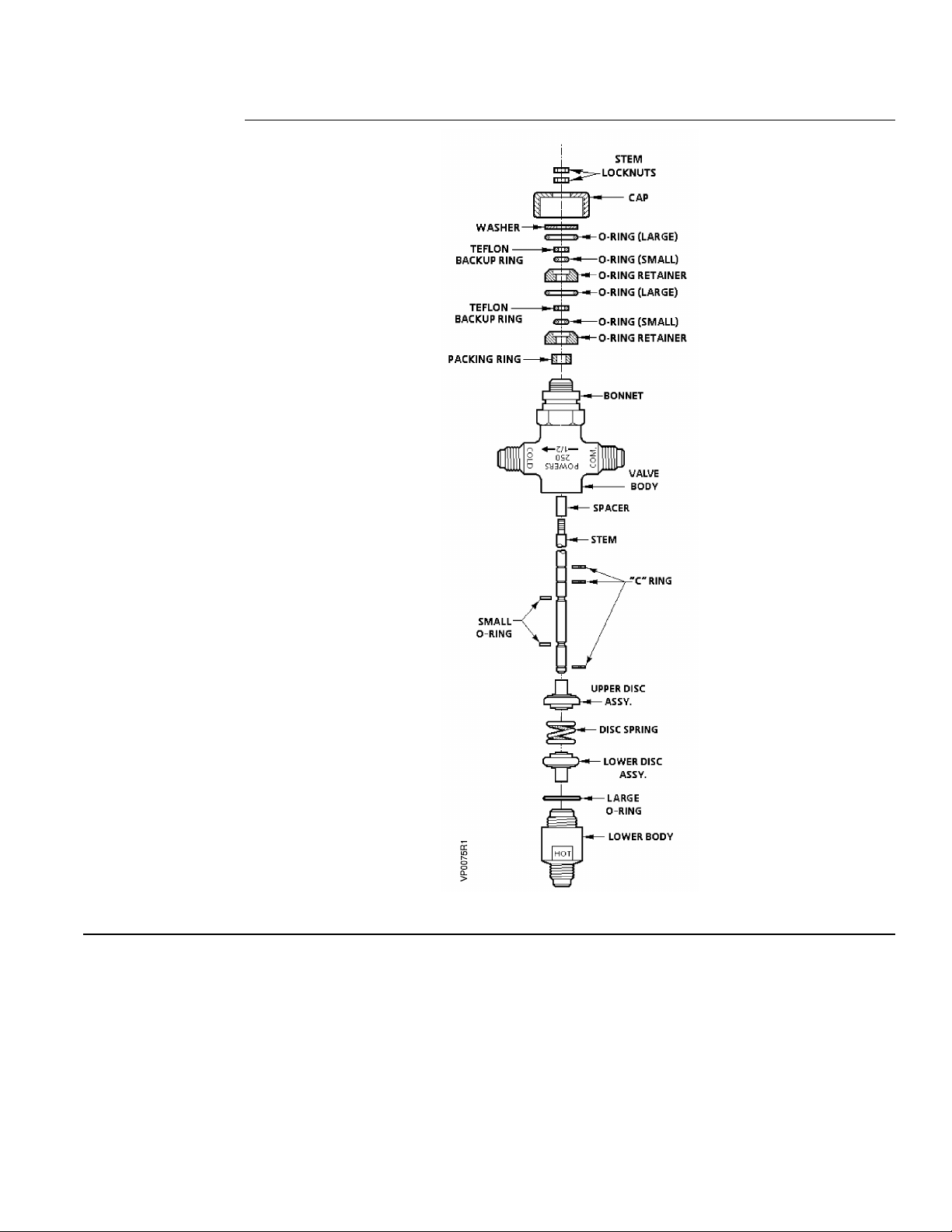
5. Disassemble as shown in Figure 7. Upper and lower disc assemblies can now be
removed and replaced.
6. If small O-rings need to be replaced, use a small screwdriver to free them from groove.
7. Remove the cap from the bonnet. Then remove the washer, O-ring packing, and packing
ring as shown in Figure 7.
1. Reassemble stem assembly. See step 4 in the Disassembly section and Figure 7. Be
careful, it requires considerable force to compress disc spring so "C" ring can be
replaced on valve stem. Slide stem assembly into bonnet.
2. Return lower body to bottom of valve body and tighten securely.
3. Replace packing ring, O-rings packing and washer using repacking kit 658-167. Follow
recommended procedure outlined in TB246 included in 658-167 kit. Packing must be
replaced because it is normally damaged during disassembly.
4. When packing has been replaced and valve body is reassembled, replace actuator
assembly by reversing steps 1 through 3 in the Actuator Assembly Replacement section.
Page 8 Siemens Industry, Inc.
Page 9
VP 658 S and VP 658 SC Powertop Sequence and Sequence Changeover Valves Technical Instructions
Document No. 155-092P25
November 20, 2008
Valve Disc
Replacement,
continued
Figure 7. Valve Body Assembly.
Siemens Industry, Inc. Page 9
Page 10
Technical Instructions
Siemens Industry, Inc.
+ 1 847-215-1000
Your feedback is im portant to us. If you have
Document No. 155-092P25
Document No. 155-092P25
November 20, 2008
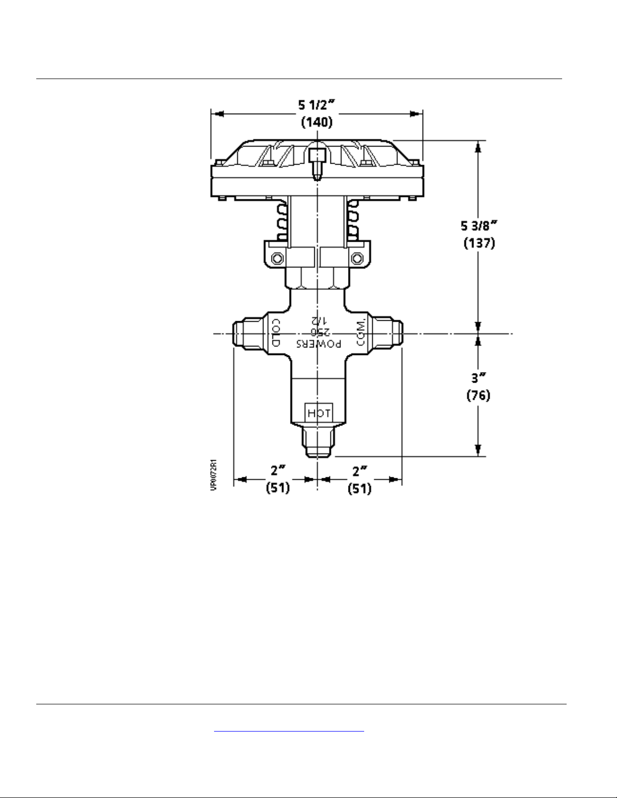
Dimensions
Information in this publication is based on current specificati ons. The company reserves the right to make changes i n specifications and models as
design improvements are introduced. Powers is a registered trademark of Siem ens Industry, Inc. Product or company names mentioned herein
may be the trademarks of their respective owners. © 2008 Siemens Industry, Inc .
Building Technologies Divis i on
1000 Deerfield Parkway
Buffalo Grove, IL 60089
Figure 8. Dimensions.
comments about this document, please send them
to [email protected]
Printed in the USA
Page 10
 Loading...