

Page 1
Powers
Controls
Technical Instructions
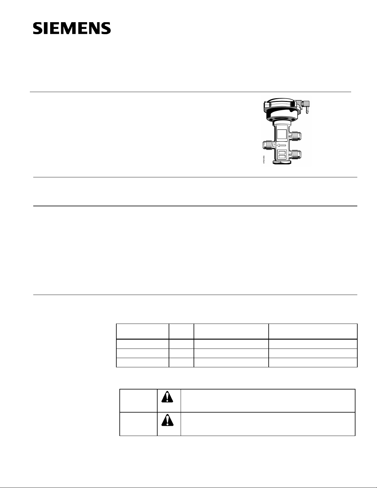
The VP 656 Powermite Three-way Mixing Valves are designed for water mixing
Spring
Rating
WARNING
TM
VP 656 Powermite
Three-way Mixing Valves
(Flared Type)
Document No. 155-086P25
VP 656-3
March 7, 2005
Description
Features
applications. The valve body is a high grade bronze forging with connections for 1/2-in
O.D. SAE flare fittings.
• Optimum flow/constant discharge capacity provided by use of a specially designed
• Enclosed actuator housing to protect the diaphragm, spring. etc.
• Small size allows installation in restricted space.
• Actuator can be rotated to facilitate air connection.
• Stainless steel valve stem to reduce friction and corrosion.
Product Numbers
Product Number
Warning/Caution Notations
plug at the throttling port, Normally Open (NO), and a complementary plug at the
bypass port, Normally Closed (NC).
Table 1.
Cv
656-0009 2.5 10-15 Ib (69-103 kPa) .5 (.13)
656-0010 2.5 3-8 lb (21 -55 kPa) .5 (.13)
656-0011 1.5 3-8 lb (21-55 kPa) .5 (.13)
Valve Size In (mm)
Personal injury/loss of life may occur if you do not perform a
procedure as specified.
CAUTION
Equipment damage, or loss of data may occur if you not perform a
procedure as specified.
Siemens Industry, Inc.
Page 2

Technical Instructions
Valve size/capacity See Table 2.
Nominal spring span 5 psi (34.5 kPa)
Valve
(inches)
Pressure Differential - psi
Document No. 155-086P25
March 7, 2005
Specifications
Valve Body
Valve Actuator
Operating
Valve body style Flared End
Valve action Upper seat normally closed
Bottom seat normally open
Valve stroke 3/8-inch (9.5 mm)
Valve body rating 300 psig @ 350°F
(2068 kPa @ 177°C)
Flow characteristic (B port) Modified equal percentage
Effective diaphragm area 3.4 inch2 (21.9 cm2)
Maximum air supply to diaphragm 30 psig (207 kPa)
Air connection 1/8” N.P.T.
Standard spring ranges P=10 psi (68.9 kPa)
3 to 8 psi (20.7 to 55.2 kPa)
10 to 15 psi (68.9 to 103.4 kPa)
Controlled medium Water, Ethylene glycol solution
Maximum fluid temperature 250°F (121°C)
Maximum inlet pressure 300 psig (2068 kPa)
Maximum recommended differential pressure for
modulating service
Between inlets 25 psi (172 kPa)
Between inlet and outlet 25 psi (172 kPa)
Shipping weight 2.0 lb (0.9 kg)
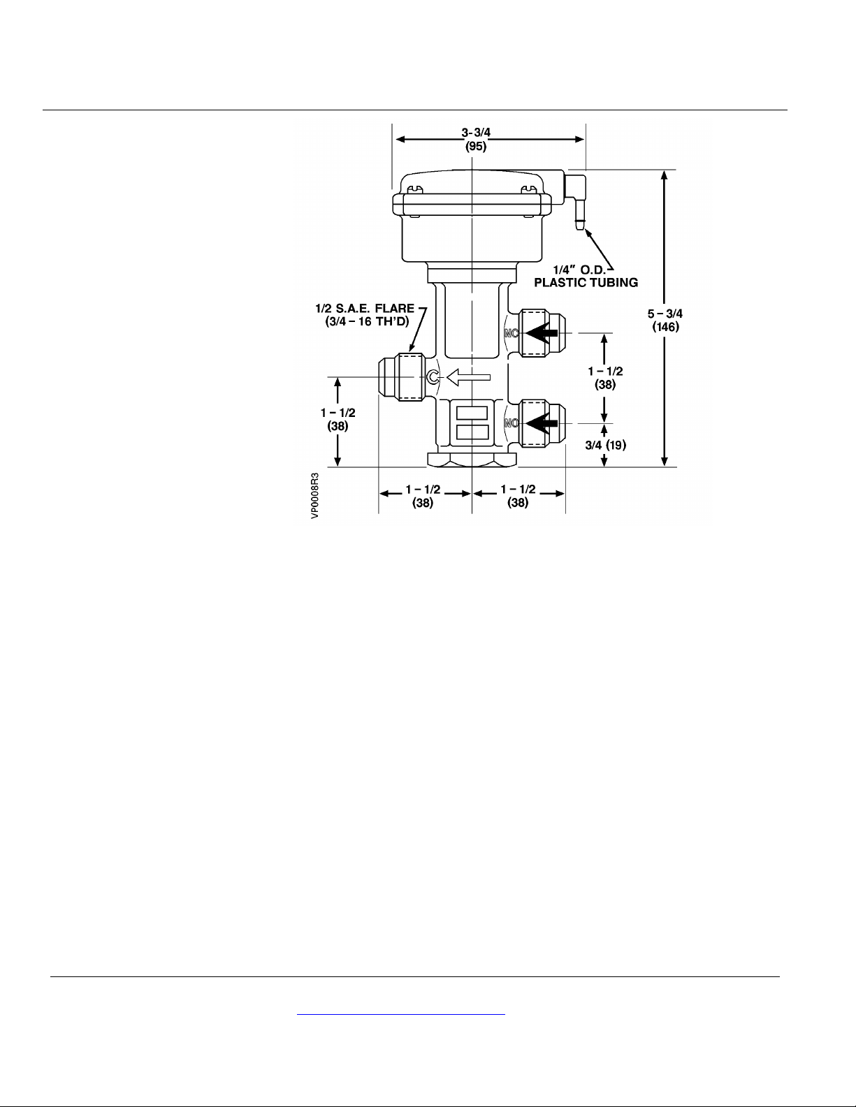
Dimensions See Figure 3.
Table 2. Maximum Water Capacity - US Gallons per Minute.
Size
1/2 1.5 2.1 2.6 3.0 3.4 3.7 4.0 4.2 4.5 4.7 5 5.2 5.4 5.6 5.8 6.7 7.5
1/2 2.5 3.5 4.3 5.0 5.6 6.1 6.6 7.1 7.5 7.9 8.3 8.7 9 9.3 9.7 11.2 12.5
Cv1
Applications
2 3 4 5 6 7 8 9 10 11 12 13 14 15 20 25
VP 656 Three-way Mixing Valves are recommended for mixing hot or chilled water for
convectors, fan coil units, unit conditioners, radiation, reheat coils, and similar terminal
units requiring water mixing. The dual sealing packed construction allows applications
for higher pressure system encountered in high rise buildings.
Applications requiring a modified equal percentage flow characteristic must be piped so
the NO port controls the flow to the coil.
Typical uses are schools, office buildings, hotels, hospitals, factories, and other sites
where efficient, economical water mixing is desired. The small, overall size lends itself
to installation within cabinet enclosures, etc., where available space is limited.
Page 2 Siemens Industry, Inc.
Page 3
VP 656 Powermite Three-Way Mixing Valves (Flared Type) Technical Instructions
Document No. 155-086P25
March 7, 2005
Operation
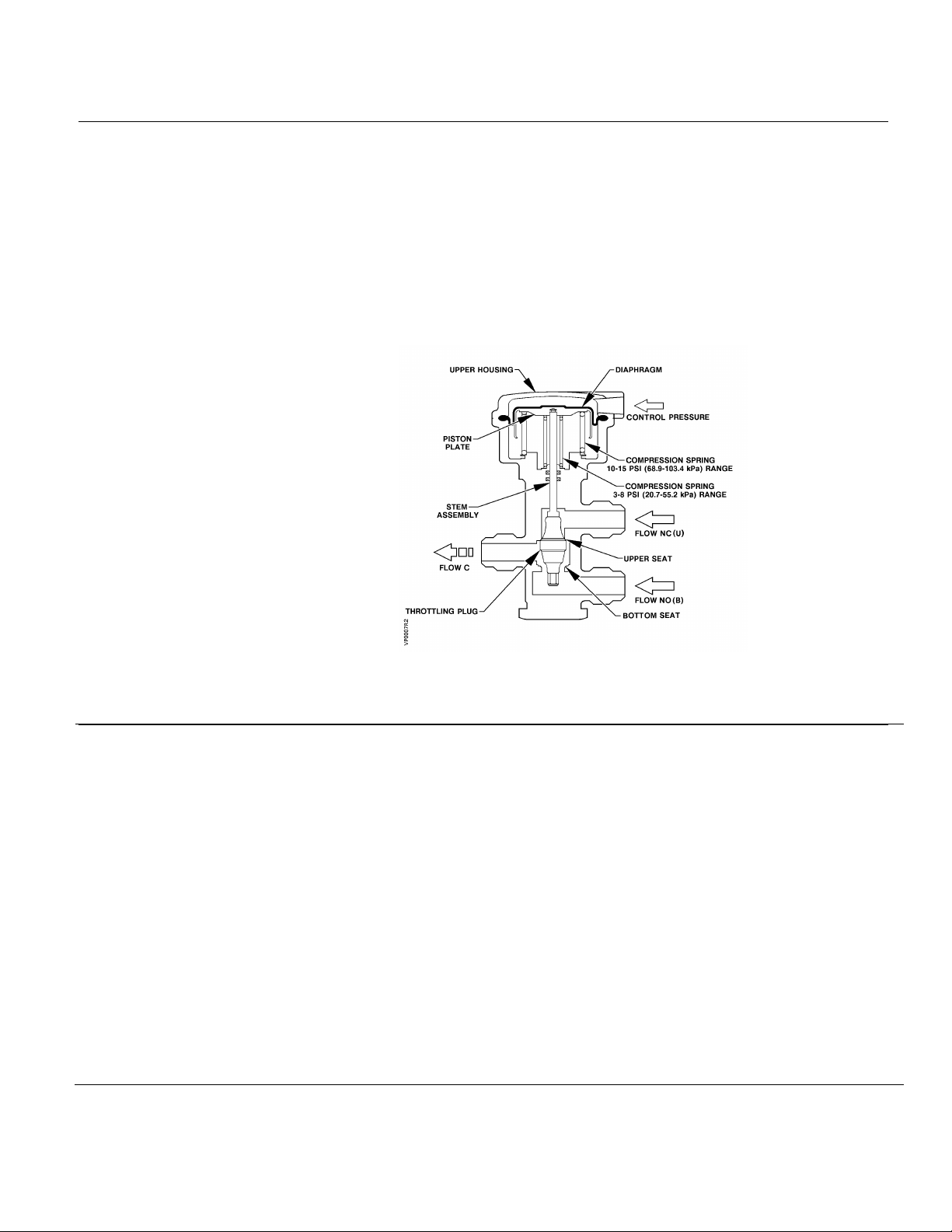
The control pressure from the controller is connected to the upper housing, above the
valve diaphragm. With no air pressure in the upper housing, the internal compression
spring exerts force against the piston plate which holds the stem assembly tight against
the upper seat permitting the flow from NO port to Common (C) port. An increase in
control pressure will overcome this spring force and the differential pressure of the
controlled medium to gradually move the stem assembly downward.
Full stem travel will bring the throttling plug in contact with the bottom seat for a
metal-to-metal close-off permitting the flow from the NC port to the C port.
The nominal spring span is identified as the change in air pressure required to operate the
valve from the opening of the upper port to the closing of the bottom port.
Sizing
Figure 1. Operation.
Correct sizing of the control valve for actual expected condition is essential for good control.
An undersized valve will not have sufficient capacity at maximum load. An oversized valve
may initiate cycling and the seat and disc may be damaged because of the restricted
opening.
Some variables that must be determined are:
1. The medium to be controlled; water, etc.
2. The maximum inlet temperature and pressure of medium at the valve.
3. The pressure differential that will exist across the valve under maximum load demand.
4. The maximum capacity the valve must deliver.
5. The maximum medium pressure differential the valve actuator must close against.
6. As the medium pressure differential across the valve increases, the spring span also
increases. This must be considered when sequencing valves.
7. Typical valve capacities are shown for water in Table 2. See AB-1 "Valve Selection and
Sizing" for further recommendations.
Siemens Industry, Inc. Page 3
Page 4
Technical Instructions
3-8 psi
10-15 psi
Document No. 155-086P25
March 7, 2005
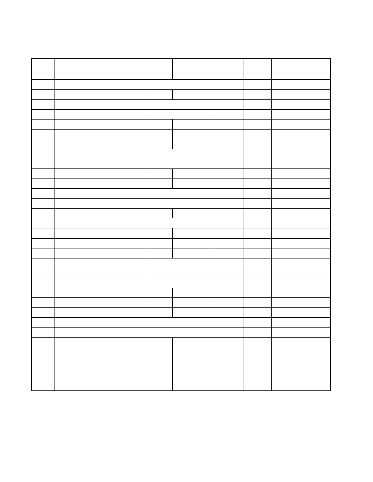
Table 3. Part Numbers (See Figure 2).
No. Name
1.5
C
v
Cv 2.5
Cv 2.5
No.
Req'd
1 E-ring See Items 29 and 30 Kits 1 Phos. Bronze
2 Piston Plate - - - 1 Brass
3 #8-32 × 7/16 Lg. Filister Hd. Scr. See Items 28 and 30 Kits 4 Steel
4 Diaphragm See Item 28 Kit 1 Rubber
5 Spring (3-8 psi only) - - - 1 Music Wire
6 Spring (10-15 psi only) - - - 1 Music Wire
7 Washer (10-15 psi only) - - - 1 Steel
8 Quad Ring Retainer See Items 29 and 30 Kits 1 Brass
9 Stem & Collar Assembly See Item 30 Kit 1 St. Steel
10 Lower Quad Ring Retainer - - - 1 Brass
11 Throttle Plug 656-345 656-346 656-346 1 Brass
12 Lower Seat See Item 30 Kit 1 Brass
13 Lower Seat Retainer See Item 30 Kit 1 Brass
14 Upper Housing - - - 1 Aluminum
15 Washer See Items 29 and 30 Kit 1 Brass
16
90° Elbow
- - - 1 Brass
17 Piston Cup - - - 1 Brass
18 Lower Housing - - - 1 Aluminum
19 Retaining Ring See Items 29 and 30 Kit 1 Steel
20 Retaining Ring See Items 29 and 30 Kit 1 St. Steel
21 Quad Ring See Items 29 and 30 Kit 2 E.P. Rubber
22 Spring - - - 1 Phos. Bronze
23 Stem Bearing - - - 1 Oilite
24 Valve Body - - - 1 Brass
25 Gasket See Item 30 Kit I Copper
26 Locknut See Item 30 Kit 1 Brass
27 Cap - - - 1 Brass
28 Diaphragm Kit 656-763 656-763 656-753 1 29 Stem Packing Items 1, 8,15,19,
656-601 656-601 656-601 1 -
20, 21
30 Rebuild/Repair Kit Items 1, 3, 8,
656-764 656-765 656-765 1 -
9, 12, 13, 15, 19, 20, 21, 25, 26
Material
Page 4 Siemens Industry, Inc.
Page 5
VP 656 Powermite Three-Way Mixing Valves (Flared Type) Technical Instructions
Document No. 155-086P25
March 7, 2005
Valve Components
Installation
Service
Throttling Plug
Replacement
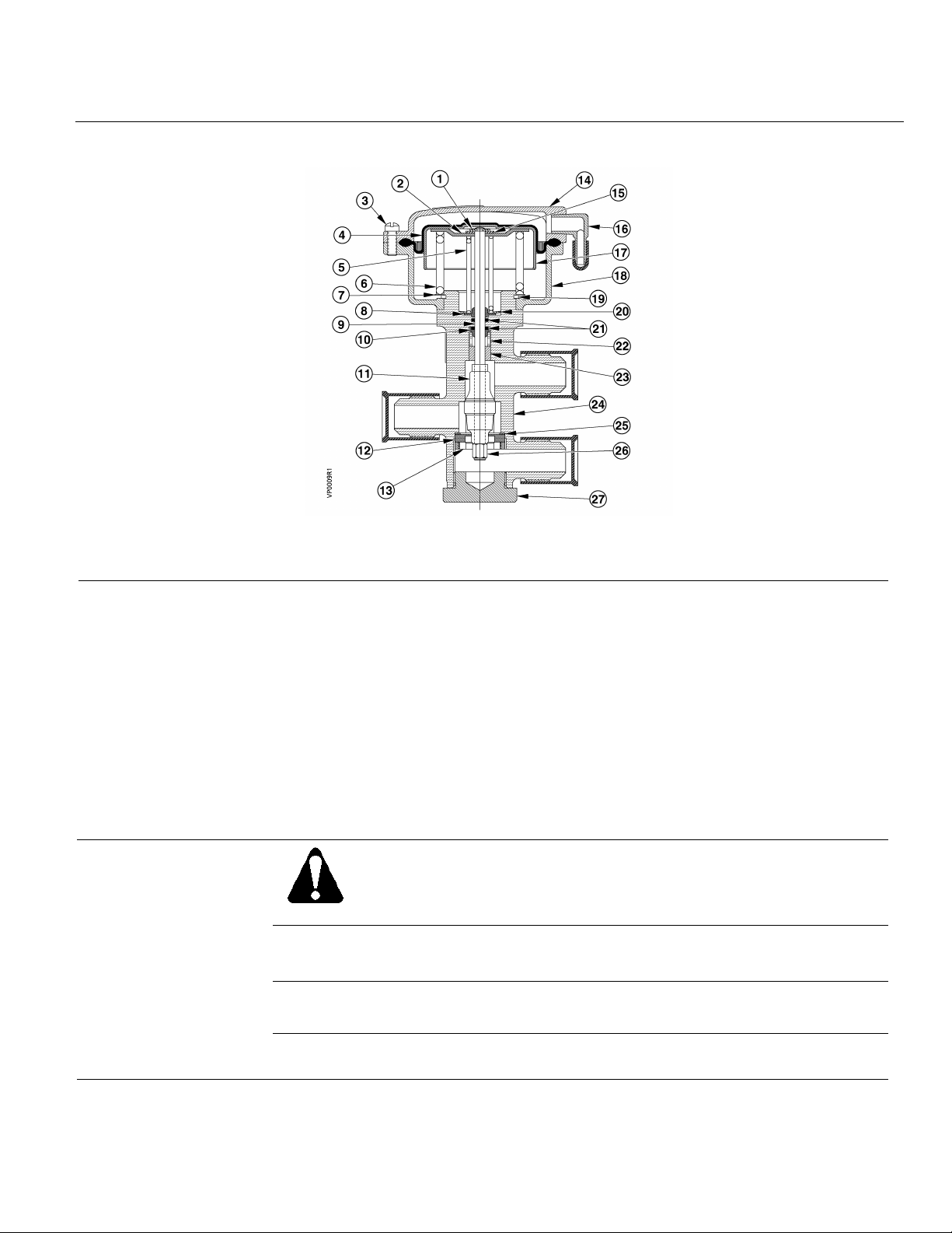
Figure 2. Valve Construction (See Table 3).
• It is not necessary to remove the valve top for normal installation.
• In concealed installations, sufficient room should be allowed so that the upper
housing can be removed for valve servicing. A distance of two inches (51 mm) from
top of the housing is sufficient.
• Flow should be into ports NC and NO and out of port C for the valve to operate
properly. Flow direction arrows are cast in the valve body.
• The valve housing should never be used as a lever arm to tighten the body when
taking up on a thread.
• The valve should be installed in a vertical, upright position.
• The valve top can be rotated to allow piping the control air from a convenient
direction.
WARNING:
Before doing any service work, shut off the medium (water, etc.) to the
valve and remove and cap the air line to the valve actuator to prevent
personal injury and equipment damage.
See TB 233 (155-240P25) for recommended procedure.
Valve Rebuilding/
Repacking
Diaphragm Replacement
Siemens Industry, Inc. Page 5
See TB 233 (155-240P25) for recommended procedure.
See TB 233 (155-240P25) for recommended procedure. Installation instructions are
packaged with the replacement kit.
Page 6
Technical Instructions
Siemens Industry, Inc.
+ 1 847-215-1000
Your feedback is im port ant to us. If you have
Document No. 155-086P25
Document No. 155-086P25
March 7, 2005
Dimensions
Figure 3. Dimensions in Inches (Millimeters).
Information in this publication is based on current s pecifications. The company reserves the right to mak e changes in specificati ons and models as
design improvements are introduced. Powers is a registered trademark of Siemens Indus t ry, Inc. Other product or company names mentioned
herein may be the trademarks of their respective owners. © 2005 Siemens Industry, Inc.
Building Technologies Divis i on
1000 Deerfield Parkway
Buffalo Grove, IL 60089
comments about this document, please send them
to [email protected]
Printed in the USA
Page 6
 Loading...