

Page 1
MICROMASTER 440
Parameter List Issue 01/06
User Documentation
6SE6400-5BB00-0BP0
Page 2
Available Documentation for the MICROMASTER 440
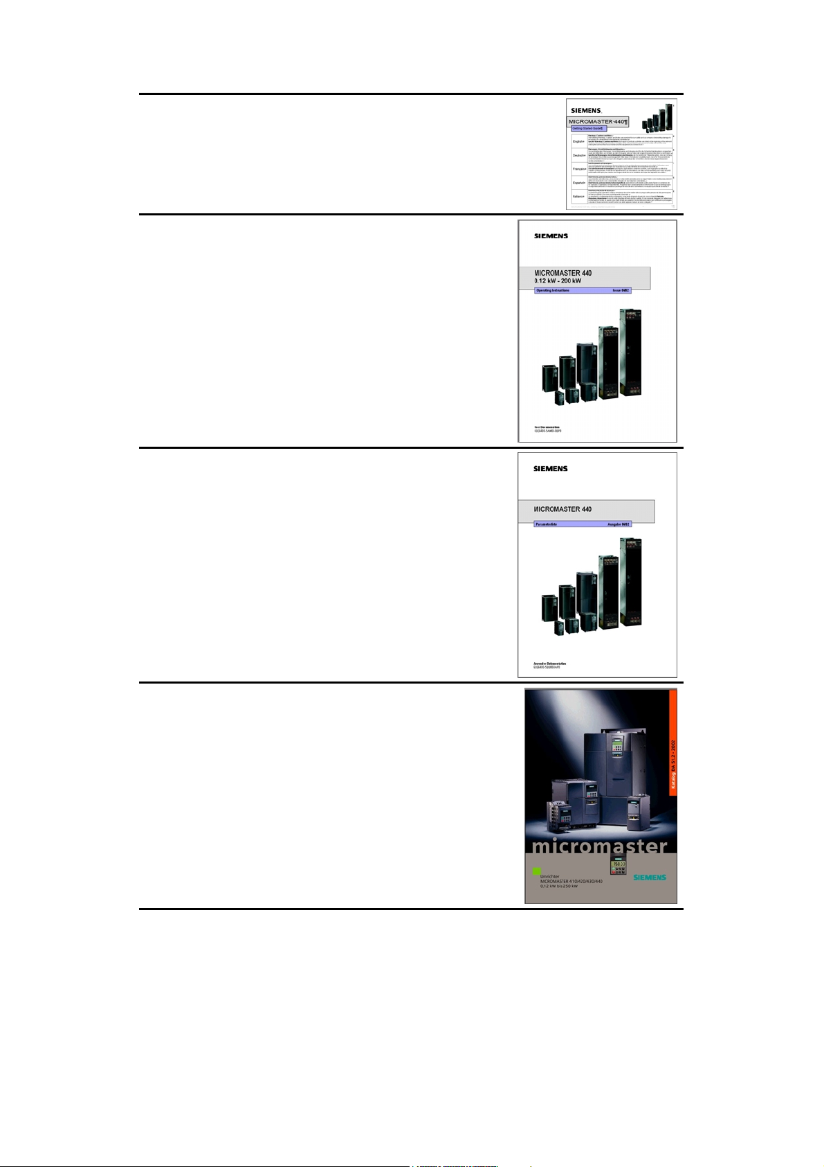
Getting Started Guide
Is for quick commissioning with SDP and BOP.
Operating Instructions
Gives information about features of the MICROMASTER
440, Installation, Commissioning, Control modes, System
Parameter structure, Troubleshooting, Specifications and
available options of the MICROMASTER 440.
Parameter List
The Parameter List contains the description of all
Parameters structured in functional order and a detailed
description. The Parameter list also includes a series of
function plans.
Catalogues
In the catalogue you will find all needs to select a certain
inverter, as well as filters chokes, operator panels or
communications options.
Page 3

MICROMASTER 440
Parameter List
User Documentation
Valid for Issue 01/06
Converter Type Software Version
MICROMASTER 440 V2.1
Block Diagram
and Terminals
Parameter List
Function Diagrams
Faults and Alarms
Abbreviations
Issue 01/06
Page 4

Notes Issue 01/06
Warning
!
Please refer to all Definitions and Warnings contained in the Operating Instructions.
You will find the Operating Instructions on the Docu CD delivered with your inverter. If
the CD is lost, it can be ordered via your local Siemens department under the Order
No. 6SE6400-5AD00-1AP0.
Information about MICROMASTER 440 is also available from:
Regional Contacts
Please get in touch with your contact for Technical Support in your Region for questions
about services, prices and conditions of Technical Support.
Central Technical Support
The competent consulting service for technical issues with a broad range of requirementsbased services around our products and systems.
Europe / Africa
Tel: +49 (0) 180 5050 222
Fax: +49 (0) 180 5050 223
Email: adsupport@siemens.com
America
Tel: +1 423 262 2522
Fax: +1 423 262 2589
Email: simatic.hotline@sea.siemens.com
Asia / Pacific
Tel: +86 1064 757 575
Fax: +86 1064 747 474
Email: adsupport.asia@siemens.com
Online Service & Support
The comprehensive, generally available information system over the Internet, from product
support to service & support to the support tools in the shop.
http://www.siemens.com/automation/service&support
Internet Address
Customers can access technical and general information under the following address:
http://www.siemens.com/micromaster
Printed in the Federal Republic of Germany
Approved Siemens Quality for Software and Training
is to DIN ISO 9001, Reg. No. 2160-01
The reproduction, transmission or use of this document, or its
contents is not permitted unless authorized in writing.
Offenders will be liable for damages. All rights including rights
created by patent grant or registration of a utility model or
design are reserved.
© Siemens AG 2001 - 2006 All Rights Reserved.
MICROMASTER® is a registered trademark of Siemens
Printed in the Federal Republic of Germany
MICROMASTER 440 Parameter List
4 6SE6400-5BB00-0BP0
Siemens-Aktiengesellschaft.
Other functions not described in this document may be
available. However, this fact shall not constitute an obligation
to supply such functions with a new control, or when
servicing.
We have checked that the contents of this document
correspond to the hardware and software described. There
may be discrepancies nevertheless, and no guarantee can be
given that they are completely identical. The information
contained in this document is reviewed regularly and any
necessary changes will be included in the next edition. We
welcome suggestions for improvement.
Siemens handbooks are printed on chlorine-free paper that
has been produced from managed sustainable forests. No
solvents have been used in the printing or binding process.
Document subject to change without prior notice.
Siemens-Aktiengesellschaft.
Page 5

Issue 01/06 Table of Contents
Parameters MICROMASTER 440
This Parameter List must only be used together with the Operating Instructions of the
MICROMASTER 440. Please pay special attention to the Warnings, Cautions, Notices
and Notes contained in these manuals.
Table of Contents
1 Block Diagram and Terminals ....................................................................7
1.1 Block Diagram ............................................................................................7
1.2 Power Terminals ........................................................................................8
1.3 Control Terminals .....................................................................................11
2 Parameters...............................................................................................12
2.1 Introduction to MICROMASTER System Parameters..............................12
2.2 Quick commissioning (P0010 = 1) ...........................................................15
2.3 Command and Drive Datasets - Overview...............................................17
2.4 Binector Input Parameters........................................................................21
2.5 Connector Input Parameters ....................................................................22
2.6 Binector Output Parameters.....................................................................22
2.7 Connector Output Parameters .................................................................23
2.8 Connector/Binector Output Parameters...................................................24
3 Parameter Description..............................................................................25
3.1 Common parameters................................................................................25
3.2 Diagnosis parameters ..............................................................................29
3.3 Inverter parameters (HW).........................................................................42
3.4 Motor parameters.....................................................................................50
3.5 Speed encoder .........................................................................................67
3.6 Application macros ...................................................................................69
3.7 Motor temperature....................................................................................69
3.8 Command source.....................................................................................75
3.9 Digital inputs.............................................................................................77
3.10 Digital outputs...........................................................................................84
3.11 Analog inputs............................................................................................86
3.12 Analog outputs .........................................................................................93
3.13 Parameter / command / drive data set.....................................................97
3.14 BICO command parameters.................................................................. 102
3.15 Communication parameters .................................................................. 105
3.16 Setpoint source ..................................................................................... 110
3.17 Fixed frequencies .................................................................................. 113
3.18 Motorized potentiometer (MOP)............................................................ 120
3.19 JOG ....................................................................................................... 122
3.20 Setpoint channel.................................................................................... 125
MICROMASTER 440 Parameter List
6SE6400-5BB00-0BP0
5
Page 6

Table of Contents Issue 01/06
3.21 Ramp-function generator....................................................................... 131
3.22 Flying restart.......................................................................................... 136
3.23 Automatic restart ................................................................................... 139
3.24 Motor holding brake............................................................................... 141
3.25 DC braking ............................................................................................ 143
3.26 Compound braking................................................................................ 146
3.27 Dynamic braking.................................................................................... 147
3.28 Vdc controller ........................................................................................ 148
3.29 Control mode......................................................................................... 153
3.29.1 V/f control technique.............................................................................. 156
3.29.1.1 Slip compensation ................................................................................. 162
3.29.1.2 Resonance damping ............................................................................. 163
3.29.1.3 Imax controller....................................................................................... 164
3.29.1.4 Soft starting ........................................................................................... 166
3.29.2 Field-orientated vector control............................................................... 167
3.29.2.1 Speed controller with/without encoder .................................................. 168
3.29.2.2 Droop..................................................................................................... 170
3.29.2.3 Speed controller pre-control.................................................................. 172
3.29.2.4 Torque control ....................................................................................... 173
3.29.2.5 Supplementary torque setpoint ............................................................. 176
3.29.2.6 Torque / power limiting.......................................................................... 177
3.29.2.7 Flux control............................................................................................ 179
3.29.2.8 Current controller................................................................................... 182
3.29.2.9 Motor model .......................................................................................... 183
3.30 Inverter parameters (Modulator) ........................................................... 188
3.31 Motor data identification ........................................................................ 189
3.32 Speed optimization................................................................................ 192
3.33 Reference parameters........................................................................... 192
3.34 Communication parameters (USS, CB) ................................................ 195
3.35 Faults, Alarms, Monitoring..................................................................... 207
3.36 Load torque monitoring ......................................................................... 218
3.37 Technology controller (PID controller)................................................... 222
3.38 Positioning down ramp.......................................................................... 239
3.39 Free function blocks (FFB).................................................................... 241
3.40 Inverter parameters............................................................................... 257
4 Function Diagrams ................................................................................ 259
5 Faults and Alarms ................................................................................. 307
5.1 Fault messages ..................................................................................... 307
5.2 Alarm Messages.................................................................................... 315
6 Abbreviations......................................................................................... 321
MICROMASTER 440 Parameter List
6 6SE6400-5BB00-0BP0
Page 7
Issue 01/06 Block Diagram and Terminals
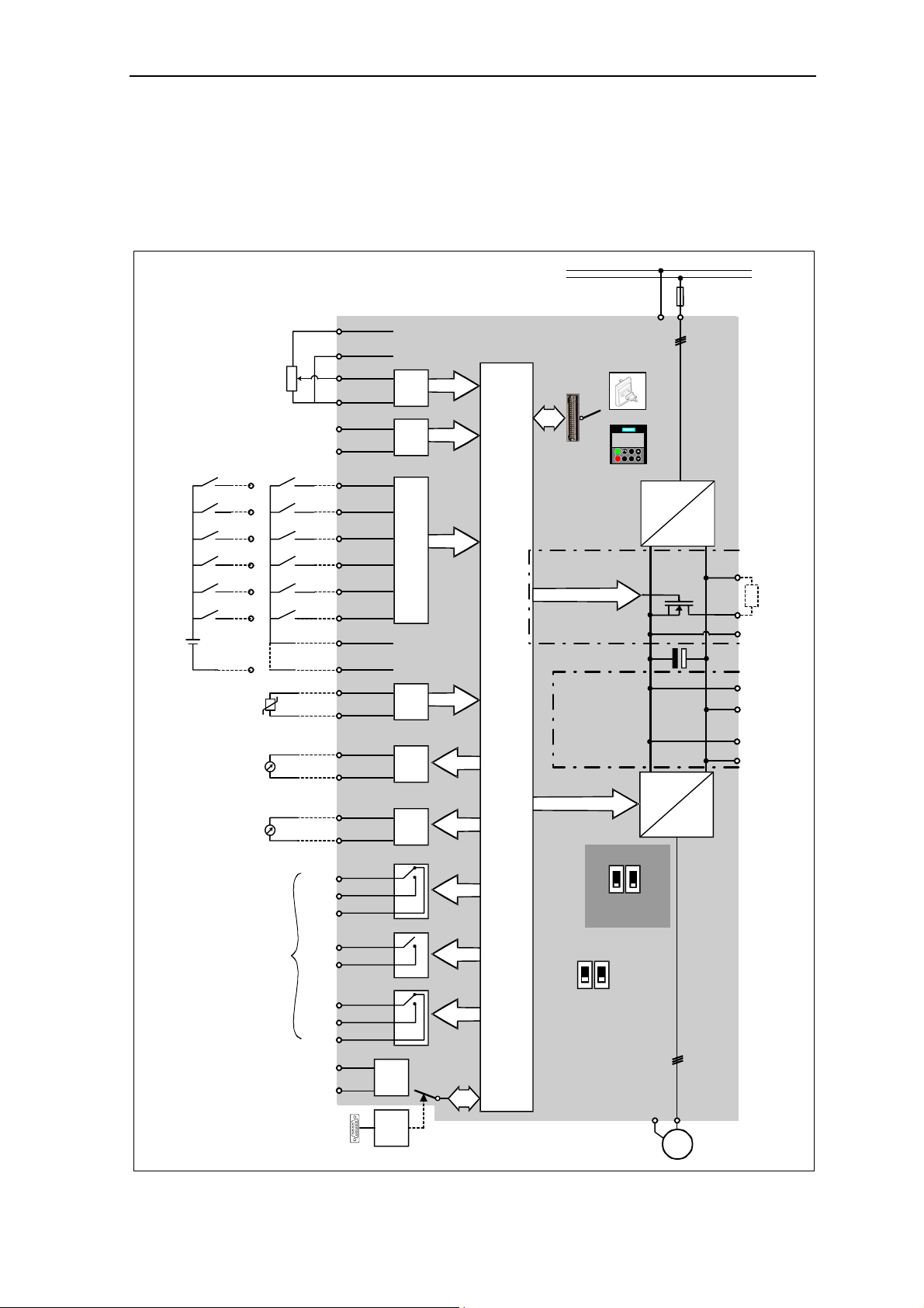
1 Block Diagram and Terminals
1.1 Block Diagram
PE
≥ 4.7 kΩ
External 24 V
DIN1
5
DIN2
6
DIN3
7
DIN4
8
DIN5
16
DIN6
Motor
PTC
KTY84
0 - 20 mA
max. 500 Ω
0 - 20 mA
max. 500 Ω
17
PNP
or
NPN
28
+
24 V
_
30 V DC / 5 A (resistive)
250 V AC / 2 A (inductive)
Relay1
Relay2
Relay3
1
2
3
4
10
11
5
6
7
8
16
17
9
28
14
15
12
13
26
27
20
19
18
22
21
25
24
23
29
30
ADC1+
ADC1-
ADC2+
ADC2-
DIN1
DIN2
DIN3
DIN4
DIN5
DIN6
PTCA
PTCB
DAC1+
DAC1-
DAC2+
DAC2-
COM
NO
NC
COM
NO
COM
NO
NC
P+
N-
+10 V
0 V
Output +24 V
max. 100 mA
(isolated)
Output 0 V
max. 100 mA
(isolated)
RS485
CB
Option
A/D
A/D
Opto Isolation
A/D
D/A
D/A
COM link
automatic
CPU
1/3 AC 200 - 240 V
3 AC 380 - 480 V
3 AC 500 - 600 V
BOP link
Frame sizes
A to F
Frame sizes
FX and GX
ADC1ADC
0 - 20 mA
current
0 - 10 V
voltage
12
RS232
150.00
Hz
Fn
I
Jog
P
0
BOP/AOP
Not
used
12
DIP switch
(on Control Board)
2
DIP switch
(on I/O Board)
=
60 Hz
50 Hz
PE
PE
~
SI
L/L1, N/L2
or
L/L1, N/L2,L3
or
L1, L2, L3
=
3 ~
U,V,W
M
DC-
DCNA
DCPA
DCNS
DCPS
B+/DC+
B-
R
External braking
Connection for
module connection
dv/dt filter
MICROMASTER 440 Parameter List
6SE6400-5BB00-0BP0
7
Page 8
Block Diagram and Terminals Issue 01/06
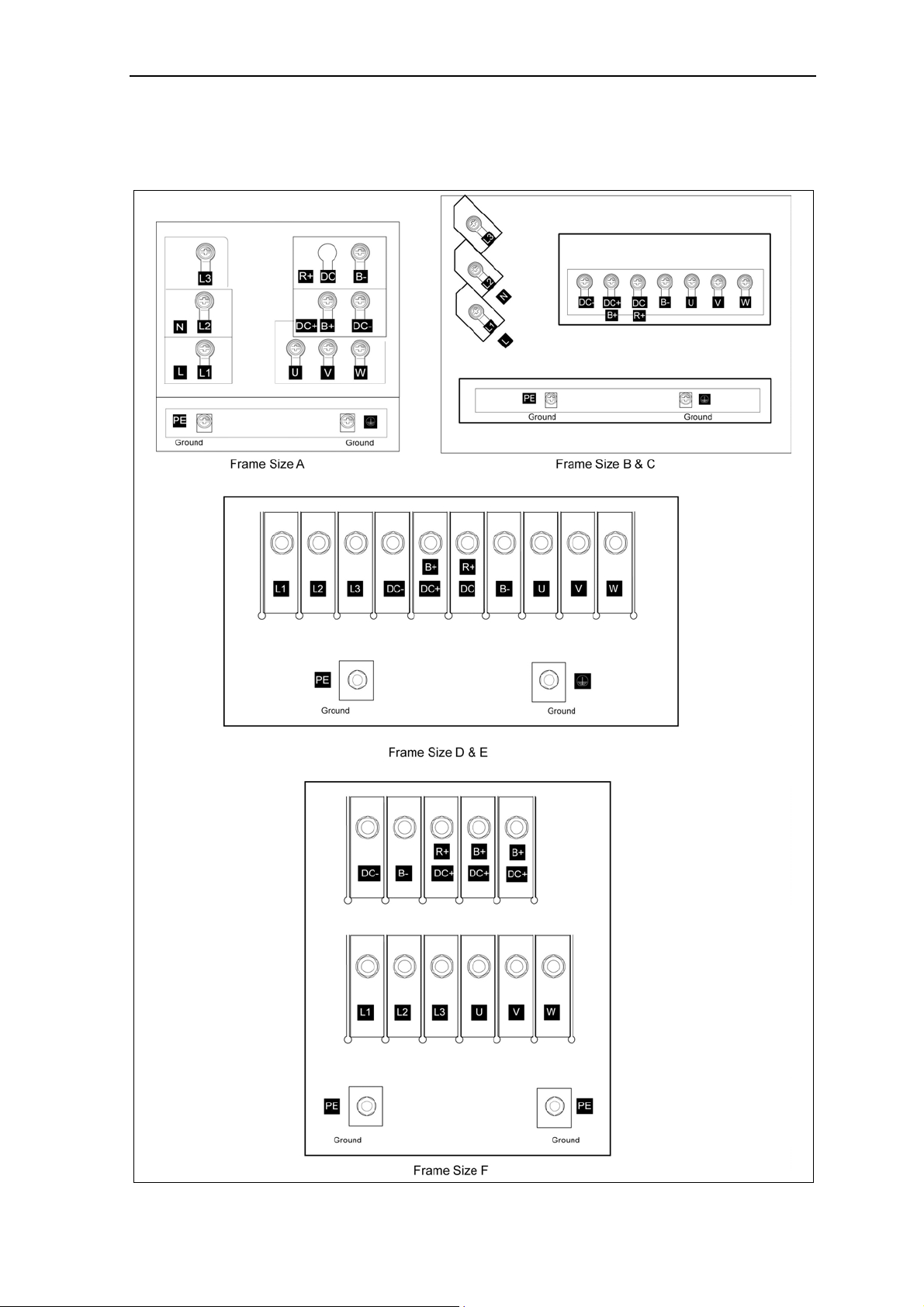
1.2 Power Terminals
You can gain access to the mains and motor terminals by removing the front covers.
Fig. 1-1 Frame Size A - F
MICROMASTER 440 Parameter List
8 6SE6400-5BB00-0BP0
Page 9
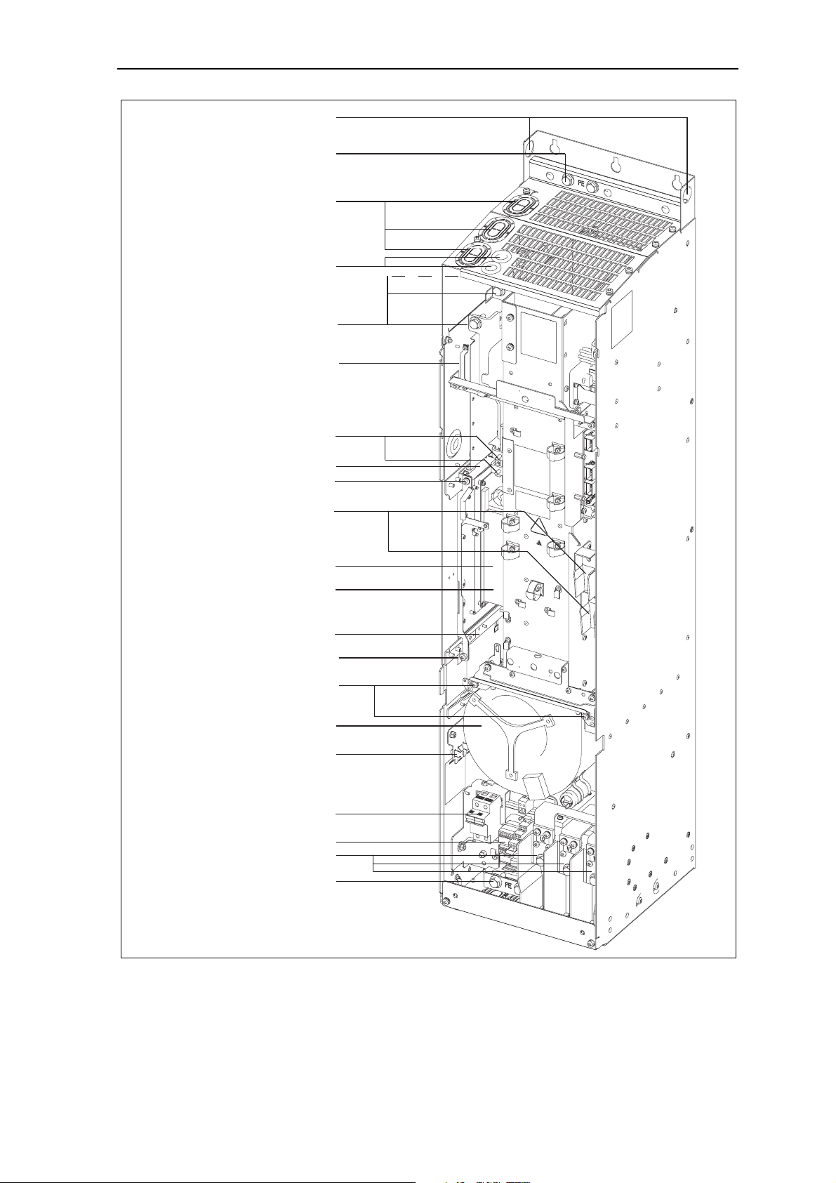
Issue 01/06 Block Diagram and Terminals
Hoisting eyes
Shield connection
Mains cable PE
Cable opening for
mains conection
U1/L1, V1/L2, W1/L3
Cable opening DCPA, DCNA
for connection of an
external braking unit
Mains cable
Phase U1/L1, V1/L2, W1/L3
Connection to
Y-Capacitor
Connection DCPA, DCNA
for external braking unit
Top adjustment rail
Top retaining screw
Connection for dv/dt filter
DCPS, DCNS
Status Display Panel
Elektronic box
Bottom adjustment rail
Bottom retaining screw
Shield connection
control leads
Transformer adaption
Motor cable
Phase U2, V2, W2
Motor cable
PE Shield connection
Fig. 1-2 Frame Size FX
Fan screws
Fan
Fan fuses
MICROMASTER 440 Parameter List
6SE6400-5BB00-0BP0
9
Page 10
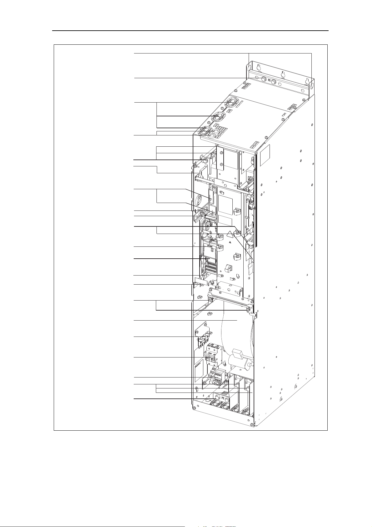
Block Diagram and Terminals Issue 01/06
Hoisting eyes
Shield connection
Mains cable PE
Cable opening for
mains conection
U1/L1, V1/L2, W1/L3
able opening DCPA, DCNA
for connection of an
external braking unit
Phase U1/L1, V1/L2, W1/L3
Connection DCPA, DCNA
for external braking unit
Connection for dv/dt filter
Status Display Panel
Bottom adjustment rail
Bottom retaining screw
Mains cable
Connection to
Y-Capacitor
Top adjustment rail
Top retaining screw
DCPS, DCNS
Elektronic box
Fan screws
Fan
Shield connection
control leads
Fan fuses
Transformer adaption
Motor cable
Phase U2, V2, W2
PE Shield connection
Motor cable
Fig. 1-3 Frame Size GX
MICROMASTER 440 Parameter List
10 6SE6400-5BB00-0BP0
Page 11
Issue 01/06 Block Diagram and Terminals
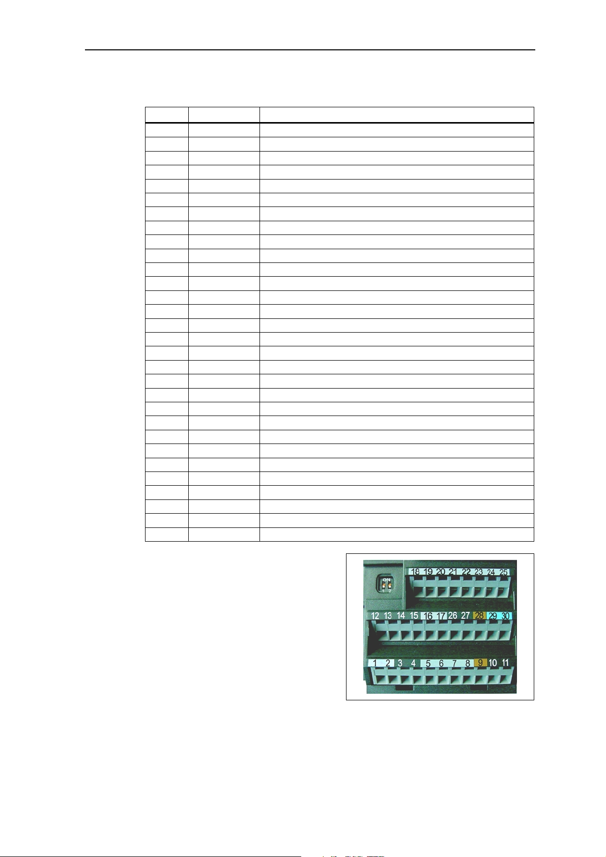
1.3 Control Terminals
Terminal Designation Function
1 - Output +10 V
2 - Output 0 V
3 ADC1+ Analog input 1 (+)
4 ADC1- Analog input 1 (-)
5 DIN1 Digital input 1
6 DIN2 Digital input 2
7 DIN3 Digital input 3
8 DIN4 Digital input 4
9 - Isolated output +24 V / max. 100 mA
10 ADC2+ Analog input 2 (+)
11 ADC2- Analog input 2 (-)
12 DAC1+ Analog output 1 (+)
13 DAC1- Analog output 1 (-)
14 PTCA Connection for PTC / KTY84
15 PTCB Connection for PTC / KTY84
16 DIN5 Digital input 5
17 DIN6 Digital input 6
18 DOUT1/NC Digital output 1 / NC contact
19 DOUT1/NO Digital output 1 / NO contact
20 DOUT1/COM Digital output 1 / Changeover contact
21 DOUT2/NO Digital output 2 / NO contact
22 DOUT2/COM Digital output 2 / Changeover contact
23 DOUT3/NC Digital output 3 / NC contact
24 DOUT3/NO Digital output 3 / NO contact
25 DOUT3/COM Digital output 3 / Changeover contact
26 DAC2+ Analog output 2 (+)
27 DAC2- Analog output 2 (-)
28 - Isolated output 0 V / max. 100 mA
29 P+ RS485 port
30 P- RS485 port
Fig. 1-4 Control terminals of
MICROMASTER 440
MICROMASTER 440 Parameter List
6SE6400-5BB00-0BP0
11
Page 12

Parameters Issue 01/06
2 Parameters
2.1 Introduction to MICROMASTER System Parameters
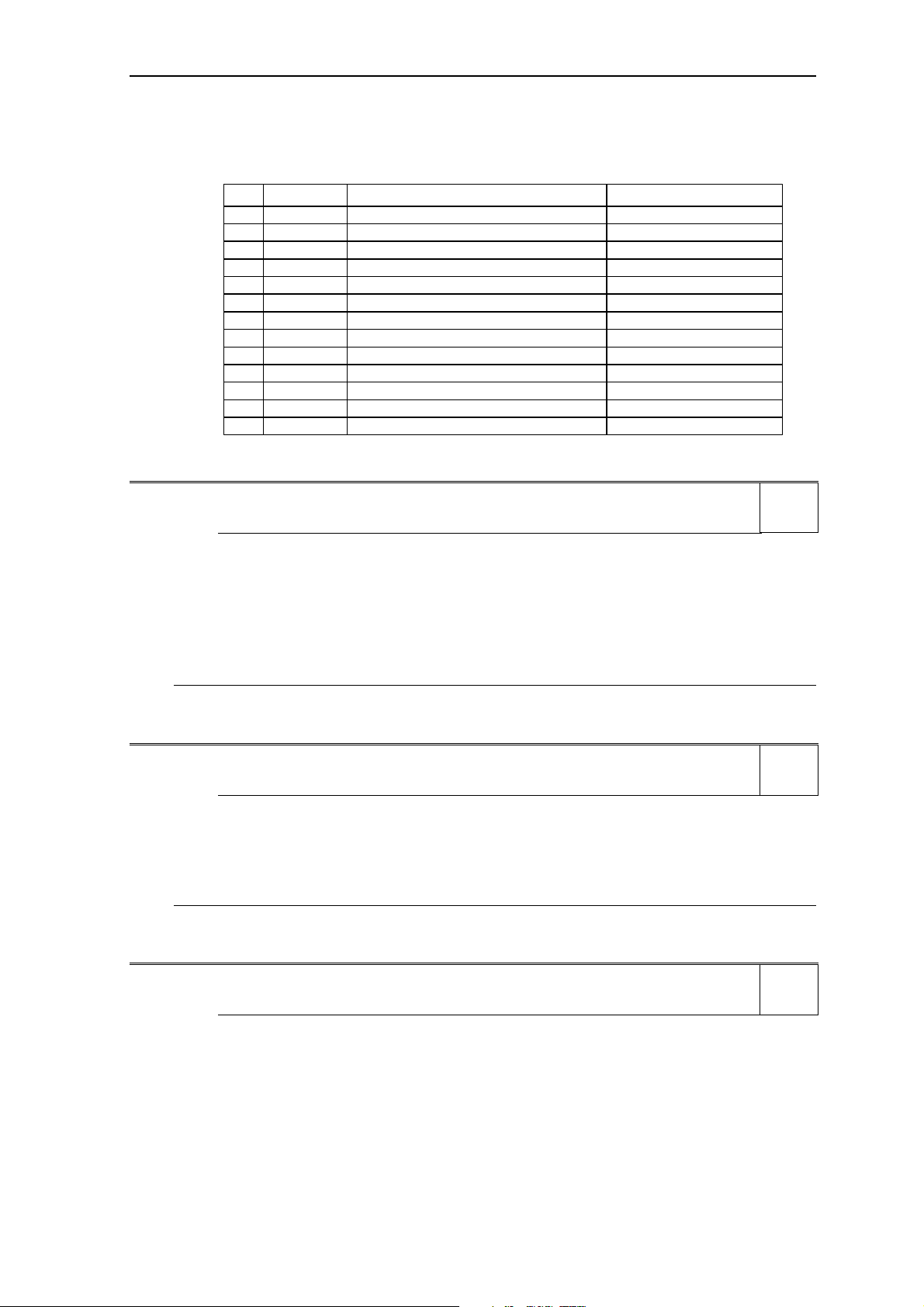
The layout of the parameter description is as follows.
1 Par number 2 Parameter name 9 Min:
[index] 3 CStat: 5 Datatype 7 Unit: 10 Def:
4 P-Group: 6 active: 8 Quick Comm: 11 Max:
13 Description:
1. Parameter number
Indicates the relevant parameter number. The numbers used are 4-digit numbers
in the range 0000 to 9999. Numbers prefixed with an “r” indicate that the
parameter is a “read-only” parameter, which displays a particular value but cannot
be changed directly by specifying a different value via this parameter number (in
such cases, dashes “-“ are entered at the points “Unit”, “Min”, “Def” and “Max” in
the header of the parameter description.
All other parameters are prefixed with a “P”. The values of these parameters can
be changed directly in the range indicated by the “Min” and “Max” settings in the
header.
[index] indicates that the parameter is an indexed parameter and specifies the
number of indices available.
2. Parameter name
Indicates the name of the relevant parameter.
Certain parameter names include the following abbreviated prefixes: BI, BO, CI,
and CO followed by a colon.
These abbreviations have the following meanings:
BI =
P9999
Binector input, i.e. parameter selects the source of a binary
(0)
signal
12 Level:
2
BO =
CI =
CO =
r9999
r9999
(999:9)
r9999 [99]
Binector output, i.e. parameter connects as a binary signal
Connector input, i.e. parameter selects the source of an
analog signal
Connector output, i.e. parameter connects as an analog
signal
CO/BO =
r9999
r9999
Connector/Binector output, i.e. parameter connects as an
analog signal and/or as a binary signal
To make use of BiCo you will need access to the full parameter list. At this level
many new parameter settings are possible, including BiCo functionality. BiCo
functionality is a different, more flexible way of setting and combining input and
output functions. It can be used in most cases in conjunction with the simple,
level 2 settings.
The BiCo system allows complex functions to be programmed. Boolean and
mathematical relationships can be set up between inputs (digital, analog, serial
etc.) and outputs (inverter current, frequency, analog output, relays, etc.).
MICROMASTER 440 Parameter List
12 6SE6400-5BB00-0BP0
Page 13

Issue 01/06 Parameters
3. CStat
Commissioning status of the parameter. Three states are possible:
Commissioning C
Run U
Ready to run T
This indicates when the parameter can be changed. One, two or all three states
may be specified. If all three states are specified, this means that it is possible to
change this parameter setting in all three inverter states
4. P-Group
Indicates the functional group of the particular.
Note
Parameter P0004 (parameter filter) acts as a filter and focuses access to
parameters according to the functional group selected.
5. Datatype
The data types available are shown in the table below.
Notation Meaning
U16 16-bit unsigned
U32 32-bit unsigned
I16 16-bit integer
I32 32-bit integer
Float Floating point
6. Active
Indicates whether
♦ Immediately changes to the parameter values take effective immediately after
they have been entered, or
♦ Confirm the “P” button on the operator panel (BOP or AOP) must be
pressed before the changes take effect.
7. Unit
Indicates the unit of measure applicable to the parameter values
8. QuickComm
Indicates whether or not (Yes or No) a parameter can only be changed during
quick commissioning, i.e. when P0010 (parameter groups for commissioning) is
set to 1 (quick commissioning).
9. Min
Indicates the minimum value to which the parameter can be set.
10. Def
Indicates the default value, i.e. the value which applies if the user does not specify
a particular value for the parameter.
11. Max
Indicates the maximum value to which the parameter can be set.
12. Level
Indicates the level of user access. There are four access levels: Standard,
Extended, Expert and Service. The number of parameters that appear in each
functional group depends on the access level set in P0003 (user access level).
MICROMASTER 440 Parameter List
6SE6400-5BB00-0BP0
13
Page 14

Parameters Issue 01/06
13. Description
The parameter description consists of the sections and contents listed below.
Some of these sections and contents are optional and will be omitted on a caseto-case basis if not applicable.
Description: Brief explanation of the parameter function.
Diagram: Where applicable, diagram to illustrate the effects of parameters on a
Settings: List of applicable settings. These include
Example: Optional example of the effects of a particular parameter setting.
Dependency: Any conditions that must be satisfied in connection with this parameter. Also
Warning / Caution / Notice / Note:
More details: Any sources of more detailed information concerning the particular parameter.
characteristic curve, for example
Possible settings, Most common settings, Index and Bitfields
any particular effects, which this parameter has on other parameter(s) or which
other parameters have on this one.
Important information which must be heeded to prevent personal injury or
damage to equipment / specific information which should be heeded in order to
avoid problems / information which may be helpful to the user
Operators
The following operators are used in the parameter list to represent mathematical
interrelationships:
Arithmetic operators
+ Addition
- Subtraction
* Multiplication
/ Division
Comparison operators
> Greater than
>= Greater than / equal to
< Less than
<= Less than / equal to
Equivalence operators
== Equal to
!= Not equal to
Logical operators
&& AND logic operation
|| OR logic operation
MICROMASTER 440 Parameter List
14 6SE6400-5BB00-0BP0
Page 15

Issue 01/06 Parameters
2.2 Quick commissioning (P0010 = 1)
The following parameters are necessary for quick commissioning (P0010 = 1).
Quick commissioning (P0010 = 1)
Par.-No. Name Access level Cstat
P0100 Europe / North America 1 C
P0205 Inverter application 3 C
P0300 Select motor type 2 C
P0304 Motor voltage rating 1 C
P0305 Motor current rating 1 C
P0307 Motor power rating 1 C
P0308 Motor cosPhi rating 1 C
P0309 Motor efficiency rating 1 C
P0310 Motor frequency rating 1 C
P0311 Motor speed rating 1 C
P0320 Motor magnetizing current 3 CT
P0335 Motor cooling 2 CT
P0640 Motor overload factor [%] 2 CUT
P0700 Selection of command source 1 CT
P1000 Selection of frequency setpoint 1 CT
P1080 Min. speed 1 CUT
P1082 Max. speed 1 CT
P1120 Ramp-up time 1 CUT
P1121 Ramp-down time 1 CUT
P1135 OFF3 ramp-down time 2 CUT
P1300 Control mode 2 CT
P1500 Selection of torque setpoint 2 CT
P1910 Select motor data identification 2 CT
P1960 Speed control optimisation 3 CT
P3900 End of quick commissioning 1 C
When P0010 = 1 is chosen, P0003 (user access level) can be used to select the
parameters to be accessed. This parameter also allows selection of a user-defined
parameter list for quick commissioning.
At the end of the quick commissioning sequence, set P3900 = 1 to carry out the
necessary motor calculations and clear all other parameters (not included in P0010
= 1) to their default settings.
Note
This applies only in Quick Commissioning mode.
Reset to Factory default
To reset all parameters to the factory default settings; the following parameters should
be set as follows:
Set P0010 = 30
Set P0970 = 1
Note
The reset process takes approximately 10 seconds to complete. Reset to Factory
default
MICROMASTER 440 Parameter List
6SE6400-5BB00-0BP0
15
Page 16

Parameters Issue 01/06
Seven-segment display
The seven-segment display is structured as follows:
9 811 1013 1215 14Segment Bit
Segment Bit
1 03 25 47 6
The significance of the relevant bits in the display is described in the status and
control word parameters.
MICROMASTER 440 Parameter List
16 6SE6400-5BB00-0BP0
Page 17

Issue 01/06 Parameters
2.3 Command and Drive Datasets - Overview
Command Datasets (CDS)
ParNo Parameter text 1)
P0700[3] Selection of command source X
P0701[3] Function of digital input 1 X
P0702[3] Function of digital input 2 X
P0703[3] Function of digital input 3 X
P0704[3] Function of digital input 4 X
P0705[3] Function of digital input 5 X
P0706[3] Function of digital input 6 X
P0707[3] Function of digital input 7 X
P0708[3] Function of digital input 8 X
P0719[3] Selection of cmd. & freq. setp. X
P0731[3] BI: Function of digital output 1 X
P0732[3] BI: Function of digital output 2 X
P0733[3] BI: Function of digital output 3 X
P0800[3] BI: Download parameter set 0 –
P0801[3] BI: Download parameter set 1 –
P0840[3] BI: ON/OFF1 X
P0842[3] BI: ON reverse/OFF1 X
P0844[3] BI: 1. OFF2 X
P0845[3] BI: 2. OFF2 X
P0848[3] BI: 1. OFF3 X
P0849[3] BI: 2. OFF3 X
P0852[3] BI: Pulse enable X
P1000[3] Selection of frequency setpoint X
P1020[3] BI: Fixed freq. selection Bit 0 X
P1021[3] BI: Fixed freq. selection Bit 1 X
P1022[3] BI: Fixed freq. selection Bit 2 X
P1023[3] BI: Fixed freq. selection Bit 3 X
P1026[3] BI: Fixed freq. selection Bit 4 X
P1028[3] BI: Fixed freq. selection Bit 5 X
P1035[3] BI: Enable MOP (UP-command) X
P1036[3] BI: Enable MOP (DOWN-command) X
P1055[3] BI: Enable JOG right X
P1056[3] BI: Enable JOG left X
P1070[3] CI: Main setpoint X
P1071[3] CI: Main setpoint scaling X
ParNo Parameter text 1)
P1074[3] BI: Disable additional setpoint X
P1075[3] CI: Additional setpoint X
P1076[3] CI: Additional setpoint scaling X
P1110[3] BI: Inhibit neg. freq. setpoint X
P1113[3] BI: Reverse X
P1124[3] BI: Enable JOG ramp times X
P1140[3] BI: RFG enable X
P1141[3] BI: RFG start X
P1142[3] BI: RFG enable setpoint X
P1230[3] BI: Enable DC braking X
P1330[3] CI: Voltage setpoint X
P1477[3] BI: Set integrator of n-ctrl. X
P1478[3] CI: Set integrator value n-ctrl. X
P1500[3] Selection of torque setpoint X
P1501[3] BI: Change to torque control X
P1503[3] CI: Torque setpoint X
P1511[3] CI: Additional torque setpoint X
P1522[3] CI: Upper torque limit –
P1523[3] CI: Lower torque limit –
P2103[3] BI: 1. Faults acknowledgement X
P2104[3] BI: 2. Faults acknowledgement X
P2106[3] BI: External fault X
P2200[3] BI: Enable PID controller –
P2220[3] BI: Fixed PID setp. select Bit 0 X
P2221[3] BI: Fixed PID setp. select Bit 1 X
P2222[3] BI: Fixed PID setp. select Bit 2 X
P2223[3] BI: Fixed PID setp. select Bit 3 X
P2226[3] BI: Fixed PID setp. select Bit 4 X
P2228[3] BI: Fixed PID setp. select Bit 5 X
P2235[3] BI: Enable PID-MOP (UP-cmd) X
P2236[3] BI: Enable PID-MOP (DOWN-cmd) X
P2253[3] CI: PID setpoint X
P2254[3] CI: PID trim source X
P2264[3] CI: PID feedback X
1) X = Parameters will be altered during data set
– = Parameters will be altered in the state "Ready" only
switchover (CDS) in the state "Run"
MICROMASTER 440 Parameter List
6SE6400-5BB00-0BP0
17
Page 18

Parameters Issue 01/06
Drive Datasets (DDS)
ParNo Parameter text
P0005[3] Display selection
r0035[3] CO: Act. motor temperature
P0291[3] Inverter protection
P0300[3] Select motor type
P0304[3] Rated motor voltage
P0305[3] Rated motor current
P0307[3] Rated motor power
P0308[3] Rated motor cosPhi
P0309[3] Rated motor efficiency
P0310[3] Rated motor frequency
P0311[3] Rated motor speed
r0313[3] Motor pole pairs
P0314[3] Motor pole pair number
P0320[3] Motor magnetizing current
r0330[3] Rated motor slip
r0331[3] Rated magnetization current
r0332[3] Rated power factor
r0333[3] Rated motor torque
P0335[3] Motor cooling
P0340[3] Calculation of motor parameters
P0341[3] Motor inertia [kg*m^2]
P0342[3] Total/motor inertia ratio
P0344[3] Motor weight
r0345[3] Motor start-up time
P0346[3] Magnetization time
P0347[3] Demagnetization time
P0350[3] Stator resistance (line-to-line)
P0352[3] Cable resistance
P0354[3] Rotor resistance
P0356[3] Stator leakage inductance
P0358[3] Rotor leakage inductance
P0360[3] Main inductance
P0362[3] Magnetizing curve flux 1
P0363[3] Magnetizing curve flux 2
P0364[3] Magnetizing curve flux 3
P0365[3] Magnetizing curve flux 4
P0366[3] Magnetizing curve imag 1
P0367[3] Magnetizing curve imag 2
P0368[3] Magnetizing curve imag 3
P0369[3] Magnetizing curve imag 4
ParNo Parameter text
r0370[3] Stator resistance [%]
r0372[3] Cable resistance [%]
r0373[3] Rated stator resistance [%]
r0374[3] Rotor resistance [%]
r0376[3] Rated rotor resistance [%]
r0377[3] Total leakage reactance [%]
r0382[3] Main reactance [%]
r0384[3] Rotor time constant
r0386[3] Total leakage time constant
P0400[3] Select encoder type
P0408[3] Encoder pulses per revolution
P0491[3] Reaction on freq. signal loss
P0492[3] Allowed frequency difference
P0494[3] Delay frequency loss reaction
P0500[3] Technological application
P0530[3] Unit for positioning signal
P0531[3] Unit conversion
P0601[3] Motor temperature sensor
P0604[3] Threshold motor temperature
P0625[3] Ambient motor temperature
P0626[3] Overtemperature stator iron
P0627[3] Overtemperature stator winding
P0628[3] Overtemperature rotor winding
r0630[3] CO: Ambient temperature
r0631[3] CO: Stator iron temperature
r0632[3] CO: Stator winding temperature
r0633[3] CO: Rotor winding temperature
P0640[3] Motor overload factor [%]
P1001[3] Fixed frequency 1
P1002[3] Fixed frequency 2
P1003[3] Fixed frequency 3
P1004[3] Fixed frequency 4
P1005[3] Fixed frequency 5
P1006[3] Fixed frequency 6
P1007[3] Fixed frequency 7
P1008[3] Fixed frequency 8
P1009[3] Fixed frequency 9
P1010[3] Fixed frequency 10
P1011[3] Fixed frequency 11
P1012[3] Fixed frequency 12
MICROMASTER 440 Parameter List
18 6SE6400-5BB00-0BP0
Page 19

Issue 01/06 Parameters
ParNo Parameter text
P1013[3] Fixed frequency 13
P1014[3] Fixed frequency 14
P1015[3] Fixed frequency 15
P1031[3] Setpoint memory of the MOP
P1040[3] Setpoint of the MOP
P1058[3] JOG frequency right
P1059[3] JOG frequency left
P1060[3] JOG ramp-up time
P1061[3] JOG ramp-down time
P1080[3] Min. frequency
P1082[3] Max. frequency
P1091[3] Skip frequency 1
P1092[3] Skip frequency 2
P1093[3] Skip frequency 3
P1094[3] Skip frequency 4
P1101[3] Skip frequency bandwidth
P1120[3] Ramp-up time
P1121[3] Ramp-down time
P1130[3] Ramp-up initial rounding time
P1131[3] Ramp-up final rounding time
P1132[3] Ramp-down initial rounding time
P1133[3] Ramp-down final rounding time
P1134[3] Rounding type
P1135[3] OFF3 ramp-down time
P1202[3] Motor-current: Flying start
P1203[3] Search rate: Flying start
P1232[3] DC braking current
P1233[3] Duration of DC braking
P1234[3] DC braking start frequency
P1236[3] Compound braking current
P1240[3] Configuration of Vdc controller
P1243[3] Dynamic factor of Vdc-max
P1245[3] Switch on level kin. buffering
r1246[3] CO:Switch-on level kin buffering
P1247[3] Dyn. factor of kinetic buffering
P1250[3] Gain of Vdc-controller
P1251[3] Integration time Vdc-controller
P1252[3] Differential time Vdc-controller
P1253[3] Vdc-controller output limitation
P1256[3] Reaction of kinetic buffering
ParNo Parameter text
P1257[3] Freq limit for kinetic buffering
P1300[3] Control mode
P1310[3] Continuous boost
P1311[3] Acceleration boost
P1312[3] Starting boost
P1316[3] Boost end frequency
P1320[3] Programmable V/f freq. coord. 1
P1321[3] Programmable V/f volt. coord. 1
P1322[3] Programmable V/f freq. coord. 2
P1323[3] Programmable V/f volt. coord. 2
P1324[3] Programmable V/f freq. coord. 3
P1325[3] Programmable V/f volt. coord. 3
P1333[3] Start frequency for FCC
P1335[3] Slip compensation
P1336[3] Slip limit
P1338[3] Resonance damping gain V/f
P1340[3] Imax freq. controller prop. gain
P1341[3] Imax freq. ctrl. integral time
P1345[3] Imax voltage ctrl. prop. gain
P1346[3] Imax voltage ctrl. integral time
P1350[3] Voltage soft start
P1400[3] Configuration of speed control
P1442[3] Filter time for act. speed
P1452[3] Filter time for act. freq (SLVC)
P1460[3] Gain speed controller
P1462[3] Integral time speed controller
P1470[3] Gain speed controller (SLVC)
P1472[3] Integral time n-ctrl. (SLVC)
P1488[3] Droop input source
P1489[3] Droop scaling
P1492[3] Enable droop
P1496[3] Scaling accel. precontrol
P1499[3] Scaling accel. torque control
P1520[3] CO: Upper torque limit
P1521[3] CO: Lower torque limit
P1525[3] Scaling lower torque limit
P1530[3] Motoring power limitation
P1531[3] Regenerative power limitation
P1570[3] CO: Fixed value flux setpoint
P1574[3] Dynamic voltage headroom
MICROMASTER 440 Parameter List
6SE6400-5BB00-0BP0
19
Page 20

Parameters Issue 01/06
ParNo Parameter text
P1580[3] Efficiency optimization
P1582[3] Smooth time for flux setpoint
P1596[3] Int. time field weak. controller
P1610[3] Continuous torque boost (SLVC)
P1611[3] Acc. torque boost (SLVC)
P1654[3] Smooth time for Isq setpoint
P1715[3] Gain current controller
P1717[3] Integral time current controller
P1745[3] Variance flux error
P1750[3] Control word of motor model
P1755[3] Start-freq. motor model (SLVC)
P1756[3] Hyst.-freq. motor model (SLVC)
P1758[3] Chng-ov. del. t SLVC op.-lp ctrl
P1759[3] Chng-ov. del. t SLVC cl.-lp ctrl
P1764[3] Kp of n-adaption (SLVC)
P1767[3] Tn of n-adaption (SLVC)
P1780[3] Control word of Rs/Rr-adaption
P1781[3] Tn of Rs-adaption
P1786[3] Tn of Xm-adaption
P1803[3] Max. modulation
P1820[3] Reverse output phase sequence
P1909[3] Ctrl. word of motor data ident.
P2000[3] Reference frequency
P2001[3] Reference voltage
P2002[3] Reference current
P2003[3] Reference torque
P2004[3] Reference power
P2150[3] Hysteresis frequency f_hys
P2153[3] Time-constant frequency filter
P2155[3] Threshold frequency f_1
P2156[3] Delay time of threshold freq f_1
P2157[3] Threshold frequency f_2
P2158[3] Delay time of threshold freq f_2
P2159[3] Threshold frequency f_3
P2160[3] Delay time of threshold freq f_3
P2161[3] Min. threshold for freq. setp.
P2162[3] Hysteresis freq. for overfreq.
P2163[3] Entry freq. for perm. deviation
P2164[3] Hysteresis frequency deviation
P2165[3] Delay time permitted deviation
P2166[3] Delay time ramp up completed
P2167[3] Switch-off frequency f_off
P2168[3] Delay time T_off
ParNo Parameter text
P2170[3] Threshold current I_thresh
P2171[3] Delay time current
P2172[3] Threshold DC-link voltage
P2173[3] Delay time DC-link voltage
P2174[3] Torque threshold M_thresh
P2176[3] Delay time for torque threshold
P2177[3] Delay time for motor is blocked
P2178[3] Delay time for motor pulled out
P2181[3] Belt failure detection mode
P2182[3] Belt threshold frequency 1
P2183[3] Belt threshold frequency 2
P2184[3] Belt threshold frequency 3
P2185[3] Upper torque threshold 1
P2186[3] Lower torque threshold 1
P2187[3] Upper torque threshold 2
P2188[3] Lower torque threshold 2
P2189[3] Upper torque threshold 3
P2190[3] Lower torque threshold 3
P2192[3] Time delay for belt failure
P2201[3] Fixed PID setpoint 1
P2202[3] Fixed PID setpoint 2
P2203[3] Fixed PID setpoint 3
P2204[3] Fixed PID setpoint 4
P2205[3] Fixed PID setpoint 5
P2206[3] Fixed PID setpoint 6
P2207[3] Fixed PID setpoint 7
P2208[3] Fixed PID setpoint 8
P2209[3] Fixed PID setpoint 9
P2210[3] Fixed PID setpoint 10
P2211[3] Fixed PID setpoint 11
P2212[3] Fixed PID setpoint 12
P2213[3] Fixed PID setpoint 13
P2214[3] Fixed PID setpoint 14
P2215[3] Fixed PID setpoint 15
P2231[3] Setpoint memory of PID-MOP
P2240[3] Setpoint of PID-MOP
P2480[3] Position mode
P2481[3] Gearbox ratio input
P2482[3] Gearbox ratio output
P2484[3] No. of shaft turns = 1 Unit
P2487[3] Positional error trim value
P2488[3] Distance / No. of revolutions
MICROMASTER 440 Parameter List
20 6SE6400-5BB00-0BP0
Page 21

Issue 01/06 Parameters
2.4 Binector Input Parameters
ParNo Parameter text
P0731[3] BI: Function of digital output 1
P0732[3] BI: Function of digital output 2
P0733[3] BI: Function of digital output 3
P0800[3] BI: Download parameter set 0
P0801[3] BI: Download parameter set 1
P0810 BI: CDS bit 0 (Local / Remote)
P0811 BI: CDS bit 1
P0820 BI: DDS bit 0
P0821 BI: DDS bit 1
P0840[3] BI: ON/OFF1
P0842[3] BI: ON reverse/OFF1
P0844[3] BI: 1. OFF2
P0845[3] BI: 2. OFF2
P0848[3] BI: 1. OFF3
P0849[3] BI: 2. OFF3
P0852[3] BI: Pulse enable
P1020[3] BI: Fixed freq. selection Bit 0
P1021[3] BI: Fixed freq. selection Bit 1
P1022[3] BI: Fixed freq. selection Bit 2
P1023[3] BI: Fixed freq. selection Bit 3
P1026[3] BI: Fixed freq. selection Bit 4
P1028[3] BI: Fixed freq. selection Bit 5
P1035[3] BI: Enable MOP (UP-command)
P1036[3] BI: Enable MOP (DOWN-command)
P1055[3] BI: Enable JOG right
P1056[3] BI: Enable JOG left
P1074[3] BI: Disable additional setpoint
P1110[3] BI: Inhibit neg. freq. setpoint
P1113[3] BI: Reverse
P1124[3] BI: Enable JOG ramp times
P1140[3] BI: RFG enable
P1141[3] BI: RFG start
P1142[3] BI: RFG enable setpoint
P1230[3] BI: Enable DC braking
P1477[3] BI: Set integrator of n-ctrl.
ParNo Parameter text
P1501[3] BI: Change to torque control
P2103[3] BI: 1. Faults acknowledgement
P2104[3] BI: 2. Faults acknowledgement
P2106[3] BI: External fault
P2200[3] BI: Enable PID controller
P2220[3] BI: Fixed PID setp. select Bit 0
P2221[3] BI: Fixed PID setp. select Bit 1
P2222[3] BI: Fixed PID setp. select Bit 2
P2223[3] BI: Fixed PID setp. select Bit 3
P2226[3] BI: Fixed PID setp. select Bit 4
P2228[3] BI: Fixed PID setp. select Bit 5
P2235[3] BI: Enable PID-MOP (UP-cmd)
P2236[3] BI: Enable PID-MOP (DOWN-cmd)
P2810[2] BI: AND 1
P2812[2] BI: AND 2
P2814[2] BI: AND 3
P2816[2] BI: OR 1
P2818[2] BI: OR 2
P2820[2] BI: OR 3
P2822[2] BI: XOR 1
P2824[2] BI: XOR 2
P2826[2] BI: XOR 3
P2828 BI: NOT 1
P2830 BI: NOT 2
P2832 BI: NOT 3
P2834[4] BI: D-FF 1
P2837[4] BI: D-FF 2
P2840[2] BI: RS-FF 1
P2843[2] BI: RS-FF 2
P2846[2] BI: RS-FF 3
P2849 BI: Timer 1
P2854 BI: Timer 2
P2859 BI: Timer 3
P2864 BI: Timer 4
MICROMASTER 440 Parameter List
6SE6400-5BB00-0BP0
21
Page 22
Parameters Issue 01/06
2.5 Connector Input Parameters
ParNo Parameter text
P0095[10] CI: Display PZD signals
P0771[2] CI: DAC
P1070[3] CI: Main setpoint
P1071[3] CI: Main setpoint scaling
P1075[3] CI: Additional setpoint
P1076[3] CI: Additional setpoint scaling
P1330[3] CI: Voltage setpoint
P1478[3] CI: Set integrator value n-ctrl.
P1503[3] CI: Torque setpoint
P1511[3] CI: Additional torque setpoint
P1522[3] CI: Upper torque limit
P1523[3] CI: Lower torque limit
P2016[8] CI: PZD to BOP link (USS)
P2019[8] CI: PZD to COM link (USS)
P2051[8] CI: PZD to CB
2.6 Binector Output Parameters
ParNo Parameter text
P2253[3] CI: PID setpoint
P2254[3] CI: PID trim source
P2264[3] CI: PID feedback
P2869[2] CI: ADD 1
P2871[2] CI: ADD 2
P2873[2] CI: SUB 1
P2875[2] CI: SUB 2
P2877[2] CI: MUL 1
P2879[2] CI: MUL 2
P2881[2] CI: DIV 1
P2883[2] CI: DIV 2
P2885[2] CI: CMP 1
P2887[2] CI: CMP 2
ParNo Parameter text
r0751 BO: Status word of ADC
r2032 BO: CtrlWrd1 from BOP link (USS)
r2033 BO: CtrlWrd2 from BOP link (USS)
r2036 BO: CtrlWrd1 from COM link (USS)
r2037 BO: CtrlWrd2 from COM link (USS)
r2090 BO: Control word 1 from CB
r2091 BO: Control word 2 from CB
r2811 BO: AND 1
r2813 BO: AND 2
r2815 BO: AND 3
r2817 BO: OR 1
r2819 BO: OR 2
r2821 BO: OR 3
r2823 BO: XOR 1
r2825 BO: XOR 2
r2827 BO: XOR 3
r2829 BO: NOT 1
r2831 BO: NOT 2
r2833 BO: NOT 3
r2835 BO: Q D-FF 1
ParNo Parameter text
r2836 BO: NOT-Q D-FF 1
r2838 BO: Q D-FF 2
r2839 BO: NOT-Q D-FF 2
r2841 BO: Q RS-FF 1
r2842 BO: NOT-Q RS-FF 1
r2844 BO: Q RS-FF 2
r2845 BO: NOT-Q RS-FF 2
r2847 BO: Q RS-FF 3
r2848 BO: NOT-Q RS-FF 3
r2852 BO: Timer 1
r2853 BO: Nout timer 1
r2857 BO: Timer 2
r2858 BO: Nout timer 2
r2862 BO: Timer 3
r2863 BO: Nout timer 3
r2867 BO: Timer 4
r2868 BO: Nout timer 4
r2886 BO: CMP 1
r2888 BO: CMP 2
MICROMASTER 440 Parameter List
22 6SE6400-5BB00-0BP0
Page 23

Issue 01/06 Parameters
2.7 Connector Output Parameters
ParNo Parameter text
r0020 CO: Freq. setpoint before RFG
r0021 CO: Act. filtered frequency
r0024 CO: Act. filtered output freq.
r0025 CO: Act. filtered output voltage
r0026 CO: Act. filtered DC-link volt.
r0027 CO: Act. filtered output current
r0029 CO: Flux gen. current
r0030 CO: Torque gen. current
r0031 CO: Act. filtered torque
r0032 CO: Act. filtered power
r0035[3] CO: Act. motor temperature
r0036 CO:Inverter overload utilization
r0037[5] CO: Inverter temperature [°C]
r0038 CO: Act. power factor
r0039 CO: Energy consumpt. meter [kWh]
r0050 CO: Active command data set
r0051[2] CO: Active drive data set (DDS)
r0061 CO: Act. encoder frequency
r0062 CO: Freq. setpoint
r0063 CO: Act. frequency
r0064 CO: Dev. frequency controller
r0065 CO: Slip frequency
r0066 CO: Act. output frequency
r0067 CO: Act. output current limit
r0068 CO: Output current
r0069[6] CO: Act. phase currents
r0070 CO: Act. DC-link voltage
r0071 CO: Max. output voltage
r0072 CO: Act. output voltage
r0074 CO: Act. modulation
r0075 CO: Current setpoint Isd
r0076 CO: Act. current Isd
r0077 CO: Current setpoint Isq
r0078 CO: Act. current Isq
r0079 CO: Torque setpoint (total)
r0080 CO: Act. torque
r0084 CO: Act. air gap flux
r0086 CO: Act. active current
r0090 CO: Act. rotor angle
r0394 CO: Stator resistance IGBT [%]
ParNo Parameter text
r0395 CO: Total stator resistance [%]
r0396 CO: Act. rotor resistance
r0630[3] CO: Ambient temperature
r0631[3] CO: Stator iron temperature
r0632[3] CO: Stator winding temperature
r0633[3] CO: Rotor winding temperature
r0755[2] CO: Act. ADC after scal. [4000h]
r0947[8] CO: Letzte Fehlermeldung
r0948[12] CO: Fehlerzeit
r0949[8] CO: Fehlerwert
r1024 CO: Act. fixed frequency
r1050 CO: Act. Output freq. of the MOP
r1078 CO: Total frequency setpoint
r1079 CO: Selected frequency setpoint
r1114 CO: Freq. setp. after dir. ctrl.
r1119 CO: Freq. setpoint before RFG
r1170 CO: Frequency setpoint after RFG
r1242 CO: Switch-on level of Vdc-max
r1246[3] CO:Switch-on level kin buffering
r1315 CO: Total boost voltage
r1337 CO: V/f slip frequency
r1343 CO: Imax controller freq. output
r1344 CO: Imax controller volt. output
r1438 CO: Freq. setpoint to controller
r1445 CO: Act. filtered frequency
r1482 CO: Integral output of n-ctrl.
r1490 CO: Droop frequency
r1508 CO: Torque setpoint
r1515 CO: Additional torque setpoint
r1518 CO: Acceleration torque
P1520[3] CO: Upper torque limit
P1521[3] CO: Lower torque limit
r1526 CO: Upper torque limitation
r1527 CO: Lower torque limitation
r1536 CO: Max. trq. motoring current
r1537 CO: Max trq regenerative current
r1538 CO: Upper torque limit (total)
r1539 CO: Lower torque limit (total)
P1570[3] CO: Fixed value flux setpoint
r1583 CO: Flux setpoint (smoothed)
MICROMASTER 440 Parameter List
6SE6400-5BB00-0BP0
23
Page 24

Parameters Issue 01/06
ParNo Parameter text
r1597 CO: Outp. field weak. controller
r1598 CO: Flux setpoint (total)
r1718 CO: Output of Isq controller
r1719 CO: Integral output of Isq ctrl.
r1723 CO: Output of Isd controller
r1724 CO: Integral output of Isd ctrl.
r1725 CO: Integral limit of Isd ctrl.
r1728 CO: Decoupling voltage
r1770 CO: Prop. output of n-adaption
r1746 CO: Flussabweichung
r1771 CO: Int. output of n-adaption
r1778 CO: Flux angle difference
r1801 CO: Act. pulse frequency
r2015[8] CO: PZD from BOP link (USS)
r2018[8] CO: PZD from COM link (USS)
ParNo Parameter text
r2050[8] CO: PZD from CB
r2169 CO: Act. filtered frequency
r2224 CO: Act. fixed PID setpoint
r2250 CO: Output setpoint of PID-MOP
r2260 CO: PID setpoint after PID-RFG
r2262 CO: Filtered PID setp. after RFG
r2266 CO: PID filtered feedback
r2272 CO: PID scaled feedback
r2273 CO: PID error
r2294 CO: Act. PID output
r2870 CO: ADD 1
r2872 CO: ADD 2
r2874 CO: SUB 1
r2876 CO: SUB 2
r2878 CO: MUL 1
r2880 CO: MUL 2
r2882 CO: DIV 1
r2884 CO: DIV 2
P2889 CO: Fixed setpoint 1 in [%]
P2890 CO: Fixed setpoint 2 in [%]
2.8 Connector/Binector Output Parameters
ParNo Parameter text
r0019 CO/BO: BOP control word
r0052 CO/BO: Act. status word 1
r0053 CO/BO: Act. status word 2
r0054 CO/BO: Act. control word 1
r0055 CO/BO: Act. control word 2
ParNo Parameter text
r0056 CO/BO: Status of motor control
r0403 CO/BO: Encoder status word
r0722 CO/BO: Binary input values
r0747 CO/BO: State of digital outputs
r0785 CO/BO: Zustand Analogausgang
r1407 CO/BO: Status 2 of motor control
r2197 CO/BO: Monitoring word 1
r2198 CO/BO: Monitoring word 2
MICROMASTER 440 Parameter List
24 6SE6400-5BB00-0BP0
Page 25

Issue 01/06 Parameter Description
3 Parameter Description
Note
Level 4 Parameters are not visible with BOP or AOP.
3.1 Common parameters
r0000 Drive display Min: -
Datatype: U16 Unit: - Def: P-Group: ALWAYS Max: -
Displays the user selected output as defined in P0005.
Note:
Pressing the "Fn" button for 2 seconds allows the user to view the values of DC link voltage, output
frequency, output voltage, output current, and chosen r0000 setting (defined in P0005).
r0002 Drive state Min: -
Datatype: U16 Unit: - Def: -
P-Group: COMMANDS Max: -
Displays actual drive state.
Possible Settings:
0 Commissioning mode (P0010 != 0)
1 Drive ready
2 Drive fault active
3 Drive starting (DC-link precharging)
4 Drive running
5 Stopping (ramping down)
Dependency:
State 3 visible only while precharging DC link, and when externally powered communications board is fitted.
P0003 User access level Min: 0
CStat: CUT Datatype: U16 Unit: - Def: 1
P-Group: ALWAYS Active: first confirm QuickComm.: No Max: 4
Defines user access level to parameter sets. The default setting (standard) is sufficient for most simple
applications.
Possible Settings:
0 User defined parameter list - see P0013 for details on use
1 Standard: Allows access into most frequently used parameters.
2 Extended: Allows extended access e.g. to inverter I/O functions.
3 Expert: For expert use only.
4 Service: Only for use by authorized service personal - password protected.
P0004 Parameter filter Min: 0
CStat: CUT Datatype: U16 Unit: - Def: 0
P-Group: ALWAYS Active: first confirm QuickComm.: No Max: 22
Filters available parameters according to functionality to enable a more focussed approach to
commissioning.
Possible Settings:
0 All parameters
2 Inverter
3 Motor
4 Speed sensor
5 Technol. application / units
7 Commands, binary I/O
8 ADC and DAC
10 Setpoint channel / RFG
12 Drive features
13 Motor control
20 Communication
21 Alarms / warnings / monitoring
22 Technology controller (e.g. PID)
Example:
P0004 = 22 specifies that only PID parameters will be visible.
Level
1
Level
2
Level
1
Level
1
MICROMASTER 440 Parameter List
6SE6400-5BB00-0BP0
25
Page 26
Parameter Description Issue 01/06
Dependency:
The parameters are sub-divided into groups (P-Group) according to their functionality. This increases the
transparency and allows a parameter to be quickly searched for. Furthermore, parameter P0004 can be
used to control the ability to be visualized for the operator panel.
0
INVERTER
2
3
ENCODER
4
TECH_APL
5
COMMANDS
7
TERMINAL
8
SETPOINT
10
12
CONTROL
13
20
21
22
"Running".
P-Group
ALWAYS
MOTOR
FUNC
COMM
ALARMS
TECH Technological controller (PID controller)
All parameters
Drive inverter parameters
Motor parameters
Speed encoder
Technical applications / units
Control commands, digital I/O
Analog inputs/outputs
Setpoint channel and ramp-function gen.
Drive inverter functions
Motor open-loop/closed-loop control
Communications
Faults, warnings, monitoring functions
Group
Parameter area
0200 .... 0299
0300 ... 0399 + 0600 .... 0699
0400 .... 0499
0500 .... 0599
0700 .... 0749 + 0800 ... 0899
0750 .... 0799
1000 .... 1199
1200 .... 1299
1300 .... 1799
2000 .... 2099
2100 .... 2199
2200 .... 2399
Level
2
Level
3
Level
3
Value
Parameters marked "Quick Comm: Yes" in the parameter header can only be set when P0010 = 1 (Quick
Commissioning).
P0005[3] Display selection Min: 2
CStat: CUT Datatype: U16 Unit: - Def: 21
P-Group: FUNC Active: first confirm QuickComm.: No Max: 4000
Selects display for parameter r0000 (drive display).
Index:
P0005[0] : 1st. Drive data set (DDS)
P0005[1] : 2nd. Drive data set (DDS)
P0005[2] : 3rd. Drive data set (DDS)
Common Settings:
21 Actual frequency
25 Output voltage
26 DC link voltage
27 Output current
Notice:
These settings refer to read only parameter numbers ("rxxxx").
Details:
See relevant "rxxxx" parameter descriptions.
P0006 Display mode Min: 0
CStat: CUT Datatype: U16 Unit: - Def: 2
P-Group: FUNC Active: first confirm QuickComm.: No Max: 4
Defines mode of display for r0000 (drive display).
Possible Settings:
0 In Ready state alternate between setpoint and output frequency. In run display output frequency
1 In Ready state display setpoint. In run display output frequency.
2 In Ready state alternate between P0005 value and r0020 value. In run display P0005 value
3 In Ready state alternate between r0002 value and r0020 value. In run display r0002 value
4 In all states just display P0005
Note:
- When inverter is not running, the display alternates between the values for "Not Running" and
- Per default, the setpoint and actual frequency values are displayed alternately.
P0007 Backlight delay time Min: 0
CStat: CUT Datatype: U16 Unit: - Def: 0
P-Group: FUNC Active: first confirm QuickComm.: No Max: 2000
Defines time period after which the backlight display turns off if no operator keys have been pressed.
Value:
P0007 = 0:
Backlight always on (default state).
P0007 = 1 - 2000:
Number of seconds after which the backlight will turn off.
MICROMASTER 440 Parameter List
26 6SE6400-5BB00-0BP0
Page 27

Issue 01/06 Parameter Description
P0010 Commissioning parameter Min: 0
CStat: CT Datatype: U16 Unit: - Def: 0
P-Group: ALWAYS Active: first confirm QuickComm.: No Max: 30
Filters parameters so that only those related to a particular functional group are selected.
Possible Settings:
0 Ready
1 Quick commissioning
2 Inverter
29 Download
30 Factory setting
Dependency:
- Reset to 0 for inverter to run.
- P0003 (user access level) also determines access to parameters.
Note:
P0010 = 1
The inverter can be commissioned very quickly and easily by setting P0010 = 1. After that only the important
parameters (e.g.: P0304, P0305, etc.) are visible. The value of these parameters must be entered one after
the other. The end of quick commissioning and the start of internal calculation will be done by setting P3900
= 1 - 3. Afterward parameter P0010 and P3900 will be reset to zero automatically.
P0010 = 2
For service purposes only.
P0010 = 29
To transfer a parameter file via PC tool (e.g.: DriveMonitor, STARTER) parameter P0010 will be set to 29 by
the PC tool. When download has been finished PC tool resets parameter P0010 to zero.
P0010 = 30
When resetting the parameters of inverter P0010 must be set to 30. Resetting of the parameters will be
started by setting parameter P0970 = 1. The inverter will automatically reset all its parameters to their
default settings. This can prove beneficial if you experience problems during parameter setup and wish to
start again. Duration of factory setting will take about 60 s.
P0011 Lock for user defined parameter Min: 0
CStat: CUT Datatype: U16 Unit: - Def: 0
P-Group: FUNC Active: first confirm QuickComm.: No Max: 65535
Details:
See parameter P0013 (user defined parameter)
P0012 Key for user defined parameter Min: 0
CStat: CUT Datatype: U16 Unit: - Def: 0
P-Group: FUNC Active: first confirm QuickComm.: No Max: 65535
Details:
See parameter P0013 (user defined parameter).
P0013[20] User defined parameter Min: 0
CStat: CUT Datatype: U16 Unit: - Def: 0
P-Group: FUNC Active: first confirm QuickComm.: No Max: 65535
Defines a limited set of parameters to which the end user will have access.
Instructions for use:
1. Set P0003 = 3 (expert user)
2. Go to P0013 indices 0 to 16 (user list)
3. Enter into P0013 index 0 to 16 the parameters required to be visible in the user-defined list. The
following values are fixed and cannot be changed:
- P0013 index 19 = 12 (key for user defined parameter)
- P0013 index 18 = 10 (commissioning parameter filter)
- P0013 index 17 = 3 (user access level)
4. Set P0003 = 0 to activate the user defined parameter.
Level
1
Level
3
Level
3
Level
3
MICROMASTER 440 Parameter List
6SE6400-5BB00-0BP0
27
Page 28
Parameter Description Issue 01/06
Index:
P0013[0] : 1st user parameter
P0013[1] : 2nd user parameter
P0013[2] : 3rd user parameter
P0013[3] : 4th user parameter
P0013[4] : 5th user parameter
P0013[5] : 6th user parameter
P0013[6] : 7th user parameter
P0013[7] : 8th user parameter
P0013[8] : 9th user parameter
P0013[9] : 10th user parameter
P0013[10] : 11th user parameter
P0013[11] : 12th user parameter
P0013[12] : 13th user parameter
P0013[13] : 14th user parameter
P0013[14] : 15th user parameter
P0013[15] : 16th user parameter
P0013[16] : 17th user parameter
P0013[17] : 18th user parameter
P0013[18] : 19th user parameter
P0013[19] : 20th user parameter
Dependency:
First, set P0011 ("lock") to a different value than P0012 ("key") to prevent changes to user-defined
parameter. Then, set P0003 to 0 to activate the user-defined list.
When locked and the user-defined parameter is activated, the only way to exit the user-defined parameter
(and view other parameters) is to set P0012 ("key") to the value in P0011 ("lock").
Note:
- Alternatively, set P0010 = 30 (commissioning parameter filter = factory setting) and P0970 = 1 (factory
reset) to perform a complete factory reset.
- The default values of P0011 ("lock") and P0012 ("key") are the same.
P0014[3] Store mode Min: 0
CStat: UT Datatype: U16 Unit: - Def: 0
P-Group: - Active: first confirm QuickComm.: No Max: 1
Sets the store mode for parameters ("volatile" (RAM) or "nonvolatile" (EEPROM)).
Possible Settings:
0 Volatile (RAM)
1 Nonvolatile (EEPROM)
Index:
P0014[0] : Serial interface COM link
P0014[1] : Serial interface BOP link
P0014[2] : PROFIBUS / CB
Note:
1. With the BOP the parameter will always be stored in the EEPROM.
2. P0014 itself will always be stored in the EEPROM.
3. P0014 will not be changed by performing a factory reset (P0010 = 30 and P0971 = 1).
4. P0014 can be transferred during a DOWNLOAD (P0010 = 29).
5. If "Store request via USS/CB = volatile (RAM)" and "P0014[x] = volatile (RAM)", you can make a
transfer of all parameter values into the nonvolatile memory via P0971.
6. If "Store request via USS/CB" and P0014[x] are not consistent, the setting of P14[x] = "store nonvolatile
(EEPROM)" has always higher priority.
Store request via USS/CB
EEPROM
EEPROM
RAM
RAM
Value of P0014[x] Result
RAM
EEPROM
EEPROM
EEPROM
RAMRAM
EEPROM
EEPROM
Level
3
MICROMASTER 440 Parameter List
28 6SE6400-5BB00-0BP0
Page 29
Issue 01/06 Parameter Description
3.2 Diagnosis parameters
r0018 Firmware version Min: -
Datatype: Float Unit: - Def: P-Group: INVERTER Max: -
Displays version number of installed firmware.
r0019 CO/BO: BOP control word Min: -
Datatype: U16 Unit: - Def: -
P-Group: COMMANDS Max: -
Displays status of operator panel commands.
The settings below are used as the "source" codes for keypad control when connecting to BICO input
parameters.
Bitfields:
Bit00 ON/OFF1 0 NO 1 YES
Bit01 OFF2: Electrical stop 0 YES 1 NO
Bit08 JOG right 0 NO 1 YES
Bit11 Reverse (setpoint inversion) 0 NO 1 YES
Bit13 Motor potentiometer MOP up 0 NO 1 YES
Bit14 Motor potentiometer MOP down 0 NO 1 YES
Note:
When BICO technology is used to allocate functions to panel buttons, this parameter displays the actual
status of the relevant command.
The following functions can be "connected" to individual buttons:
- ON/OFF1,
- OFF2,
- JOG,
- REVERSE,
- INCREASE,
- DECREASE
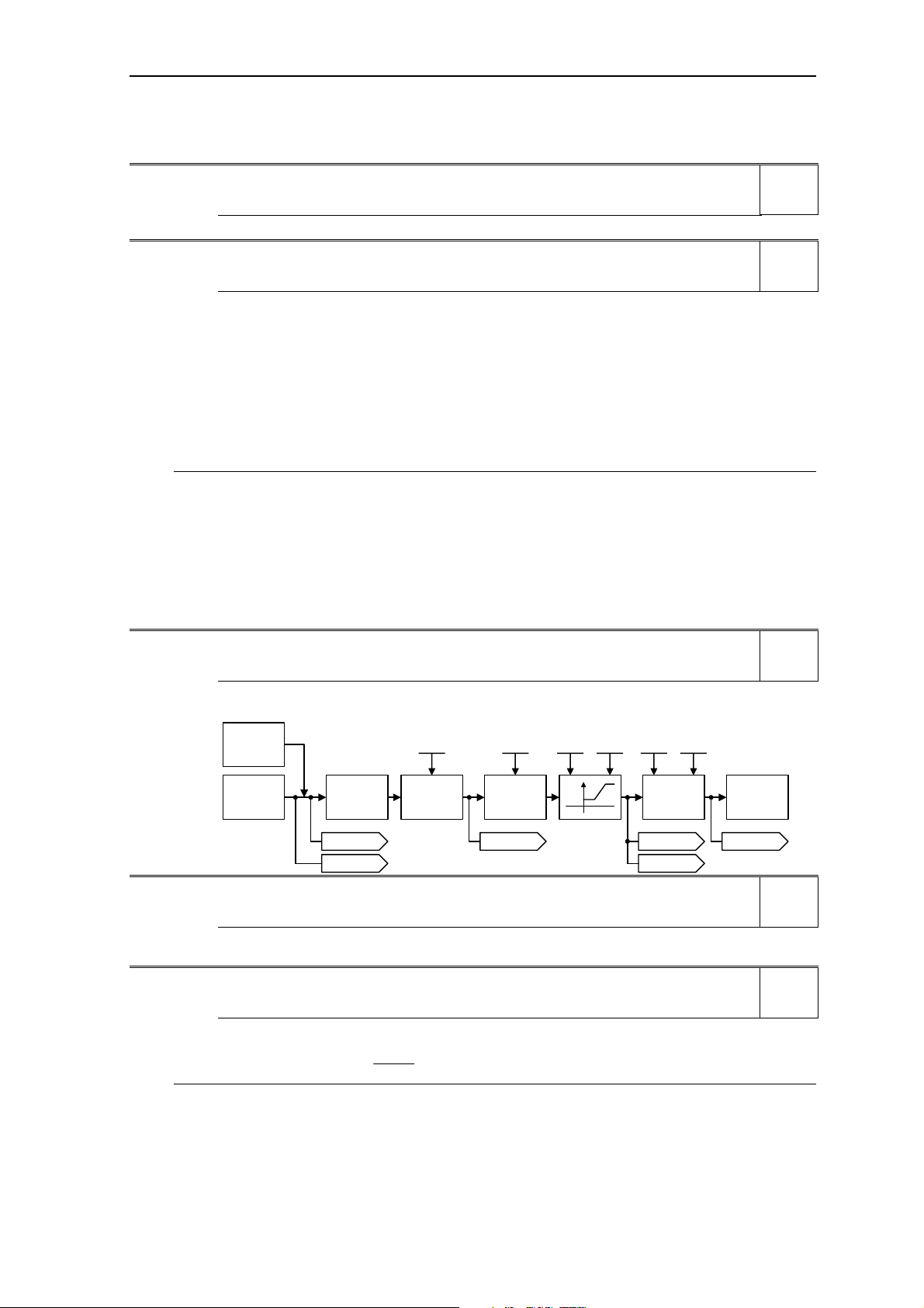
r0020 CO: Freq. setpoint before RFG Min: -
Datatype: Float Unit: Hz Def: -
P-Group: CONTROL Max: -
Displays actual frequency setpoint (input from ramp function generator).
Level
1
Level
3
Level
3
JOG
P1110 P1091 P1080 P1082 P 1120 P1135
. . .
Setpoint
source
Reverse
r1079 r0020 r1170
r1078
Inhibit
neg. freq.
setpoint
Skip
frequency
r1114
IfI
RFG
r1119
r0021 CO: Act. filtered frequency 1 Min: -
Datatype: Float Unit: Hz Def: -
P-Group: CONTROL Max: -
Displays actual inverter output frequency (r0021) excluding slip compensation, resonance damping and
frequency limitation.
r0022 Act. filtered rotor speed Min: -
Datatype: Float Unit: 1/min Def: -
P-Group: CONTROL Max: -
Displays calculated rotor speed based on inverter output frequency [Hz] x 120 / number of poles.
60
[Hz] r0021 [1/min] r0022 ⋅=
r0313
Note:
This calculation makes no allowance for load-dependent slip.
Motor
control
Level
2
Level
3
MICROMASTER 440 Parameter List
6SE6400-5BB00-0BP0
29
Page 30

Parameter Description Issue 01/06
r0024 CO: Act. filtered output freq. Min: -
Datatype: Float Unit: Hz Def: -
P-Group: CONTROL Max: -
Displays actual output frequency. Slip compensation, resonance damping and frequency limitation are
included.
r0025 CO: Act. filtered output voltage Min: -
Datatype: Float Unit: V Def: -
P-Group: CONTROL Max: -
Displays [rms] voltage applied to motor.
r0026 CO: Act. filtered DC-link volt. Min: -
Datatype: Float Unit: V Def: -
P-Group: INVERTER Max: -
Displays DC-link voltage.
Mains
200 - 240 V 380 - 480 V 500 - 600 V
U
DC_max_trip
U
DC_min_trip
U
DC_max_warn
U
DC_max_ctrl
U
DC_min_warn
U
DC_min_ctrl
U
DC_Comp
U
DC_Chopper
F0002
F0003 215 V
A0502
(P1240)
A0503
(P1240)
(P1236)
(P1237)
420 V (FS A - C)
410 V (FS D - F)
840 V (FS A - C)
820 V (FS D - F)
820 V (FS FX, GX)
430 V (FS A - F)
380 V (FS FX, GX)
r1242
[%] P1245
100
⋅⋅
r1242 0.98⋅
r1242 0.98⋅
1020 V
530 V
P02102
r0027 CO: Act. filtered output current Min: -
Datatype: Float Unit: A Def: -
P-Group: CONTROL Max: -
Displays [rms] value of motor current [A].
r0029 CO: Act. filtered current Isd Min: -
Datatype: Float Unit: A Def: -
P-Group: CONTROL Max: -
Displays flux-generating current component.
The flux-generating current component is based on the nominal flux, which is calculated from the motor
parameters (P0340 - Calculation of motor parameters).
Dependency:
Applies when vector control is selected in P1300 (control mode); otherwise, the display shows the value
zero.
Note:
The flux-generating current component is generally constant up to the base speed of the motor; above base
speed, this component is weakened (field weakening) thus enabling an increase in motor speed but at
reduced torque.
r0030 CO: Act. filtered current Isq Min: -
Datatype: Float Unit: A Def: -
P-Group: CONTROL Max: -
Displays torque-generating current component.
Note:
For asynchronous motors, a limit is calculated for the torque generating current component (in conjunction
with the maximum possible output voltage (r0071), motor leakage and current field weakening (r0377)) and
this prevents motor stalling.
Level
3
Level
2
Level
2
Level
2
Level
3
Level
3
MICROMASTER 440 Parameter List
30 6SE6400-5BB00-0BP0
Page 31

Issue 01/06 Parameter Description
r0031 CO: Act. filtered torque Min: -
Datatype: Float Unit: Nm Def: -
P-Group: CONTROL Max: -
Displays electrical torque.
3
L
m
m
M
2
L
R
Valid for V /f-caracteristic:
cos |i| u
s
≈
i
sq
R
e
⋅Ψ⋅⋅⋅=
iZ
sqrdp
2
|i|
⋅−ϕ⋅⋅
s
s
:
m
Motor torque
M
:
Z
Pole pair number
p
:
Ψ
Rotor flux
rd
:
L
Rotor inductance
R
:
L
Magnetizing inductance
m
:
Torque-generating current
i
sq
Motor counter EMF
:e
Output value will be zero at low speeds when the current injection is active (r1751.5 = 1).
Note:
The electrical torque is not the same as the mechanical torque, which can be measured on the shaft. Due to
windage and friction a part of the electrical torque is lost in the motor.
r0032 CO: Act. filtered power Min: -
Datatype: Float Unit: - Def: -
P-Group: CONTROL Max: -
Displays motor power (power output at the motor shaft).
M f 2 M P
⋅⋅π⋅=⋅ω=
1
1000
r0022
π 2
60
[Nm] r0031 [1/min]
Motor
ω, M
mech
⇒
[kW ] r0032 ⋅⋅⋅⋅=
Level
2
Level
2
[kW] r0032 0.75 [hp] r0032 ⋅=
Dependency:
Value is displayed in [kW] or [hp] depending on setting for P0100 (operation for Europe / North America).
r0035[3] CO: Act. motor temperature Min: -
Datatype: Float Unit: °C Def: -
P-Group: MOTOR Max: -
Displays measured motor temperature.
Index:
r0035[0] : 1st. Drive data set (DDS)
r0035[1] : 2nd. Drive data set (DDS)
r0035[2] : 3rd. Drive data set (DDS)
Level
2
MICROMASTER 440 Parameter List
6SE6400-5BB00-0BP0
31
Page 32

Parameter Description Issue 01/06
r0036 CO:Inverter overload utilization Min: -
Datatype: Float Unit: % Def: -
P-Group: INVERTER Max: -
Displays inverter overload utilization calculated via I2t model.
The actual I2t value relative to the max. possible I2t value supplies utilization in [%].
If the current exceeds the threshold for P0294 (inverter I2t overload warning), alarm A0505 (inverter I2t) is
generated and the output current of the inverter reduced via P0290 (inverter overload reaction).
If 100 % utilization is exceeded, alarm F0005 (inverter I2t) is tripped.
Example:
Normalized output current
r0027
r0207
100 %
Reaction via P0290
Default: "current reduction"
i2t [%]
r0036
P0294 (95 %)
A0505
1
0
Dependency:
r0036 > 0:
If the nominal current of the inverter is exceed, utilization will be displayed. Otherwise, 0 % utilization is
displayed.
r0037[5] CO: Inverter temperature [°C] Min: -
Datatype: Float Unit: °C Def: -
P-Group: INVERTER Max: -
Displays measured heatsink temperature and calculated junction temperature of IGBTs based on thermal
model.
Index:
r0037[0] : Measured heat sink temperature
r0037[1] : Chip temperature
r0037[2] : Rectifier temperature
r0037[3] : Inverter ambient temperature
r0037[4] : Control board temperature
r0038 CO: Act. power factor Min: -
Datatype: Float Unit: - Def: -
P-Group: CONTROL Max: -
Displays actual power factor.
Dependency:
Applies when V/f control is selected in P1300 (control mode); otherwise, the display shows the value 1.
r0039 CO: Energy consumpt. meter [kWh] Min: -
Datatype: Float Unit: kWh Def: -
P-Group: INVERTER Max: -
Displays electrical energy used by inverter since display was last reset (see P0040 - reset energy
consumption meter).
tt
r0039
Dependency:
Value is reset when P0040 = 1 (reset energy consumption meter).
act
=
P
∫
act
=⋅
∫
W
00
dtcosiu3dt
⋅ϕ⋅⋅⋅
Level
4
t
t
t
Level
3
Level
3
Level
2
MICROMASTER 440 Parameter List
32 6SE6400-5BB00-0BP0
Page 33

Issue 01/06 Parameter Description
P0040 Reset energy consumption meter Min: 0
CStat: CT Datatype: U16 Unit: - Def: 0
P-Group: INVERTER Active: first confirm QuickComm.: No Max: 1
Resets value of parameter r0039 (energy consumption meter) to zero.
Possible Settings:
0 No reset
1 Reset r0039 to 0
Dependency:
No reset until "P" is pressed.
r0050 CO: Active command data set Min: -
Datatype: U16 Unit: - Def: -
P-Group: COMMANDS Max: -
Displays currently selected and active command data set (CDS).
Possible Settings:
0 1st. Command data set (CDS)
1 2nd. Command data set (CDS)
2 3rd. Command data set (CDS)
Details:
See parameter P0810.
r0051[2] CO: Active drive data set (DDS) Min: -
Datatype: U16 Unit: - Def: -
P-Group: COMMANDS Max: -
Displays currently selected and active drive data set (DDS).
Possible Settings:
0 1st. Drive data set (DDS)
1 2nd. Drive data set (DDS)
2 3rd. Drive data set (DDS)
Index:
r0051[0] : Selected drive data set
r0051[1] : Active drive data set
Details:
See parameter P0820.
Level
2
Level
2
Level
2
MICROMASTER 440 Parameter List
6SE6400-5BB00-0BP0
33
Page 34

Parameter Description Issue 01/06
r0052 CO/BO: Act. status word 1 Min: -
Datatype: U16 Unit: - Def: -
P-Group: COMMANDS Max: -
Displays first active status word of inverter (bit format) and can be used to diagnose inverter status.
Bitfields:
Bit00 Drive ready 0 NO 1 YES
Bit01 Drive ready to run 0 NO 1 YES
Bit02 Drive running 0 NO 1 YES
Bit03 Drive fault active 0 NO 1 YES
Bit04 OFF2 active 0 YES 1 NO
Bit05 OFF3 active 0 YES 1 NO
Bit06 ON inhibit active 0 NO 1 YES
Bit07 Drive warning active 0 NO 1 YES
Bit08 Deviation setpoint / act. value 0 YES 1 NO
Bit09 PZD control 0 NO 1 YES
Bit10 Maximum frequency reached 0 NO 1 YES
Bit11 Warning: Motor current limit 0 YES 1 NO
Bit12 Motor holding brake active 0 NO 1 YES
Bit13 Motor overload 0 YES 1 NO
Bit14 Motor runs right 0 NO 1 YES
Bit15 Inverter overload 0 YES 1 NO
Dependency:
r0052 Bit00 - Bit02:
State-sequence diagram after Power On or ON/OFF1 respectively: ==> see below
Power ON
Drive ready
r0052
Bit00
ON/OFF1
Pre-charging active
Drive ready to run
r0052
Bit01
Pulse enable
Drive running
r0052
Bit02
Ramping finished
r0053
Bit09
r0052 Bit03 "Drive fault active":
Output of Bit3 (Fault) will be inverted on digital output (Low = Fault, High = No Fault).
r0052 Bit08 "Deviation setpoint / act. value" ==> see parameter P2164
r0052 Bit10 "f_act >= P1082 (f_max)" ==> see parameter P1082
r0052 Bit12 "Motor holding brake active" ==> see parameter P1215
1
1
0
1
0
1
0
1
0
1
0
1
0
1
0
Level
2
t0
t
t
t
t
t
t
t
MICROMASTER 440 Parameter List
34 6SE6400-5BB00-0BP0
Page 35

Issue 01/06 Parameter Description
r0052 Bit14 "Motor runs right" ==> see below
ON/OFF1
ON
r0054
Bit00
Reverse
r0054
Bit11
f
act
0 t
Drive running
r0052
Bit02
Motor runs
right
r0052
Bit14
left
not defined
last state is displayed
Details:
The 7-segment display of the bit-parameters (binary parameters) is explained in the Introduction of the
Parameter List.
r0053 CO/BO: Act. status word 2 Min: -
Datatype: U16 Unit: - Def: -
P-Group: COMMANDS Max: -
Displays second status word of inverter (in bit format).
Bitfields:
Bit00 DC brake active 0 NO 1 YES
Bit01 f_act > P2167 (f_off) 0 NO 1 YES
Bit02 f_act <= P1080 (f_min) 0 NO 1 YES
Bit03 Act. current r0027 > P2170 0 NO 1 YES
Bit04 f_act > P2155 (f_1) 0 NO 1 YES
Bit05 f_act <= P2155 (f_1) 0 NO 1 YES
Bit06 f_act >= setpoint 0 NO 1 YES
Bit07 Act. Vdc r0026 < P2172 0 NO 1 YES
Bit08 Act. Vdc r0026 > P2172 0 NO 1 YES
Bit09 Ramping finished 0 NO 1 YES
Bit10 PID output r2294 == P2292 (PID_min) 0 NO 1 YES
Bit11 PID output r2294 == P2291 (PID_max) 0 NO 1 YES
Bit14 Download data set 0 from AOP 0 NO 1 YES
Bit15 Download data set 1 from AOP 0 NO 1 YES
Note:
- r0053 Bit00 ==> see parameter P1233
- r0053 Bit01 ==> see parameter P2167
- r0053 Bit02 ==> see parameter P1080
- r0053 Bit03 ==> see parameter P2170
- r0053 Bit04 ==> see parameter P2155
- r0053 Bit05 ==> see parameter P2155
- r0053 Bit06 ==> see parameter P2150
- r0053 Bit07 ==> see parameter P2172
- r0053 Bit08 ==> see parameter P2172
t
t
t
t
Level
2
MICROMASTER 440 Parameter List
6SE6400-5BB00-0BP0
35
Page 36

Parameter Description Issue 01/06
r0053 Bit09 "Ramping finished" ==> see below
ON
OFF
f
f
set
f
act
Ramping finished
1
r0053
Bit09
0
Details:
See description of seven-segment display given in the "Introduction to MICROMASTER System
Parameters" in this manual.
r0054 CO/BO: Act. control word 1 Min: -
Datatype: U16 Unit: - Def: -
P-Group: COMMANDS Max: -
Displays first control word of inverter and can be used to diagnose which commands are active.
Bitfields:
Bit00 ON/OFF1 0 NO 1 YES
Bit01 OFF2: Electrical stop 0 YES 1 NO
Bit02 OFF3: Fast stop 0 YES 1 NO
Bit03 Pulses enabled 0 NO 1 YES
Bit04 RFG enable 0 NO 1 YES
Bit05 RFG start 0 NO 1 YES
Bit06 Setpoint enable 0 NO 1 YES
Bit07 Fault acknowledge 0 NO 1 YES
Bit08 JOG right 0 NO 1 YES
Bit09 JOG left 0 NO 1 YES
Bit10 Control from PLC 0 NO 1 YES
Bit11 Reverse (setpoint inversion) 0 NO 1 YES
Bit13 Motor potentiometer MOP up 0 NO 1 YES
Bit14 Motor potentiometer MOP down 0 NO 1 YES
Bit15 CDS Bit 0 (Local/Remote) 0 NO 1 YES
Details:
See description of seven-segment display given in the "Introduction to MICROMASTER System
Parameters" in this manual.
r0055 CO/BO: Act. control word 2 Min: -
Datatype: U16 Unit: - Def: -
P-Group: COMMANDS Max: -
Displays additional control word of inverter and can be used to diagnose which commands are active.
Bitfields:
Bit00 Fixed frequency Bit 0 0 NO 1 YES
Bit01 Fixed frequency Bit 1 0 NO 1 YES
Bit02 Fixed frequency Bit 2 0 NO 1 YES
Bit03 Fixed frequency Bit 3 0 NO 1 YES
Bit04 Drive data set (DDS) Bit 0 0 NO 1 YES
Bit05 Drive data set (DDS) Bit 1 0 NO 1 YES
Bit08 PID enabled 0 NO 1 YES
Bit09 DC brake enabled 0 NO 1 YES
Bit11 Droop enabled 0 NO 1 YES
Bit12 Torque control 0 NO 1 YES
Bit13 External fault 1 0 YES 1 NO
Bit15 Command data set (CDS) Bit 1 0 NO 1 YES
Details:
See description of seven-segment display given in the "Introduction to MICROMASTER System
Parameters" in this handbook.
t
t
t
Level
3
Level
3
MICROMASTER 440 Parameter List
36 6SE6400-5BB00-0BP0
Page 37

Issue 01/06 Parameter Description
r0056 CO/BO: Status of motor control Min: -
Datatype: U16 Unit: - Def: -
P-Group: CONTROL Max: -
Displays status of motor control (MM420: V/f status), which can be used to diagnose inverter status.
Bitfields:
Bit00 Init. control finished 0 NO 1 YES
Bit01 Motor demagnetizing finished 0 NO 1 YES
Bit02 Pulses enabled 0 NO 1 YES
Bit03 Voltage soft start selected 0 NO 1 YES
Bit04 Motor excitation finished 0 NO 1 YES
Bit05 Starting boost active 0 NO 1 YES
Bit06 Acceleration boost active 0 NO 1 YES
Bit07 Frequency is negative 0 NO 1 YES
Bit08 Field weakening active 0 NO 1 YES
Bit09 Volts setpoint limited 0 NO 1 YES
Bit10 Slip frequency limited 0 NO 1 YES
Bit11 F_out > F_max Freq. limited 0 NO 1 YES
Bit12 Phase reversal selected 0 NO 1 YES
Bit13 I-max controller active 0 NO 1 YES
Bit14 Vdc-max controller active 0 NO 1 YES
Bit15 KIB (Vdc-min control) active 0 NO 1 YES
Details:
See description of seven-segment display given in the introduction.
r0061 CO: Act. encoder frequency Min: -
Datatype: Float Unit: Hz Def: -
P-Group: CONTROL Max: -
Displays actual frequency detected by encoder.
r0062 CO: Freq. setpoint Min: -
Datatype: Float Unit: Hz Def: -
P-Group: CONTROL Max: -
Displays frequency setpoint of vector controller.
r0063 CO: Act. frequency Min: -
Datatype: Float Unit: Hz Def: -
P-Group: CONTROL Max: -
Displays actual unfiltered frequency. This value is not smoothed in contrary to r0021.
60
Act. frequencies:
V/f
160 ms
P1300
r0313
Act. filtered speed
r0022
Act. filtered frequency
r0021
Level
3
Level
2
Level
3
Level
3
SLVC
(Observer
model)
r0313
⋅
Encoder
MICROMASTER 440 Parameter List
6SE6400-5BB00-0BP0
<20
20 ,22
P0400
P0408 60
0
0
1, 2
21 ,23
P1300 = 21,23 and P0400 = 0 --> F0090
Act. frequency
r0063
Act. encoder frequency
r0061
37
Page 38

Parameter Description Issue 01/06
r0064 CO: Dev. frequency controller Min: -
Datatype: Float Unit: Hz Def: -
P-Group: CONTROL Max: -
Displays actual deviation of speed controller.
This value is calculated from the frequency setpoint (r0062) and the actual frequency (r0063).
Dependency:
Applies when vector control is selected in P1300 (control mode); otherwise, the display shows the value
zero.
r0065 CO: Slip frequency Min: -
Datatype: Float Unit: % Def: -
P-Group: CONTROL Max: -
Displays slip frequency of motor in [%] relative to the rated motor frequency (P0310).
Details:
For V/f control, see also P1335 (slip compensation).
r0066 CO: Act. output frequency Min: -
Datatype: Float Unit: Hz Def: -
P-Group: CONTROL Max: -
Displays actual output frequency.
Note:
The output frequency is limited by the values entered in P1080 (min. frequency) and P1082 (max.
frequency).
r0067 CO: Act. output current limit Min: -
Datatype: Float Unit: A Def: -
P-Group: CONTROL Max: -
Displays valid maximum output current of inverter.
Parameter r0067 is influenced/determined by the following factors:
- Rated motor current P0305
- Motor overload factor P0640
- Motor protection in dependency of P0610
- r0067 is less than or equal to maximum inverter current r0209
- Inverter protection in dependency of P0290
P0305
Level
3
Level
3
Level
3
Level
3
P0640
Motor
Inverter
Note:
A reduction of r0067 may indicate an inverter overload or a motor overload.
Motor protection
r0209
Inverter protection
Min
r0067
r0068 CO: Output current Min: -
Datatype: Float Unit: A Def: -
P-Group: CONTROL Max: -
Displays unfiltered [rms] value of motor current [A].
Note:
This is used for the process control (contrary to the smoothed output current r0027, that is used for display).
r0069[6] CO: Act. phase currents Min: -
Datatype: Float Unit: A Def: -
P-Group: CONTROL Max: -
Displays phase currents.
Index:
r0069[0] : U_phase
r0069[1] : V_phase
r0069[2] : W_phase
r0069[3] : Offset U_phase
r0069[4] : Offset V_phase
r0069[5] : Offset W_phase
Level
3
Level
4
MICROMASTER 440 Parameter List
38 6SE6400-5BB00-0BP0
Page 39

Issue 01/06 Parameter Description
r0070 CO: Act. DC-link voltage Min: -
Datatype: Float Unit: V Def: -
P-Group: INVERTER Max: -
Displays (unfiltered) DC-link voltage.
Note:
Used for process control purposes (in contrast to r0026 (actual DC-link voltage), which is filtered and is
used to display the value on the BOP/AOP).
r0071 CO: Max. output voltage Min: -
Datatype: Float Unit: V Def: -
P-Group: CONTROL Max: -
Displays maximum output voltage.
V
r0071
V
max
(Inverter)
P0304
V
(Motor)
V
= f(Vdc,MOD
max
n
P0310
f
(Motor)
(Inverter)
n
max
)
V
out
f
Level
3
Level
3
P, Φ
Power
Flux
1
~
f
Field weakening
Dependency:
- The actual maximum output voltage depends on the actual incoming line supply voltage.
- The maximum possible output voltage r0071 of the drive inverter is determined by the DC link voltage
r0026 and the maximum modulation depth P1803 in the gating unit.
- The maximum output voltage r0071 is tracked with the DC link voltage so that the highest possible
value is always and automatically achieved.
- The output voltage only reaches the calculated maximum value under steady-state conditions at the
rated load.
- In the no-load and partial load ranges, lower output voltages r0025 are obtained.
f
r0072 CO: Act. output voltage Min: -
Datatype: Float Unit: V Def: -
P-Group: CONTROL Max: -
Displays output voltage.
r0074 CO: Act. modulation Min: -
Datatype: Float Unit: % Def: -
P-Group: CONTROL Max: -
Displays actual modulation index.
The modulation index is defined as ratio between the magnitude of the fundamental component in the
inverter phase output voltage and half of the dc-link voltage.
Level
3
Level
4
MICROMASTER 440 Parameter List
6SE6400-5BB00-0BP0
39
Page 40

Parameter Description Issue 01/06
r0075 CO: Current setpoint Isd Min: -
Datatype: Float Unit: A Def: -
P-Group: CONTROL Max: -
Displays setpoint of flux generating current component.
Dependency:
Applies when vector control is selected in P1300 (control mode); otherwise, the display shows the value
zero.
r0076 CO: Act. current Isd Min: -
Datatype: Float Unit: A Def: -
P-Group: CONTROL Max: -
Displays flux generating current component.
Dependency:
Applies when vector control is selected in P1300 (control mode); otherwise, the display shows the value
zero.
r0077 CO: Current setpoint Isq Min: -
Datatype: Float Unit: A Def: -
P-Group: CONTROL Max: -
Displays setpoint for component of torque generating current.
Dependency:
Applies when vector control is selected in P1300 (control mode); otherwise, the display shows the value
zero.
r0078 CO: Act. current Isq Min: -
Datatype: Float Unit: A Def: -
P-Group: CONTROL Max: -
Displays component of torque generating current.
r0079 CO: Torque setpoint (total) Min: -
Datatype: Float Unit: Nm Def: -
P-Group: CONTROL Max: -
Displays total torque setpoint.
Dependency:
Applies when vector control is selected in P1300 (control mode); otherwise, the display shows the value
zero.
r0080 CO: Act. torque Min: -
Datatype: Float Unit: Nm Def: -
P-Group: CONTROL Max: -
Displays actual torque. Output value will be zero at low frequencies when current injection is active (r1751.5
= 1).
r0084 CO: Act. air gap flux Min: -
Datatype: Float Unit: % Def: -
P-Group: CONTROL Max: -
Displays air gap flux in [%] relative to the rated motor flux.
r0086 CO: Act. active current Min: -
Datatype: Float Unit: A Def: -
P-Group: CONTROL Max: -
Displays active (real part) of motor current.
Dependency:
Applies when V/f control is selected in P1300 (control mode); otherwise, the display shows the value zero.
r0090 CO: Act. rotor angle Min: -
Datatype: Float Unit: ° Def: -
P-Group: CONTROL Max: -
Indicates the current angle of the rotor. This function is not available on single input channel encoders.
Level
3
Level
3
Level
3
Level
3
Level
3
Level
4
Level
4
Level
3
Level
2
MICROMASTER 440 Parameter List
40 6SE6400-5BB00-0BP0
Page 41

Issue 01/06 Parameter Description
P0095[10] CI: Display PZD signals Min: 0:0
CStat: CT Datatype: U32 Unit: - Def: 0:0
P-Group: CONTROL Active: first confirm QuickComm.: No Max: 4000:0
Selects source of display for PZD signals.
Index:
P0095[0] : 1st PZD signal
P0095[1] : 2nd PZD signal
P0095[2] : 3rd PZD signal
P0095[3] : 4th PZD signal
P0095[4] : 5th PZD signal
P0095[5] : 6th PZD signal
P0095[6] : 7th PZD signal
P0095[7] : 8th PZD signal
P0095[8] : 9th PZD signal
P0095[9] : 10th PZD signal
r0096[10] PZD signals Min: -
Datatype: Float Unit: % Def: -
P-Group: CONTROL Max: -
Displays PZD signals in [%].
Index:
r0096[0] : 1st PZD signal
r0096[1] : 2nd PZD signal
r0096[2] : 3rd PZD signal
r0096[3] : 4th PZD signal
r0096[4] : 5th PZD signal
r0096[5] : 6th PZD signal
r0096[6] : 7th PZD signal
r0096[7] : 8th PZD signal
r0096[8] : 9th PZD signal
r0096[9] : 10th PZD signal
Note:
r0096 = 100 % corresponds to 4000 hex.
Level
3
Level
3
MICROMASTER 440 Parameter List
6SE6400-5BB00-0BP0
41
Page 42

Parameter Description Issue 01/06
3.3 Inverter parameters (HW)
P0100 Europe / North America Min: 0
CStat: C Datatype: U16 Unit: - Def: 0
P-Group: QUICK Active: first confirm QuickComm.: Yes Max: 2
Determines whether power settings (e.g. nominal rating plate power - P0307) are expressed in [kW] or [hp].
The default settings for the nominal rating plate frequency (P0310) and maximum motor frequency (P1082)
are also set automatically here, in addition to reference frequency (P2000).
Possible Settings:
0 Europe [kW], frequency default 50 Hz
1 North America [hp], frequency default 60 Hz
2 North America [kW], frequency default 60 Hz
Dependency:
Where:
- Stop drive first (i.e. disable all pulses) before you change this parameter.
- P0100 can only be changed when P0010 = 1 (Commissioning mode) via the respective Commissioing
interface (e.g. BOP).
- Changing P0100 resets all rated motor parameters as well as other parameters that depend on the
rated motor parameters (see P0340 - calculation of motor parameters).
Changing P0100 overwrites the settings of the DIP50/60 switch (location shown in the diagram below):
1. Parameter P0100 has an higher priority than the DIP50/60 switch.
2. However, after the inverter is powered-on again and P0100 < 2, the DIP50/60 setting will take priority
and overwrite P0100.
3. The DIP50/60 switch does not have any effect, if P0100 = 2.
Power
cycle
commissioning
Level
1
Quick
P0010 = 1
P0100 = 2
Remove I/O board
DIP50/60
Frequency 50 Hz
Notice:
P0100 setting 2 (==> [kW], frequency default 60 [Hz]) is not overwritten by the setting of DIP switch 2 (see
diagram above).
?
no
DIP50/60 =
50 Hz
?
yes
Power in kW
P0100 = 0
yes
no
Power in kW
Frequency 60 Hz
P0100 = 2 P0100 = 1
yes
no
Power in hp
Frequency 60 Hz
P0199 Equipment system number Min: 0
CStat: UT Datatype: U16 Unit: - Def: 0
P-Group: - Active: first confirm QuickComm.: No Max: 255
Equipment system number This parameter has no operation effect.
P0100 = 2
?
no
P0100 = 1
?
yes
Level
2
MICROMASTER 440 Parameter List
42 6SE6400-5BB00-0BP0
Page 43

Issue 01/06 Parameter Description
z
z
z
z
z
z
z
z
z
r0200 Act. power stack code number Min: -
Datatype: U32 Unit: - Def: -
P-Group: INVERTER Max: -
Identifies hardware variant as shown in table below.
Code-
No.
41 6SE6440-2UC11-2AA x 1/3AC200-240V +10% -10% 47-63H
42 6SE6440-2UC12-5AA x 1/3AC200-240V +10% -10% 47-63H
43 6SE6440-2UC13-7AA x 1/3AC200-240V +10% -10% 47-63H
44 6SE6440-2UC15-5AA x 1/3AC200-240V +10% -10% 47-63H
45 6SE6440-2UC17-5AA x 1/3AC200-240V +10% -10% 47-63H
46 6SE6440-2AB11-2AAx 1AC200-240V +10% -10% 47-63Hz 0,12 0,12 Cl. A A
47 6SE6440-2AB12-5AAx 1AC200-240V +10% -10% 47-63Hz 0,25 0,25 Cl. A A
48 6SE6440-2AB13-7AAx 1AC200-240V +10% -10% 47-63Hz 0,37 0,37 Cl. A A
49 6SE6440-2AB15-5AAx 1AC200-240V +10% -10% 47-63Hz 0,55 0,55 Cl. A A
50 6SE6440-2AB17-5AAx 1AC200-240V +10% -10% 47-63Hz 0,75 0,75 Cl. A A
51 6SE6440-2UC21-1BAx 1/3AC200-240V +10% -10% 47-63H
52 6SE6440-2UC21-5BAx 1/3AC200-240V +10% -10% 47-63H
53 6SE6440-2UC22-2BAx 1/3AC200-240V +10% -10% 47-63H
54 6SE6440-2AB21-1BAx 1AC200-240V +10% -10% 47-63Hz 1,1 1,1 Cl. A B
55 6SE6440-2AB21-5BAx 1AC200-240V +10% -10% 47-63Hz 1,5 1,5 Cl. A B
56 6SE6440-2AB22-2BAx 1AC200-240V +10% -10% 47-63Hz 2,2 2,2 Cl. A B
57 6SE6440-2UC23-0CAx 1/3AC200-240V +10% -10% 47-63H
58 6SE6440-2UC24-0CAx 3AC200-240V +10% -10% 47-63Hz 4 5,5 no C
59 6SE6440-2UC25-5CAx 3AC200-240V +10% -10% 47-63Hz 5,5 7,5 no C
60 6SE6440-2AB23-0CAx 1AC200-240V +10% -10% 47-63Hz 3 3 Cl. A C
61 6SE6440-2AC23-0CA x 3AC200-240V +10% -10% 47-63Hz 3 3 Cl. A C
62 6SE6440-2AC24-0CA x 3AC200-240V +10% -10% 47-63Hz 4 5,5 Cl. A C
63 6SE6440-2AC25-5CA x 3AC200-240V +10% -10% 47-63Hz 5,5 7,5 Cl. A C
64 6SE6440-2UC27-5DAx 3AC200-240V +10% -10% 47-63Hz 7,5 11 no D
65 6SE6440-2UC31-1DAx 3AC200-240V +10% -10% 47-63Hz 11 15 no D
66 6SE6440-2UC31-5DAx 3AC200-240V +10% -10% 47-63Hz 15 18,5 no D
67 6SE6440-2AC27-5DA x 3AC200-240V +10% -10% 47-63Hz 7,5 11 Cl. A D
68 6SE6440-2AC31-1DA x 3AC200-240V +10% -10% 47-63Hz 11 15 Cl. A D
69 6SE6440-2AC31-5DA x 3AC200-240V +10% -10% 47-63Hz 15 18,5 Cl. A D
70 6SE6440-2UC31-8EA x 3AC200-240V +10% -10% 47-63Hz 18,5 22 no E
71 6SE6440-2UC32-2EA x 3AC200-240V +10% -10% 47-63Hz 22 30 no E
72 6SE6440-2AC31-8EAx 3A C200-240V +10% -10% 47-63Hz 18,5 22 Cl. A E
73 6SE6440-2AC32-2EAx 3A C200-240V +10% -10% 47-63Hz 22 30 Cl. A E
74 6SE6440-2UC33-0FAx 3AC200-240V +10% -10% 47-63Hz 30 37 no F
75 6SE6440-2UC33-7FAx 3AC200-240V +10% -10% 47-63Hz 37 45 no F
76 6SE6440-2UC34-5FAx 3AC200-240V +10% -10% 47-63Hz 45 45 no F
77 6SE6440-2AC33-0FAx 3AC200-240V +10% -10% 47-63Hz 30 37 Cl. A F
78 6SE6440-2AC33-7FAx 3AC200-240V +10% -10% 47-63Hz 37 45 Cl. A F
79 6SE6440-2AC34-5FAx 3AC200-240V +10% -10% 47-63Hz 45 45 Cl. A F
80 6SE6440-2UD13-7AA x 3AC380-480V +10% -10% 47-63Hz 0,37 0,37 no A
81 6SE6440-2UD15-5AA x 3AC380-480V +10% -10% 47-63Hz 0,55 0,55 no A
82 6SE6440-2UD17-5AA x 3AC380-480V +10% -10% 47-63Hz 0,75 0,75 no A
83 6SE6440-2UD21-1AA x 3AC380-480V +10% -10% 47-63Hz 1,1 1,1 no A
84 6SE6440-2UD21-5AA x 3AC380-480V +10% -10% 47-63Hz 1,5 1,5 no A
85 6SE6440-2UD22-2BAx 3AC380-480V +10% -10% 47-63Hz 2,2 2,2 no B
86 6SE6440-2UD23-0BAx 3AC380-480V +10% -10% 47-63Hz 3 3 no B
87 6SE6440-2UD24-0BAx 3AC380-480V +10% -10% 47-63Hz 4 4 no B
88 6SE6440-2AD22-2BAx 3AC380-480V +10% -10% 47-63Hz 2,2 2,2 Cl. A B
89 6SE6440-2AD23-0BAx 3AC380-480V +10% -10% 47-63Hz 3 3 Cl. A B
90 6SE6440-2AD24-0BAx 3AC380-480V +10% -10% 47-63Hz 4 4 Cl. A B
91 6SE6440-2UD25-5CAx 3AC380-480V +10% -10% 47-63Hz 5,5 7,5 no C
92 6SE6440-2UD27-5CAx 3AC380-480V +10% -10% 47-63Hz 7,5 11 no C
93 6SE6440-2UD31-1CAx 3AC380-480V +10% -10% 47-63Hz 11 15 no C
MM440
MLFB
Input Voltage & Frequency
CT PowerkWVT PowerkWInternal
0,12 0,12 no A
0,25 0,25 no A
0,37 0,37 no A
0,55 0,55 no A
0,75 0,75 no A
1,1 1,1 no B
1,5 1,5 no B
2,2 2,2 no B
33noC
Filter
Level
3
Frame
Size
MICROMASTER 440 Parameter List
6SE6400-5BB00-0BP0
43
Page 44

Parameter Description Issue 01/06
Code-
No.
94 6SE6440-2AD25-5CAx 3AC380-480V +10% -10% 47-63Hz 5,5 7,5 Cl. A C
95 6SE6440-2AD27-5CAx 3AC380-480V +10% -10% 47-63Hz 7,5 11 Cl. A C
96 6SE6440-2AD31-1CAx 3AC380-480V +10% -10% 47-63Hz 11 15 Cl. A C
97 6SE6440-2UD31-5DAx 3AC380-480V +10% -10% 47-63Hz 15 18,5 no D
98 6SE6440-2UD31-8DAx 3AC380-480V +10% -10% 47-63Hz 18,5 22 no D
99 6SE6440-2UD32-2DAx 3AC380-480V +10% -10% 47-63Hz 22 30 no D
100 6SE6440-2AD31-5DAx 3AC380-480V +10% -10% 47-63Hz 15 18,5 Cl. A D
101 6SE6440-2AD31-8DAx 3AC380-480V +10% -10% 47-63Hz 18,5 22 Cl. A D
102 6SE6440-2AD32-2DAx 3AC380-480V +10% -10% 47-63Hz 22 30 Cl. A D
103 6SE6440-2UD33-0EA x 3AC380-480V +10% -10% 47-63Hz 30 37 no E
104 6SE6440-2UD33-7EA x 3AC380-480V +10% -10% 47-63Hz 37 45 no E
105 6SE6440-2AD33-0EAx 3A C380-480V +10% -10% 47-63Hz 30 37 Cl. A E
106 6SE6440-2AD33-7EAx 3A C380-480V +10% -10% 47-63Hz 37 45 Cl. A E
107 6SE6440-2UD34-5FAx 3AC380-480V +10% -10% 47-63Hz 45 55 no F
108 6SE6440-2UD35-5FAx 3AC380-480V +10% -10% 47-63Hz 55 75 no F
109 6SE6440-2UD37-5FAx 3AC380-480V +10% -10% 47-63Hz 75 90 no F
110 6SE6440-2AD34-5FAx 3AC380-480V +10% -10% 47-63Hz 45 55 Cl. A F
111 6SE6440-2AD35-5FAx 3AC380-480V +10% -10% 47-63Hz 55 75 Cl. A F
112 6SE6440-2AD37-5FAx 3AC380-480V +10% -10% 47-63Hz 75 90 Cl. A F
113 6SE6440-2UE17-5CAx 3A C500-600V +10% -10% 47-63Hz 0,75 1,5 no C
114 6SE6440-2UE21-5CAx 3A C500-600V +10% -10% 47-63Hz 1,5 2,2 no C
115 6SE6440-2UE22-2CAx 3A C500-600V +10% -10% 47-63Hz 2,2 4 no C
116 6SE6440-2UE24-0CAx 3A C500-600V +10% -10% 47-63Hz 4 5,5 no C
117 6SE6440-2UE25-5CAx 3A C500-600V +10% -10% 47-63Hz 5,5 7,5 no C
118 6SE6440-2UE27-5CAx 3A C500-600V +10% -10% 47-63Hz 7,5 11 no C
119 6SE6440-2UE31-1CAx 3A C500-600V +10% -10% 47-63Hz 11 15 no C
120 6SE6440-2UE31-5DAx 3A C500-600V +10% -10% 47-63Hz 15 18,5 no D
121 6SE6440-2UE31-8DAx 3A C500-600V +10% -10% 47-63Hz 18,5 22 no D
122 6SE6440-2UE32-2DAx 3A C500-600V +10% -10% 47-63Hz 22 30 no D
123 6SE6440-2UE33-0EAx 3AC500-600V +10% -10% 47-63Hz 30 37 no E
124 6SE6440-2UE33-7EAx 3AC500-600V +10% -10% 47-63Hz 37 45 no E
125 6SE6440-2UE34-5FAx 3AC500-600V +10% -10% 47-63Hz 45 55 no F
126 6SE6440-2UE35-5FAx 3AC500-600V +10% -10% 47-63Hz 55 75 no F
127 6SE6440-2UE37-5FAx 3AC500-600V +10% -10% 47-63Hz 75 90 no F
1001 6SE6440-2UD38-8FAx 3AC400-480V +10% -10% 47-63Hz 90 110 no FX
1002 6SE6440-2UD41-1FAx 3AC400-480V +10% -10% 47-63Hz 110 132 no FX
1003 6SE6440-2UD41-3GAx 3AC400-480V +10% -10% 47-63Hz 132 160 no GX
1004 6SE6440-2UD41-6GAx 3AC400-480V +10% -10% 47-63Hz 160 200 no GX
1005 6SE6440-2UD42-0GAx 3AC400-480V +10% -10% 47-63Hz 200 250 no GX
Notice:
Parameter r0200 = 0 indicates that no power stack has been identified.
MM440
MLFB
Input Voltage & Frequency
CT PowerkWVT PowerkWInternal
P0201 Power stack code number Min: 0
CStat: C Datatype: U16 Unit: - Def: 0
P-Group: INVERTER Active: first confirm QuickComm.: No Max: 65535
Confirms actual power stack identified.
r0203 Act. inverter type Min: -
Datatype: U16 Unit: - Def: -
P-Group: INVERTER Max: -
Type number of actual inverter identified.
Possible Settings:
1 MICROMASTER 420
2 MICROMASTER 440
3 MICRO- / COMBIMASTER 411
4 MICROMASTER 410
5 Reserved
6 MICROMASTER 440 PX
7 MICROMASTER 430
Filter
Frame
Size
Level
3
Level
3
MICROMASTER 440 Parameter List
44 6SE6400-5BB00-0BP0
Page 45

Issue 01/06 Parameter Description
r0204 Power stack features Min: -
Datatype: U32 Unit: - Def: -
P-Group: INVERTER Max: -
Displays hardware features of power stack.
Bitfields:
Bit00 DC input voltage 0 NO 1 YES
Bit01 RFI filter 0 NO 1 YES
Note:
Parameter r0204 = 0 indicates that no power stack has been identified.
P0205 Inverter application Min: 0
CStat: C Datatype: U16 Unit: - Def: 0
P-Group: INVERTER Active: first confirm QuickComm.: Yes Max: 1
Selects inverter application.
The inverter and motor requirements are determined by the speed range and torque requirements of the
load. The relationship between speed and torque for different loads (constant torque loads or variable
torque loads).
Possible Settings:
0 Constant torque
1 Variable torque
Note:
Constant torque (CT):
CT is used if the application needs a constant torque on the whole frequency range. Many loads can be
considered to be constant torque loads. Typical constant torque loads are conveyors, compressors and
positve displacement pumps (see diagram).
Variable torque (VT):
VT is used if the application has a parabolic frequency-torque characteristic like many fans and pumps.
Variable torque allows with the same inverter:
- Higher rated inverter current r0207
- Higher rated inverter power r0206
- Higher threshold for I2t protection
If P0205 is modified in quick commissioning it immediately calculates various motor parameters:
- P0305 Rated motor current
- P0307 Rated motor power
- P0640 Motor overload factor
Torque
Power
Characteristic
1
~M
f
P = const. P ~ f P ~ f
P
M = const .
M
f~M
2
M ~ f
P ~ f
Level
3
Level
3
2
3
Application
Winders
Facing lathes
Rotary cutting
machines
MICROMASTER 440 Parameter List
6SE6400-5BB00-0BP0
M
f
P
f
Hoisting gear
Belt conveyors
Process machines
M
P
Calenders with
viscous friction
Eddy-current brakes
f
Pumps
Fans
Centrifuges
M
P
f
Involving forming
Rolling mills
Planers
Compressors
45
Page 46

Parameter Description Issue 01/06
It is recommended to modify P0205 first. Afterwards motor parameter may be adapted. Motor parameter will
be overridden by changing this sequence.
User
Inverter parameters
r0207 I
r0208 P
r0209 I
Motor parameters
P0305 I
P0307 P
P0640 I
Technology parameter
P0500
Notice:
- The parameter value is not reset by the factory setting (see P0970).
- To set P0205 = 1 (variable torque) is not possible for all inverters.
- Use setting 1 (variable torque) only for variable-torque applications (e.g. pumps and fans). If used for
constant-load applications, I2t warning will be produced too late, causing overheating in the motor.
r0206 Rated inverter power [kW] / [hp] Min: -
Datatype: Float Unit: - Def: -
P-Group: INVERTER Max: -
Displays nominal rated motor power from inverter.
Dependency:
Value is displayed in [kW] or [hp] depending on setting for P0100 (operation for Europe / North America).
r0207[3] Rated inverter current Min: -
Datatype: Float Unit: A Def: -
P-Group: INVERTER Max: -
Indicates the rated inverter current.
Index:
r0207[0] : Rated inverter current
r0207[1] : Rated VT current
r0207[2] : Rated CT current
Note:
VT (variable torque) and CT (constant torque) specify the overload capability (CT/VT application) of the
inverter. The definition of the rated as well as the overload and base load values depend on the inverter
type and inverter power. The different values can be taken from the appropriate Catalog or are saved in the
drive inverter (refer to Fig.).
The VT rated current r0207[1] or CT rated current r0207[2] represent the matching 4-pole Siemens IEC
standard motor for the selected load duty cycle (refer to the diagram). Parameters r0207[1] or r0207[2] are
used as default values for P0305 as a function of the CT/VT application (load duty cycle). If r0207[1] =
r0207[2], then it is not possible to make a differentiation between a CT/VT application.
Overload in operation is only possible if, before the overload condition, the load current was less than the
rated current. For drives, which must be able to handle overload conditions, it is first necessary to define a
base load current for the required load.
If the full overload capability is used, then this is detected using an I²t monitoring and the power module is
protected as a function of parameter P0290.
r0208 Rated inverter voltage Min: -
Datatype: U32 Unit: V Def: -
P-Group: INVERTER Max: -
Displays nominal AC supply voltage of inverter.
Value:
r0208 = 230 : 200 - 240 V +/- 10 %
r0208 = 400 : 380 - 480 V +/- 10 %
r0208 = 575 : 500 - 600 V +/- 10 %
I,n
I,n
I,max
P0500P0205
M,n
M,n
M,max
Control parameter
P1300
P1300
Level
2
[kW] r0206 0.75 [hp] r0206 ⋅=
Level
2
Level
2
MICROMASTER 440 Parameter List
46 6SE6400-5BB00-0BP0
Page 47

Issue 01/06 Parameter Description
r0209 Maximum inverter current Min: -
Datatype: Float Unit: A Def: -
P-Group: INVERTER Max: -
Displays maximum output current of inverter.
Dependency:
Parameter r0209 depends on the derating which is affected by pulse frequency P1800, ambient
temperature and altitude. The data of deration is given in the OPERATING INSRTRUCTION.
P0210 Supply voltage Min: 0
CStat: CT Datatype: U16 Unit: V Def: 230
P-Group: INVERTER Active: Immediately QuickComm.: No Max: 1000
Parameter P0210 defines the supply voltage.
Its default value depends upon the type of inverter. If P0210 does not correspond to the supply voltage, then
it must be modified.
When P0210 has been modified, the following thresholds are changed:
Dependency:
Optimizes Vdc controller, which extends the ramp-down time if regenerative energy from motor would
otherwise cause DC link overvoltage trips.
Reducing the value enables controller to cut in earlier and reduce the risk of overvoltage.
Set P1254 ("Auto detect Vdc switch-on levels") = 0. Cut-in levels for Vdc-controller and compound braking
are then derived directly from P0210 (supply voltage).
Vdc _min switch -on level
Vdc_max switch -on level
Compound braking switch-on level
Dynamic braking switch -on level
Note:
- If mains voltage is higher than value entered, automatic deactivation of the Vdc controller may occur to
avoid acceleration of the motor. An alarm will be issued in this case (A0910).
- Default value is depending on inverter type and its rating data.
0210P2 P1245 ⋅⋅=
0210P21.15 ⋅⋅=
0210P21.13 ⋅⋅=
0210P21.13 ⋅⋅=
r0231[2] Max. cable length Min: -
Datatype: U16 Unit: m Def: -
P-Group: INVERTER Max: -
Indexed parameter to display maximum allowable cable length between inverter and motor.
Index:
r0231[0] : Max. allowed unscreened cable length
r0231[1] : Max. allowed screened cable length
Notice:
For full EMC compliance, the screened cable must not exceed 25 m in length when an EMC filter is fitted.
Level
2
Level
3
Level
3
MICROMASTER 440 Parameter List
6SE6400-5BB00-0BP0
47
Page 48

Parameter Description Issue 01/06
P0290 Inverter overload reaction Min: 0
CStat: CT Datatype: U16 Unit: - Def: 2
P-Group: INVERTER Active: first confirm QuickComm.: No Max: 3
Selects reaction of inverter to an internal over-temperature.
Following physical values influence the inverter overload protection (see diagram):
- heat sink temperature
- junction temperature (IGBT temperature)
- inverter I²t
Inverter monitoring
2
t
r0036
r0037
Possible Settings:
0 Reduce output frequency
1 Trip (F0004)
2 Reduce pulse frequency and output frequency
3 Reduce pulse frequency then trip (F0004)
Notice:
P0290 = 0:
Reduction of output frequency is only effective if the load is also reduced. This is for example valid for
variable torque applications with a quadratic torque characteristic as pumps or fans.
A trip will always result, if the action taken does not sufficiently reduce internal temperature.
The pulse frequency P1800 is reduced only if higher than 2 kHz. The actual pulse frequency is displayed in
parameter r1801.
i
P0294
Heat sink
temperature
P0292
IGBT
temperature
P0292
Inverter overload reaction
P0290
i_max contr ol
(U/f)
Current control
(SLVC, VC)
f_pulse
control
P0291[3] Inverter protection Min: 0
CStat: CT Datatype: U16 Unit: - Def: 1
P-Group: INVERTER Active: Immediately QuickComm.: No Max: 7
Bit 02 shows if phase loss dedection (input phase) of 3 phase inverters is enabled after factory reset.
Default setting of phase loss is disabled for FSA - FSC. FSD and greater it is enabled.
Bitfields:
Bit00 Reserved 0 NO 1 YES
Bit01 Reserved 0 NO 1 YES
Bit02 Phase loss detection enable 0 NO 1 YES
Index:
P0291[0] : 1st. Drive data set (DDS)
P0291[1] : 2nd. Drive data set (DDS)
P0291[2] : 3rd. Drive data set (DDS)
Details:
See P0290 (inverter overload reaction)
Level
3
A0504
A0505
A0506
F0004
F0005
Level
4
MICROMASTER 440 Parameter List
48 6SE6400-5BB00-0BP0
Page 49

Issue 01/06 Parameter Description
P0292 Inverter temperature warning Min: 0
CStat: CUT Datatype: U16 Unit: °C Def: 5
P-Group: INVERTER Active: first confirm QuickComm.: No Max: 25
Defines the temperature difference (in ºC) between the Overtemperature trip threshold and the warning
threshold of the inverter. The trip threshold is stored internally by the inverter and cannot be changed by the
user.
Temperature warning threshold of inverter T_warn
T = T - P0292
warn
Temperature shutdown threshold of inverter T_trip
Temperature MM440, Frame Size
Heat sink
IGBT
Input rectifier -
Cooling air -
Control board -
If the actual inverter temperature (r0037) exceeds the corresponding threshold, a warning A0504, if the
temperature still increases then a fault F0004 will be displayed.
trip
A - C D - F
110 °C
140 °C
95 °C
145 °C
F
600 V
80 °C
145 °C
-
-
-
-
-
-
FX
95 kW
150 °C
110 kW
CT
88 °C
75 °C
55 °C
65 °C 65 °C
CT
91 °C
150 °C
75 °C
55 °C
GX
132 kW
145 °C
160 kW
CT
80 °C
75 °C
55 °C
65 °C 65 °C
82 °C
147 °C
75 °C
55 °C
CT
P0294 Inverter I2t overload warning Min: 10.0
CStat: CUT Datatype: Float Unit: % Def: 95.0
P-Group: INVERTER Active: first confirm QuickComm.: No Max: 100.0
Defines the [%] value at which alarm A0505 (inverter I2t) is generated.
Inverter I2t calculation is used to determine a maximum tolerable period for inverter overload. The I2t
calculation value is deemed = 100 % when this maximum tolerable period is reached.
Dependency:
That the output current of the inverter has been reduced and that the value of I2t does not exceed 100%.
Note:
P0294 = 100 % corresponds to stationary nominal load.
P0295 Inverter fan off delay time Min: 0
CStat: CUT Datatype: U16 Unit: s Def: 0
P-Group: TERMINAL Active: first confirm QuickComm.: No Max: 3600
Defines inverter fan switch off delay time in seconds after drive has stopped.
Note:
Setting to 0, inverter fan will switch off when the drive stops, that is no delay.
Level
200 kW
CT
88 °C
150 °C
75 °C
50 °C
65 °C
Level
Level
3
4
3
MICROMASTER 440 Parameter List
6SE6400-5BB00-0BP0
49
Page 50

Parameter Description Issue 01/06
3.4 Motor parameters
P0300[3] Select motor type Min: 1
CStat: C Datatype: U16 Unit: - Def: 1
P-Group: MOTOR Active: first confirm QuickComm.: Yes Max: 2
Selects motor type.
This parameter is required during commissioning to select motor type and optimize inverter performance.
Most motors are asynchronous; if in doubt, use the formula below.
60
P0310 x ⋅=
P0311
Synchronous motorx = 1, 2, ..., n :
x ≠ 1, 2, ..., n : Asynchronous motor
If the result is a whole number, the motor is synchronous.
Possible Settings:
1 Asynchronous rotational motor
2 Synchronous rotational motor
Index:
P0300[0] : 1st. Drive data set (DDS)
P0300[1] : 2nd. Drive data set (DDS)
P0300[2] : 3rd. Drive data set (DDS)
Dependency:
Changeable only when P0010 = 1 (quick commissioning).
If synchronous motor is selected, the following functions are not available:
- P0308 Power factor
- P0309 Motor efficiency
- P0346 Magnetization time
- P0347 Demagnetization time
- P1335 Slip compensation
- P1336 Slip limit
- P0320 Motor magnetizing current
- P0330 Rated motor slip
- P0331 Rated magnetization current
- P0332 Rated power factor
- P0384 Rotor time constant
- P1200, P1202, P1203 Flying start
- P1230, P1232, P1233 DC braking
Level
2
MICROMASTER 440 Parameter List
50 6SE6400-5BB00-0BP0
Page 51

Issue 01/06 Parameter Description
P0304[3] Rated motor voltage Min: 10
CStat: C Datatype: U16 Unit: V Def: 230
P-Group: MOTOR Active: first confirm QuickComm.: Yes Max: 2000
Nominal motor voltage [V] from rating plate. Following diagram shows a typical rating plate with the
locations of the relevant motor data.
Line supply voltage
MICROMASTER 410
MICROMASTER 411
MICROMASTER 420
MICROMASTER 430
MICROMASTER 440
1 AC 110 V *)
X
-
-
-
-
1 AC 230 V
X
-
X
-
X
3 AC 230 V
-
-
X
-
X
3 AC 400 V
X
X
X
X
Level
1
3 AC 500 V
-
-
-
-
X
*) Line supply voltage 1-ph. 110 V AC is stepped -up --> frequency inverter output voltage 3-ph. 230 V AC
Index:
P0304[0] : 1st. Drive data set (DDS)
P0304[1] : 2nd. Drive data set (DDS)
P0304[2] : 3rd. Drive data set (DDS)
Dependency:
- Changeable only when P0010 = 1 (quick commissioning).
- Default value is depending on inverter type and its rating data.
Caution:
The input of rating plate data must correspond with the wiring of the motor (star / delta). This means, if delta
wiring is used for the motor, delta rating plate data has to be entered.
IEC Motor
W2
W2U1U2V1V2
U1
V1
W1
Delta connection
W1
U1
V1
W1
U2V1V2
U1
Star connection
W1
e.g.: Volts 230 V (Delta connection) / 400 V (Star connection)
MICROMASTER 440 Parameter List
6SE6400-5BB00-0BP0
51
Page 52

Parameter Description Issue 01/06
T
NEMA Motor
1
Volts
low
high
UVW
T
1-T7T2-T8T3-T9
T1T2T
Connected
T4-T5-T
T
3
1-T7T2-T8T3-T9
together
6
e.g.: Volts 230 V YY (low) / 460 V Y (high)
Volts
low
high
UVW
T
1-T6-T7T2-T4-T8T3-T5-T9
T
T
1
T3T4-T7T5-T8T6-T
2
Connected
together
Connection
Y Y
Y
-
Connection
∆ ∆
9
T
T
3
∆
T
4
T
7
T
T
9
6
T
3
8
T
5
T
1
T
9
T
T
6
T5T
8
P0305[3] Rated motor current Min: 0.01
CStat: C Datatype: Float Unit: A Def: 3.25
P-Group: MOTOR Active: first confirm QuickComm.: Yes Max: 10000.00
Nominal motor current [A] from rating plate - see diagram in P0304.
Index:
P0305[0] : 1st. Drive data set (DDS)
P0305[1] : 2nd. Drive data set (DDS)
P0305[2] : 3rd. Drive data set (DDS)
Dependency:
- Changeable only when P0010 = 1 (quick commissioning).
- Default value is depending on inverter type and its rating data.
- Depends also on P0320 (motor magnetization current).
Note:
The maximum value of P0305 depends on the maximum inverter current r0209 and the motor type:
Asynchronous motor :
Synchronous motor :
It is recommanded that the ratio of P0305 (rated motor current) and r0207 (rated inverter current) should not
be lower than:
U/f :
≤
P0305 81
r0207
r0209 = P0305
asyn max,
r0209 2 = P0305
syn max,
⋅
T
2
T
4
7
T
2
Level
1
SLVC and VC :
≤
r0207
P0305 41
P0307[3] Rated motor power Min: 0.01
CStat: C Datatype: Float Unit: - Def: 0.12
P-Group: MOTOR Active: first confirm QuickComm.: Yes Max: 2000.00
Nominal motor power [kW/hp] from rating plate.
Index:
P0307[0] : 1st. Drive data set (DDS)
P0307[1] : 2nd. Drive data set (DDS)
P0307[2] : 3rd. Drive data set (DDS)
Dependency:
- If P0100 = 1, values will be in [hp] - see diagram P0304 (rating plate).
- Changeable only when P0010 = 1 (quick commissioning).
- Default value is depending on inverter type and its rating data.
Level
1
MICROMASTER 440 Parameter List
52 6SE6400-5BB00-0BP0
Page 53

Issue 01/06 Parameter Description
P0308[3] Rated motor cosPhi Min: 0.000
CStat: C Datatype: Float Unit: - Def: 0.000
P-Group: MOTOR Active: first confirm QuickComm.: Yes Max: 1.000
Nominal motor power factor (cosPhi) from rating plate - see diagram P0304.
Index:
P0308[0] : 1st. Drive data set (DDS)
P0308[1] : 2nd. Drive data set (DDS)
P0308[2] : 3rd. Drive data set (DDS)
Dependency:
- Changeable only when P0010 = 1 (quick commissioning).
- Visible only when P0100 = 0 or 2, (motor power entered in [kW]).
- Default value is depending on inverter type and its rating data.
- Setting 0 causes internal calculation of value. Calculated value see r0332.
P0309[3] Rated motor efficiency Min: 0.0
CStat: C Datatype: Float Unit: % Def: 0.0
P-Group: MOTOR Active: first confirm QuickComm.: Yes Max: 99.9
Nominal motor efficiency in [%] from rating plate.
Index:
P0309[0] : 1st. Drive data set (DDS)
P0309[1] : 2nd. Drive data set (DDS)
P0309[2] : 3rd. Drive data set (DDS)
Dependency:
- Changeable only when P0010 = 1 (quick commissioning).
- Visible only when P0100 = 1, (i.e. motor power entered in [hp]).
- Default value is depending on inverter type and its rating data.
- Setting 0 causes internal calculation of value. Calculated value see r0332.
Note:
P0309 = 100 % corresponds to superconducting.
Details:
See diagram in P0304 (rating plate).
P0310[3] Rated motor frequency Min: 12.00
CStat: C Datatype: Float Unit: Hz Def: 50.00
P-Group: MOTOR Active: first confirm QuickComm.: Yes Max: 650.00
Nominal motor frequency [Hz] from rating plate.
Index:
P0310[0] : 1st. Drive data set (DDS)
P0310[1] : 2nd. Drive data set (DDS)
P0310[2] : 3rd. Drive data set (DDS)
Dependency:
- Changeable only when P0010 = 1 (quick commissioning).
- Pole pair number recalculated automatically if parameter is changed.
Details:
See diagram in P0304 (rating plate)
P0311[3] Rated motor speed Min: 0
CStat: C Datatype: U16 Unit: 1/min Def: 0
P-Group: MOTOR Active: first confirm QuickComm.: Yes Max: 40000
Nominal motor speed [rpm] from rating plate.
Index:
P0311[0] : 1st. Drive data set (DDS)
P0311[1] : 2nd. Drive data set (DDS)
P0311[2] : 3rd. Drive data set (DDS)
Dependency:
- Changeable only when P0010 = 1 (quick commissioning).
- Setting 0 causes internal calculation of value.
- Slip compensation in V/f control requires rated motor speed for correct operation.
- Pole pair number recalculated automatically if parameter is changed.
- Default value is depending on inverter type and its rating data.
- Required for vector control and V/f control with speed controller.
Details:
See diagram in P0304 (rating plate)
Level
1
Level
1
Level
1
Level
1
MICROMASTER 440 Parameter List
6SE6400-5BB00-0BP0
53
Page 54

Parameter Description Issue 01/06
r0313[3] Motor pole pairs Min: -
Datatype: U16 Unit: - Def: -
P-Group: MOTOR Max: -
Displays number of motor pole pairs that the inverter is currently using for internal calculations.
Index:
r0313[0] : 1st. Drive data set (DDS)
r0313[1] : 2nd. Drive data set (DDS)
r0313[2] : 3rd. Drive data set (DDS)
Value:
r0313 = 1 : 2-pole motor
r0313 = 2 : 4-pole motor
etc.
Dependency:
Recalculated automatically when P0310 (rated motor frequency) or P0311 (rated motor speed) is changed.
P0310
60 r0313 ⋅=
P0311
P0314[3] Motor pole pair number Min: 0
CStat: C Datatype: U16 Unit: - Def: 0
P-Group: MOTOR Active: first confirm QuickComm.: Yes Max: 99
Specifies number of pole pairs of motor.
Index:
P0314[0] : 1st. Drive data set (DDS)
P0314[1] : 2nd. Drive data set (DDS)
P0314[2] : 3rd. Drive data set (DDS)
Value:
P0314 = 1 : 2-pole motor
P0314 = 2 : 4-pole motor
etc.
Dependency:
Recalculated automatically when P0310 (rated motor frequency) or P0311 (rated motor speed) is changed.
P0320[3] Motor magnetizing current Min: 0.0
CStat: CT Datatype: Float Unit: % Def: 0.0
P-Group: MOTOR Active: Immediately QuickComm.: Yes Max: 99.0
Defines motor magnetization current in [%] relative to P0305 (rated motor current).
Index:
P0320[0] : 1st. Drive data set (DDS)
P0320[1] : 2nd. Drive data set (DDS)
P0320[2] : 3rd. Drive data set (DDS)
Dependency:
Setting P0320 = 0: causes calculation by
- P0340 = 1 (data entered from rating plate) or by
- P3900 = 1 - 3 (end of quick commissioning). The calculated value is displayed in parameter r0331.
r0330[3] Rated motor slip Min: -
Datatype: Float Unit: % Def: -
P-Group: MOTOR Max: -
Displays nominal motor slip in [%] relative to P0310 (rated motor frequency) and P0311 (rated motor
speed).
P0311
[%] r0330 ⋅
=
Index:
r0330[0] : 1st. Drive data set (DDS)
r0330[1] : 2nd. Drive data set (DDS)
r0330[2] : 3rd. Drive data set (DDS)
P0310
P0310
60
r0313
⋅−
% 100
r0331[3] Rated magnetization current Min: -
Datatype: Float Unit: A Def: -
P-Group: MOTOR Max: -
Displays calculated magnetizing current of motor in [A].
Index:
r0331[0] : 1st. Drive data set (DDS)
r0331[1] : 2nd. Drive data set (DDS)
r0331[2] : 3rd. Drive data set (DDS)
Level
3
Level
3
Level
3
Level
3
Level
3
MICROMASTER 440 Parameter List
54 6SE6400-5BB00-0BP0
Page 55

Issue 01/06 Parameter Description
r0332[3] Rated power factor Min: -
Datatype: Float Unit: - Def: -
P-Group: MOTOR Max: -
Displays power factor for motor
Index:
r0332[0] : 1st. Drive data set (DDS)
r0332[1] : 2nd. Drive data set (DDS)
r0332[2] : 3rd. Drive data set (DDS)
Dependency:
Value is calculated internally if P0308 (rated motor cosPhi) set to 0; otherwise, value entered in P0308 is
displayed.
r0333[3] Rated motor torque Min: -
Datatype: Float Unit: Nm Def: -
P-Group: MOTOR Max: -
Displays rated motor torque.
Index:
r0333[0] : 1st. Drive data set (DDS)
r0333[1] : 2nd. Drive data set (DDS)
r0333[2] : 3rd. Drive data set (DDS)
Dependency:
Value is calculated from P0307 (rated motor power) and P0311 (rated motor speed).
⋅
=
[Nm] r0333
60
1000 [kW ] P0307
[1/min] P0311
π
⋅
2
P0335[3] Motor cooling Min: 0
CStat: CT Datatype: U16 Unit: - Def: 0
P-Group: MOTOR Active: first confirm QuickComm.: Yes Max: 3
Selects motor cooling system used.
Possible Settings:
0 Self-cooled: Using shaft mounted fan attached to motor
1 Force-cooled: Using separately powered cooling fan
2 Self-cooled and internal fan
3 Force-cooled and internal fan
Index:
P0335[0] : 1st. Drive data set (DDS)
P0335[1] : 2nd. Drive data set (DDS)
P0335[2] : 3rd. Drive data set (DDS)
Caution:
The following combination of parameter setting should not be combined:
- P0610 = 1 and P0335 = 0 or 2 :
When P0335 = 0 or 2 the inverter cools the motor using a shaft mounted fan. If this is used in
conjunction with P0610 the cooling of the motor will be inefficient.
In essence, if the i2t calculation reduces the output frequency, then the shaft mounted fan will also reduce
its cooling effect, the motor will then eventually overheat and trip.
- Exception:
Applications with variable torque the reduction of max. current leeds automatically to a reduction of the
Notice:
load / output current.
Motors of series 1LA1 and 1LA8 have an internal fan. This internal motor fan must not be confused with the
fan at the end of the motor shaft.
Level
3
Level
3
Level
2
MICROMASTER 440 Parameter List
6SE6400-5BB00-0BP0
55
Page 56

Parameter Description Issue 01/06
P0340[3] Calculation of motor parameters Min: 0
CStat: CT Datatype: U16 Unit: - Def: 0
P-Group: MOTOR Active: first confirm QuickComm.: No Max: 4
Calculates various motor parameters (see table below). This parameter is required during commissioning to
optimize inverter performance.
Possible Settings:
0 No calculation
1 Complete parameterization
2 Calculation of equivalent circuit data
3 Calculation of V/f and vector control data
4 Calculation of controller settings only
Index:
P0340[0] : 1st. Drive data set (DDS)
P0340[1] : 2nd. Drive data set (DDS)
P0340[2] : 3rd. Drive data set (DDS)
Note:
P0340 = 0:
No calculation
P0340 = 1:
The motor weight/moment of inertia (P0344, P0341) are determined starting from the rating plate
parameters (P0300 - P0335), the motor equivalent circuit diagram parameters (ESB, P0350 - P0369). The
V/f control/vector control parameters and reference quantities are then pre-assigned (includes all of the
calculations from P0340 = 2,3,4).
P0340 = 2:
The motor equivalent circuit diagram parameters (ESB, P0350 - P0369) are calculated starting from the
rating plate parameters (without any other pre-assignments made).
P0340 = 3:
The V/f control/vector control parameters are determined (includes all calculations from P0340 = 4) starting
from the motor equivalent circuit diagram parameters (ESB, P0350 - P0369) and motor weight/moment of
inertia, moment of inertia ratio (P0344, P0341, P0342).
P0340 = 4:
The vector control parameters are pre-assigned starting from the motor equivalent circuit diagram
parameters (ESB, P0350 - P0369) and motor weight/moment of inertia, moment of inertia ratio (P0344,
P0341, P0342).
Level
2
MICROMASTER 440 Parameter List
56 6SE6400-5BB00-0BP0
Page 57

Issue 01/06 Parameter Description
P0341[3] Motor inertia [kg*m^2]
P0342[3] Total/motor inertia ratio
P0344[3] Motor weight
P0346[3] Magnetization time
P0347[3] Demagnetization time
P0350[3] Stator resistance (line-to-line )
P0352[3] Cable resistance
P0354[3] Rotor resistance
P0356[3] Stator leakage inductance
P0358[3] Rotor leakage inductance
P0360[3] Main inductance
P0362[3] Magnetizing curve flux 1
P0363[3] Magnetizing curve flux 2
P0364[3] Magnetizing curve flux 3
P0365[3] Magnetizing curve flux 4
P0366[3] Magnetizing curve imag 1
P0367[3] Magnetizing curve imag 2
P0368[3] Magnetizing curve imag 3
P0369[3] Magnetizing curve imag 4
P0625[3] Ambient motor temperature
P1253[3] Vdc-controller output limitation
P1316[3] Boost end frequency
P1460[3] Gain speed controller
P1462[3] Integral time speed controller
P1470[3] Gain speed controller (SLVC)
P1472[3] Integral time n-ctrl . (SLVC)
P1520[3] CO: Upper torque limit
P1521[3] CO: Lower torque limit
P1530[3] Motoring power limitation
P1531[3] Regenerative power limitation
P1715[3] Gain current controller
P1717[3] Integral time current controller
P1764[3] Kp of n-adaption (SLVC)
P1767[3] Tn of n-adaption (SLVC)
P2000[3] Reference frequency
P2002[3] Reference current
P2003[3] Reference torque
P2174[3] Torque threshold M_thresh
P2185[3] Upper torque threshold 1
P2186[3] Lower torque threshold 1
P2187[3] Upper torque threshold 2
P2188[3] Lower torque threshold 2
P2189[3] Upper torque threshold 3
P2190[3] Lower torque threshold 3
P0340 = 1
x
x
x
x
x
x
x
x
x
x
x
x
x
x
x
x
x
x
x
x
x
x
x
x
x
x
x
x
x
x
x
x
x
x
x
x
x
x
x
x
x
x
x
x
P0340 = 2
x
x
x
x
x
x
x
x
x
x
x
x
x
x
x
P0340 = 3
x
x
x
x
x
x
x
x
x
x
x
x
P0340 = 4
x
x
x
x
x
x
x
x
MICROMASTER 440 Parameter List
6SE6400-5BB00-0BP0
57
Page 58

Parameter Description Issue 01/06
P0341[3] Motor inertia [kg*m^2] Min: 0.00010
CStat: CUT Datatype: Float Unit: - Def: 0.00180
P-Group: MOTOR Active: Immediately QuickComm.: No Max: 1000.00000
Sets no-load inertia of motor.
Together with P0342 (inertia ratio total/motor) and P1496 (scaling factor acceleration), this value produces
the acceleration torque (r1517), which can be added to any additional torque produced from a BICO source
(P1511), and incorporated in the torque control function.
Index:
P0341[0] : 1st. Drive data set (DDS)
P0341[1] : 2nd. Drive data set (DDS)
P0341[2] : 3rd. Drive data set (DDS)
Note:
The result of P0341 * P0342 is included in the speed controller calculation. P0341 * P0342 (inertia ratio
total/motor) = total motor inertia
P1496 (scaling factor acceleration) = 100 % activates acceleration pre-control for the speed controller and
calculates the torque from P0341 (motor inertia) and P0342 (inertia ratio total/motor).
P0342[3] Total/motor inertia ratio Min: 1.000
CStat: CUT Datatype: Float Unit: - Def: 1.000
P-Group: MOTOR Active: Immediately QuickComm.: No Max: 400.000
Specifies ratio between total inertia (load + motor) and motor inertia.
Index:
P0342[0] : 1st. Drive data set (DDS)
P0342[1] : 2nd. Drive data set (DDS)
P0342[2] : 3rd. Drive data set (DDS)
P0344[3] Motor weight Min: 1.0
CStat: CUT Datatype: Float Unit: kg Def: 9.4
P-Group: MOTOR Active: Immediately QuickComm.: No Max: 6500.0
Specifies motor weight [kg].
Index:
P0344[0] : 1st. Drive data set (DDS)
P0344[1] : 2nd. Drive data set (DDS)
P0344[2] : 3rd. Drive data set (DDS)
Note:
- This value is used in the motor thermal model.
- It is normally calculated automatically from P0340 (motor parameters) but can also be entered
manually.
- Default value is depending on inverter type and its rating data.
r0345[3] Motor start-up time Min: -
Datatype: Float Unit: s Def: -
P-Group: MOTOR Max: -
Displays motor start-up time. This time corresponds to the standardized motor inertia.
The start-up time is the time taken to reach rated motor speed from standstill at acceleration with rated
motor torque (r0333).
Index:
r0345[0] : 1st. Drive data set (DDS)
r0345[1] : 2nd. Drive data set (DDS)
r0345[2] : 3rd. Drive data set (DDS)
P0346[3] Magnetization time Min: 0.000
CStat: CUT Datatype: Float Unit: s Def: 1.000
P-Group: MOTOR Active: Immediately QuickComm.: No Max: 20.000
Sets magnetization time [s], i.e. waiting time between pulse enable and start of ramp-up. Motor
magnetization builds up during this time.
Magnetization time is normally calculated automatically from the motor data and corresponds to the rotor
time constant (r0384).
Index:
P0346[0] : 1st. Drive data set (DDS)
P0346[1] : 2nd. Drive data set (DDS)
P0346[2] : 3rd. Drive data set (DDS)
Note:
- If boost settings are higher than 100 %, magnetization time may be reduced.
- Default value is depending on inverter type and its rating data.
- An excessive reduction of this time can result in insufficient motor magnetization.
Level
3
Level
3
Level
3
Level
3
Level
3
MICROMASTER 440 Parameter List
58 6SE6400-5BB00-0BP0
Page 59

Issue 01/06 Parameter Description
P0347[3] Demagnetization time Min: 0.000
CStat: CUT Datatype: Float Unit: s Def: 1.000
P-Group: MOTOR Active: Immediately QuickComm.: No Max: 20.000
Defines the de-magnetization time for the connected induction motor.
The de-magnetization time is the time that must expire between powering-down the drive (OFF2 or a drive
inverter fault/error) and powering-up again. The drive inverter is prevented from being powered-up again
within this time interval. The flux in the induction motor is reduced to a low value during this demagnetization time.
ON
OFF1
OFF2
inactive
active
f
Index:
P0347[0] : 1st. Drive data set (DDS)
P0347[1] : 2nd. Drive data set (DDS)
P0347[2] : 3rd. Drive data set (DDS)
Note:
- The de-magnetization time is approximately 250% of the rotor time constant (r0384) in seconds.
- The pre-assignment (default value) depends on the drive inverter type and its rated/nominal values.
- It is not active after a normal ramp-down - i.e. after OFF1 or OFF3.
- If this time is excessively shortened, then the drive inverter will be tripped (shut down) due to an
overcurrent condition.
- If a synchronous motor is connected, the de-magnetization time should be set to 0.
OFF2
Motor coasts down
P0347
t
t
t
P0350[3] Stator resistance (line-to-line) Min: 0.00001
CStat: CUT Datatype: Float Unit: Ohm Def: 4.00000
P-Group: MOTOR Active: Immediately QuickComm.: No Max: 2000.00000
Stator resistance value in [Ohms] for connected motor (from line-to-line). The parameter value includes the
cable resistance.
)RR( 2 0350P
+⋅=
SCable
There are three ways to determine the value for this parameter:
1. Calculate using
- P0340 = 1 (data entered from rating plate) or
- P0010 = 1, P3900 = 1,2 or 3 (end of quick commissioning).
2. Measure using P1910 = 1 (motor data identification - value for stator resistance is overwritten).
3. Measure manually using an Ohmmeter.
Index:
P0350[0] : 1st. Drive data set (DDS)
P0350[1] : 2nd. Drive data set (DDS)
P0350[2] : 3rd. Drive data set (DDS)
Note:
- Since measured line-to-line, this value may appear to be higher (up to 2 times higher) than expected.
- The value entered in P0350 (stator resistance) is the one obtained by the method last used.
- Default value is depending on inverter type and its rating data.
Level
3
Level
2
MICROMASTER 440 Parameter List
6SE6400-5BB00-0BP0
59
Page 60

Parameter Description Issue 01/06
P0352[3] Cable resistance Min: 0.0
CStat: CUT Datatype: Float Unit: Ohm Def: 0.0
P-Group: MOTOR Active: Immediately QuickComm.: No Max: 120.0
Describes cable resistance between inverter and motor for one phase.
d
Inverter
M
l
l : Cable length d : Cable diameter
l
R ⋅ρ=
A
A : Cable cross-section
: Specific resistanceρ
Index:
P0352[0] : 1st. Drive data set (DDS)
P0352[1] : 2nd. Drive data set (DDS)
P0352[2] : 3rd. Drive data set (DDS)
ρ
Cu
2
d
⋅π=
A
2
=
2
mm
⋅Ω
0,0178
m
P0354[3] Rotor resistance Min: 0.0
CStat: CUT Datatype: Float Unit: Ohm Def: 10.0
P-Group: MOTOR Active: Immediately QuickComm.: No Max: 300.0
Sets rotor resistance of motor equivalent circuit (phase value).
Index:
P0354[0] : 1st. Drive data set (DDS)
P0354[1] : 2nd. Drive data set (DDS)
P0354[2] : 3rd. Drive data set (DDS)
Dependency:
Calculated automatically using the motor model or determined using P1910 (motor identification).
P0356[3] Stator leakage inductance Min: 0.00001
CStat: CUT Datatype: Float Unit: - Def: 10.00000
P-Group: MOTOR Active: Immediately QuickComm.: No Max: 1000.00000
Sets stator leakage inductance [mH] of motor equivalent circuit (phase value).
Stator leakage reactance:
0356P
⋅⋅π⋅=⋅⋅π⋅=⋅ω=
f2
LX
Index:
P0356[0] : 1st. Drive data set (DDS)
P0356[1] : 2nd. Drive data set (DDS)
P0356[2] : 3rd. Drive data set (DDS)
Dependency:
Calculated automatically using the motor model or determined using P1910 (motor identification).
L
SSS
σσσ
0310P2
1000
P0358[3] Rotor leakage inductance Min: 0.0
CStat: CUT Datatype: Float Unit: - Def: 10.0
P-Group: MOTOR Active: Immediately QuickComm.: No Max: 1000.0
Sets rotor leakage inductance [mH] of motor equivalent circuit (phase value).
Rotor leakage reactance:
f2
LX
Index:
P0358[0] : 1st. Drive data set (DDS)
P0358[1] : 2nd. Drive data set (DDS)
P0358[2] : 3rd. Drive data set (DDS)
Dependency:
Calculated automatically using the motor model or determined using P1910 (motor identification).
L
RRR
σσσ
0358P
⋅⋅π⋅=⋅⋅π⋅=⋅ω=
0310P2
1000
Level
3
Level
4
Level
4
Level
4
MICROMASTER 440 Parameter List
60 6SE6400-5BB00-0BP0
Page 61

Issue 01/06 Parameter Description
P0360[3] Main inductance Min: 0.0
CStat: CUT Datatype: Float Unit: - Def: 10.0
P-Group: MOTOR Active: Immediately QuickComm.: No Max: 3000.0
Sets main inductance [mH] of the motor equivalent circuit (phase value), see diagram below.
Main reactance:
f2
LX
L
mmm
Index:
P0360[0] : 1st. Drive data set (DDS)
P0360[1] : 2nd. Drive data set (DDS)
P0360[2] : 3rd. Drive data set (DDS)
Dependency:
Calculated automatically using the motor model or determined using P1910 (motor identification).
Caution:
The data of equivalent circuit relates to the star equivalent circuit. Any data of the delta equivalent circuit
available, therefore must be transformed to the star equivalent circuit before entering into the inverter.
Note:
T-equivalent circuit :
On-state voltage
0.0 ... 20.0 [V ]
P1825 ( 1. 4)
Gating dead time
0.00 ... 3.50 [ us]
P1828 (0.50)
0360P
⋅⋅π⋅=⋅⋅π⋅=⋅ω=
0310P2
1000
P0350 = 2 (R + RS)
Cable resistance
0.0 ... 120.0 [ Ohm]
P0352.D ( 0.0)
Stator res . (L2L)
0.00001 ... 2000.00000 [Ohm]
P0350.D ( 4.00000)
Cable
Stator leak.induct
0.00001 ... 1000.00000
P0356.D (10.00000)
MotorCableInverter
Rotor leak.induct.
0.0 ... 1000.0
P0358.D (10.0)
iSi
R
Level
4
Rotor resistance
0. 0 ... 3 00.0 [Ohm]
P0354.D (10.0)
Invers - Γ
equivalent circuit :
Γ-
Γ Γ
R
Cabl e
C
Cabl e
Cable res. [%]
r0372.D
R
Cabl e
C
Cabl e
R
S
Main inductance
Stator res. [%]
r0370.D
R
S
0.0 ... 3000.0
P0360.D (10. 0)
Tot .leak.r eact. [%]
L
σS
r0377.D
X
σ
X
iSi
mΓ
L
σR
i
µ
L
m
LS= L
σS
= LσR+ L
L
R
RΓ
iµΓ (r0331)
Main reacta nce [%]
R
+ L
m
m
Rotor res . [%]
r0374.D
R
RΓ
r0382.D
R
MICROMASTER 440 Parameter List
6SE6400-5BB00-0BP0
61
Page 62

Parameter Description Issue 01/06
Conversion: T-equivalent curcuit -->
L
RRσ
+=
1
k
σ
L
m
L
m
=
L
mσΓ
k
R
R
R
=
R
RσΓ
2
k
R
L
R
σ
+=
LL
S
σσ
k
R
σ
Conversion:
k
L
1(1
2
=
k RR
⋅
RΓR
σΓ
LkL
S σσσσ
1(
R ΓσσΓσσσσ
)
k
σΓσ
L
⋅=⋅=
5.0
kL)k
Γ-
Γ Γ
L
σ
Γ
L
L
σ
0.51
⋅+=⋅−+=
L
mm Γ
5.0
⋅⋅=⋅⋅−=
kL
Γ-
Γ Γ
equivalent circuitInvers - Γ
T-equivalent curcuitequivalent circuit -->Invers - Γ
Rated motor impedance:
ZN=
V
I
V
ph
ph
N
=
⋅
I 3
0304P
=
⋅
N
0305P3
% 100 <=>
P0362[3] Magnetizing curve flux 1 Min: 0.0
CStat: CUT Datatype: Float Unit: % Def: 60.0
P-Group: MOTOR Active: Immediately QuickComm.: No Max: 300.0
Specifies first flux value of saturation characteristic in [%] relative to rated motor voltage (P0304).
The parameter settings for the values of P0362 to P0365 respectively P0366 to P0369 are illustrated in the
diagram below.
Φ [%]
P0365
P0364
100 %
P0363
Level
4
P0362
0
P0366 P0367 100 % P0368 P0369
i
[%]
µ
µ
r0331
[A]i
µ
[%]i
=
Index:
P0362[0] : 1st. Drive data set (DDS)
P0362[1] : 2nd. Drive data set (DDS)
P0362[2] : 3rd. Drive data set (DDS)
Note:
- P0362 = 100 % corresponds to rated motor flux
- Rated flux = rated EMF
- The value belongs to the first magnetizing current value and must be smaller than or equal to
magnetizing curve flux 2 (P0363).
- If the magnetization values entered in P0362 to P0365 respectively P0366 to P0369 do not match the
conditions (see below), a linear characteristic is applied internally.
P0365 ≥ P0364 ≥ P0363 ≥ P0362
P0369 ≥ P0368 ≥ P0367 ≥ P0366
P0363[3] Magnetizing curve flux 2 Min: 0.0
CStat: CUT Datatype: Float Unit: % Def: 85.0
P-Group: MOTOR Active: Immediately QuickComm.: No Max: 300.0
Specifies second flux value of saturation characteristic in [%] relative to rated motor voltage (P0304).
Index:
P0363[0] : 1st. Drive data set (DDS)
P0363[1] : 2nd. Drive data set (DDS)
P0363[2] : 3rd. Drive data set (DDS)
Details:
See P0362 (magnetizing curve flux 1).
Level
4
MICROMASTER 440 Parameter List
62 6SE6400-5BB00-0BP0
Page 63

Issue 01/06 Parameter Description
P0364[3] Magnetizing curve flux 3 Min: 0.0
CStat: CUT Datatype: Float Unit: % Def: 115.0
P-Group: MOTOR Active: Immediately QuickComm.: No Max: 300.0
Specifies third flux value of saturation characteristic in [%] relative to rated motor voltage (P0304).
Index:
P0364[0] : 1st. Drive data set (DDS)
P0364[1] : 2nd. Drive data set (DDS)
P0364[2] : 3rd. Drive data set (DDS)
Details:
See P0362 (magnetizing curve flux 1).
P0365[3] Magnetizing curve flux 4 Min: 0.0
CStat: CUT Datatype: Float Unit: % Def: 125.0
P-Group: MOTOR Active: Immediately QuickComm.: No Max: 300.0
Specifies fourth flux value of saturation characteristic in [%] relative to rated motor voltage (P0304).
Index:
P0365[0] : 1st. Drive data set (DDS)
P0365[1] : 2nd. Drive data set (DDS)
P0365[2] : 3rd. Drive data set (DDS)
Details:
See P0362 (magnetizing curve flux 1).
P0366[3] Magnetizing curve imag 1 Min: 0.0
CStat: CUT Datatype: Float Unit: % Def: 50.0
P-Group: MOTOR Active: Immediately QuickComm.: No Max: 500.0
Specifies first magnetizing current value of the saturation characteristic in [%] relative to the rated
magnetizing current (P0331).
Index:
P0366[0] : 1st. Drive data set (DDS)
P0366[1] : 2nd. Drive data set (DDS)
P0366[2] : 3rd. Drive data set (DDS)
Dependency:
Affects P0320 (motor magnetizing current).
Details:
See P0362 (magnetizing curve flux 1).
P0367[3] Magnetizing curve imag 2 Min: 0.0
CStat: CUT Datatype: Float Unit: % Def: 75.0
P-Group: MOTOR Active: Immediately QuickComm.: No Max: 500.0
Specifies second magnetizing current value of saturation characteristic in [%] relative to rated magnetizing
current (P0331).
Index:
P0367[0] : 1st. Drive data set (DDS)
P0367[1] : 2nd. Drive data set (DDS)
P0367[2] : 3rd. Drive data set (DDS)
Dependency:
Affects P0320 (motor magnetizing current).
Details:
See P0362 (magnetizing curve flux 1).
P0368[3] Magnetizing curve imag 3 Min: 0.0
CStat: CUT Datatype: Float Unit: % Def: 135.0
P-Group: MOTOR Active: Immediately QuickComm.: No Max: 500.0
Specifies third magnetizing current value of saturation characteristic in [%] relative to rated magnetizing
current (P0331).
Index:
P0368[0] : 1st. Drive data set (DDS)
P0368[1] : 2nd. Drive data set (DDS)
P0368[2] : 3rd. Drive data set (DDS)
Dependency:
Affects P0320 (motor magnetizing current).
Details:
See P0362 (magnetizing curve flux 1).
Level
4
Level
4
Level
4
Level
4
Level
4
MICROMASTER 440 Parameter List
6SE6400-5BB00-0BP0
63
Page 64

Parameter Description Issue 01/06
P0369[3] Magnetizing curve imag 4 Min: 0.0
CStat: CUT Datatype: Float Unit: % Def: 170.0
P-Group: MOTOR Active: Immediately QuickComm.: No Max: 500.0
Specifies fourth magnetizing current value of saturation characteristic in [%] relative to rated magnetizing
current (P0331).
Index:
P0369[0] : 1st. Drive data set (DDS)
P0369[1] : 2nd. Drive data set (DDS)
P0369[2] : 3rd. Drive data set (DDS)
Dependency:
Affects P0320 (motor magnetizing current).
Details:
See P0362 (magnetizing curve flux 1).
r0370[3] Stator resistance [%] Min: -
Datatype: Float Unit: % Def: -
P-Group: MOTOR Max: -
Displays standardized stator resistance of motor equivalent circuit (phase value) in [%] of the temperature
value in P0625.
Index:
r0370[0] : 1st. Drive data set (DDS)
r0370[1] : 2nd. Drive data set (DDS)
r0370[2] : 3rd. Drive data set (DDS)
Note:
Rated motor impedance:
ZN=
V
I
V
ph
ph
N
=
⋅
I 3
0304P
=
⋅
N
0305P3
% 100 <=>
r0372[3] Cable resistance [%] Min: -
Datatype: Float Unit: % Def: -
P-Group: MOTOR Max: -
Displays standardized cable resistance of motor equivalent circuit (phase value)in [%]. It is estimated to be
20 % of the stator resistance.
Index:
r0372[0] : 1st. Drive data set (DDS)
r0372[1] : 2nd. Drive data set (DDS)
r0372[2] : 3rd. Drive data set (DDS)
Note:
Rated motor impedance:
ZN=
V
I
V
ph
ph
N
=
⋅
I 3
0304P
=
⋅
N
0305P3
% 100 <=>
r0373[3] Rated stator resistance [%] Min: -
Datatype: Float Unit: % Def: -
P-Group: MOTOR Max: -
Displays the nominal stator resistance of the motor equivalent circuit diagram (phase value) as a [%] at the
ambient temperature + temperature rise of the stator winding.
Index:
r0373[0] : 1st. Drive data set (DDS)
r0373[1] : 2nd. Drive data set (DDS)
r0373[2] : 3rd. Drive data set (DDS)
Note:
- ambient temperature, refer to P0625
- temperature rise of the stator winding, refer to P0627
Rated motor impedance:
ZN=
V
I
V
ph
ph
N
=
⋅
I 3
0304P
=
⋅
N
0305P3
% 100 <=>
Level
4
Level
4
Level
4
Level
4
MICROMASTER 440 Parameter List
64 6SE6400-5BB00-0BP0
Page 65

Issue 01/06 Parameter Description
r0374[3] Rotor resistance [%] Min: -
Datatype: Float Unit: % Def: -
P-Group: MOTOR Max: -
Displays the rotor resistance of the motor equivalent circuit diagram (phase value) as a [%] at the ambient
temperature (in the cold state).
2
P0360 P0354
⋅
% 100
+
Z
N
% 100
⋅
2
P0358) (1
Index:
R
R
0374r
Γ
Z
N
R
R
% 100
=⋅=
2
⋅
Z
k
N
R
σ
=⋅
r0374[0] : 1st. Drive data set (DDS)
r0374[1] : 2nd. Drive data set (DDS)
r0374[2] : 3rd. Drive data set (DDS)
Note:
Ambient temperature, refer to P0625
Rated motor impedance:
ZN=
V
I
V
ph
ph
N
=
⋅
I 3
0304P
=
⋅
N
0305P3
% 100 <=>
r0376[3] Rated rotor resistance [%] Min: -
Datatype: Float Unit: % Def: -
P-Group: MOTOR Max: -
Displays the nominal rotor resistance of the motor equivalent circuit diagram (phase value) as a [%] at the
ambient temperature + temperature rise of the rotor winding.
Index:
r0376[0] : 1st. Drive data set (DDS)
r0376[1] : 2nd. Drive data set (DDS)
r0376[2] : 3rd. Drive data set (DDS)
Note:
- ambient temperature, refer to P0625
- temperature rise of the rotor winding, refer to P0628
Rated motor impedance:
ZN=
V
I
V
ph
ph
N
=
⋅
I 3
0304P
=
⋅
N
0305P3
% 100 <=>
r0377[3] Total leakage reactance [%] Min: -
Datatype: Float Unit: % Def: -
P-Group: MOTOR Max: -
Displays standardized total leakage reactance of the motor equivalent circuit (phase value) in [%].
Index:
L
R
σ
+
L
S
L
0377r
σ
Z
N
σ
k
R
% 100
=⋅=
σ
Z
=⋅
P0356
+
% 100
P0360 P0358
⋅
P0360 P0358
+
Z
NN
% 100
⋅
r0377[0] : 1st. Drive data set (DDS)
r0377[1] : 2nd. Drive data set (DDS)
r0377[2] : 3rd. Drive data set (DDS)
Note:
Rated motor impedance:
ZN=
V
I
V
ph
ph
N
=
⋅
I 3
0304P
=
⋅
N
0305P3
% 100 <=>
r0382[3] Main reactance [%] Min: -
Datatype: Float Unit: % Def: -
P-Group: MOTOR Max: -
Displays standardized main reactance of the motor equivalent circuit (phase value) in [%].
2
L
m
0382r
Γ
Z
N
Index:
r0382[0] : 1st. Drive data set (DDS)
r0382[1] : 2nd. Drive data set (DDS)
r0382[2] : 3rd. Drive data set (DDS)
Note:
Rated motor impedance:
ZN=
V
I
V
ph
ph
N
=
I 3
⋅
MICROMASTER 440 Parameter List
6SE6400-5BB00-0BP0
L
m
% 100
=⋅=
⋅
Z
k
N R
σ
0304P
=
⋅
N
=⋅
0305P3
P0360
% 100
Z
N
+
% 100
⋅
P0358) (P0360
% 100 <=>
Level
4
Level
4
Level
4
Level
4
65
Page 66

Parameter Description Issue 01/06
r0384[3] Rotor time constant Min: -
Datatype: Float Unit: ms Def: -
P-Group: MOTOR Max: -
Displays calculated rotor time constant [ms].
Index:
r0384[0] : 1st. Drive data set (DDS)
r0384[1] : 2nd. Drive data set (DDS)
r0384[2] : 3rd. Drive data set (DDS)
r0386[3] Total leakage time constant Min: -
Datatype: Float Unit: ms Def: -
P-Group: MOTOR Max: -
Displays total leakage time constant of motor.
Index:
r0386[0] : 1st. Drive data set (DDS)
r0386[1] : 2nd. Drive data set (DDS)
r0386[2] : 3rd. Drive data set (DDS)
r0394 CO: Stator resistance IGBT [%] Min: -
Datatype: Float Unit: % Def: -
P-Group: MOTOR Max: -
Displays stator resistance calculated in [%] from IGBT ON voltage and current amplitude.
Note:
Rated motor impedance:
ZN=
V
I
V
ph
ph
N
=
I 3
⋅
0304P
=
N
0305P3
⋅
% 100 <=>
r0395 CO: Total stator resistance [%] Min: -
Datatype: Float Unit: % Def: -
P-Group: MOTOR Max: -
Displays the actual stator resistance (combined stator/cable resistance) of the motor as a [%] as a function
of the actual stator winding temperature.
Note:
Actual stator winding temperature, refer to r0632
Rated motor impedance:
ZN=
V
I
V
ph
ph
N
=
I 3
⋅
0304P
=
N
0305P3
⋅
% 100 <=>
r0396 CO: Act. rotor resistance Min: -
Datatype: Float Unit: % Def: -
P-Group: MOTOR Max: -
Displays the actual rotor resistance of the motor equivalent circuit diagram (phase value) as a [%] as a
function of the actual rotor winding temperature.
Note:
- Actual rotor winding temperature, refer to r0633
- Values greater than 25 % tend to produce excessive motor slip. Check rated motor speed [rpm] value
(P0311).
Rated motor impedance:
ZN=
V
I
V
ph
ph
N
=
I 3
⋅
0304P
=
N
0305P3
⋅
% 100 <=>
Level
3
Level
4
Level
4
Level
3
Level
3
MICROMASTER 440 Parameter List
66 6SE6400-5BB00-0BP0
Page 67

Issue 01/06 Parameter Description
3.5 Speed encoder
P0400[3] Select encoder type Min: 0
CStat: CT Datatype: U16 Unit: - Def: 0
P-Group: ENCODER Active: Immediately QuickComm.: No Max: 2
Selects encoder type (number of encoder channels).
Possible Settings:
0 Disabled
1 Single channel encoder
2 Quadrature encoder without zero pulse
Index:
P0400[0] : 1st. Drive data set (DDS)
P0400[1] : 2nd. Drive data set (DDS)
P0400[2] : 3rd. Drive data set (DDS)
Dependency:
Following table displays the setting of P0400 which depends upon the number of encoder channels:
Parameter
P0400 = 1 A
P0400 = 2 single ended
Following table displays the setting the of the encoder DIPs on the encoder option modul which have to be
set depending on the encoder type (TTL, HTL) and encoder output:
Type
TTL
1XP8001-2)
HTL
1XP8001-1)
Caution:
When using Vector Control with encoder-feedback , the direction of rotation of the Encoder and Motor must
be the same. If this is not achieved, then the functional operation of the Vector Control will not be
guaranteed (positive instead of negative feedback). Extreme care must therefore be taken with respect to
the connection of the motor to the inverter as well as the correct connection of the encoder to the Encoder
module. Motor and Encoder must not be incorrectly wired up !
When commissioning Vector Control with encoder-feedback (VC), the drive should be configured for V/f
mode (see P1300) first. Run the drive and compare r0061 with r0021 that should agree in
- sign and
- magnitude (with a deviation of only a few percent).
Only if both criteria are fullfilled, change P1300 and select VC (P1300 = 21 or 23).
P0400 = 1 (single channel encoder) will only allow operation in one direction. If operation in both directions
is required, connect an encoder with 2 channels (A and B) and select setting 2. See the Operating
Instructions of the encoder module for more information.
Note:
Encoders with zero pulse can also be connected, but the zero pulse is not used in MM4.
The term "quadrature" in setting 2 refers to two periodic functions separated by a quarter cycle or 90
degrees.
Terminal Track Encoder output
A
AN
A
B
A
AN
B
BN
Output
differential
(e.g.
(e.g.
single ended
111111 010101
101010 000000
single ended
differential
differential
Level
2
MICROMASTER 440 Parameter List
6SE6400-5BB00-0BP0
67
Page 68

Parameter Description Issue 01/06
r0403 CO/BO: Encoder status word Min: -
Datatype: U16 Unit: - Def: -
P-Group: COMMANDS Max: -
Displays status word of encoder (in bit format).
Bitfields:
Bit00 Encoder module active 0 NO 1 YES
Bit01 Encoder error 0 NO 1 YES
Bit02 Signal o.k. 0 NO 1 YES
Bit03 Encoder low speed loss 0 NO 1 YES
Bit04 HW timer used 0 NO 1 YES
Details:
See description of seven-segment display given in the "Introduction to MICROMASTER System
Parameters" in this manual.
P0408[3] Encoder pulses per revolution Min: 2
CStat: CT Datatype: U16 Unit: - Def: 1024
P-Group: ENCODER Active: Immediately QuickComm.: No Max: 20000
Specifies the number of encoder pulses per revolution.
Index:
P0408[0] : 1st. Drive data set (DDS)
P0408[1] : 2nd. Drive data set (DDS)
P0408[2] : 3rd. Drive data set (DDS)
Note:
The encoder resolution (pulses per revolution P0408) which may be entered will be limited by the max.
pulse frequency of the encoder option board (f_max = 300 kHz).
The following equation calculates the encoder frequency depending on the encoder resoulution and the
rotational speed (rpm). The encoder frequency has to be less than the max. pulse frequency:
p0408 x rpm
> f =
f
max
60
P0491[3] Reaction on freq. signal loss Min: 0
CStat: CT Datatype: U16 Unit: - Def: 0
P-Group: ENCODER Active: first confirm QuickComm.: No Max: 1
Selects reaction on loss of frequency signal.
Possible Settings:
0 Do not change to SLVC
1 Change to SLVC
Index:
P0491[0] : 1st. Drive data set (DDS)
P0491[1] : 2nd. Drive data set (DDS)
P0491[2] : 3rd. Drive data set (DDS)
P0492[3] Allowed frequency difference Min: 0.00
CStat: CT Datatype: Float Unit: Hz Def: 10.00
P-Group: ENCODER Active: Immediately QuickComm.: No Max: 100.00
Parameter P0492 is used for low and high frequency encoder loss detection (fault: F0090).
1. High frequency encoder loss detection:
This condition occurs when the allowed frequency and the allowed difference of the frequency signals
between samples, set in P0492 is exceeded.
Condition:
- Act. freq. > P0492 and f(t_2) - f(t_1) > P0492
2. Low frequency encoder loss detection:
This condition occurs when the actual frequency is < P0492 when encoder loss occurs.
Condition a):
- r0061 = 0 and torque limit and then
- r0061 = 0 with setpoint frequency > 0 for time > P0494
or
Condition b):
Dependency:
Caution:
- Act. freq. < P0492 and f (t_2) < P0492 and ASIC detect channel B loss
This parameter is updated when motor start-up time P0345 is changed or when a frequency-loop
optimisation is performed (P1960 = 1). There is a fixed delay of 40 ms before acting upon loss of encoder at
high frequencies.
P0492 = 0 (disabled):
When allowed frequency difference is set to 0, both the high frequency and low frequency encoder loss
detection is disabled, thus encoder loss will not be detected.
If encoder loss detection is disabled and encoder loss occurs, then operation of the motor may become
unstable.
Level
2
Level
2
Level
2
Level
2
MICROMASTER 440 Parameter List
68 6SE6400-5BB00-0BP0
Page 69

Issue 01/06 Parameter Description
Note:
The value of P0492 should be approx. 2x rated slip, if the motor power is less (<=) 90 kW
The value of P0492 should be approx. 4x rated slip, if the motor power is greater (>) 90 kW
P0494[3] Delay frequency loss reaction Min: 0
CStat: CUT Datatype: U16 Unit: ms Def: 10
P-Group: ENCODER Active: first confirm QuickComm.: No Max: 65000
Used for low frequency encoder loss detection. If the motor shaft frequency is less than the value in P0492
then encoder loss is detected using a low frequency encoder loss detection algorithm. This parameter
selects the delay between loss of encoder at low frequency and reaction to the encoder loss.
Index:
P0494[0] : 1st. Drive data set (DDS)
P0494[1] : 2nd. Drive data set (DDS)
P0494[2] : 3rd. Drive data set (DDS)
Dependency:
This parameter is updated when motor start-up time P0345 is changed or when a frequency-loop
optimisation is performed (P1960 = 1).
Caution:
P0494 = 0 (disabled):
When the delay in P0494 is set to 0, then low frequency encoder loss detection is disabled and low
frequency encoder loss cannot be detected (high frequency encoder loss detection will still operate if P0492
> 0).
If low frequency encoder loss detection is disabled and encoder should be lost at low frequency, then
operation of motor may become unstable.
Level
2
3.6 Application macros
P0500[3] Technological application Min: 0
CStat: CT Datatype: U16 Unit: - Def: 0
P-Group: TECH_APL Active: first confirm QuickComm.: Yes Max: 3
Selects technological application. Sets control mode (P1300).
Possible Settings:
0 Constant torque
1 Pumps and fans
3 Simple Positioning
Index:
P0500[0] : 1st. Drive data set (DDS)
P0500[1] : 2nd. Drive data set (DDS)
P0500[2] : 3rd. Drive data set (DDS)
Dependency:
See parameter P0205
3.7 Motor temperature
P0601[3] Motor temperature sensor Min: 0
CStat: CUT Datatype: U16 Unit: - Def: 0
P-Group: MOTOR Active: first confirm QuickComm.: No Max: 2
Selects motor temperature sensor.
Possible Settings:
0 No sensor
1 PTC thermistor
2 KTY84
Index:
P0601[0] : 1st. Drive data set (DDS)
P0601[1] : 2nd. Drive data set (DDS)
P0601[2] : 3rd. Drive data set (DDS)
Dependency:
If "no sensor" is selected, the motor temperature monitoring will be done based on the estimated value of
the thermal motor model.
The temperature of the motor, when a thermal sensor is connected is calculated using the thermal motor
model. When a KTY sensor is fitted, the loss of connection can be detected (Alarm F0015). Using the
methods described above the monitoring of the temperature will automatically switch to the thermal model
using values derived from the estimated value. Using a PTC sensor the temperature of the motor is
calculated by the sensor in conjunction with the thermal model. This allows for redundancy of the monitoring
process.
Level
3
Level
2
MICROMASTER 440 Parameter List
6SE6400-5BB00-0BP0
69
Page 70

Parameter Description Issue 01/06
Fault
F0015
5 V
= 4 s
T
1
Signal
ADC
loss
detection
PTC
KTY
Equivalent
circuit data
Power dissipation
P
V,mot
Thermal motor model:
The data, required for the thermal motor model, is estimated from the rating plate data entered during the
quick commissioning. This data permits reliable, stable operation for standard Siemens motors. If required,
parameter changes must be made for motors from third-party manufacturers. We always recommend that
an automatic motor data identification run is made after quick commissioning so that the electrical
equivalent circuit diagram data can be determined. This allows a more precise calculation of the losses
which occur in the motor which has a positive impact on the accuracy of the thermal motor model.
PTC sensor:
A PTC temperature sensor (Positive-Temperature-Characteristic) is a resistor with a positive temperature
characteristic which, at normal temperatures, has a low resistance value ( 50-100 Ohm). Normally, three
PTC temperature sensors are connected in series in the motor (depending on the motor manufacturer), thus
producing a "cold resistance value" ranging from 150 to 300 Ohm. PTC temperature sensors are also
frequently referred to as cold conductors.
However, at a certain threshold temperature, the resistance rises rapidly. The threshold temperature is
selected by the motor manufacturer in such a way that it corresponds to the nominal temperature value of
the motor insulation. This allows the change in the resistance value to be deployed to protect the motor, as
the PTCs are embedded in the motor windings. PTC temperature sensors are not suitable for measuring
temperature.
When the PTC is connected to the control terminals 14 and 15 of the MM4 and the selection motor
temperature sensor has been activated by the setting P0601 = 1 (PTC sensor), the PTC temperature sensor
then protects the motor by means of the trip device in the MM4.
Should the resistance value of 2000 Ohm be exceeded, the inverter displays error F0011 (motor
overheating).
If the resistance value is below 100 Ohm, the error F0015 (no motor temperature signal) is then output.
This protects the motor from overheating and also from a sensor wire breakage.
The motor is additionally monitored by the thermal motor model in the inverter, thus providing a redundant
system for monitoring the motor.
KTY84 sensor:
The sensor KTY84 is basically a semi-conductor thermo-sensor (diode), the resistance value of which
varies from some 500 Ohm at 0°C to 2600 Ohm at 300°C. It has a positive temperature coefficient and, in
contrast to the PTCs, has an almost linear temperature characteristic. The resistor behaviour is comparable
to that of a measuring resistor with a very high temperature coefficient.
Note the following when connecting the polarity. Connect the sensor so that the diode is polarized in the
operative direction. That means that the anode needs to be connected to terminal 14 = PTC A (+) and the
cathode to terminal 15 = PTC B (-).
If the temperature monitoring function is activated with the setting P0601 = 2, the temperature of the sensor
(thus that of the motor windings) is then written to parameter r0035.
The motor overheating warning threshold needs to be assigned with parameter P0604 (the works setting is
130°C). This warning threshold depends on the motors thermal class. Also refer to the table below in this
context.
0
1
2
P0601
P0601 = 2
No sensor
PTC
KTY
ϑ
Thermal
motor
model
&
1
0
1≥
r0052
Bit13
Motor
temp.
reaction
r0035
V
r0631
1
0
P0604
P0610
r0632
r0633
MICROMASTER 440 Parameter List
70 6SE6400-5BB00-0BP0
Page 71

Issue 01/06 Parameter Description
Extract of IEC 85
End temperatureInsulation class
Y
A
E
B
F
H 180 °C
The motor overheating disturbance threshold is automatically set by the inverter at 10% higher than the
temperature declared in parameter P0604.
If the sensor KTY84 is activated, the motor temperature is then additionally calculated via the thermal motor
model. Should the sensor KTY84 recognise a wire breakage, an alarm F0015 (loss of the motor
temperature signal) is then generated and the thermal motor model is automatically switched to.
Connection failure:
If the connection to the PTC or KTY84 sensor becomes open circuit or short circuit, a fault will be indicated,
and by default the drive will trip.
P0604[3] Threshold motor temperature Min: 0.0
CStat: CUT Datatype: Float Unit: °C Def: 130.0
P-Group: MOTOR Active: Immediately QuickComm.: No Max: 200.0
Enters warning threshold for motor temperature protection.
The trip temperature defined always 10 % higher than the warning level P0604. When act. motor
temperature exeeds trip temperature than inverter trip as defined in P0610.
P0604 1.1 1.1
ϑϑ
warntrip
Index:
P0604[0] : 1st. Drive data set (DDS)
P0604[1] : 2nd. Drive data set (DDS)
P0604[2] : 3rd. Drive data set (DDS)
Dependency:
This value should be at least 40°C greater than the motor ambient temperature P0625.
⋅=⋅=
P0604 ≥ P0625 + 40 °C
Note:
Default value depends on P0300 (select motor type).
P0610[3] Motor temperature reaction Min: 0
CStat: CT Datatype: U16 Unit: - Def: 2
P-Group: MOTOR Active: first confirm QuickComm.: No Max: 2
Defines reaction when motor temperature reaches warning threshold.
Possible Settings:
0 Warning, no reaction, no trip
1 Warning, Imax reduction, trip F0011
2 Warning, no reaction, trip F0011
Index:
P0610[0] : 1st. Drive data set (DDS)
P0610[1] : 2nd. Drive data set (DDS)
P0610[2] : 3rd. Drive data set (DDS)
Dependency:
P0604 1.1 1.1
ϑϑ
warntrip
Note:
P0610 = 1:
If the max. permissible current Imax is reduced, this results in a lower output frequency.
The motor temperature depends on many factors. These factors include the size of the motor, the ambient
temperature, the previous motor load and naturally the load current.
Because most motors are cooled by fans integrated in the motor and running at the motor speed, the speed
of the motor is also important. Clearly a motor running with a high current (maybe due to boost) and a low
speed, will overheat more quickly than one running at 50 or 60 Hz, full load. The MM4 take account of these
factors.
⋅=⋅=
90 °C
105 °C
120 °C
130 °C
155 °C
Level
2
ϑ
:
warn
Warning threshold (P0604)
:
ϑ
trip
Trip threshold (max. permissible temperature)
Level
3
ϑ
:
warn
Warning threshold (P0604)
:
ϑ
trip
Trip threshold (max. permissible temperature)
MICROMASTER 440 Parameter List
6SE6400-5BB00-0BP0
71
Page 72

Parameter Description Issue 01/06
P0625[3] Ambient motor temperature Min: -40.0
CStat: CUT Datatype: Float Unit: °C Def: 20.0
P-Group: MOTOR Active: Immediately QuickComm.: No Max: 80.0
Ambient temperature of motor. The parameter for the stator resistance P0350 and rotor resistance P0354
relate to the ambient temperature.
P
P0625
Index:
P0625[0] : 1st. Drive data set (DDS)
P0625[1] : 2nd. Drive data set (DDS)
P0625[2] : 3rd. Drive data set (DDS)
Note:
Following items should be considered when using P0625:
- The ambient temperature has to be entered prior to motor data identification.
- An accuracy of +/- 5°C is adequate.
- The motor data identification should be carried out on a cold motor (ambient temperature = stator
temperature = rotor temperature).
- The highest accuracy at temperature adaption of the stator resistance and rotor resistance can be
achieved by connecting a KTY84 sensor.
P
0
6
2
6
Thermal
6
2
0
motor
model
P
0
6
7
2
8
r0630
r0631
r0632
r0633
P
P
0
3
0
4
P
0
3
0
5
0
3
0
7
Equivalent
circuit
P1910
P
P
0
3
0
8
P
0
0
1
3
0
P0626[3] Overtemperature stator iron Min: 20.0
CStat: CUT Datatype: Float Unit: °C Def: 50.0
P-Group: MOTOR Active: Immediately QuickComm.: No Max: 200.0
Overtemperature of stator iron.
Index:
P0626[0] : 1st. Drive data set (DDS)
P0626[1] : 2nd. Drive data set (DDS)
P0626[2] : 3rd. Drive data set (DDS)
Note:
See parameter P0627
Level
3
3
1
1
Level
4
MICROMASTER 440 Parameter List
72 6SE6400-5BB00-0BP0
Page 73

Issue 01/06 Parameter Description
P0627[3] Overtemperature stator winding Min: 20.0
CStat: CUT Datatype: Float Unit: °C Def: 80.0
P-Group: MOTOR Active: Immediately QuickComm.: No Max: 200.0
Overtemperature of the stator winding.
Index:
P0627[0] : 1st. Drive data set (DDS)
P0627[1] : 2nd. Drive data set (DDS)
P0627[2] : 3rd. Drive data set (DDS)
Note:
Temperature rise:
The losses occurring in the motor are converted into heat (thermal energy). This is the reason that
permissible limit temperature rises are defined for windings and other mechanical parts and components of
the motors. The temperature rise of the motor is defined as the difference between the temperature of a
motor component (e.g. rotor winding) and the temperature of the cooling medium (e.g. ambient air
temperature) (EN 60034-1). The temperature rise determined by the motor manufacturer by making the
appropriate measurements is the difference between the temperature of the winding at the end of the
measurement and the temperature of the cooling medium.
−=
ϑϑϑ
K2ü
The permissible temperature rises of the windings is classified in insulating classes. The insulating class
valid for the particular motor is specified on the motor rating plate.
The following points should be carefully observed:
- The temperature rises of the stator/rotor winding are only applicable for sinusoidal operation (basic
fundamental).
- The temperature of stator/rotor winding rises when the motor is fed with a sinusoidal voltage as well as
also losses (modulation losses, losses due to harmonics) caused as a result of drive converter
operation.
- The value may only be modified if the motor is in the cold condition (ambient temperature). The motor
identification run should be carried-out after the value has been changed.
: Temperature rise
ϑ
ü
: Temperature at the end of the measurement
ϑ
2
: Cooling-medium temperature
ϑ
K
P0628[3] Overtemperature rotor winding Min: 20.0
CStat: CUT Datatype: Float Unit: °C Def: 100.0
P-Group: MOTOR Active: Immediately QuickComm.: No Max: 200.0
Overtemperature of the rotor winding.
Index:
P0628[0] : 1st. Drive data set (DDS)
P0628[1] : 2nd. Drive data set (DDS)
P0628[2] : 3rd. Drive data set (DDS)
Note:
See parameter P0627
r0630[3] CO: Ambient temperature Min: -
Datatype: Float Unit: °C Def: -
P-Group: MOTOR Max: -
Displays ambient temperature of motor mass model.
Index:
r0630[0] : 1st. Drive data set (DDS)
r0630[1] : 2nd. Drive data set (DDS)
r0630[2] : 3rd. Drive data set (DDS)
r0631[3] CO: Stator iron temperature Min: -
Datatype: Float Unit: °C Def: -
P-Group: MOTOR Max: -
Displays iron temperature of motor mass model.
Index:
r0631[0] : 1st. Drive data set (DDS)
r0631[1] : 2nd. Drive data set (DDS)
r0631[2] : 3rd. Drive data set (DDS)
r0632[3] CO: Stator winding temperature Min: -
Datatype: Float Unit: °C Def: -
P-Group: MOTOR Max: -
Displays stator winding temperature of motor mass model.
Index:
r0632[0] : 1st. Drive data set (DDS)
r0632[1] : 2nd. Drive data set (DDS)
r0632[2] : 3rd. Drive data set (DDS)
Level
4
Level
4
Level
4
Level
4
Level
4
MICROMASTER 440 Parameter List
6SE6400-5BB00-0BP0
73
Page 74

Parameter Description Issue 01/06
r0633[3] CO: Rotor winding temperature Min: -
Datatype: Float Unit: °C Def: -
P-Group: MOTOR Max: -
Displays rotor winding temperature of motor mass model.
Index:
r0633[0] : 1st. Drive data set (DDS)
r0633[1] : 2nd. Drive data set (DDS)
r0633[2] : 3rd. Drive data set (DDS)
P0640[3] Motor overload factor [%] Min: 10.0
CStat: CUT Datatype: Float Unit: % Def: 150.0
P-Group: MOTOR Active: Immediately QuickComm.: Yes Max: 400.0
Defines motor overload current limit in [%] relative to P0305 (rated motor current).
Index:
P0640[0] : 1st. Drive data set (DDS)
P0640[1] : 2nd. Drive data set (DDS)
P0640[2] : 3rd. Drive data set (DDS)
Dependency:
Limited to maximum inverter current or to 400 % of rated motor current (P0305), whichever is the lower.
⋅
P0305) 4 (r0209, min
max
=
P0640
Details:
See function diagram for current limitation.
P0305
100
⋅
Level
4
Level
2
MICROMASTER 440 Parameter List
74 6SE6400-5BB00-0BP0
Page 75

Issue 01/06 Parameter Description
3.8 Command source
P0700[3] Selection of command source Min: 0
CStat: CT Datatype: U16 Unit: - Def: 2
P-Group: COMMANDS Active: first confirm QuickComm.: Yes Max: 6
Selects digital command source.
Possible Settings:
0 Factory default setting
1 BOP (keypad)
2 Terminal
4 USS on BOP link
5 USS on COM link
6 CB on COM link
Index:
P0700[0] : 1st. Command data set (CDS)
P0700[1] : 2nd. Command data set (CDS)
P0700[2] : 3rd. Command data set (CDS)
Example:
Changing form P0700 = 1 to P0700 = 2 sets all digital inputs to default settings.
BOP
Terminals
USS
BOP link
USS
COM link
CB
COM link
Caution:
Be aware, by changing of parameter P0700 all BI parameters are reset to the default value or modified as
listed in the table below.
If the Inverter is being controlled via the AOP, select USS (with the corresponding interface) for the
Command Source. If the AOP is connected to the BOP-Link Interface, then set Parameter P0700 to the
value 4 (P0700 = 4).
Note:
Changing this parameter sets (to default) all settings on item selected (see table).
P0700 = 0 P0700 = 1 P0700 = 2 P0700 = 4 P0700 = 5 P0700 = 6
P0701 1 0 1 0 0 0
P0702 12 0 12 0 0 0
P0703 9 9 9 9 9 9
P0704151515151515
P0705151515151515
P0706151515151515
P0707 0 0 0 0 0 0
P0708 0 0 0 0 0 0
P0731 52.3 52.3 52.3 52.3 52.3 52.3
P0732 52.7 52.7 52.7 52.7 52.7 52.7
P0733 0.0 0.0 0.0 0.0 0.0 0.0
P0800 0.0 0.0 0.0 0.0 0.0 0.0
P0801 0.0 0.0 0.0 0.0 0.0 0.0
P0700 = 2
Sequence control
Setpoint
channel
Motor
control
Level
1
MICROMASTER 440 Parameter List
6SE6400-5BB00-0BP0
75
Page 76

Parameter Description Issue 01/06
P0840 722.0 19.0 722.0 2032.0 2036.0 2090.0
P0842 0.0 0.0 0.0 0.0 0.0 0.0
P0844 1.0 19.1 1.0 2032.1 2036.1 2090.1
P0845 19.1 19.1 19.1 19.1 19.1 19.1
P0848 1.0 1.0 1.0 2032.2 2036.2 2090.2
P0849 1.0 1.0 1.0 1.0 1.0 1.0
P0852 1.0 1.0 1.0 2032.3 2036.3 2090.3
P0700 = 0 P0700 = 1 P0700 = 2 P0700 = 4 P0700 = 5 P0700 = 6
P1020 0.0 0.0 0.0 0.0 0.0 0.0
P1021 0.0 0.0 0.0 0.0 0.0 0.0
P1022 0.0 0.0 0.0 0.0 0.0 0.0
P1023 722.3 722.3 722.3 722.3 722.3 722.3
P1026 722.4 722.4 722.4 722.4 722.4 722.4
P1028 722.5 722.5 722.5 722.5 722.5 722.5
P1035 19.13 19.13 19.13 2032.13 2036.13 2090.13
P1036 19.14 19.14 19.14 2032.14 2036.14 2090.14
P1055 0.0 19.8 0.0 2032.8 2036.8 2090.8
P1056 0.0 0.0 0.0 2032.9 2036.9 2090.9
P1074 0.0 0.0 0.0 0.0 0.0 0.0
P1110 0.0 0.0 0.0 0.0 0.0 0.0
P1113 722.1 19.11 722.1 2032.11 2036.11 2090.11
P1124 0.0 0.0 0.0 0.0 0.0 0.0
P1140 1.0 1.0 1.0 2032.4 2036.4 2090.4
P1141 1.0 1.0 1.0 2032.5 2036.5 2090.5
P1142 1.0 1.0 1.0 2032.6 2036.6 2090.6
P1230 0.0 0.0 0.0 0.0 0.0 0.0
P1477 0.0 0.0 0.0 0.0 0.0 0.0
P1501 0.0 0.0 0.0 0.0 0.0 0.0
P2103 722.2 722.2 722.2 722.2 722.2 722.2
P2104 0.0 0.0 0.0 2032.7 2036.7 2090.7
P2106 1.0 1.0 1.0 1.0 1.0 1.0
P2200 0.0 0.0 0.0 0.0 0.0 0.0
P2220 0.0 0.0 0.0 0.0 0.0 0.0
P2221 0.0 0.0 0.0 0.0 0.0 0.0
P2222 0.0 0.0 0.0 0.0 0.0 0.0
P2223 722.3 722.3 722.3 722.3 722.3 722.3
P2226 722.4 722.4 722.4 722.4 722.4 722.4
P2228 722.5 722.5 722.5 722.5 722.5 722.5
P2235 19.13 19.13 19.13 2032.13 2036.13 2090.13
P2236 19.14 19.14 19.14 2032.14 2036.14 2090.14
The following parameters are not overwritten when changing P0700:
P0810 P0811 P0820 P0821 P2810 P2812 P2814
P2816 P2818 P2820 P2822 P2824 P2826 P2828
P2830 P2832 P2834 P2837 P2840 P2843 P2846
P2849 P2854 P2859 P2864
MICROMASTER 440 Parameter List
76 6SE6400-5BB00-0BP0
Page 77

Issue 01/06 Parameter Description
3.9 Digital inputs
P0701[3] Function of digital input 1 Min: 0
CStat: CT Datatype: U16 Unit: - Def: 1
P-Group: COMMANDS Active: first confirm QuickComm.: No Max: 99
Selects function of digital input 1.
DIN channel (e.g. DIN1 - PNP (P0725 = 1))
Kl.9
P24 (PNP)
Kl.28
0 V (NPN)
Possible Settings:
0 Digital input disabled
1 ON/OFF1
2 ON reverse /OFF1
3 OFF2 - coast to standstill
4 OFF3 - quick ramp-down
9 Fault acknowledge
10 JOG right
11 JOG left
12 Reverse
13 MOP up (increase frequency)
14 MOP down (decrease frequency)
15 Fixed setpoint (Direct selection)
16 Fixed setpoint (Direct selection + ON)
17 Fixed setpoint (Binary coded selection + ON)
25 DC brake enable
29 External trip
33 Disable additional freq setpoint
99 Enable BICO parameterization
Index:
P0701[0] : 1st. Command data set (CDS)
P0701[1] : 2nd. Command data set (CDS)
P0701[2] : 3rd. Command data set (CDS)
Dependency:
Setting 99 (enable BICO parameterization) requires
- P0700 command source or
- P0010 = 1, P3900 = 1, 2 or 3 quick commissioning or
- P0010 = 30, P0970 = 1 factory reset in order to reset.
Notice:
Setting 99 (BICO) for expert use only.
PNP/NPN DIN
24
V
0
1
0 V
0 ... 1
P0725 (1)
0
1
24 V
Debounce time : DIN
0 ... 3
P0724 (3)
T0
&
r0722
r0722
.0
CO/BO: Bin.inp.val
P0 70 1
Pxxxx BI : ...
Level
2
Function
MICROMASTER 440 Parameter List
6SE6400-5BB00-0BP0
77
Page 78

Parameter Description Issue 01/06
P0702[3] Function of digital input 2 Min: 0
CStat: CT Datatype: U16 Unit: - Def: 12
P-Group: COMMANDS Active: first confirm QuickComm.: No Max: 99
Selects function of digital input 2.
Possible Settings:
0 Digital input disabled
1 ON/OFF1
2 ON reverse /OFF1
3 OFF2 - coast to standstill
4 OFF3 - quick ramp-down
9 Fault acknowledge
10 JOG right
11 JOG left
12 Reverse
13 MOP up (increase frequency)
14 MOP down (decrease frequency)
15 Fixed setpoint (Direct selection)
16 Fixed setpoint (Direct selection + ON)
17 Fixed setpoint (Binary coded selection + ON)
25 DC brake enable
29 External trip
33 Disable additional freq setpoint
99 Enable BICO parameterization
Index:
P0702[0] : 1st. Command data set (CDS)
P0702[1] : 2nd. Command data set (CDS)
P0702[2] : 3rd. Command data set (CDS)
Details:
See P0701 (function of digital input1).
P0703[3] Function of digital input 3 Min: 0
CStat: CT Datatype: U16 Unit: - Def: 9
P-Group: COMMANDS Active: first confirm QuickComm.: No Max: 99
Selects function of digital input 3.
Possible Settings:
0 Digital input disabled
1 ON/OFF1
2 ON reverse /OFF1
3 OFF2 - coast to standstill
4 OFF3 - quick ramp-down
9 Fault acknowledge
10 JOG right
11 JOG left
12 Reverse
13 MOP up (increase frequency)
14 MOP down (decrease frequency)
15 Fixed setpoint (Direct selection)
16 Fixed setpoint (Direct selection + ON)
17 Fixed setpoint (Binary coded selection + ON)
25 DC brake enable
29 External trip
33 Disable additional freq setpoint
99 Enable BICO parameterization
Index:
P0703[0] : 1st. Command data set (CDS)
P0703[1] : 2nd. Command data set (CDS)
P0703[2] : 3rd. Command data set (CDS)
Details:
See P0701 (function of digital input 1).
Level
2
Level
2
MICROMASTER 440 Parameter List
78 6SE6400-5BB00-0BP0
Page 79

Issue 01/06 Parameter Description
P0704[3] Function of digital input 4 Min: 0
CStat: CT Datatype: U16 Unit: - Def: 15
P-Group: COMMANDS Active: first confirm QuickComm.: No Max: 99
Selects function of digital input 4.
Possible Settings:
0 Digital input disabled
1 ON/OFF1
2 ON reverse /OFF1
3 OFF2 - coast to standstill
4 OFF3 - quick ramp-down
9 Fault acknowledge
10 JOG right
11 JOG left
12 Reverse
13 MOP up (increase frequency)
14 MOP down (decrease frequency)
15 Fixed setpoint (Direct selection)
16 Fixed setpoint (Direct selection + ON)
17 Fixed setpoint (Binary coded selection + ON)
25 DC brake enable
29 External trip
33 Disable additional freq setpoint
99 Enable BICO parameterization
Index:
P0704[0] : 1st. Command data set (CDS)
P0704[1] : 2nd. Command data set (CDS)
P0704[2] : 3rd. Command data set (CDS)
Details:
See P0701 (function of digital input 1).
P0705[3] Function of digital input 5 Min: 0
CStat: CT Datatype: U16 Unit: - Def: 15
P-Group: COMMANDS Active: first confirm QuickComm.: No Max: 99
Selects function of digital input 5.
Possible Settings:
0 Digital input disabled
1 ON/OFF1
2 ON reverse /OFF1
3 OFF2 - coast to standstill
4 OFF3 - quick ramp-down
9 Fault acknowledge
10 JOG right
11 JOG left
12 Reverse
13 MOP up (increase frequency)
14 MOP down (decrease frequency)
15 Fixed setpoint (Direct selection)
16 Fixed setpoint (Direct selection + ON)
25 DC brake enable
29 External trip
33 Disable additional freq setpoint
99 Enable BICO parameterization
Index:
P0705[0] : 1st. Command data set (CDS)
P0705[1] : 2nd. Command data set (CDS)
P0705[2] : 3rd. Command data set (CDS)
Details:
See P0701 (function of digital input 1).
Level
2
Level
2
MICROMASTER 440 Parameter List
6SE6400-5BB00-0BP0
79
Page 80

Parameter Description Issue 01/06
P0706[3] Function of digital input 6 Min: 0
CStat: CT Datatype: U16 Unit: - Def: 15
P-Group: COMMANDS Active: first confirm QuickComm.: No Max: 99
Selects function of digital input 6.
Possible Settings:
0 Digital input disabled
1 ON/OFF1
2 ON reverse /OFF1
3 OFF2 - coast to standstill
4 OFF3 - quick ramp-down
9 Fault acknowledge
10 JOG right
11 JOG left
12 Reverse
13 MOP up (increase frequency)
14 MOP down (decrease frequency)
15 Fixed setpoint (Direct selection)
16 Fixed setpoint (Direct selection + ON)
25 DC brake enable
29 External trip
33 Disable additional freq setpoint
99 Enable BICO parameterization
Index:
P0706[0] : 1st. Command data set (CDS)
P0706[1] : 2nd. Command data set (CDS)
P0706[2] : 3rd. Command data set (CDS)
Details:
See P0701 (function of digital input 1).
P0707[3] Function of digital input 7 Min: 0
CStat: CT Datatype: U16 Unit: - Def: 0
P-Group: COMMANDS Active: first confirm QuickComm.: No Max: 99
Selects function of digital input 7 (via analog input).
Possible Settings:
0 Digital input disabled
1 ON/OFF1
2 ON reverse /OFF1
3 OFF2 - coast to standstill
4 OFF3 - quick ramp-down
9 Fault acknowledge
10 JOG right
11 JOG left
12 Reverse
13 MOP up (increase frequency)
14 MOP down (decrease frequency)
25 DC brake enable
29 External trip
33 Disable additional freq setpoint
99 Enable BICO parameterization
Index:
P0707[0] : 1st. Command data set (CDS)
P0707[1] : 2nd. Command data set (CDS)
P0707[2] : 3rd. Command data set (CDS)
Note:
Signals above 4 V are active, signals below 1,6 V are inactive.
Details:
See P0701 (function of digital input 1).
Level
2
Level
2
MICROMASTER 440 Parameter List
80 6SE6400-5BB00-0BP0
Page 81

Issue 01/06 Parameter Description
P0708[3] Function of digital input 8 Min: 0
CStat: CT Datatype: U16 Unit: - Def: 0
P-Group: COMMANDS Active: first confirm QuickComm.: No Max: 99
Selects function of digital input 8 (via analog input)
Possible Settings:
0 Digital input disabled
1 ON/OFF1
2 ON reverse /OFF1
3 OFF2 - coast to standstill
4 OFF3 - quick ramp-down
9 Fault acknowledge
10 JOG right
11 JOG left
12 Reverse
13 MOP up (increase frequency)
14 MOP down (decrease frequency)
25 DC brake enable
29 External trip
33 Disable additional freq setpoint
99 Enable BICO parameterization
Index:
P0708[0] : 1st. Command data set (CDS)
P0708[1] : 2nd. Command data set (CDS)
P0708[2] : 3rd. Command data set (CDS)
Note:
Signals above 4 V are active, signals below 1,6 V are inactive.
Details:
See P0701 (function of digital input 1).
P0719[3] Selection of cmd. & freq. setp. Min: 0
CStat: CT Datatype: U16 Unit: - Def: 0
P-Group: COMMANDS Active: first confirm QuickComm.: No Max: 67
Central switch to select control command source for inverter.
Switches command and setpoint source between freely programmable BICO parameters and fixed
command/setpoint profiles. Command and setpoint sources can be changed independently.
The tens digit chooses the command source and the units digit chooses the setpoint source.
Possible Settings:
0 Cmd = BICO parameter Setpoint = BICO parameter
1 Cmd = BICO parameter Setpoint = MOP setpoint
2 Cmd = BICO parameter Setpoint = Analog setpoint
3 Cmd = BICO parameter Setpoint = Fixed frequency
4 Cmd = BICO parameter Setpoint = USS on BOP link
5 Cmd = BICO parameter Setpoint = USS on COM link
6 Cmd = BICO parameter Setpoint = CB on COM link
7 Cmd = BICO parameter Setpoint = Analog 2 setp
10 Cmd = BOP Setpoint = BICO parameter
11 Cmd = BOP Setpoint = MOP setpoint
12 Cmd = BOP Setpoint = Analog setpoint
13 Cmd = BOP Setpoint = Fixed frequency
15 Cmd = BOP Setpoint = USS on COM link
16 Cmd = BOP Setpoint = CB on COM link
17 Cmd = BOP Setpoint = Analog 2 setp
40 Cmd = USS on BOP link Setpoint = BICO parameter
41 Cmd = USS on BOP link Setpoint = MOP setpoint
42 Cmd = USS on BOP link Setpoint = Analog setpoint
43 Cmd = USS on BOP link Setpoint = Fixed frequency
44 Cmd = USS on BOP link Setpoint = USS on BOP link
45 Cmd = USS on BOP link Setpoint = USS on COM link
46 Cmd = USS on BOP link Setpoint = CB on COM link
47 Cmd = USS on BOP link Setpoint = Analog 2 setp
50 Cmd = USS on COM link Setpoint = BICO parameter
51 Cmd = USS on COM link Setpoint = MOP setpoint
52 Cmd = USS on COM link Setpoint = Analog setpoint
53 Cmd = USS on COM link Setpoint = Fixed frequency
54 Cmd = USS on COM link Setpoint = USS on BOP link
55 Cmd = USS on COM link Setpoint = USS on COM link
57 Cmd = USS on COM link Setpoint = Analog 2 setp
60 Cmd = CB on COM link Setpoint = BICO parameter
61 Cmd = CB on COM link Setpoint = MOP setpoint
62 Cmd = CB on COM link Setpoint = Analog setpoint
63 Cmd = CB on COM link Setpoint = Fixed frequency
64 Cmd = CB on COM link Setpoint = USS on BOP link
66 Cmd = CB on COM link Setpoint = CB on COM link
67 Cmd = CB on COM link Setpoint = Analog 2 setp
Level
2
Level
3
MICROMASTER 440 Parameter List
6SE6400-5BB00-0BP0
81
Page 82

Parameter Description Issue 01/06
Index:
P0719[0] : 1st. Command data set (CDS)
P0719[1] : 2nd. Command data set (CDS)
P0719[2] : 3rd. Command data set (CDS)
Note:
Using parameter P0719, it is possible to select the command or setpoint sources without changing the BICO
connections (this is contrary to P0700 / P1000). However, it is not possible to change the complete
connection table (refer to P0700 and P1000). Using P0719, depending on the value, only the BICO
parameters listed in the following table are internally overwritten - this means that these BICO parameters
are inactive.
Command source:
P0719 =
40 ... 490 ... 9 10 ... 19 50 ... 59 60 ... 69
P0840 X
P0844 X
P0848 X X
P0852 X X
P1035 X
P1036 X X
P1055 X
P1056 X X
P1113 X
P1140 X X
P1141 X X
P1142 X X
P1143 X X
− − − −
− − − −
− − −
− − −
− − −−
− − −
− − −−
− − −
− − −−
− − −
− − −
− − −
− − −
Setpoint source:
P0719 =
0, 10, 20, 40, 50, 60
P1070 X
BICO parameter active
X =
−
=
BICO parameter inactive
BICO connections made previously remain unchanged.
all other values
−
r0720 Number of digital inputs Min: -
Datatype: U16 Unit: - Def: -
P-Group: COMMANDS Max: -
Displays number of digital inputs.
r0722 CO/BO: Binary input values Min: -
Datatype: U16 Unit: - Def: -
P-Group: COMMANDS Max: -
Displays status of digital inputs.
Bitfields:
Bit00 Digital input 1 0 OFF 1 ON
Bit01 Digital input 2 0 OFF 1 ON
Bit02 Digital input 3 0 OFF 1 ON
Bit03 Digital input 4 0 OFF 1 ON
Bit04 Digital input 5 0 OFF 1 ON
Bit05 Digital input 6 0 OFF 1 ON
Bit06 Digital input 7 (via ADC 1) 0 OFF 1 ON
Bit07 Digital input 8 (via ADC 2) 0 OFF 1 ON
Note:
Segment is lit when signal is active.
Level
3
Level
2
MICROMASTER 440 Parameter List
82 6SE6400-5BB00-0BP0
Page 83

Issue 01/06 Parameter Description
P0724 Debounce time for digital inputs Min: 0
CStat: CT Datatype: U16 Unit: - Def: 3
P-Group: COMMANDS Active: Immediately QuickComm.: No Max: 3
Defines debounce time (filtering time) used for digital inputs.
Possible Settings:
0 No debounce time
1 2.5 ms debounce time
2 8.2 ms debounce time
3 12.3 ms debounce time
P0725 PNP / NPN digital inputs Min: 0
CStat: CT Datatype: U16 Unit: - Def: 1
P-Group: COMMANDS Active: Immediately QuickComm.: No Max: 1
Switches between active high (PNP) and active low (NPN). This is valid for all digital inputs simultaneously.
The following is valid by using the internal supply:
Possible Settings:
0 NPN mode ==> low active
1 PNP mode ==> high active
Value:
NPN: Terminals 5/6/7/8/16/17 must be connected via terminal 28 ( O V).
PNP: Terminals 5/6/7/8/16/17 must be connected via terminal 9 (24 V).
Level
3
Level
3
MICROMASTER 440 Parameter List
6SE6400-5BB00-0BP0
83
Page 84

Parameter Description Issue 01/06
3.10 Digital outputs
r0730 Number of digital outputs Min: -
Datatype: U16 Unit: - Def: P-Group: COMMANDS Max: -
Displays number of digital outputs (relays).
P0731[3] BI: Function of digital output 1 Min: 0:0
CStat: CUT Datatype: U32 Unit: - Def: 52:3
P-Group: COMMANDS Active: first confirm QuickComm.: No Max: 4000:0
Defines source of digital output 1.
DOUT channel
BI: Fct . of DO UT 1
Function
xxxx .y
rxxxx .y
P0731.C
(52:3)
P0731 = xxxx.y
Index:
P0731[0] : 1st. Command data set (CDS)
P0731[1] : 2nd. Command data set (CDS)
P0731[2] : 3rd. Command data set (CDS)
Common Settings:
52.0 Drive ready 0 Closed
52.1 Drive ready to run 0 Closed
52.2 Drive running 0 Closed
52.3 Drive fault active 0 Closed
52.4 OFF2 active 1 Closed
52.5 OFF3 active 1 Closed
52.6 Switch on inhibit active 0 Closed
52.7 Drive warning active 0 Closed
52.8 Deviation setpoint/actual value 1 Closed
52.9 PZD control (Process Data Control) 0 Closed
52.A Maximum frequency reached 0 Closed
52.B Warning: Motor current limit 1 Closed
52.C Motor holding brake (MHB) active 0 Closed
52.D Motor overload 1 Closed
52.E Motor running direction right 0 Closed
52.F Inverter overload 1 Closed
53.0 DC brake active 0 Closed
53.1 Act. freq. f_act > P2167 (f_off) 0 Closed
53.2 Act. freq. f_act <= P1080 (f_min) 0 Closed
53.3 Act. current r0027 > P2170 0 Closed
53.4 Act. freq. f_act > P2155 (f_1) 0 Closed
53.5 Act. freq. f_act <= P2155 (f_1) 0 Closed
53.6 Act. freq. f_act >= setpoint 0 Closed
53.7 Act. Vdc r0026 < P2172 0 Closed
53.8 Act. Vdc r0026 > P2172 0 Closed
53.A PID output r2294 == P2292 (PID_min) 0 Closed
53.B PID output r2294 == P2291 (PID_max) 0 Closed
Details:
Display functions ==> see parameter r0052, r0053
Motor holding brake ==> see parameter P1215
DC brake ==> see parameter P1232, P1233
Invert DOUTs
0 ... 7
P0748 (0)
0
1
Relay :
CO/BO: State DOUTs
r0747
r0747
.0
-1
max. load capability
DC 30 V / 5 A
AC 250 V / 2 A
max. opening / closing time
5 / 10 ms
int. 24 V
max. 100 mA
Kl.9
Kl.20
COM
Kl.19
NO
or
NC
Kl.18
Kl.28
Level
3
Level
2
MICROMASTER 440 Parameter List
84 6SE6400-5BB00-0BP0
Page 85

Issue 01/06 Parameter Description
P0732[3] BI: Function of digital output 2 Min: 0:0
CStat: CUT Datatype: U32 Unit: - Def: 52:7
P-Group: COMMANDS Active: first confirm QuickComm.: No Max: 4000:0
Defines source of digital output 2.
Index:
P0732[0] : 1st. Command data set (CDS)
P0732[1] : 2nd. Command data set (CDS)
P0732[2] : 3rd. Command data set (CDS)
Common Settings:
52.0 Drive ready 0 Closed
52.1 Drive ready to run 0 Closed
52.2 Drive running 0 Closed
52.3 Drive fault active 0 Closed
52.4 OFF2 active 1 Closed
52.5 OFF3 active 1 Closed
52.6 Switch on inhibit active 0 Closed
52.7 Drive warning active 0 Closed
52.8 Deviation setpoint/actual value 1 Closed
52.9 PZD control (Process Data Control) 0 Closed
52.A Maximum frequency reached 0 Closed
52.B Warning: Motor current limit 1 Closed
52.C Motor holding brake (MHB) active 0 Closed
52.D Motor overload 1 Closed
52.E Motor running direction right 0 Closed
52.F Inverter overload 1 Closed
53.0 DC brake active 0 Closed
53.1 Act. freq. f_act > P2167 (f_off) 0 Closed
53.2 Act. freq. f_act <= P1080 (f_min) 0 Closed
53.3 Act. current r0027 > P2170 0 Closed
53.4 Act. freq. f_act > P2155 (f_1) 0 Closed
53.5 Act. freq. f_act <= P2155 (f_1) 0 Closed
53.6 Act. freq. f_act >= setpoint 0 Closed
53.7 Act. Vdc r0026 < P2172 0 Closed
53.8 Act. Vdc r0026 > P2172 0 Closed
53.A PID output r2294 == P2292 (PID_min) 0 Closed
53.B PID output r2294 == P2291 (PID_max) 0 Closed
P0733[3] BI: Function of digital output 3 Min: 0:0
CStat: CUT Datatype: U32 Unit: - Def: 0:0
P-Group: COMMANDS Active: first confirm QuickComm.: No Max: 4000:0
Defines source of digital output 3.
Index:
P0733[0] : 1st. Command data set (CDS)
P0733[1] : 2nd. Command data set (CDS)
P0733[2] : 3rd. Command data set (CDS)
Common Settings:
52.0 Drive ready 0 Closed
52.1 Drive ready to run 0 Closed
52.2 Drive running 0 Closed
52.3 Drive fault active 0 Closed
52.4 OFF2 active 1 Closed
52.5 OFF3 active 1 Closed
52.6 Switch on inhibit active 0 Closed
52.7 Drive warning active 0 Closed
52.8 Deviation setpoint/actual value 1 Closed
52.9 PZD control (Process Data Control) 0 Closed
52.A Maximum frequency reached 0 Closed
52.B Warning: Motor current limit 1 Closed
52.C Motor holding brake (MHB) active 0 Closed
52.D Motor overload 1 Closed
52.E Motor running direction right 0 Closed
52.F Inverter overload 1 Closed
53.0 DC brake active 0 Closed
53.1 Act. freq. f_act > P2167 (f_off) 0 Closed
53.2 Act. freq. f_act <= P1080 (f_min) 0 Closed
53.3 Act. current r0027 > P2170 0 Closed
53.4 Act. freq. f_act > P2155 (f_1) 0 Closed
53.5 Act. freq. f_act <= P2155 (f_1) 0 Closed
53.6 Act. freq. f_act >= setpoint 0 Closed
53.7 Act. Vdc r0026 < P2172 0 Closed
53.8 Act. Vdc r0026 > P2172 0 Closed
53.A PID output r2294 == P2292 (PID_min) 0 Closed
53.B PID output r2294 == P2291 (PID_max) 0 Closed
Level
2
Level
2
MICROMASTER 440 Parameter List
6SE6400-5BB00-0BP0
85
Page 86

Parameter Description Issue 01/06
r0747 CO/BO: State of digital outputs Min: -
Datatype: U16 Unit: - Def: -
P-Group: COMMANDS Max: -
Displays status of digital outputs (also includes inversion of digital outputs via P0748).
Bitfields:
Bit00 Digital output 1 energized 0 NO 1 YES
Bit01 Digital output 2 energized 0 NO 1 YES
Bit02 Digital output 3 energized 0 NO 1 YES
Dependency:
Bit 0 = 0 :
Relay de-energized / contacts open
Bit 0 = 1 :
Relay energized / contacts closed
P0748 Invert digital outputs Min: 0
CStat: CUT Datatype: U16 Unit: - Def: 0
P-Group: COMMANDS Active: first confirm QuickComm.: No Max: 7
Defines high and low states of relay for a given function.
Bitfields:
Bit00 Invert digital output 1 0 NO 1 YES
Bit01 Invert digital output 2 0 NO 1 YES
Bit02 Invert digital output 3 0 NO 1 YES
3.11 Analog inputs
r0750 Number of ADCs Min: -
r0751 BO: Status word of ADC Min: -
Datatype: U16 Unit: - Def: P-Group: TERMINAL Max: -
Displays number of analog inputs available.
Datatype: U16 Unit: - Def: -
P-Group: TERMINAL Max: -
Displays status of analog input.
Bitfields:
Bit00 Signal lost on ADC 1 0 NO 1 YES
Bit01 Signal lost on ADC 2 0 NO 1 YES
Dependency:
The following limitations/secondary conditions apply for the wire breakage monitoring:
- For P0756, the monitoring must be activated
- Width of the ADC deadzone P0761 > 0
- Wire breakage / signal loss F0080 is detected if the ADC input quantity is less than 0.5 * P0761.
Analog input
V
Level
3
Level
3
Level
3
Level
4
10
P0761
P0761 0,5⋅
t0
Signal loss
Act. ADC after scaling
r0755
MICROMASTER 440 Parameter List
r0751
1
1
P0762
F0080
Fault acknowl.
t0
t0
t0
86 6SE6400-5BB00-0BP0
Page 87

Issue 01/06 Parameter Description
r0752[2] Act. input of ADC [V] or [mA] Min: -
Datatype: Float Unit: - Def: -
P-Group: TERMINAL Max: -
Displays smoothed analog input value in volts before the characteristic block.
ADC channel
DIP switch
KL3
KL4
Index:
r0752[0] : Analog input 1 (ADC 1)
r0752[1] : Analog input 2 (ADC 2)
ADC+
ADC−
ADC
type
P0757
P0758
P0759
ADC
Wire
breakage
sensing
P0707
P0760
P0753P0756
A
D
ADC
type
1
0
scaling
P0756 P0761
1.7 V
3.9 V
P0761
ADC
dead
zone
r0754
P0762
T0
r0722
r0722.6
P1000
r0755 Pxxxx
P0753[2] Smooth time ADC Min: 0
CStat: CUT Datatype: U16 Unit: ms Def: 3
P-Group: TERMINAL Active: first confirm QuickComm.: No Max: 10000
Defines filter time (PT1 filter) in [ms] for analog input.
Index:
P0753[0] : Analog input 1 (ADC 1)
P0753[1] : Analog input 2 (ADC 2)
Note:
Increasing this time (smooth) reduces jitter but slows down response to the analog input.
P0753 = 0 : No filtering
r0754[2] Act. ADC value after scaling [%] Min: -
Datatype: Float Unit: % Def: -
P-Group: TERMINAL Max: -
Shows smoothed value of analog input in [%] after scaling block.
Index:
r0754[0] : Analog input 1 (ADC 1)
r0754[1] : Analog input 2 (ADC 2)
Dependency:
P0757 to P0760 define range (ADC scaling).
Level
2
Setpoint
r0752
F0080
r0751
Pxxxx
Function
Level
3
Level
2
MICROMASTER 440 Parameter List
6SE6400-5BB00-0BP0
87
Page 88

Parameter Description Issue 01/06
r0755[2] CO: Act. ADC after scal. [4000h] Min: -
Datatype: I16 Unit: - Def: -
P-Group: TERMINAL Max: -
Displays analog input, scaled using ASPmin and ASPmax.
Analog setpoint (ASP) from the analog scaling block can vary from min. analog setpoint (ASPmin) to a max.
analog setpoint (ASPmax) as shown in P0757 (ADC scaling).
The largest magnitude (value without sign) of ASPmin and ASPmax defines the scaling of 16384.
By associating parameter r0755 with an internal value (e.g. frequency setpoint), a scaled value is calculated
internally by the MM4. The frequency value is calculated using the following equation:
%
ASP
max
ADC
V
ASP
min
[Hex] r0755
[Hz] r0755
[Hex] 4000
2000P
Index:
r0755[0] : Analog input 1 (ADC 1)
r0755[1] : Analog input 2 (ADC 2)
Example:
Case a:
- ASPmin = 300 %, ASPmax = 100 % then 16384 represents 300 %.
- This parameter will vary from 5461 to 16384.
Case b:
- ASPmin = -200 %, ASPmax = 100 % then 16384 represents 200 %.
- This parameter will vary from -16384 to +8192.
%
ASP
4000 h 16384 dez
max
300 %
a
10 V
r0755 [Hex] r 0755 [Hz]
)ASP ,ASP(max
⋅⋅=
=
100%
minmax
)ASP ,ASPmax(h 4000
minmax
%
300 %
Level
2
ASP
min
100 %
-200 %
0
10 V
V
mA
20 mA
ASP
100 %
ASP
-200 %
max
0
min
7FFF h -16383 dez
b
20 mA
10 V
Note:
- This value is used as an input to analog BICO connectors.
- ASPmax represents the highest analog setpoint (this may be at 10 V).
- ASPmin represents the lowest analog setpoint (this may be at 0 V).
Details:
See parameters P0757 to P0760 (ADC scaling)
P0756[2] Type of ADC Min: 0
CStat: CT Datatype: U16 Unit: - Def: 0
P-Group: TERMINAL Active: first confirm QuickComm.: No Max: 4
Defines type of analog input and also enables analog input monitoring.
To switch over from voltage to current analog input it is not sufficient to merely modify parameter P0756.
Rather, the DIPs on the terminal board must also be set to the correct position. The DIP settings are as
follows:
- OFF = voltage input (10 V)
- ON = current input (20 mA)
Allocation of DIPs to analog inputs is as follows:
- DIP on left (DIP 1) = Analog input 1
- DIP on right (DIP 2) = Analog input 2
V
mA
Level
2
MICROMASTER 440 Parameter List
88 6SE6400-5BB00-0BP0
Page 89

Issue 01/06 Parameter Description
ADC1
OFF = [V ], 0 - 10 V
ON = [A], 0 - 20 mA
ADC2
OFF = [V ], 0 - 10 V
ON = [A], 0 - 20 mA
789
1234 5
6
Possible Settings:
0 Unipolar voltage input (0 to +10 V)
1 Unipolar voltage input with monitoring (0 to 10 V)
2 Unipolar current input (0 to 20 mA)
3 Unipolar current input with monitoring (0 to 20 mA)
4 Bipolar voltage input (-10 V to +10 V)
Index:
P0756[0] : Analog input 1 (ADC 1)
P0756[1] : Analog input 2 (ADC 2)
Notice:
When monitoring is enabled and a deadband defined (P0761), a fault condition will be generated (F0080) if
the analog input voltage falls below 50 % of the deadband voltage.
On account of h/w restirction it is not possible to select the bipolar voltage (see Enum declaration) for
analog input 2 (P0756[1] = 4).
Details:
See P0757 to P0760 (ADC scaling).
P0757[2] Value x1 of ADC scaling [V / mA] Min: -20
CStat: CUT Datatype: Float Unit: - Def: 0
P-Group: TERMINAL Active: first confirm QuickComm.: No Max: 20
Parameters P0757 - P0760 configure the input scaling as shown in the diagram:
P0756 = 0 ... 3, P0761 = 0
%
100 %
ASPmax
4000 h
Level
2
P0760
P0757
P0758
ASPmin
Where:
- Analog setpoints represent a [%] of the normalized frequency in P2000.
- Analog setpoints may be larger than 100 %.
- ASPmax represents highest analog setpoint (this may be at 10 V or 20 mA).
- ASPmin represents lowest analog setpoint (this may be at 0 V or 20 mA).
- Default values provide a scaling of 0 V or 0 mA = 0 %, and 10 V or 20 mA = 100 %.
MICROMASTER 440 Parameter List
6SE6400-5BB00-0BP0
P0759
10 V
20 mA
x
100%
V
mA
89
Page 90

Parameter Description Issue 01/06
P0756 = 4, P0761 = 0
%
100 %
ASPmax
4000 h
P0760
P0757
-10 V
10 V
x
V
100%
P0759
P0758
ASPmin
Index:
P0757[0] : Analog input 1 (ADC 1)
P0757[1] : Analog input 2 (ADC 2)
Note:
The ADC-linear characteristic is described by 4 coordinates, based on a two-point equation:
P0758-y
=
P0757-x
0758P0760P
−
0757P0759P
−
For calculations the point-gradient form (offset and gradient) is more advantageous:
0
yx m y +⋅=
The transformation between these two forms is given by:
0758P0760P
m
=
−
0757P0759P
−
y
=
0
−
0760P0757P0759P0758P
⋅−⋅
0757P0759P
For scaling of the input the value of y_max and x_min has to be determined. This is done by the following
equations:
y
y
max
0759P0758P0757P0760P
x
=
inm
−
minmaxmax
)xx(y
⋅−=
⋅−⋅
0758P0760P
0758P0760P
−
0757P0759P
−
P0760
P0758
y
2
y
1
y
0
Notice:
m
x
min
P0757
P0759
x
x
1
2
x
x
max
The value x2 of ADC scaling P0759 must be greater than the value x1 of ADC scaling P0757.
P0758[2] Value y1 of ADC scaling Min: -99999.9
CStat: CUT Datatype: Float Unit: % Def: 0.0
P-Group: TERMINAL Active: first confirm QuickComm.: No Max: 99999.9
Level
2
Sets value of Y1 in [%] as described in P0757 (ADC scaling)
Index:
P0758[0] : Analog input 1 (ADC 1)
P0758[1] : Analog input 2 (ADC 2)
Dependency:
Affects P2000 to P2003 (reference frequency, voltage, current or torque) depending on which setpoint is to
be generated.
MICROMASTER 440 Parameter List
90 6SE6400-5BB00-0BP0
Page 91

Issue 01/06 Parameter Description
P0759[2] Value x2 of ADC scaling [V / mA] Min: -20
CStat: CUT Datatype: Float Unit: - Def: 10
P-Group: TERMINAL Active: first confirm QuickComm.: No Max: 20
Sets value of X2 as described in P0757 (ADC scaling).
Index:
P0759[0] : Analog input 1 (ADC 1)
P0759[1] : Analog input 2 (ADC 2)
Notice:
The value x2 of ADC scaling P0759 must be greater than the value x1 of ADC scaling P0757.
P0760[2] Value y2 of ADC scaling Min: -99999.9
CStat: CUT Datatype: Float Unit: % Def: 100.0
P-Group: TERMINAL Active: first confirm QuickComm.: No Max: 99999.9
Sets value of Y2 in [%] as described in P0757 (ADC scaling).
Index:
P0760[0] : Analog input 1 (ADC 1)
P0760[1] : Analog input 2 (ADC 2)
Dependency:
Affects P2000 to P2003 (reference frequency, voltage, current or torque) depending on which setpoint is to
be generated.
P0761[2] Width of ADC deadband [V / mA] Min: 0
CStat: CUT Datatype: Float Unit: - Def: 0
P-Group: TERMINAL Active: first confirm QuickComm.: No Max: 20
Defines width of deadband on analog input. The diagrams below explain its use.
Index:
P0761[0] : Analog input 1 (ADC 1)
P0761[1] : Analog input 2 (ADC 2)
Example:
The below example produces a 2 to 10 V analog input 0 to 50 Hz (ADC value 2 to 10 V, 0 to 50 Hz):
- P2000 = 50 Hz
- P0759 = 8 V P0760 = 75 %
- P0757 = 2 V P0758 = 0 %
- P0761 = 2 V
- P0756 = 0 or 1
P0761 > 0 and (0 < P0758 < P0760 or 0 > P0758 > P0760)
%
100 %
ASPmax
4000 h
Level
2
Level
2
Level
2
P0760
P0758
P0761
ASPmin
The below example produces a 0 to 10 V analog input (-50 to +50 Hz) with center zero and a "holding point"
0.2 V wide (0.1 V to each side of center, ADC value 0 to 10 V, -50 to +50 Hz):
- P2000 = 50 Hz
- P0759 = 8 V P0760 = 75 %
- P0757 = 2 V P0758 = -75 %
- P0761 = 0.1 V
- P0756 = 0 or 1
MICROMASTER 440 Parameter List
6SE6400-5BB00-0BP0
P0757
P0757 = P0761
P0759
10 V
20 mA
x
100%
P0757 > P0761
V
mA
P0757 < P0761
91
Page 92

Parameter Description Issue 01/06
P0761 > 0 and P0758 < 0 < P0760
%
100 %
ASPmax
P0760
P0757
P0758
ASPmin
The below example produces a -10 to +10 V analog input (-50 to +50 Hz) with center zero and a "holding
point" 0.2 V wide (0.1 V to each side of center).
P0756 = 4 and P0761 > 0 and P0758 < 0 < P0760
4000 h
100 %
ASPmax
P0761
%
P0759
4000 h
10 V
20 mA
x
100%
V
mA
P0760
P0757
-10 V
10 V
x
V
100%
P0759
P0761
P0758
ASPmin
Note:
P0761[x] = 0 : No deadband active.
Deadband starts from 0 V to value of P0761, if both values of P0758 and P0760 (y coordinates of ADC
scaling) are positive or negative respectively. However, deadband is active in both directions from point of
intersection (x axis with ADC scaling curve), if sign of P0758 and P0760 are opposite.
Min. frequency P1080 should be zero when using center zero setup. There is no hysteresis at the end of the
deadband.
P0762[2] Delay for loss of signal action Min: 0
CStat: CUT Datatype: U16 Unit: ms Def: 10
P-Group: TERMINAL Active: Immediately QuickComm.: No Max: 10000
Defines time delay between loss of analog setpoint and appearance of fault code F0080.
Index:
P0762[0] : Analog input 1 (ADC 1)
P0762[1] : Analog input 2 (ADC 2)
Note:
Expert users can choose the desired reaction to F0080 (default is OFF2).
Level
3
MICROMASTER 440 Parameter List
92 6SE6400-5BB00-0BP0
Page 93

Issue 01/06 Parameter Description
3.12 Analog outputs
r0770 Number of DACs Min: -
Datatype: U16 Unit: - Def: P-Group: TERMINAL Max: -
Displays number of analog outputs available.
P0771[2] CI: DAC Min: 0:0
CStat: CUT Datatype: U32 Unit: - Def: 21:0
P-Group: TERMINAL Active: first confirm QuickComm.: No Max: 4000:0
Defines function of the 0 - 20 mA analog output.
Index:
P0771[0] : Analog output 1 (DAC 1)
P0771[1] : Analog output 2 (DAC 2)
Common Settings:
21 CO: Act. frequency (scaled to P2000)
24 CO: Act. output frequency (scaled to P2000)
25 CO: Act. output voltage (scaled to P2001)
26 CO: Act. filtered DC-link volt. (scaled to P2001)
27 CO: Act. output current (scaled to P2002)
DAC channel
Function
xxx
r0xxx P0771
P0771 = xxx
P0773
P0777
P0778
DAC
scaling
P0779
P0780
P0781
DAC
dead
zone
r0774
D
A
P0773[2] Smooth time DAC Min: 0
CStat: CUT Datatype: U16 Unit: ms Def: 2
P-Group: TERMINAL Active: first confirm QuickComm.: No Max: 1000
Defines smoothing time [ms] for analog output signal. This parameter enables smoothing for DAC using a
PT1 filter.
Index:
P0773[0] : Analog output 1 (DAC 1)
P0773[1] : Analog output 2 (DAC 2)
Dependency:
P0773 = 0: Deactivates filter.
r0774[2] Act. DAC value [mA] Min: -
Datatype: Float Unit: - Def: -
P-Group: TERMINAL Max: -
Shows value of analog output in [mA] after filtering and scaling.
Index:
r0774[0] : Analog output 1 (DAC 1)
r0774[1] : Analog output 2 (DAC 2)
P0775[2] Permit absolute value Min: 0
CStat: CT Datatype: U16 Unit: - Def: 0
P-Group: TERMINAL Active: first confirm QuickComm.: No Max: 1
Decides if the absolute value of the analog output is used. If enabled, this parameter will take the absolute
value of the value to be outputed. If the value was originally negative then the corresponding bit in R0783 is
set, otherwise it is cleared.
Possible Settings:
0 OFF
1 ON
Index:
P0775[0] : Analog output 1 (DAC 1)
P0775[1] : Analog output 2 (DAC 2)
Level
3
Level
2
Level
2
Level
2
Level
2
MICROMASTER 440 Parameter List
6SE6400-5BB00-0BP0
93
Page 94

Parameter Description Issue 01/06
P0776[2] Type of DAC Min: 0
CStat: CT Datatype: U16 Unit: - Def: 0
P-Group: TERMINAL Active: first confirm QuickComm.: No Max: 1
Defines type of analog output.
Possible Settings:
0 Current output
1 Voltage output
Index:
P0776[0] : Analog output 1 (DAC 1)
P0776[1] : Analog output 2 (DAC 2)
Note:
The analog output is designed as a current output with a range of 0...20 mA.
For a voltage output with a range of 0...10 V an external resistor of 500 Ohms has to be connected at the
terminals (12/13 or 26/27).
P0777[2] Value x1 of DAC scaling Min: -99999.0
CStat: CUT Datatype: Float Unit: % Def: 0.0
P-Group: TERMINAL Active: first confirm QuickComm.: No Max: 99999.0
Defines x1 output characteristic in [%]. Scaling block is responsible for adjustment of output value defined in
P0771 (DAC connector input).
Parameters of DAC scaling block (P0777 ... P0781) work as follows:
Output signal (mA)
20
Level
2
Level
2
P0780
y
2
P0778
y
1
0
P0777
x
1
Where:
Points P1 (x1, y1) and P2 (x2, y2) can be chosen freely.
Index:
P0777[0] : Analog output 1 (DAC 1)
P0777[1] : Analog output 2 (DAC 2)
Example:
The default values of the scaling block provides a scaling of:
P1: 0.0 % = 0 mA
P2: 100.0 % = 20 mA
Dependency:
Affects P2000 to P2003 (referency frequency, voltage, current or torque) depending on which setpoint is to
be generated.
P0779
x
2
100 %
%
MICROMASTER 440 Parameter List
94 6SE6400-5BB00-0BP0
Page 95

Issue 01/06 Parameter Description
Note:
The DAC-linear characteristic is described by 4 coordinates, based on a two-point equation:
P0778-y
=
P0777-x
For calculations the point-gradient form (offset and gradient) is more advantageous:
0
yx m y +⋅=
The transformation between these two forms is given by:
m
=
−
−
For scaling of the input the value of y_max and x_min has to be determined. This is done by the following
equations:
x
=
inm
0778P0780P
−
0777P0779P
−
0778P0780P
0777P0779P
0780P0777P0779P0778P
y
0
=
−
⋅−⋅
0777P0779P
≤
% 200
y
y
max
0779P0778P0777P0780P
⋅−⋅
0778P0780P
−
0778P0780P
minmaxmax
)xx(y
−
⋅−=
0777P0779P
−
P0780
P0778
y
2
y
1
y
0
m
x
min
P0777
P0779
x
x
1
2
x
x
max
P0778[2] Value y1 of DAC scaling Min: 0
CStat: CUT Datatype: Float Unit: - Def: 0
P-Group: TERMINAL Active: first confirm QuickComm.: No Max: 20
Defines y1 of output characteristic.
Index:
P0778[0] : Analog output 1 (DAC 1)
P0778[1] : Analog output 2 (DAC 2)
P0779[2] Value x2 of DAC scaling Min: -99999.0
CStat: CUT Datatype: Float Unit: % Def: 100.0
P-Group: TERMINAL Active: first confirm QuickComm.: No Max: 99999.0
Defines x2 of output characteristic in [%].
Index:
P0779[0] : Analog output 1 (DAC 1)
P0779[1] : Analog output 2 (DAC 2)
Dependency:
Affects P2000 to P2003 (referency frequency, voltage, current or torque) depending on which setpoint is to
be generated.
P0780[2] Value y2 of DAC scaling Min: 0
CStat: CUT Datatype: Float Unit: - Def: 20
P-Group: TERMINAL Active: first confirm QuickComm.: No Max: 20
Defines y2 of output characteristic.
Index:
P0780[0] : Analog output 1 (DAC 1)
P0780[1] : Analog output 2 (DAC 2)
Level
2
Level
2
Level
2
MICROMASTER 440 Parameter List
6SE6400-5BB00-0BP0
95
Page 96

Parameter Description Issue 01/06
P0781[2] Width of DAC deadband Min: 0
CStat: CUT Datatype: Float Unit: - Def: 0
P-Group: TERMINAL Active: first confirm QuickComm.: No Max: 20
Sets width of dead-band in [mA] for analog output.
mA
20
P0780
y
2
P0781
P0778
y
1
Index:
P0781[0] : Analog output 1 (DAC 1)
P0781[1] : Analog output 2 (DAC 2)
P0777
x
1
P0779
x
2
100 %
%
r0785 CO/BO: Status word of DAC Min: -
Datatype: U16 Unit: - Def: -
P-Group: TERMINAL Max: -
Displays status of analog output. Bit 0 indicates that the value of analog output 1 is negative. Bit 1 indicates
that the value of analog output 2 is negative.
Bitfields:
Bit00 Analog output 1 -ve 0 NO 1 YES
Bit01 Analog output 2 -ve 0 NO 1 YES
Level
2
Level
2
MICROMASTER 440 Parameter List
96 6SE6400-5BB00-0BP0
Page 97

Issue 01/06 Parameter Description
3.13 Parameter / command / drive data set
P0800[3] BI: Download parameter set 0 Min: 0:0
CStat: CT Datatype: U32 Unit: - Def: 0:0
P-Group: COMMANDS Active: first confirm QuickComm.: No Max: 4000:0
Defines source of command to start download of parameter set 0 from attached AOP.
Index:
P0800[0] : 1st. Command data set (CDS)
P0800[1] : 2nd. Command data set (CDS)
P0800[2] : 3rd. Command data set (CDS)
Common Settings:
722.0 = Digital input 1 (requires P0701 to be set to 99, BICO)
722.1 = Digital input 2 (requires P0702 to be set to 99, BICO)
722.2 = Digital input 3 (requires P0703 to be set to 99, BICO)
722.3 = Digital input 4 (requires P0704 to be set to 99, BICO)
722.4 = Digital input 5 (requires P0705 to be set to 99, BICO)
722.5 = Digital input 6 (requires P0706 to be set to 99, BICO)
Dependency:
1. The parameter set 0 can only be downloaded in conjunction with the AOP
2. Establish communications between the frequency inverter and AOP
3. The frequency inverter must be selected using the AOP if the AOP is connected at the COM link
interface (RS485)
4. Select the frequency inverter state "Ready" (r0002 = 1)
5. Signal from P0800:
0 = Do not download.
1 = Start to download parameter set 0 from the AOP.
BI : Dwnl .par.set 0
P0800. C
(0:0)
r0002 = 1
"Drive ready"
Inverter
BOP link
&
COM link
AOP
Parameter set 0
or
Parameter set 1
Parameter set 9
.
.
.
Level
3
Transmission of "Parameter set 0" from AOP to inverter
P0801[3] BI: Download parameter set 1 Min: 0:0
CStat: CT Datatype: U32 Unit: - Def: 0:0
P-Group: COMMANDS Active: first confirm QuickComm.: No Max: 4000:0
Defines sources of command to start download of parameter set 1 from attached AOP.
Index:
P0801[0] : 1st. Command data set (CDS)
P0801[1] : 2nd. Command data set (CDS)
P0801[2] : 3rd. Command data set (CDS)
Common Settings:
722.0 = Digital input 1 (requires P0701 to be set to 99, BICO)
722.1 = Digital input 2 (requires P0702 to be set to 99, BICO)
722.2 = Digital input 3 (requires P0703 to be set to 99, BICO)
722.3 = Digital input 4 (requires P0704 to be set to 99, BICO)
722.4 = Digital input 5 (requires P0705 to be set to 99, BICO)
722.5 = Digital input 6 (requires P0706 to be set to 99, BICO)
Note:
See parameter P0800
Level
3
MICROMASTER 440 Parameter List
6SE6400-5BB00-0BP0
97
Page 98

Parameter Description Issue 01/06
P0809[3] Copy command data set (CDS) Min: 0
CStat: CT Datatype: U16 Unit: - Def: 0
P-Group: COMMANDS Active: first confirm QuickComm.: No Max: 2
Calls "copy Command Data Set (CDS)" function.
The list of all Command Data Sets (CDS) are shown in the opening instructions of the Parameter List (PLI).
Index:
P0809[0] : Copy from CDS
P0809[1] : Copy to CDS
P0809[2] : Start copy
Example:
Copying of all values from CDS1 to CDS3 can be accomplished by the following procedure:
P0809[0] = 0
P0809[1] = 2
P0809[2] = 1
Note:
Start value in index 2 is automatically reset to "0" after execution of function.
1. CDS
3. CDS
Start copy
P0700
P0701
P0702
P0703
P0704
.
.
.
.
.
P2253
P2254
P2264
[0] [1] [2]
.
.
.
.
.
1. CDS
.
.
.
.
.
2. CDS
.
.
.
.
.
3. CDS
P0810 BI: CDS bit 0 (Local / Remote) Min: 0:0
CStat: CUT Datatype: U32 Unit: - Def: 0:0
P-Group: COMMANDS Active: first confirm QuickComm.: No Max: 4095:0
Selects command source from which to read Bit 0 for selecting a command data set (CDS).
Selecting
CDS
BI: CDS bit 1
P0811
(0:0)
BI: CDS b0 loc/rem
P0810
(0:0)
CDS active
r0050
3
2
1
Changeover
approx.
time
3
4 ms
Changeover
approx.
time
4 ms
CO/BO: Act CtrlWd2
r0055
r0055
CO/BO: Act
CtrlWd1
r0054
r0054
t0
Level
2
Level
2
.15
.15
.15
.15
2
1
MICROMASTER 440 Parameter List
CO: Active CDS
r0050
t0
98 6SE6400-5BB00-0BP0
Page 99

Issue 01/06 Parameter Description
The actual active command data set (CDS) is displayed in parameter r0050.
selected
CDS
r0055
Bit15
r0054
Bit15
1. CDS 0 0
2. CDS 0 1
3. CDS 1 0
3. CDS 1 1
Common Settings:
722.0 = Digital input 1 (requires P0701 to be set to 99, BICO)
722.1 = Digital input 2 (requires P0702 to be set to 99, BICO)
722.2 = Digital input 3 (requires P0703 to be set to 99, BICO)
722.3 = Digital input 4 (requires P0704 to be set to 99, BICO)
722.4 = Digital input 5 (requires P0705 to be set to 99, BICO)
722.5 = Digital input 6 (requires P0706 to be set to 99, BICO)
722.6 = Digital input 7 (via analog input 1, requires P0707 to be set to 99)
722.7 = Digital input 8 (via analog input 2, requires P0708 to be set to 99)
Example:
Typical procedure for CDS switch-over:
- CDS1: Command source via terminal and setpoint source via analog input (ADC)
- CDS2: Command source via BOP and setpoint source via MOP
- CDS switch-over takes place via digital input 4 (DIN 4)
Steps:
1. Perform commissioning with CDS1 parameters (P0700[0] = 2 and P1000[0] = 2)
2. Connect P0810 (P0811 if necessary) with the source of CDS switch-over (P0704[0] = 99, P0810 =
722.3)
3. Copy CDS1 to CDS2 (P0809[0] = 0, P0809[1] = 1, P0809[2] = 2)
4. Change CDS2 parameter as required (set parameters for CDS2 [P0700=1 and P1000=1])
P0810 = 722.3
DIN4
Terminals
BOP
P0700[0] = 2
P0700[1] = 1
active
CDS
r0050
0
1
2
2
0
Sequence control
1
ADC
MOP
Note:
P0811 is also relevant for command data set (CDS) set selection.
P1000[0] = 2
P1000[1] = 1
0
1
Setpoint
channel
Motor
control
P0811 BI: CDS bit 1 Min: 0:0
CStat: CUT Datatype: U32 Unit: - Def: 0:0
P-Group: COMMANDS Active: first confirm QuickComm.: No Max: 4095:0
Selects command source from which to read Bit 1 for selecting a command data set (see P0810).
Common Settings:
722.0 = Digital input 1 (requires P0701 to be set to 99, BICO)
722.1 = Digital input 2 (requires P0702 to be set to 99, BICO)
722.2 = Digital input 3 (requires P0703 to be set to 99, BICO)
722.3 = Digital input 4 (requires P0704 to be set to 99, BICO)
722.4 = Digital input 5 (requires P0705 to be set to 99, BICO)
722.5 = Digital input 6 (requires P0706 to be set to 99, BICO)
722.6 = Digital input 7 (via analog input 1, requires P0707 to be set to 99)
722.7 = Digital input 8 (via analog input 2, requires P0708 to be set to 99)
Note:
P0810 is also relevant for command data set (CDS) selection.
Level
2
MICROMASTER 440 Parameter List
6SE6400-5BB00-0BP0
99
Page 100

Parameter Description Issue 01/06
P0819[3] Copy drive data set (DDS) Min: 0
CStat: CT Datatype: U16 Unit: - Def: 0
P-Group: COMMANDS Active: first confirm QuickComm.: No Max: 2
Calls "Copy Drive Data Set (DDS)" function.
The list of all Drive Data Sets (DDS) are shown in the opening instructions of the Parameter List (PLI).
Index:
P0819[0] : Copy from DDS
P0819[1] : Copy to DDS
P0819[2] : Start copy
Example:
Copying of all values from DDS1 to DDS3 can be accomplished by the following procedure:
P0819[0] = 0
P0819[1] = 2
P0819[2] = 1
Note:
Start value in index 2 is automatically reset to "0" after execution of function.
1. DDS
3. DDS
Start copy
P0005
P0291
P0300
P0304
P0305
.
.
.
.
.
P2484
P2487
P2488
[0] [1] [2]
.
.
.
.
.
1. DDS
.
.
.
.
.
2. DDS
.
.
.
.
.
3. DDS
P0820 BI: DDS bit 0 Min: 0:0
CStat: CT Datatype: U32 Unit: - Def: 0:0
P-Group: COMMANDS Active: first confirm QuickComm.: No Max: 4095:0
Selects command source from which to read Bit 0 for selecting a drive data set (DDS).
Level
2
Level
3
Drive running
Drive ready
Selecting DDS
BI: DDS bit 1
P0821
(0:0)
BI: DDS bit 0
P0820
(0:0)
DDS active
r0051[1]
t
3
2
1
Changeover timeChangeover time
approx. 50 ms approx. 50 ms
3
2
1
CO/BO: Act CtrlWd2
r0055
.05
r0055
.05
CO/BO: Act CtrlWd2
r0055
.04
r0055
t0
t0
.04
CO: Active DDS
.01
r0051 [2]
MICROMASTER 440 Parameter List
100 6SE6400-5BB00-0BP0
 Loading...