

Page 1
MICROMASTER 411 &
COMBIMASTER 411
Operating Instructions Issue 03/01
User Documentation
6SE6400-5CA00-0BP0
Page 2
MICROMASTER 411 / COMBIMASTER 411 Documentation
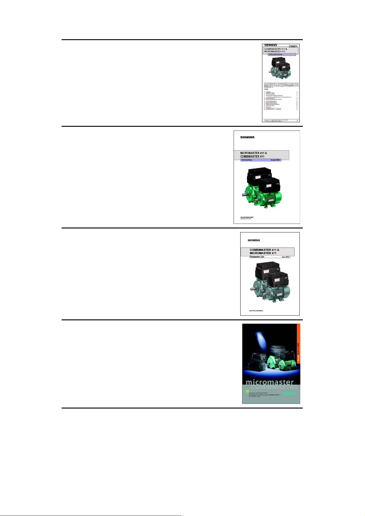
Getting Started Guide
Provides for Quick Commissioning of the Inverter.
Operating Instructions
Gives information about features of the MICROMASTER
411 / COMBIMASTER 411, Installation, Commissioning,
Control modes, System Parameter structure,
Troubleshooting, Specifications and available options of the
MICROMASTER 411 / COMBIMASTER 411.
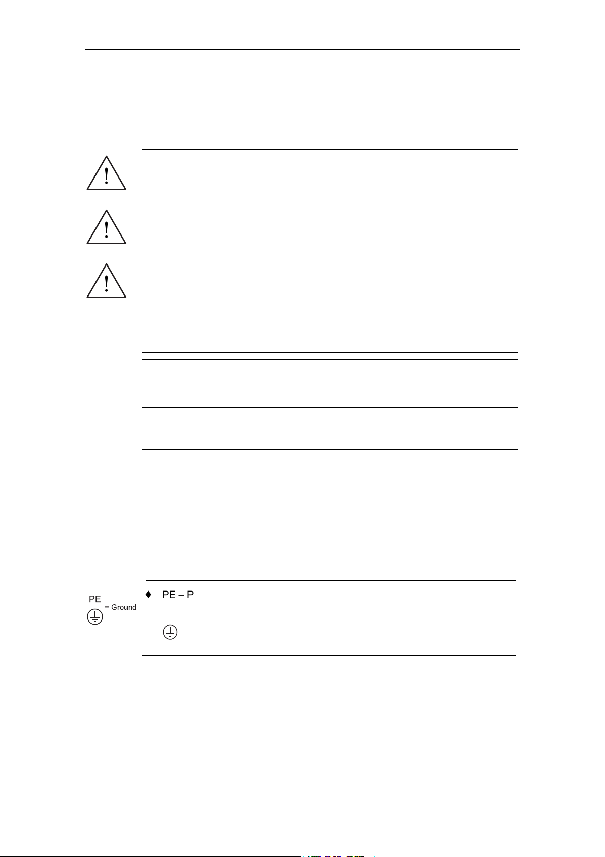
Parameter List
The Parameter List contains the description of all
Parameters structured in functional order and a detailed
description. The Parameter list also includes a series of
function plans.
Catalogues
In the catalogue you will find all the necessary information
to select an appropriate inverter, as well as Operator
Panels and Communication Options.
Page 3

1
Overview
MICROMASTER 411 &
COMBIMASTER 411
Operating Instructions
User Documentation
Installation
Commissioning
Using the
COMBIMASTER 411
System Parameters
Troubleshooting
2
3
4
5
6
Valid for Release Issue 03/01
Inverter Type Control Version
MICROMASTER 411 & 1.2
COMBIMASTER 411
Specifications
Options
Electro-Magnetic
Compatibility
Engineering
Information
Appendices
7
8
9
10
A
B
C
Issue 03/01
Index
Page 4

Further information is available on the Internet under:
http://www.siemens.de/micromaster
Approved Siemens Quality for Software and Training
is to DIN ISO 14001, Reg. No. 2160-01
The reproduction, transmission or use of this document,
or its contents is not permitted unless authorized in
writing. Offenders will be liable for damages. All rights
including rights created by patent grant or registration of a
utility model or design are reserved.
© Siemens AG 2002. All Rights Reserved.
MICROMASTER® is a registered trademark of Siemens.
MICROMASTER 411 & COMBIMASTER 411 Operating Instructions
4
Other functions not described in this document may be
available. However, this fact shall not constitute an
obligation to supply such functions with a new control, or
when servicing.
We have checked that the contents of this document
correspond to the hardware and software described.
There may be discrepancies nevertheless, and no
guarantee can be given that they are completely identical.
The information contained in this document is reviewed
regularly and any necessary changes will be included in
the next edition. We welcome suggestions for
improvement.
Siemens handbooks are printed on chlorine-free paper
that has been produced from managed sustainable
forests. No solvents have been used in the printing or
binding process.
Document subject to change without prior notice.
Siemens-Aktiengesellschaft
6SE6400-5CA00-0BP0
Page 5

Issue 03/01 Definitions and Warnings
Foreword
User Documentation
WARNING
Before installing and commissioning, you must read the safety instructions and
warnings carefully and all the warning labels attached to the equipment. Make
sure that the warning labels are kept in a legible condition and replace missing or
damaged labels.
Information is also available from:
Technical Support Nürnberg
Tel: +49 (0) 180 5050 222
Fax: +49 (0) 180 5050 223
Email: techsupport@ad.siemens.de
Monday to Friday: 7:00 am to 5:00 pm (Central European Time)
Internet Home Address
Customers can access technical and general information at:
http://www.siemens.de/micromaster
Contact address
Should any questions or problems arise while reading this manual, please contact
the Siemens office concerned using the form provided at the back this manual.
MICROMASTER 411 & COMBIMASTER 411 Operating Instructions
6SE6400-5CA00-0BP0
5
Page 6
Definitions and Warnings Issue 03/01
f
Definitions and Warnings
DANGER
indicates an immiently hazardous situation which, if not avoided, will result in death
or serious injury.
WARNING
indicates a potentially hazardous situation which, if not avoided, could result in
death or serious injury.
CAUTION
used with the safety alert symbol indicates a potentially hazardous situationwhich, i
not avoided, may result in minor or moderate injury.
PE
= Ground
CAUTION
used without safety alert symbol indicates a potentially hzardous situation which, if
not avoided, may result in a property demage.
NOTICE
indicates a potential situation which, if not avoided, may result in an undesireable
result or state.
NOTE
For the purpose of this documentation, "Note" indicates important information
relating to the product or highlights part of the documentation for special attention.
Qualified personnel
For the purpose of this Instruction Manual and product labels, a "Qualified
person" is someone who is familiar with the installation, mounting, start-up and
operation of the equipment and the hazards involved.
He or she must have the following qualifications:
1. Trained and authorized to energize, de-energize, clear, ground and tag
circuits and equipment in accordance with established safety procedures.
2. Trained in the proper care and use of protective equipment in accordance
with established safety procedures.
3. Trained in rendering first aid.
♦ PE – Protective Earth uses circuit protective conductors sized for short circuits
where the voltage will not rise in excess of 50 Volts. This connection is
normally used to ground the inverter.
♦
- Is the ground connection where the reference voltage can be the same
as the Earth voltage. This connection is normally used to ground the motor.
Use for intended purpose only
The equipment may be used only for the application stated in the manual and only
in conjunction with devices and components recommended and authorized by
Siemens.
MICROMASTER 411 & COMBIMASTER 411 Operating Instructions
6
6SE6400-5CA00-0BP0
Page 7

Issue 03/01 Safety Instructions
Safety Instructions
The following Warnings, Cautions and Notes are provided for your safety and as a
means of preventing damage to the product or components in the machines
connected. This section lists Warnings, Cautions and Notes, which apply generally
when handling COMBIMASTER 411 & MICROMASTER 411 Inverters, classified
as General, Transport & Storage, Commissioning, Operation, Repair and
Dismantling & Disposal.
Specific Warnings, Cautions and Notes that apply to particular activities are
listed at the beginning of the relevant chapters and are repeated or supplemented
at critical points throughout these chapters.
Please read the information carefully, since it is provided for your personal
safety and will also help prolong the service life of your COMBIMASTER 411
& MICROMASTER 411 Inverter and the equipment you connect to it.
General
WARNING
This equipment contains dangerous voltages and controls potentially
dangerous rotating mechanical parts. Non-compliance with Warnings or
failure to follow the instructions contained in this manual can result in loss of
life, severe personal injury or serious damage to property.
Only suitable qualified personnel should work on this equipment, and only after
becoming familiar with all safety notices, installation, operation and
maintenance procedures contained in this manual. The successful and safe
operation of this equipment is dependent upon its proper handling, installation,
operation and maintenance.
Risk of electric shock. The DC link capacitors remain charged for five minutes
after power has been removed. It is not permissible to open the equipment
until 5 minutes after the power has been removed.
HP ratings are based on the Siemens 1LA motors and are given for guidance
only; they do not necessarily comply with UL or NEMA HP ratings.
Do not operate the equipment in direct sunlight.
CAUTION
Children and the general public must be prevented from accessing or
approaching the equipment!
This equipment may only be used for the purpose specified by the
manufacturer. Unauthorized modifications and the use of spare parts and
accessories that are not sold or recommended by the manufacturer of the
equipment can cause fires, electric shocks and injuries.
MICROMASTER 411 & COMBIMASTER 411 Operating Instructions
6SE6400-5CA00-0BP0
7
Page 8

Safety Instructions Issue 03/01
NOTICE
Keep these operating instructions within easy reach of the equipment and
make them available to all users
Whenever measuring or testing has to be performed on live equipment, the
regulations of Safety Code VBG 4.0 must be observed, in particular § 8
“Permissible Deviations when Working on Live Parts”. Suitable electronic tools
should be used.
Before installing and commissioning, please read these safety instructions and
warnings carefully and all the warning labels attached to the equipment. Make
sure that the warning labels are kept in a legible condition and replace missing
or damaged labels.
Transport & Storage
WARNING
Correct transport, storage, erection and mounting, as well as careful operation
and maintenance are essential for proper and safe operation of the equipment.
Use the lifting eyes provided if a motor has to be lifted.
Do not lift machine sets by suspending the individual machines! Always check
the capacity of the hoist before lifting any equipment.
Do not paint over the black case finish of the inverter, as this will affect the
unit’s thermal performance.
CAUTION
Protect the inverter against physical shocks and vibration during transport and
storage. Also be sure to protect it against water (rainfall) and excessive
temperatures (see Table on page 94).
MICROMASTER 411 & COMBIMASTER 411 Operating Instructions
8
6SE6400-5CA00-0BP0
Page 9

Issue 03/01 Safety Instructions
Commissioning
WARNING
Work on the device/system by unqualified personnel or failure to comply with
warnings can result in severe personal injury or serious damage to material.
Only suitably qualified personnel trained in the setup, installation,
commissioning and operation of the product should carry out work on the
device/system.
Only permanently wired input power connections are allowed. This equipment
must be grounded (IEC 536 Class 1, NEC and other applicable standards).
If a Residual Current-operated protective Device (RCD) is to be used, it must
be an RCD type B.
Machines with a three-phase power supply, fitted with EMC filters, must not be
connected to a supply via an ELCB (Earth Leakage Circuit-Breaker - see DIN
VDE 0160, section 5.5.2 and EN50178 section 5.2.11.1).
The following terminals can carry dangerous voltages even if the inverter is
inoperative:
♦ power supply terminals L1, L2, L3
♦ motor terminals U, V, W
♦ additionally the terminals DC+, DC-
This equipment must not be used as an ‘Emergency Stop mechanism’ (see
EN 60204, 9.2.5.4).
The inverter electronics contain static sensitive devices therefore precautions
must be taken against electrostatic discharge (ESD) when handling the
separated inverter assembly. These include not touching the internal surfaces
of the inverter and ensuring that personnel are earthed while handling the unit.
The terminal housing, including Filter and I/O modules, contain no sensitive
components and therefore no special handling precautions are required when
separated.
CAUTION
The connection of power, motor and control cables to the inverter must be carried
out as shown in Figure 2-10 respectively, to prevent inductive and capacitive
interference from affecting the correct functioning of the inverter.
MICROMASTER 411 & COMBIMASTER 411 Operating Instructions
6SE6400-5CA00-0BP0
9
Page 10

Safety Instructions Issue 03/01
Operation
WARNING
MICROMASTER 411/COMBIMASTER 411 operate at high voltages.
When operating electrical devices, it is impossible to avoid applying
hazardous voltages to certain parts of the equipment.
Emergency Stop facilities according to EN 60204 IEC 204 (VDE 0113) must
remain operative in all operating modes of the control equipment. Any
disengagement of the Emergency Stop facility must not lead to uncontrolled or
undefined restart.
Wherever faults occurring in the control equipment can lead to substantial
material damage or even grievous bodily injury (i.e. potentially dangerous
faults), additional external precautions must be taken or facilities provided to
ensure or enforce safe operation, even when a fault occurs (e.g. independent
limit switches, mechanical interlocks, etc.).
Certain parameter settings may cause the inverter to restart automatically
after an input power failure.
This equipment is capable of providing internal motor overload protection.
Refer to P0610 (level 3) and P0335, I
protection can also be provided using an external PTC via a digital input.
This equipment is suitable for use in a circuit capable of delivering not more
than 10,000 symmetrical amperes (rms), for a maximum voltage of 460 V
when protected by an H or K Class fuse (see Section 7.5).
This equipment must not be used as an ‘emergency stop mechanism’ (see EN
60204, 9.2.5.4)
2
t is ON by default. Motor overload
Repair
WARNING
Repairs on equipment may only be carried out by Siemens Service, by repair
centers authorized by Siemens or by qualified personnel who are thoroughly
acquainted with all the warnings and operating procedures contained in this
manual.
Any defective parts or components must be replaced using parts contained in
the relevant spare parts list.
Disconnect the power supply before opening the equipment for access.
Dismantling & Disposal
NOTE
Inverter packaging is re-usable. Retain the packaging for future use or return it
to the manufacturer.
Easy-to-release screw and snap connectors allow you to break the unit down
into its component parts. You can then re-cycle these component parts,
dispose of them in accordance with local requirements or return them to
the manufacturer.
MICROMASTER 411 & COMBIMASTER 411 Operating Instructions
10
6SE6400-5CA00-0BP0
Page 11

Issue 03/01 Table of Contents
Table of Contents
1
1.1
1.2
2
2.1
2.2
2.3
2.4
2.5
3
3.1
3.2
3.3
3.4
4
4.1
4.2
4.3
4.4
4.5
Overview ................................................................................................................15
MICROMASTER 411 / COMBIMASTER 411 ......................................................... 16
Design Features ...................................................................................................... 17
Installation .............................................................................................................19
Installation after a Period of Storage....................................................................... 21
Ambient operating conditions..................................................................................22
Mechanical Installation MICROMASTER 411......................................................... 23
Mechanical Installation COMBIMASTER 411......................................................... 30
Electrical Installation................................................................................................ 33
Commissioning .....................................................................................................41
Block Diagram ......................................................................................................... 43
General Information................................................................................................. 44
Commissioning Procedure Overview ...................................................................... 45
General operation.................................................................................................... 56
Using the MICROMASTER 411 / COMBIMASTER 411 ....................................... 61
Frequency Setpoint ................................................................................................. 62
Command Sources (P0700).................................................................................... 63
OFF and Braking Functions .................................................................................... 63
Control Modes (P1300) ........................................................................................... 65
Faults and warnings ................................................................................................ 65
5
5.1
5.2
5.3
6
6.1
6.2
6.3
7
7.1
7.2
7.3
7.4
7.5
System Parameters...............................................................................................67
Introduction to System Parameters.........................................................................68
Parameter Structure................................................................................................ 69
Parameter List (short form) ..................................................................................... 70
Troubleshooting .................................................................................................... 79
Troubleshooting with the Inverter LED.................................................................... 80
Troubleshooting with the Basic Operator Panel...................................................... 80
Faults and Alarms ...................................................................................................81
Specifications ........................................................................................................ 93
Technische Daten ...................................................................................................94
Case Size Rating Information .................................................................................95
Tightening Torque, Cable cross sections for Power Supply and Motor Terminals. 96
Tightening Torque for Fixing Screws ......................................................................96
Fuses and Circuit Breakers.....................................................................................97
MICROMASTER 411 & COMBIMASTER 411 Operating Instructions
6SE6400-5CA00-0BP0
11
Page 12

Table of Contents Issue 03/01
8
8.1
8.2
8.3
8.4
8.5
8.6
8.7
8.8
8.9
8.10
9
9.1
10
10.1
10.2
10.3
10.4
10.5
10.6
10.7
10.8
10.9
10.10
10.11
10.12
10.13
10.14
10.15
Options...................................................................................................................99
MICROMASTER 411/COMBIMASTER 411 User Options ..................................... 99
MICROMASTER 411/COMBIMASTER 411 Programming Options ..................... 100
Basic Operator Panel (BOP) / Advanced Operator Panel (AOP) ......................... 101
PROFIBUS Module ............................................................................................... 102
EM Brake Module.................................................................................................. 103
MICROMASTER 411 Operator Panel Mounting Kit.............................................. 104
PC to Inverter Connection Kit................................................................................ 105
PC to AOP Connection Kit ....................................................................................106
Door Mounting Kit for Single Inverter control ........................................................ 107
Wall Mounting Kit for MICROMASTER 411..........................................................108
Electro-Magnetic Compatibility (EMC).............................................................. 109
Electro-Magnetic Compatibility (EMC) .................................................................. 110
Engineering Information..................................................................................... 115
Current Limit and Overload Operation .................................................................. 116
Control and Operating Modes............................................................................... 120
Braking ..................................................................................................................132
Derating Factors.................................................................................................... 135
Thermal Protection and Automatic De-rating........................................................137
Operation from Unearthed Supplies...................................................................... 137
Lifetime of Inverters............................................................................................... 137
Working with Binary Connectors (BiCo)................................................................ 138
Harmonic Currents ................................................................................................ 145
Use of MM4 Input Chokes..................................................................................... 146
Power Losses........................................................................................................146
Shock and Vibration .............................................................................................. 147
PROFIBUS ............................................................................................................ 148
PROFIBUS Module ............................................................................................... 149
Variant Independent Options ................................................................................152
Appendices...............................................................................................................................155
A
B
C
D
MICROMASTER 411 & COMBIMASTER 411 Operating Instructions
12
Applicable Standards .........................................................................................155
List of Abbreviations........................................................................................... 156
MICROMASTER 411 / COMBIMASTER 411 Parts Identification.....................157
Index ..................................................................................................................... 158
6SE6400-5CA00-0BP0
Page 13

Issue 03/01 Table of Contents
List of Tables
Table 2-1 MICROMASTER 411 Dimension Detail................................................................................26
Table 2-2 Gland Plate Detail.................................................................................................................28
Table 3-1 Ramp Time Adjustment Jumpers..........................................................................................46
Table 3-2 Ramp Time Jumper Behaviour .............................................................................................47
Table 3-3 Control Circuit Jumper Settings ............................................................................................48
Table 3-4 Control Circuit Jumper Behaviour .........................................................................................48
Table 3-5 Default Settings for BOP Operation ......................................................................................50
Table 6-1 Inverter LED Indication .........................................................................................................80
Table 7-1 MICROMASTER 411 / COMBIMASTER 411, Leistungsdaten .............................................94
Table 7-2 Case Size B ..........................................................................................................................95
Table 7-3 Case Size C..........................................................................................................................95
Table 7-4 Power Supply & Motor Terminal Wire Sizes/Tightening Torques .........................................96
Table 7-5 Fixing Screw Recommended Tightening Torque ..................................................................96
Table 7-6 MICROMASTER 411/COMBIMASTER 411 Fuses and Circuit Breakers .............................97
Table 8-1 Key to Programming Options..............................................................................................100
Table 9-1 Environment - General Industrial ........................................................................................111
Table 9-2 Environment - Filtered Industrial .........................................................................................111
Table 9-3 Environment - Filtered for Residential, Commercial and Light Industry ..............................112
Table 9-4 EMC Compliance Table......................................................................................................113
Table 9-5 MICROMASTER 411 Measured Results ............................................................................113
Table 10-1 Measured Current Monitoring Accuracy..............................................................................117
Table 10-2 Trip Levels ..........................................................................................................................119
Table 10-3 Derating with Switching Frequencies..................................................................................136
Table 10-4 BiCo Connections (r0019 to r0054) ....................................................................................141
Table 10-5 BiCo Connections (r0055 to r1119) ....................................................................................142
Table 10-6 BiCo Connections (r1170 to r2050) ....................................................................................143
Table 10-7 BiCo connections (r2053 to r2294) .....................................................................................144
Table 10-8 Three Phase 400 V Connection..........................................................................................145
Table 10-9 Maximum Cable Lengths for Data Transfer Rates..............................................................150
Table 10-10 Technical data – 411 PROFIBUS Module...........................................................................151
Table 10-11 PROFIBUS Ordering information........................................................................................151
MICROMASTER 411 & COMBIMASTER 411 Operating Instructions
6SE6400-5CA00-0BP0
13
Page 14

Table of Contents Issue 03/01
List of Illustrations
Figure 1-1 MICROMASTER 411 and COMBIMASTER 411 Variable Frequency Inverters....................18
Figure 2-1 Forming.................................................................................................................................21
Figure 2-2 MICROMASTER 411, Internal Layout ..................................................................................25
Figure 2-3 MICROMASTER 411 Case Size B Dimensions....................................................................26
Figure 2-4 MICROMASTER 411 Case Size C Dimensions ...................................................................26
Figure 2-5 Cable Glands........................................................................................................................27
Figure 2-6 Installation of Cable Gland....................................................................................................27
Figure 2-7 MICROMASTER 411 Gland Dimensions..............................................................................28
Figure 2-8 COMBIMASTER 411 Case Size B Dimensional Detail.........................................................31
Figure 2-9 COMBIMASTER 411 Case Size B Dimensional Detail.........................................................32
Figure 2-10 Motor and Power Supply Connections..................................................................................36
Figure 2-11 Control Terminals .................................................................................................................37
Figure 2-12 PTC Connections..................................................................................................................38
Figure 3-1 COMBIMASTER 411 & MICROMASTER 411 Block Diagram..............................................43
Figure 3-2 MICROMASTER 411 / COMBIMASTER 411 Commissioning Guide ...................................45
Figure 3-3 Ramp Time Jumpers.............................................................................................................46
Figure 3-4 Control Circuit Jumpers ........................................................................................................48
Figure 3-5 Basic Operator Panel Controls .............................................................................................51
Figure 3-6 Changing parameters via the BOP .......................................................................................52
Figure 3-7 Typical Motor Rating Plate Example.....................................................................................55
Figure 3-8 Default Setup Terminal Connections ....................................................................................56
Figure 3-9 Connect BOP/AOP with the MICROMASTER 411 ...............................................................58
Figure 5-1 Parameter Structure with Filter (P0004)................................................................................69
Figure 10-1 Current Limit Interaction......................................................................................................117
Figure 10-2 PTC Resistor Connections..................................................................................................118
Figure 10-3 Boost-Level.........................................................................................................................120
Figure 10-4 Quick response with overshoot: P2280 = 0.30; P2285 = 0.03 s .........................................124
Figure 10-5 Quick response with overshoot, but instability:P2280 = 0.55; P2285 = 0.03 s.................... 124
Figure 10-6 Damped response: P2280 = 0.20; P2285 = 0.15 s .............................................................125
Figure 10-7 Response to 5 Hz step: L = 100 ms.................................................................................... 126
Figure 10-8 Response to 5 Hz step: T = 700 ms....................................................................................127
Figure 10-9 Step Response in PI control with P2280 = 9.84 and P2285 = 0.30 ....................................127
Figure 10-10 PI Basic Block Diagram ......................................................................................................128
Figure 10-11 Energy Saving Mode 1........................................................................................................130
Figure 10-12 Energy Saving Mode 2........................................................................................................131
Figure 10-13 Frequency Ramp Down ......................................................................................................132
Figure 10-14 DC Braking .........................................................................................................................133
Figure 10-15 Compound Braking .............................................................................................................134
Figure 10-16 Reduktionsfaktoren durch die Umgebungstemperatur........................................................135
Figure 10-17 Derating with Altitude..........................................................................................................135
Figure 10-18 Power Losses MICROMASTER 411 / COMBIMASTER 411 ..............................................146
MICROMASTER 411 & COMBIMASTER 411 Operating Instructions
14
6SE6400-5CA00-0BP0
Page 15

Issue 03/01 1 Overview
1 Overview
This Chapter contains:
A summary of the major features of the COMBIMASTER 411 & MICROMASTER
411 range.
1.1
1.2 Design Features...................................................................................................... 17
MICROMASTER 411 / COMBIMASTER 411 ......................................................... 16
MICROMASTER 411 & COMBIMASTER 411 Operating Instructions
6SE6400-5CA00-0BP0
15
Page 16

1 Overview Issue 03/01
1.1 MICROMASTER 411 / COMBIMASTER 411
The Siemens COMBIMASTER 411 & MICROMASTER 411 variable frequency (V/f)
range of inverters are used to control the speed of three phase AC induction
motors.
COMBIMASTER 411 provides for a ready to use Inverter/Motor combination unit
MICROMASTER 411 offers an Inverter for adaptation to a compatible motor with
terminal boxes of size GK030.
Inverters are available in ranges 370 W to 3.0 kW 380/480 V AC for three phase
units.
The inverters are microprocessor-controlled and use state-of-the-art Insulated Gate
BipoIar Transistor (IGBT) technology. This makes them reliable and versatile. A
special pulse-width modulation method with selectable Pulse frequency permits
quiet motor operation. Comprehensive protective functions provide excellent
inverter and motor protection.
With the factory default settings, the MICROMASTER 411 / COMBIMASTER 411 is
suitable for many variable speed applications. Using the functionally grouped
parameters, the MICROMASTER 411 / COMBIMASTER 411 can adapted to more
demanding applications.
MICROMASTER 411/COMBIMASTER 411 can be used in 'stand-alone' applications as well as being integrated into complete automation systems.
MICROMASTER 411 & COMBIMASTER 411 Operating Instructions
16
6SE6400-5CA00-0BP0
Page 17

Issue 03/01 1 Overview
1.2 Design Features
Main Characteristics
Easy installation
Easy commissioning
High starting torque with programmable starting boost
Options for remote control:
♦ Basic Operator Panel
♦ Advanced Operator Panel
♦ Serial interface (RS232)
Factory default parameter settings pre-programmed for European and North
American requirements
Output frequency (and hence motor speed) can be controlled by one of four
methods:
♦ Internal Speed Control Potentiometer
♦ Analogue setpoint (voltage or current input)
♦ Fixed frequencies via binary inputs
♦ Serial interface
Programmable signal relay output incorporated
Rugged EMC design
Fast repeatable response time to control signals
Comprehensive range of parameters enabling configuration for a wide range of
applications
Simple connection
High switching frequencies for low-noise motor operation
Detailed status information and integrated messaging functions
External options for PC communications, Basic Operator Panel (BOP),
Advanced Operator Panel (AOP), PROFIBUS communications module
Option for integrated class B-filter (interference emission class A)
Optional housing for installing PROFIBUS module and EM control module
MICROMASTER 411 & COMBIMASTER 411 Operating Instructions
6SE6400-5CA00-0BP0
17
Page 18
1 Overview Issue 03/01
Performance Characteristics
Flux Current Control (FCC) for improved dynamic response and motor control
Fast Current Limitation (FCL) for trip-free operation
Built-in DC injection brake
Compound braking to improve braking performance
Ramp function generator with programmable smoothing
Control with Proportional-Integral control function (PI)
Multi-point V/f characteristic
Protection characteristics
MICROMASTER 411: Type of protection up to IP66 (comparable to NEMA 4X)
COMBIMASTER 411: Type of protection up to IP55 (comparable to NEMA 4)
Overvoltage/undervoltage protection
Overtemperature protection for the inverter
Short-circuit protection
2
i
t thermal motor protection
PTC for motor protection, via digital input 3
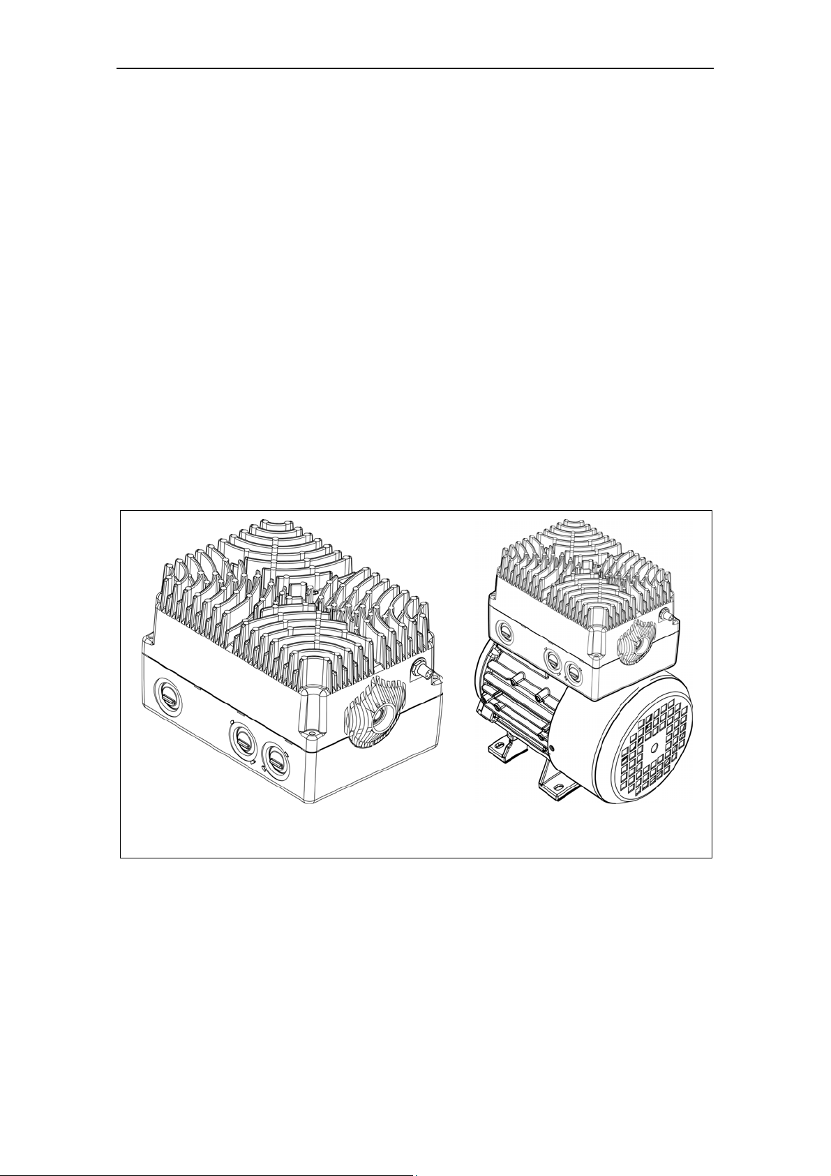
MICROMASTER 411 Variable Frequency Inverter COMBIMASTER 411 Variable
Frequency Inverter – Motor Combination
Figure 1-1 MICROMASTER 411 and COMBIMASTER 411 Variable Frequency Inverters
MICROMASTER 411 & COMBIMASTER 411 Operating Instructions
18
6SE6400-5CA00-0BP0
Page 19

Issue 03/01 2 Installation
2 Installation
This Chapter contains:
General data relating to installation
Inverter Dimensions
Wiring guidelines to minimize the effects of EMI
Details concerning electrical installation
2.1
2.2 Ambient operating conditions..................................................................................22
2.3
2.4
2.5
Installation after a Period of Storage....................................................................... 21
Mechanical Installation MICROMASTER 411......................................................... 23
Mechanical Installation COMBIMASTER 411......................................................... 30
Electrical Installation................................................................................................ 33
MICROMASTER 411 & COMBIMASTER 411 Operating Instructions
6SE6400-5CA00-0BP0
19
Page 20

2 Installation Issue 03/01
WARNING
Work on the device/system by unqualified personnel or failure to comply with
warnings can result in severe personal injury or serious damage to material.
Only suitably qualified personnel trained in the setup, installation,
commissioning and operation of the product should carry out work on the
device/system.
Only permanently wired input power connections are allowed. This equipment
must be grounded (IEC 536 Class 1, NEC and other applicable standards).
If a Residual Current-operated protective Device (RCD) is to be used, it must
be an RCD type B.
Machines with a three-phase power supply, fitted with EMC filters, must not be
connected to a supply via an ELCB (Earth Leakage Circuit-Breaker EN50178
Section 5.2.11.1).
The following terminals can carry dangerous voltages even if the inverter is
inoperative:
- power supply terminals L1, L2, L3
- motor terminals U, V, W
- additionally the terminals DC+, DC-
Always wait 5 minutes to allow the unit to discharge after switching off before
carrying out any installation work.
This equipment must not be used as an ‘emergency stop mechanism’ (see EN
60204, 9.2.5.4)
The minimum size of the earth-bonding conductor must be equal to or greater
than the cross-section of the power supply cables.
CAUTION
The connection of power and motor cables to the inverter must be carried out as
shown in Figure 2-10 to prevent inductive and capacitive interference from
affecting the correct functioning of the inverter.
MICROMASTER 411 & COMBIMASTER 411 Operating Instructions
20
6SE6400-5CA00-0BP0
Page 21
Issue 03/01 2 Installation
2.1 Installation after a Period of Storage
Following a prolonged period of storage, you must reform the capacitors in the
inverter. The requirements are listed below.
Voltage
[%]
100
75
50
0,5 1
Figure 2-1 Forming
Storage period less than 1 year:
Storage period 1 to 2 years:
Storage period 2 to 3 years:
Storage period 3 and more years:
2468
No action necessary
Prior to energizing, connect to
voltage for one hour
Prior to energizing, form
according to the curve
Prior to energizing, form
according to the curve
Time t [h]
MICROMASTER 411 & COMBIMASTER 411 Operating Instructions
6SE6400-5CA00-0BP0
21
Page 22

2 Installation Issue 03/01
2.2 Ambient operating conditions
Temperature
Operating temperature –10 °C to +40 °C
(power reduction at +50 °C see Section 10.4.1).
Humidity Range
≤ 99 %, Non-condensing
Altitude
If the inverter is to be installed at an altitude > 1000 m, derating will be required.
Refer to Section 10.4.2 for details.
Shock
Refer to the notes in Section 10.12.
Electromagnetic Radiation
Do not install the inverter near sources of electromagnetic radiation.
Overheating
MICROMASTER 411 / COMBIMASTER 411 are cooled by natural convection.
Mount the inverter with the heatsink fins above to ensure optimum cooling.
Mounting the inverter with the heatsink upside down is not allowed.
Ensure that airflow around the inverter housing is not obstructed. Allow 100 mm
clearance above and below the inverter.
MICROMASTER 411 & COMBIMASTER 411 Operating Instructions
22
6SE6400-5CA00-0BP0
Page 23

Issue 03/01 2 Installation
2.3 Mechanical Installation MICROMASTER 411
WARNING
♦ This equipment must be grounded.
♦ To ensure safe operation of the equipment, it must be installed and
commissioned by qualified personnel in full compliance with the warnings laid
down in these operating instructions.
♦ Take particular note of the general and regional installation and safety
regulations regarding work on dangerous voltage installations (e.g. EN
50178), as well as the relevant regulations regarding the correct use of tools
and personal protective gear.
♦ The Power supply, DC and motor terminals, can carry dangerous voltages
even if the inverter is inoperative; wait 5 minutes to allow the unit to
discharge after switching off before carrying out any installation work.
2.3.1 Preparation
Remove the MICROMASTER 411 installation kit from the packing. Check packing
box contents against the advice note supplied.
4
The installation kit should comprise the following items:
1. Inverter cover
2. Terminal Housing
3. Filter Module & screws (captive)
4. Input – Output Board & screws (captive)
5. Earth Lead
6. 10 Off Terminal Jumpers
7. Getting Started Guide and CD
8. 2 off Glands M25 IP68 withO-ring
9. 2 off M25 sealing plugs
10. 2 off M25 Gland Fixing Plates
11. 2 off U-clamp & screws (for earth/ground connection)
12. 4 off M4 Inverter to Motor fixing screws
(CSC only: additional 4 off M5 screws)
13. Motor Cable Sheath
14. 1 off Motor Gasket (CSC only: additional 1 off Motor Gasket)
15. 1 off M12 connector blanking plug
Any defective or missing items should be reported immediately to your local
Siemens Distributor or Sales Office.
MICROMASTER 411 & COMBIMASTER 411 Operating Instructions
6SE6400-5CA00-0BP0
23
Page 24

2 Installation Issue 03/01
2.3.2 Installation Procedure
NOTE (MICROMASTER 411 ONLY):
Prior to installation it may be necessary to fit an Adaptation Plate to a non-Siemens
motor. The Adaptation Plate is prepared by the respective motor manufacturer.
Normally the Adaptation Plate makes use of the existing motor gasket.
Physical dimensions and characteristics for installation are given in Section:
2.3.3 for MICROMASTER 411
2.4.2 for COMBIMASTER 411
With the product items removed from their packaging carry out the following
installation procedure.
1. Separate the two halves (Inverter Cover and Terminal Housing).
2. Remove the Filter Module and I/O board.
CAUTION
Do not knock out cable gland blanking plates unless the inverter ‘electronics’ (Filter
& I/O boards) have been removed.
3. Remove the cable gland blanking plates (knockouts) as required (see Figure
2-6). The preferred gland arrangements are shown in the General Layout
Diagram Figure 2-5.
4. Fit cable glands to terminal housing, ensuring the O-rings are fitted to ensure
the seal is maintained.
5. Fit the earth lead to the earth terminal within the motor terminal box. If required
fit a Motor PTC cable (not supplied).
6. Run all cables between the motor and inverter within the cable sheath
provided.
7. Using the appropriate motor gasket, fix the terminal housing to the motor.
Screw fixing torque values are: 1.5 Nm – M4 and 2.5 Nm – M5.
8. Insert power and control cables through glands and make off ends as required.
9. Fit the Filter board (see Figure 2-2).
10. Secure Filter board with M3 taptite screws (torque values see Table 7-5 ).
11. Connect power cables as detailed in Section 2.5.2.
12. Connect up the motor terminals in either star or delta configuration as
explained in Section 2.5.2.
13. Connect control wires as detailed in Section 2.5.3.
14. Fit the I/O board (see Figure 2-2).
15. Secure I/O board with M3 taptite screws. (torque values see Table 7-4 ).
16. Fit jumpers as required – see Section 3.3.
17. Place the inverter cover onto the assembled terminal housing.
18. Secure the inverter cover with the four M5 captive screws.
Use either a 4-5 mm flat bladed screwdriver or a 2pt Pozidrive Head
screwdriver.
MICROMASTER 411 & COMBIMASTER 411 Operating Instructions
24
6SE6400-5CA00-0BP0
Page 25
Issue 03/01 2 Installation
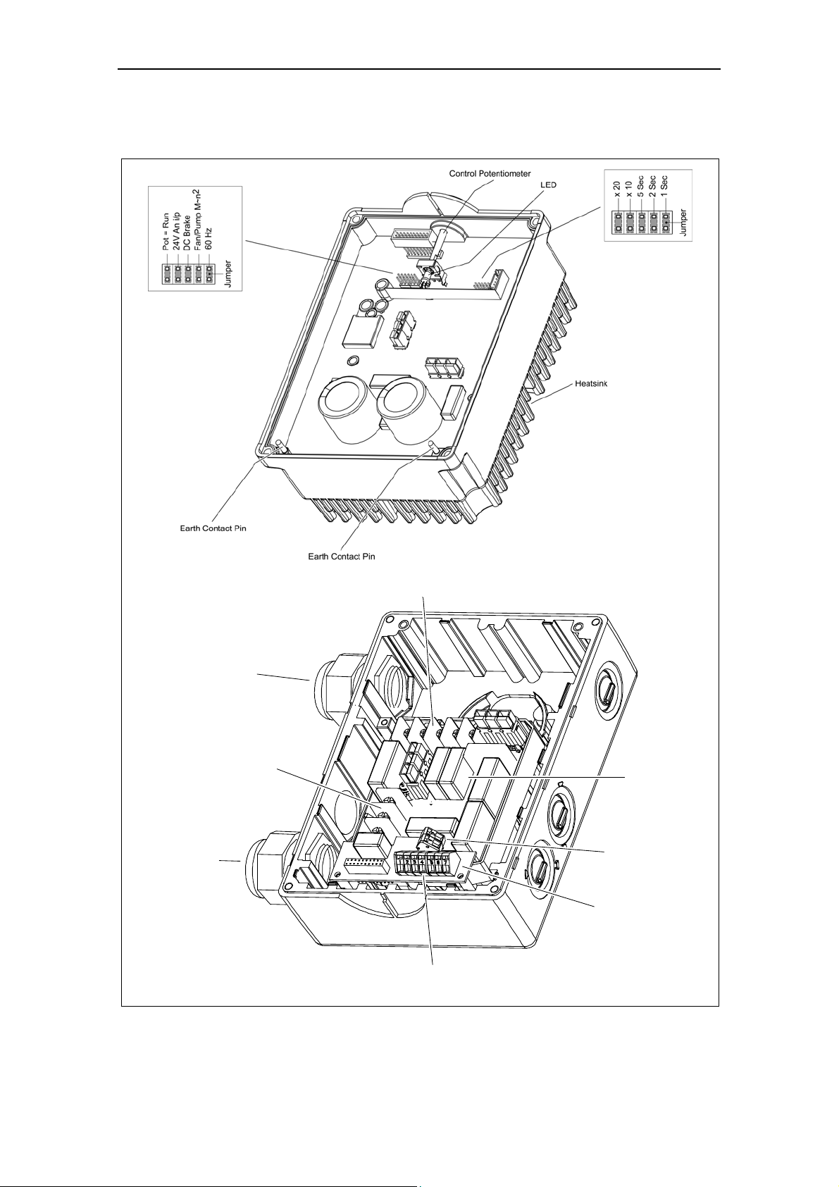
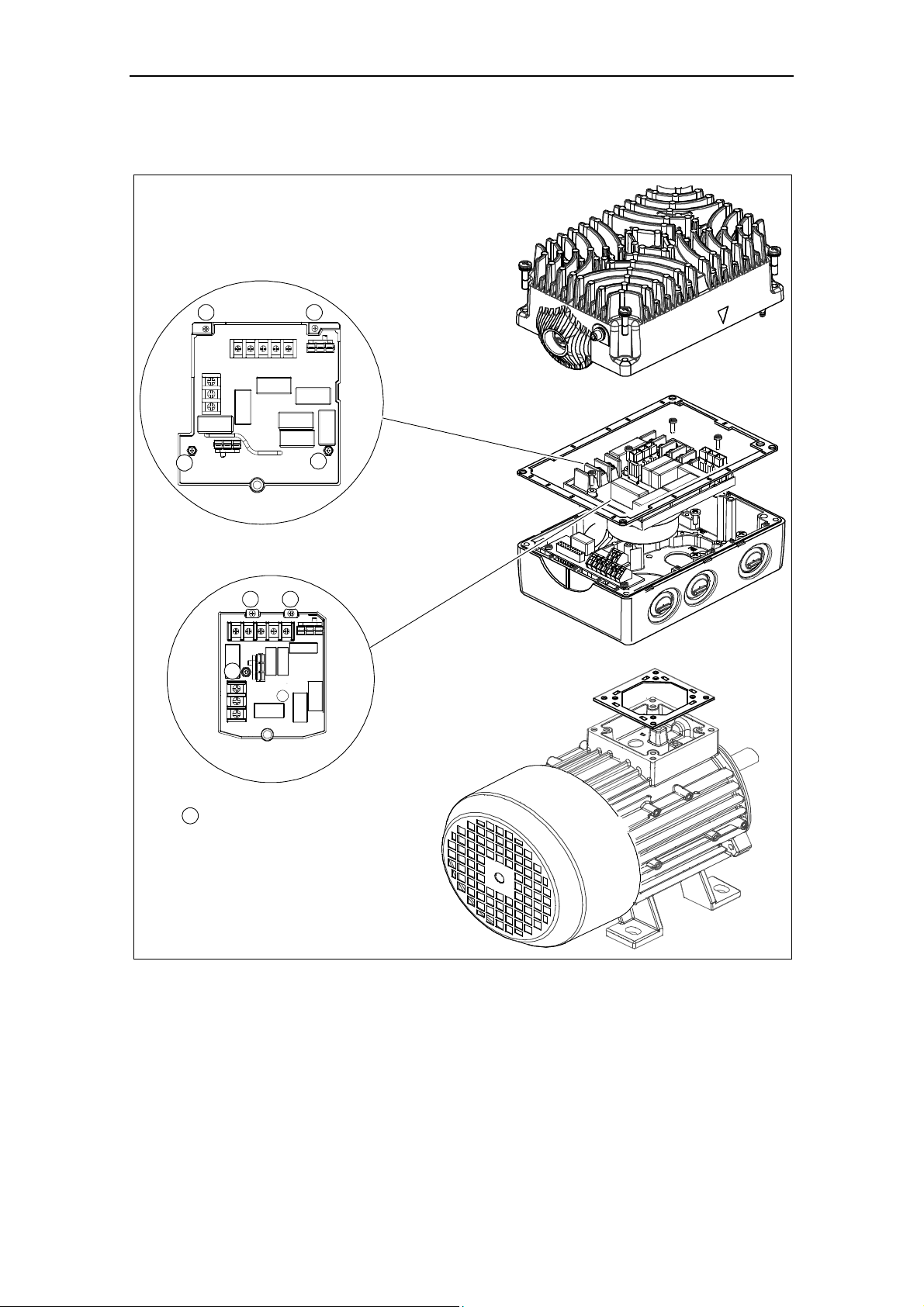
2.3.3 Layout of MICROMASTER 411
(Power Supply)
Cable Gland
(Control)
Cable Gland
Power Supply
Terminals
Inverter Cover (CSB)
Motor Terminals
Filter Module
Output Relay
Terminals
Input/Output
Board
Control Terminals
Terminal Housing (CSB) (Cable glands shown in preferred positions)
Figure 2-2 MICROMASTER 411, Internal Layout
MICROMASTER 411 & COMBIMASTER 411 Operating Instructions
6SE6400-5CA00-0BP0
25
Page 26
2 Installation Issue 03/01
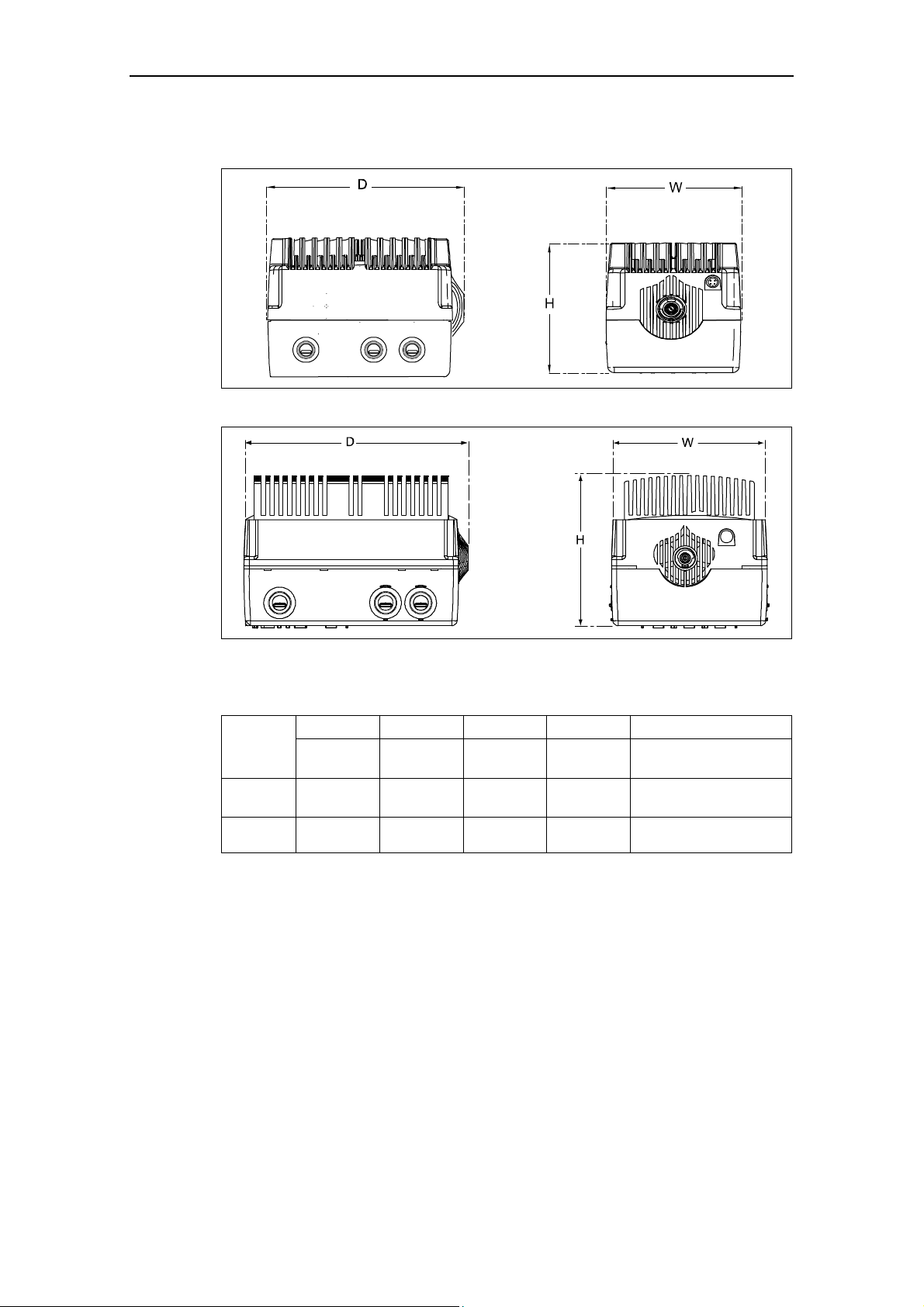
MICROMASTER 411 Dimensional Detail
Figure 2-3 MICROMASTER 411 Case Size B Dimensions
Figure 2-4 MICROMASTER 411 Case Size C Dimensions
Table 2-1 MICROMASTER 411 Dimension Detail
Case
Size
B
C
Height (H) Width (W) Depth (D) Weight Power Range
mm
(Inches)
135.6
(5.31)
170.6
(6.61)
mm
(Inches)
154
(6.06)
177
(6.97)
mm
(Inches)
222
(8.74)
255
(10.04)
kg
(lbs)
4.9
(10.77)
7.4
(16.34)
kW
(hp)
0.37 – 1.5
(0.5 – 2.0)
2.2 – 3.0
(3.0 – 4.0)
MICROMASTER 411 & COMBIMASTER 411 Operating Instructions
26
6SE6400-5CA00-0BP0
Page 27
Issue 03/01 2 Installation
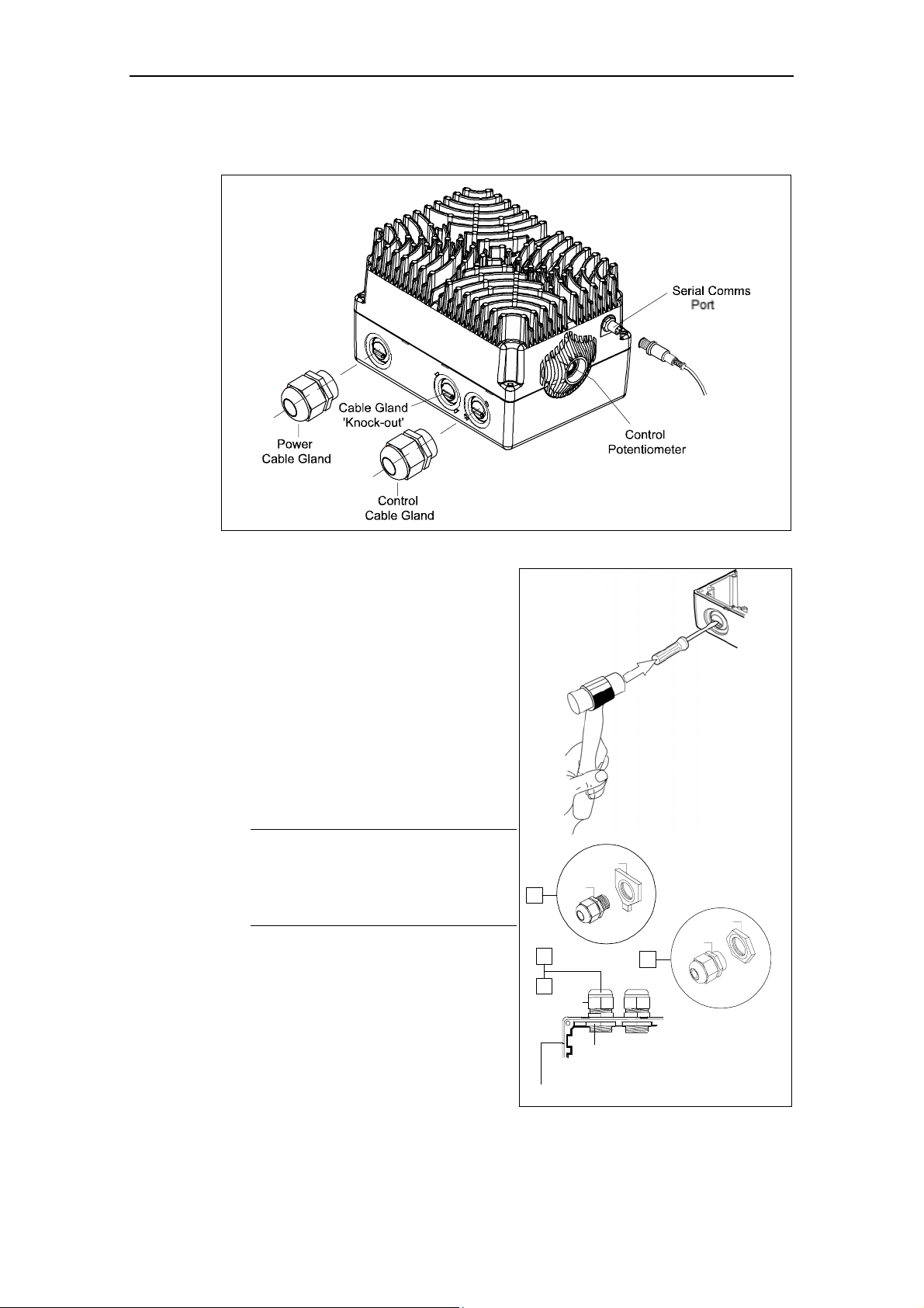
2.3.4 Installation of Cable Glands
Figure 2-5 Cable Glands
Before power and control cables can be
connected to their respective circuits it will
first be necessary to fit the cable glands
supplied.
Each gland should be located ideally to
allow for convenient cable runs to the
terminals located on the Filter and I/O
boards.
1. Using a hammer and a flat-head
screwdriver as shown in Figure 2-6
strike the gland plate or ‘knockout’ to
obtain a clearance for the 25 mm
cable gland.
NOTE
Care must be taken to prevent
damage to the Terminal Housing, as
this may affect the IP rating of the
inverter.
2. Remove any sharp edges from the
gland area and any swarf from the
terminal housing.
3. After the knockout has been removed
it should be safely discarded and the
cable glands fitted as shown in Figure
2-6.
1
Terminal Housing
A
1
2
A
B
B
B
A
2
Figure 2-6 Installation of Cable Gland
MICROMASTER 411 & COMBIMASTER 411 Operating Instructions
6SE6400-5CA00-0BP0
27
Page 28
2 Installation Issue 03/01
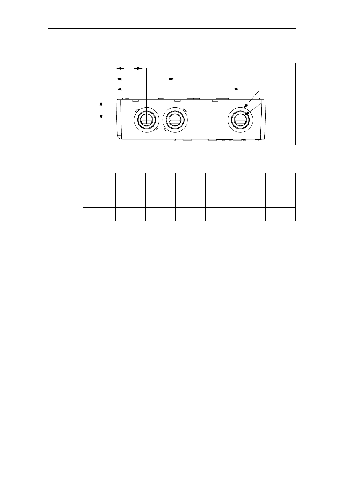
MICROMASTER 411 – Cable Gland Dimensions.
GW1
GW2
GW3
GH
Figure 2-7 MICROMASTER 411 Gland Dimensions
Table 2-2 Gland Plate Detail
GW1 GW2 GW3 GH GD1 GD2
Case Size
B
C
mm
(inch)
42,9
(1,68)
43,0
(1,69)
mm
(inch)
82,9
(3,26)
83,0
(3,27)
mm
(inch)
175,0
(6,89)
203,4
(8,01)
mm
(inch)
27,6
(1,09)
38,3
(1,51)
mm
(inch)
35
(1,38)
36
(1,42)
GD1
GD2
mm
(inch)
26
(1,02)
26
(1,02)
MICROMASTER 411 & COMBIMASTER 411 Operating Instructions
28
6SE6400-5CA00-0BP0
Page 29
Issue 03/01 2 Installation
2.3.5 Mounting the Inverter on a Siemens Motor
1 1
1
1
FSC
1 1
1
FSB
Filter Board Captive Retaining Screws
1
2.3.6 Wall Mounting the Inverter
Wall mounting of MICROMASTER 411 see Section 8.10.
MICROMASTER 411 & COMBIMASTER 411 Operating Instructions
6SE6400-5CA00-0BP0
29
Page 30

2 Installation Issue 03/01
2.4 Mechanical Installation COMBIMASTER 411
2.4.1 COMBIMASTER 411 Installation Procedure
Ensure that any lifting eyes are tightened down prior to moving the
COMBIMASTER into position.
Use the lifting eyes provided if a motor has to be lifted. Always check the capacity
of the hoist before lifting any equipment.
WARNING
Do not attempt to lift the COMBIMASTER 411 using the inverter housing as this
could result in severe damage to the inverter or motor and possibly severe
personal injury.
Move the COMBIMASTER 411 into the required position and secure by inserting
suitable foundation bolts through the motor feet (see Figure 2-8 and Figure 2-9).
Allow adequate clearance of 100 mm minimum around the unit to provide for air
circulation.
COMBIMASTER 411 is supplied with a Power Supply Gland fitted to the preferred
cable entry port. Should it become necessary to select other cable entry ports for
either Power supply or Control then cable glands must be removed and the
redundant port blanked off. Always remember to remove Inverter electronics before
knocking out blanking plates. Blank off all redundant cable ports.
CAUTION
Do not knock out cable gland blanking plates unless inverter ‘electronics’ (Filter &
I/O boards) have been removed
Carry out the following checks prior to commissioning the COMBIMASTER 411:
1. The rotor is correctly aligned and free to rotate without obstruction.
2. Transmission elements are adjusted correctly (e.g. belt tensioned) and suitable
for the given operating conditions.
3. All electrical connections, mounting screws and connecting elements tightened
and fitted correctly.
4. Protective conductors installed properly
5. Any auxiliary equipment that might be fitted (e.g. mechanical brake) is in
working order.
6. Protection guards are installed around all moving and live parts and any
relevant safety notices displayed.
MICROMASTER 411 & COMBIMASTER 411 Operating Instructions
30
6SE6400-5CA00-0BP0
Page 31

Issue 03/01 2 Installation
2.4.2 COMBIMASTER 411 Dimensional Detail
COMBIMASTER 411- Case Size B
27.6
Rear lip of Terminal Housing
taken as reference point for
Gland Measurements
222
36 128 168
Frame size 90S and 90L
have feet with 2 holes
each at the non-drive end.
154
135.6
Frame
Size
71M
80M
90S
Motor Poles
1LA7 070
1LA7 073
2 - 4
1LA7 080
2 - 4
1LA7 083
1LA7 090
1LA7 096
2 - 4
TL TW TH MF1 MF2 MF3 MS1 MS2 MB1
240
(9.4)
274
(10.8)
132
(5.2)
150
(5.9)
278.6
(11.0)
296.6
(11.7)
45
(1.8)
50
(2.0)
90
(3.5)
100
(3.9)
309
(12.2)
331
(13.0)
165
(6.5)
314.6
(12.4)
56
(2.2)
100
(3.9)
NOTES
1. All dimensions given in millimeters (and inches).
2. MF dimensions use Motor construction type IMB3.
Figure 2-8 COMBIMASTER 411 Case Size B Dimensional Detail
112
(4.4)
125
(4.9)
140
(5.5)
30
(1.2)
40
(1.6)
50
(2.0)
14
(0.6) 7 (0.3)
19
(0.7)
24
(0.9)
9.5
(0.4)
10
(0.4)
MICROMASTER 411 & COMBIMASTER 411 Operating Instructions
6SE6400-5CA00-0BP0
31
Page 32

2 Installation Issue 03/01
COMBIMASTER 411 - Case Size C
Rear lip of Terminal Housing
taken as reference point for
Gland measurements
38.3
Frame
Size
Motor Poles
90L 1LA7 096 4
100L 1LA7 100 2 - 4
255
40.8 161.1
201.1
170.6
TL TW TH MF1 MF2 MF3 MS1 MS2 MB1
332
(13.1)
373
(14.6)
165
(6.5)
196
(7.7)
349.5
(13.8)
370
(14.6)
56
(2.2)
63
(2.5)
100
(3.9)
140
(5.5)
140
(5.5)
160
(6.3)
50
(2.0)
60
(2.4)
177
24
(0.9)
28
(1.1)
10
(0.4)
12
(0.5)
NOTES
1. All dimensions given in millimeters (and inches).
2. MF dimensions use Motor construction type IMB3.
Figure 2-9 COMBIMASTER 411 Case Size B Dimensional Detail
MICROMASTER 411 & COMBIMASTER 411 Operating Instructions
32
6SE6400-5CA00-0BP0
Page 33

Issue 03/01 2 Installation
2.5 Electrical Installation
WARNING
This equipment must be grounded.
♦ To ensure the safe operation of the equipment, it must be installed and
commissioned by qualified personnel in full compliance with the warnings laid
down in these operating instructions.
♦ Take particular note of the general and regional installation and safety
regulations regarding work on dangerous voltage installations (e.g. EN
50178), as well as the relevant regulations regarding the correct use of tools
and personal protective gear.
♦ Never use high voltage insulation test equipment on cables connected to the
inverter.
♦ Power supply and motor terminals can carry dangerous voltages even if the
inverter is inoperative; wait 5 minutes to allow the unit to discharge after
switching off before carrying out any installation work.
CAUTION
The control and power supply cables must be laid separately. Do not feed them
through the same cable conduit/trunking.
2.5.1 General
WARNING
The inverter must always be grounded. If the inverter is not grounded correctly,
extremely dangerous conditions may arise within the inverter which could prove
potentially fatal.
Operation with Residual Current Device
If an RCD (also referred to as ELCB or RCCB) is fitted, the MICROMASTER 411
Inverters will operate without nuisance tripping, provided that:
A type B RCD is used.
The trip limit of the RCD is 300 mA.
The neutral of the supply is grounded.
Only one inverter is supplied from each RCD.
Operation with long cables
All inverters will operate at full specification with cable lengths of 5 m.
MICROMASTER 411 & COMBIMASTER 411 Operating Instructions
6SE6400-5CA00-0BP0
33
Page 34

2 Installation Issue 03/01
2.5.2 Line and Motor Connections
WARNING
This equipment must be grounded.
♦ Isolate the electrical power supply before making or changing connections to
the unit.
♦ MICROMASTERS must not be connected to a higher voltage supply.
♦ Ensure that the motor is configured for the correct supply voltage 380 V to
480 V three-phase supply.
♦ When synchronous motors are connected or when coupling several motors in
parallel, the inverter must be operated with voltage/frequency control
characteristic (P1300 = 0, 2 or 3).
CAUTION
After connecting the power and motor cables to the proper terminals, make sure
that the cover has been replaced properly before supplying power to the unit!
NOTICE
♦ Ensure that the appropriate circuit-breakers/fuses with the specified current
rating are connected between the power supply and inverter (see Section
7.5).
♦ Use Class 1 75
o
C copper wire only. For tightening torque see Section 7.3.
♦ To tighten up the power terminal screws use either a 4-5 mm flat bladed
screwdriver or a 2pt Pozidrive Head screwdriver.
Access to the power and motor terminals
The procedure for accessing the power and motor terminals on the
COMBIMASTER 411 & MICROMASTER 411 Inverter is illustrated in Figure 2-10.
MICROMASTER 411 & COMBIMASTER 411 Operating Instructions
34
6SE6400-5CA00-0BP0
Page 35

Issue 03/01 2 Installation
Power Connections
The information given in Figure 2-10 shows the connection of the motor wires to
the filter board terminals. Power cables should be connected to the inverter
terminals as detailed in the following procedure.
For cable size and rating refer to Section 7.3
1. If the Inverter cover (the top-half) has already been fitted, unscrew the four M5
cross-head captive screws on the inverter cover.
2. Remove inverter (cover) to access the connection terminals.
3. Feed the power cable into the terminal housing via the appropriate gland hole.
4. Connect power leads to terminals L1, L2, L3 and to the separate earth.
To avoid snagging on components when the inverter halves are brought
together, run cables along the base of the terminal housing.
5. Use Class 1 75
used they must be insulated. If crimps are not used, the strip length must not
exceed 5 mm. Use a 4 - 5 mm cross-tip screwdriver to tighten the terminal
screws.
6. Recommended tightening torque for power supply terminals is as given in
Section 7.3.
7. A ‘drip loop’ is recommended when connecting the mains and control cables.
8. Ensure that the power source provides the correct voltage and is designed for
the rated current. Use appropriate circuit-breakers with specified current rating
between the power supply and inverter.
9. Ensure the appropriate circuit breakers/fuses with the specified current rating
are connected between the power supply and the inverter. (See Section 7.5).
o
C copper wire only. Use a 4-core cable. If crimp terminals are
WARNING
It is essential that the Inverter be correctly earthed to the motor earth. Severe
injury may result if the motor is not correctly earthed.
If the Inverter is being installed after a period of storage please refer to the
information in Section 2.1
Motor Connections for Star/Delta
The information given in Figure 2-10 also shows the connection of motor wires to
the filter board inverter/motor terminals. Motor wires should be connected in either
star or delta configuration in accordance with the motor rating plate. For cable size
and rating refer to Section 7.3.
MICROMASTER 411 & COMBIMASTER 411 Operating Instructions
6SE6400-5CA00-0BP0
35
Page 36

2 Installation Issue 03/01
Figure 2-10 Motor and Power Supply Connections
MICROMASTER 411 & COMBIMASTER 411 Operating Instructions
36
6SE6400-5CA00-0BP0
Page 37

Issue 03/01 2 Installation
2.5.3 Control Cable Connections
1. Feed the control cables into the inverter via one of the gland holes at the I/O
module end of the terminal housing.
2. Run the control cable underneath the I/O board toward the control terminals.
3. Connect the control wires in accordance with the terminal information given in
Figure 2-11.
4. Use screened cable for all control wiring.
8 9
NOTE
If a PTC resistor is fitted, this
1 2 3 4 5 6 7
should be connected between 4
(+24 V) and 3 (DIN 3).
Terminal Inputs Parameter Default operation
1 DIN 1 P0701 = ‘1’ ON/OFF1
2 DIN 2 P0702 = ‘12’ Reverse
3 DIN 3 P0703 = ‘9’ Fault Acknowledge
6/7 AIN (-/+) P0756 = 0 0 – 10 V Analogue Input
Option: DIN 4
8/9 Output Relay P0731 = ’52.3’ Fault identification
P0704
≠ 0
Figure 2-11 Control Terminals
MICROMASTER 411 & COMBIMASTER 411 Operating Instructions
6SE6400-5CA00-0BP0
37
Page 38

2 Installation Issue 03/01
2.5.4 Motor PTC Connections
In order for the inverter to monitor the motor PTC (if fitted) it will be necessary to
connect the Motor PTC to the Inverter Digital input 3 (DIN3) terminal.
Connect the Motor PTC extension cable (provided with the Inverter) between the
Inverter I/O terminals 3 & 4 and the Motor PTC terminals within the motor terminal
housing. The arrangement is as shown in.Figure 2-12).
NOTE
DIN 3 must be configured to read the PTC input [(P0703 = 29) (external trip)]
Figure 2-12 PTC Connections
PTC Resistor connects between
terminals 4 (+24 V) and 3 (DIN 3).
MICROMASTER 411 & COMBIMASTER 411 Operating Instructions
38
6SE6400-5CA00-0BP0
Page 39

Issue 03/01 2 Installation
2.5.5 Avoiding Electro-Magnetic Interference
The inverters are designed to operate in an industrial environment where a high
level of EMI can be expected. Usually, good installation practices will ensure safe
and trouble-free operation. If you encounter problems, follow the guidelines stated
below.
Action to Take
Make sure that any control equipment connected to the inverter (such as a
PLC) is connected to the same ground or star point as the inverter via a short,
thick link.
Flat conductors are preferred as they have lower impedance at higher
frequencies.
Separate the control cables from the power connections as much as
possible, using separate trunking, if necessary at 90
Ensure that contactors are suppressed, either with R-C suppressors for AC
contactors, or 'flywheel' diodes for DC contactors, fitted to the coils. Varistor
suppressors are also effective. This is important when the contactors are
controlled from the inverter relay.
Screened motor cables should be used when the motor is mounted separately
from the inverter.
Maximum motor cable length is 5 meters (16.40 feet).
WARNING
Safety regulations must not be compromised when installing inverters!
0
right angles.
MICROMASTER 411 & COMBIMASTER 411 Operating Instructions
6SE6400-5CA00-0BP0
39
Page 40

2 Installation Issue 03/01
MICROMASTER 411 & COMBIMASTER 411 Operating Instructions
40
6SE6400-5CA00-0BP0
Page 41

Issue 03/01 3 Commissioning
3 Commissioning
This Chapter contains:
A schematic diagram of the MICROMASTER 411 / COMBIMASTER 411
An overview of the commissioning options and the display and operator panels
An overview of quick commissioing of the MICROMASTER 411 /
COMBIMASTER 411
3.1 Block Diagram ......................................................................................................... 43
3.2 General Information................................................................................................. 44
3.3 Commissioning Procedure Overview ...................................................................... 45
3.4 General operation.................................................................................................... 56
MICROMASTER 411 & COMBIMASTER 411 Operating Instructions
6SE6400-5CA00-0BP0
41
Page 42

3 Commissioning Issue 03/01
WARNING
COMBIMASTER411/MICROMASTER 411 operates at high voltages.
When operating electrical devices, it is impossible to avoid applying hazardous
voltages to certain parts of the equipment.
Emergency Stop facilities according to EN 60204 IEC 204 (VDE 0113) must
continue to function in all operating modes of the control equipment. Any
disengagement of the Emergency Stop facility must not lead to uncontrolled or
undefined restart.
Wherever faults occurring in the control equipment may lead to substantial
material damage, or even grievous bodily injury, (i.e. potentially dangerous
faults), additional external precautions must be taken or facilities provided to
ensure or enforce safe operation, even when a fault occurs (e.g. independent
limit switches, mechanical interlocks, etc.).
Certain parameter settings may cause the inverter to restart automatically after
an input power failure.
This equipment is capable of providing internal motor overload protection.
Refer to P0610 (level 3) and P0335, I
2
T is ON by default. Motor overload
protection can also be provided using an external PTC via a digital input.
This equipment is suitable for use in a circuit capable of delivering not more
than 10,000 symmetrical amperes (rms), for a maximum voltage of 460 V
when protected by an H or K Class fuse (see Table 7-6).
CAUTION
Only qualified personnel may enter settings in the control panels. Particular
attention must be paid to safety precautions and warnings at all times.
The COMBIMASTER 411 & MICROMASTER 411 is supplied with default
parameter settings that cover the following requirements:
The motor rating data, voltage, current and frequency are all compatible with
the inverter data.
Linear V/f motor speed, controlled by the control potentiometer.
-1
Maximum speed 3000 min
with 50 Hz (3600 min-1 with 60 Hz), controllable via
the control potentiometer or by using a potentiometer via the inverter’s
analogue input.
Ramp-up time / Ramp-down time = 10 s.
If more complex application settings are required, please refer to the parameter
listing.
To change parameters you will need one of the optional modules "Basic Operator
Panel" (BOP), the "Advanced Operator Panel" (AOP) or the set-up software (on the
Docu-CD supplied).
MICROMASTER 411 & COMBIMASTER 411 Operating Instructions
42
6SE6400-5CA00-0BP0
Page 43

Issue 03/01 3 Commissioning
3.1 Block Diagram
3 AC 380 V-480 V
Analogue Input sourc e
Input Voltage: 0 to +10 V / 24 V
(on 500 Ohm resistor)
+
24 V
–
External
Power supply
Output Relais (RL) Contacts
250 V AC, 2 A max.
30 V DC, 5 A max.
≥
4.7 k
Ω
+24 V(100 mA max)
0 V (isolated)
24 V
0 V
AIN +
AIN -
DIN1
DIN2
DIN3
RLB
RLC
Tx+
Rx
+6.5 V
EM Brake
Option
PE
4
5
7
6
A/D
Motor Potentiometer
FS1
PE
L1, L2,L3
~
1
2
3
4
5
8
9
COM 1
COM 2
0 V
COM 3
COM 4
RL
Serial
Interface
RS232
Brake
Interface
CPU
CPU
Control jumper
Ramp time
Jumpers
Pot = Run
24 V AIN
DC Brake
Fan/Pump M~n2
60 Hz
x 20
x 10
5 Sec
2 Sec
1 Sec
3
~
24 V max
Comm.
Options
(Shield)
The Analogue inpu t circuit can be configured ,
to provide an addition al digital input (DIN4) as shown
Switching voltage must b
7
DIN4
6
+
–
4
+24 V(100 mA max)
5
?????? V or 0 V (isolated )
SOL
(TTL)
PE
M
Figure 3-1 COMBIMASTER 411 & MICROMASTER 411 Block Diagram
MICROMASTER 411 & COMBIMASTER 411 Operating Instructions
6SE6400-5CA00-0BP0
43
Page 44

3 Commissioning Issue 03/01
3.2 General Information
For basic operation no additional equipment is required.
However, for more complex operation either the Basic Operator Panel (BOP),
Advanced Operator Panel (AOP) or the set-up software contained on the Docu-CD
is required.
The COMBIMASTER 411/MICROMASTER 411 can additionally be integrated into
automation systems via the PROFIBUS module (option) or USS interface.
When delivered the inverter has a frequency setpoint range of between 0 Hz and
50 Hz.
WARNING
The inverter does not have a power supply switch and is therefore live when the
power supply is connected.
MICROMASTER 411 & COMBIMASTER 411 Operating Instructions
44
6SE6400-5CA00-0BP0
Page 45

Issue 03/01 3 Commissioning
3.3 Commissioning Procedure Overview
Figure 3-2 MICROMASTER 411 / COMBIMASTER 411 Commissioning Guide
MICROMASTER 411 & COMBIMASTER 411 Operating Instructions
6SE6400-5CA00-0BP0
45
Page 46

3 Commissioning Issue 03/01
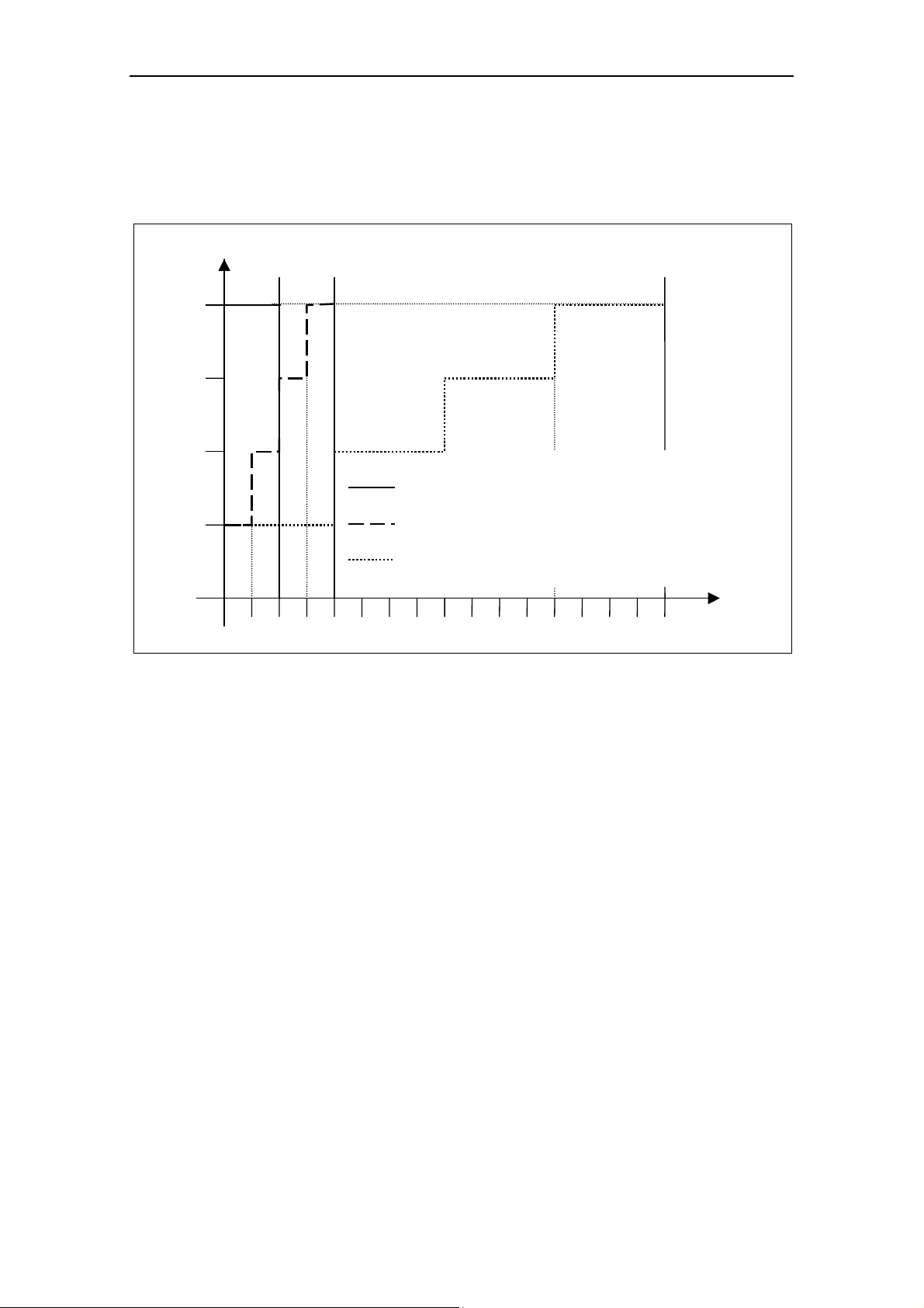
3.3.1 Ramp Times Using Jumpers
Inverter ramp times are set using a series of 5 jumpers (fit jumper to enable
function). Each jumper must be set as shown in Table 3-1.
The jumpers overwrite the default settings or the ramp times specified using
BOP/AOP/IBN software.
The inverter recognizes when jumper values have been set when power is reapplied.
CAUTION
Jumpers have priority in setting ramp times. When the jumpers are removed the
ramp times are not changed. It is then possible to change ramp times via the
parameters (using the BOP).
Ramp times apply to Ramp Up and Ramp Down. Jumper locations are as shown in
Figure 3-3.
Figure 3-3 Ramp Time Jumpers
Using up to 5 jumpers allows ramp times to be set between 1 - 240 s. Also see
Table 3-1.
Table 3-1 Ramp Time Adjustment Jumpers
Time [s] X20 X10 5 s 2 s 1 s Time [s] X20 X10 5 s 2 s 1 s
10
20
30
50
60
1
×
2
×
3
× ×
5
×
6
× ×
7
× ×
8
× × ×
× ×
× ×
× × ×
× ×
× × ×
70
80
90
100 ×
120 ×
140 ×
150
160 ×
180
210
240
× × ×
× × × ×
× ×
× × ×
× × ×
× × × ×
× × × × ×
× ×
×
×
× ×
× × ×
×
×
MICROMASTER 411 & COMBIMASTER 411 Operating Instructions
46
6SE6400-5CA00-0BP0
Page 47

Issue 03/01 3 Commissioning
Behaviour of the Ramp Time Jumpers
In Table 3-2 the behaviour of the Ramp Time Jumpers are explained:
Table 3-2 Ramp Time Jumper Behaviour
Status before action(s) Action(s) Reaction(s) of the inverter
No jumper fitted
Ramp times have arbitrary setting
At least one Jumper fitted
Ramp times have arbitrary setting
Power down
Fit jumper(s)
Power up
Power down
Power up
Inverter uses the ramp times defined by the current
jumper setting
Inverter uses the ramp times defined by the current
jumper setting
At least one Jumper fitted
Ramp times have arbitrary setting
Power down
Remove jumper(s)
Power up
NOTE
The brake time is influenced by the setting for the ramp time (deceleration time).
The following relationship applies:
Braking time = P1121 (deceleration time) *
3.3.2 Control Circuit Jumpers
Control Jumpers (see Table 3-3) are provided for the following functions (fit jumper
to enable function). Jumpers can only be accessed when the cover is removed:
Pot = Run
Enables the control potentiometer as the Command Source (auto restart is
enabled).
24 V AIN
To change analogue input range from 0 –10 V to 0 – 24 V
DC Brake
To change Stop function from OFF1 to DC Brake.
Inverter uses the ramp times that were used before
removing the jumper(s)
P0305 (nominal motor current)
r0207 (nominal inverter current)
Fan/Pump: M~n2
To change V/f curve from Linear to Quadratic curve.
60 Hz operation
To change motor default settings from 50 Hz to 60 Hz.
MICROMASTER 411 & COMBIMASTER 411 Operating Instructions
6SE6400-5CA00-0BP0
47
Page 48

3 Commissioning Issue 03/01
Figure 3-4 Control Circuit Jumpers
Table 3-3 Control Circuit Jumper Settings
Jumper Jumper Fitted Jumper Removed
Pot = Run P0700 = 2
24 AIN No software effect No software effect
DC Brake Uses the jumper settings for the ramp settings by the
Fan/Pump: M~n2 P1300 = 2 (fan curve/quadratic vf) P1300 = 0 (linear vf)
50/60 Hz Rated Motor Frequency = 60 Hz Rated Motor Frequency = 50 Hz
P0705 = 1 (motor potentiometer)
P1210 = 6 automatic restart
duration of the direct current braking, to be calculated as
follows.
Duration of direct current braking =
P1121 (deceleration time)
If the drive is quicker to come to a standstill because of the
load conditions, the direct current braking still remains
active fo the calculated time time.
Otherwise the value is held in P1233 (duration of the diret
current braking)
P0305 (nominal motor current)
*
r0207 (nominal inverter current)
P0700 = 2
P0701 = 1
P1210 = 1
P1233 = 0
Control Jumpers
In Table 3-4 the behaviour of the Control Jumpers are explained.
Table 3-4 Control Circuit Jumper Behaviour
Status before action(s) Action(s) Reaction(s) of the inverter
Jumper not fitted Power down
Fit jumper(s)
Power up
Jumper fitted Cycle power Parameters influenced by jumper are not changed
Jumper fitted Power down
Remove jumper
Power up
Jumper not fitted Cycle power Parameters influenced by jumper are not changed
MICROMASTER 411 & COMBIMASTER 411 Operating Instructions
48
Parameters influenced by jumper will have jumper default
values
Parameters influenced by jumper will have “jumper
removed“ default values (normally factory default)
6SE6400-5CA00-0BP0
Page 49

Issue 03/01 3 Commissioning
3.3.3 Default setup
To change parameters it is necessary to use a Basic Operator Panel (BOP),
Advanced Operator Panel (AOP) or an external serial interface with DriveMonitor
or STARTER. The inverter is therefore delivered with the following default settings:
Setpoint control from the Analog input in addition to Control Potentiometer.
Supply frequency set for 0 to 50 Hz.
Digital inputs:
DIN 1 ON/OFF1.
DIN 2 Reverse.
DIN 3 Fault Acknowledge
Jumpers for Ramp and Control circuits set to open (default settings). Refer to
sections 3.3.1 and 3.3.2.
Relay – Fault conditions.
3.3.4 Commissioning Overview with BOP or AOP
Prerequisites
Mechanical and electrical Installation is completed.
NOTE
We recommend the commissioning according this scheme.
Setting the motor frequency
Jumper 60Hz: OFF = 50 Hz / ON = 60 Hz
Power ON
Quick Commissioning P0010 = 1
See Section 3.3.4.3
Further Commissioning via P0004 and P0003
An overview of the parameter structure is given in
Section 5.3
For a detailed description of parameters, see the
Parameter List.
MICROMASTER 411 & COMBIMASTER 411 Operating Instructions
6SE6400-5CA00-0BP0
49
Page 50

3 Commissioning Issue 03/01
3.3.4.1 Commissioning with the Basic Operator Panel (BOP)
The Basic Operator Panel (BOP), which is available as an
optional accessory, provides the user with access to the
inverter parameters and enables you to customize the
settings of your COMBIMASTER 411 & MICROMASTER
411. The BOP is mounted in an Operator Panel Mounting
Kit and connected to the COMBIMASTER 411 &
MICROMASTER 411 via the serial interface (see Figure
3-9). The BOP can be used to configure several
COMBIMASTER 411 & MICROMASTER 411 Inverters.
The BOP features a five-digit, seven-segment display for
showing parameter numbers and values, alarm and fault messages and setpoints
and actual values. Parameter sets cannot be saved via the BOP.
Control functions for the inverter (ON/OFF,
, , reverse) are not active in the
works settings. In order to specify this command via the BOP, P0700 = 1 must be
set.
If the BOP connection is removed during normal running the drives is stopped and
the motor coasts to standstill.
Table 3-5 shows the factory default settings for operation via the BOP.
Table 3-5 Default Settings for BOP Operation
Parameter Meaning Default Europe (North America)
P0100 Operating Mode Europe/US 50 Hz, kW (60 Hz, hp)
P0307 Power (rated motor) kW (Hp)
P0310 Motor frequency rating 50 Hz (60 Hz)
P0311 Motor speed rating 1395 (1680) rpm [depending on variant]]
P1082 Maximum Motor Frequency 50 Hz (60 Hz)
MICROMASTER 411 & COMBIMASTER 411 Operating Instructions
50
6SE6400-5CA00-0BP0
Page 51

Issue 03/01 3 Commissioning
Buttons on the Basic Operator Panel
Panel/Button Function Effects
Indicates
Status
Start motor
The LCD displays the settings currently used by the inverter.
Pressing the button starts the inverter. This button is disabled by
default. To enable this button set P0700 = 1.
OFF1 Pressing the button causes the motor to come to a standstill
at the selected ramp down rate. Disabled by default; to
Stop motor
OFF2 Pressing the button twice (or once long) causes the motor to
enable set P0700 = 1.
coast to a standstill. This function is always enabled.
Change
direction
Press this button to change the direction of rotation of the motor.
Reverse is indicated by a minus (-) sign or a flashing decimal point.
Disabled by default, to enable set P0700 = 1.
Pressing this button while the inverter has no output causes the
Jog motor
motor to start and run at the preset jog frequency. The motor stops
when the button is released. Pressing this button when the motor is
running has no effect.
This button can be used to view additional information.
Pressing and holding the button for 2 seconds from any parameter
during operation, shows the following:
1. DC link voltage (indicated by d – units V).
2. Output current. (A)
3. Output frequency (Hz)
4. Output voltage (indicated by o – units V).
5. The value selected in P0005 (If P0005 is set to show any of the
Functions
above (1 to 4) then this will not be shown again).
Additional presses will toggle around the above displays.
Jump Function
From any parameter (rXXXX or PXXXX) a short press of the Fn
button will immediately jump to r0000, you can then change another
parameter, if required. Upon returning to r0000, pressing the Fn
button will return you to your starting point.
Quit
In case of a fault or alarm the
button resets the fault or alarm
message on the operator panel display.
Access
parameters
Increase
value
Decrease
value
Pressing this button allows access to the parameters.
Pressing this button increases the displayed value.
Pressing this button decreases the displayed value.
Figure 3-5 Basic Operator Panel Controls
MICROMASTER 411 & COMBIMASTER 411 Operating Instructions
6SE6400-5CA00-0BP0
51
Page 52

3 Commissioning Issue 03/01
Changing parameters with the BOP
The procedure for changing the value of parameter P0004 is described below.
Modifying the value of an indexed parameter is illustrated using the example of
P0719. Follow exactly the same procedure to alter other parameters that you wish
to set via the BOP.
Changing P0004 – parameter filter function
Step
1
Press to access parameters
2
Press until P0004 is displayed
3
Press to access the parameter value level
4
Press or
5
Press to confirm and store the value
Only the command parameters are visible to the user.
6
to the required value
Changing P0719 an indexed parameter
Selection of command/setpoint source
Result on display
Step
Result on display
1
Press to access parameters
2
Press until P0719 is displayed
3
Press to access the parameter value level
4
Press to display current set value
5
Press or
to the required value
6
Press to confirm and store the value
7
Press
Press to return the display to the standard drive display (as
8
defined by the customer)
until r0000 is displayed
Figure 3-6 Changing parameters via the BOP
NOTE
In some cases - when changing parameter values - the display on the BOP shows
. This means the inverter is busy with tasks of higher priority.
MICROMASTER 411 & COMBIMASTER 411 Operating Instructions
52
6SE6400-5CA00-0BP0
Page 53

Issue 03/01 3 Commissioning
Changing single digits in Parameter values
For changing the parameter value rapidly, the single digits of the display can be
changed by performing the following actions:
Ensure you are in the parameter value changing level (see "Changing parameters
with BOP").
1. Press
2. Change the value of this digit by pressing
3. Press
(function button), which causes the right hand digit to blink.
/ .
(function button) again causes the next digit to blink.
4. Perform steps 2 to 4 until the required value is displayed.
5. Press the
to leave the parameter value changing level.
NOTES
The function button may also be used to acknowledge a fault condition
3.3.4.2 Commissioning with the Advanced Operator Panel (AOP)
The Advanced Operator Panel (AOP) is available as an
option. Its advanced features include the following:
Multilingual clear text display
Upload/download facility for multiple parameter sets
Programmable via PC
Multidrop capability to drive up to 30 MICROMASTER
4’s
Please refer to the AOP Manual for details or contact your
local Siemens sales office for assistance.
3.3.4.3 Quick commissioning (P0010=1)
Mechanical and electrical installation of the inverter must be completed before
running „Quick Commissioning“.
It is important that the parameter P0010 is used for commissioning and P0003 for
selecting the parameter level (level). Quick commissioning particularly uses
parameters concerning the motor data and the acceleration and deceleration times.
Quick commissioning is ended with P3900. If this parameter is set to 1, it makes
the required motor calculations and sets all parameters which are not part of the
quick commissioning to the default values.
NOTE
Parameter P0399 = 0 must be set before starting quick commissioning because it
is not possible to change the motor data in the works default setting. Once quick
commissioning has been completed, P0399 = 2 must be set.
MICROMASTER 411 & COMBIMASTER 411 Operating Instructions
6SE6400-5CA00-0BP0
53
Page 54

3 Commissioning Issue 03/01
p
(A)
q
p
ge (V)
Flow chart Quick Commissioning (Level 1 Only)
P0010 Start Quick Commissioning
0 Ready to Run
1 Quick Commissioning
30 Factory Setting
Note
P0010 must always be set back to '0' before
operating the motor. However if P3900 = 1 is set
after commissioning this is done automatically.
P0100 Operation for Europe/N. America
0 Power in kW; f default 50 Hz
1 Power in hp; f default 60 Hz
2 Power in kW; f default 60 Hz
Note
Settings 0 & 1 can be changed using the 60Hz
Jum
er to allow permanent setting.
P0304 Rated Motor Voltage1)
10 V - 2000 V
Nominal motor volta
from rating plate
P0305 Rated Motor Current1)
0 - 2 x inverter rated current (A)
Nominal motor current
from rating plate
P0307 Rated Motor Power1)
0 kW - 2000 kW
Nominal motor power (kW) from rating plate.
If P0100 = 1, values will be in hp
P0310 Rated Motor Frequency1)
12 Hz - 650 Hz
Nominal motor fre
uency (Hz) from rating plate
P0311 Rated Motor Speed1)
0 - 40000 1/min
Nominal motor s
eed (rpm) from rating plate
1)
related parameters – please refer to motor rating plate drawing.
2)
Denotes parameters that contain more detailed lists of possible settings for use in specific
applications. Please refer to the Parameter List.
P0700 Selection of Command Source 2)
(on / off / reverse)
0 Factory Setting
1 Basic Operator Panel
2 Terminal / Digital Inputs (Default)
P1000 Selection of Frequency Setpoint 2)
0 No frequency setpoint
1. BOP frequency control ↑↓
2. Analogue Setpoint
27. Setpoint Addition: Analogue Setpoint &
Control Potentiometer(Default)
P1080 Min. Motor Frequency
Sets minimum motor frequency (0-650Hz) at which
the motor will run irrespective of the frequency
setpoint. The value set here is valid for both
clockwise and anti-clockwise rotation.
P1082 Max. Motor Frequency
Sets maximum motor frequency (0-650Hz) at which
the motor will run at irrespective of the frequency
setpoint. The value set here is valid for both
clockwise and anti-clockwise rotation.
P1120 Ramp-Up Time
0 s - 650 s
Time taken for the motor to accelerate from
standstill up to maximum motor frequency.
P1121 Ramp-Down Time
0 s - 650 s
Time taken for motor to decelerate from maximum
motor frequency down to standstill.
P3900 End Quick Commissioning
0 No Quick Commissioning.
1 Perform Quick Commissioning with factory reset
of all other Parameters (Recommended).
MICROMASTER 411 & COMBIMASTER 411 Operating Instructions
54
6SE6400-5CA00-0BP0
Page 55

Issue 03/01 3 Commissioning
Motor data for parameterization
Figure 3-7 Typical Motor Rating Plate Example
NOTICE
P0308 & P0309 are only visible if P0003 ≥ 2. Only one of the parameters is
shown depending on the settings of P0100.
Changing motor parameters is not possible unless P0010 = 1(factory setting)
and P0004 = 0 or 3.
Ensure that the inverter is configured correctly to the motor.
3.3.4.4 Reset to Factory default
To reset all parameters to the factory default settings; the following parameters
should be set as follows:
1. Set P0010 = 30
2. Set P0970 = 1
NOTICE
1. The reset process can take up to 3 minutes to complete.
2. Refer to Parameter P0399 for description on saving motor data sets while
performing a reset to the factory defaults.
MICROMASTER 411 & COMBIMASTER 411 Operating Instructions
6SE6400-5CA00-0BP0
55
Page 56

3 Commissioning Issue 03/01
3.4 General operation
For a full description of standard and extended parameters refer to the Parameter
List.
NOTICE
1. The inverter does not have a main power switch and is live when the power
supply is connected. It waits, with the output disabled, until the RUN button is
pressed or for the presence of a digital ON signal at terminal 1 (ON/OFF1).
2. If a BOP or an AOP is fitted and the output frequency is selected to be
displayed (P0005 = 21) the corresponding setpoint is displayed approximately
every 1.0 seconds while the inverter is stopped.
3. The inverter is programmed at the factory for standard applications on
Siemens four-pole standard motors that have the same power rating as the
inverters. When using other motors it is necessary to enter the specifications
from the motor's rating plate. See Figure 3-7 for details on how to read motor
data.
4. Changing motor parameters is not possible unless P0010 = 1 and P004 = 0
or 3.
5. You must set P0010 back to 0 in order to initiate a run.
3.4.1 Default Operation
For default operation, connect the terminals as shown in the figure below:
8 9
1 2 3 4 5 6 7
Figure 3-8 Default Setup Terminal Connections
FREQUENCY SETPOINT
Setpoint addition: Control potentiometer and Analog input (P1000 = 27).
MICROMASTER 411 & COMBIMASTER 411 Operating Instructions
56
6SE6400-5CA00-0BP0
Page 57

Issue 03/01 3 Commissioning
In order to provide the unit with a Frequency Setpoint the user can either:
1. Turn the control potentiometer.
2. Fit an external potentiometer, or apply an external analog control voltage across
the terminals 6 & 7 AIN.
NOTE
When using the analog input only, the control potentiometer should be turned fully
anti-clockwise to ensure that the control potentiometer is de-activated.
3.4.2 Operation using “Pot = Run” Jumper
With the “Pot = Run” jumper fitted, the control potentiometer provides the ON/OFF
command source.
In order to provide the unit with a Run command the Control Potentiometer must be
turned in a clockwise direction. To switch the unit OFF, turn the Control
Potentiometer fully anti-clockwise (OFF position).
WARNING
If the unit is powered up when the Control Potentiometer is not in the OFF
position, the unit may automatically restart and ramp-up to the frequency setpoint
(Auto-restart function is active by default).
FREQUENCY SETPOINT
Setpoint addition: Control potentiometer and Analog input (P1000 = 27).
In order to provide the unit with a Frequency Setpoint the user can either:
1. Turn the control potentiometer.
2. Fit an external potentiometer, or apply an external analog control voltage
across the terminals 6 and 7 AIN.
NOTES
The ‘Internal’ frequency setpoint set by the Control Potentiometer is ADDED
to the external frequency setpoint (set by either external potentiometer or
control voltage).
On mains break or fault, the inverter will automatically re-start on power-up
(Auto restart P1210 = 6 – default).
MICROMASTER 411 & COMBIMASTER 411 Operating Instructions
6SE6400-5CA00-0BP0
57
Page 58

3 Commissioning Issue 03/01
3.4.3 Non - Default Modes of Operation
Non-default modes of operation require the use of either a Keypad (BOP or AOP)
or a Commissioning tool (Drive Monitor or Starter) in order to change from the
default parameter settings.
The BOP, Part Number: 6SE6400-0BP00-0AA0 is housed in an Operator Panel
Mounting Kit, Part Number 6SE6401-1DF00-0AA0 and connected via the Interface
Link Cable, Part Number 6SE6401-1BL00-0AA0 to the Inverter serial comms port.
This arrangement is shown in Figure 3-9.
Figure 3-9 Connect BOP/AOP with the MICROMASTER 411
Prerequisites
P0010 = 0 (in order to initiate the run command correctly).
P0700 = 1 (enables the start/stop button on the BOP).
P1000 = 1 (this enables the motor potentiometer setpoints).
1. Press the green Button
2. Press the Button
to start the motor.
while the motor is turning. Motor speed increases to
50 Hz.
3. When the inverter reaches 50 Hz, press the Button
. Motor speed and
display is decreased.
4. Change the direction of rotation with the
5. The red button stops the motor
MICROMASTER 411 & COMBIMASTER 411 Operating Instructions
58
Button .
.
6SE6400-5CA00-0BP0
Page 59

Issue 03/01 3 Commissioning
Stopping the Motor
When the inverter is being operated using the Run/Stop switch (connected to
DIN1) setting the switch to OFF will override the potentiometer setting and bring
the motor to a controlled stop.
3.4.4 If the Motor does not start up
Refer to Chapter 6.
3.4.5 If a fault occurs
1. Switch the Inverter off.
2. Disconnect and reconnect the power supply.
3. Switch on again.
4. Faults are acknowledged by using digital input DIN 3 (default setting).
Switch off if the fault condition persists.
MICROMASTER 411 & COMBIMASTER 411 Operating Instructions
6SE6400-5CA00-0BP0
59
Page 60

3 Commissioning Issue 03/01
MICROMASTER 411 & COMBIMASTER 411 Operating Instructions
60
6SE6400-5CA00-0BP0
Page 61

Issue 03/01 4 Using the MICROMASTER 411 / COMBIMASTER 411
4 Using the MICROMASTER 411 /
COMBIMASTER 411
This Chapter contains:
An explanation of the various methods of controlling the inverter
A summary of the types of control of the inverter
4.1
4.2
4.3
4.4
4.5
Frequency Setpoint ................................................................................................. 62
Command Sources (P0700).................................................................................... 63
OFF and Braking Functions .................................................................................... 63
Control Modes (P1300) ........................................................................................... 65
Faults and warnings ................................................................................................ 65
MICROMASTER 411 & COMBIMASTER 411 Operating Instructions
6SE6400-5CA00-0BP0
61
Page 62

4 Using the MICROMASTER 411 / COMBIMASTER 411 Issue 03/01
WARNING
When operating electrical devices, it is impossible to avoid applying hazardous
voltages to certain parts of the equipment.
Emergency Stop facilities according to EN 60204 IEC 204 (VDE 0113) must
remain functional in all operating modes of the control equipment. Any
disengagement of the Emergency Stop facility must not lead to uncontrolled or
undefined restarts.
Faults occurring in the control equipment can lead to substantial material
damage, or even grievous bodily injury (i.e. potentially dangerous faults).
Additional external precautions must be taken, or facilities provided, to ensure
safe operation, (e.g. independent limit switches, mechanical interlocks, etc.).
COMBIMASTER 411/MICROMASTER 411 operate at high voltages.
Certain parameter settings may cause the inverter to restart automatically after
an input power failure.
This equipment is capable of providing internal motor overload protection.
Refer to P0610 (level 3) and P0335. I
2
t is ON by default. Motor overload
protection can also be provided using an external PTC via a digital input.
This equipment is suitable for use in a circuit capable of delivering not more
than 10,000 symmetrical amperes (rms), for a maximum voltage of 460 V
when protected by a H or K Class fuse (see Table 7-6).
This equipment must not be used as an ‘Emergency Stop mechanism’ (see
EN 60204, 9.2.5.4)
4.1 Frequency Setpoint
Default: Setpoint Addition: Terminal 6/7 (AIN+/ AIN -)/Control Potentiometer
Options see P1000
NOTE
For frequency setpoint via PROFIBUS see PROFIBUS Instructions.
MICROMASTER 411 & COMBIMASTER 411 Operating Instructions
62
6SE6400-5CA00-0BP0
Page 63

Issue 03/01 4 Using the MICROMASTER 411 / COMBIMASTER 411
4.2 Command Sources (P0700)
NOTICE
The ramp times and ramp-smoothing functions also affect how the motor starts
and stops. For details of these functions, please refer to parameters P1120, P1121,
P1130 – P1134 in the Parameter List.
Starting the motor
Default Terminal 1 (DIN 1): (P0700=2)
Other Settings see P0700 to P0704
Stopping the motor
There are several ways to stop the motor:
Default:
♦ OFF1 (4.3.1) Terminal 1 (DIN 1): (P0700=2)
♦ OFF2 (4.3.2) Off button on BOP/AOP. Pressing the Off button once
(two seconds) or twice (with default settings). This is not
possible without BOP/AOP
♦ OFF3 (4.3.3) no standard setting
Other Settings see P0700 to P0704
Reversing the motor
Default Terminal 2 (DIN 2)
Other Settings see P0700 to P0704
4.3 OFF and Braking Functions
4.3.1 OFF1
This command (produced by canceling the ON command) causes the inverter to
come to a standstill at the selected ramp-down rate.
Parameter to change ramp time see P1121
NOTICE
ON and the following OFF1 command must have the same source.
If the ON/OFF1 Command is set to more than one Digital input, only the last
set Digital Input is active e.g. DIN3 active.
OFF1 can be combined with DC braking or Compound braking.
MICROMASTER 411 & COMBIMASTER 411 Operating Instructions
6SE6400-5CA00-0BP0
63
Page 64

4 Using the MICROMASTER 411 / COMBIMASTER 411 Issue 03/01
4.3.2 OFF2
This command causes the motor to coast to a standstill.
NOTICE
The OFF2 command can have one or more sources. By default the OFF2
command is set to BOP/AOP. This source still exists even if other sources are
defined by one of the following parameters, P0700, P0701, P0702, P0703 and
P0704.
4.3.3 OFF3
An OFF3 command causes the motor to decelerate rapidly.
For starting the motor when OFF3 is set, the binary input has to be closed (high). If
OFF3 is high, the motor can be started and stopped by ON/OFF1 or ON/OFF2.
Ist AUS3 geöffnet, ist ein Starten des Motors nicht möglich.
Ramp down time: see P1135
NOTICE
OFF3 can be combined with DC braking or compound braking
4.3.4 DC braking
DC braking is possible together with OFF1 and OFF3. A DC current is applied to
stop the motor quickly.
set DC braking: see P0701 to P0704
set braking period: see P1233
set braking current: see P1232
NOTICE
If no digital input is set to DC braking and P1233 ≠ 0, DC braking will be active after
every OFF1 command.
4.3.5 Compound Braking
Compound Braking is possible with both OFF1 and OFF3. For Compound Braking
a DC component is added to the AC current.
Set the braking current: see P1236
MICROMASTER 411 & COMBIMASTER 411 Operating Instructions
64
6SE6400-5CA00-0BP0
Page 65

Issue 03/01 4 Using the MICROMASTER 411 / COMBIMASTER 411
4.4 Control Modes (P1300)
The various modes of operation of the MICROMASTER 411 control the relationship between the speed of the motor and the voltage supplied by the inverter. A
summary of the control modes available are listed below:
Linear V/f control P1300 = 0
Can be used for variable and constant torque applications, such as conveyors
and positive displacement pumps.
Linear V/f control with FCC (Flux Current Control) P1300 = 1
This control mode can be used to improve the efficiency and dynamic
response of the motor.
Quadratic V/f control P1300 = 2
This mode can be used for variable torque loads, such as fans and pumps.
Multi-point V/f control P1300 = 3
Multi-point V/f allows the user to define their own V/f Characteristics.
This characteristic uses two fixed coordinates and three pairs of variable
coordinates.
Fixed co-ordinates are: Boost as defined in P1310 at 0 Hz.
Nominal voltage P0304 at nominal frequency P0310
Variable co-ordinates may be obtained from the following three pairs of
coordinates
P1320 (frequency) -P1321 (voltage)
P1322 (frequency) -P1323 (voltage)
P1324 (frequency) -P1325 (voltage)
User programmable V/f characteristics are often used to provide correct torque
at correct frequency, which can be useful when using the Inverter with
synchronous motors. See Parameter List for further detail.
4.5 Faults and warnings
LED Fault Indication
Fault states and warnings are indicated by the LED within the control potentiometer
on the inverter, see section 6.1 for further information.
BOP fitted
If a BOP is fitted, the fault states (P0947) and warnings (P2110) are displayed
should a fault condition occur. For further details, please refer to section 6.2.
AOP fitted
If the AOP is fitted, fault and warning codes are displayed on the LCD panel.
MICROMASTER 411 & COMBIMASTER 411 Operating Instructions
6SE6400-5CA00-0BP0
65
Page 66

4 Using the MICROMASTER 411 / COMBIMASTER 411 Issue 03/01
MICROMASTER 411 & COMBIMASTER 411 Operating Instructions
66
6SE6400-5CA00-0BP0
Page 67

Issue 03/01 5 System Parameters
5 System Parameters
This Chapter contains:
An overview of the parameter structure of the MICROMASTER 411 /
COMBIMASTER 411
A parameter list in short form
5.1
5.2
5.3
Introduction to System Parameters.........................................................................68
Parameter Structure................................................................................................ 69
Parameter List (short form) ..................................................................................... 70
MICROMASTER 411 & COMBIMASTER 411 Operating Instructions
6SE6400-5CA00-0BP0
67
Page 68

5 System Parameters Issue 03/01
5.1 Introduction to System Parameters
Parameters can only be changed by using the Basic Operator Panel (BOP),
the Advanced Operator Panel (AOP) or Serial Interface.
NOTE
Full details of the COMBIMASTER 411 /MICROMASTER 411 Parameters can
be found in the separate document “COMBIMASTER 411/MICROMASTER
411 – Parameter List”.
This document is included in the CD ROM delivered with the product.
Parameters may be changed and set (using the BOP) to adjust the desired
properties of the inverter, such as ramp times, minimum and maximum frequencies
etc. The parameter numbers selected and the setting of the parameter values are
indicated on the optional five-digit LCD display.
rxxxx indicates a display parameter, Pxxxx a setting parameter.
P0010 initiates “Quick Commissioning”. Set P0010 to 1.
The inverter will not run unless P0010 is set to 0 after it has been accessed.
This function is automatically performed if P3900 > 0.
P0004 acts as a filter, allowing access to parameters according to their
functionality group.
If an attempt is made to change a parameter that cannot be changed in this
status, for example, cannot be changed whilst running or can only be changed
in quick commissioning, then
Busy Message
In some cases - when changing parameter values - the display on the BOP
will be displayed.
shows
busy with tasks of higher priority.
for maximum of five seconds. This means the inverter is
5.1.1 Access Levels
There are three access levels available to the user; Standard, Extended and
Expert. The level of access is set by parameter P0003. For most applications, the
Standard and Extended levels are sufficient.
The number of parameters that appear within each functional group depends on
the access level set in parameter P0003. For further details regarding parameters,
see the Parameter List on the Documentation CD-ROM.
MICROMASTER 411 & COMBIMASTER 411 Operating Instructions
68
6SE6400-5CA00-0BP0
Page 69

Issue 03/01 5 System Parameters
5.2 Parameter Structure
P0004 = 2
Inverter Unit
P0004 = 2, P0003 = 1
Parameters level 1
concerning the inverter unit
P0004 = 2, P0003 = 2
P0004 = 0
(no filter function)
allows direct access
to the parameters.
For BOP and AOP
depending on the
selected access level
P0004 = 2, P0003 = 3
Parameters level 1, 2 and 3
concerning the inverter unit
Parameters level 1 and 2
concerning the inverter unit
P0004 = 2, P0003 = 4
Parameters level 1, 2, 3 and 4
concerning the inverter unit
P0004 = 21
Alarms, Warnings &
Monitoring
P0004 = 20
Communication
P0004 = 13
Motor Control
P0004 = 12
Drive Features
P0004 = 22
PI Controller
3
0
0
0
0
0
0
3
P
P
0
P
P0004 = 10
Setpoint Channel &
Ramp Generator
=
0
=
0
P0004 = 2
Inverter Unit
n
n
d
d
e
a
d
P0004 = 3
Motor Data
r
d
P0004 = 7
Commands and
Digital I/O
v
e
v
e
e
L
,
e
L
,
4
e
l
S
t
a
e
l
E
x
t
e
v
e
l
E
x
p
v
e
P0004 = 8
Analogue I/O
e
l
r
t
S
e
r
v
i
c
e
L
,
1
L
,
2
3
=
3
=
3
0
0
0
P
Figure 5-1 Parameter Structure with Filter (P0004)
MICROMASTER 411 & COMBIMASTER 411 Operating Instructions
6SE6400-5CA00-0BP0
69
Page 70

5 System Parameters Issue 03/01
5.3 Parameter List (short form)
Explanatory information on following table:
Default: Factory setting
Level: Access level
DS Inverter status (Drive State), indicates the inverter state in which a
parameter can be modified (see P0010).
♦ C Commissioning
♦ U Run
♦ T Ready to run
QC Quick Commissioning
♦ Q Parameter can be modified in the Quick Commissioning state.
♦ N Parameter cannot be modified in the Quick Commissioning state.
Always
ParNr ParText Default Acc WS QC
r0000 Drive display - 1 - -
P0003 User access level 1 1 CUT N
P0004 Parameter filter 0 1 CUT N
P0010 Commissioning parameter 0 1 CT N
P0014[3] Store mode 0 3 UT N
P0199 Equipment system number 0 2 UT N
Quick Commissioning
ParNr ParText Default Acc WS QC
P0100 Europe / North America 0 1 C Q
P3900 End of quick commissioning 0 1 C Q
Parameter reset
ParNr ParText Default Acc WS QC
P0970 Factory reset 0 1 C N
Inverter Unit (P0004 = 2)
ParNr ParText Default Acc WS QC
r0018 Firmware version - 1 - -
r0026[1] CO: Act. filtered DC-link volt. - 2 - -
r0037[1] CO: Inverter temperature [°C] - 3 - -
r0039 CO: Energy consumpt. meter [kWh] - 2 - -
P0040 Reset energy consumption meter 0 2 CT N
r0200 Act. power stack code number - 3 - -
P0201 Power stack code number 0 3 C N
r0203 Act. inverter type - 3 - -
r0204 Power stack features - 3 - -
r0206 Rated inverter power [kW] / [hp] - 2 - -
r0207 Rated inverter current - 2 - -
MICROMASTER 411 & COMBIMASTER 411 Operating Instructions
70
6SE6400-5CA00-0BP0
Page 71

Issue 03/01 5 System Parameters
ParNr ParText Default Acc WS QC
r0208 Rated inverter voltage - 2 - -
r0209 Maximum inverter current - 2 - -
P0210 Supply voltage 230 3 CT N
P0290 Inverter overload reaction 2 3 CT N
P0292 Inverter overload warning 5 3 CUT N
P1800 Pulse frequency 4 2 CUT N
r1801 CO: Act. pulse frequency - 3 - -
P1802 Modulator mode 0 3 CUT N
P1820[1] Reverse output phase sequence 0 2 CT N
Motor data (P0004 = 3)
ParNr ParText Default Acc WS QC
r0034[1] CO: Motor temperature (i2t) - 2 - -
P0300[1] Select motor type 1 2 C Q
P0304[1] Rated motor voltage 230 1 C Q
P0305[1] Rated motor current 3.25 1 C Q
P0307[1] Rated motor power 0.75 1 C Q
P0308[1] Rated motor cosPhi 0.000 2 C Q
P0309[1] Rated motor efficiency 0.0 2 C Q
P0310[1] Rated motor frequency 50.00 1 C Q
P0311[1] Rated motor speed 0 1 C Q
r0313[1] Motor pole pairs - 3 - -
P0320[1] Motor magnetizing current 0.0 3 CT Q
r0330[1] Rated motor slip - 3 - -
r0331[1] Rated magnetization current - 3 - -
r0332[1] Rated power factor - 3 - -
P0335[1] Motor cooling 0 2 CT Q
P0340[1] Calculation of motor parameters 0 2 CT N
P0344[1] Motor weight 9.4 3 CUT N
P0346[1] Magnetization time 1.000 3 CUT N
P0347[1] Demagnetization time 1.000 3 CUT N
P0350[1] Stator resistance (line-to-line) 4.00000 2 CUT N
r0384[1] Rotor time constant - 3 - -
r0395 CO: Total stator resistance [%] - 3 - -
P0399 Motor mirror mode 2 3 CT N
P0610[1] Motor I2t temperature reaction 2 3 CT N
P0611[1] Motor I2t time constant 100 2 CT N
P0614[1] Motor I2t overload warning level 100.0 2 CUT N
P0640[1] Motor overload factor [%] 150.0 2 CUT Q
P1910 Select motor data identification 0 2 CT Q
r1912[1] Identified stator resistance - 2 - -
MICROMASTER 411 & COMBIMASTER 411 Operating Instructions
6SE6400-5CA00-0BP0
71
Page 72

5 System Parameters Issue 03/01
Command and Digital I/O (P0004 = 7)
ParNr ParText Default Acc WS QC
r0002 Drive state - 2 - -
r0019 CO/BO: BOP control word - 3 - -
r0052 CO/BO: Act. status word 1 - 2 - -
r0053 CO/BO: Act. status word 2 - 2 - -
r0054 CO/BO: Act. control word 1 - 3 - -
r0055 CO/BO: Act. control word 2 - 3 - -
P0700[1] Selection of command source 2 1 CT Q
P0701[1] Function of digital input 1 1 2 CT N
P0702[1] Function of digital input 2 12 2 CT N
P0703[1] Function of digital input 3 9 2 CT N
P0704[1] Function of digital input 4 0 2 CT N
P0705[1] Function of digital input 5 0 2 CT N
r0720 Number of digital inputs - 3 - -
P0719[2] Selection of cmd. & freq. setp. 0 3 CT N
r0722 CO/BO: Binary input values - 2 - -
P0724 Debounce time for digital inputs 3 3 CT N
r0730 Number of digital outputs - 3 - -
P0731[1] BI: Function of digital output 1 52:3 2 CUT N
r0747 CO/BO: State of digital outputs - 3 - -
P0748 Invert digital outputs 0 3 CUT N
P0800[1] BI: Download parameter set 0 0:0 3 CT N
P0801[1] BI: Download parameter set 1 0:0 3 CT N
P0810 BI: CDS bit 0 (Local / Remote) 0:0 2 CUT N
P0840[1] BI: ON/OFF1 722:0 3 CT N
P0842[1] BI: ON reverse/OFF1 0:0 3 CT N
P0844[1] BI: 1. OFF2 1:0 3 CT N
P0845[1] BI: 2. OFF2 19:1 3 CT N
P0848[1] BI: 1. OFF3 1:0 3 CT N
P0849[1] BI: 2. OFF3 1:0 3 CT N
P0852[1] BI: Pulse enable 1:0 3 CT N
P1020[1] BI: Fixed freq. selection Bit 0 0:0 3 CT N
P1021[1] BI: Fixed freq. selection Bit 1 0:0 3 CT N
P1022[1] BI: Fixed freq. selection Bit 2 0:0 3 CT N
P1035[1] BI: Enable MOP (UP-command) 19:13 3 CT N
P1036[1] BI: Enable MOP (DOWN-command) 19:14 3 CT N
P1055[1] BI: Enable JOG right 0:0 3 CT N
P1056[1] BI: Enable JOG left 0:0 3 CT N
P1074[1] BI: Disable additional setpoint 0:0 3 CUT N
P1110[1] BI: Inhibit neg. freq. setpoint 0:0 3 CT N
P1113[1] BI: Reverse 722:1 3 CT N
P1124[1] BI: Enable JOG ramp times 0:0 3 CT N
P1140[1] BI: RFG enable 1:0 3 CT N
P1141[1] BI: RFG start 1:0 3 CT N
MICROMASTER 411 & COMBIMASTER 411 Operating Instructions
72
6SE6400-5CA00-0BP0
Page 73

Issue 03/01 5 System Parameters
ParNr ParText Default Acc WS QC
P1142[1] BI: RFG enable setpoint 1:0 3 CT N
P1230[1] BI: Enable DC braking 0:0 3 CUT N
P2103[1] BI: 1. Faults acknowledgement 722:2 3 CT N
P2104[1] BI: 2. Faults acknowledgement 0:0 3 CT N
P2106[1] BI: External fault 1:0 3 CT N
P2220[1] BI: Fixed PID setp. select Bit 0 0:0 3 CT N
P2221[1] BI: Fixed PID setp. select Bit 1 0:0 3 CT N
P2222[1] BI: Fixed PID setp. select Bit 2 0:0 3 CT N
P2235[1] BI: Enable PID-MOP (UP-cmd) 19:13 3 CT N
P2236[1] BI: Enable PID-MOP (DOWN-cmd) 19:14 3 CT N
Analogue I/O (P0004 = 8)
r0750 Number of ADCs - 3 - -
r0752[2] Act. input of ADC [V] - 2 - -
P0753[1] Smooth time ADC 3 3 CUT N
r0754[2] Act. ADC value after scaling [%] - 2 - -
r0755[2] CO: Act. ADC after scal. [4000h] - 2 - -
P0756[1] Type of ADC 0 2 CT N
P0757[1] Value x1 of ADC scaling [V] 0 2 CUT N
P0758[1] Value y1 of ADC scaling 0.0 2 CUT N
P0759[1] Value x2 of ADC scaling [V] 10 2 CUT N
P0760[1] Value y2 of ADC scaling 100.0 2 CUT N
P0761[1] Width of ADC deadband [V] 0 2 CUT N
P0762[1] Delay for loss of signal action 10 3 CUT N
Setpoint Channel and Ramp Generator (P0004 = 10)
ParNr ParText Default Acc WS QC
P1000[1] Selection of frequency setpoint 27 1 CT Q
P1001[1] Fixed frequency 1 0.00 2 CUT N
P1002[1] Fixed frequency 2 5.00 2 CUT N
P1003[1] Fixed frequency 3 10.00 2 CUT N
P1004[1] Fixed frequency 4 15.00 2 CUT N
P1005[1] Fixed frequency 5 20.00 2 CUT N
P1006[1] Fixed frequency 6 25.00 2 CUT N
P1007[1] Fixed frequency 7 30.00 2 CUT N
P1016 Fixed frequency mode – Bit 0 1 3 CT N
P1017 Fixed frequency mode – Bit 1 1 3 CT N
P1018 Fixed frequency mode – Bit 2 1 3 CT N
r1024 CO: Act. fixed frequency - 3 - -
P1031[1] Setpoint memory of the MOP 0 2 CUT N
P1032 Inhibit reverse direction of MOP 1 2 CT N
P1040[1] Setpoint of the MOP 5.00 2 CUT N
r1050 CO: Act. Output freq. of the MOP - 3 - -
P1058[1] JOG frequency right 5.00 2 CUT N
P1059[1] JOG frequency left 5.00 2 CUT N
MICROMASTER 411 & COMBIMASTER 411 Operating Instructions
6SE6400-5CA00-0BP0
73
Page 74

5 System Parameters Issue 03/01
ParNr ParText Default Acc WS QC
P1060[1] JOG ramp-up time 10.00 2 CUT N
P1061[1] JOG ramp-down time 10.00 2 CUT N
P1070[1] CI: Main setpoint 755:0 3 CT N
P1071[1] CI: Main setpoint scaling 1:0 3 CT N
P1075[1] CI: Additional setpoint 755:1 3 CT N
P1076[1] CI: Additional setpoint scaling 1:0 3 CT N
r1078 CO: Total frequency setpoint - 3 - -
r1079 CO: Selected frequency setpoint - 3 - -
P1080[1] Min. frequency 0.00 1 CUT Q
P1082[1] Max. frequency 50.00 1 CT Q
P1091[1] Skip frequency 1 0.00 3 CUT N
P1092[1] Skip frequency 2 0.00 3 CUT N
P1093[1] Skip frequency 3 0.00 3 CUT N
P1094[1] Skip frequency 4 0.00 3 CUT N
P1101[1] Skip frequency bandwidth 2.00 3 CUT N
r1114 CO: Freq. setp. after dir. ctrl. - 3 - -
r1119 CO: Freq. setpoint before RFG - 3 - -
P1120[1] Ramp-up time 10.00 1 CUT Q
P1121[1] Ramp-down time 10.00 1 CUT Q
P1130[1] Ramp-up initial rounding time 0.00 2 CUT N
P1131[1] Ramp-up final rounding time 0.00 2 CUT N
P1132[1] Ramp-down initial rounding time 0.00 2 CUT N
P1133[1] Ramp-down final rounding time 0.00 2 CUT N
P1134[1] Rounding type 0 2 CUT N
P1135[1] OFF3 ramp-down time 5.00 2 CUT Q
r1170 CO: Frequency setpoint after RFG - 3 - -
Drive Features (P0004 = 12)
ParNr ParText Default Acc WS QC
P0005[1] Display selection 21 2 CUT N
P0006 Display mode 2 3 CUT N
P0007 Backlight delay time 0 3 CUT N
P0011 Lock for user defined parameter 0 3 CUT N
P0012 Key for user defined parameter 0 3 CUT N
P0013[20] User defined parameter 0 3 CUT N
P1200 Flying start 0 2 CUT N
P1202[1] Motor-current: Flying start 100 3 CUT N
P1203[1] Search rate: Flying start 100 3 CUT N
P1210 Automatic restart 1 2 CUT N
P1211 Number of restart attempts 3 3 CUT N
P1215 Holding brake enable 0 2 T N
P1216 Holding brake release delay 1.0 2 T N
P1217 Holding time after ramp down 1.0 2 T N
P1232[1] DC braking current 100 2 CUT N
P1233[1] Duration of DC braking 0 2 CUT N
MICROMASTER 411 & COMBIMASTER 411 Operating Instructions
74
6SE6400-5CA00-0BP0
Page 75

Issue 03/01 5 System Parameters
ParNr ParText Default Acc WS QC
P1236[1] Compound braking current 0 2 CUT N
P1240[1] Configuration of Vdc controller 1 3 CT N
r1242 CO: Switch-on level of Vdc-max - 3 - -
P1243[1] Dynamic factor of Vdc-max 100 3 CUT N
P1253[1] Vdc-controller output limitation 10.00 3 CUT N
P1254 Auto detect Vdc switch-on levels 1 3 CT N
Motor Control (P0004 = 13)
ParNr ParText Default Acc WS QC
r0020 CO: Freq. setpoint before RFG - 3 - -
r0021 CO: Act. frequency - 2 - -
r0022 Act. filtered rotor speed - 3 - -
r0024 CO: Act. output frequency - 3 - -
r0025 CO: Act. output voltage - 2 - -
r0027 CO: Act. output current - 2 - -
r0056 CO/BO: Status of motor control - 3 - -
r0057 Jumper status - 2 - -
r0067 CO: Act. output current limit - 3 - -
r0071 CO: Max. output voltage - 3 - -
r0078 CO: Act. current Isq - 3 - -
r0086 CO: Act. active current - 3 - -
P1300[1] Control mode 0 2 CT Q
P1310[1] Continuous boost 50.0 2 CUT N
P1311[1] Acceleration boost 0.0 2 CUT N
P1312[1] Starting boost 0.0 2 CUT N
P1316[1] Boost end frequency 20.0 3 CUT N
P1320[1] Programmable V/f freq. coord. 1 0.00 3 CT N
P1321[1] Programmable V/f volt. coord. 1 0.0 3 CUT N
P1322[1] Programmable V/f freq. coord. 2 0.00 3 CT N
P1323[1] Programmable V/f volt. coord. 2 0.0 3 CUT N
P1324[1] Programmable V/f freq. coord. 3 0.00 3 CT N
P1325[1] Programmable V/f volt. coord. 3 0.0 3 CUT N
P1333[1] Start frequency for FCC 10.0 3 CUT N
P1335[1] Slip compensation 0.0 2 CUT N
P1336[1] Slip limit 250 2 CUT N
r1337 CO: V/f slip frequency - 3 - -
P1338[1] Resonance damping gain V/f 0.00 3 CUT N
P1340[1] Imax controller prop. gain 0.000 3 CUT N
P1341[1] Imax controller integral time 0.300 3 CUT N
r1343 CO: Imax controller freq. output - 3 - -
r1344 CO: Imax controller volt. output - 3 - -
P1350[1] Voltage soft start 0 3 CUT N
MICROMASTER 411 & COMBIMASTER 411 Operating Instructions
6SE6400-5CA00-0BP0
75
Page 76

5 System Parameters Issue 03/01
Communication (P0004 = 20)
ParNr ParText Default Acc WS QC
P0918 CB address 3 2 CT N
P0927 Parameter changeable via 15 2 CUT N
r0965 Profibus profile - 3 - -
r0967 Control word 1 - 3 - -
r0968 Status word 1 - 3 - -
r0964[5] Firmware version data - 3 - -
P0971 Transfer data from RAM to EEPROM 0 3 CUT N
P2000[1] Reference frequency 50.00 2 CT N
P2001[1] Reference voltage 1000 3 CT N
P2002[1] Reference current 0.10 3 CT N
P2009[2] USS normalization 0 3 CT N
P2010[2] USS baudrate 6 2 CUT N
P2011[2] USS address 0 2 CUT N
P2012[2] USS PZD length 2 3 CUT N
P2013[2] USS PKW length 127 3 CUT N
P2014[2] USS telegram off time 0 3 CT N
r2015[4] CO: PZD from BOP link (USS) - 3 - -
P2016[4] CI: PZD to BOP link (USS) 52:0 3 CT N
r2018[4] CO: PZD from COM link (USS) - 3 - -
P2019[4] CI: PZD to COM link (USS) 52:0 3 CT N
r2024[2] USS error-free telegrams - 3 - -
r2025[2] USS rejected telegrams - 3 - -
r2026[2] USS character frame error - 3 - -
r2027[2] USS overrun error - 3 - -
r2028[2] USS parity error - 3 - -
r2029[2] USS start not identified - 3 - -
r2030[2] USS BCC error - 3 - -
r2032 BO: CtrlWrd1 from BOP link (USS) - 3 - -
r2031[2] USS length error - 3 - -
r2033 BO: CtrlWrd2 from BOP link (USS) - 3 - -
r2036 BO: CtrlWrd1 from COM link (USS) - 3 - -
r2037 BO: CtrlWrd2 from COM link (USS) - 3 - -
P2040 CB telegram off time 20 3 CT N
P2041[5] CB parameter 0 3 CT N
r2050[4] CO: PZD from CB - 3 - -
P2051[4] CI: PZD to CB 52:0 3 CT N
r2053[5] CB identification - 3 - -
r2054[7] CB diagnosis - 3 - -
r2090 BO: Control word 1 from CB - 3 - -
r2091 BO: Control word 2 from CB - 3 - -
MICROMASTER 411 & COMBIMASTER 411 Operating Instructions
76
6SE6400-5CA00-0BP0
Page 77

Issue 03/01 5 System Parameters
Alarms and Warnings (P0004 = 21)
ParNr ParText Default Acc WS QC
P0952 Total number of faults 0 3 CT N
r0947[8] Last fault code - 2 - -
r0949[8] Fault value - 3 - -
r0948[12] Fault time - 3 - -
P2100[3] Alarm number selection 0 3 CT N
P2101[3] Stop reaction value 0 3 CT N
P2111 Total number of warnings 0 3 CT N
r2110[4] Warning number - 2 - -
r2114[2] Run time counter - 3 - -
P2150[1] Hysteresis frequency f_hys 3.00 3 CUT N
P2155[1] Threshold frequency f_1 30.00 3 CUT N
P2156[1] Delay time of threshold freq f_1 10 3 CUT N
P2164[1] Hysteresis frequency deviation 3.00 3 CUT N
P2167[1] Switch-off frequency f_off 1.00 3 CUT N
P2168[1] Delay time T_off 10 3 CUT N
P2170[1] Threshold current I_thresh 100.0 3 CUT N
P2171[1] Delay time current 10 3 CUT N
P2172[1] Threshold DC-link voltage 800 3 CUT N
P2173[1] Delay time DC-link voltage 10 3 CUT N
P2179 Current limit for no load ident. 3.0 3 CUT N
P2180 Delay time for load missing 2000 3 CUT N
r2197 CO/BO: Monitoring word 1 - 2 - -
PI Controller (P0004=22)
ParNr ParText Default Acc WS QC
P2200[1] BI: Enable PID controller 0:0 2 CUT N
P2201[1] Fixed PID setpoint 1 0.00 2 CUT N
P2202[1] Fixed PID setpoint 2 10.00 2 CUT N
P2203[1] Fixed PID setpoint 3 20.00 2 CUT N
P2204[1] Fixed PID setpoint 4 30.00 2 CUT N
P2205[1] Fixed PID setpoint 5 40.00 2 CUT N
P2206[1] Fixed PID setpoint 6 50.00 2 CUT N
P2207[1] Fixed PID setpoint 7 60.00 2 CUT N
P2216 Fixed PID setpoint mode - Bit 0 1 3 CT N
P2217 Fixed PID setpoint mode - Bit 1 1 3 CT N
P2218 Fixed PID setpoint mode - Bit 2 1 3 CT N
r2224 CO: Act. fixed PID setpoint - 2 - -
P2231[1] Setpoint memory of PID-MOP 0 2 CUT N
P2232 Inhibit rev. direct. of PID-MOP 1 2 CT N
P2240[1] Setpoint of PID-MOP 10.00 2 CUT N
r2250 CO: Output setpoint of PID-MOP - 2 - -
P2253[1] CI: PID setpoint 0:0 2 CUT N
P2254[1] CI: PID trim source 0:0 3 CUT N
MICROMASTER 411 & COMBIMASTER 411 Operating Instructions
6SE6400-5CA00-0BP0
77
Page 78

5 System Parameters Issue 03/01
ParNr ParText Default Acc WS QC
P2255 PID setpoint gain factor 100.00 3 CUT N
P2256 PID trim gain factor 100.00 3 CUT N
P2257 Ramp-up time for PID setpoint 1.00 2 CUT N
P2258 Ramp-down time for PID setpoint 1.00 2 CUT N
r2260 CO: PID setpoint after PID-RFG - 2 - -
P2261 PID setpoint filter timeconstant 0.00 3 CUT N
r2262 CO: Filtered PID setp. after RFG - 3 - -
P2264[1] CI: PID feedback 755:0 2 CUT N
P2265 PID feedback filter timeconstant 0.00 2 CUT N
r2266 CO: PID filtered feedback - 2 - -
P2267 Max. value for PID feedback 100.00 3 CUT N
P2268 Min. value for PID feedback 0.00 3 CUT N
P2269 Gain applied to PID feedback 100.00 3 CUT N
P2270 PID feedback function selector 0 3 CUT N
P2271 PID transducer type 0 2 CUT N
r2272 CO: PID scaled feedback - 2 - -
r2273 CO: PID error - 2 - -
P2280 PID proportional gain 3.000 2 CUT N
P2285 PID integral time 0.000 2 CUT N
P2291 PID output upper limit 100.00 2 CUT N
P2292 PID output lower limit 0.00 2 CUT N
P2293 Ramp-up /-down time of PID limit 1.00 3 CUT N
r2294 CO: Act. PID output - 2 - -
P2390 Energy saving setpoint 0 3 CUT N
P2391 Energy saving timer 0 3 CT N
P2392 Energy saving restart setpoint 0 3 CT N
P2393 EnerSav changeover threshold 90.0 3 CUT N
P2394 Energy saving low characteristic 0.00 3 CUT N
P2395 Energy saving up characteristic 0.00 3 CUT N
P2396[1] CI: Torque 86:0 2 CUT N
P2397 Torque filtered timeconstant 0.00 2 CUT N
r2398 CO: Filtered torque 2 - -
r2399 CO/BO: Energy Saving status word 3 - -
MICROMASTER 411 & COMBIMASTER 411 Operating Instructions
78
6SE6400-5CA00-0BP0
Page 79

Issue 03/01 6 Troubleshooting
6 Troubleshooting
This Chapter contains:
An overview of the operating statuses of the inverter with LED
Notes on troubleshooting with the BOP
A list of the alarms and fault messages
6.1
6.2
6.3
Troubleshooting with the Inverter LED.................................................................... 80
Troubleshooting with the Basic Operator Panel...................................................... 80
Faults and Alarms ...................................................................................................81
MICROMASTER 411 & COMBIMASTER 411 Operating Instructions
6SE6400-5CA00-0BP0
79
Page 80

6 Troubleshooting Issue 03/01
WARNING
Repairs on equipment may only be carried out by Siemens Service, by repair
centers authorized by Siemens or by qualified personnel who are thoroughly
acquainted with all the warnings and operating procedures contained in this
manual.
Any defective parts or components must be replaced using parts contained in
the relevant spare parts list.
Disconnect the power supply before opening the equipment for access.
6.1 Troubleshooting with the Inverter LED
Check the status of the LED located within the control potentiometer.
A list of the LED status indications are given in Table 6-1.
Table 6-1 Inverter LED Indication
200 ms on / 800 ms off Power On / Ready
Continuous on Running
800 ms on / 200 ms off Warning (general)
500 ms on / 500 ms off Trip (general)
OFF Off/Mains supply fault / No inverter power
Condition Status
6.2 Troubleshooting with the Basic Operator Panel
Warnings and faults are displayed on the BOP with Axxx and Fxxx respectively.
If the motor fails to start when the ON command has been given:
Check that P0010 = 0.
Check that a valid ON signal is present.
Check that P0700 = 2 (for Terminal I/O control) or
P0700 = 1 (for BOP control).
Check that the setpoint is present (0 to 10 V on Terminal 7) or the setpoint has
been entered into the correct parameter, depending upon the setpoint source
(P1000). For further details see the Parameter List.
If the motor fails to run after changing the parameters, set P0010 = 30 then P0970
= 1 and press P to reset the inverter to the factory default parameter values.
By using a switch between terminals 1 and 4 on the I/O board, the drive should
now run to the defined setpoint (established by analog input and/or control
potentiometer).
NOTICE
For the MICROMASTER 411 the motor data must relate to the inverter data power
range and voltage.
MICROMASTER 411 & COMBIMASTER 411 Operating Instructions
80
6SE6400-5CA00-0BP0
Page 81

Issue 03/01 6 Troubleshooting
6.3 Faults and Alarms
6.3.1 Fault messages
In the event of a failure, the inverter switches off and a fault code appears on the
display.
NOTE
To reset the fault code, one of three methods listed below can be used:
Method 1: Cycle the power to the drive
Method 2: Press the
Method 3: Via Digital Input 3 (Default Setting)
Fault messages are stored in parameter r0947 under their code number (e.g.
F0003 = 3). The associated error value is found in parameter r0949. The value 0 is
entered if a fault has no error value. It is furthermore possible to read out the point
in time that a fault occurred (r0948) and the number of fault messages (P0952)
stored in Parameter r0947.
button on the BOP or AOP
F0001 OverCurrent OFF2
Possible Causes
Motor power (P0307) does not correspond to the inverter power (r0206)
Motor leads are too long
Motor lead short circuit
Earth faults
Diagnose & Remedy
Check the following:
Motor power (P0307) must correspond to inverter power (r0206)
Cable length limits must not be exceeded
Motor cable and motor must have no short-circuits or earth faults
Motor parameters must match the motor in use
Value of stator resistance (P0350) must be correct
Motor must not be obstructed or overloaded
Increase the ramp time
Reduce the boost level (V/f control: P1311 & P1312, Vector control: P1610 & P1611)
F0002 OverVoltage OFF2
Possible Causes
DC-link controller disabled (P1240 = 0)
DC-link voltage (r0026) exceeds trip level (P2172)
Overvoltage can be caused either by too high main supply voltage or if motor is in regenerative
mode. Regenerative mode can be caused by fast ramp downs or if the motor is driven from an
active load.
Diagnose & Remedy
Check the following:
Supply voltage (P0210) must lie within limits indicated on rating plate
DC-link voltage controller must be enabled (P1240) and parameterized properly
Ramp-down time (P1121) must match inertia of load
Required braking power must lie within specified limits
NOTE
Higher inertia requires longer ramp times; otherwise, apply braking resistor.
F0003 UnderVoltage OFF2
Possible Causes
Main supply failed
MICROMASTER 411 & COMBIMASTER 411 Operating Instructions
81
6SE6400-5CA00-0BP0
Page 82

6 Troubleshooting Issue 03/01
Shock load outside specified limits
Diagnose & Remedy
Check the following:
Supply voltage (P0210) must lie within limits indicated on rating plate
Supply must not be susceptible to temporary failures or voltage reductions
Enable kinetic buffering (P1240 = 2)
F0004 Inverter Over Temperature OFF2
Possible Causes
Ventilation inadequate
Ambient temperature is too high
Diagnose & Remedy
Check the following:
Load conditions and duty cycle must be appropriate
Fan must turn when inverter is running
Pulse frequency (P1800) must be set to default value
Ambient temperature could be higher than specified for the inverter
Additional meaning for MM440 Frame size FX & GX:
Fault value = 1: Rectifier overtemperature
= 2: Ambient overtemperature
= 3: EBOX overtemperature
F0005 Inverter I2t OFF2
Possible Causes
Inverter overloaded
Duty cycle too demanding
Motor power (P0307) exceeds inverter power capability (r0206)
Diagnose & Remedy
Check the following:
Load duty cycle must lie within specified limits
Motor power (P0307) must match inverter power (r0206)
F0011 Motor Over Temperature OFF1
Possible Causes
Motor overloaded
Diagnose & Remedy
Check the following:
Load duty cycle must be correct
Motor nominal overtemperatures (P0626-P0628) must be correct
Motor temperature warning level (P0604) must match
If P0601 = 0 or 1, check the following:
Check if name plate data are correct (if not perform quick commissioning)
Accurate equivalent circuit data can be found by performing motor identification (P1910=1)
Check if motor weight (P0344) is reasonable. Change if necessary
Via P0626, P0627, P0628 the standard overtemperatures can be changed, if the motor is not a
Siemens standard motor
If P0601 = 2, check the following:
Check if temperature shown in r0035 is reasonable
Check if the sensor is a KTY84 (other sensors are not supported)
F0012 Inverter temp. signal lost OFF2
Possible Causes
Wire breakage of inverter temperature (heatsink) sensor
F0015 Motor temperature signal lost OFF2
Possible Causes
Open or short circuit of motor temperature sensor. If signal loss is detected, temperature monitoring
switches over to monitoring with the motor thermal model
MICROMASTER 411 & COMBIMASTER 411 Operating Instructions
82
6SE6400-5CA00-0BP0
Page 83

Issue 03/01 6 Troubleshooting
F0020 Mains Phase Missing OFF2
Possible Causes
Fault occurs if one of the three input phases are missed while the pulses are enabled and drive is
loaded
Diagnose & Remedy
Check the input wiring of the mains phases
F0021 Earth fault OFF2
Possible Causes
Fault occurs if the sum of the phase currents is higher than 5 % of the nominal inverter current
NOTE
This fault only occurs on inverters that have 3 current sensors (Frame sizes D to F & FX, GX)
F0022 Powerstack fault OFF2
Possible Causes
That hardware fault (r0947 = 22 and r0949 = 1) caused by the following events:
(1) DC-link overcurrent = short circuit of IGBT
(2) Short circuit of chopper
(3) Earth fault
(4) I/O board is not properly inserted
Frame sizes A to C (1),(2),(3),(4)
Frame sizes D to E (1),(2),(4)
Frame size F (2),(4)
Since all these faults are assigned to one signal on the power stack, it is not possible to establish which
one actually occurred.
MM440 Frame size FX & GX:
UCE failure was detected, when r0947 = 22 and fault value r0949 = 12 or 13 or 14, depending on
UCE.
I2C bus read out error, when r0947 = 22 and fault value r0949 = 21 (The power has to be switched
OFF/ON).
Diagnose & Remedy
Check the I/O board. It has to be fully pressed home.
F0023 Output fault OFF2
Possible Causes
One motor phase is disconnected
F0030 Fan has failed OFF2
Possible Causes
Fan no longer working
Diagnose & Remedy
Fault cannot be masked while options module (AOP or BOP) is connected
Need a new fan
F0035 Auto restart after n OFF2
Possible Causes
Auto restart attempts exceed value of P1211
F0041 Motor Data Identification Failure OFF2
Possible Causes
Motor data identification failed.
Fault value = 0: Load missing
1: Current limit level reached during identification.
2: Identified stator resistance less than 0.1 % or greater than 100 %.
3: Identified rotor resistance less than 0.1 % or greater than 100 %.
4: Identified stator reactance less than 50 % and greater than 500 %
MICROMASTER 411 & COMBIMASTER 411 Operating Instructions
6SE6400-5CA00-0BP0
83
Page 84

6 Troubleshooting Issue 03/01
5: Identified main reactance less than 50 % and greater than 500 %
6: Identified rotor time constant less than 10 ms or greater than 5 s
7: Identified total leakage reactance less than 5 % and greater than 50 %
8: Identified stator leakage reactance less than 25 % and greater than 250 %
9: Identified rotor leakage inductance less than 25 % and greater than 250 %
20: Identified IGBT on-voltage less than 0.5 V or greater than 10 V
30: Current controller at voltage limit
40: Inconsistency of identified data set, at least one identification failed
Percentage values based on the impedance Zb = Vmot,nom / sqrt(3) / Imot,nom
Diagnose & Remedy
Fault value = 0: Check that the motor is connected to the inverter
Fault value = 1-40: Check if motor data in P0304 to P0311 are correct
Check what type of motor wiring is required (star, delta).
F0042 Speed Control Optimisation Failure OFF2
Possible Causes
Speed control optimisation (P1960) failed
Fault value = 0: Time out waiting for stable speed
= 1: Inconsistent readings
F0051 Parameter EEPROM Fault OFF2
Possible Causes
Read or write failure while saving non-volatile parameter
Diagnose & Remedy
Factory Reset and new parameterization
Contact Customer Support / Service Department
F0052 Power stack Fault OFF2
Possible Causes
Read failure for power stack information or invalid data
Diagnose & Remedy
Hardware defect, contact Customer Support / Service Department
F0053 IO EEPROM Fault OFF2
Possible Causes
Read failure for IO EEPROM information or invalid data
Diagnose & Remedy
Check data
Change IO board
F0054 Wrong IO Board OFF2
Possible Causes
Wrong IO board is connected
No ID detected on IO board, no data
Diagnose & Remedy
Check data
Change IO board
F0060 Asic Timeout OFF2
Possible Causes
Internal communications failure
Diagnose & Remedy
If fault persists, change inverter
Contact Service Department
F0070 CB setpoint fault OFF2
Possible Causes
MICROMASTER 411 & COMBIMASTER 411 Operating Instructions
84
6SE6400-5CA00-0BP0
Page 85

Issue 03/01 6 Troubleshooting
No setpoint values from CB (communication board) during telegram off time
Diagnose & Remedy
Check CB and communication partner
F0071 USS (BOP-link) setpoint fault OFF2
Possible Causes
No setpoint values from USS during telegram off time
Diagnose & Remedy
Check USS master
F0072 USS (COMM link) setpoint fault OFF2
Possible Causes
No setpoint values from USS during telegram off time
Diagnose & Remedy
Check USS master
F0080 ADC lost input signal OFF2
Possible Causes
Broken wire
Signal out of limits
F0085 External Fault OFF2
Possible Causes
External fault triggered via for example terminal inputs
Diagnose & Remedy
Disable for example terminal input for fault trigger
F0090 Encoder feedback loss OFF2
Possible Causes
Signal from Encoder lost
Diagnose & Remedy
Check encoder fitted. If encoder not fitted, set P0400 = 0 and select SLVC mode (P1300 = 20 or 22)
If encoder fitted, check correct encoder selected (check encoder set-up in P0400).
Check connections between encoder and inverter
Check encoder not faulty (select P1300 = 0, run at fixed speed, check encoder feedback signal in
r0061)
Increase encoder loss threshold in P0492
F0101 Stack Overflow OFF2
Possible Causes
Software error or processor failure
Diagnose & Remedy
Run self test routines
F0221 PID Feedback below min. value OFF2
Possible Causes
PID Feedback below min. value P2268
Diagnose & Remedy
Change value of P2268
Adjust feedback gain
F0222 PID Feedback above max. value OFF2
Possible Causes
PID feedback above max. value P2267
Diagnose & Remedy
MICROMASTER 411 & COMBIMASTER 411 Operating Instructions
6SE6400-5CA00-0BP0
85
Page 86

6 Troubleshooting Issue 03/01
Change value of P2267
Adjust feedback gain
F0450 BIST Tests Failure OFF2
Possible Causes
Fault value = 1: Some power section tests have failed
2: Some control board tests have failed
4: Some functional tests have failed
8: Some IO board tests have failed (MM 420 only)
16: Internal RAM failed on power-up check
Diagnose & Remedy
Hardware defect, contact Customer Support / Service Department
F0452 Belt Failure Detected OFF2
Possible Causes
Load conditions on motor indicate belt failure or mechanical fault.
Diagnose & Remedy
Check the following:
No breakage, seizure or obstruction of drive train.
If using an external speed sensor, check for correct function. Check parameters:
P2192 (delay time for permitted deviation)
If using the torque envelope, check parameters:
P2182 (threshold frequency f1)
P2183 (threshold frequency f2)
P2184 (threshold frequency f3)
P2185 (upper torque threshold 1)
P2186 (lower torque threshold 1)
P2187 (upper torque threshold 2)
P2188 (lower torque threshold 2)
P2189 (upper torque threshold 3
P2190 (lower torque threshold 3)
P2192 (delay time for permitted deviation)
MICROMASTER 411 & COMBIMASTER 411 Operating Instructions
86
6SE6400-5CA00-0BP0
Page 87

Issue 03/01 6 Troubleshooting
6.3.2 Alarm Messages
Alarm messages are stored in parameter r2110 under their code number (e.g.
A0503 = 503) and can be read out from there.
A0501 Current Limit
Possible Causes
Motor power (P0307) does not correspond to the inverter power (P0206)
Motor leads are too long
Earth faults
Diagnose & Remedy
Check the following:
Motor power (P0307) must correspond to inverter power (r0206)
Cable length limits must not be exceeded
Motor cable and motor must have no short-circuits or earth faults
Motor parameters must match the motor in use
Value of stator resistance (P0350) must be correct
Motor must not be obstructed or overloaded
Increase the ramp-up-time.
Reduce the boost level (V/f control: P1311 & P1312, Vector control: P1610 & P1611)
A0502 Overvoltage limit
Possible Causes
Overvoltage limit is reached
This warning can occur during ramp down, if the dc-link controller is disabled (P1240 = 0)
Diagnose & Remedy
Check the following:
Supply voltage (P0210) must lie within limits indicated on rating plate
DC-link voltage controller must be enabled (P1240) and parameterized properly
Ramp-down time (P1121) must match inertia of load
Required braking power must lie within specified limits
A0503 UnderVoltage Limit
Possible Causes
Main supply failed
Main supply (P0210) and consequently DC-link voltage (r0026) below specified limit (P2172)
Diagnose & Remedy
Supply voltage (P0210) must lie within limits indicated on rating plate
Supply must not be susceptible to temporary failures or voltage reductions
Enable kinetic buffering (P1240 = 2)
A0504 Inverter OverTemperature
Possible Causes
Warning level of inverter heat-sink temperature (P0614) is exceeded, resulting in pulse frequency
reduction and/or output frequency reduction (depending on parameterization in P0610)
Diagnose & Remedy
Check the following:
Load conditions and duty cycle must be appropriate
Fan must turn when inverter is running
Pulse frequency (P1800) must be set to default value
Ambient temperature could be higher than specified for the inverter
A0505 Inverter I2t
Possible Causes
Warning level (P0294) exceeded, output frequency and/or pulse frequency will be reduced if
parameterized (P0290)
Diagnose & Remedy
Check the following:
MICROMASTER 411 & COMBIMASTER 411 Operating Instructions
6SE6400-5CA00-0BP0
87
Page 88

6 Troubleshooting Issue 03/01
Load duty cycle must lie within specified limits
Motor power (P0307) must match inverter power (r0206)
A0511 Motor OverTemperature
Possible Causes
Motor overloaded
Load duty cycle too high
Diagnose & Remedy
Independently of the kind of temperature determination check the following:
Load duty cycle must be correct
Motor nominal overtemperatures (P0626-P0628) must be correct
Motor temperature warning level (P0604) must match
If P0601 = 0 or 1, check the following:
Check if name plate data are correct (if not perform quick commissioning)
Accurate equivalent circuit data can be found by performing motor identification (P1910=1)
Check if motor weight (P0344) is reasonable. Change if necessary
Via P0626, P0627, P0628 the standard overtemperatures can be changed, if the motor is not a
Siemens standard motor
If P0601 = 2, check the following:
Check if temperature shown in r0035 is reasonable
Check if the sensor is a KTY84 (other sensors are not supported)
A0522 I2C read out timeout
Possible Causes
The cyclic access to the UCE Values and powerstack temperatures via the I2C bus (MM440 Frame size
FX & GX) is disturbed
A0523 Output fault
Possible Causes
One motor phase is disconnected
A0535 Braking Resistor Hot
Diagnose & Remedy
Increase duty cycle P1237
Increase ramp down time P1121
A0541 Motor Data Identification Active
Possible Causes
Motor data identification (P1910) selected or running
A0542 Speed Control Optimisation Active
Possible Causes
Speed Control Optimisation (P1960) is selected or running
A0590 Encoder feedback loss warning
Possible Causes
Signal from Encoder lost and Inverter has switched to sensorless vector control
Diagnose & Remedy
Stop inverter and then
Check encoder fitted. If encoder not fitted, set P0400 = 0 and select SLVC mode (P1300 = 20 or 22)
If encoder fitted, check correct encoder selected (check encoder set-up in P0400).
Check connections between encoder and inverter
Check encoder not faulty (select P1300 = 0, run at fixed speed, check encoder feedback signal in
r0061)
Increase encoder loss threshold in P0492
MICROMASTER 411 & COMBIMASTER 411 Operating Instructions
88
6SE6400-5CA00-0BP0
Page 89

Issue 03/01 6 Troubleshooting
A0600 RTOS Overrun Warning
A0700 CB warning 1
Possible Causes
CB (communication board) specific
Diagnose & Remedy
See CB user manual
A0701 CB warning 2
Possible Causes
CB (communication board) specific
Diagnose & Remedy
See CB user manual
A0702 CB warning 3
Possible Causes
CB (communication board) specific
Diagnose & Remedy
See CB user manual
A0703 CB warning 4
Possible Causes
CB (communication board) specific
Diagnose & Remedy
See CB user manual
A0704 CB warning 5
Possible Causes
CB (communication board) specific
Diagnose & Remedy
See CB user manual
A0705 CB warning 6
Possible Causes
CB (communication board) specific
Diagnose & Remedy
See CB user manual
A0706 CB warning 7
Possible Causes
CB (communication board) specific
Diagnose & Remedy
See CB user manual
A0707 CB warning 8
Possible Causes
CB (communication board) specific
Diagnose & Remedy
See CB user manual
A0708 CB warning 9
Possible Causes
MICROMASTER 411 & COMBIMASTER 411 Operating Instructions
6SE6400-5CA00-0BP0
89
Page 90

6 Troubleshooting Issue 03/01
CB (communication board) specific
Diagnose & Remedy
See CB user manual
A0709 CB warning 10
Possible Causes
CB (communication board) specific
Diagnose & Remedy
See CB user manual
A0710 CB communication error
Possible Causes
Communication with CB (communication board) is lost
Diagnose & Remedy
Check CB hardware
A0711 CB configuration error
Possible Causes
CB (communication board) reports a configuration error.
Diagnose & Remedy
Check CB parameters
A0910 Vdc-max controller de-activated
Possible Causes
Vdc max controller has been de-activated, since controller is not capable of keeping DC-link voltage
(r0026) within limits (P2172).
Occurs if main supply voltage (P0210) is permanently too high
Occurs if motor is driven by an active load, causing motor to go into regenerative mode
Occurs at very high load inertias, when ramping down
Diagnose & Remedy
Check the following:
Input voltage (P0210) must lie within range
Load must be match
A0911 Vdc-max controller active
Possible Causes
Vdc max controller is active; so ramp-down times will be increased automatically to keep DC-link
voltage (r0026) within limits (P2172).
A0912 Vdc-min controller active
Possible Causes
Vdc min controller will be activated if DC-link voltage (r0026) falls below minimum level (P2172).
The kinetic energy of the motor is used to buffer the DC-link voltage, thus causing deceleration of the
drive!
So short mains failures do not necessarily lead to an undervoltage trip.
A0920 ADC parameters not set properly
Possible Causes
ADC parameters should not be set to identical values, since this would produce illogical results.
Fault value = 0: Parameter settings for output identical
1: Parameter settings for input identical
2: Parameter settings for input do not correspond to ADC type
A0921 DAC parameters not set properly
Possible Causes
MICROMASTER 411 & COMBIMASTER 411 Operating Instructions
90
6SE6400-5CA00-0BP0
Page 91

Issue 03/01 6 Troubleshooting
DAC parameters should not be set to identical values, since this would produce illogical results.
Fault value = 0: Parameter settings for output identical
1: Parameter settings for input identical
2: Parameter settings for output do not correspond to DAC type
A0922 No load applied to inverter
Possible Causes
No Load is applied to the inverter.
As a result, some functions may not work as under normal load conditions.
A0923 Both JOG Left and JOG Right are requested
Possible Causes
Both JOG right and JOG left (P1055/P1056) have been requested. This freezes the RFG output
frequency at its current value.
A0936 PID Autotuning Active
Possible Causes
PID Autotuning (P2350) selected or running
A0952 Belt Failure Warning
Possible Causes
Load conditions on motor indicate belt failure or mechanical fault.
Diagnose & Remedy
Check the following:
No breakage, seizure or obstruction of drive train.
If using an external speed sensor, check for correct function. Check parameters:
P2192 (delay time for permitted deviation)
If using the torque envelope, check parameters:
P2182 (threshold frequency f1)
P2183 (threshold frequency f2)
P2184 (threshold frequency f3)
P2185 (upper torque threshold 1)
P2186 (lower torque threshold 1)
P2187 (upper torque threshold 2)
P2188 (lower torque threshold 2)
P2189 (upper torque threshold 3)
P2190 (lower torque threshold 3)
P2192 (delay time for permitted deviation)
MICROMASTER 411 & COMBIMASTER 411 Operating Instructions
6SE6400-5CA00-0BP0
91
Page 92

6 Troubleshooting Issue 03/01
MICROMASTER 411 & COMBIMASTER 411 Operating Instructions
92
6SE6400-5CA00-0BP0
Page 93

Issue 03/01 7 Specifications
7 Specifications
This Chapter contains:
The common technical data to the MICROMASTER 411 / COMBIMASTER 411
Inverters
The wire sizes and terminal torques
Divided into several tables - an overview of the specific technical data of every
MICROMASTER 411 / COMBIMASTER 411 Inverter
7.1 Technische Daten ...................................................................................................94
7.2 Case Size Rating Information .................................................................................95
7.3 Tightening Torque, Cable cross sections for Power Supply and Motor Terminals. 96
7.4 Tightening Torque for Fixing Screws ......................................................................96
7.5 Fuses and Circuit Breakers.....................................................................................97
MICROMASTER 411 & COMBIMASTER 411 Operating Instructions
6SE6400-5CA00-0BP0
93
Page 94

7 Specifications Issue 03/01
7.1 Technische Daten
Table 7-1 MICROMASTER 411 / COMBIMASTER 411, Leistungsdaten
Eigenschaften Werte
Power supply Operating Voltage &
Power Ranges
Input Frequency 47 to 63 Hz
Cos phi
Inverter Efficiency 94 % to 97 % at maximum power
Overload Capability
Inrush Current Less than 4 A for CSB and less than 7.7 A for CSC.
Control Method Linear V/f; Flux Current Control (FCC); Quadratic V/f; Multi-point V/f.
Pulse Frequency 2 kHz to 16 kHz (2 kHz steps) 4 kHz default
Fixed Frequencies 7, programmable
Skip Frequencies 4, programmable
Setpoint Resolution 0.01 Hz Digital, 0.01 Hz Serial, 10 bit Analog
Output Frequency Resolution 0.01 Hz Digital, 0.01 Hz Serial, 10 bit Analog
Digital Inputs 3, programmable (isolated), switchable active high / active low (PNP/NPN)
Analogue Input 1, for target value or PI input (0 V to 10 V, scalable or can be used a 4th
Relay Output 1, programmable 30 V DC / 5 A (resistive), 250 V AC 2 A (inductive)
Serial Interfaces RS-232
Electromagnetic Compatibility Optional EMC filters to EN55011 Class B. (Radiated Emission: Class A)
Braking DC Braking, Compound Braking and Electro-mechanical Brake control as
Protection Level IP66 for MICROMASTER 411
Operating Temperature -10 °C to +40 °C (50 °C with derating)
Storage Temperature -40 °C to +70 °C
Humidity 99% RH – non-condensing
Operational Altitudes Up to 1000 m above sea level without derating
Protection Features Undervoltage, Overvoltage, Short circuit, Stall Prevention, Motor
Standards CE
CE Marked Conformity with EC Low Voltage Directive 73/23/EEC
Design/Manufacture In accordance with ISO 14001
380 to 480 V ± 10% 3AC 0.37 kW to 3.0 kW
≥ 0,95
50 % overload capability for 60 s within 5 min referred to the nominal output
current
digital input)
option.
IP55 for COMBIMASTER 411
2
Overtemperature I
and Electromagnetic Compatibility Directive 89/336/EEC
t (Option for PTC), Inverter Overtemperature
MICROMASTER 411 & COMBIMASTER 411 Operating Instructions
94
6SE6400-5CA00-0BP0
Page 95

Issue 03/01 7 Specifications
7.2 Case Size Rating Information
Table 7-2 Case Size B
MICROMASTER 411 / COMBIMASTER 411
Frame size:
2 pole
4 pole
Motor Output Rating 0.37 kW
Operating Input Voltage (rms)
Operating Input Frequency 47 – 63 Hz
Output Frequency
2 pole
4 pole
Inrush Current < 4 A
Input Current (rms) 1,6 A 2,1 A 2,8 A 4,2 A 5,8 A
Output Current (max) 1,2 A 1,6 A 2,1 A 3,0 A 4,0 A
Power Supply fuse 10 A
Power Supply Lead
cross-section
71
71
0,5 hp
71
80
0.55 kW
0,75 hp
3 AC 380 V – 480 V ± 10 %
80
80
0.75 kW
1,0 hp
0 – 650 Hz
2
(max.)
4 mm
80M
90S
1,1 kW
1,5 hp
90S
90S
1,5 kW
2,0 hp
Table 7-3 Case Size C
MICROMASTER 411 / COMBIMASTER 411
Frame size:
2- pole
4- pole
Motor Output Rating 2,2 kW
Operating Input Voltage (rms)
Operating Input Frequency 47 – 63 Hz
Output Frequency
2 pole
4 pole
Inrush Current < 7.7 A
Input Current (rms) 7,8 A 10 A
Output Current (max) 5,9 A 7,7 A
Power Supply fuse 16 A
Power Supply Lead
cross-section
90L
100L
3,0 hp
3 AC 380 V – 480 V ± 10 %
0 – 650 Hz
4 mm
2
(max.)
100L
100L
3,0 kW
4,0 hp
MICROMASTER 411 & COMBIMASTER 411 Operating Instructions
6SE6400-5CA00-0BP0
95
Page 96

7 Specifications Issue 03/01
7.3 Tightening Torque, Cable cross sections for Power Supply and Motor Terminals
Table 7-4 Power Supply & Motor Terminal Wire Sizes/Tightening Torques
Terminals
Terminal Tightening Torque
Minimum Cable Cross Section
Maximum Cable Cross Section
Units of
measurement
[Nm] 1,3 1,3
[lbf.in] 12 12
[mm2] 1,5 2,5
[AWG] 16 14
[mm2] 4 4
[AWG] 12 12
Case Size B Case Size C
7.4 Tightening Torque for Fixing Screws
Table 7-5 Fixing Screw Recommended Tightening Torque
Description
Inverter Cover Screws
Filter Board Retention Screws
I/O Board Retention Screws
Terminal Housing to Motor Fixing
Screws
Units of
measurement
[Nm] 2,5 (M5) 2,5 (M5)
[lbf.in] 21,3 (M5) 21,3 (M5)
[Nm] 0,8 (M3) 0,8 (M3)
[lbf.in] 7,0 (M3) 7,0 (M3)
[Nm] 0,8 (M3) 0,8 (M3)
[lbf.in] 7,0 (M3) 7,0 (M3)
[Nm] 1,5/2,5 M4/M5 2,5 (M5)
[lbf.in] 10,6/21,3 M4/M5 21,3 (M5)
Case Size B Case Size C
MICROMASTER 411 & COMBIMASTER 411 Operating Instructions
96
6SE6400-5CA00-0BP0
Page 97

Issue 03/01 7 Specifications
7.5 Fuses and Circuit Breakers
Table 7-6 MICROMASTER 411/COMBIMASTER 411 Fuses and Circuit Breakers
Inverter
MICRO MICROMASTER 411
COMBIMASTER 411
(without filter)
380 V to 480 V 3 AC
MICROMASTER 411
COMBIMASTER 411
(with Class B filter)
380 V to 480 V 3 AC
Power
kW Hp
0,37 0,5 B 3NA3803 3RV1021-1CA10
0,55 0,75 B 3NA3803 3RV1021-1DA10
0,75 1,0 B 3NA3803 3RV1021-1EA10
1,1 1,5 B 3NA3803 3RV1021-1GA10
1,5 2,0 B 3NA3803 3RV1021-1HA10
2,2 3,0 C 3NA3805 3RV1021-1JA10
3,0 4,0 C 3NA3805 3RV1021-4KA10
0,37 0,5 B 3NA3803 3RV1021-1CA10
0,55 0,75 B 3NA3803 3RV1021-1DA10
0,75 1,0 B 3NA3803 3RV1021-1EA10
1,1 1,5 B 3NA3803 3RV1021-1GA10
1,5 2,0 B 3NA3803 3RV1021-1HA10
2,2 3,0 C 3NA3805 3RV1021-1JA10
3,0 4,0 C 3NA3805 3RV1021-1KA10
Case Size Fuses Circuit Breakers
MICROMASTER 411 & COMBIMASTER 411 Operating Instructions
6SE6400-5CA00-0BP0
97
Page 98

7 Specifications Issue 03/01
MICROMASTER 411 & COMBIMASTER 411 Operating Instructions
98
6SE6400-5CA00-0BP0
Page 99

Issue 03/01 8 Options
8 Options
An overview of the options available for the MICROMASTER 411 /
COMBIMASTER 411 is given in this section. For further information about options,
please refer to the catalog or the documentation CD.
8.1 MICROMASTER 411/COMBIMASTER 411 User Options
Description Reference Order No
Basic Operator Panel (BOP)
Advanced Operator Panel (AOP)
PROFIBUS Module
(for MICROMASTER 411)
Electromechanical Brake Control Module See Section 8.5 6SE6401-1EM00-0AA0
MICROMASTER 411 Operator Panel
Mounting Kit
MICROMASTER 411 Interface Link Cable See Section 8.6 6SE6401-1BL00-0AA0
PC to Inverter Connection Kit
PC to AOP Connection Kit See Section 8.8 6SE6400-0PA00-0AA0
BOP/AOP door mounting kit for single
inverter control
MICROMASTER 411 5 m Cable Assembly
for Door Mount Kit
Wall Mount Kit See Section 8.10 6SE6401-0WM00-0AA0
See Section 8.3
See Section 10.15.1
See Section 8.3
See Section 10.15.2
See Section 8.4
See Section 10.15.3
See Section 8.6 6SE6401-1DF00-0AA0
See Section 8.7
See Section 10.15.4
See Section 8.9
See Section 10.15.5
See Section 8.9 6SE6401-1CA00-0AA0
6SE6400-0BP00-0AA0
6SE6400-0AP00-0AA0
6SE6401-1PB00-0AA0
6SE6400-1PC00-0AA0
6SE6400-0PM00-0AA0
MICROMASTER 411 & COMBIMASTER 411 Operating Instructions
6SE6400-5CA00-0BP0
99
Page 100

8 Options Issue 03/01
8.2 MICROMASTER 411/COMBIMASTER 411 Programming Options
Table 8-1 Key to Programming Options
Option 1 Option 2 Option 3 Option 4 Option 5
Desk
Programming
of AOP for
Inverter
programming
Door mounted
operator panel
Component
Operator Panel
programming
PC
Programming
(without
Isolation)
PC
Programming
(with Isolation)
MICROMASTER 411
Operator Panel Mounting Kit
Interface Link Cable
PC-Inverter Connection Kit
PC-AOP Connection Kit
BOP/AOP door mounting kit
BOP
AOP
2)
1)
1)
2)
.
1)
1)
5 m cable assembly
(M12 connector)
NOTES
1. Either BOP or AOP is required.
2. The Operator Panel Mounting Kit includes an Operator Desktop Frame and
Interface Cable Link.
3. Options 2 and 3 are for use with DriveMonitor Commissioning Software Tool.
MICROMASTER 411 & COMBIMASTER 411 Operating Instructions
100
6SE6400-5CA00-0BP0
.
 Loading...