

Page 1
Page 2

Page 3

3VA molded case circuit breakers
3VA molded case circuit breakers
Manual
04/2015
Introduction
1
Description
2
Applications
3
Accessories
4
Service and maintenance
5
Technical specifications
6
Appendix
A
ESD guidelines
B
List of abbreviations
C
Conversion tables
D
___________________
___________________
___________________
___________________
___________________
___________________
___________________
___________________
___________________
___________________
A5E03603177010-02
Page 4

Legal information
Warning notice system
DANGER
will
WARNING
may
CAUTION
NOTICE
Qualified Personnel
personnel qualified
Proper use of Siemens products
WARNING
maintenance are required to ensure that the products operate safely and without any problems. The permissible
Trademarks
Disclaimer of Liability
This manual contains notices you have to observe in order to ensure your personal safety, as well as to prevent
damage to property. The notices referring to your personal safety are highlighted in the manual by a safety alert
symbol, notices referring only to property damage have no safety alert symbol. These notices shown below are
graded according to the degree of danger.
indicates that death or severe personal injury
indicates that death or severe personal injury
indicates that minor personal injury can result if proper precautions are not taken.
indicates that property damage can result if proper precautions are not taken.
If more than one degree of danger is present, the warning notice representing the highest degree of danger will
be used. A notice warning of injury to persons with a safety alert symbol may also include a warning relating to
property damage.
result if proper precautions are not taken.
result if proper precautions are not taken.
The product/system described in this documentation may be operated only by
task in accordance with the relevant documentation, in particular its warning notices and safety instructions.
Qualified personnel are those who, based on their training and experience, are capable of identifying risks and
avoiding potential hazards when working with these products/systems.
Note the following:
Siemens products may only be used for the applications described in the catalog and in the relevant technical
documentation. If products and components from other manufacturers are used, these must be recommended
or approved by Siemens. Proper transport, storage, installation, assembly, commissioning, operation and
ambient conditions must be complied with. The information in the relevant documentation must be observed.
All names identified by ® are registered trademarks of Siemens AG. The remaining trademarks in this publication
may be trademarks whose use by third parties for their own purposes could violate the rights of the owner.
We have reviewed the contents of this publication to ensure consistency with the hardware and software
described. Since variance cannot be precluded entirely, we cannot guarantee full consistency. However, the
information in this publication is reviewed regularly and any necessary corrections are included in subsequent
editions.
for the specific
Siemens AG
Division Energy Management
Postfach 32 20
91050 ERLANGEN
GERMANY
Order number: 3ZW1012-0VA10-0AC1
Ⓟ 05/2015 Subject to change
Copyright © Siemens AG 2014.
All rights reserved
Page 5

Table of contents
1 Introduction................................................................................................................................. 11
2 Description ................................................................................................................................. 15
1.1 About this documentation .................................................................................................. 11
1.2 Product-specific information............................................................................................... 11
1.2.1 Target readers ................................................................................................................... 11
1.2.2 Technical Support ............................................................................................................. 12
1.2.3 Reference documents ....................................................................................................... 12
2.1 Overview - applications and portfolio ................................................................................. 15
2.1.1 Applications and possible uses .......................................................................................... 15
2.1.2 Portfolio ............................................................................................................................. 17
2.1.3 Application examples......................................................................................................... 22
2.1.4 Detailed information about applications and possible uses ................................................. 24
2.1.5 Technical specifications ..................................................................................................... 25
2.1.6 Molded case circuit breakers and accessories in the system .............................................. 28
2.2 Ergonomic design .............................................................................................................. 32
2.2.1 The right circuit breaker for any installation conditions ....................................................... 33
2.2.2 Ergonomic design of circuit breakers, handles and control elements .................................. 36
2.2.3 Wide range of accessories ................................................................................................ 39
2.2.4 Connection technology ...................................................................................................... 41
2.3 Technical details................................................................................................................ 43
2.3.1 Circuit breaker identification............................................................................................... 44
2.3.2 Operation .......................................................................................................................... 50
2.3.3 Design and components - 3VA1 ........................................................................................ 51
2.3.4 Design and components - 3VA2 ........................................................................................ 52
2.3.5 Current limitation ............................................................................................................... 53
2.3.6 Breaking capacity .............................................................................................................. 54
2.4 Selectivity .......................................................................................................................... 56
2.5 Standards and guidelines .................................................................................................. 59
2.5.1 Compliance with standards ................................................................................................ 59
2.5.2 Electromagnetic compatibility ............................................................................................ 60
2.5.3 Certificates ........................................................................................................................ 60
5.4 Ambient conditions ............................................................................................................ 60
2.
2.5.5 Permissible mounting positions.......................................................................................... 62
2.5.6 Safety clearances .............................................................................................................. 64
2.5.7 Degrees of protection ........................................................................................................ 68
2.5.8 Environmental protection ................................................................................................... 68
3VA molded case circuit breakers
Manual, 04/2015, A5E03603177010-02
5
Page 6

Table of contents
3 Applications............................................................................................................................... 105
2.6 Protection system ...............................................................................................................69
2.6.1 Description of functions ......................................................................................................70
2.6.2 Characteristic curves ..........................................................................................................72
2.6.3 Guide to setting the tripping characteristic ..........................................................................74
2.6.4 Overload protection (L) .......................................................................................................76
2.6.5 Short-time delayed short-circuit protection (S) ....................................................................77
2.6.6 Instantaneous short-circuit protection (I) .............................................................................77
2.6.7 Ground-fault protection (G) .................................................................................................77
2.6.8 Neutral conductor protection (N) .........................................................................................78
2.6.9 Zone-selective interlocking ZSI ...........................................................................................81
2.7 Thermal-magnetic trip unit ..................................................................................................84
2.7.1 Thermal trip unit (L) ............................................................................................................84
2.7.2 Magnetic trip unit with short-circuit protection (I) .................................................................84
2.7.3 Application cases and trip unit types ...................................................................................85
2.8 Electronic trip unit ...............................................................................................................86
2.8.1 Connections .......................................................................................................................87
2.8.2 Protection functions ............................................................................................................88
2.8.3 Operator controls ...............................................................................................................90
2.8.4 Load acceptance and load shedding - load management ..................................................100
2.8.5 Measuring with a Rogowski coil ........................................................................................101
3.1 Line protection applications of 3VA molded case circuit breakers ......................................105
3.1.1 Variants............................................................................................................................106
3.1.1.1 Thermal-magnetic trip units ..............................................................................................106
3.1.1.2 Electronic trip units ...........................................................................................................110
3.1.2 Overview of 3VA molded case circuit breakers in line protection applications ....................124
3.2 Use of the 3VA1 breaker as a switch disconnector ...........................................................126
3.2.1 Overview of 3VA1 as switch disconnectors .......................................................................130
3.2.2 Upstream protection of switch disconnectors ....................................................................130
3.3 DC network applications of the 3VA molded case circuit breaker ......................................132
3.3.1 Introduction ......................................................................................................................132
3.3.2 Variants............................................................................................................................133
3.3.3 Breaking capacity with direct current.................................................................................134
3.3.4 Recommended circuit configurations for DC systems .......................................................135
3.4 400 Hz network applications of 3VA molded case circuit breakers ....................................136
3.5 IT system applications of 3VA molded case circuit breakers .............................................138
3.5.1 Selection criteria for 3VA molded case circuit breakers .....................................................138
3.5.2 Fault situation ...................................................................................................................139
3VA molded case circuit breakers
6 Manual, 04/2015, A5E03603177010-02
Page 7

Table of contents
4 Accessories .............................................................................................................................. 141
4.1 Overview of accessories for 3VA molded case circuit breakers ........................................ 141
4.1.1 Accessories groups ......................................................................................................... 141
4.1.2 Possible combinations of of accessories .......................................................................... 142
4.2 Internal accessories......................................................................................................... 146
4.2.1 Mounting locations on 3VA molded case circuit breakers ................................................. 146
4.2.2 Auxiliary and alarm switches............................................................................................ 150
4.2.3 Contact sequence diagrams ............................................................................................ 154
4.2.4 Technical specifications of auxiliary and alarm switches .................................................. 156
4.2.5 Auxiliary releases ............................................................................................................ 158
4.2.6 Time-delay devices for undervoltage releases ................................................................. 164
4.2.7 COM060 communication module ..................................................................................... 164
4.3 Connection system .......................................................................................................... 165
4.3.1 General information about cables and busbars ................................................................ 165
4.3.2 Portfolio of connection components for 3VA molded case circuit breakers ....................... 169
4.3.2.1 General overview ............................................................................................................ 169
4.3.2.2 Front cable connection .................................................................................................... 173
4.3.2.3 Front busbar and cable lug connections........................................................................... 181
4.3.2.4 Rear busbar and cable lug connections ........................................................................... 186
4.3.3 Further connection accessories ....................................................................................... 191
4.3.3.1 Insulating equipment ....................................................................................................... 191
4.3.3.2 Auxiliary conductor terminal ............................................................................................. 199
4.4 Plug-in and draw-out technology...................................................................................... 201
4.4.1 Introduction ..................................................................................................................... 201
4.4.2 Overview of variants / products ........................................................................................ 205
4.4.3 General information .........................................................................................................
4.
4.4 Information about installation, built-on and built-in components ........................................ 207
206
4.4.5 Plug-in technology ........................................................................................................... 208
4.4.5.1 Product description .......................................................................................................... 208
4.4.5.2 Combination with other accessories................................................................................. 214
4.4.6 Draw-out technology........................................................................................................ 215
4.4.6.1 Product description .......................................................................................................... 215
4.4.6.2 Combination with other accessories................................................................................. 224
4.4.7 Accessories for plug-in and draw-out units ....................................................................... 225
4.4.7.1 Description of individual product variants ......................................................................... 225
4.4.7.2 Overview of technical specifications................................................................................. 236
4.4.7.3 Combination with other accessories................................................................................. 237
4.5 Manual operators ............................................................................................................ 238
4.5.1 Opening, closing and resetting the 3VA molded case circuit breaker ................................ 239
4.5.2 Front mounted rotary operator ......................................................................................... 241
4.5.3 Door mounted rotary operator .......................................................................................... 244
4.5.4 Side wall mounted rotary operator ................................................................................... 249
4.5.5 Locking and interlocking for manual operators ................................................................. 251
4.5.5.1 Locking by the handle ...................................................................................................... 251
4.5.5.2 Locking and interlocking by the rotary operator ................................................................ 253
4.5.5.3 Mutual interlocking of 3VA molded case circuit breakers by means of Bowden cables...... 256
4.5.6 Degree of protection ........................................................................................................ 258
4.5.7 Accessories ..................................................................................................................... 259
3VA molded case circuit breakers
Manual, 04/2015, A5E03603177010-02
7
Page 8

Table of contents
4.6 Motor operators ................................................................................................................260
4.6.1 Motor operator MO320 .....................................................................................................260
4.6.1.1 MANUAL, AUTO and LOCK modes ..................................................................................262
4.6.1.2 Opening, closing and resetting the 3VA molded case circuit breaker .................................263
4.6.1.3 Faults, causes of faults and rectification of faults ..............................................................267
4.6.2 Technical specifications ....................................................................................................268
4.7 Locking and interlocking ...................................................................................................269
4.7.1 General information ..........................................................................................................269
4.7.1.1 Locking ............................................................................................................................269
4.7.1.2 Interlocking.......................................................................................................................270
4.7.2 Locking ............................................................................................................................272
4.7.2.1 Padlock device for the handle ...........................................................................................272
4.7.2.2 Cylinder locks for locking the 3VA molded case circuit breaker .........................................273
4.7.3 Front interlocking ..............................................................................................................277
4.7.3.1 Cylinder locks for implementing interlocks between multiple 3VA molded case circuit
breakers ...........................................................................................................................277
4.7.3.2 Sliding bar with Bowden cable: Modules for sliding bar with Bowden cable .......................282
4.7.3.3 Sliding bar ........................................................................................................................285
4.7.4 Rear interlock ...................................................................................................................288
4.8 Residual current devices ..................................................................................................293
4.8.1 Portfolio............................................................................................................................293
4.8.1.1 Possible combinations of residual current devices and 3VA circuit breakers .....................299
4.8.2 Residual current devices for mounting on circuit breakers .................................................300
4.8.2.1 Side mounted residual current devices Basic RCD310 and Basic RCD510 .......................302
4.8.2.2 Loadside residual current devices Basic RCD320 and Basic RCD520 ..............................319
4.8.2.3 Loadside residual current device Advanced RCD820 ........................................................333
4.8.2.4 Technical specifications ....................................................................................................
8.3 Modular residual current device ........................................................................................355
4.
352
4.9 Communication and link-up to other systems ....................................................................360
4.9.1 Description of application and basic function.....................................................................360
4.9.2 3VA concept 3VA-line.......................................................................................................369
4.9.3 Commissioning and testing of electronic trip units using powerconfig ................................375
4.10 EFB300 external function box ...........................................................................................379
4.10.1 General information ..........................................................................................................379
4.10.2 Power supply ...................................................................................................................380
4.10.3 Functions of the digital input and digital outputs ................................................................380
4.10.4 Zone-selective interlocking ZSI .........................................................................................382
4.10.5 <SET> button ...................................................................................................................384
4.10.6 Technical specifications ....................................................................................................391
4.11 Test devices .....................................................................................................................393
4.11.1 The TD300 activation and trip box ....................................................................................394
4.11.1.1 Operation and execution of the tripping function ...............................................................395
4.11.1.2 Technical specifications of TD300 ....................................................................................397
4.11.2 The TD500 test device .....................................................................................................398
4.11.2.1 Operation and execution of test functions .........................................................................403
4.11.2.2 Executing the test functions using a PC and powerconfig .................................................408
4.11.2.3 Parameterizing using the powerconfig software ................................................................408
4.11.2.4 Technical specifications ....................................................................................................409
4.12 External current transformer for N conductor ....................................................................410
3VA molded case circuit breakers
8 Manual, 04/2015, A5E03603177010-02
Page 9

Table of contents
5 Service and maintenance ........................................................................................................... 419
6 Technical specifications ............................................................................................................. 423
4.13 Escutcheon ..................................................................................................................... 411
4.13.1 Product description .......................................................................................................... 412
4.13.2 Labeling plate .................................................................................................................. 414
4.14 DIN rail adapter ............................................................................................................... 415
4.14.1 Introduction ..................................................................................................................... 415
4.14.2 Information about installation, assembly and attachment ................................................. 416
5.1 Notes .............................................................................................................................. 419
5.2 Regular maintenance ...................................................................................................... 419
5.3 Maintenance following tripping of a molded case circuit breaker....................................... 421
5.4 Fault diagnostics ............................................................................................................. 422
6.1 Circuit diagrams .............................................................................................................. 423
6.1.1 3VA1 molded case circuit breakers .................................................................................. 423
6.1.1.1 Basic units ....................................................................................................................... 423
6.1.1.2 Accessories ..................................................................................................................... 426
6.1.1.3 Example: 3VA1 molded case circuit breaker with built-on/built-in accessories .................. 431
6.1.2 3VA2 molded case circuit breakers .................................................................................. 432
6.1.2.1 Basic units ....................................................................................................................... 432
6.1.2.2 Accessories ..................................................................................................................... 433
6.1.2.3 Example: 3VA2 molded case circuit breaker with built-on/built-in accessories .................. 443
6.1.3 Application examples....................................................................................................... 444
6.1.3.1 Main switch application with EMERGENCY-STOP function in accordance with
Machinery Directive IEC/EN 60204-1 ............................................................................... 444
6.1.3.2 Electrical interlocking of two 3VA molded case circuit breakers with undervoltage
releases .......................................................................................................................... 445
6.2 Dimensional drawings ..................................................................................................... 446
6.2.1 Dimensions of basic units ................................................................................................ 446
6.2.1.1 3VA10 and 3VA11 ........................................................................................................... 446
6.2.1.2 3VA12 ............................................................................................................................. 449
6.2.1.3 3VA20 ............................................................................................................................. 450
6.2.1.4 3VA23 ............................................................................................................................. 452
6.2.2 Dimensions of accessories .............................................................................................. 453
6.2.2.1 Connection technology .................................................................................................... 453
6.2.2.2 Plug-in and draw-out units ............................................................................................... 460
6.2.2.3 Manual operators ............................................................................................................ 463
6.2.2.4 Motor operators ............................................................................................................... 471
6.2.2.5 Locking and interlocking ..................................................................................................
6.
2.2.6 Residual current devices ................................................................................................. 478
6.2.2.7 Communication and system integration ........................................................................... 483
6.2.2.8 EFB300 external function box .......................................................................................... 484
6.2.2.9 Test devices .................................................................................................................... 485
6.2.2.10 External current transformer for N conductor ................................................................... 485
6.2.2.11 Escutcheon ..................................................................................................................... 486
3VA molded case circuit breakers
Manual, 04/2015, A5E03603177010-02
472
9
Page 10

Table of contents
A Appendix .................................................................................................................................. 505
B ESD guidelines .......................................................................................................................... 507
C List of abbreviations ................................................................................................................... 509
D Conversion tables ...................................................................................................................... 515
Glossary ................................................................................................................................... 519
Index ........................................................................................................................................ 525
6.3 Power losses ....................................................................................................................487
6.3.1 Power losses of 3VA1 molded case circuit breakers .........................................................487
6.3.2 Power losses of 3VA2 molded case circuit breakers .........................................................488
6.4 Derating and temperature compensation ..........................................................................489
6.4.1 Derating of 3VA1 molded case circuit breakers .................................................................489
6.4.2 Temperature compensation with thermal-magnetic trip units of the TM 2-series ................491
6.4.3 Use of terminals with auxiliary conductor connection ........................................................496
6.4.4 Additional correction factors with frequencies other than 50/60 Hz for 3VA1 molded
case circuit breakers ........................................................................................................496
6.4.5 Correction factors with direct current for the thermal-magnetic trip units of 3VA1
molded case circuit breakers ............................................................................................498
6.4.6 Derating for the 3VA1 switch disconnector ........................................................................499
6.4.7 Derating for the electronic trip units of 3VA2 molded case circuit breakers ........................501
A.1 Standards and approvals ..................................................................................................505
B.1 Electrostatic sensitive devices (ESD) ................................................................................507
C.1 Table of abbreviations ......................................................................................................509
3VA molded case circuit breakers
10 Manual, 04/2015, A5E03603177010-02
Page 11

1
1.1
About this documentation
3VA molded case circuit breakers
Benefits
Scope of validity of this document
1.2
Product-specific information
1.2.1
Target readers
Target readers of this documentation
As part of our portfolio of cost-effective power distribution products, we are offering
extremely flexible molded case circuit breakers designed to protect personnel and material
assets.
We can supply exactly the right molded case circuit breaker for every application.
● Maximum flexibility thanks to the modular design of the internal and external accessories
● Outstanding selectivity, for example, makes planning very simple
● State-of-the-art manufacturing techniques
● All-round product support provided by integrated online support tools
This manual is a reference manual for technical information that users will need in order to
configure and operate 3VA molded case circuit breakers.
The information contained in this manual is provided for the benefit of:
● Users
● Cubicle manufacturers
● Switchgear manufacturers
● Maintenance personnel
3VA molded case circuit breakers
Manual, 04/2015, A5E03603177010-02
11
Page 12

Introduction
1.2.2
Technical Support
1.2.3
Reference documents
Further documents
Title
Article number
Link
1.2 Product-specific information
You can find further support on the Internet at:
)
Technical Support (http://www.siemens.com/lowvoltage/technical-support
You will find further information in the following documents:
Table 1- 1 Reference documents
3VA molded case circuit breakers catalog DE E86060-K8220-E480-A3 3VA molded case circuit breaker catalog
www.siemens.com/lowvoltage/infomateri
EN E86060-K8220-E480-A2-7600
3VA molded case circuit breaker operating instructions
3VA Communication system manual DE 3ZW1012-0VA20-0BB0 3VA molded case circuit breaker docu-
3VA molded case circuit breaker tables
(updated daily)
Automatic transfer control device
ATC5300 - Manual
ATSE - Remote Control Software Manual DE A5E02469028-01 ATSE - Remote Control Software Manual
ATSE - Modbus Communication Protocol DE A5E02469001-01 ATSE - Modbus Communication Protocol
Grundlagen der Niederspannungsschalttechnik (Fundamentals of Low-Voltage
Switchgear and Controlgear),
Siemens AG © 2008
Hartmut Kiank, Wolfgang Fruth: Planungsleitfaden für Energieverteilungsanlagen (Planning Guide for Power
Distribution Plants),
Publicis Publishing
3VA molded case circuit breaker docu-
EN 3ZW1012-0VA20-0BC0
3VA molded case circuit breaker docu-
DE A5E02469034-01 Automatic transfer control device
EN A5E02469035-01
EN
EN
— —
ISBN: A19100-L531-B115 —
(
al)
mentation (
Documentation)
mentation (
Documentation)
mentation (
Documentation)
ATC5300
http://support.automation.siemens.com/
(
WW/view/de/41909986/0/en)
http://support.automation.siemens.com/
(
WW/view/de/41909978)
(
http://support.automation.siemens.com/
WW/view/de/40761679)
http://www.siemens.com/3VA-
http://www.siemens.com/3VA-
http://www.siemens.com/3VA-
3VA molded case circuit breakers
12 Manual, 04/2015, A5E03603177010-02
Page 13

Introduction
Title
Article number
Link
1.2 Product-specific information
Switching, Protection and Distribution in
Low-Voltage Networks, substantially
extended and
revised edition 1997
Siemens: Residual Current Protective
Devices, Low-Voltage Circuit Protection
Technology Primer Siemens AG ©
04 / 2009
ISBN 3-89578-041-3 —
E10003-E38-9T-B3011 —
3VA molded case circuit breakers
Manual, 04/2015, A5E03603177010-02
13
Page 14

Introduction
1.2 Product-specific information
3VA molded case circuit breakers
14 Manual, 04/2015, A5E03603177010-02
Page 15

2
2.1
Overview - applications and portfolio
2.1.1
Applications and possible uses
This chapter provides an overview of all molded case circuit breakers in the 3VA portfolio
and describes the potential areas of application for different circuit breaker models.
The topics discussed in this chapter are listed below:
● Applications and possible uses
● Portfolio
● Possible configurations
● Detailed information about applications and possible uses
● Technical specifications
● Molded case circuit breakers and accessories in the system
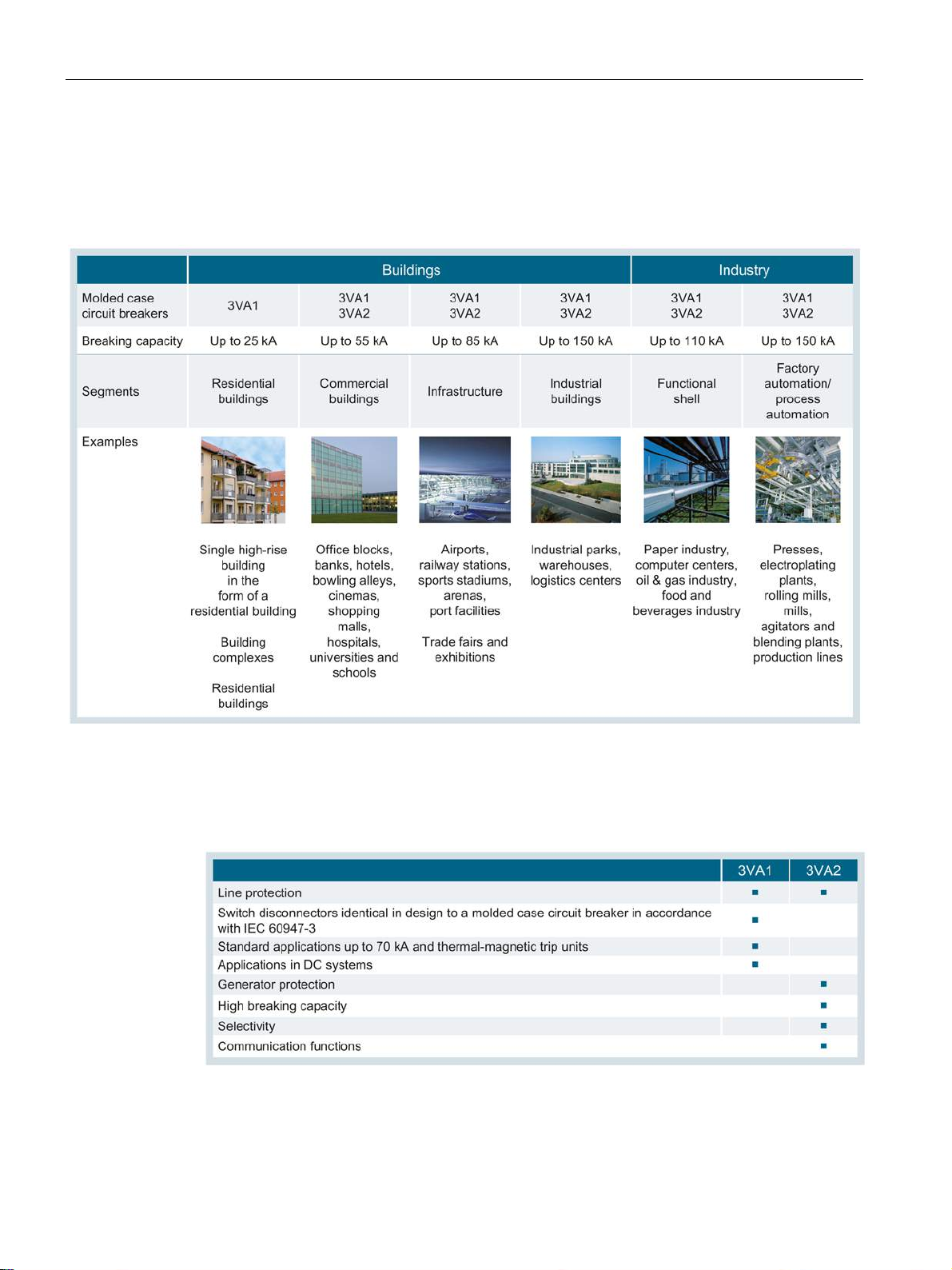
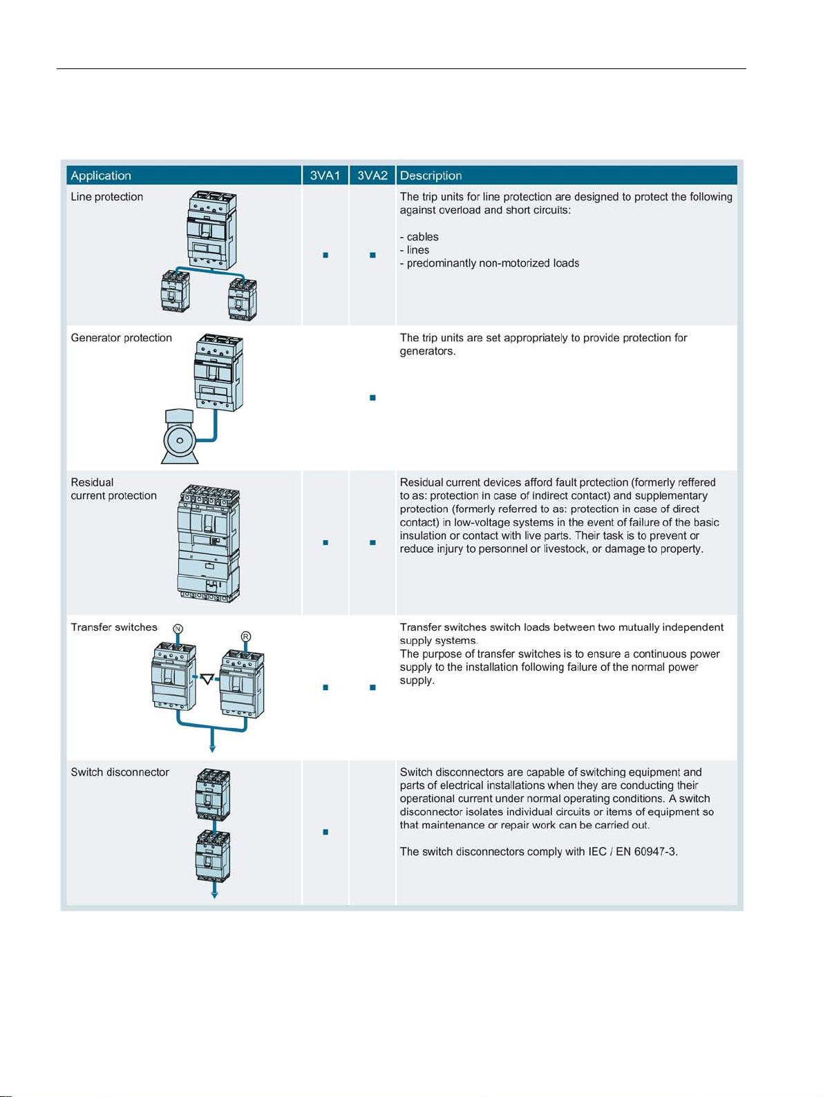
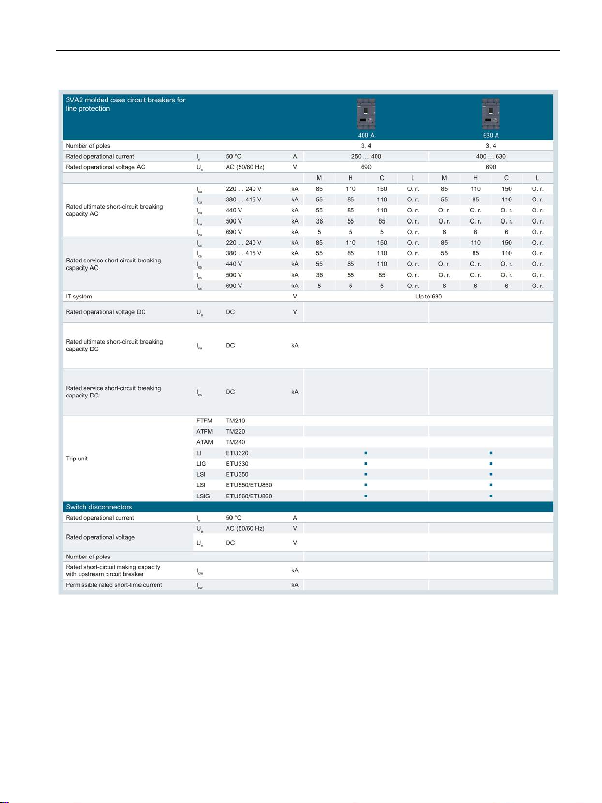
The two tables below show examples of applications and possible uses for the new 3VA
molded case circuit breakers.
3VA molded case circuit breakers
Manual, 04/2015, A5E03603177010-02
15
Page 16
Description
Possible uses
Functions and applications
2.1 Overview - applications and portfolio
3VA molded case circuit breakers can be deployed in various fields where they perform a
variety of different protection tasks. The following table (sorted according to breaking
capacity) shows the areas in which 3VA molded case circuit breakers are used:
3VA molded case circuit breakers are used in a variety of functions, as shown in the table
below:
3VA molded case circuit breakers
16 Manual, 04/2015, A5E03603177010-02
Page 17
Description
2.1.2
Portfolio
Sizes
2.1 Overview - applications and portfolio
Molded case circuit breakers are primarily designed for the following applications:
● Subdistribution systems
● Industrial distribution systems
● Final distribution systems
● On-site isolation
● Use in machines
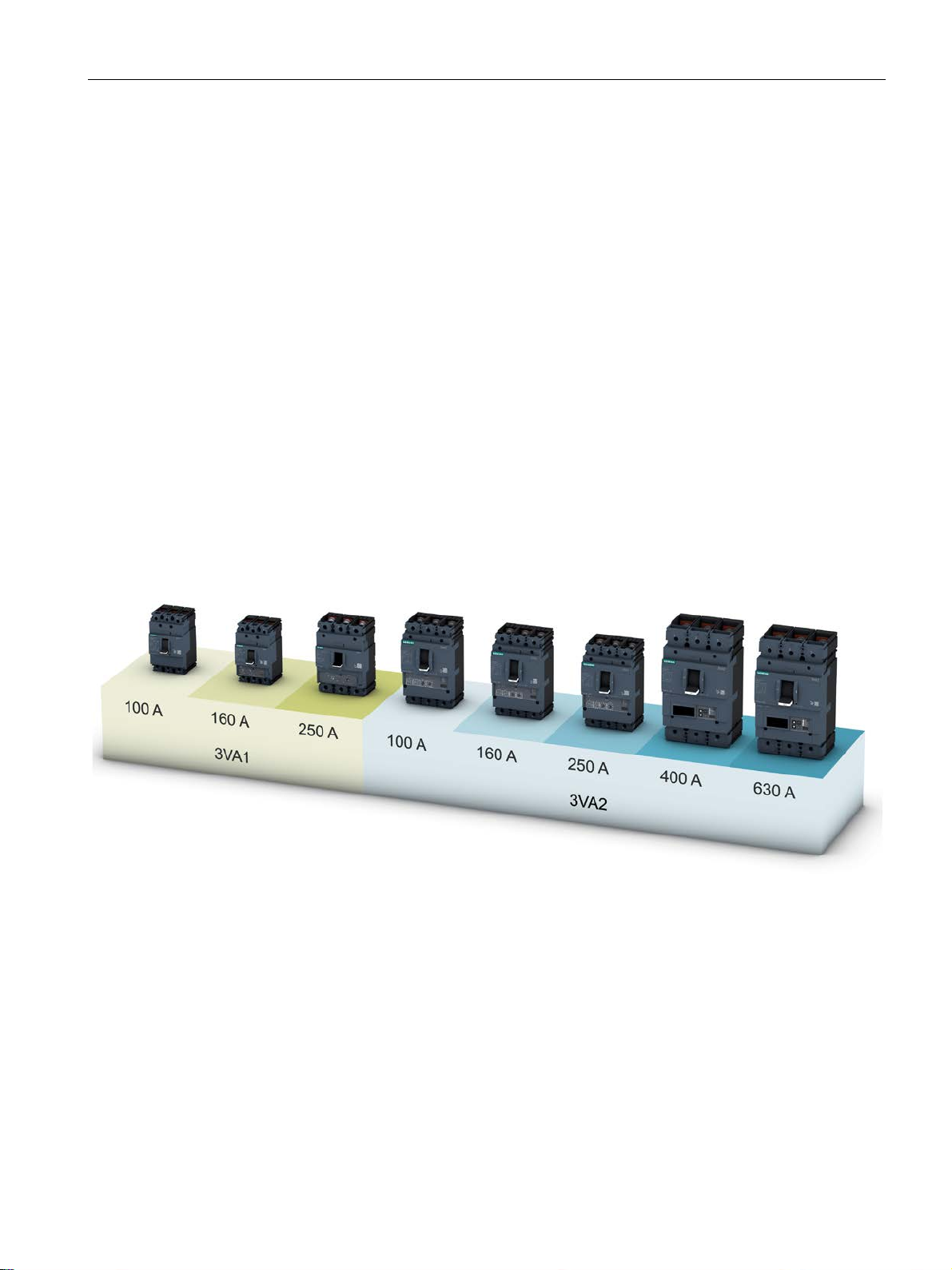
The integrated 3VA portfolio consists of two different series of molded case circuit breakers
in five different rated operational current versions (sizes).
The new 3VA molded case circuit breakers set new standards in flexibility and the variety of
modular accessories available. Standardized accessories suitable for use with several sizes
of circuit breaker from all the 3VA ranges help to cut costs and save time.
The new 3VA1 molded case circuit breakers are available in 1 to 4-pole versions (3VA1 160
A) or in 3 and 4-pole versions (3VA1 100 A or 3VA1 250 A). The new 3VA2 molded case
circuit breakers are available in 3 and 4-pole versions.
The circuit breakers are available with rated operational currents ranging from 16 A to 630 A
and rated voltages up to 690 V, depending on the series and size.
3VA molded case circuit breakers
Manual, 04/2015, A5E03603177010-02
17
Page 18

Description
3VA1 molded case circuit breakers
Features
Compact dimensions
Thermal-magnetic trip units
2.1 Overview - applications and portfolio
The new 3VA1 molded case circuit breakers reliably perform all the tasks associated with
line protection.
The key features of the 3VA1 series are:
● Compact design
● Depending on size: 1 and 2-pole versions in size 160 A, 3 and 4-pole versions in sizes
100 A, 160 A and 250 A
● Depending on size: Breaking capacity of 16 kA ... 70 kA at 415 V, 3 or 4-pole breakers
and 36 kA at 240 V,1-pole breakers
● Fixed-mounted, plug-in version
● Thermal-magnetic trip units
● AC/DC applications
● No derating up to +50 °C
● Modular and easy-to-fit internal accessories with diverse functions
● Uniform accessories platform across all 3VA molded case circuit breakers
Thanks to a mounting depth of 70 mm and a cover size of 45 mm, the 3VA1 molded case
circuit breakers of sizes 100 A, 160 A and 250 A are ideal for protecting cables and lines in
the plant area, especially for the INSTA electrical installation area. For these applications,
there is also a wide range of accessories available such as adapters for installation on DIN
rails, as well as residual current devices (RCD310 and RCD510) that can be side mounted.
3VA1 molded case circuit breakers are equipped with a thermal-magnetic trip unit which
provides overload and short-circuit protection. This has been developed for implementing
economical, cost-efficient installations up to 250 A. It is suitable for use in three-phase
networks, AC networks, 400 Hz applications, and with DC currents.
3VA molded case circuit breakers
18 Manual, 04/2015, A5E03603177010-02
Page 19

Description
3VA2 molded case circuit breakers
Features
2.1 Overview - applications and portfolio
The new 3VA2 molded case circuit breakers reliably perform all the tasks associated with
line and generator protection.
This series is designed for applications with more exacting requirements:
● Increased breaking capacity
● Excellent selective protection
● Integrated metering function
● Connection to a fieldbus communication system
The most important features of the 3VA2 series are:
● Compact dimensions
● 3 and 4-pole versions
● Four breaking capacity classes from 55 kA … 150 kA
● Fixed-mounting, plug-in technology, draw-out technology
● Depending on size: Selective tripping at rated operational current difference 1 : 2.5
● Electronic Trip Units
● Retrofittable communication for ETU 5-series and 8-series
● Depending on the ETU: Integrated metering function
● AC applications
● No derating up to +50 °C
● Modular and easy-to-fit internal accessories with diverse functions
● Uniform accessories platform across all 3VA molded case circuit breakers
● Electronic Trip Units (ETU) with different setting values
3VA molded case circuit breakers
Manual, 04/2015, A5E03603177010-02
19
Page 20

Description
Compact dimensions with function expansions
Selective contact system
Electronic Trip Unit (ETU)
2.1 Overview - applications and portfolio
In addition to its expanded functionality, the 3VA2 molded case circuit breaker also comes
with compact dimensions for fixed mounting, as a plug-in version and a draw-out version.
A cover size of 70 mm for the door cutout and a complete selection of breaking capacity
classes from 55 kA to 150 kA at 415 V AC provide the necessary flexibility for planning.
Despite its compact size, the circuit breaker offers the following benefits:
● Extremely high breaking capacity
● Extremely good selectivity
● Electronic trip units, versions with and without integrated metering function and optional
fieldbus communication interface
With its contact system, the 3VA2 molded case circuit breaker is designed for fast selectivity
tripping. The selective contact system ensures the following:
● Dynamic instantaneous short-circuit range
● High breaking capacity
● Selective protection response of the molded case circuit breakers in relation to each other
● Selective protection response of the molded case circuit breakers in relation to other
protection devices such as downstream low-voltage fuses, etc.
The current sensor of the 3VA2 comprises an iron-cored transformer for the internal power
supply and a Rogowski coil for precise current measurement. Each transformer can be
optimized accordingly for its specific task. Thanks to the high accuracy of current
measurement, the 3VA2 molded case circuit breaker is suitable for power/energy
measurement. In addition, finer adjustment of ground fault current monitoring is possible.
The Electronic Trip Units (ETUs) provide the following protection functions:
● Overload protection L ("L" = Long-time delay)
Adjustable in steps from 40% to 100% of the rated operational current of the molded case
circuit breaker.
● Short-time delayed short-circuit protection S ("S" = Short-time delay) for time-selective
response in case of a short circuit
● Instantaneous short-circuit protection I ("I" = instantaneous):
● Protection of the neutral conductor against overload and short-circuit ("N" = neutral)
● Protection against residual currents to ground ("G" = Ground fault).
3VA molded case circuit breakers
20 Manual, 04/2015, A5E03603177010-02
Page 21

Description
Energy management and communication
2.1 Overview - applications and portfolio
The Electronic Trip Units (ETUs) provide the following energy management and
communication functions:
● Metering functions
● Communication
● Flexible, local, digital inputs and outputs via the EFB300 external function box
● Software commissioning support with powerconfig
● Testing and archiving with the TD300 and TD500 test devices (with powerconfig)
3VA molded case circuit breakers
Manual, 04/2015, A5E03603177010-02
21
Page 22
Description
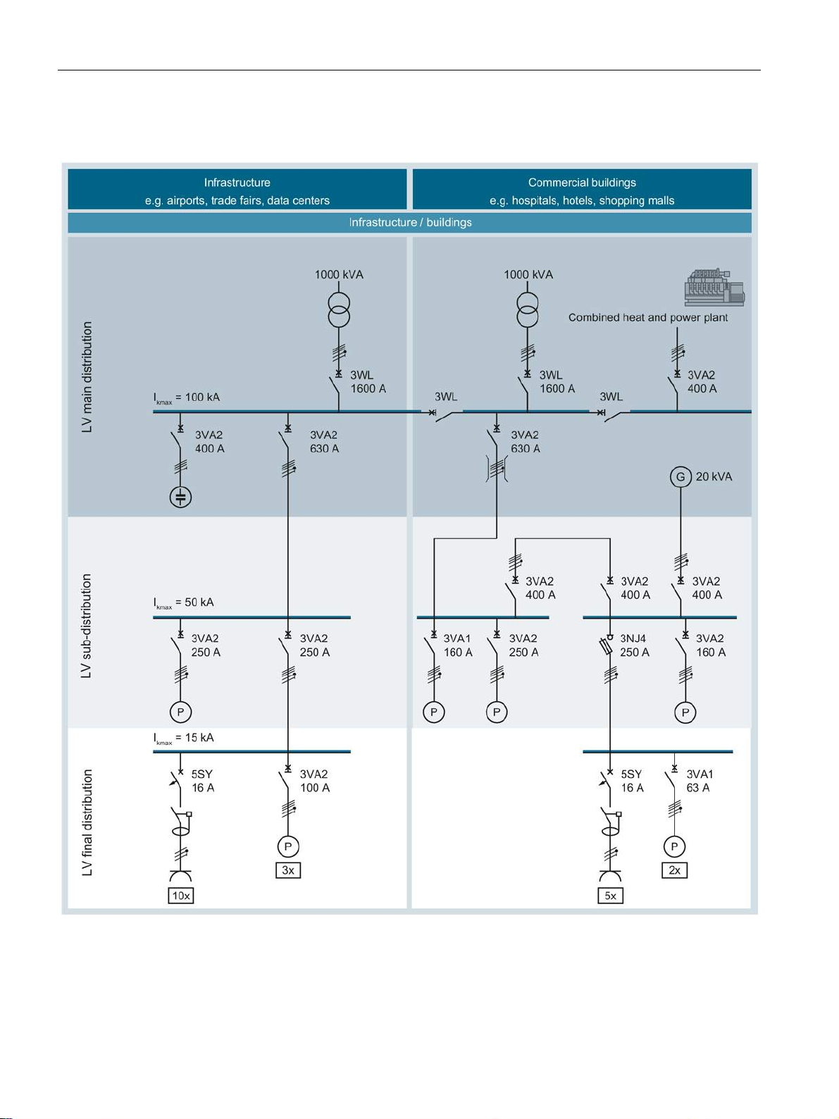
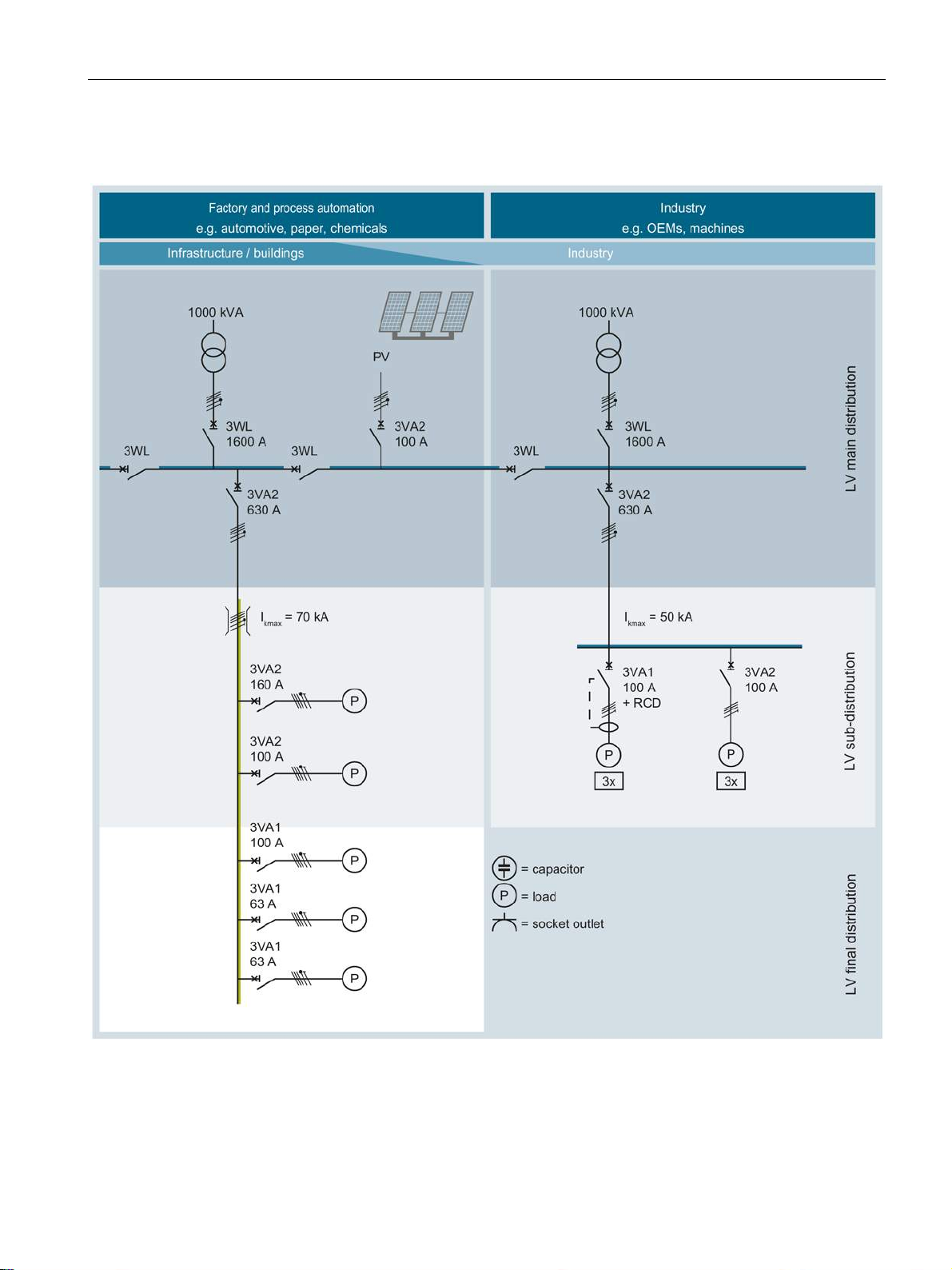
2.1.3
Application examples
2.1 Overview - applications and portfolio
3VA molded case circuit breakers
22 Manual, 04/2015, A5E03603177010-02
Page 23
Description
2.1 Overview - applications and portfolio
3VA molded case circuit breakers
Manual, 04/2015, A5E03603177010-02
23
Page 24
Description
2.1.4
Detailed information about applications and possible uses
See also
2.1 Overview - applications and portfolio
Applications (Page 105)
3VA molded case circuit breakers
24 Manual, 04/2015, A5E03603177010-02
Page 25
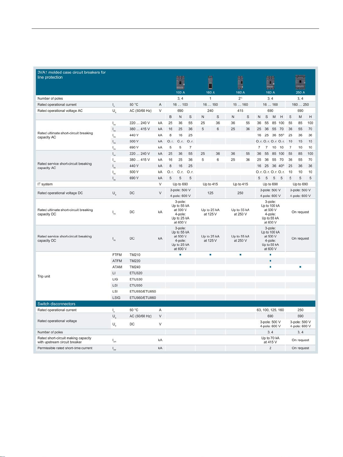
Description
2.1.5
Technical specifications
2.1 Overview - applications and portfolio
O. r. On request
1)
A side plate must be installed (see chapter Insulating equipment (Page 191)) if the installation conditions on the
right-hand side are such that the device is not finger-safe.
2)
In 125 A, 160 A: I
/ Ics = 36 kA / 36 kA
cu
3VA molded case circuit breakers
Manual, 04/2015, A5E03603177010-02
25
Page 26
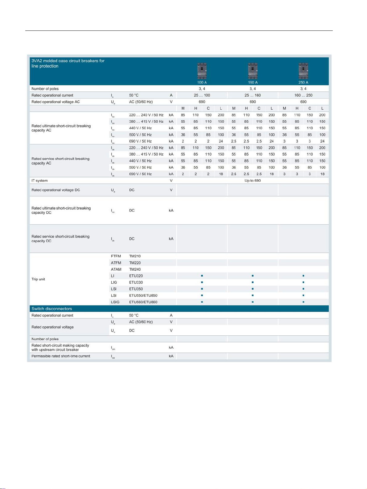
Description
2.1 Overview - applications and portfolio
3VA molded case circuit breakers
26 Manual, 04/2015, A5E03603177010-02
Page 27
Description
2.1 Overview - applications and portfolio
O. r. On request
3VA molded case circuit breakers
Manual, 04/2015, A5E03603177010-02
27
Page 28
Description
2.1.6
Molded case circuit breakers and accessories in the system
2.1 Overview - applications and portfolio
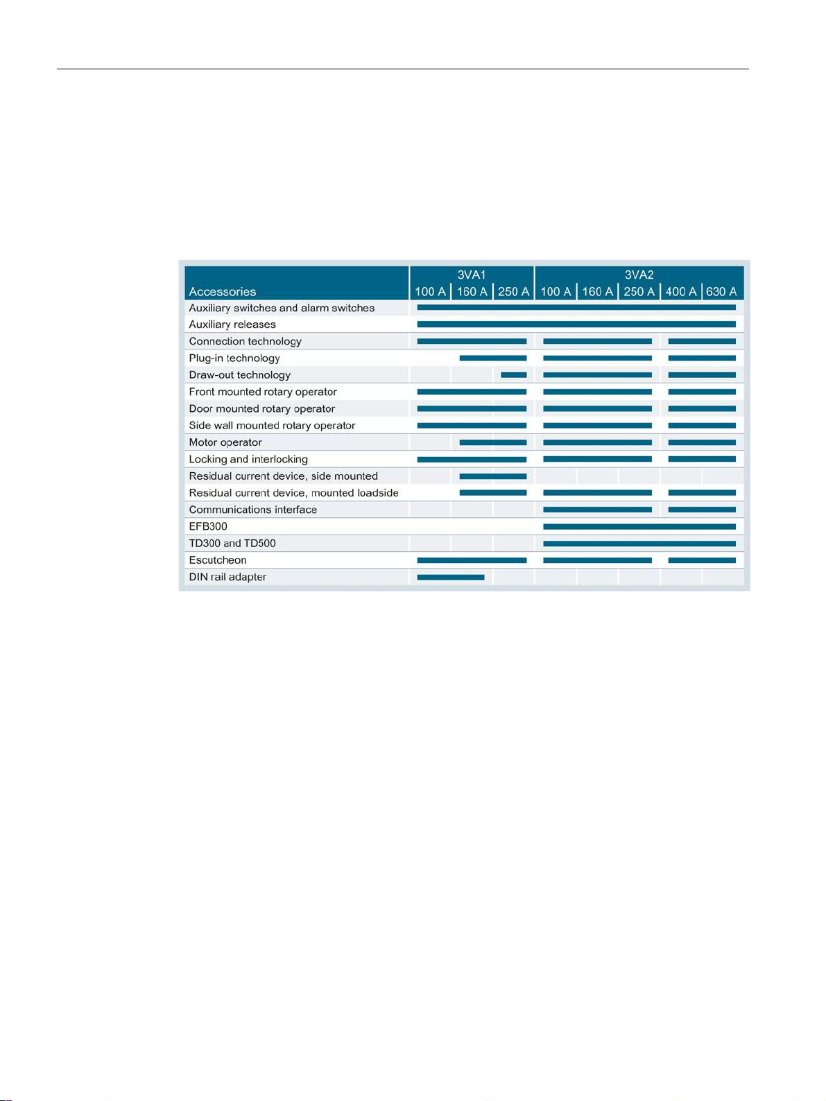
The new 3VA molded case circuit breakers come with a large portfolio of internal and
external accessories which can be installed flexibly in any size of circuit breaker (depending
on the type of accessory).
The table below indicates which accessories are compatible with particular molded case
circuit breakers, and which sizes of breakers are compatible with the same accessory:
3VA molded case circuit breakers
28 Manual, 04/2015, A5E03603177010-02
Page 29

Description
2.1 Overview - applications and portfolio
3VA molded case circuit breakers
Manual, 04/2015, A5E03603177010-02
29
Page 30
Description
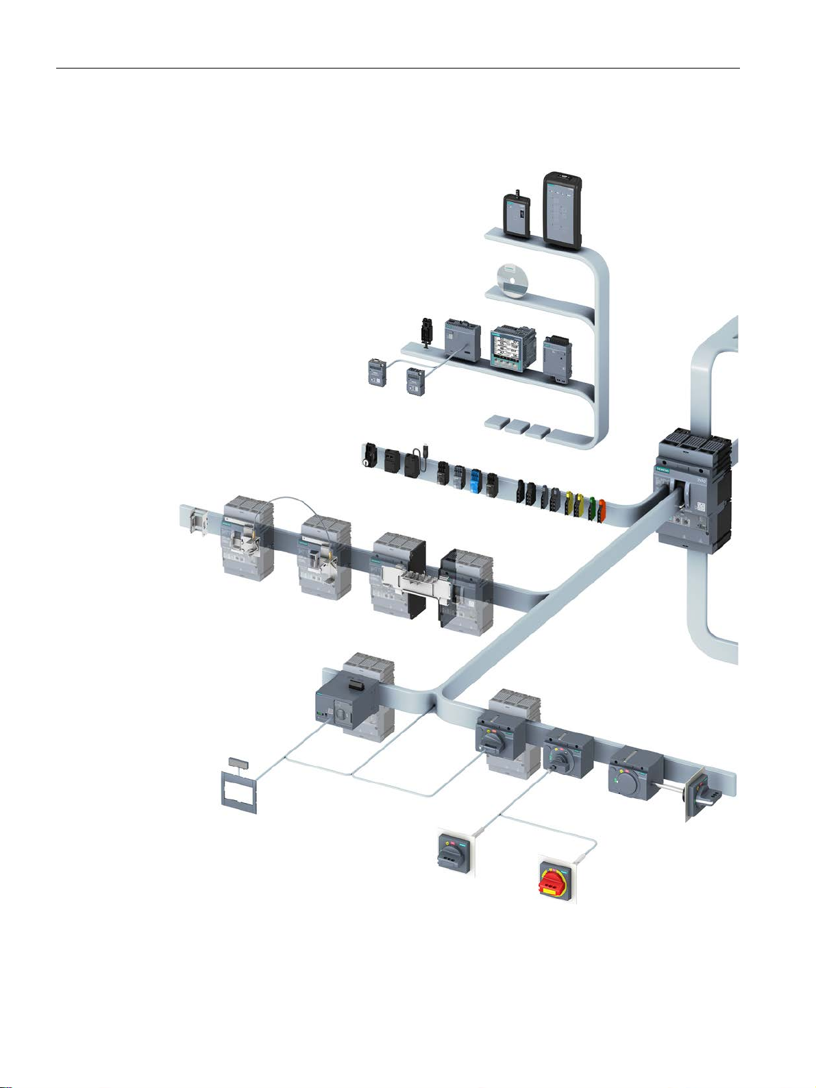
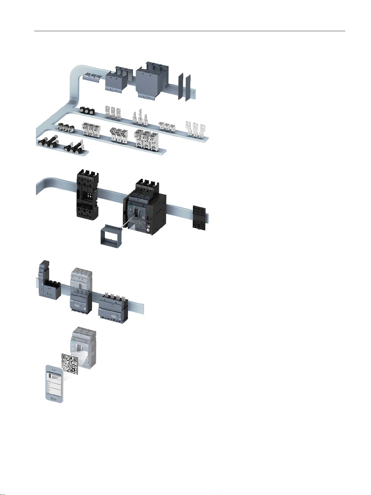
Overview of accessories in the system
2.1 Overview - applications and portfolio
3VA molded case circuit breakers
30 Manual, 04/2015, A5E03603177010-02
Page 31
Description
2.1 Overview - applications and portfolio
3VA molded case circuit breakers
Manual, 04/2015, A5E03603177010-02
31
Page 32

Description
2.2
Ergonomic design
Integrated system
2.2 Ergonomic design
This chapter provides an overview of the ergonomic design features of the new 3VA molded
case circuit breakers and explains what makes them so special.
The topics discussed in this chapter are listed below:
● Optional installation variants
● Color-coded indication of switching position in the draw-out unit
● Clear status indication
● Active illumination
● Ergonomic handle
● Color-coded control elements
● Broad range of accessories
● Connection options
With their technical features and functional scope, the new 3VA molded case circuit breakers
break new ground - but they also set new standards in ergonomic design.
When it comes to operation, functionality and installation, the new 3VA series is a fully
integrated system. This principle is embodied in the basic units and in all internal and
external accessories.
The benefits offered by the internal and external accessories available for the 3VA molded
case circuit breakers are:
● Standardized methods of operation
● Standardized scope of functions
● Standardized installation procedures
● Standardized accessories for all breaker versions from 100 A to 630 A (e.g. auxiliary
switches, auxiliary releases, etc.)
3VA molded case circuit breakers
32 Manual, 04/2015, A5E03603177010-02
Page 33
Description
2.2.1
The right circuit breaker for any installation conditions
2.2 Ergonomic design
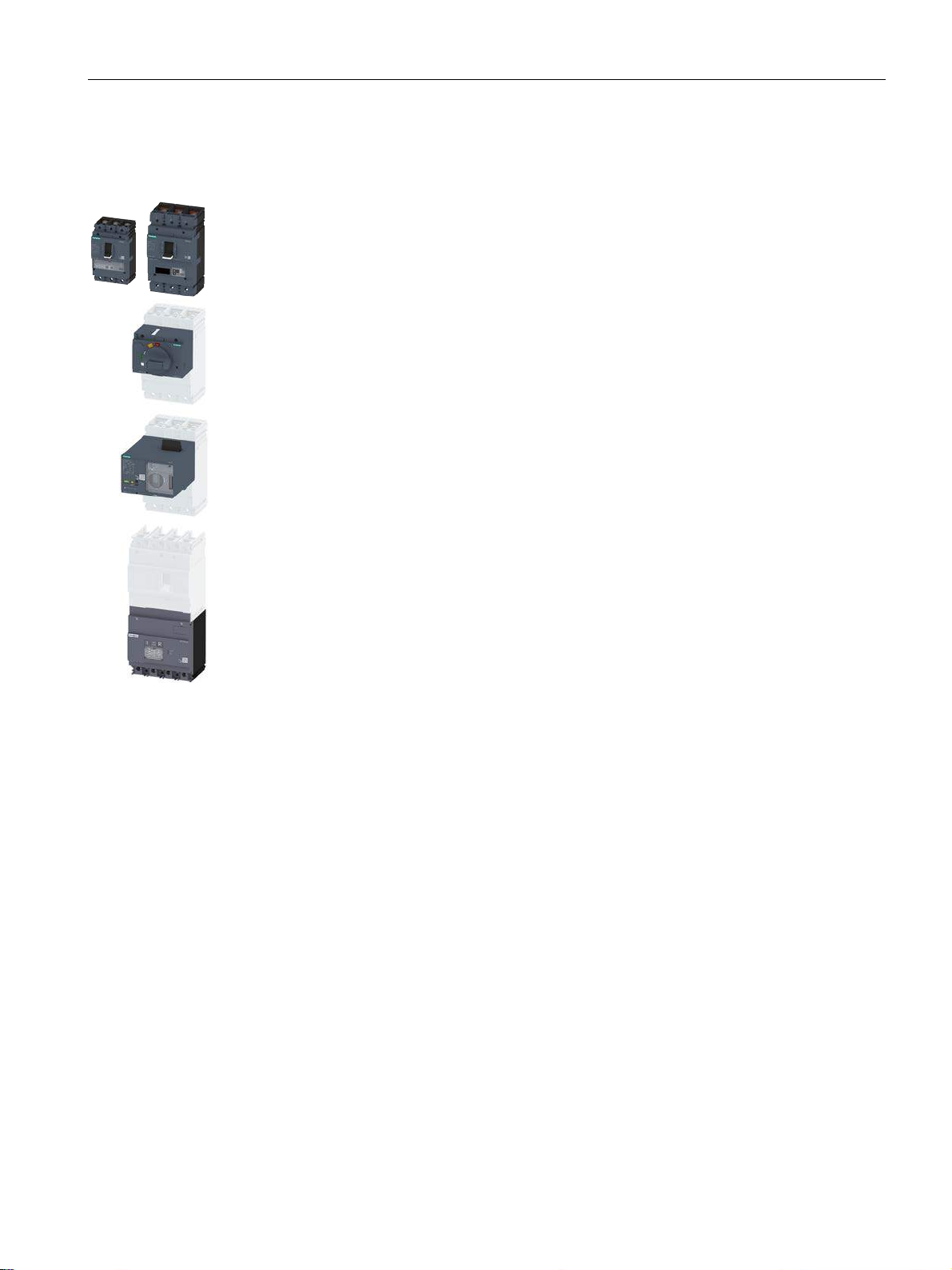
The new series of molded case circuit breakers can be equipped with additional components
so that they can be installed as fully functional switches in any location, a feature of the
product which affords maximum flexibility to system planners.
The following components can be installed to suit the installation location:
● Handle
● Front mounted rotary operator
● Door mounted rotary operator
● Side wall mounted rotary operator
● Motor operator
When the 3VA molded case circuit breaker is in the OFF position, it reliably disconnects all
current paths of the circuit in accordance with IEC 60947-2 and IEC 60204-1 (VDE 0113). In
the event of overvoltage between input and output, the reduced clearances prevent leakage
currents at the surface and ensure that the dielectric strength is not degraded.
The main switch functionality is not diminished by installation of the following accessories:
● Motor operator
● Manual operator
● Residual current device
3VA molded case circuit breakers
Manual, 04/2015, A5E03603177010-02
33
Page 34
Description
Optional installation variants
2.2 Ergonomic design
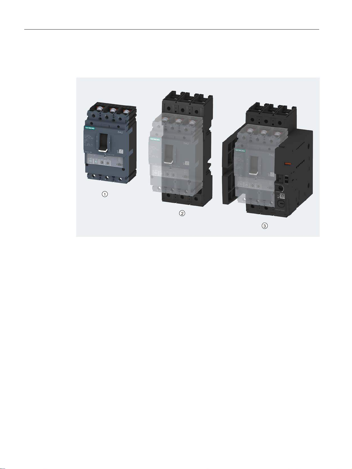
3VA molded case circuit breakers are available in the following installation variants:
● Fixed mounted ①
● Plug-in technology
● Draw-out technology
All variants offer the full range of functions, e.g. they can be equipped with every kind of
accessory. In addition, the last two variants are designed to allow speedy molded case
circuit breaker replacement for maintenance purposes or visual indication of the electrical
isolation in the main circuit.
②
③
3VA molded case circuit breakers
34 Manual, 04/2015, A5E03603177010-02
Page 35
Description
Indication of switching positions in the draw-out unit
2.2 Ergonomic design
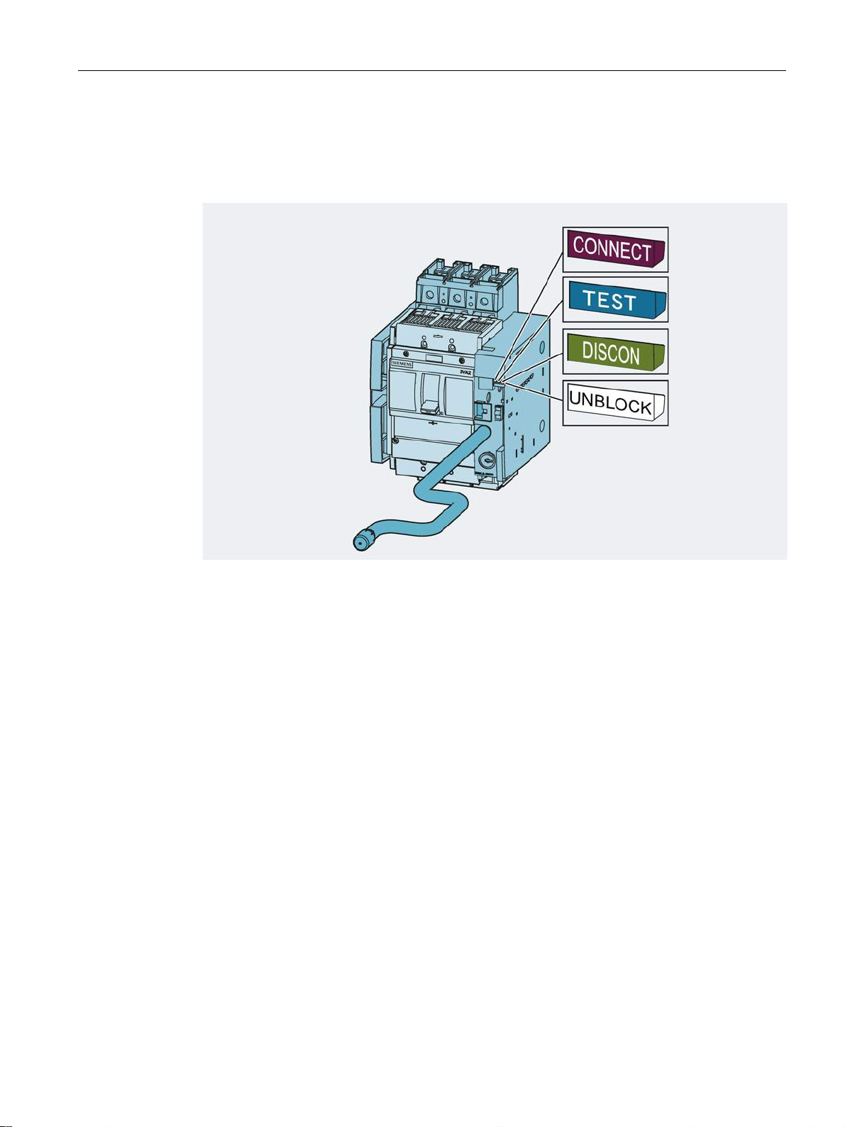
The picture below illustrates the colors used to indicate the switching position in the draw-out
unit:
The switching position is indicated in a window of the draw-out unit and is clearly colorcoded, enabling immediate identification of the current switching position of the molded case
circuit breaker.
The draw-out unit has three switching positions:
● CONNECT:
The molded case circuit breaker is connected to the main circuit.
● TEST:
In the TEST position, the main contacts of the molded case circuit breaker are not
connected to the main circuit, but only to the auxiliary circuit. It is therefore possible to
check that the auxiliary circuit is functioning properly when the main circuit is open.
● DISCONNECT:
The molded case circuit breaker is not connected to the main circuit nor to the auxiliary
circuit.
● UNBLOCK:
The molded case circuit breaker is not in any of the positions defined above and can be
moved by means of the crank handle.
3VA molded case circuit breakers
Manual, 04/2015, A5E03603177010-02
35
Page 36

Description
Motor operator for remote control
2.2.2
Ergonomic design of circuit breakers, handles and control elements
Ergonomic handle
2.2 Ergonomic design
3VA molded case circuit breakers can also be controlled remotely. Whether the circuit
breaker is controlled from "just" the other side of the closed cubicle door, or the breaker is
switched on via a control room, operator panel, etc., is irrelevant.
Motor operators are available as accessories for remote control of the circuit breakers.
With its wide surface area, the ergonomic handle is designed to assist manual operation of
the circuit breaker. The white strip around the edge of the handle makes it easy to identify in
conditions of poor visibility. The additional rated operational current information stamped on
the white strip also significantly eases identification of the circuit breaker when it is one of
many breakers in a large switchboard installation.
3VA molded case circuit breakers
36 Manual, 04/2015, A5E03603177010-02
Page 37
Description
Clear status indication
Active illumination
2.2 Ergonomic design
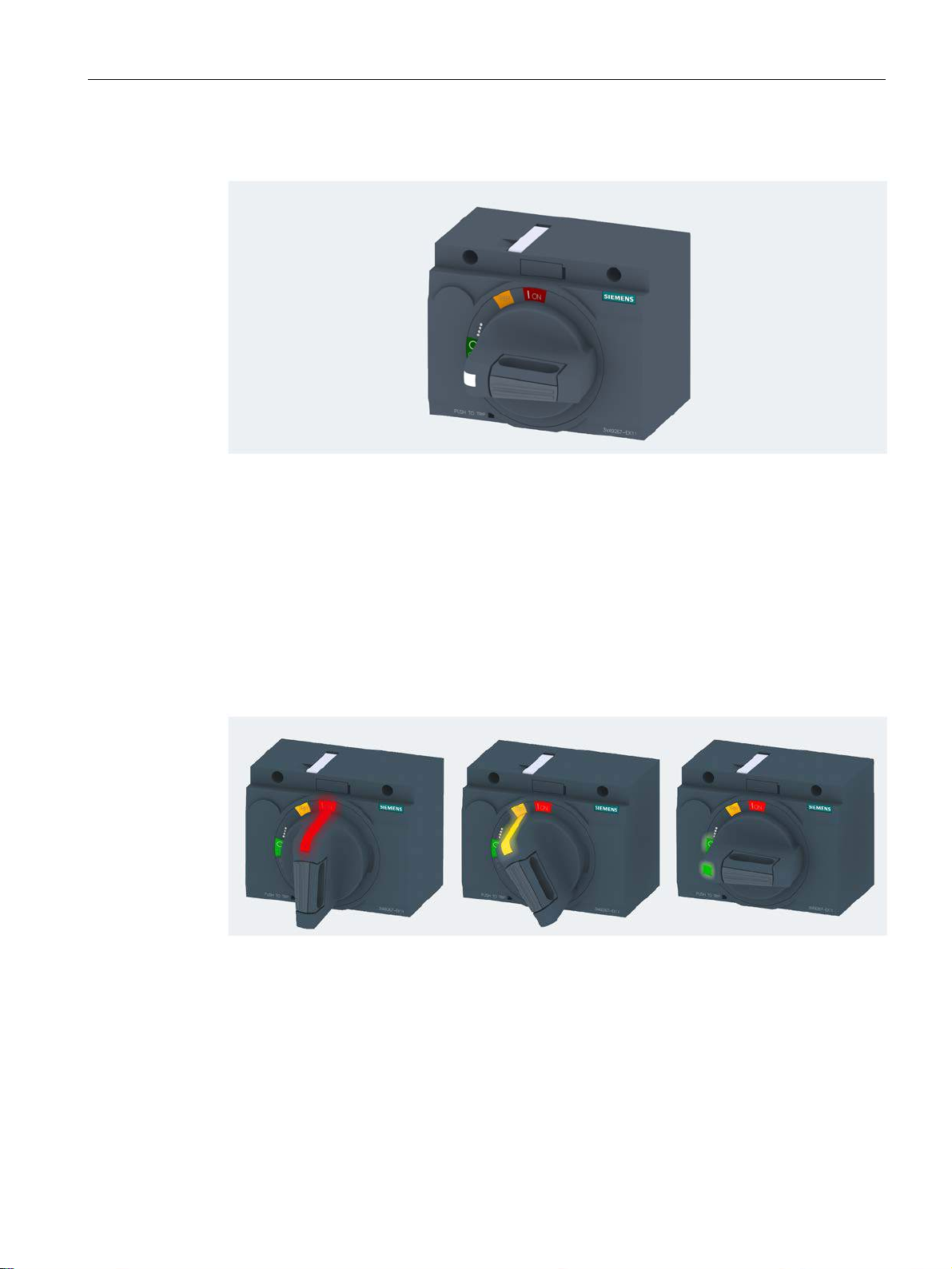
The possible switching positions of manual rotary operators are listed below:
● ON - red marking
● TRIP - yellow marking
● OFF - green marking
The handle clearly engages in one of these positions depending on the status of the molded
case circuit breaker. The switching positions are color-coded so that you can identify the
status of the circuit breaker at a glance.
You can retrofit an active illumination kit to manual rotary operators. The illuminated indicator
in the rotary handle signals the relevant switching position in the colors red, yellow and
green. This provides clear visualization of the switching position on-site in conditions of poor
visibility.
3VA molded case circuit breakers
Manual, 04/2015, A5E03603177010-02
37
Page 38
Description
Color-coded control elements
2.2 Ergonomic design
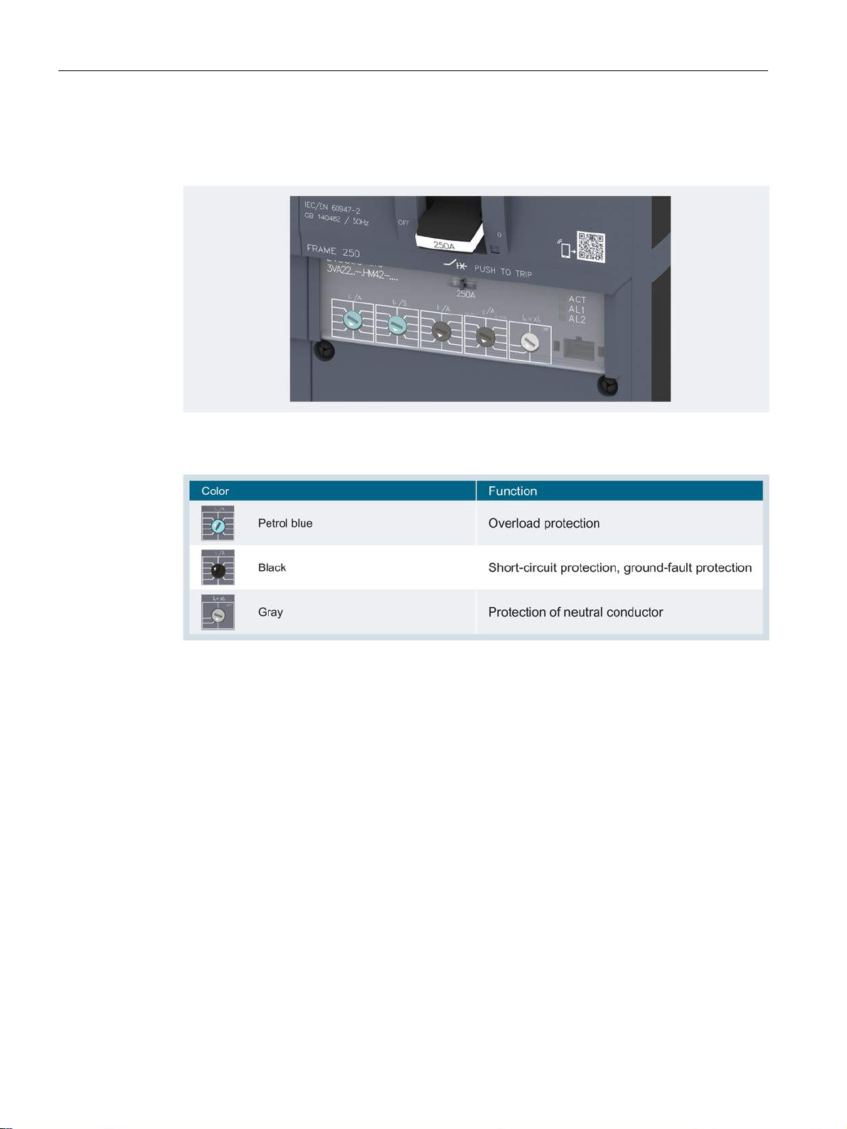
The control elements on the thermal-magnetic and electronic trip units are color-coded.
The color of each control element indicates that it performs a specific function, helping you to
make the required settings quickly.
3VA molded case circuit breakers
38 Manual, 04/2015, A5E03603177010-02
Page 39
Description
2.2.3
Wide range of accessories
Color coding of accessories
2.2 Ergonomic design
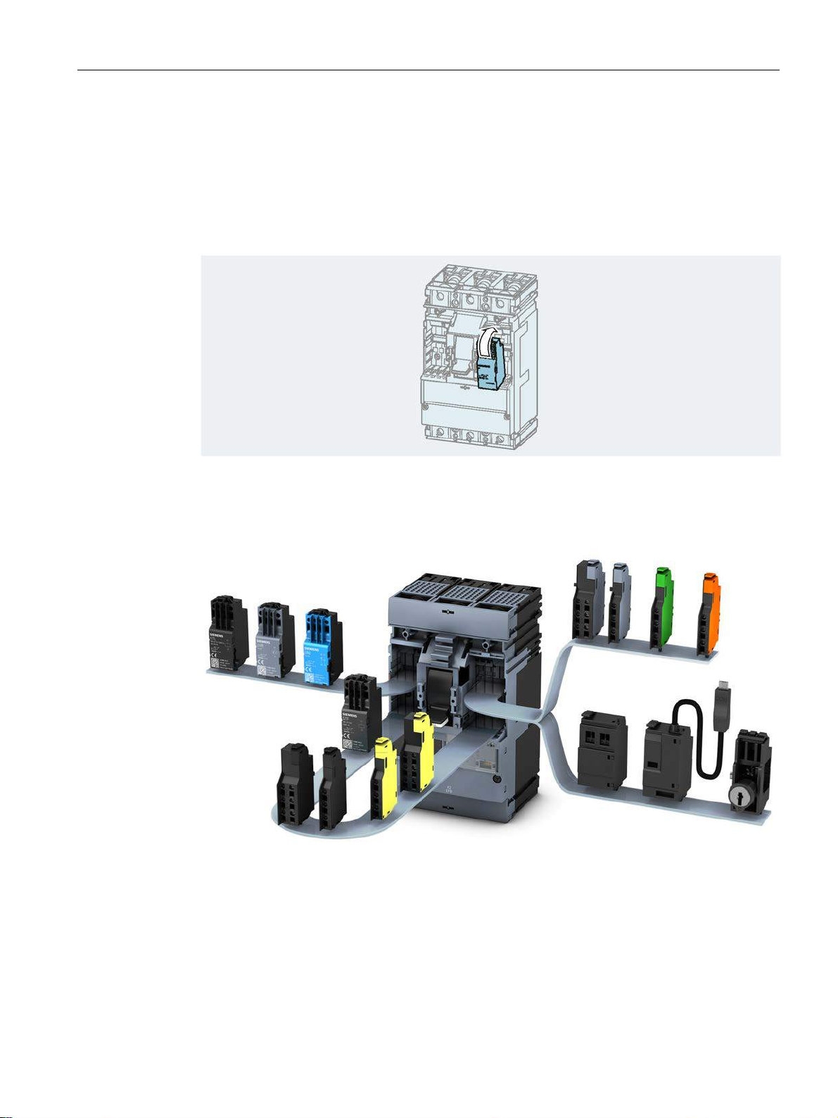
The internal accessories (e.g. alarm and auxiliary switches, auxiliary releases, etc.) all
belong to one family and can be installed on any size of 3VA1 or 3VA2 circuit breaker. The
accessories are designed for quick and easy installation. The components are coded by
color and design to ensure that they are always installed at the correct position in the circuit
breaker.
The internal accessories are color coded to clearly indicate their specific function.
A system of color coding has been used to clearly identify the specific functions of individual
accessories:
3VA molded case circuit breakers
Manual, 04/2015, A5E03603177010-02
39
Page 40
Description
Fast assembly of motor operators
2.2 Ergonomic design
The cylinder lock and communication accessories included with the internal accessories in
the picture above are explained in chapters Locking and interlocking (Page 269) and
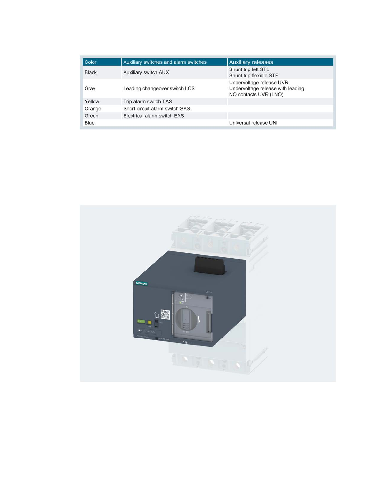
Communication and link-up to other systems (Page 360).
The motor operators have been designed for quick and easy assembly and disassembly.
The internal accessories are therefore easily accessible.
3VA molded case circuit breakers
40 Manual, 04/2015, A5E03603177010-02
Page 41
Description
2.2.4
Connection technology
①
⑦
②
⑧
③
⑨
④
⑩
⑤
⑪
⑥
⑫
2.2 Ergonomic design
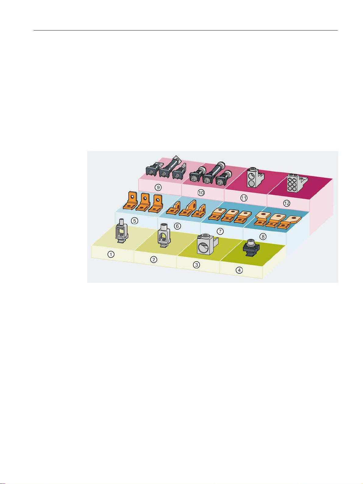
A large selection of connection systems is available for the new series of 3VA molded case
circuit breakers.
The supported cable cross-sections are based on the size of the molded case circuit breaker
and the cable terminals used. The terminals are fitted either internally or externally to the
molded case circuit breaker.
The connection technology is easy to integrate in the new series of 3VA molded case circuit
breakers.
With it you can implement various front and rear main conductor connections for the molded
case circuit breakers in all types of installation (fixed-mounted, plug-in and draw-out).
Box terminal
Circular conductor terminal
Circular conductor terminal, large
Lug terminal
Lug terminal, right-angled
Front connection bars edgewise
3VA molded case circuit breakers
Manual, 04/2015, A5E03603177010-02
Front connection bars extended
Front connection bars broadened
Rear terminal flat
Rear connecting stud
Circular conductor terminal for 2 cables
Circular conductor terminal for 6 cables
41
Page 42
Description
Cables and busbars
2.2 Ergonomic design
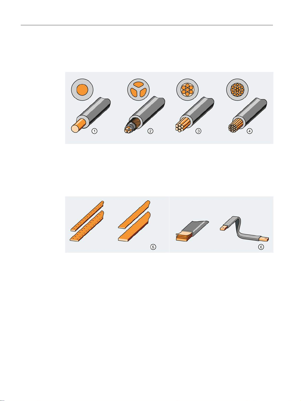
The new series of 3VA molded case circuit breakers are designed for connection to a variety
of different cables and busbars:
● Different cable types, e.g.
① Circular conductor
–
② Sector-shaped conductor
–
③ Stranded
–
④ Finely stranded
–
● ⑤ Busbars
– Rigid
– Laminated or flexible
⑥ Laminated copper bar
●
● Different materials
– Copper cables
– Aluminum cables
3VA molded case circuit breakers
42 Manual, 04/2015, A5E03603177010-02
Page 43

Description
2.3
Technical details
2.3 Technical details
A summary of the technical features of 3VA molded case circuit breakers can be found in
this chapter.
The topics discussed in this chapter are listed below:
● Circuit breaker identification
● Operation
● Design and components – 3VA1
● Design and components – 3VA2
● Current limitation
● Breaking capacity
3VA molded case circuit breakers
Manual, 04/2015, A5E03603177010-02
43
Page 44
Description
2.3.1
Circuit breaker identification
Circuit breaker labeling
①
④
②
⑤
③
2.3 Technical details
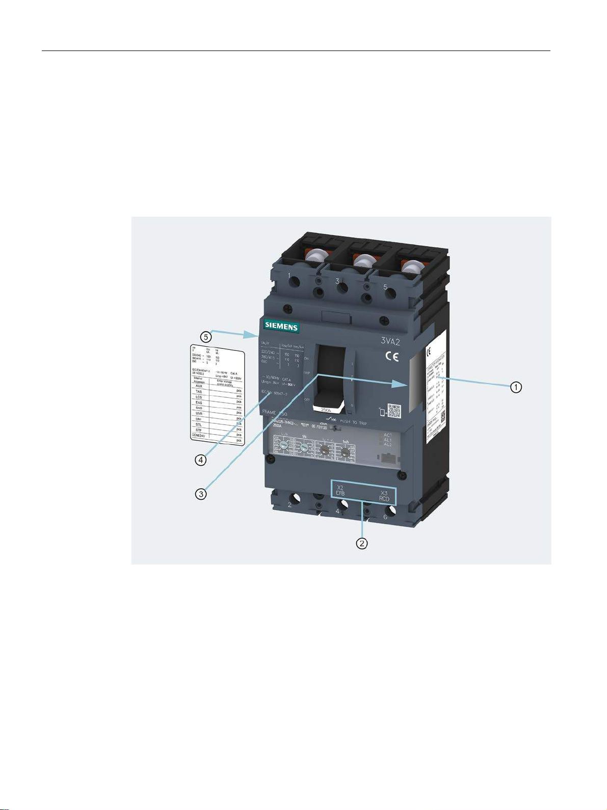
Each 3VA molded case circuit breaker can be clearly identified from various labels and
plates attached to the unit.
Each 3VA molded case circuit breaker has labels displaying all the important technical
information, enabling unique identification:
Connection information label
ETU connection designations
Label insert (in accessories compartment)
3VA molded case circuit breakers
44 Manual, 04/2015, A5E03603177010-02
Key electrical data
Internal accessories label
Page 45
Description
Front panel: Labeling
①
⑦
②
⑧
③
⑨
④
⑩
⑤
⑪
⑥
Knowledge Manager
2.3 Technical details
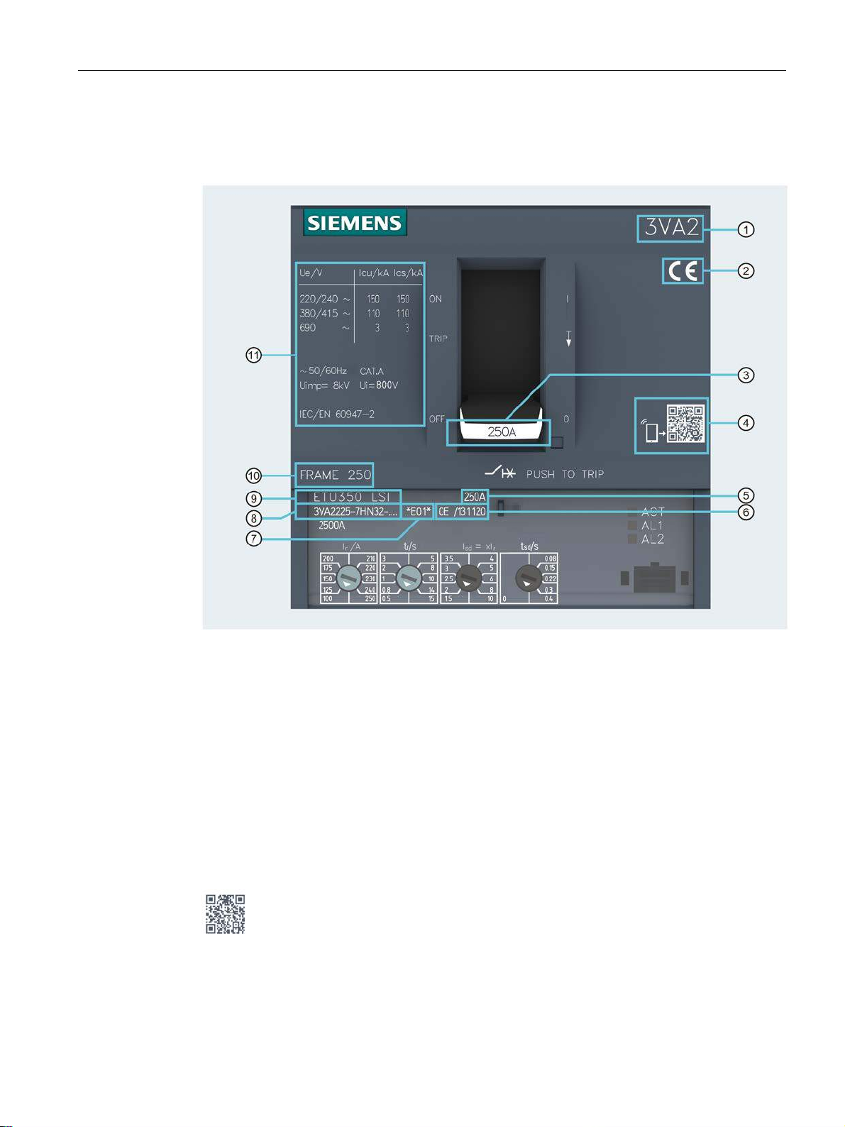
The following information is displayed on the front panel of the circuit breaker:
Circuit breaker designation
Approvals
Rated operational current
Knowledge Manager (see below)
Rated operational current
Date of manufacture
A QR code is attached in a clearly visible location to every 3VA molded case circuit breaker.
This code can be scanned with a smartphone or a tablet PC. For the full range of QR code
functions, use the "Industry Support" app supplied free of charge by Siemens.
It allows you to directly view or download all relevant product information.
Product version
Article number
Trip unit type
Size and breaking capacity class
Key electrical data
3VA molded case circuit breakers
Manual, 04/2015, A5E03603177010-02
45
Page 46

Description
①
③
②
④
2.3 Technical details
The key electrical data label on the molded case circuit breaker displays the following
information:
IEC breaking capacity values at various volt-
ages
Frequency, utilization category
Insulation data
Supported standards
3VA molded case circuit breakers
46 Manual, 04/2015, A5E03603177010-02
Page 47
Description
Connection information label
①
③
②
④
2.3 Technical details
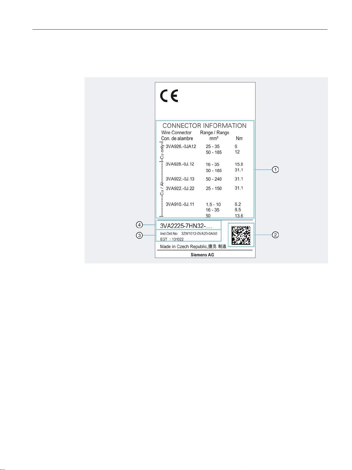
The connection information label displays the following information:
Information about cable connections
Code for production
Article number for operating instructions
Article number
3VA molded case circuit breakers
Manual, 04/2015, A5E03603177010-02
47
Page 48
Description
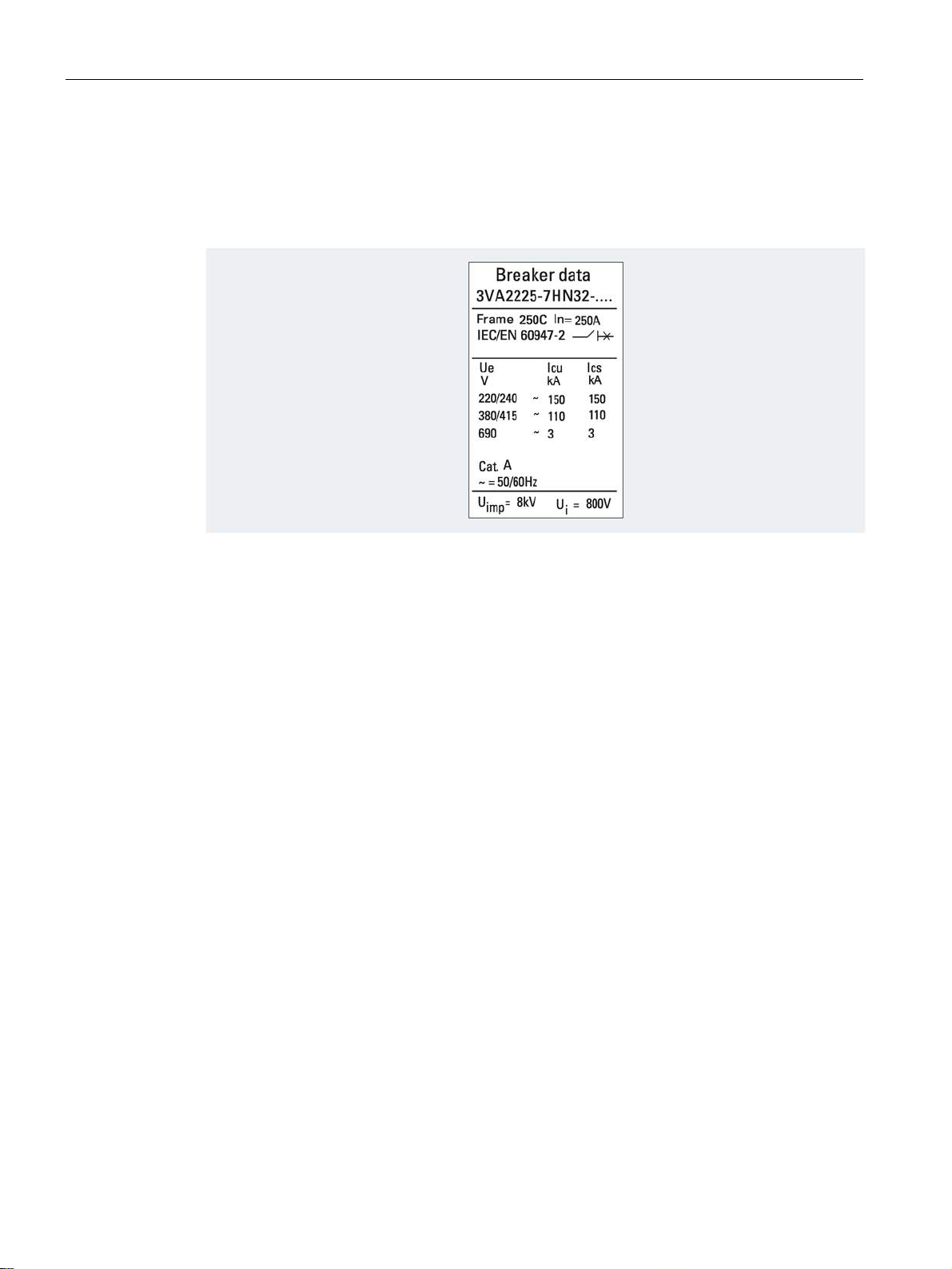
Label insert
2.3 Technical details
The label insert can be found in the right-hand accessories compartment. When an
accessory (e.g. motor operator or manual operator) is installed on the circuit breaker, this
label can be attached to the accessory.
The label insert displays the following information:
● Information about the molded case circuit breaker
● Article number
● Key electrical data
3VA molded case circuit breakers
48 Manual, 04/2015, A5E03603177010-02
Page 49
Description
Internal accessories label
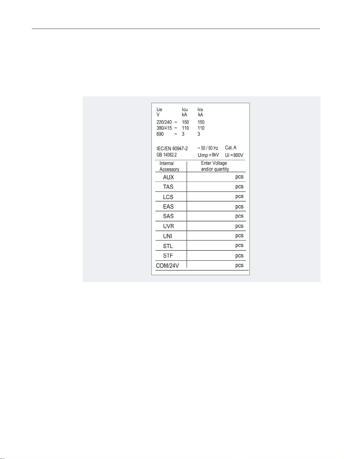
2.3 Technical details
You can make a note of the number of installed accessories on the internal accessories
label. This will enable you to ascertain which accessories are installed without removing the
lid of the accessories compartment and to use the information, for example, to reorder
components.
3VA molded case circuit breakers
Manual, 04/2015, A5E03603177010-02
49
Page 50

Description
2.3.2
Operation
①
ON: Main contacts closed
③
OFF: Main contacts open
②
TRIP: Switching position following a trip
④
PUSH TO TRIP: Initiates a mechanical trip
Reclosing the circuit breaker contacts from the TRIP position
Free tripping
2.3 Technical details
The main contacts of the molded case circuit breakers are opened and closed by means of a
handle mounted on the front of the unit. All contacts open and close simultaneously on all
3VA molded case circuit breakers in response to the following events:
● The handle is moved from OFF to ON.
● The handle is moved from ON to OFF.
● The tripping mechanism is activated by a trip unit.
● The tripping mechanism is activated by auxiliary releases (e.g. shunt trips, trip units).
Follow the steps below to reclose the circuit breaker contacts from the TRIP position:
1. Move the handle to the OFF position.
2. Move the handle to the ON position.
→ The breaker contacts are now closed.
All 3VA molded case circuit breakers have a free tripping capability. This function ensures
that the breaker cannot be prevented from tripping even if the operator blocks or is held
manually in the ON position or if the breaker is about to close.
Follow the steps below to test the free tripping function in order to verify that the breaker's
mechanical release system is working correctly:
1. Move the handle to the ON position.
2. Hold the handle in the ON position and press the button marked <PUSH TO TRIP>.
→ The circuit breaker trips and opens the main contacts.
→ The handle moves quickly into the TRIP position as soon as you release it.
Failure of the molded case circuit breaker to trip indicates that it is defective and must be
replaced.
3VA molded case circuit breakers
50 Manual, 04/2015, A5E03603177010-02
Page 51
Description
2.3.3
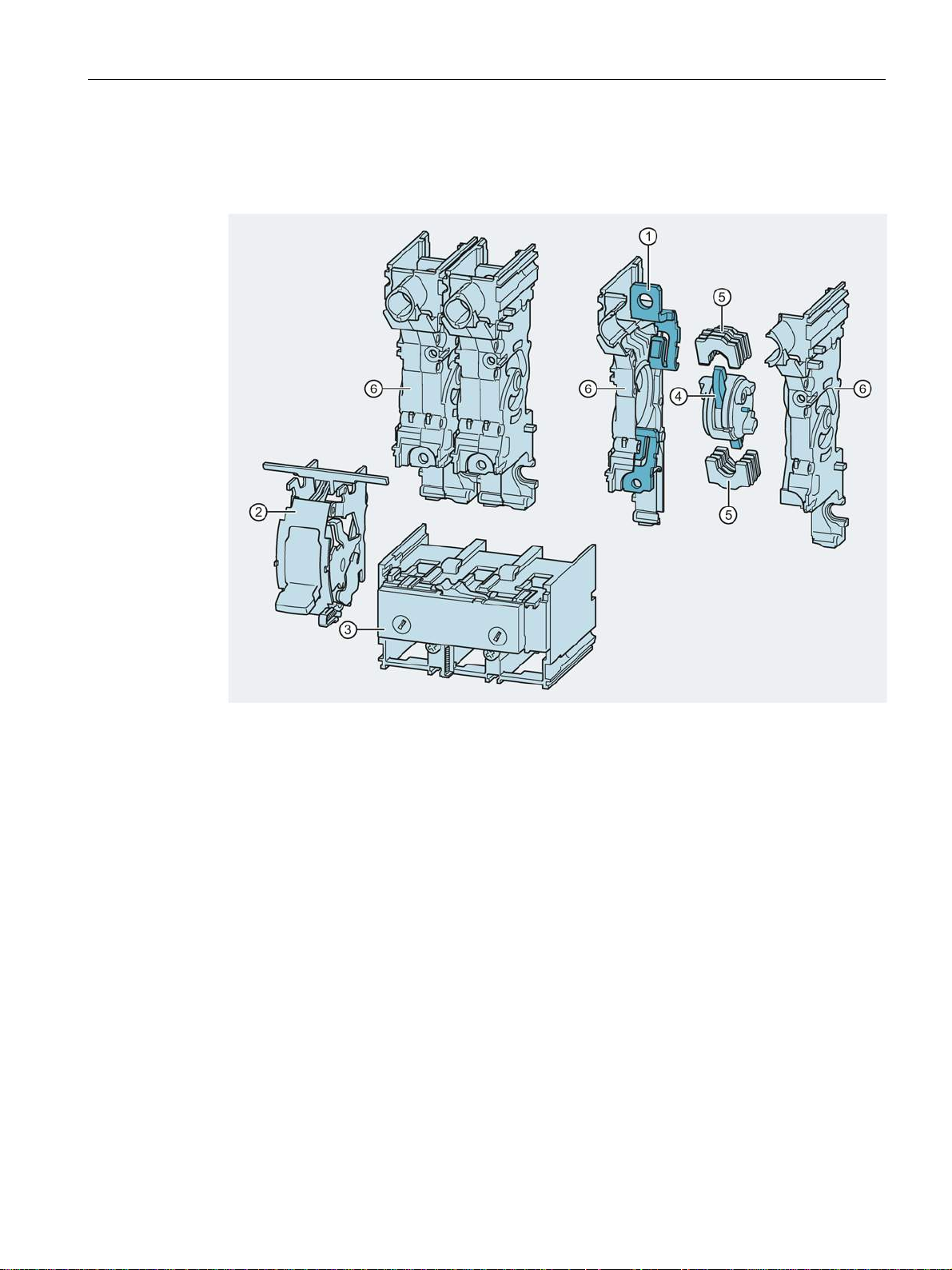
Design and components - 3VA1
①
④
②
Breaker mechanism with handle
⑤
Arc plates
③
⑥
2.3 Technical details
The design of the 3VA1 molded case circuit breaker is illustrated in the diagram below:
Main connections
Trip unit: TMTU
Rotary contact system
Pole cassette enclosure
3VA molded case circuit breakers
Manual, 04/2015, A5E03603177010-02
51
Page 52
Description
2.3.4
Design and components - 3VA2
①
⑤
②
⑥
③
⑦
④
2.3 Technical details
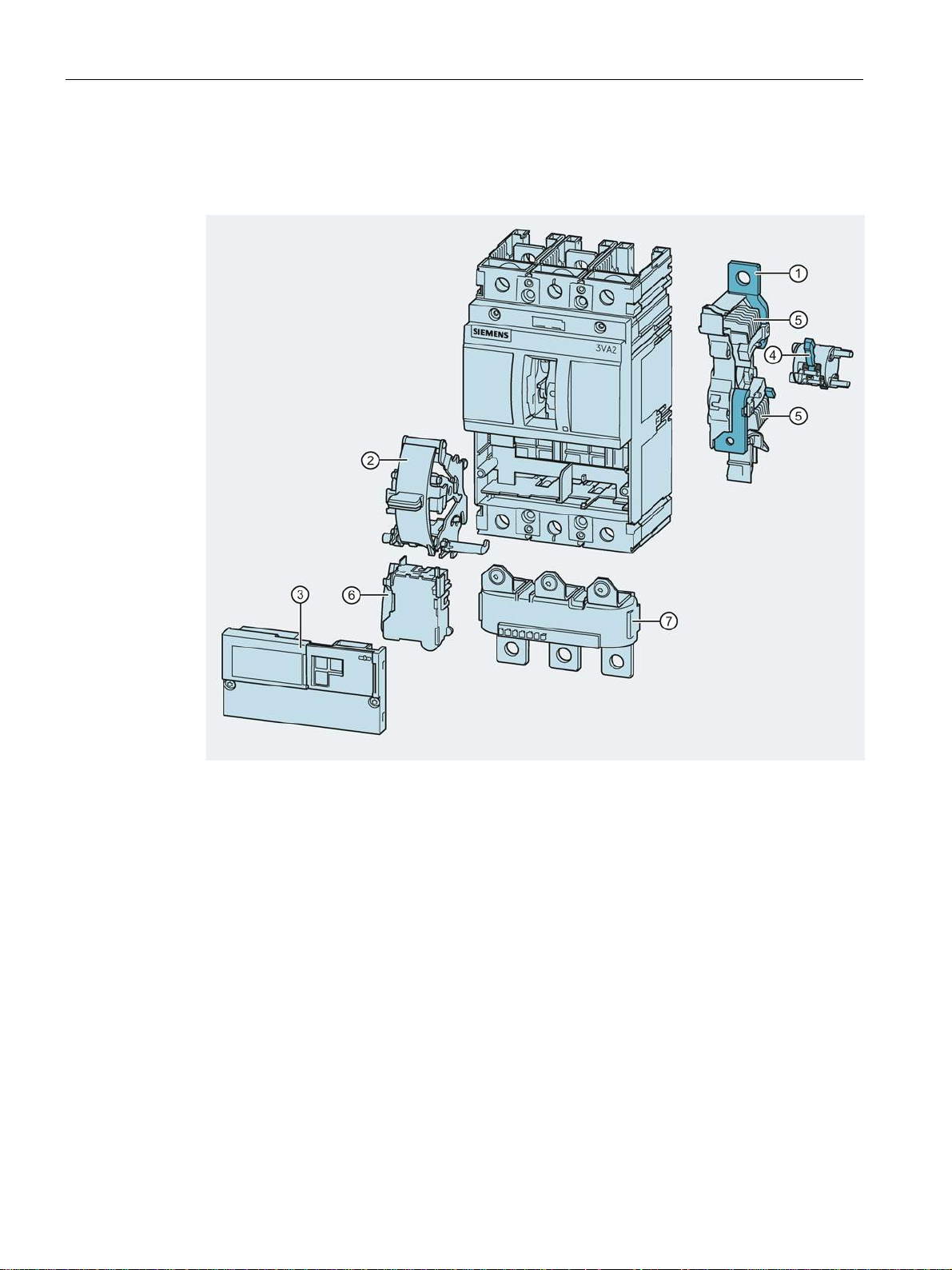
The design of the 3VA2 molded case circuit breaker is illustrated in the diagram below:
Main connections
Breaker mechanism with handle
Trip unit: ETU
Rotary contact system
3VA molded case circuit breakers
52 Manual, 04/2015, A5E03603177010-02
Arc plates
Maglatch
Current sensor
Page 53
Description
2.3.5
Current limitation
①
②
③
2.3 Technical details
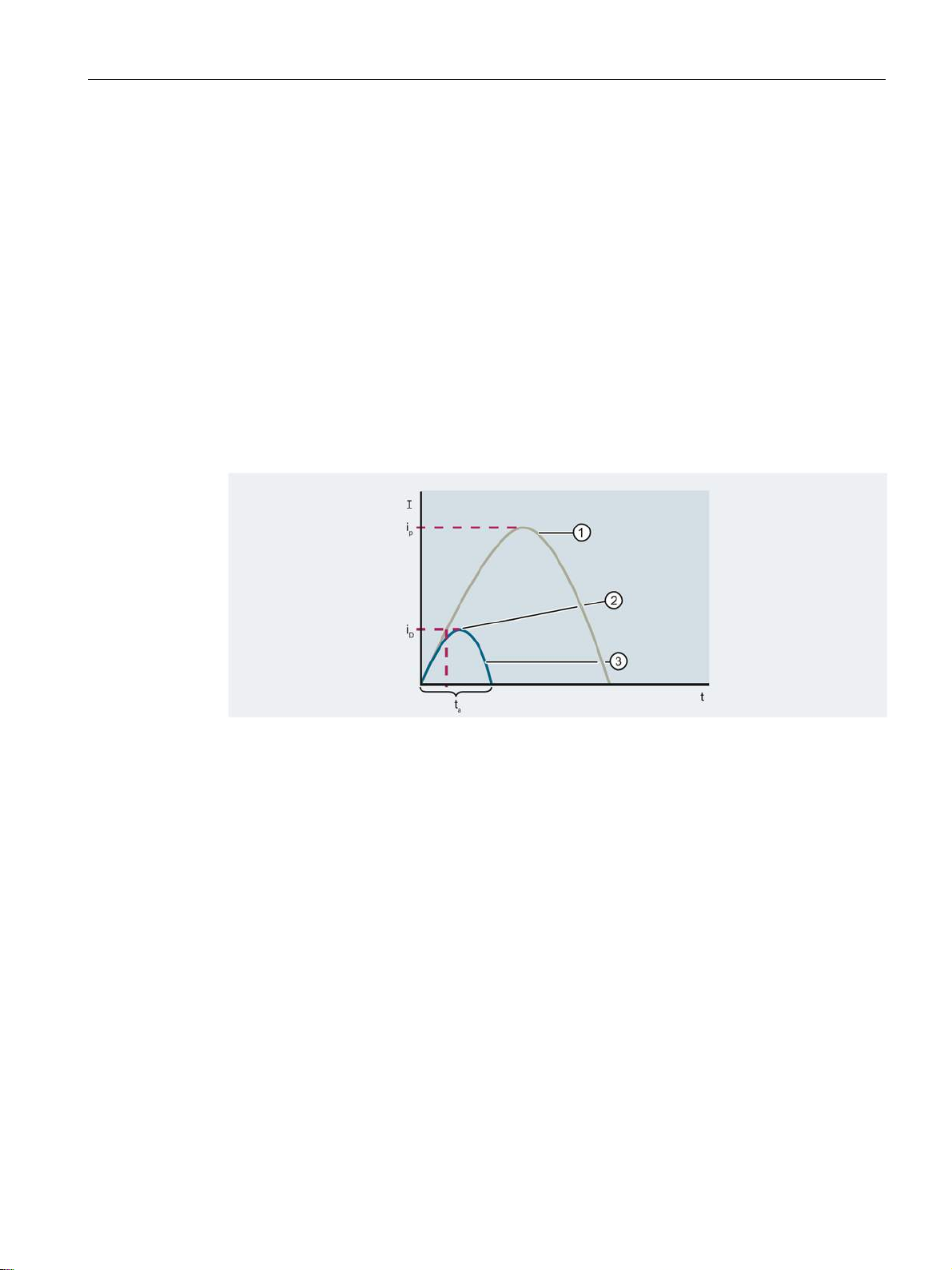
The term "current limitation" refers to the action of limiting the peak value of the prospective
impulse short-circuit current i
to a lower let-through current iD.
p
The compact design of the breakers has been made possible by their excellent current
limiting capabilities. In the event of a short circuit, the molded case circuit breaker
significantly reduces the magnitude of let-through current, i.e. it reduces the current loading
of downstream equipment (lower thermal load, fewer dynamic forces). The level of letthrough energy is also reduced to a considerable extent.
3VA molded case circuit breakers are designed with a current-limiting capability. IEC EN
60947-2 (VDE 0660-101), section 2.3, page 12, defines current-limiting molded case circuit
breakers in the following way:
"Circuit breaker that prevents the let-through current from achieving the prospective peak
value over a specific current range, and that limits the let-through energy (I
2
t) to a value that
is lower than the let-through energy of one half-wave of the symmetrical prospective current."
Unlimited current
Peak value of limited current
Limited current
Let-through current
i
D
i
Unlimited impulse short-circuit current
p
t
Break time
a
3VA molded case circuit breakers
Manual, 04/2015, A5E03603177010-02
53
Page 54

Description
Double-rotary contact system
①
②
③
2.3.6
Breaking capacity
2.3 Technical details
To achieve excellent current limiting, the 3VA molded case circuit breakers are equipped
with a double-rotatory contact system that opens dynamically on its own above the specified
disengaging currents on the principle of magnetic repulsion before the expected peak value
of the short-circuit current is reached. These limits have been coordinated and optimized to
suit the overall device characteristics. This substantially reduces the thermal and mechanical
loading on the molded case circuit breaker and the electrical installation.
Fixed contacts
Rotary contact system
Arc splitter chute
The switching pole cassettes are optimized for high breaking capacity, and their doublerotary contact system design enables extremely good current limiting thanks to the build-up
of peak arc voltage generated at both contacts in the event of a short-circuit. This results in
significant limitation of the let-through energy I²t and the let-through current.
The rated ultimate short-circuit breaking capacity Icu is the maximum value of the short-circuit
current which the protective device is capable of disconnecting in accordance with
regulations. Up to this value, the protective device is also allowed to be used in a network.
The new 3VA molded case circuit breakers are available with identical external dimensions
but various breaking capacity classes according to size and rated operational current range.
3VA molded case circuit breakers
54 Manual, 04/2015, A5E03603177010-02
Page 55

Description
Switching capacity of the 3VA1 series
Switching capacity of the 3VA2 series
2.3 Technical details
O. r. On request
1)
In 125 A, 160 A: I
/ Ics = 36 kA / 36 kA
cu
3VA molded case circuit breakers
Manual, 04/2015, A5E03603177010-02
55
Page 56
Description
2.4
Selectivity
Selective behavior
2.4 Selectivity
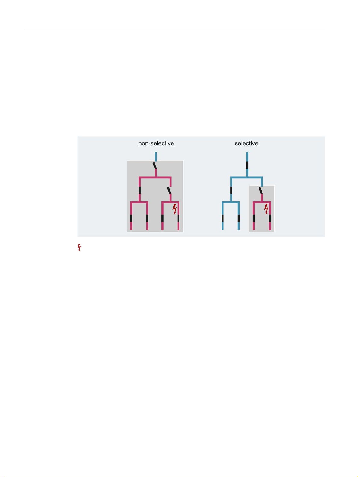
Switching devices connected in series, e.g. molded case circuit breakers and fuses, work in
a coordinated manner to ensure that switching devices are tripped successively. The closest,
upstream switching device before the location of the short-circuit must trip. The other
switching devices on the same current run do not trip. The purpose of selectivity is to
minimize the effects of a fault in terms of its duration and the area affected by the fault.
Selectivity is achieved when the circuit breakers are matched to each other by means of
selection, configuring and trip settings in such a way that, in the event of a fault, only the
breaker closest to the location of the fault trips.
The selective behavior of molded case circuit breakers is mainly influenced by the following
factors:
● Tripping value settings of the trip unit
● Tripping and break times
● Let-through current values
● Modes of switching of the relevant circuit breakers
Short-circuit location
– Zero-current interrupter
– Current limiter
3VA molded case circuit breakers
56 Manual, 04/2015, A5E03603177010-02
Page 57

Description
2.4 Selectivity
The selective behavior of circuit breakers can be implemented technically by a variety of
selectivity concepts:
● Current selectivity
The selectivity can be calculated in the overload range by comparing the time/current
characteristics. In the short-circuit range, this comparison leads to values that are too low.
The reason for this is that the trip unit behaves differently in the case of short-circuit
currents compared to its long-term behavior, e.g. in the case of overload.
If the short-circuit currents differ sufficiently at the installation points of two molded case
circuit breakers, the instantaneous short-circuit releases can normally be set such that if a
short-circuit occurs behind the downstream circuit breaker, only this downstream breaker
trips.
If the short-circuit currents are approximately the same at the installation points of the
molded case circuit breakers, the grading of the tripping currents of the short-circuit
releases only enables selectivity up to a specific short-circuit current .
This current is referred to as the ultimate selectivity value I
.
s
● Time selectivity
Selectivity can be achieved by time selectivity up to the threshold values of the
instantaneous short-circuit releases. To achieve this, the upstream circuit breaker
requires delayed short-circuit releases, so that in the event of a fault, only the
downstream circuit breaker will disconnect the part of the electrical installation affected by
the fault from the supply.
Both the tripping delays and the tripping currents of the short-circuit releases are graded.
● Zone-selective interlocking - ZSI
Selective behavior is achieved by installing parallel control cables between the molded
case circuit breakers. The electronic trip units then use a fast signal link to determine
priorities in the tripping sequence.
Zone Selective Interlocking (ZSI) has been developed by SIEMENS in order to prevent
unacceptably long tripping times when several molded case circuit breakers are
connected in series.
ZSI enables the tripping delay to be reduced to 50 ms for the circuit breaker upstream
from the location of the short circuit.
● Dynamic selectivity
This method is based on evaluation of the arc power which is generated in the arc chute
when the contacts open dynamically in response to a short circuit. During this process, a
smaller sized downstream molded case circuit breaker converts more energy in the arc
chute than the larger, upstream molded case circuit breaker. A selective trip unit
evaluates the energy conversion in both molded case circuit breakers. The downstream
molded case circuit breaker trips, while the contacts of the upstream circuit breaker close
again. Since both molded case circuit breakers perform a current limiting function, the
residual current limit imposed in practice is higher than the limiting action specified for the
individual molded case circuit breakers.
3VA molded case circuit breakers
Manual, 04/2015, A5E03603177010-02
57
Page 58

Description
Full selectivity
Partial selectivity
Selectivity with 3VA2 molded case circuit breakers
2.4 Selectivity
There is an increasing demand for full selectivity in order to safeguard continuity of service
by power distribution systems. A power system is said to be fully selective if only the
protective device located upstream of the fault location when viewed in the direction of
energy flow, i.e. from the infeed to the load, trips in the event of a fault.
Full selectivity always refers to the short-circuit current occurring at the installation point.
A system is said to be partially selective when selective tripping in response to a system fault
is not ensured up to the maximum ultimate short-circuit breaking capacity I
devices. Selectivity is then ensured only up to a certain I
current value (ultimate selectivity
s
value). If the calculated prospective short-circuit current at the location of installation of the
downstream protective device is lower than the ultimate selectivity value specified for the
switching devices, then it is still possible to describe the system as fully selective.
If the values determined by the short-circuit current calculation (e.g. according to IEC/EN
60909, DIN VDE 0102) at the installation point of the downstream circuit breaker lie below
the ultimate selectivity value listed in the respective table for the selected combination,
selectivity is assured for all possible short circuits at the installation point.
of the switching
cu
If the calculated short-circuit current at the installation point is higher than the ultimate
selectivity value, selective tripping by the downstream circuit breaker is only assured up to
the value listed in the table. A judgment must be made as to whether the value can be
considered to be sufficient because the probability of the maximum short-circuit occurring is
low, for example. Otherwise, a circuit breaker combination should be chosen whose
selectivity limit lies above the maximum short-circuit current.
Series 3VA2 circuit breakers are designed to deliver excellent selective tripping combined
with optimum current limiting and outstanding breaking capacity.
3VA2 molded case circuit breakers have been specifically designed to meet the following
requirements:
● System-wide, high selectivity with a rated operational current differential of 1 : 2.5 up to
the miniature circuit breaker
● Selectivity in combination with high current limiting and high breaking capacity
● Cost-effective design / configuring of selective power distribution systems
These molded case circuit breaker requirements are achieved in engineering terms as
follows:
● Rotary, double-break contact system for highly dynamic opening response
● Coordinated electronic trip units
● Dynamic selectivity
3VA molded case circuit breakers
58 Manual, 04/2015, A5E03603177010-02
Page 59

Description
Electronic trip units and fast trip units
2.5
Standards and guidelines
2.5.1
Compliance with standards
2.5 Standards and guidelines
Depending on use of molded case circuit breakers with a rated operational current
differential in a ratio of at least 1 : 2.5 and selection of suitable breaking capacity classes,
you can achieve selective tripping of the area of the installation directly affected by the fault
up to the maximum ultimate short-circuit breaking capacity.
You can find information on selectivity values for 3VA2 molded case circuit breakers on the
Internet under the link for 3VA documentation (
Documentation).
As a protective device, the molded case circuit breaker is required to clear electrical faults in
the system. For this purpose, series 3VA2 circuit breakers are equipped with intelligent
electronic trip units which can be combined with metering functions.
The tripping characteristic of the electronic trip units can be finely and flexibly adjusted. In
the event of short circuits, a fast trip unit also responds according to the arc power from the
arc chute. This selective trip unit ensures that major short circuits are cleared more quickly,
while at the same time ensuring that medium short circuits are interrupted selectively.
http:/www.siemens.com/3VA-
All the standards and guidelines with which 3VA molded case circuit breakers comply are
summarized in this chapter.
The topics discussed in this chapter are listed below:
● Compliance with standards
● Electromagnetic compatibility
● Ambient conditions
● Degrees of protection
The standards fulfilled by the 3VA molded case circuit breakers include:
● IEC / EN 60947-1
● IEC / EN 60947-2
● IEC / EN 60947-2, Annexes B, H and M
● IEC / EN 60947-3
● IEC / EN 60947-6-1
3VA molded case circuit breakers
Manual, 04/2015, A5E03603177010-02
59
Page 60

Description
2.5.2
Electromagnetic compatibility
2.5.3
Certificates
2.5.4
Ambient conditions
Pollution degree
Ambient temperature
Special climatic requirements
2.5 Standards and guidelines
The 3VA molded case circuit breakers meet the requirements of the following standards:
● CISPR11, Class A and Class B
● IEC / EN 60947-1, Appendix S
● IEC / EN 60947-2, Appendices B, F, J and N
The 3VA molded case circuit breakers are adequately resistant to the following factors:
● Electrostatic charge
● Electrostatic discharge
● Electromagnetic waves, e.g. from transmission systems, mobile phones, radio telephone
sets and radar systems
● Overvoltage, e.g. caused by lightning
● Voltage surges
You can find information on the available certification (CE, UL, CSA, FM, marine approvals)
on the Internet (http://support.automation.siemens.com/WW/view/en/54137334/134200
In the Entry List you can use the certificate type (general product approval, explosion
protection, test certificates, shipbuilding, etc.) as a filter criterion.
Operation of the 3VA1 and 3VA2 molded case circuit breakers is approved in accordance
with IEC / EN 60947-1 and IEC / EN 60664-1 for pollution degree 3.
3VA molded case circuit breakers are used at ambient temperatures from -25 °C to +70 °C.
Derating (reduction in rated operational current) is required at temperatures above +50 °C.
You will find more information on the applicable derating factors in chapter Derating and
temperature compensation (Page 489).
The permissible storage temperature in original Siemens packaging lies between -25 °C and
+80 °C.
).
3VA molded case circuit breakers including their accessories can also be used in
challenging operating environments.
3VA molded case circuit breakers
60 Manual, 04/2015, A5E03603177010-02
Page 61

Description
Harsh conditions of storage, transportation and stationary use
Class E
Vibration resistance and shock resistance
2.5 Standards and guidelines
The molded case circuit breakers have been tested according to the relevant special test
procedures defined in IEC / EN 60947-1, Appendix Q for
applications.
This class covers the areas MC3 + CC2 + SC1:
● Ambient temperature
● Humidity
● Vibration environment
● Shock environment
These ambient conditions can be referred to as "Open deck, damp and cold atmosphere
without salt spray" or "Difficult, non-marine conditions".
The following standards-related criteria are complied with:
● IEC / EN 60068-2-2 "Bd" and IEC / EN 60068-2-1 "Ab":
Temperature range: -25 °C … +70 °C
● IEC / EN 60068-2-30 "Db"
Humid heat up to +55 °C and air humidity up to 95 %
● IEC / EN 60068-2-6 "Fc"
Vibration test
● IEC / EN 60068-2-27 "Ea"
Shock resistance test
Between the tests of compliance with the standards and at the end of the tests, the usability
of the devices is assured with the "Verification of operation characteristics".
3VA molded case circuit breakers are insensitive to vibrations and meet the requirements
relating to mechanical and electromechanical vibration strength according to IEC / EN 60068
and the specifications of the shipbuilding societies.
The circuit breakers resist impacts of up to 10 g and are tested to withstand without damage
their operating conditions with shock impact according to IEC / EN 60068-2 27 "Ea" with
150 m/s² / 11 ms.
3VA molded case circuit breakers
Manual, 04/2015, A5E03603177010-02
61
Page 62
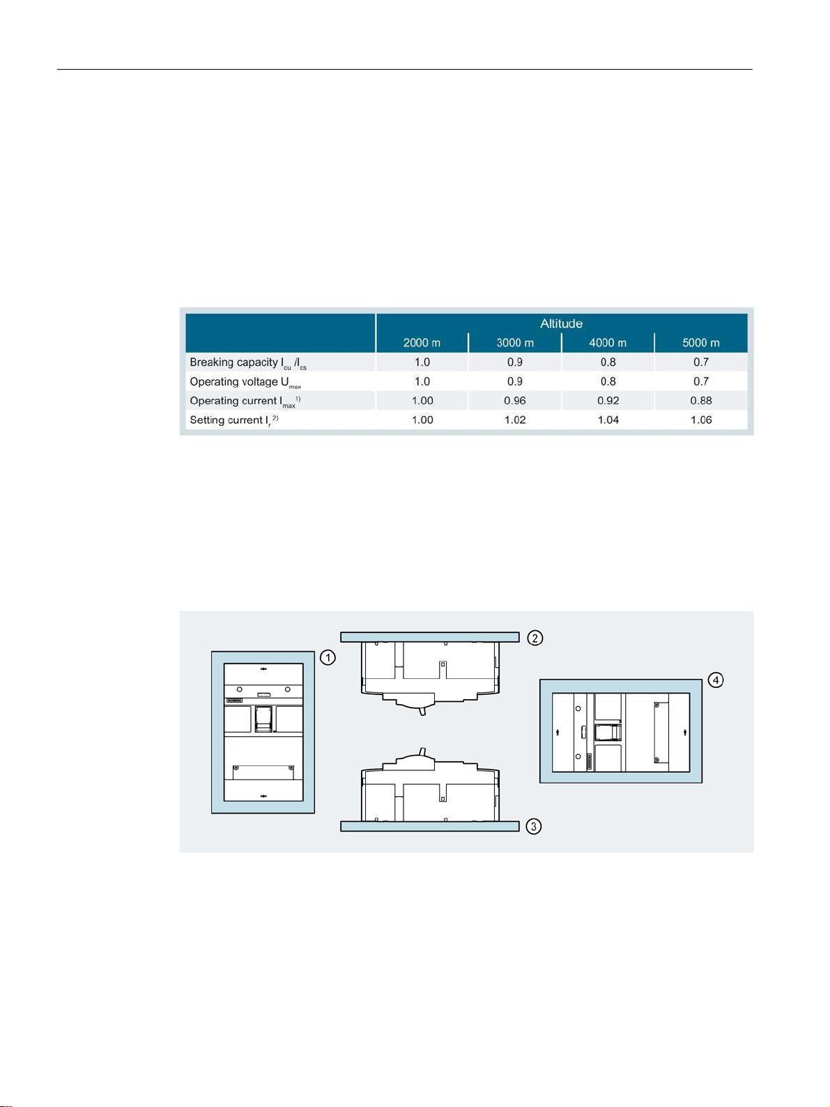
Description
Installation altitudes
2.5.5
Permissible mounting positions
①
②
③
④
2.5 Standards and guidelines
When 3VA1 and 3VA2 molded case circuit breakers are used at up to 2000 m above sea
level, the rated data will not change.
An installation altitude above 2000 m can lead to higher temperatures at the switching
devices. The lower density of air can significantly reduce heat dissipation,
making it necessary to decrease rated operational voltage, the rated uninterrupted current
and the short-circuit values.
Refer to the table below for the calculation factor for determining the key values:
1)
At maximum ambient temperature +50 °C
2)
Thermal-magnetic trip units only
The permissible mounting positions for 3VA molded case circuit breakers are illustrated
below:
Vertical wall mounting
Ceiling mounting
Floor mounting
Laterally rotated wall mounting
3VA molded case circuit breakers
62 Manual, 04/2015, A5E03603177010-02
Page 63
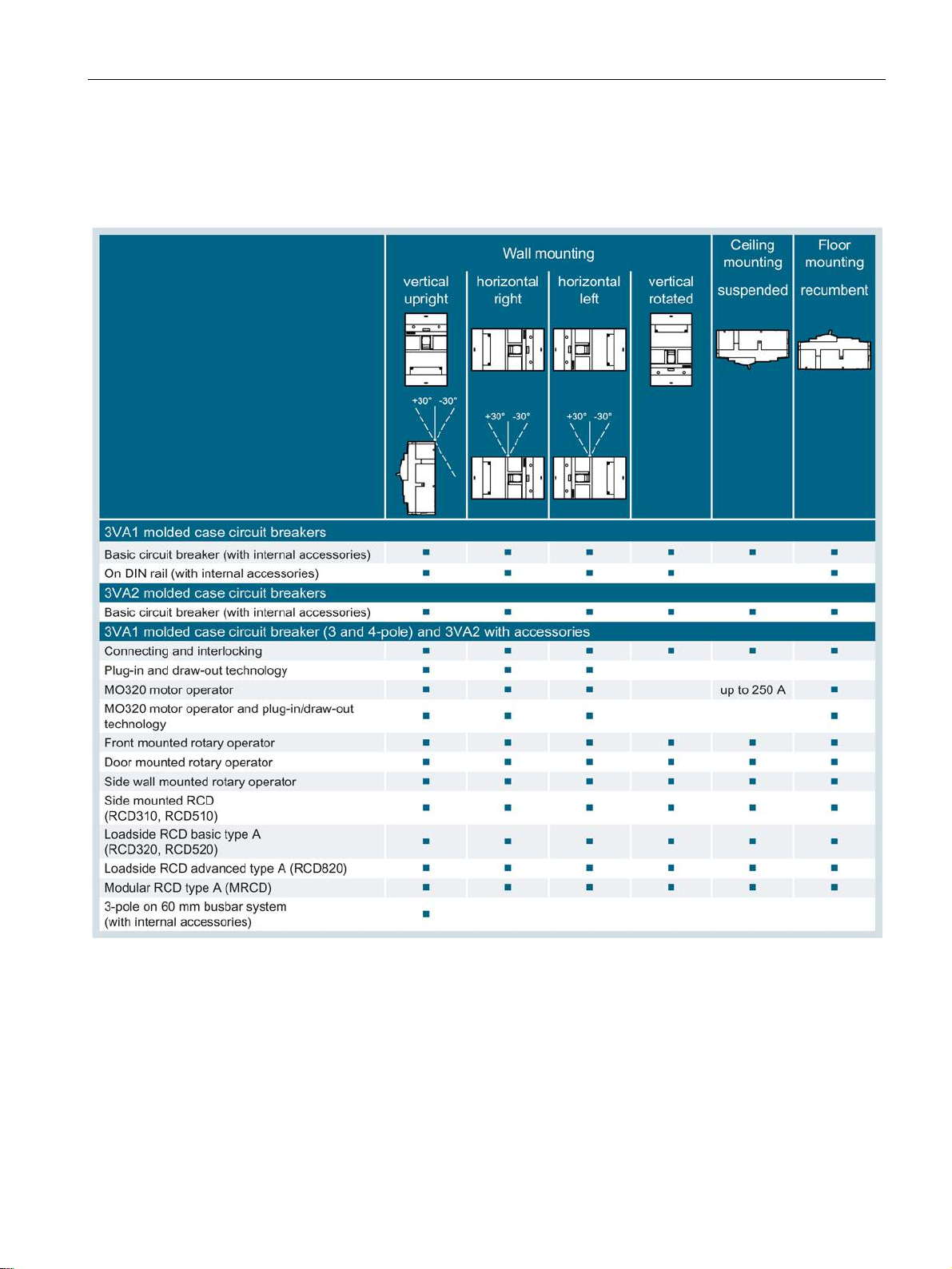
Description
Further mounting positions, and mounting positions with accessories
2.5 Standards and guidelines
The following table shows the possible variations on the mounting positions, as well as
mounting positions with accessories:
3VA molded case circuit breakers
Manual, 04/2015, A5E03603177010-02
63
Page 64
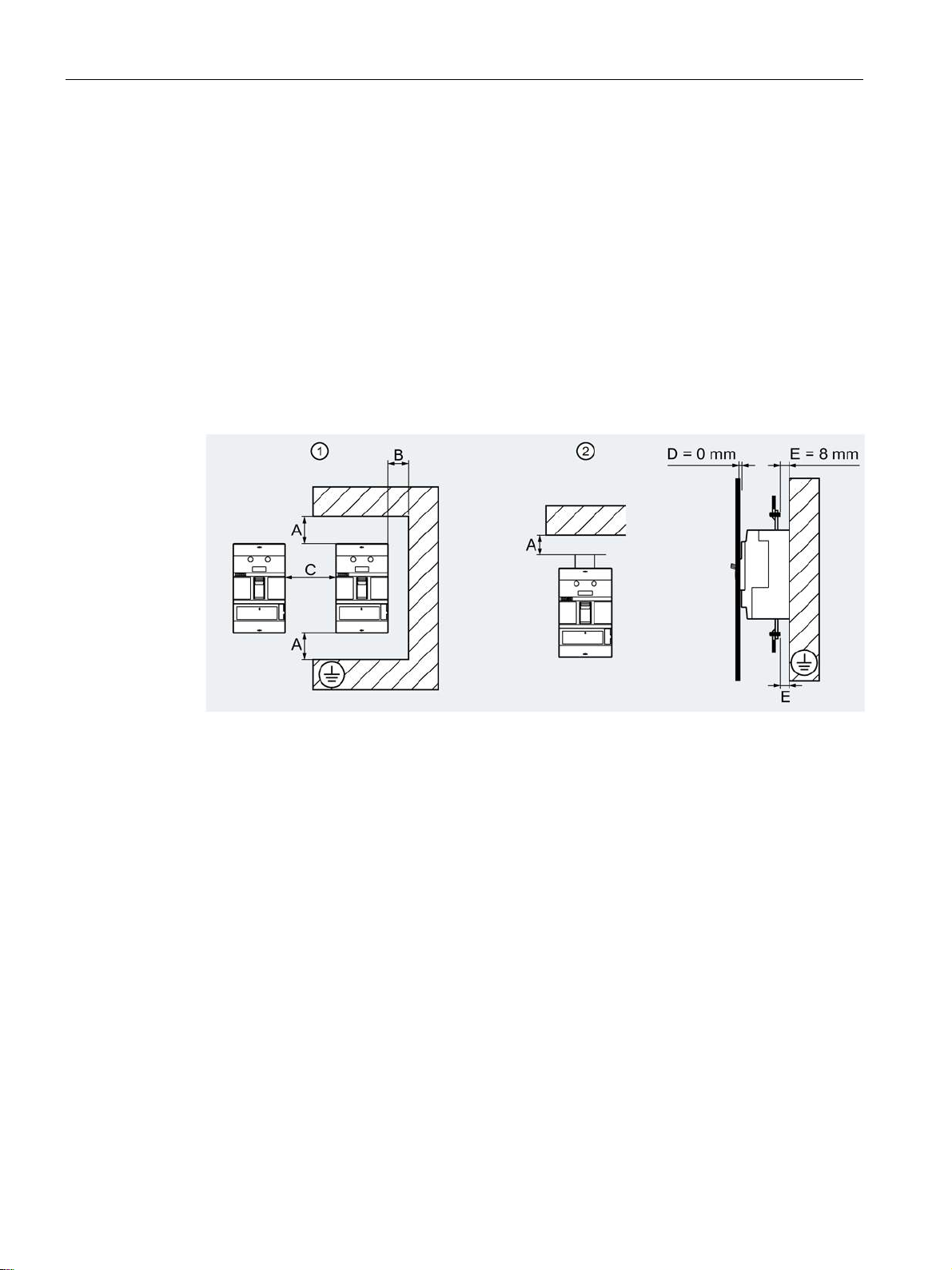
Description
2.5.6
Safety clearances
①
②
Minimum clearance between molded case circuit breaker and side walls left / right (uninsulated
earance between two horizontally installed molded case circuit breakers, see tables
2.5 Standards and guidelines
During a short-circuit interruption, high temperatures, ionized gases and high pressures
occur in and above the arcing chambers of the molded case circuit breaker.
Safety clearances are required to:
● allow pressure distribution
● prevent fire or damage caused by any diffused ionized gases
● prevent a flashover to grounded parts
● prevent arcing or short-circuit currents to live sections.
The following safety clearances apply to 3VA molded case circuit breakers:
Molded case circuit breaker without accessories or with short terminal cover
Molded case circuit breaker with accessories, e.g. phase barrier or long terminal cover
A Minimum clearance between molded case circuit breaker and current paths (uninsulated and
grounded metal), see tables below
B
and grounded metal), see tables below
C Minimum cl
below;
applicable to fixed-mounted and plug-in versions (see chapter
(Page 201))
D Minimum clearance between molded case circuit breaker and control cabinet door
E Minimum clearance between live parts of connection system and grounded mounting plate
Plug-in and draw-out technology
3VA molded case circuit breakers
64 Manual, 04/2015, A5E03603177010-02
Page 65
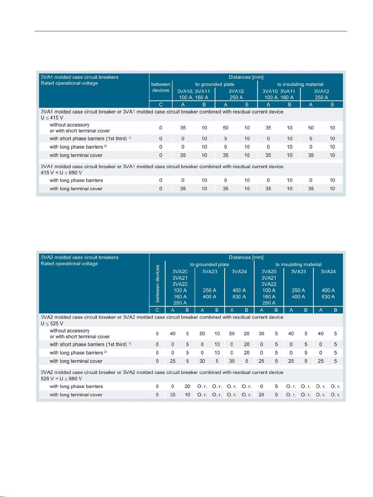
Description
connection bars broadened
2.5 Standards and guidelines
Minimum clearance for 3VA1 molded case circuit breakers:
1)
Can be used for connection methods: box terminal, screw-type terminal, internal circular conductor terminal, and
rear terminals
2)
Can be used for connection methods: circular conductor terminal large, front connection bars extended, and front
Minimum clearance for 3VA2 molded case circuit breakers:
1)
Can be used for connection methods: box terminal, screw-type terminal, internal circular conductor terminal, and
rear terminals
2)
Can be used for connection methods: circular conductor terminal large, front connection bars extended, and front
connection bars broadened
O. r. On request
3VA molded case circuit breakers
Manual, 04/2015, A5E03603177010-02
65
Page 66

Description
Note
NOTICE
Damage to the molded case circuit breaker and the system
2.5 Standards and guidelines
In addition to the clearances stated above, any insulating equipment that might be required
must also be considered, see chapter Insulating equipment (Page 191).
It must be ensured that the cable or busbar connection does not reduce the air insulation
clearance.
Accessory components can increase the width or height of the molded case circuit breaker.
In this case the minimum clearances apply from the corresponding sides of the overall
molded case circuit breaker/accessory combination.
Depending on the application, larger minimum clearances may be necessary.
Please observe the specifications regarding air and creepage distances in the applicable
overriding guidelines (e.g. IEC 61439).
3VA molded case circuit breakers
66 Manual, 04/2015, A5E03603177010-02
Page 67
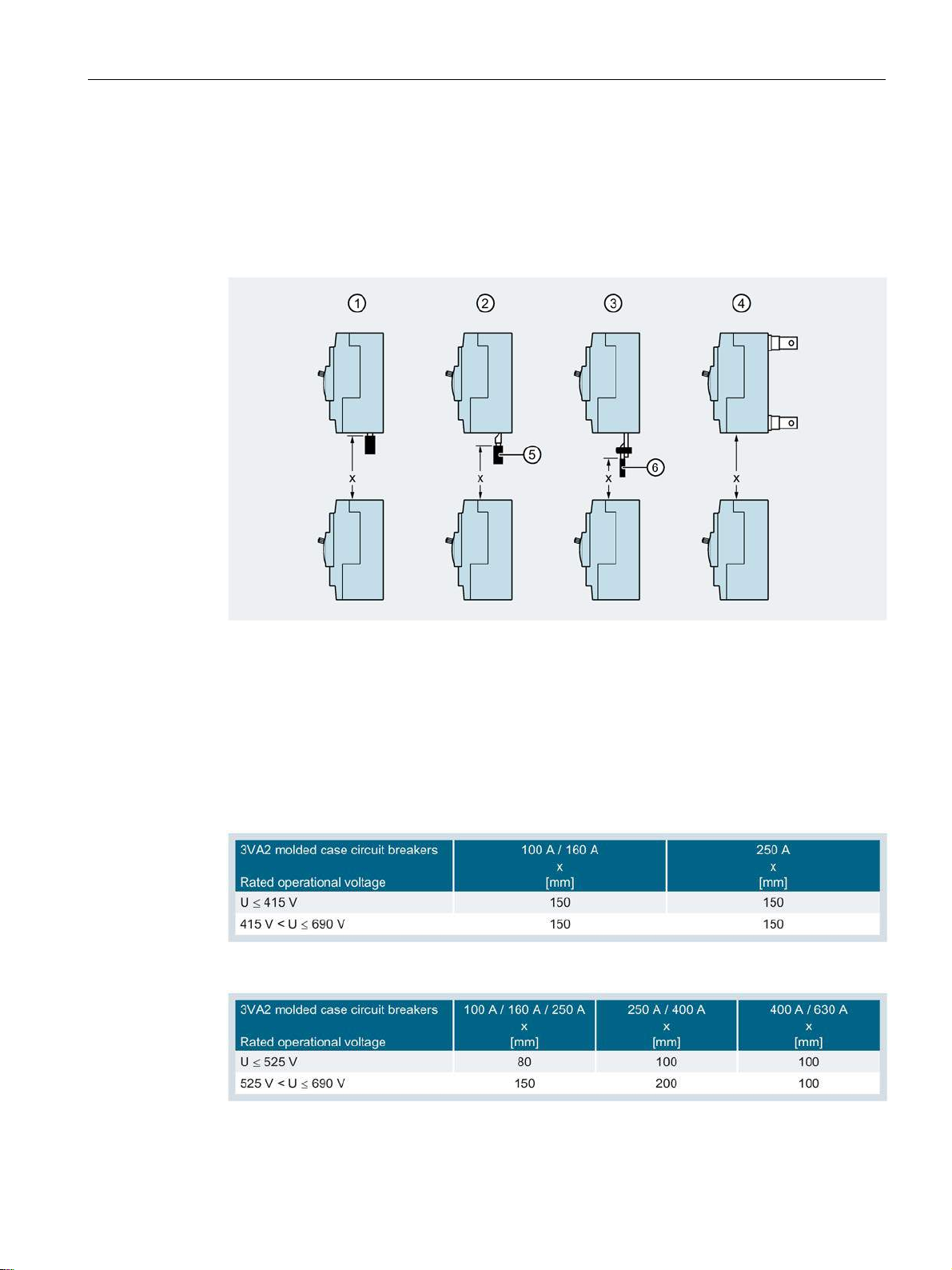
Description
Safety clearances between molded case circuit breakers
①
②
③
④
⑤
⑥
2.5 Standards and guidelines
No minimum clearance needs to be observed between the molded case circuit breakers on
the longitudinal sides (see table above).
The following safety clearances apply to molded case circuit breakers installed directly on
top of each other:
x See tables below for minimum clearance
Front connection with cable, direct
Front connection with cable lug
Front connection with flat busbar
Rear connection with plug-in base or busbar terminals
Insulation of cable
Insulation of busbar
Minimum clearance for 3VA1 molded case circuit breakers:
Minimum clearance for 3VA2 molded case circuit breakers:
3VA molded case circuit breakers
Manual, 04/2015, A5E03603177010-02
67
Page 68
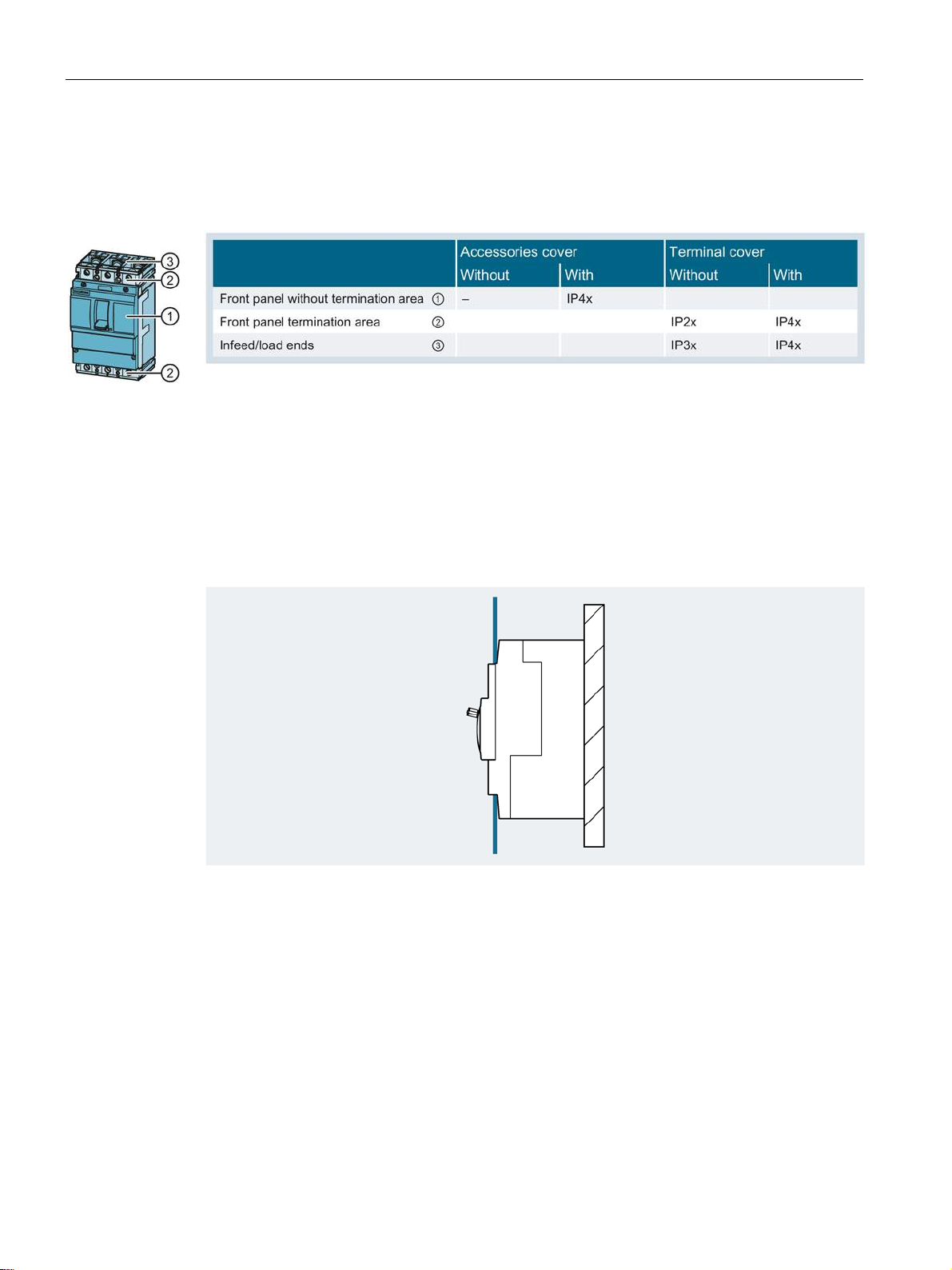
Description
2.5.7
Degrees of protection
2.5.8
Environmental protection
2.5 Standards and guidelines
3VA molded case circuit breakers comply with the following degrees of protection as defined
by IEC 60529 and IEC 60947-1, Appendix C:
Degree of protection IP40 is achieved when a 3VA molded case circuit breaker is installed in
a switchboard with a door cutout including release (see below). The units can be upgraded
to comply with higher degrees of protection up to IP65 by installation of the following
components:
● Door mounted rotary operator
● Side wall mounted rotary operator
Maximum door cutout IP40:
Handle and release are freely accessible, the control cabinet door closes flush with the
molded case circuit breaker.
The 3VA1 and 3VA2 molded case circuit breakers meet the specifications of the European
Environment Guideline 2002 / 95 / EU RoHS directive (Restriction of the use of certain
hazardous substances in electrical and electronic equipment). The development and
production processes have been devised to have the lowest possible environmental impact.
3VA molded case circuit breakers
68 Manual, 04/2015, A5E03603177010-02
Page 69

Description
2.6
Protection system
2.6 Protection system
This chapter contains an overview of the protection system of 3VA molded case circuit
breakers.
The topics discussed in this chapter are listed below:
● Description of functions
● Overload protection (L)
● Short-time delayed short-circuit protection (S)
● Instantaneous short-circuit protection (I)
● Ground-fault protection (G)
● Neutral conductor protection (N)
● ZSI - Zone Selective Interlocking
● Guide to setting the tripping characteristic
3VA molded case circuit breakers
Manual, 04/2015, A5E03603177010-02
69
Page 70
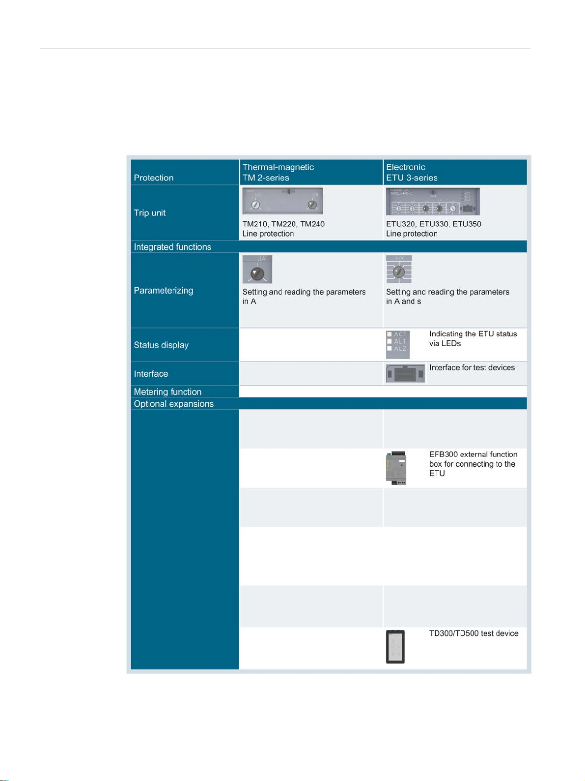
Description
2.6.1
Description of functions
2.6 Protection system
The protection function performed by the molded case circuit breaker in the power
distribution network is defined by the choice of trip unit. There are two different types of trip
unit, i.e. thermal-magnetic (TMTU) and electronic (ETU):
3VA molded case circuit breakers
70 Manual, 04/2015, A5E03603177010-02
Page 71
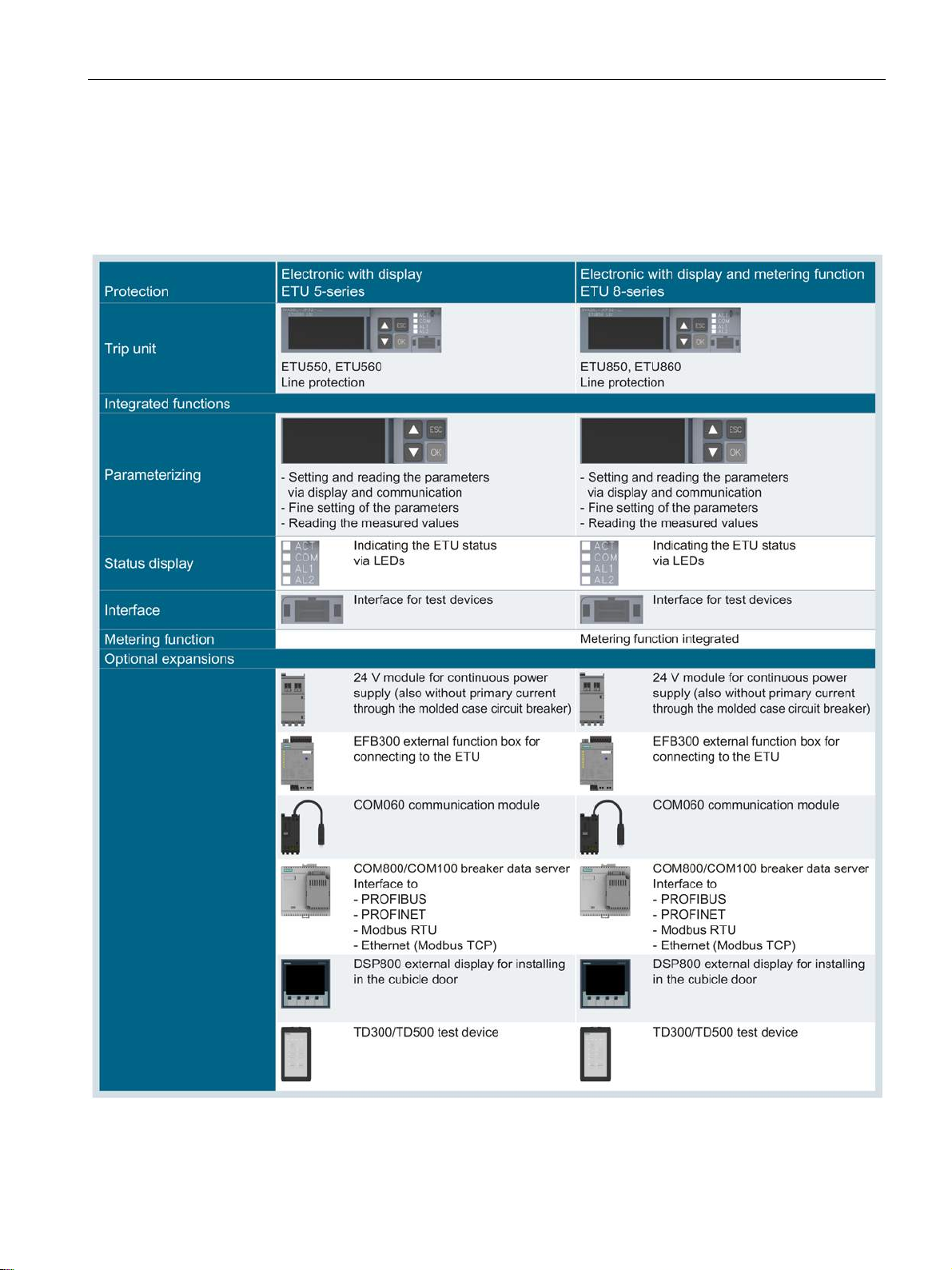
Description
2.6 Protection system
3VA molded case circuit breakers
Manual, 04/2015, A5E03603177010-02
71
Page 72

Description
2.6.2
Characteristic curves
Tripping characteristics for thermal-magnetic trip units
Tripping characteristics for electronic trip units
2.6 Protection system
To design a low-voltage switchboard in accordance with the valid rules, the system planner
needs to dimension the protection settings of the molded case circuit breakers.
The settings selected for the trip unit of a molded case circuit breaker depend on the type of
equipment to be protected, e.g. switchboard and applications.
Tripping characteristics up to a tripping time of ≥ 1 ms are represented graphically. In order
to ease the coordination of different protection devices, the current is specified as a multiple
of the current setting value and the time is specified in seconds.
Characteristics are displayed graphically in the double-log coordinate system (cf.
IEC 60947-2, paragraph 4.7.4 and IEC 60269-1). The current : time ratio is 2 : 1.
Characteristics are displayed graphically in the double-log coordinate system (cf.
IEC 60269-1). The current : time ratio is 1 : 1.
3VA molded case circuit breakers
72 Manual, 04/2015, A5E03603177010-02
Page 73
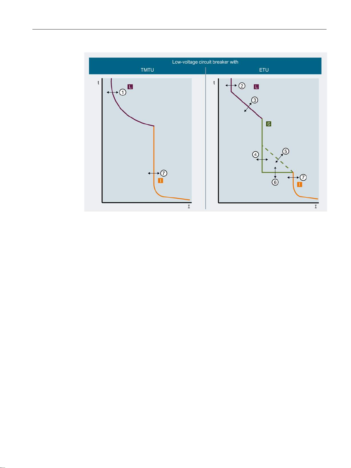
Description
①
⑥
②
⑦
③
④
⑤
2.6 Protection system
Response threshold of the long-time delayed
protection, thermal
Response threshold of the long-time delayed
protection
Delay of the long-time delayed protection L Overload range
Response threshold of the short-time delayed
protection
I2t characteristic ON/OFF of the short-time
delayed protection
Delay of the short-time delayed protection
Response threshold of the instantaneous
protection
S Short-time delayed short-circuit current
range
I Instantaneous short-circuit current range
3VA molded case circuit breakers
Manual, 04/2015, A5E03603177010-02
73
Page 74
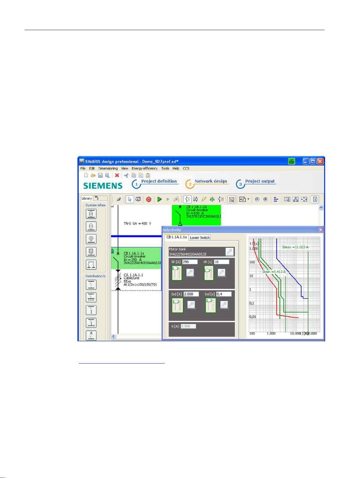
Description
2.6.3
Guide to setting the tripping characteristic
Supplementary conditions
SIMARIS design
2.6 Protection system
The settings selected for the trip unit of a molded case circuit breaker depend on the
technical environment (e.g. switchboard and applications) and the type of equipment to be
protected. The task of calculating and dimensioning the protection settings in accordance
with the valid rules is the responsibility of the system planner.
The Siemens SIMARIS design software tool is a fast, simple and reliable tool for calculating
and dimensioning networks in accordance with the valid rules:
For further information about SIMARIS design, please visit:
(http://www.siemens.com/simaris
3VA molded case circuit breakers
74 Manual, 04/2015, A5E03603177010-02
)
Page 75
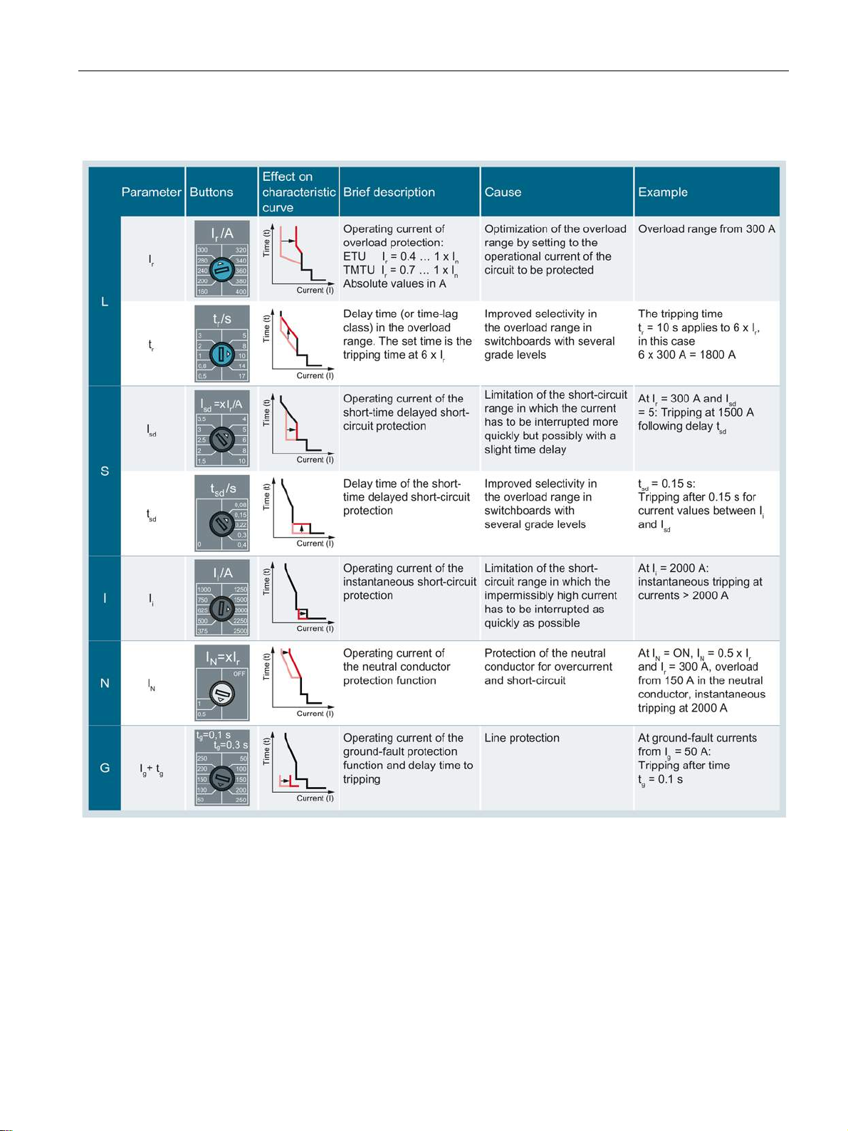
Description
Basic rules for setting different trip parameters
Setting the parameters for trip units ETU 5-series and 8-series
2.6 Protection system
ETU 5-series and 8-series are equipped with an LCD.
Parameter settings can be adjusted via this LCD, values are input by means of buttons. The
powerconfig software can also be used to input parameter settings. The TD500 test device
and the COM800/COM100 breaker data server combined with the COM060 communication
module can be used as the software interface.
3VA molded case circuit breakers
Manual, 04/2015, A5E03603177010-02
75
Page 76
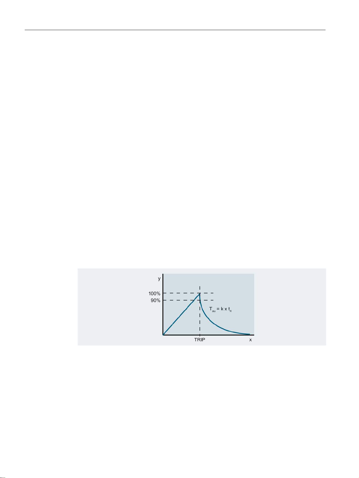
Description
2.6.4
Overload protection (L)
Thermal image
Thermal image activated (ON)
Thermal image deactivated (OFF)
2.6 Protection system
The ID letter for overload protection is L (stands for "Long-time delay").
The trip unit is inverse-time delayed and exhibits the following characteristics depending on
the trip unit type:
● Bimetal characteristic with thermal-magnetic trip units
2
t characteristic with electronic trip units
● I
The letters I
refer to the current setting value, and tr to the associated time delay.
r
The time delay with the device-specific reference point defines the current-dependent curve
shape of the setpoint characteristic. With 3VA molded case circuit breakers, this trip unit
reference point corresponds to 6 times the current setting value I
. The following
r
mathematical equation determines the remaining curve of the setpoint characteristic:
2
I
t = constant
The electronic trip units feature a thermal image function that can be deactivated on some
electronic trip units.
If the thermal image is activated, the previous thermal history is taken into account. After
tripping, the thermal memories of the phases are set to a value corresponding to 85 % of the
thermal equivalent of the warmest phase. This setting allows reclosure of the contacts of the
molded case circuit breaker. This is followed by a cool-down period according to an
exponential function with a time constant T
au
(τ).
The thermal image for ETU 5-series and 8-series can be deactivated to allow use of the
TD500 test device for characteristic curve tests. The thermal image must remain activated in
normal operation. When the image is deactivated, the thermal prehistory of the circuit
breaker, the cables/busbars, other components of the lower-level power distribution system
or an end consumer is ignored.
It is the responsibility of the commissioning engineer/operator to provide additional thermal
overload protection for the lower-level power distribution system while the thermal image is
deactivated.
3VA molded case circuit breakers
76 Manual, 04/2015, A5E03603177010-02
Page 77

Description
2.6.5
Short-time delayed short-circuit protection (S)
2.6.6
Instantaneous short-circuit protection (I)
2.6.7
Ground-fault protection (G)
2.6 Protection system
The ID letter for short-time delayed short-circuit protection is "S" (stands for "Short-time
delay"). The S function of the trip unit can be used to implement time-selective short-circuit
tripping in low-voltage networks in which multiple molded case circuit breakers are installed
in series.
The short-time delayed short-circuit protection function protects phases L1 to L3 and the
neutral conductor. The protection function responds if the current in at least one phase
exceeds the set tripping current I
The S release operates according to a characteristic with a current-dependent curve I
for the set delay period tsd.
sd
2
t. The
electronic trip units ETU 5-series and 8-series can be optionally switched over to a currentindependent tripping characteristic.
The ID letter for instantaneous short-circuit protection is "I" (stands for "Instantaneous").
This short-circuit protection function protects phases L1 to L3. The instantaneous shortcircuit protection function responds if the instantaneous value equal to the rms of the current
in at least one phase exceeds the instantaneous tripping current I
.
i
The ID letter for ground-fault protection is "G" (ground fault).
The G protection detects residual currents between phases and grounded, electrically
conductive parts. The ground-fault protection function responds if the ground fault current
exceeds the set tripping current I
for the set delay period tg.
g
Ground-fault protection can be implemented as a current-independent and a currentdependent function (I
2
t).
On 4-pole molded case circuit breakers and 3-pole molded case circuit breakers with
external current transformer for N conductor, the G protection calculates the vector sum of
the currents of the three phases and the neutral conductor. The G release trips the breaker
or an alarm is issued via the communication system if the rms value of this vector sum
exceeds the set trip value I
for the duration of the set delay tg.
g
3VA molded case circuit breakers
Manual, 04/2015, A5E03603177010-02
77
Page 78

Description
2.6.8
Neutral conductor protection (N)
Note
Neutral conductor protection
Neutral conductor protection and 3VA2 molded case circuit breakers
2.6 Protection system
The ID letter for neutral conductor protection is "N".
The neutral conductor protection system protects the neutral conductor against overloads
and short circuits.
The letters I
A neutral conductor with full cross sectional area (distributed neutral conductor of the same
size as the phases) is normally protected by the phase protection system and does not
require separate protection.
Neutral conductor protection must be implemented in accordance with the standards valid in
the country of installation. Possible reasons for implementing neutral conductor overload
protection are:
● The neutral conductor has a smaller cross section than the phase conductors.
● Harmonic levels in the installation are expected to be higher than normal.
● A large number of loads, or predominantly single-phase loads, will be connected.
● The neutral conductor will be isolated for functional reasons, e.g. because there are
several voltage sources.
● The neutral conductor will be isolated for safety reasons, e.g. because work is in progress
on disconnected units
refer to the current setting value; the associated setting time is identical to tr.
N
The following versions of 3VA2 molded case circuit breaker have neutral conductor
protection:
● All 3-pole versions with external current transformer for N conductor
● All 4-pole versions
Oversized neutral conductor protection can be implemented in combination with the
electronic trip units ETU 5-series and 8-series. This might be necessary to provide protection
against third-order harmonics and multiples thereof.
3VA molded case circuit breakers
78 Manual, 04/2015, A5E03603177010-02
Page 79
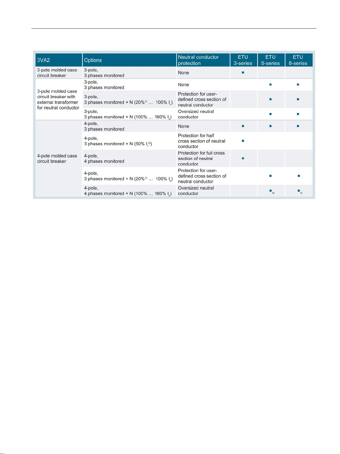
Description
Parameters of the neutral conductor protection function
2.6 Protection system
N Neutral conductor protection
1)
At rated operational currents In ≤ 63 A: IN = 40 % … 100 % In
2)
Applies to In > 63 A
3)
Dependent on circuit breaker size and rated operational current
● Tripping current IN:
Adjustable as a proportion of the current setting (I
● Tripping delay:
Corresponds to the delay setting (t
) for overload protection
r
● Tripping current of the short-time delayed short-circuit protection:
Corresponds to the short-time delayed short-circuit protection (I
● Tripping delay:
Corresponds to the delay setting for short-time delayed short-circuit protection (t
● Instantaneous short-circuit protection:
Corresponds to the tripping current (I
) for overload protection
r
)
sd
) for instantaneous short-circuit protection
i
)
sd
3VA molded case circuit breakers
Manual, 04/2015, A5E03603177010-02
79
Page 80
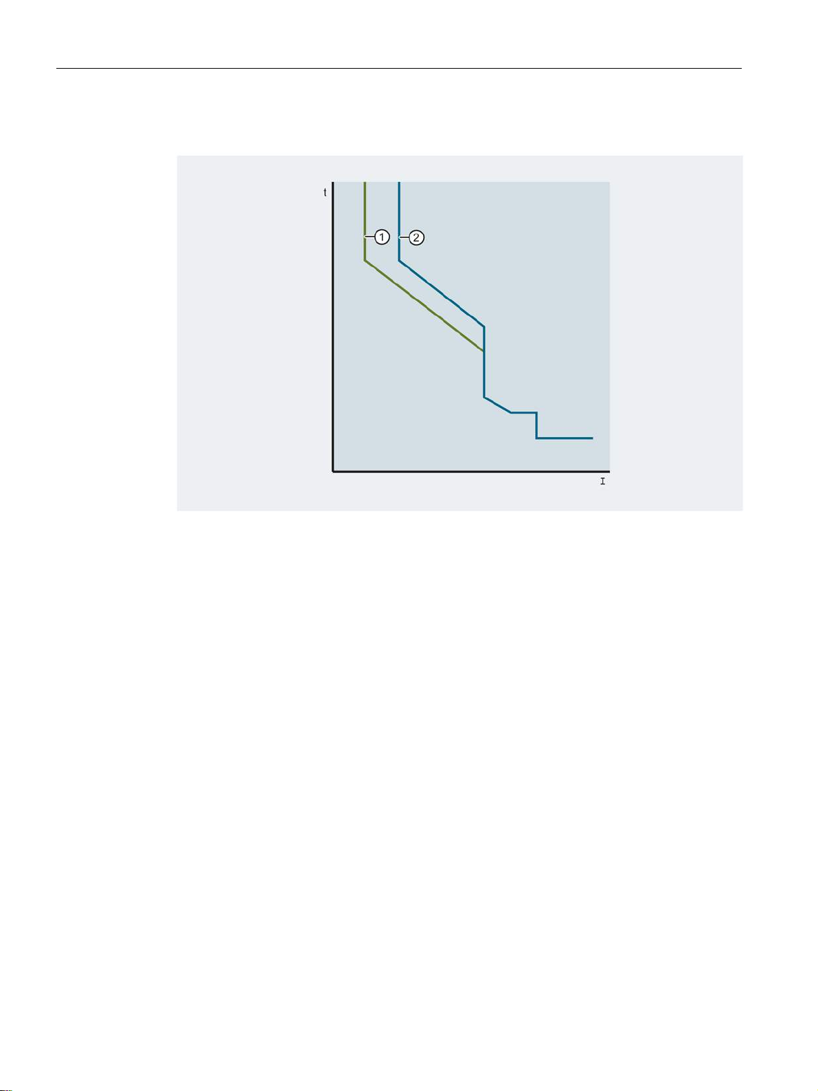
Description
Example of a neutral conductor protection characteristic
①
②
Adjustment of neutral conductor protection settings
2.6 Protection system
Response threshold of the neutral conductor protection
Response threshold of the long-time delayed protection
The tripping current IN can be adjusted:
● for ETU 3-series trip units via setting buttons
● for ETU 5-series and 8-series trip units
– via the buttons on the ETU display
– via a PC using powerconfig
3VA molded case circuit breakers
80 Manual, 04/2015, A5E03603177010-02
Page 81

Description
2.6.9
Zone-selective interlocking ZSI
Note
Downward compatibility
2.6 Protection system
The microprocessor-controlled, zone-selective interlocking function has been developed in
order to control the total breaking time in low-voltage networks with multiple molded case
circuit breakers connected in series.
Regardless of the number of series-connected molded case circuit breakers, all short circuits
in the network can be cleared within a maximum time period of 50 ms.
The ZSI function of 3VA molded case circuit breakers is compatible with the ZSI functions of
Siemens 3VL molded case circuit breakers and 3WL air circuit breakers.
3VA molded case circuit breakers
Manual, 04/2015, A5E03603177010-02
81
Page 82
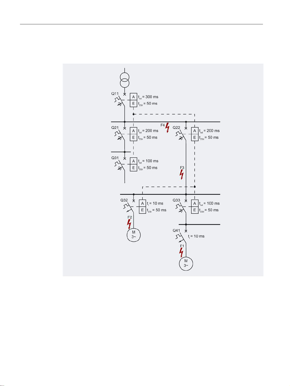
Description
Operating principle
2.6 Protection system
The diagram below demonstrates the operating principle of zone-selective interlocking:
- - - Communication cable t
A Output, transmits the blocking signal t
E Input, receives the blocking signal t
"Virtual" tripping time of I protection
i
Delay time setting of S protection
SD
Delay time of all molded case circuit breakers
ZSI
which detect the short circuit but do not receive
a blocking signal when ZSI is activated
The ZSI function acts on the S and G ranges of the tripping characteristic. Currents within
the I range (instantaneous short circuit) continue to cause instantaneous tripping.
3VA molded case circuit breakers
82 Manual, 04/2015, A5E03603177010-02
Page 83

Description
Fault 1
Fault 2
Fault 3
Fault 4
2.6 Protection system
If the short-circuit current is sufficiently large, the trip units of molded case circuit breakers
Q41, Q33, Q22 and Q11 are activated. Since Q41 clears the fault within t
= 10 ms, none of
i
the other molded case circuit breakers trips even though Q41 has no ZSI and cannot
therefore transmit a blocking signal to Q33.
If the short-circuit current is sufficiently large, the trip units of molded case circuit breakers
Q32, Q22 and Q11 are activated. As a result of the ZSI function, Q32 temporarily blocks Q22
which in turn temporarily blocks Q11. Depending on the magnitude of the short-circuit
current, the fault is cleared either within t
= 10 ms or t
i
= 50 ms.
zsi
Q22 signals short-circuit protection to Q11 with the result that only Q22 trips when delay time
t
= 50 ms expires. Without the ZSI function, the fault would not be cleared until tsd = 200 ms
zsi
had expired.
The short circuit is detected only by Q11. Since Q11 does not receive a blocking signal from
the downstream molded case circuit breakers, it trips after t
function, Q11 would not trip until t
= 300 ms had expired.
sd
= 50 ms. Without the ZSI
zsi
It is especially important to minimize breaking times when short circuits involving very high
short-circuit currents occur.
3VA molded case circuit breakers
Manual, 04/2015, A5E03603177010-02
83
Page 84

Description
2.7
Thermal-magnetic trip unit
2.7.1
Thermal trip unit (L)
2.7.2
Magnetic trip unit with short-circuit protection (I)
2.7 Thermal-magnetic trip unit
A thermal-magnetic trip unit consists of a thermal trip unit for protecting against overload,
and a magnetic trip unit for protecting against short circuits. Both trip units are seriesconnected.
The thermal trip unit consists of a temperature-dependent bimetal that heats up as a result of
the flow of current. This means the trip unit is current-dependent. The temperature rise in the
bimetal strip depends not only on the current magnitude, but also on the ambient
temperature of the molded case circuit breaker. All current values specified for thermalmagnetic trip units of 3VA circuit breakers refer to an ambient temperature of +50 ℃.
The magnetic trip unit with short-circuit protection comprises a yoke mounting through which
a current path runs, and a flap armature that is kept at a distance from the yoke mounting by
a tension spring.
If a short-circuit current flows along the current path, the magnetic field thus generated
causes the flap armature to be moved towards the yoke mounting against the opposite force
of the tension spring. The tripping time is almost current-independent and instantaneous.
The flap armature releases the breaker mechanism and thus opens the switching contacts.
Immediately after tripping, the flap armature is moved back to its starting position by the
restoring force of the tension spring.
3VA molded case circuit breakers
84 Manual, 04/2015, A5E03603177010-02
Page 85
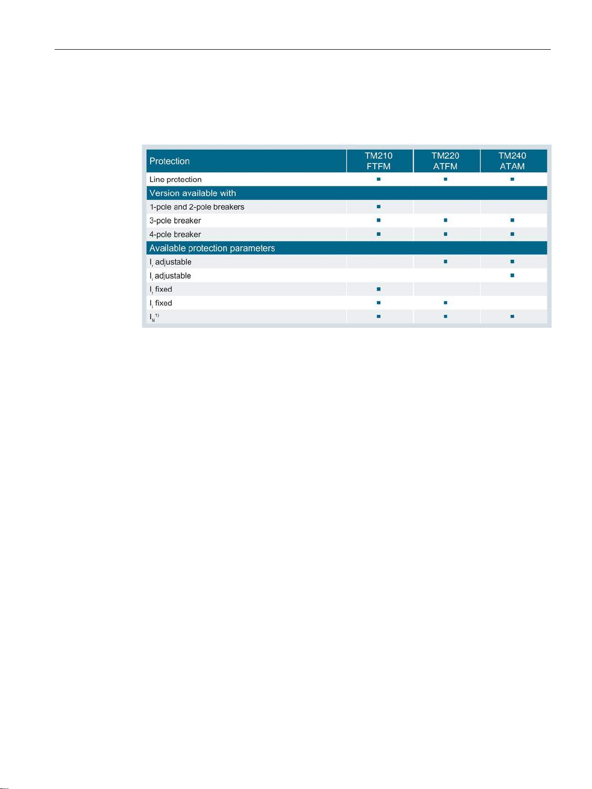
Description
2.7.3
Application cases and trip unit types
2.7 Thermal-magnetic trip unit
The table below illustrates the applications for which different types of thermal-magnetic trip
units can be used:
1)
For 4-pole molded case circuit breakers only, available without protection, 50% (≥ In 100 A) and
100%
3VA molded case circuit breakers
Manual, 04/2015, A5E03603177010-02
85
Page 86
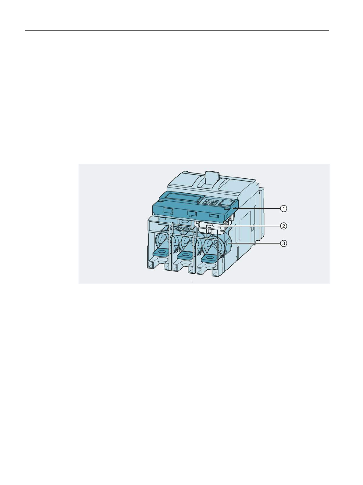
Description
2.8
Electronic trip unit
①
②
③
2.8 Electronic trip unit
An electronic trip unit is based on the following concepts:
● Complete measurement of the current in the phases L1, L2 and L3, with N and currents
to ground optional
● Rogowski coil
– Very precise measurement of the current
– Better ground-fault protection because the vectorial sum is more exact
● Evaluation of the current measurement values and constant comparison with the tripping
limits
● Tripping by means of a maglatch
Electronic Trip Unit (ETU)
Maglatch
Current sensor
3VA molded case circuit breakers
86 Manual, 04/2015, A5E03603177010-02
Page 87
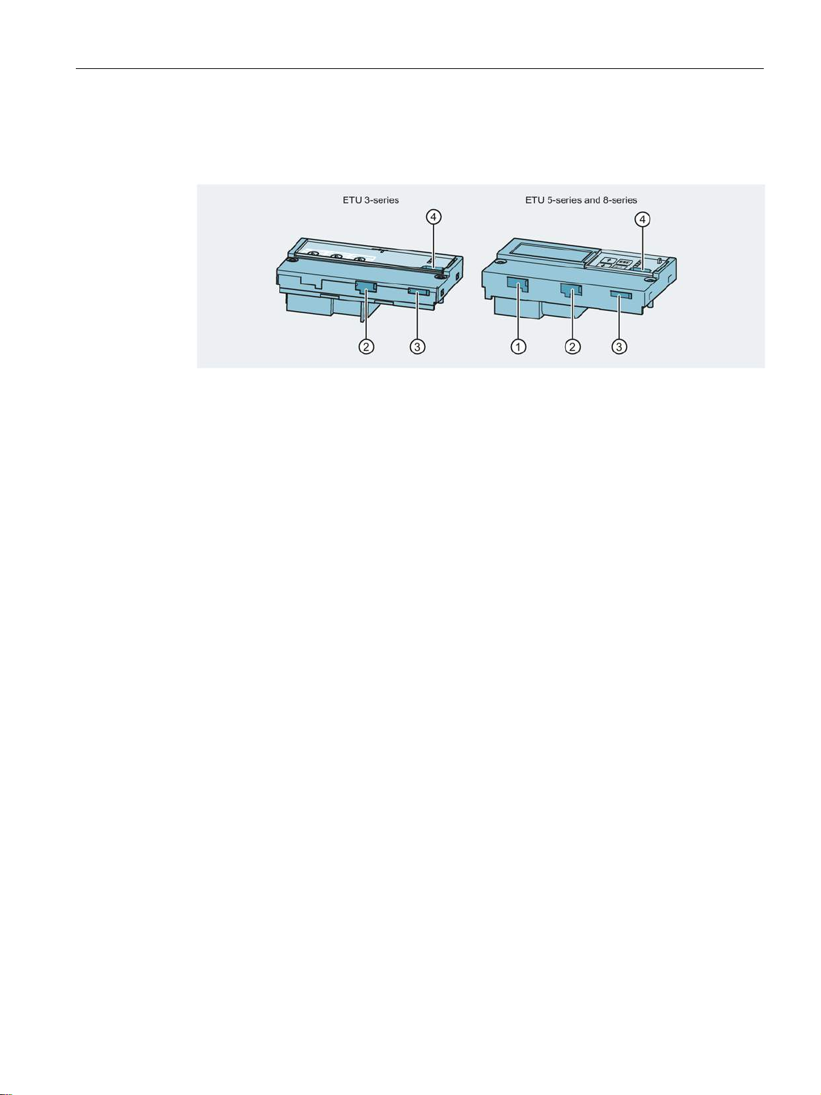
Description
2.8.1
Connections
①
Interface for an external current transformer for N conductor
②
Interface for connection of an EFB300 external function box
③
④
Connection for test devices TD300 and TD500
2.8 Electronic trip unit
The connections on the ETU are illustrated in the diagram below:
Interface for connection of an RCD820 residual current device
3VA molded case circuit breakers
Manual, 04/2015, A5E03603177010-02
87
Page 88
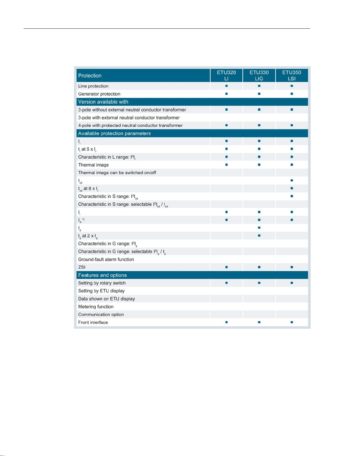
Description
2.8.2
Protection functions
2.8 Electronic trip unit
1)
Available in a version with external current transformer for N conductor or 4-pole breaker
3VA molded case circuit breakers
88 Manual, 04/2015, A5E03603177010-02
Page 89
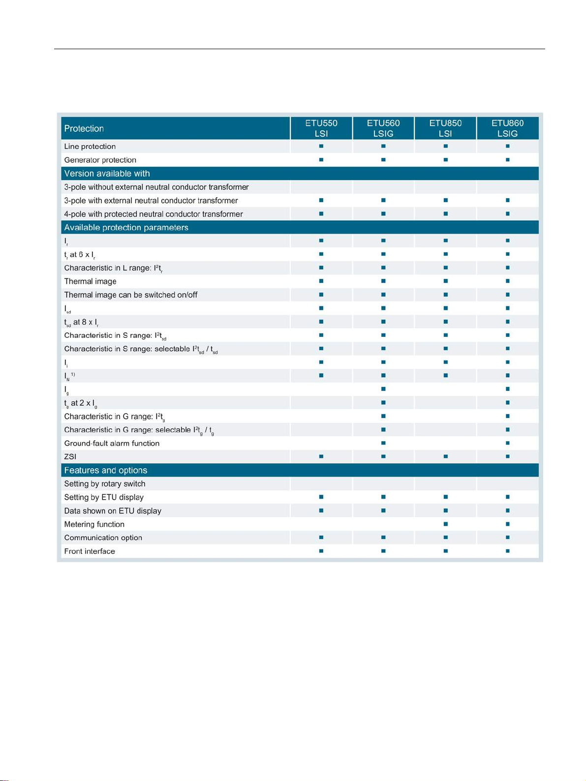
Description
2.8 Electronic trip unit
1)
Available in a version with external current transformer for N conductor or 4-pole breaker
3VA molded case circuit breakers
Manual, 04/2015, A5E03603177010-02
89
Page 90
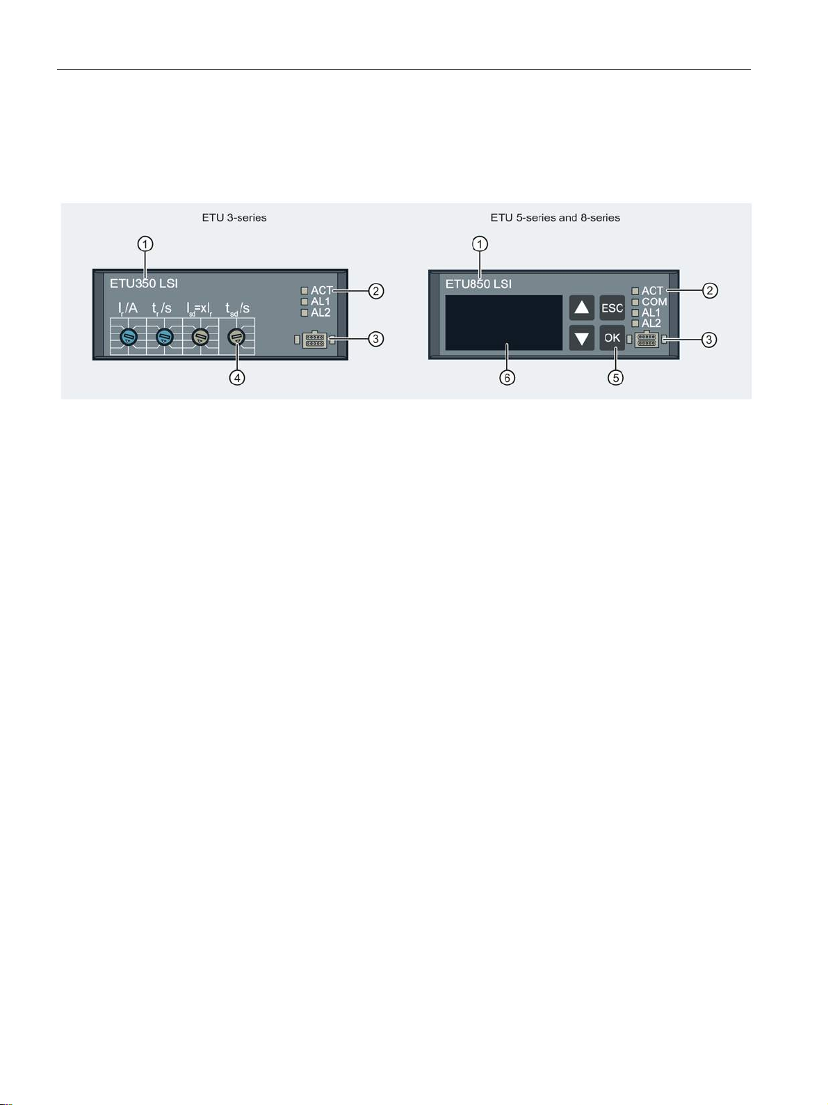
Description
2.8.3
Operator controls
①
③
⑤
②
④
⑥
2.8 Electronic trip unit
Name of the ETU
LED display
The following figure shows the available ETU types of the 3VA2 molded case circuit
breakers. You can decide which ETU to install according to the area of application.
Front interface
Setting buttons
Pushbuttons
LCD
3VA molded case circuit breakers
90 Manual, 04/2015, A5E03603177010-02
Page 91
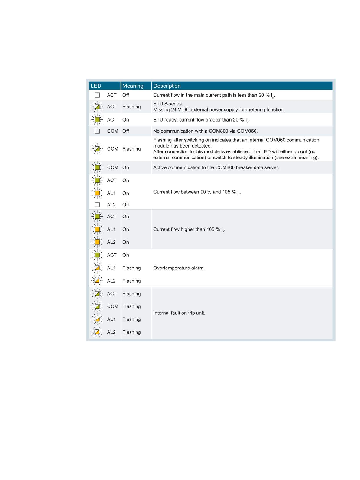
Description
LED displays
2.8 Electronic trip unit
The following table explains what the LED displays mean:
3VA molded case circuit breakers
Manual, 04/2015, A5E03603177010-02
91
Page 92
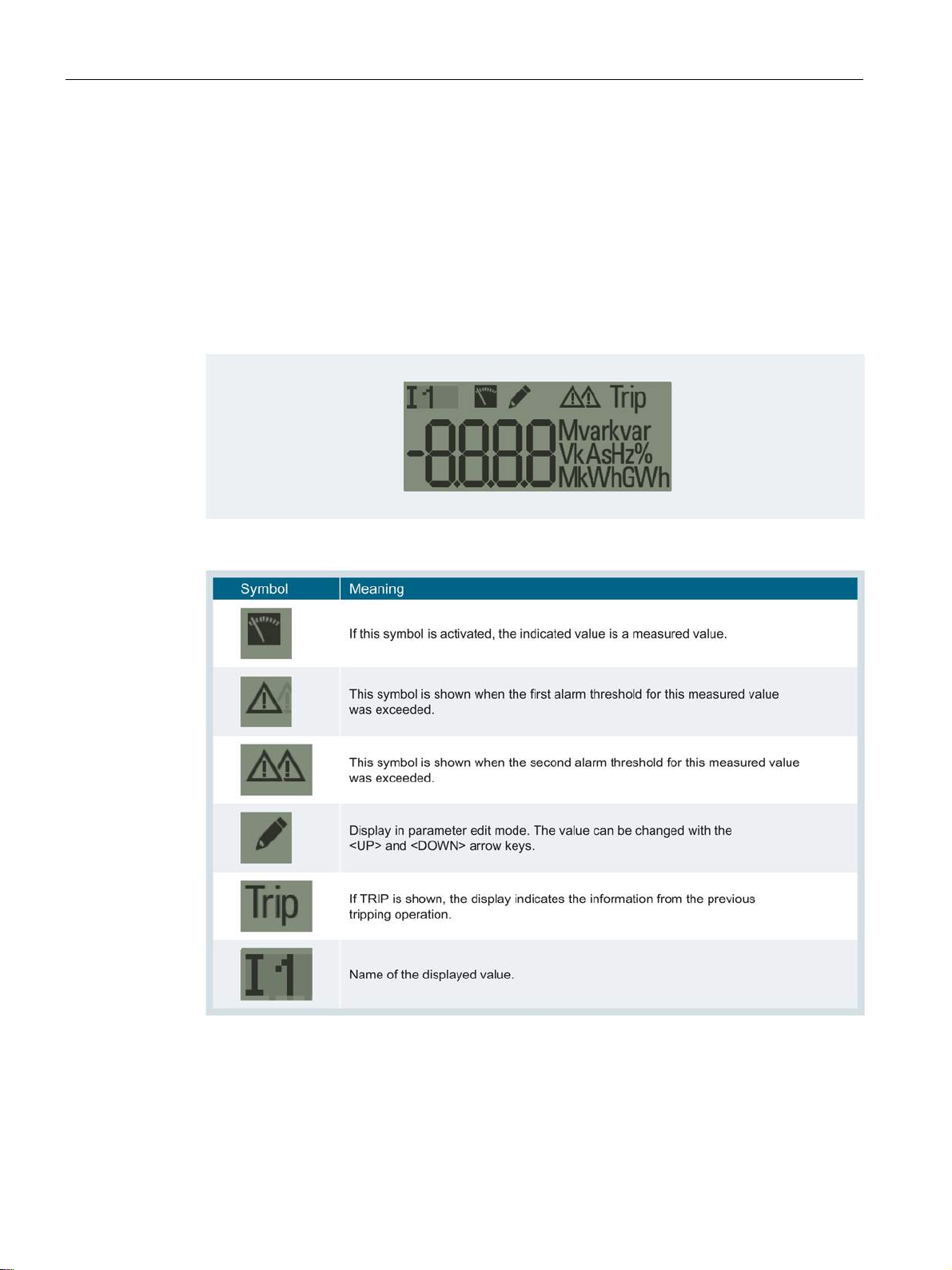
Description
ETU 3-series units
Displays on ETU 5-series and 8-series units
2.8 Electronic trip unit
3-series electronic trip units are equipped with setting buttons. A description of the operating
principle of the setting buttons and operating instructions can be found in chapter Guide to
setting the tripping characteristic (Page 74).
5-series and 8-series electronic trip units have an LCD display. The displayed values are
refreshed once per second.
The following table explains what the symbols in the display mean:
3VA molded case circuit breakers
92 Manual, 04/2015, A5E03603177010-02
Page 93
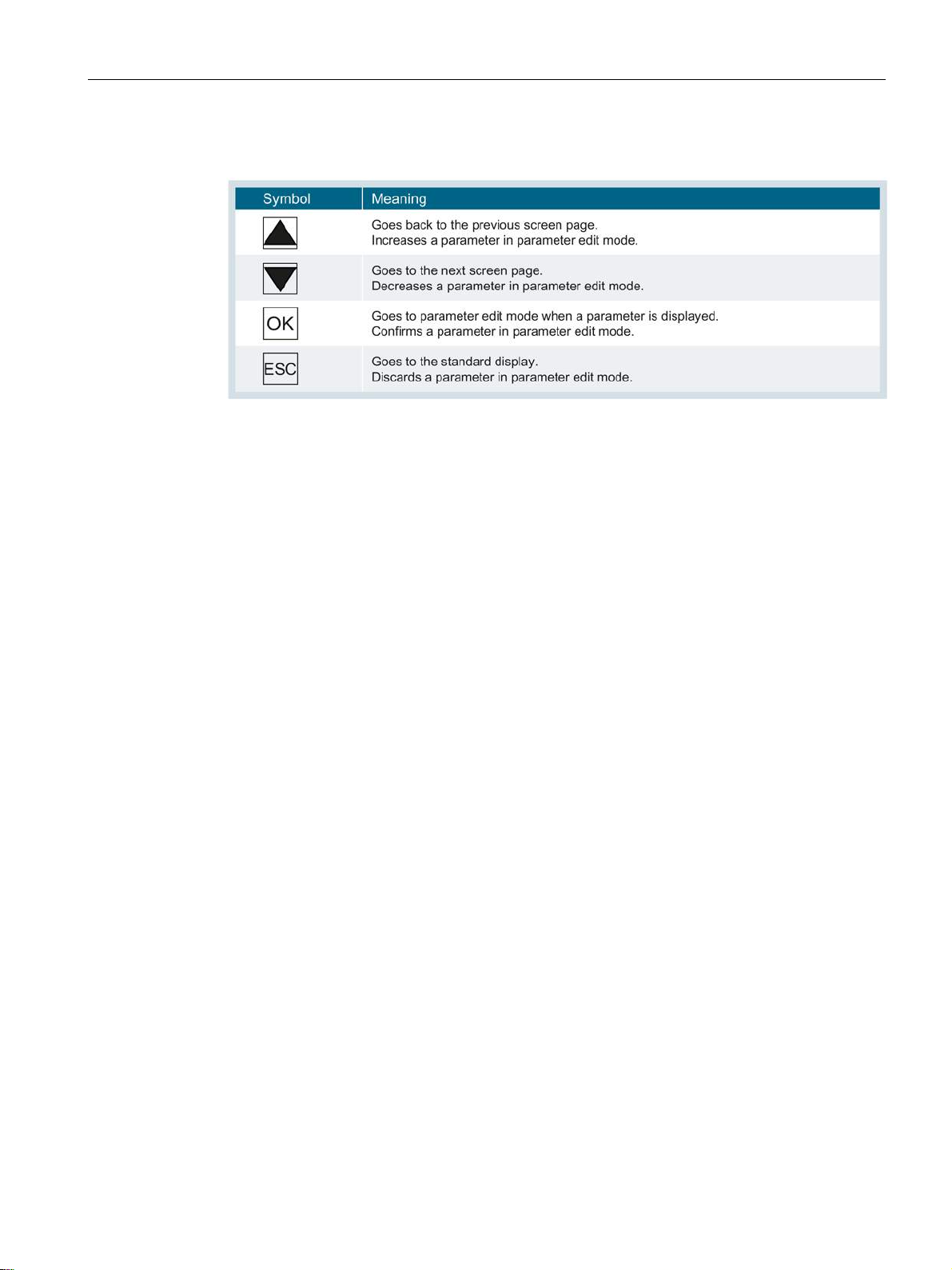
Description
Displays on ETU 5-series and 8-series units
2.8 Electronic trip unit
The following table explains what functions are performed by the buttons next to the display:
The basic structure comprises the following displays:
● Standard display
● Alarm display
● Measured value display
● Parameter display
If no selection is made within an adjustable time period, the standard display will appear.
3VA molded case circuit breakers
Manual, 04/2015, A5E03603177010-02
93
Page 94
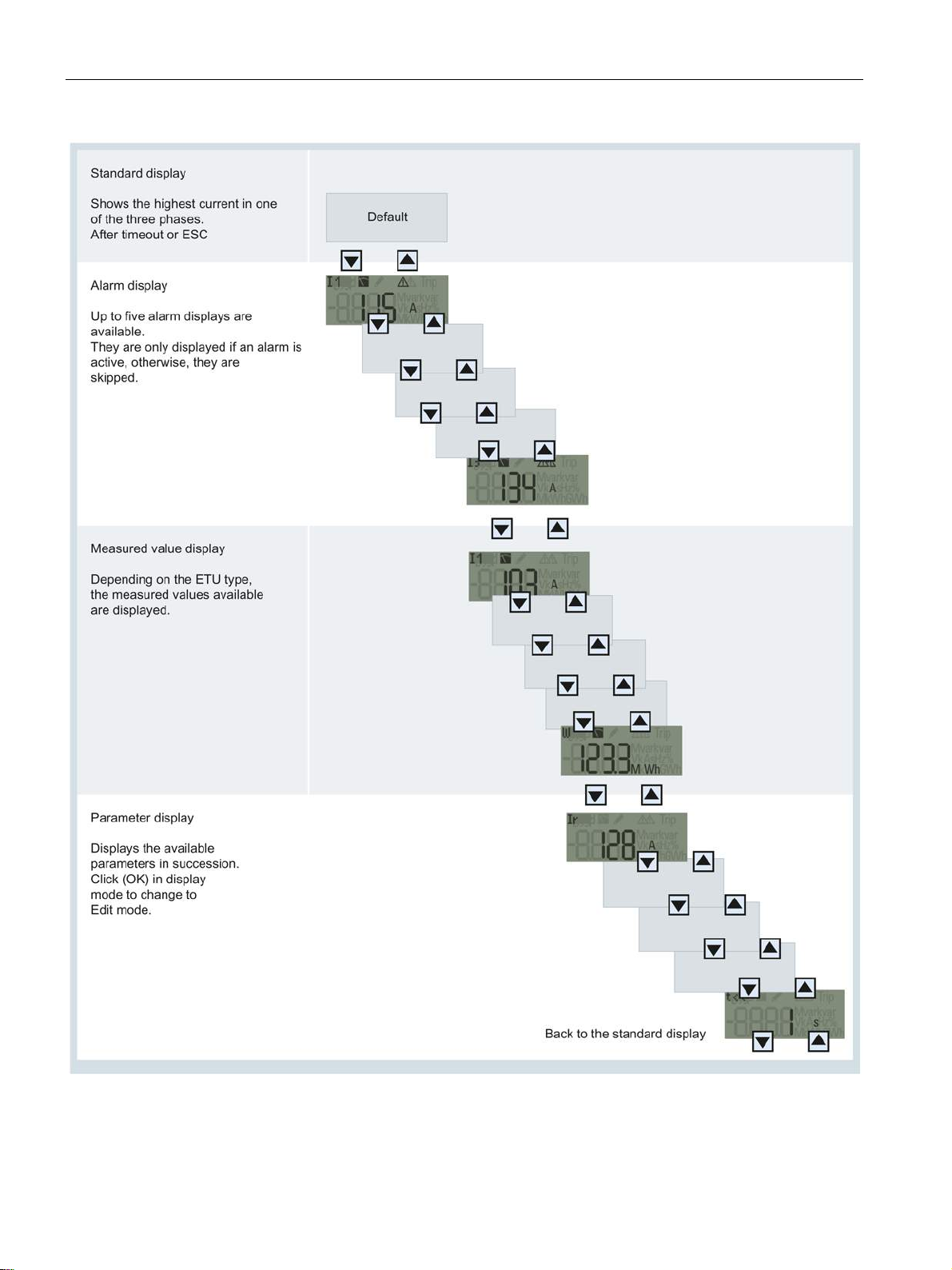
Description
2.8 Electronic trip unit
3VA molded case circuit breakers
94 Manual, 04/2015, A5E03603177010-02
Page 95
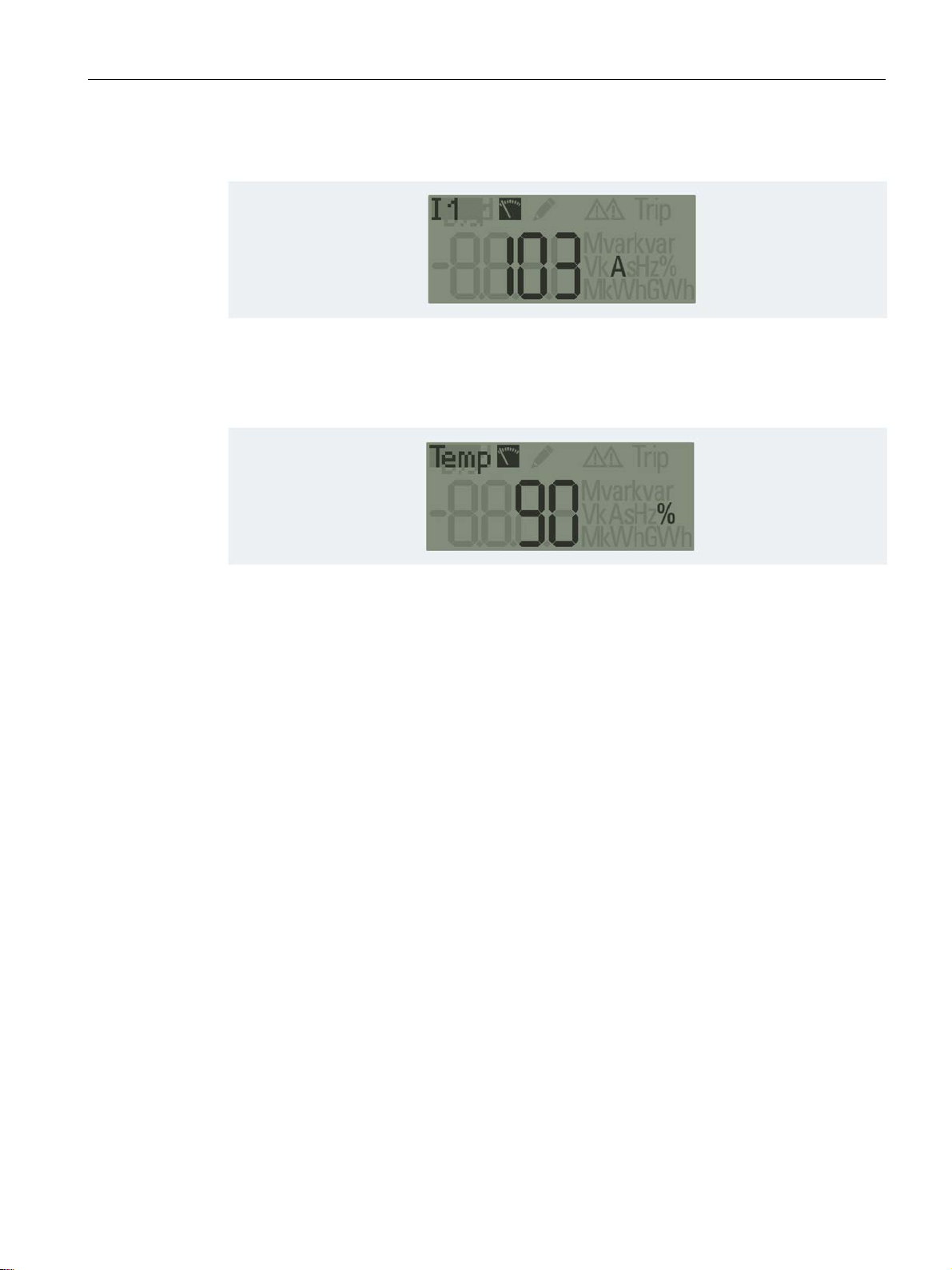
Description
Standard display
Alarm display
2.8 Electronic trip unit
Active alarms are displayed consecutively in screens AV1 … AV5. If no alarms are active,
these screens are concealed.
3VA molded case circuit breakers
Manual, 04/2015, A5E03603177010-02
95
Page 96
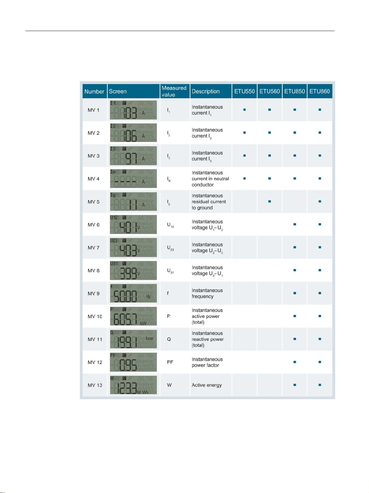
Description
Measured value display
2.8 Electronic trip unit
The table below explains the measured value display:
3VA molded case circuit breakers
96 Manual, 04/2015, A5E03603177010-02
Page 97
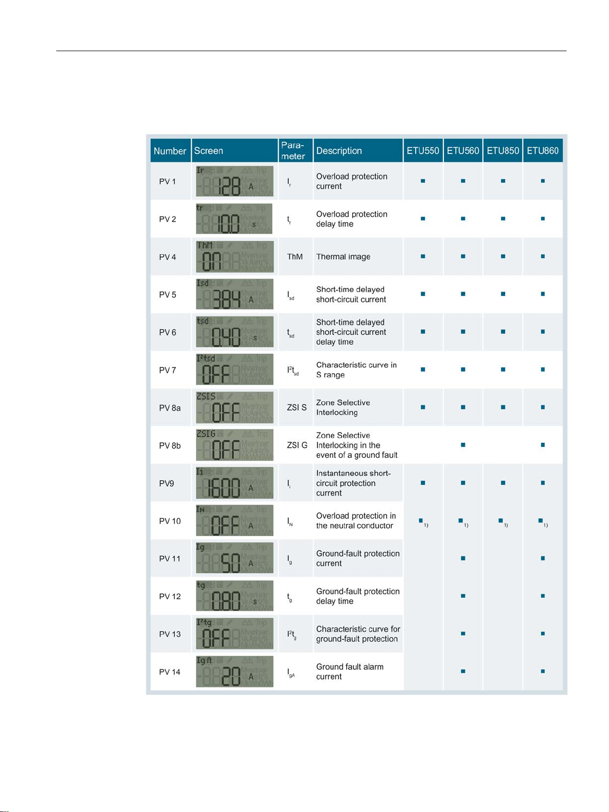
Description
Parameter display
2.8 Electronic trip unit
The table below explains the parameter display:
3VA molded case circuit breakers
Manual, 04/2015, A5E03603177010-02
97
Page 98
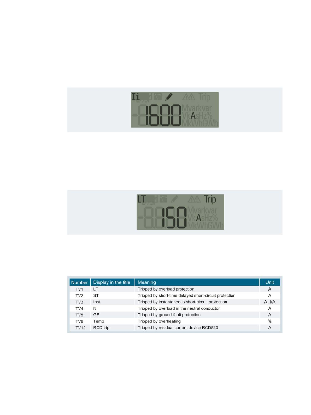
Description
Setting and changing parameters
"Tripped" display
2.8 Electronic trip unit
1. Use the arrow keys to navigate to the correct display.
2. Press the <OK> button.
→ Edit mode is active. Activation is confirmed by display of "pencil" symbol.
3. Use the arrow keys to adjust the parameter setting.
4. Confirm the setting with the <OK> button, or cancel the operation with <ESC>.
→ The setting is accepted with <OK>. The parameter display now appears.
After the ETU has initiated a trip, the "Tripped" display automatically appears:
This screen can be identified by the word "Trip" which is displayed in the top, right-hand
corner. The displayed current value shows the current at the moment of tripping.
Press <ESC> to exit the display.
The additional information contained in the "Tripped" display is explained in the table below:
3VA molded case circuit breakers
98 Manual, 04/2015, A5E03603177010-02
Page 99
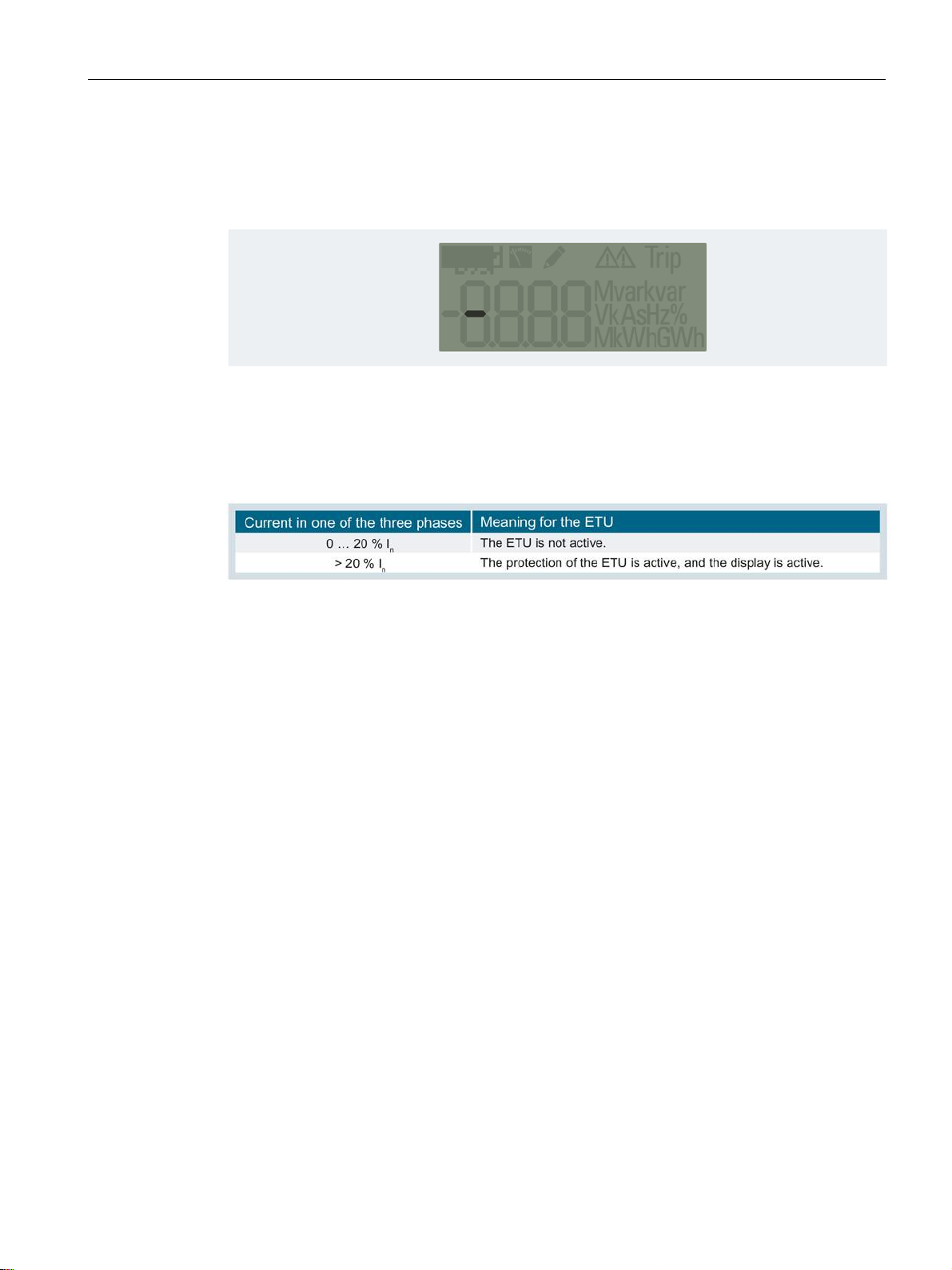
Description
Diagnostics display
Activation limits
2.8 Electronic trip unit
When a TD500 test device is connected, you can use it to initiate a test. The following
screen appears when a TD500 is connected. The bar flashes at a frequency of 0.5 Hz.
The bar travels from left to right while testing is in progress. The test ends with a trip.
The table below shows the activation limits for the ETUs:
3VA molded case circuit breakers
Manual, 04/2015, A5E03603177010-02
99
Page 100
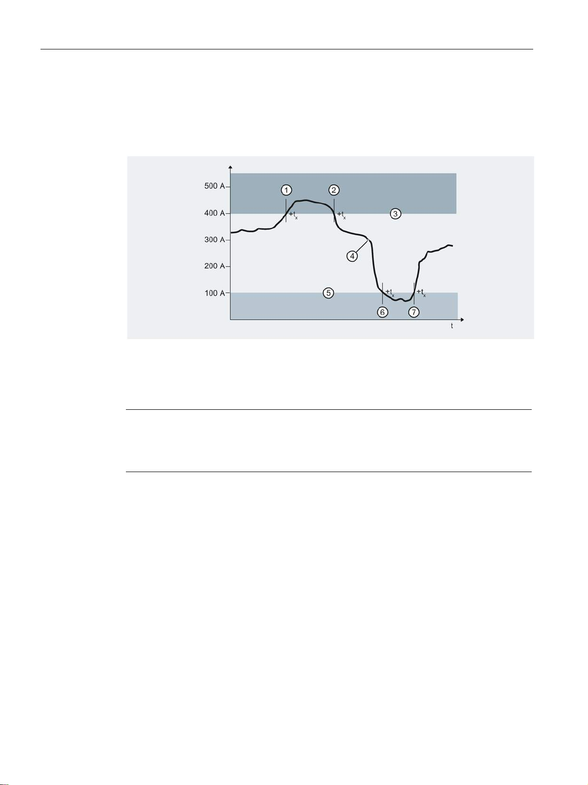
Description
2.8.4
Load acceptance and load shedding - load management
①
⑤
②
⑥
③
⑦
④
Note
No trip
2.8 Electronic trip unit
3VA molded case circuit breakers equipped with an ETU 3-series or higher series provide
two current thresholds for the purpose of implementing a local load management function.
Load shedding is the upper threshold, and load acceptance the lower threshold.
Incoming alarm "load shedding"
Outgoing alarm "load shedding"
Parameter load shedding 400 A
Current in one phase
Parameter load acceptance 100 A
Incoming alarm "load acceptance"
Outgoing alarm "load acceptance"
Tripping is never initiated as a result of the current value crossing the upper or lower
thresholds.
If the current in one phase exceeds the parameter setting for "load shedding", an incoming
alarm "load shedding" is generated. Only when the current in all three phases drops below
this threshold is an outgoing alarm "load shedding" generated.
The incoming and outgoing alarms can be output via an optional EFB module and
transferred via the communication link.
The opposite applies for the load acceptance threshold. If the current in all three phases
drops below the parameter setting, an incoming alarm "load acceptance" is generated. If
only one of the three currents exceeds the parameter setting, an outgoing alarm "load
acceptance" is generated.
To prevent these alarms being generated by brief current peaks and troughs, they can be
delayed by the time t
from 1 s to 15 s.
x
3VA molded case circuit breakers
100 Manual, 04/2015, A5E03603177010-02
 Loading...