

Page 1
SIRIUS Innovations Supplement 2011
6
Combination Starters &
Starters for Group Installation
SIRIUS 3RA2 Motor Starters
6/2
General data
3RA21 Direct-On-Line Starters
6/13 AC 50/60 Hz 110/120 V
6/15 24 V DC
3RA22 Reversing Starters
6/17 AC 50/60 Hz 110/120 V
6/19 24 V DC
6/21
Accessories
6/31
3RV29 Infeed System for
Motor Starters
For Operation in the Control Cabinet
SIRIUS 3RA6 Compact Starters
6/32
General data
3RA61, 3RA62 Compact Starters
6/40
3RA61 direct-on-line starters
6/41
3RA62 reversing starters
3RA64, 3RA65 Compact Starters for
IO-Link
6/42
3RA64 direct-on-line starters
6/43
3RA65 reversing starters
6/44
Accessories
6/50
Add-On Modules for AS-Interface
6/52
Infeed Systems for 3RA6
Technical Information
can be found at
www.siemens.com/industrial-controls/
support
under Product List:
- Technical specifications
under Entry List:
- Updates
- Download
- FAQ
- Manuals
- Characteristics
- Certificates
SIRIUS Motor Starters
© Siemens AG 2011
Page 2

Combination Starters & Starters for Group Installation
SIRIUS 3RA2 Motor Starters
General data
6/2
SIRIUS Innovations Supplement 2011
6
■
Overview
3RA2 motor starters
The 3RA2 fuseless motor starters consist of the 3RV2 motor
starter protector and the 3RT2 electromechanical contactor. The
devices are electrically and mechanically connected using preassembled assembly kits (link modules, wiring kits and standard
mounting rail or
busbar adapters).
Around 500 preassembled 3RA2 combinations of these innovative 3RT2 controls and 3RV2 protection equipment can be
ordered for direct-on-line and reversing starting of standard induction motors up to 32 A (approx. 20 HP/460 V).
In the 3RA2 motor starter, the 3RV2 motor starter protector is
responsible for overload and short-circuit protection. Back-up
protective devices, such as melting fuses or limiters, are superfluous here, as the motor starter protector is capable of withstanding short-circuits up to 65 kA at 480 V and 30 kA at 600 V.
See the the actual SCCR ratings by device listed on the selection
pages of this chapter.
The 3RT2 contactor is particularly suitable for extremely
complex switching tasks requiring the greatest endurance.
The 3RA2 motor starters are available with setting ranges from
0.14 to 32 A in sizes S00 and S0:
The size of the 3RA2 motor starters is based on the size of the
contactor:
1)
The combination of an S00 motor starter protector with an S0 contactor is
possible only for screw connection versions.
Operating conditions
3RA2 motor starters are climate-proof. They are intended for use
in enclosed rooms in which no severe operating conditions
(such as dust, caustic vapors, hazardous gases) prevail. Suitable covers must be provided for installation in dusty and damp
locations.
Tripping times
All 3RA2 motor starters described here are designed for normal
starting, in other words for overload tripping times of less than
10 s (CLASS 10). At rated-load operating temperature the tripping times are shorter, depending on the particular equipment
and the setting range. The exact values can be derived from the
tripping characteristics of the motor starter protectors.
Connection methods
For all 3RA2 starters up to 32 A, spring-type connection is avail-
able as well as screw connection. To connect two devices with
spring-type connection there are plug-in connection modules for
sizes S00 and S0 which enable very quick mounting of the starters and a vibration-resistant assembly.
To connect a motor starter protector with screw connection to a
contactor with spring-type connection there are special hybrid
connection modules for S00 and S0.
While starters can be assembled with either spring-type or
screw connection, the pre-assembled versions offered in this
chapter are with screw terminals only. For spring-type versions,
simply order the components listed on the spring-type terminal
pages and assemble these starters quickly and efficiently without the use of any tools.
Size Width Max. rated current
I
n max
For induction motors
up to
mm A HP
S00 45 16 10
S0 45 32 20
Size of 3RA2 S00 S0
Size of 3RV2 motor starter protector S00 S001), S0
Size of 3RT2 contactor S00 S0
Screw terminals
Spring-type terminals
These terminals are indicated in the corresponding
tables by the symbols shown on orange
backgrounds.
© Siemens AG 2011
Page 3

Combination Starters & Starters for Group Installation
SIRIUS 3RA2 Motor Starters
General data
6/3
SIRIUS Innovations Supplement 2011
6
3RA2 complete units
The 3RA2 fuseless motor starters can be ordered as preassembled complete units for direct-on-line starting (3RA21) or for
reversing duty (3RA22) with screw connection.
Control supply voltages of AC 50/60 Hz 110/120 V and 24 V DC
are available to choose from.
A distinction is also drawn between whether the starter is
mounted on a 35 mm standard mounting rail, on a flat surface
using screws, or on a 60 mm busbar system.
Accessories
As the 3RA2 fuseless motor starters are constructed from 3RV2
motor starter protectors and 3RT2 contactors, the same accessories - such as auxiliary switches, undervoltage releases or
door-coupling rotary operating mechanisms - can be used for
the 3RA2 fuseless motor starters as for these motor starter protectors and contactors.
In particular, certain accessories have been optimized for the
fuseless motor starters. They include the top-connected, transverse auxiliary switch on the motor starter protector, which is
available with 1 CO contact or 1 NO contact + 1 NC contact.
Special auxiliary switch blocks that can be snapped on from
below are available for the contactor. These two accessories
enable the fuseless motor starters to be wired simply without
having to route cables through the device.
Incoming energy supply
On the whole four different infeed possibilities are available (see
"3RV29 Infeed System for Motor Starters" on page 6/31)
.
Customer assembly of fuseless motor starters
While the preassembled 3RA2 can be ordered up to 32 A, combinations in customer assembly without link modules are also
possible up to 40 A (approx. 25 HP/460 V).
Thanks to the SIRIUS modular system, the standard devices can
be optimally combined in terms of both technical specifications
and dimensions.
The fuseless motor starters can also be assembled easily by the
customer. It is simply necessary to assemble the standard 3RV2
motor starter protector, the 3RT2 contactor and the appropriate
assembly kit.
For single devices and assembly kits see "Selection and ordering data" for 3RA21 direct-on-line starters and 3RA22 reversing
starters.
For assembly kits for direct-on-line starting or reversing duty for
mounting on standard mounting rails or busbars see "Selection
and ordering data" for "Accessories".
For reversing starters size S0 it is imperative to use a standard
mounting rail adapter in order to ensure the necessary mechanical strength. A standard mounting rail adapter is not necessary
if a busbar adapter is used.
The 3RA1 fuseless motor starters can be used for the fuseless
motor starters between 32 A and 100 A.
The SENTRON 3VL circuit breakers and the SIRIUS 3RT contactors are available for rated currents >100 A.
Special equipment for customer assembly can be ordered if
other rated control supply voltages are required. Assembly kits
can be used to facilitate assembly.
Customers can also assemble tested combinations of motor
starter protectors with solid-state controls (soft starters, solidstate contactors) and motor starters with additional monitoring
and control devices (3RR monitoring relays, SIMOCODE 3UF).
For the electrical and mechanical connection of protection
equipment and controls there are preassambled assembly kits
(link modules, wiring kits and standard mounting rail or busbar
adapters).
The following types of configuration are possible:
• Direct-on-line/reversing starting (see preassembled 3RA2
combinations)
• Wye-delta starting (only customer assembly with link module)
• Solid-state/soft starting (only customer assembly with link
module)
© Siemens AG 2011
Page 4

Combination Starters & Starters for Group Installation
SIRIUS 3RA2 Motor Starters
General data
6/4
SIRIUS Innovations Supplement 2011
6
Communications integration using IO-Link
Motor starters can also be assembled with IO-Link for connec-
tion to the higher-level control system. For each starter this
requires a communication-capable contactor onto which a
3RA27 11 function module is plugged (various versions for
direct-on-line, reversing and wye-delta starts). The design of the
SIRIUS motor starters permits a group of up to 4 SIRIUS controls
to be conveniently connected through a standardized IO-Link to
a control system, reducing wiring time considerably compared
to the conventional parallel wiring method. The electrical connection is made using only a single cable with three conductors.
The function modules perform not only the communication (contactor operation and feedback, ready signal) but also the electrical interlocking (for reversing and wye-delta starters) and the
timing relay function (wye-delta reversing time).
Communication information and control supply voltages are
passed on through ribbon cables so that the complete control
current wiring on the starter is no longer needed.
The monitoring and maintenance of a plant is made considerably easier by transmitting diverse diagnostics data from the
function modules (e. g. missing main and auxiliary voltage, local
disconnection…) through IO-Link to the higher-level control system. Also, starters equipped for IO-Link can be conveniently
controlled from the control cabinet door using the optional operator panel.
More information:
• For IO-Link see Chapter 2 "Industrial Communication"
• For 3RA27 function modules see Chapter 3 "Controls –
Contactors and Contactor Assemblies" --> "Function
Modules".
Communications integration through AS-Interface
Connection of the motor starters to the higher-level control sys-
tem is possible not only through IO-Link but also through
AS-Interface. The AS-Interface connection is recommended
wherever motor starters are used in distributed applications.
This solution also requires a communication-capable contactor
and a corresponding 3RA27 12 function module (various versions for direct-on-line, reversing and wye-delta starts). The
devices are implemented in A/B technology, making it easy to
connect up to 62 starters to an AS-i master (regardless of
whether they are direct-on-line, reversing or wye-delta starters).
This results in a significant reduction of wiring compared to the
conventional parallel wiring method. The electrical connection is
made using standard cables.
The function modules perform not only the communication (contactor operation and feedback, ready signal) but also the electrical interlocking (for reversing and wye-delta starters) and the
timing relay function (wye-delta reversing time).
Communication information and control supply voltages are
passed on through ribbon cables so that the complete control
current wiring on the starter is no longer needed.
More information:
• For AS-Interface see Chapter 2 "Industrial Communication"
• For 3RA27 function modules see Chapter 3 "Controls –
Contactors and Contactor Assemblies" --> "Function
Modules".
Contactors with communication interface
For assembling motor starters with communications integration
(AS-i/IO-Link) you need contactors with a communications interface. These contactors are not included as standard in the
preassembled 3RA2 motor starters. A motor starter with communications interface must be assembled by the customer from
individual devices.
Complete integration in the automation landscape
As the result of the communication connection through IO-Link
or AS-i, the SIRIUS motor starters are fully integrated in the automation landscape and can draw on all the advantages of TIA
(e. g. integration in the TIA Maintenance Station).
Mounting
3RA2 fuseless motor starters are available:
• For mounting onto standard mounting rails TH 35 according
to EN 60715 (depth 15 mm)
• For mounting onto busbar adapters (busbar center-to-center
clearance 60 mm, bar thickness 5 to 10 mm)
The fuseless motor starters are also suitable for screw fixing using two 3RV29 28-0B push-in lugs.
The 3RA2 fuseless motor starters can also be configured with
the 3RV29 infeed system
(see Chapter 5 "Protection Equipment"
--> "SIRIUS 3RV2 Motor Starter Protectors up to 40 A"
■
Benefits
The 3RA2 fuseless motor starters offer a number of advantages:
• Minimum planning and assembly work and far less wiring with
the preassembled complete units (only one order number
3RA2)
• Plug-in connectors from the motor starter protector to all types
of SIRIUS controls, for quicker and error-free assembly of
starters with screw and spring-type connection
• High planning reliability through consistent combination tests
for fuseless (400 V according to IEC) and fused configuration
(400 V, 500 V and 690 V according to IEC)
• Comprehensive approvals for use world-wide
(please ask for details of availability)
• Uniform accessories for the two sizes S00 and S0
• Spring-type connection possible throughout: Enhanced
operational reliability (vibration-resistant wiring) and less
wiring work thanks to plug-in connections
• Power loss 5 to 10 % smaller than for legacy 3RA1 devices,
hence lower power consumption
• Connection of starters to the control system through standardized system connection (IO-Link and AS-i), for fast integration
in TIA and less wiring work. Requires communication contactor versions which are not offered in pre-assembled 3RA2
starters.
© Siemens AG 2011
Page 5

Combination Starters & Starters for Group Installation
SIRIUS 3RA2 Motor Starters
General data
6/5
SIRIUS Innovations Supplement 2011
6
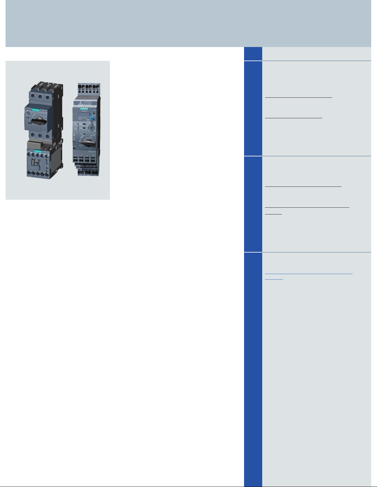
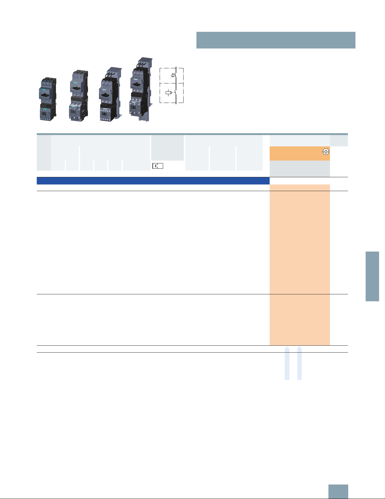
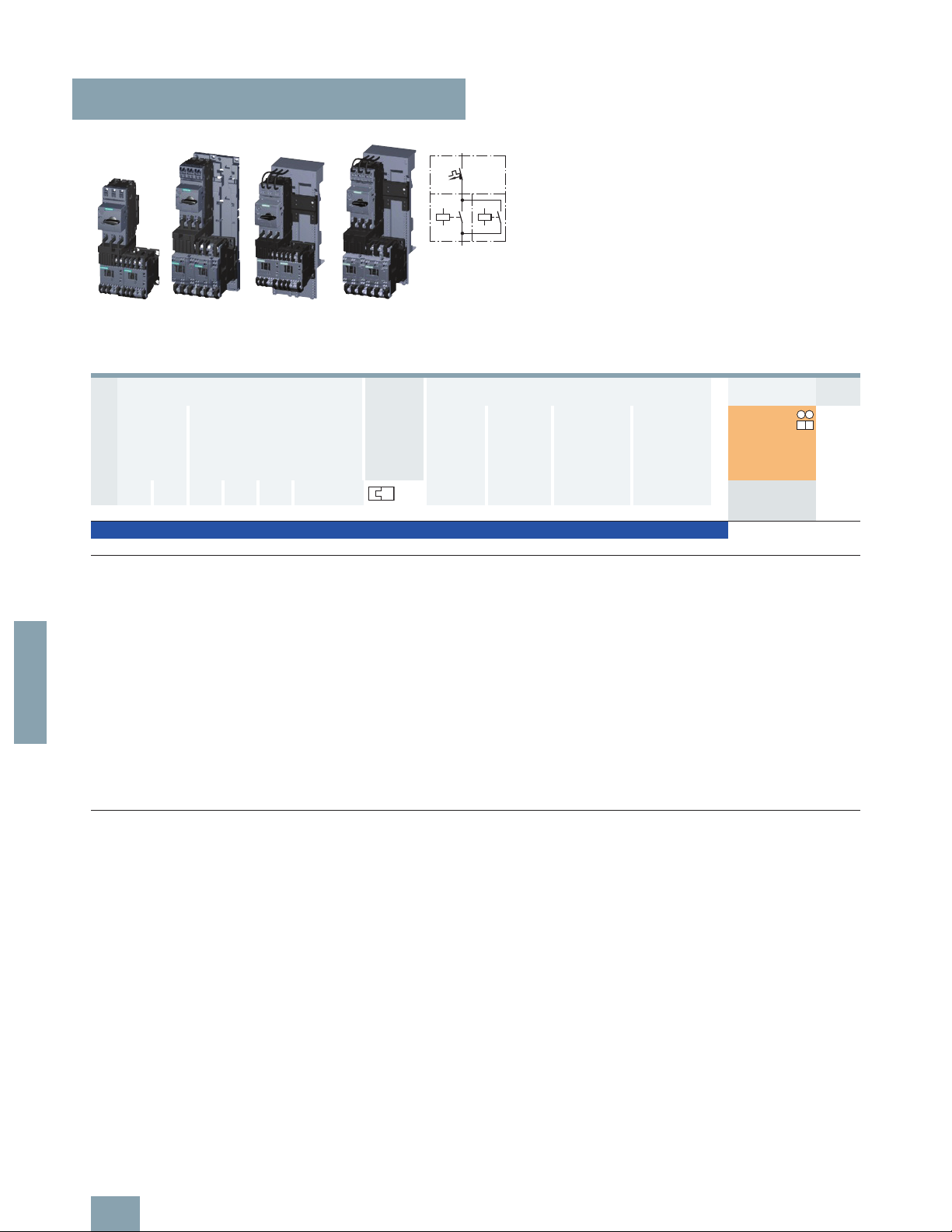
Direct-on-line starting • For standard rail mounting or screw fixing • Sizes S00 and S0
Left: 3RA21 motor starter with screw connection
Center: 3RA21 motor starter with spring-type connection
Right: Motor starter protector combination with screw connection, with contactor with spring-type connection
Left: Motor starter protector combination with solid-state switching device with screw connection
Right: Motor starter protector combination with soft starter with spring-type connection
NSB0_02089
2 push-in lugs
3RV29 28-0B
(only for screw
mounting)
2 push-in lugs
3RV29 28-0B
(only for screw
mounting)
Motor starter protector
Size S00/S0
Spring-type terminals
Contactor
Size S00/S0
Spring-type terminals
Link module
3RA29 11-2AA00 for S00
3RA29 21-2AA00 for S0
Motor starter protector
Size S00/S0
Screw terminals
Contactor
Size S00/S0
Spring-type terminals
Link module
3RA29 11-2FA00 for S00
3RA29 21-2FA00 for S0
2 push-in lugs
3RV29 28-0B
(only for screw
mounting)
Motor starter protector
Size S00/S0
Screw terminals
Contactor
Size S00/S0
Screw terminals
Link module
3RA19 21-1DA00
(for S00)
3RA29 21-1AA00
(for S0, AC contactor)
3RA29 21-1BA00
(for S0, DC contactor)
NSB0_02090
2 push-in lugs
3RV29 28-0B
(only for screw mounting)
Motor starter protector
Size S00/S0
Screw terminals
Solid-state
switching device
Link module
3RA29 21-1BA00
2 push-in lugs
3RV29 28-0B
(only for screw mounting)
Motor starter protector
Size S00/S0
Screw terminals/
spring-type terminals
Soft starter
Size S00/S0
Screw terminals/
spring-type terminals
Link module
3RA29 21-1BA00 for S00/S0 and screw terminals
3RA29 11-2GA00 for S00 and spring-type terminals
3RA29 21-2GA00 for S0 and spring-type terminals
© Siemens AG 2011
Page 6
Combination Starters & Starters for Group Installation
SIRIUS 3RA2 Motor Starters
General data
6/6
SIRIUS Innovations Supplement 2011
6
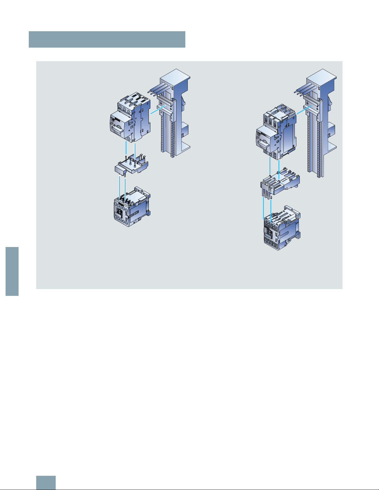
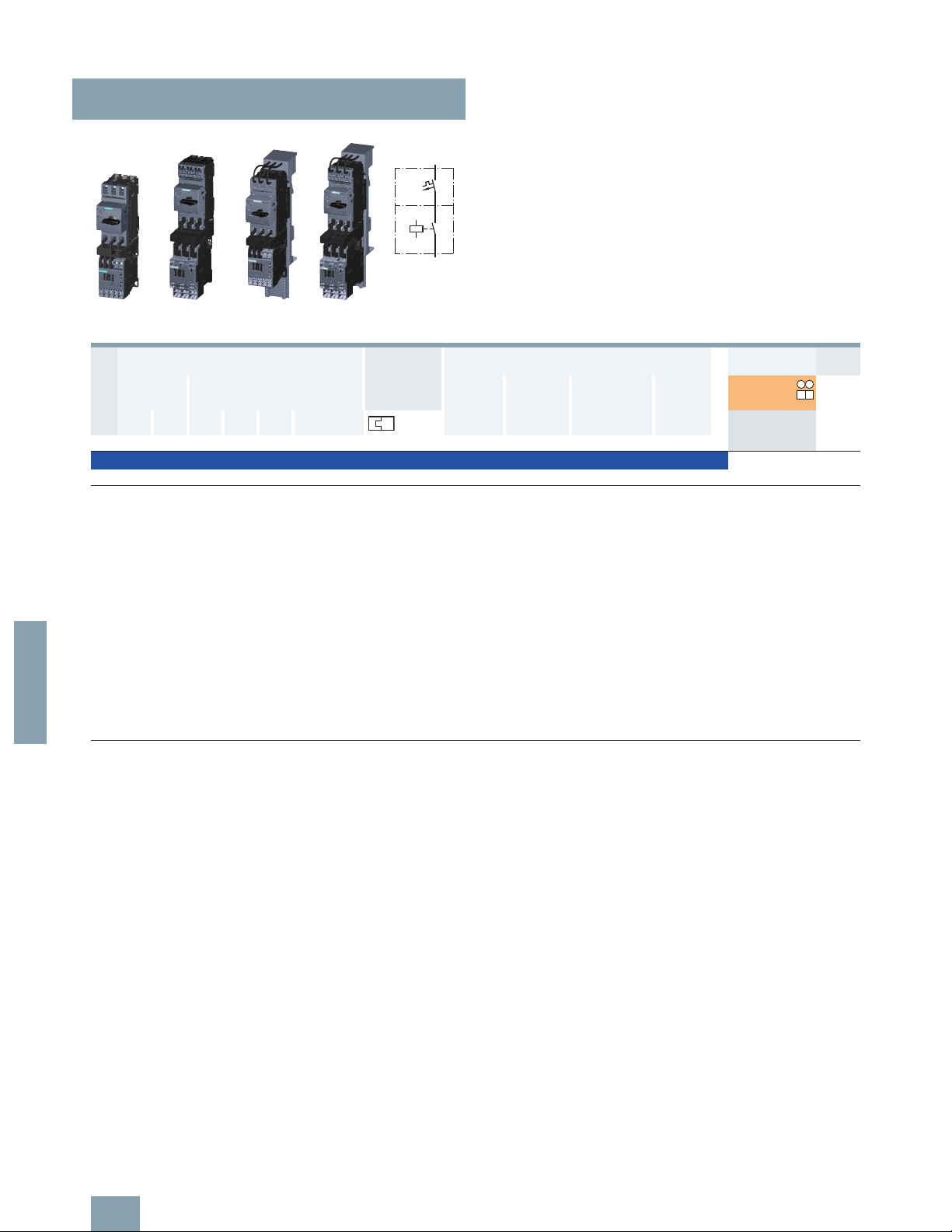
Direct-on-line starting • For 60 mm busbar systems • Sizes S00 and S0
Left: 3RA21 motor starter for direct-on-line starting with busbar adapters with screw connection
Right: 3RA21 motor starter for direct-on-line starting with busbar adapters with spring-type connection
NSB0_02091a
60 mm busbar adapter
for screw terminals
8US12 51-5DS10 for S00
8US12 51-5NT10 for S0
Motor starter protector
Size S00/S0
Screw terminals
Link module
3RA19 21-1DA00 for S00
3RA29 21-1AA00 for S0, AC contactor
3RA29 21-1BA00 for S0, DC contactor
Contactor
Size S00/S0
Screw terminals
60 mm busbar adapter
for spring-type terminals
8US12 51-5DT11 for S00
8US12 51-5NT11 for S0
Motor starter protector
Size S00/S0
Spring-type terminals
Link module
3RA29 11-2AA00 for S00
3RA29 21-2AA00 for S0
Contactor
Size S00/S0
Spring-type terminals
Additional 3RA29 11-1CA00 spacer
for height compensation on AC contactors
size S0 with spring-type terminals.
1)
1)
© Siemens AG 2011
Page 7

Combination Starters & Starters for Group Installation
SIRIUS 3RA2 Motor Starters
General data
6/7
SIRIUS Innovations Supplement 2011
6
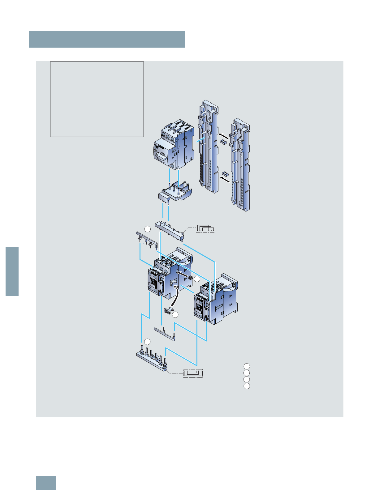
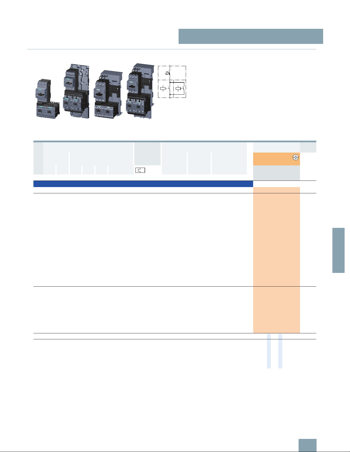
Reversing duty • For standard rail mounting or screw fixing • Size S00
Left: 3RA22 motor starter with screw connection, push-in lugs, 2 contactors for reversing duty and 3RA29 13-2AA1 wiring kit for connecting the
contactors (incl. mechanical interlocking and connecting clips)
Right: 3RA22 motor starter with spring-type connection, push-in lugs, 2 contactors for reversing duty and 3RA29 13-2AA2 wiring kit (incl. mechanical
interlocking and connecting clips)
NSB0_02092a
1
3
4
1
2
3
4
2
2 push-in lugs
3RV29 28-0B
(only for screw mounting)
Motor starter protector
Size S00
Screw terminals
Link module
3RA19 21-1DA00 for S00
2 contactors
Size S00
Screw terminals
2 push-in lugs
3RV29 28-0B
(only for screw mounting)
Motor starter protector
Size S00
Spring-type terminals
Link module
3RA29 11-2AA00 for S00
2 contactors
Size S00
Spring-type terminals
Wiring kit
3RA29 13-2AA1
Upper wiring module
Lower wiring module
2 connecting clips
Mechanical interlock
(can be removed if necessary)
Wiring kit
3RA29 13-2AA2
Upper wiring module
Lower wiring module
2 connecting clips
Mechanical interlock
(can be removed if necessary)
3
4
1
2
3
4
1
2
© Siemens AG 2011
Page 8
Combination Starters & Starters for Group Installation
SIRIUS 3RA2 Motor Starters
General data
6/8
SIRIUS Innovations Supplement 2011
6
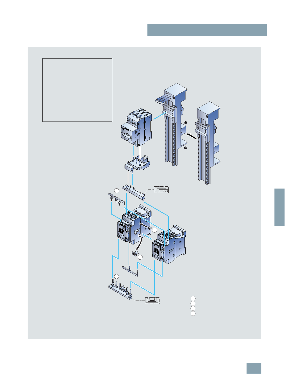
Reversing duty • For standard rail mounting • Size S0
3RA22 motor starter for reversing duty and standard rail mounting in size S0
(the version with screw connection is shown in the picture)
NSB0_02093b
3
4
1
2
Motor starter protector
Size S0
Screw terminals/
spring-type terminals
2 standard mounting
rail adapters
3RA29 22-1AA00
with 2 connecting wedges
8US19 98-1AA00
2 contactors
Size S0
Screw terminals/
spring-type terminals
Wiring kit
For screw terminals:
3RA29 23-2AA1
For spring-type terminals:
3RA29 23-2AA2
Upper wiring module
Lower wiring module
2 connecting clips
Mechanical interlock
(can be removed if necessary)
RH assembly kit for reversing duty and
standard rail mounting in size S0
For screw terminals:
3RA29 23-1BB1
For spring-type terminals:
3RA29 23-1BB2
1)
Comprising:
1 wiring kit
2 standard mounting rail adapters
2 connecting wedges
Link module
For screw terminals:
3RA29 21-1AA00 (AC)
3RA29 21-1BA00 (DC)
For spring-type terminals:
3RA29 21-2AA00
Additional 3RA29 11-1CA00 spacer
for height compensation on AC contactors
size S0 with spring-type terminals
3
4
1
2
1)
Also includes 3RA29 11-1CA00 spacer for
height compensation on AC contactors size S0
with spring-type terminals.
2)
2)
© Siemens AG 2011
Page 9
Combination Starters & Starters for Group Installation
SIRIUS 3RA2 Motor Starters
General data
6/9
SIRIUS Innovations Supplement 2011
6
Reversing duty • For 60 mm busbar systems • Sizes S00 and S0
3RA22 motor starter for reversing duty and 60 mm standard mounting rail in size S00/S0
(the version with screw connection is shown in the picture)
NSB0_02094b
3
4
1
2
Motor starter protector
Size S00/S0
Screw terminals/
spring-type terminals
2 contactors
Size S00/S0
Screw terminals/
spring-type terminals
Wiring kit
Screw connection:
3RA29 13-2AA1 for S00
3RA29 23-2AA1 for S0
Spring-type connection:
3RA29 13-2AA2 for S00
3RA29 23-2AA2 for S0
Upper wiring module
Lower wiring module
2 connecting clips
Mechanical interlock
(can be removed if necessary)
3
4
1
2
RS assembly kit for reversing duty and
busbar mounting
Screw connection:
3RA29 13-1DB1 for S00
3RA29 23-1DB1 for S0
For spring-type connection:
3RA29 13-1DB2 for S00
3RA29 23-1DB2 for S0
Comprising:
1 wiring kit
1 busbar adapter
1 device holder
2 connecting wedges
Link module
For screw terminals:
3RA19 21-1DA00 for S00
3RA29 21-1AA00 for S0, AC contactor
3RA29 21-1BA00 for S0, DC contactor
For spring-type terminals:
3RA29 11-2AA00 for S00
3RA29 21-2AA00 for S0
Additional 3RA29 11-1CA00 spacer
for height compensation on AC contactors
size S0 with spring-type terminals.
60 mm busbar adapter
For screw terminals:
8US12 51-5DS10 for S00
8US12 51-5NT10 for S0
For spring-type terminals:
8US12 51-5DT11 for S00
8US12 51-5NT11 for S0
2 connecting wedges
8US19 98-1AA00
60 mm device holder
8US12 51-5AS10
Also includes 3RA29 11-1CA00 spacer
for height compensation on AC contactors
size S0 with spring-type terminals.
1)
1)
2)
2)
© Siemens AG 2011
Page 10
Combination Starters & Starters for Group Installation
SIRIUS 3RA2 Motor Starters
General data
6/10
SIRIUS Innovations Supplement 2011
6
Order No. scheme
Note:
The Order No. scheme is presented here merely for information purposes and for better understanding of the logic behind the order
numbers.
For your orders, please use the order numbers quote in the catalog in the Selection and ordering data.
■
Technical specifications
Digit of the Order No. 1st -
3rd
4th 5th 6th 7th 8th 9th 10th 11th 12th 13th 14th 15th 16th
@@@ @ @ @ 0 – @ @ @ @ @ – @ @ @ @
SIRIUS starters 3 R A
SIRIUS 2nd generation 2
Type of starter (direct-on-line starter = 1,
reversing starter = 2)
@
Size (S00 = 1, S0 = 2) @
Setting range for overload release @ @
Design type and connection method @
Rated power at 460 V AC @ @
Integrated auxiliary switches of the contactor @
Operating range / solenoid coil circuit (contactor) @
Rated control supply voltage (contactor) @ @
Example
3 R A 2 1 1 0 – 0 B A 1 5 – 1 A K 6
Direct-on-line starters/
reversing starters
Size Connection methods Mounting Control voltage Width W Height H Depth D
mm mm mm
Mounting dimensions
Direct-on-line starters
3RA21.
S00
3RA21 1.
Screw terminals Standard mounting rails AC/DC 45 167 97
Busbar adapters AC/DC
45 200 155
Spring-type terminals Standard mounting rails AC/DC
45 198 97
Busbar adapters AC/DC
45 260 155
S0
3RA21 2.
Screw terminals Standard mounting rails AC
45 193 97
DC
45 193 107
Busbar adapters AC
45 260 155
DC
45 260 165
Spring-type terminals Standard mounting rails AC/DC
45 243 107
Busbar adapters AC/DC
45 260 165
Reversing starters
3RA22.
S00
3RA22 1.
Screw terminals Standard mounting rails AC/DC
90 170 97
Busbar adapters AC/DC
90 200 155
Spring-type terminals Standard mounting rails AC/DC
90 204 97
Busbar adapters AC/DC
90 260 155
S0
3RA22 2.
Screw terminals Standard mounting rail
adapters
AC
90 265 120.3
DC
90 265 130
Busbar adapters AC
90 260 155
DC
90 260 165
Spring-type terminals Standard mounting rail
adapters
AC/DC
90 270 131
Busbar adapters AC/DC
90 260 165
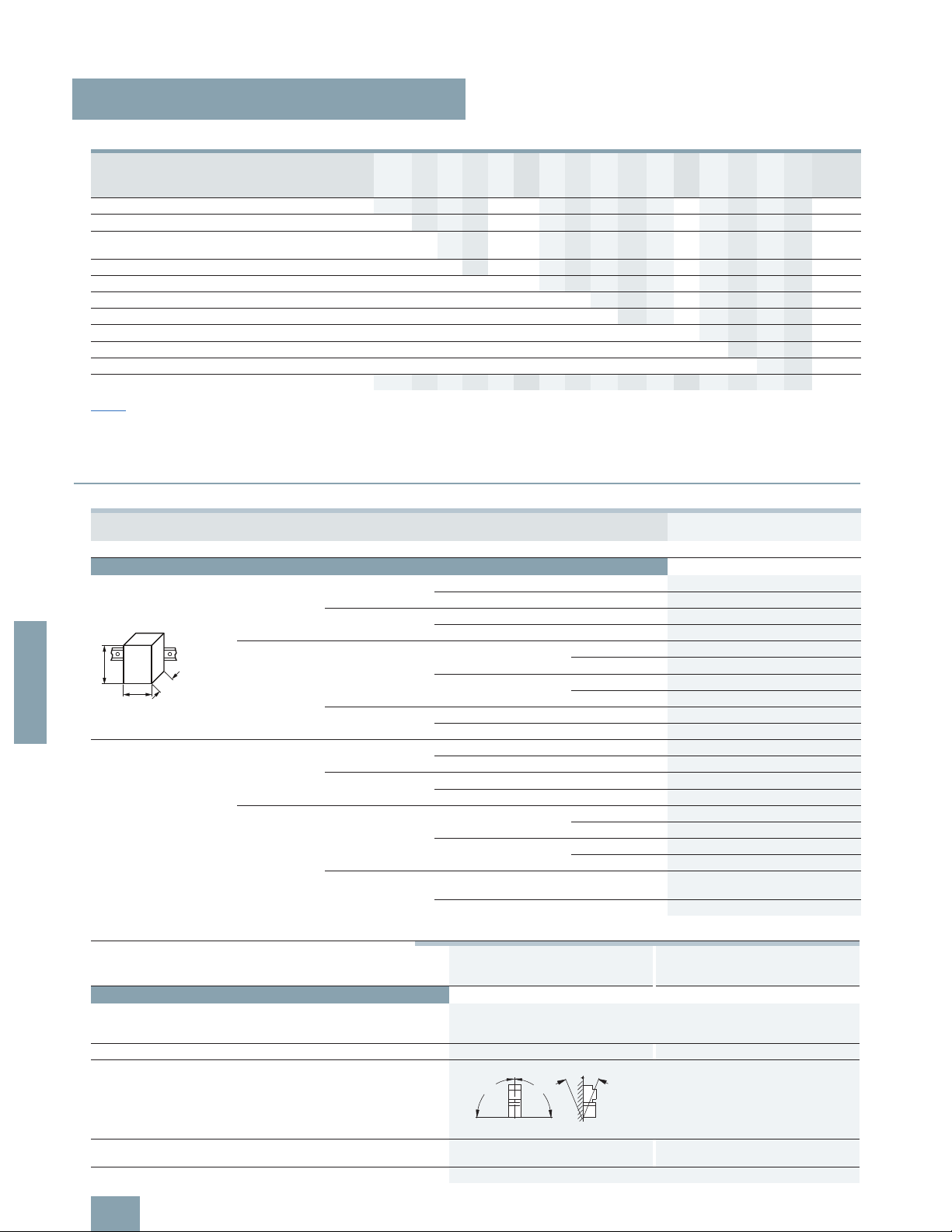
W
H
D
Type
3RA2. 1 3RA2. 2
Size
S00 S0
Number of poles
3 3
Mechanics and environment
Permissible ambient temperature
• During operation °C -20 ... +60
• Storage and transport °C
-55 ... +80
Weight kg 0.6 ... 1.5 0.8 ... 2.3
Permissible mounting
positions
Important: Acc. to DIN 43602 start command "I" at the right or top
Shock resistance
(sine-wave pulse)
Acc. to IEC 60086 Part 2-27
g
Up to 6 Up to 6
Degree of protection Acc. to IEC 60947-1
IP20
90°
90°
NSB00369
22,5°
22,5°
© Siemens AG 2011
Page 11

Combination Starters & Starters for Group Installation
SIRIUS 3RA2 Motor Starters
General data
6/11
SIRIUS Innovations Supplement 2011
6
■
More information
Type 3RA2. 1 3RA2. 2
Size S00 S0
Number of poles
3 3
General data
Standards IEC 60947-1, EN 60947-1
IEC 60947-2, EN 60947-2
IEC 60947-4-1, EN 60947-4-1
Max. rated current I
n max
(= max. rated operational current Ie) A 16 32
Permissible ambient temperature °C
-20 ... +60 for operation
°C
-55 ... +80 during storage/transport
Rated operational voltage U
e
V 690
Rated frequency Hz
50/60
Rated insulation voltage U
i
(pollution degree 3) V 690
Rated impulse withstand voltage U
imp
kV 6
Trip class (CLASS) Acc. to IEC 60947-4-1,
EN 60947-4-1
10
Rated short-circuit current I
q
at AC 50/60 Hz 400 V
acc. to IEC 60947-4-1, EN 60947-4-1
kA 153
Power loss P
v max
of all main
current paths
Dependent on the rated current
I
n
(upper setting range)
Up to 1.25 A W
2
--
1.6 ... 6.3 A W
2.3 --
8 ... 12 A W
3.5 --
16 A W
4.3 --
5 ... 6.3 A W
-- 2.3
8 ... 12 A W
-- 3.5
16 ... 32 A W
-- 4.3
Power consumption of the solenoid coils for contactors
as a function of the standard output
P of the motor
(when coil is cold and
U
s’
50 Hz)
• AC operation
- Closing Up to 4 kW VA 27 --
5.5 ... 7.5 kW VA
37 --
Up to 5.5 kW VA
-- 65
7.5 ... 15 kW VA
-- 77
P.f.
0.8 0.82
- Closed Up to 4 kW VA
4.2 --
5.5 ... 7.5 kW VA
5.7 --
Up to 5.5 kW VA
-- 8.5
7.5 ... 15 kW VA
-- 9.8
P.f.
0.25 0.25
• DC operation Closing =
Closed
W
4 5.9
Solenoid coil operating range for contactors
0.8 ... 1.1 x U
s
Lower limit at 55 °C 0.8 x U
s
--
At 60 °C
0.85 x U
s
--
Endurance of the motor starter protector
• Mechanical endurance Operating cycles 100 000
• Electrical endurance Operating cycles
100000
• Max. switching frequency per hour (motor starts) 1/h
15
Endurance of contactor
• Mechanical endurance Operating cycles 30 million 10 million
• Electrical endurance Operating cycles
See endurance characteristic curves of the contactors -->
Chapter 3 "Controls – Contactors and Contactor Assemblies"
Shock resistance (sine-wave
pulse)
Acc. to IEC 60086 Part 2-27 g
Up to 6 Up to 6
Degree of protection Acc. to IEC 60947-1
IP20
Touch protection Acc. to EN 50274
Finger-safe
Phase failure sensitivity
of the motor starter protector
Acc. to IEC 60947-1,
EN 60947-1
Yes
Isolating features
of the motor starter protector
Acc. to IEC 60947-2,
EN 60947-2
Yes
Main control and EMERGENCY-STOP switch characteristics of the motor starter
protector and accessories
Acc. to IEC 60204-1,
EN 60204-1
Yes
(with overvoltage releases of category "1" under conditions of proper use)
Protective separation between
main and auxiliary circuits
Acc. to EN 60947-1,
Appendix N
V
Up to 400
Mirror contacts for contactors
Yes Yes, from main contact to auxiliary
NC contact
© Siemens AG 2011
Page 12

Combination Starters & Starters for Group Installation
SIRIUS 3RA2 Motor Starters
General data
6/12
SIRIUS Innovations Supplement 2011
6
1)
If two different conductor cross-sections are connected to one clamping
point, both cross-sections must lie in the range specified. If identical crosssections are used, this restriction does not apply.
Type SIRIUS 3RA2 Motor Starters
Connection type
Screw terminals Spring-type terminals
Conductor cross-sections for main conductors
Size S00
Motor starter protectors, contactors Motor starter protectors, contactors
Terminal screw
M3, Pozidriv size 2 --
Operating devices mm
! 5 ... 6 3.0 x 0.5 and 3.5 x 0.5
Prescribed tightening torque Nm
0.8 ... 1.2 --
Conductor cross-sections (min./max.),
1 or 2 conductors can be connected
• Solid and stranded mm22 x (0.5 … 1.5)1) only for contactors,
mm22 x (0.75 ... 2.5)1), 2 x (0.5 ... 4)
mm
2
max. 2 x 4
• Finely stranded without end sleeve mm2-- 2 x (0.5 ... 2.5)
• Finely stranded with end sleeves (DIN 46 228 T1) mm22 x (0.5 ... 1.5)1). 2 x (0.5 ... 2.5)
mm
2
2 x (0.75 ... 2.5)1)
• AWG cables, solid or stranded AWG 2 x (20 … 16)1) only for contactors,
AWG 2 x (18 ... 14)1), 2 x (20 ... 12)
AWG
2 x 12
Max. external diameter of the conductor insulation mm -- 3.6
Conductor cross-sections for main conductors
Size S0
Motor starter protectors, contactors Motor starter protectors, contactors
Terminal screw
M4, Pozidriv size 2 --
Operating devices mm
! 5 ... 6 3.0 x 0.5 and 3.5 x 0.5
Prescribed tightening torque Nm
2.0 ... 2.5 --
Conductor cross-sections (min./max.),
1 or 2 conductors can be connected
• Solid and stranded mm22 x (1.0 ... 2.5)1), 2 x (1.0 ... 10)
mm
2
2 x (2.5 ... 10)1)
• Finely stranded without end sleeve mm2-- 2 x (1.0 ... 6.0)
• Finely stranded with end sleeves (DIN 46 228 T1) mm22 x (1.0 ... 2.5)1), 2 x (1.0 ... 6.0)
mm
2
2 x (2.5 ... 6)1)
mm2max. 1 x 10
• AWG cables, solid or stranded AWG 2 x (16 ... 12)1), 2 x (18 ... 8)
AWG
2 x (14 ... 8)1)
Max. external diameter of the conductor insulation mm -- 3.6
Conductor cross-sections for auxiliary
conductors, Size S00/S0
Contactors (basic unit),
motor starter protectors (accessories),
contactors (mountable accessories),
overload relays
Contactors S00 Contactors S0,
motor starter protectors (accessories),
contactors
(accessories),
overload relays
Terminal screw
M3, Pozidriv size 2 --
Operating devices mm
! 5 ... 6 3.0 x 0.5 and 3.5 x 0.5
Prescribed tightening torque Nm
0.8 ... 1.2 --
Conductor cross-sections (min./max.),
1 or 2 conductors can be connected
• Solid and stranded mm22 x (0.5 ... 1.5)1), 2 x (0.5 ... 4) 2 x (0.5 ... 2.5)
mm
2
2 x (0.75 ... 2.5)1),
mm2max. 2 x 4 only for contactors S00
• Finely stranded without end sleeve mm2-- 2 x (0.5 ... 2.5) 2 x (0.5 ... 1.5)
• Finely stranded with end sleeve mm22 x (0.5 ... 1.5)1), 2 x (0.5 ... 2.5) 2 x (0.5 ... 1.5)
mm
2
2 x (0.75 ... 2.5)1)
• AWG cables, solid or stranded AWG 2 x (20 ... 16)1), 2 x (20 ... 12) 2 x (20 ... 14)
AWG
2 x (18 ... 14)1),
AWG 2 x 12 only for contactors S00
Max. external diameter of the conductor insulation mm -- 3.6 3.6
© Siemens AG 2011
Page 13

Combination Starters & Starters for Group Installation
SIRIUS 3RA2 Motor Starters
3RA21 direct-on-line starters
50/60 Hz 110/120 V AC
6/13
SIRIUS Innovations Supplement 2011
Illustrations are approximate
6
■
Selection and ordering data
Rated control supply voltage 50/60 Hz 110/120 V AC
With screw connections
• The motor starter protector and contactor are mechanically
and electrically connected by means of the link module.
• Auxiliary switches
1)
on the motor starter protector and the con-
tactor can be easily fitted due to the modular system.
• Integrated auxiliary switches:
- Contactor size S00: 1 NO;
- Contactor size S0: 1 NO + 1 NC
Combination Starter, UL508 Type F
All size S00 and S0 devices can be applied as Combination
Starters with the addition of either of these line side connectors:
3RV29 28-1H, 3RV29 25-5EB or 3RV29 28-1K.
1)
For auxiliary switches see Accessories page 6/21.
2)
Selection depends on the motor full load amps. HP ratings for reference
only.
3)
Used only for mounting starter on 8US Fast Bus busbar systems.
3RA21 10
3RA21 20 3RA21 10 3RA21 20
Direct-on-line
starting
Size UL Data FLA setting
range inversetime delayed
overload
release
Consisting of the following single
devices
Assembled starter Weight
approx.
Single-phase
HP ratings
Three-phase2)
HP ratings
SCCR
at
480 V
Motor
starter
protector
+ Contactor + Link
module
+ Busbar
adapter
3)
Screw terminals
115 V 230 V 200 V 230 V 460 V 575 V Order No.
kA A kg
Selection depends on motor full load amps
3RV20 3RT20 3RA
S00 -- -- -- -- -- -- 65 0.14…0.2 11-0BA10 15-1AK61 1921-1DA00
+ 8US12515DS10
3RA21 10-0B@15-1AK6 0.575
-- -- -- -- -- -- 65 0.18…0.25 11-0CA10
3RA21 10-0C@15-1AK6 0.575
-- -- -- -- -- -- 65 0.22…0.32 11-0DA10
3RA21 10-0D@15-1AK6 0.575
-- -- -- -- -- -- 65 0.28…0.4 11-0EA10
3RA21 10-0E@15-1AK6 0.575
-- -- -- -- -- -- 65 0.35…0.5 11-0FA10
3RA21 10-0F@15-1AK6 0.575
-- -- -- -- -- -- 65 0.45…0.63 11-0GA10
3RA21 10-0G@15-1AK6 0.575
-- -- -- -- -- -- 65 0.55…0.8 11-0HA10
3RA21 10-0H@15-1AK6 0.575
-- -- -- -- -- 1/2 65 0.7… 1 11-0JA10
3RA21 10-0J@15-1AK6 0.575
-- -- -- -- 1/2 1/2 65 0.9… 1.25 11-0KA10
3RA21 10-0K@15-1AK6 0.575
-- 1/10 -- -- 3/4 3/4 65 1.1… 1.6 11-1AA10
3RA21 10-1A@15-1AK6 0.575
-- 1/8 -- -- 3/4 1 65 1.4… 2 11-1BA10
3RA21 10-1B@15-1AK6 0.575
-- 1/6 1/2 1/2 1 1 1/2 65 1.8… 2.5 11-1CA10
3RA21 10-1C@15-1AK6 0.575
1/10 1/4 1/2 3/4 1 1/2 2 65 2.2… 3.2 11-1DA10
3RA21 10-1D@15-1AK6 0.575
1/8 1/3 3/4 3/4 2 3 65 2.8… 4 11-1EA10
3RA21 10-1E@15-1AK6 0.575
1/6 1/2 1 1 3 3 65 3.5… 5 11-1FA10
3RA21 10-1F@15-1AK6 0.575
1/4 1/2 1 1 1/2 3 5 65 4.5… 6.3 11-1GA10
3RA21 10-1G@15-1AK6 0.575
1/3 1 2 2 5 5 65 5.5… 8 11-1HA10 16-1AK61
3RA21 10-1H@16-1AK6 0.575
1/2 1 1/2 2 3 5 7 1/2 65 7… 10 11-1JA10
3RA21 10-1J@16-1AK6 0.575
1/2 2 3 3 7 1/2 10 65 9… 12 11-1KA10 17-1AK61
3RA21 10-1K@17-1AK6 0.575
1 2 3 5 10 -- 65 11… 16 11-4AA10 18-1AK61
3RA21 10-4A@18-1AK6 0.575
S0 1/6 1/2 1 1 3 3 65 3.5… 5 11-1FA10 24-1AK60 2921-1AA00
+ 8US12515NT10
3RA21 20-1F@24-0AK6 0.761
1/4 1/2 1 1 1/2 3 5 65 4.5… 6.3 11-1GA10
3RA21 20-1G@24-0AK6 0.761
1/3 1 2 2 5 5 65 5.5… 8 11-1HA10
3RA21 20-1H@24-0AK6 0.761
1/2 1 1/2 2 3 5 7 1/2 65 7… 10 11-1JA10
3RA21 20-1J@24-0AK6 0.761
1/2 2 3 3 7 1/2 10 65 9… 12.5 11-1KA10
3RA21 20-1K@24-0AK6 0.761
1 2 3 5 10 -- 65 11… 16 21-4AA10 26-1AK60
3RA21 20-4A@26-0AK6 0.761
1 1/2 3 5 5 10 -- 65 14… 20 21-4BA10
3RA21 20-4B@26-0AK6 0.761
1 1/2 3 5 7 1/2 15 -- 50 17… 22 21-4CA10 27-1AK60
3RA21 20-4C@27-0AK6 0.761
2 3 5 7 1/2 15 -- 50 20… 25 21-4DA10
3RA21 20-4D@27-0AK6 0.761
2 5 7 1/2 10 20 -- 50 27… 32 21-4EA10
3RA21 20-4E@27-0AK6 0.761
Add. weight
Order No. supplement for mounting onto standard mounting rail or screw fixing A
Screw fixing with 1 push-in lug each per motor starter is possible
(see "Accessories for Direct-On-Line and Reversing Starters").
Order No. supplement for mounting onto 60 mm busbar for size S00 1 D 0.263
With busbar adapter for size S0 2 D 0.295
© Siemens AG 2011
Page 14

Combination Starters & Starters for Group Installation
SIRIUS 3RA2 Motor Starters
3RA21 direct-on-line starters
50/60 Hz 110/120 V AC
6/14
SIRIUS Innovations Supplement 2011
Illustrations are approximate
6
Rated control supply voltage 50/60 Hz 110/120 V AC
With spring-type connection
• These starters can be assembled in the field without tools by
simply snapping the components together. Follow the simple
component selection system to form a starter.
• Auxiliary switches
1)
on the motor starter protector and the con-
tactor can be easily fitted due to the modular system.
• Integrated auxiliary switches:
- Contactor size S00: 1 NO;
- Contactor size S0: 1 NO + 1 NC
Combination Starter, UL508 Type F
All size S00 and S0 devices can be applied as Combination
Starters with the addition of either of these line side connectors:
3RV29 28-1H, 3RV29 25-5EB or 3RV29 28-1K.
1)
For auxiliary switches see Accessories page 6/21.
2)
Selection depends on motor full load amps. HP ratings for reference only.
3)
Use only for mounting starter on 8US Fast Bus busbar systems.
4)
Mounting on standard mounting rails with adapter (3RA29 22-1AA00) is
possible for feeder-orientated assembly, in which case the contactor must
be screwed onto the adapter.
5)
For the AC version size S0 with spring loaded terminals, a 3RA29 111CA00 spacer is required for height compensation of the contactor.
3RA21 10
3RA21 20 3RA21 10 3RA21 20
Direct-on-line
starting
Size UL Data FLA setting
range inversetime delayed
overload
release
Consisting of the following single devices Not available
pre-assembled
Weight
approx.
Single-phase
HP ratings
Three-phase2)
HP ratings
SCCR
at
480 V
Motor
starter
protector
+ Contactor + Link module + Busbar
adapter
3)
Spring-type
terminals
115 V 230 V 200 V 230 V 460 V 575 V Order No.
kA A kg
Selection depends on motor full load amps
3RV20 3RT20 3RA 8US12
S00 -- -- -- -- -- -- 65 0.14…0.2 11-0BA20 15-2AK61 2911-2AA00 51-5DT11 0.641
-- -- -- -- -- -- 65 0.18…0.25 11-0CA20 0.641
-- -- -- -- -- -- 65 0.22…0.32 11-0DA20 0.641
-- -- -- -- -- -- 65 0.28…0.4 11-0EA20 0.641
-- -- -- -- -- -- 65 0.35…0.5 11-0FA20 0.641
-- -- -- -- -- -- 65 0.45…0.63 11-0GA20 0.641
-- -- -- -- -- -- 65 0.55…0.8 11-0HA20 0.641
-- -- -- -- -- 1/2 65 0.7… 1 11-0JA20 0.641
-- -- -- -- 1/2 1/2 65 0.9… 1.25 11-0KA20 0.641
-- 1/10 -- -- 3/4 3/4 65 1.1… 1.6 11-1AA20 0.641
-- 1/8 -- -- 3/4 1 65 1.4… 2 11-1BA20 0.641
-- 1/6 1/2 1/2 1 1 1/2 65 1.8… 2.5 11-1CA20 0.641
1/10 1/4 1/2 3/4 1 1/2 2 65 2.2… 3.2 11-1DA20 0.641
1/8 1/3 3/4 3/4 2 3 65 2.8… 4 11-1EA20 0.641
1/6 1/2 1 1 3 3 65 3.5… 5 11-1FA20 0.641
1/4 1/2 1 1 1/2 3 5 65 4.5… 6.3 11-1GA20 0.641
1/3 1 2 2 5 5 65 5.5… 8 11-1HA20 16-2AK61 0.641
1/2 1 1/2 2 3 5 7 1/2 65 7… 10 11-1JA20 0.641
1/2 2 3 3 7 1/2 10 65 9… 12 11-1KA20 17-1AK61 0.641
1 2 3 5 10 -- 65 11… 16 11-4AA20 18-2AK61 0.641
S0 1/6 1/2 1 1 3 3 65 3.5… 5 11-1FA20 24-2AK60 2921-2AA00
4)
+2911-1CA00
5)
51-5NT11 0.925
1/4 1/2 1 1 1/2 3 5 65 4.5… 6.3 11-1GA20 0.925
1/3 1 2 2 5 5 65 5.5… 8 11-1HA20 0.925
1/2 1 1/2 2 3 5 7 1/2 65 7… 10 11-1JA20 0.925
1/2 2 3 3 7 1/2 10 65 9… 12.5 11-1KA20 0.925
1 2 3 5 10 -- 65 11… 16 21-4AA20 26-2AK60 0.925
1 1/2 3 5 5 10 -- 65 14… 20 21-4BA20 0.925
1 1/2 3 5 7 1/2 15 -- 50 17… 22 21-4CA20 27-2AK60 0.925
2 3 5 7 1/2 15 -- 50 20… 25 21-4DA20 0.925
2 5 7 1/2 10 20 -- 50 27… 32 21-4EA20 0.925
Screw fixing with 1 push-in lug each per motor starter is possible
(see "Accessories for Direct-On-Line and Reversing Starters").
© Siemens AG 2011
Page 15
Combination Starters & Starters for Group Installation
SIRIUS 3RA2 Motor Starters
3RA21 direct-on-line starters
24 V DC
6/15
SIRIUS Innovations Supplement 2011
Illustrations are approximate
6
Rated control supply voltage 24 V DC
With screw connections
• The motor starter protector and contactor are mechanically
and electrically connected by means of the link module.
• Auxiliary switches
1)
on the motor starter protector and the con-
tactor can be easily fitted due to the modular system.
• Integrated auxiliary switches:
- Contactor size S00: 1 NO;
- Contactor size S0: 1 NO + 1 NC
Combination Starter, UL508 Type F
All size S00 and S0 devices can be applied as Combination
Starters with the addition of either of these line side connectors:
3RV29 28-1H, 3RV29 25-5EB or 3RV29 28-1K.
1)
For auxiliary switches see Accessories page 6/21.
2)
Selection depends on the concrete motor full load amps. HP ratings for
reference only.
3)
Use only for mounting starter on 8US Fast Bus busbar systems.
3RA21 10
3RA21 20 3RA21 10 3RA21 20
Direct-on-line
starting
Size UL Data FLA setting
range inversetime delayed
overload
release
Consisting of the following
single devices
Assembled starter Weight
approx.
Single-phase
HP ratings
Three-phase2)
HP ratings
SCCR
at
480 V
Motor
starter
protector
+ Contactor + Link
module
+ Busbar
adapter
3)
Screw terminals
115 V 230 V 200 V 230 V 460 V 575 V Order No.
kA A kg
Selection depends on motor full load amps
3RV20 3RT20 3RA
S00 -- -- -- -- -- -- 65 0.14…0.2 11-0BA10 15-1BB41 1921-1DA00
+ 8US12515DS10
3RA21 10-0B@15-1BB4 0.630
-- -- -- -- -- -- 65 0.18…0.25 11-0CA10
3RA21 10-0C@15-1BB4 0.630
-- -- -- -- -- -- 65 0.22…0.32 11-0DA10
3RA21 10-0D@15-1BB4 0.630
-- -- -- -- -- -- 65 0.28…0.4 11-0EA10
3RA21 10-0E@15-1BB4 0.630
-- -- -- -- -- -- 65 0.35…0.5 11-0FA10
3RA21 10-0F@15-1BB4 0.630
-- -- -- -- -- -- 65 0.45…0.63 11-0GA10
3RA21 10-0G@15-1BB4 0.630
-- -- -- -- -- -- 65 0.55…0.8 11-0HA10
3RA21 10-0H@15-1BB4 0.630
-- -- -- -- -- 1/2 65 0.7… 1 11-0JA10
3RA21 10-0J@15-1BB4 0.630
-- -- -- -- 1/2 1/2 65 0.9… 1.25 11-0KA10
3RA21 10-0K@15-1BB4 0.630
-- 1/10 -- -- 3/4 3/4 65 1.1… 1.6 11-1AA10
3RA21 10-1A@15-1BB4 0.630
-- 1/8 -- -- 3/4 1 65
1.4… 2
11-1BA10
3RA21 10-1B@15-1BB4 0.630
-- 1/6 1/2 1/2 1 1 1/2 65 1.8… 2.5 11-1CA10
3RA21 10-1C@15-1BB4 0.630
1/10 1/4 1/2 3/4 1 1/2 2 65 2.2… 3.2 11-1DA10
3RA21 10-1D@15-1BB4 0.630
1/8 1/3 3/4 3/4 2 3 65 2.8… 4 11-1EA10
3RA21 10-1E@15-1BB4 0.630
1/6 1/2 1 1 3 3 65 3.5… 5 11-1FA10
3RA21 10-1F@15-1BB4 0.630
1/4 1/2 1 1 1/2 3 5 65 4.5… 6.3 11-1GA10
3RA21 10-1G@15-1BB4 0.630
1/3 1 2 2 5 5 65 5.5… 8 11-1HA10 16-1BB41 3RA21 10-1H@16-1BB4 0.630
1/2 1 1/2 2 3 5 7 1/2 65 7… 10 11-1JA10
3RA21 10-1J@16-1BB4 0.630
1/2 2 3 3 7 1/2 10 65 9… 12 11-1KA10 17-1BB41
3RA21 10-1K@17-1BB4 0.630
1 2 3 5 10 -- 65 11… 16 11-4AA10 18-1BB41
3RA21 10-4A@18-1BB4 0.630
S0 1/6 1/2 1 1 3 3 65 3.5… 5 11-1FA10 24-1BB40 2921-1BA00
+ 8US12515NT10
3RA21 20-1F@24-0BB4 0.948
1/4 1/2 1 1 1/2 3 5 65 4.5… 6.3 11-1GA10
3RA21 20-1G@24-0BB4 0.948
1/3 1 2 2 5 5 65 5.5… 8 11-1HA10
3RA21 20-1H@24-0BB4 0.948
1/2 1 1/2 2 3 5 7 1/2 65 7… 10 11-1JA10
3RA21 20-1J@24-0BB4 0.948
1/2 2 3 3 7 1/2 10 65 9… 12.5 11-1KA10
3RA21 20-1K@24-0BB4 0.948
1 2 3 5 10 -- 65 11… 16 21-4AA10 26-1BB40
3RA21 20-4A@26-0BB4 0.948
1 1/2 3 5 5 10 -- 65 14… 20 21-4BA10
3RA21 20-4B@26-0BB4 0.948
1 1/2 3 5 7 1/2 15 -- 50 17… 22 21-4CA10 27-1BB40
3RA21 20-4C@27-0BB4 0.948
2 3 5 7 1/2 15 -- 50 20… 25 21-4DA10
3RA21 20-4D@27-0BB4 0.948
2 5 7 1/2 10 20 -- 50 27… 32 21-4EA10
3RA21 20-4E@27-0BB4 0.948
Add. weight
Order No. supplement for mounting onto standard mounting rail or screw fixing A
Screw fixing with 1 push-in lug each per motor starter is possible
(see "Accessories for Direct-On-Line and Reversing Starters").
Order No. supplement for mounting onto 60 mm busbar for size S00 1 D 0.263
With busbar adapter for size S0 2 D 0.301
© Siemens AG 2011
Page 16
Combination Starters & Starters for Group Installation
SIRIUS 3RA2 Motor Starters
3RA21 direct-on-line starters
24 V DC
6/16
SIRIUS Innovations Supplement 2011
Illustrations are approximate
6
Rated control supply voltage 24 V DC
With spring-type connection
• These starters can be assembled in the field without tools by
simply snapping the components together. Follow the simple
component selection system to form a starter.
• Auxiliary switches
1)
on the motor starter protector and the con-
tactor can be easily fitted due to the modular system.
• Integrated auxiliary switches:
- Contactor size S00: 1 NO;
- Contactor size S0: 1 NO + 1 NC
Combination Starter, UL508 Type F
All size S00 and S0 devices can be applied as Combination
Starters with the addition of either of these line side connectors:
3RV29 28-1H, 3RV29 25-5EB or 3RV29 28-1K.
1)
For auxiliary switches see Accessories page 6/21.
2)
Selection depends on the motor full load amps. HP ratings for reference
only.
3)
Used only for mounting starter on 8US Fast Bus busbar systems.
4)
Mounting on standard mounting rails or with screws (3RA29 22-1AA00) is
possible for feeder-orientated assembly, in which case the contactor must
be screwed onto the adapter.
3RA21 10
3RA21 20 3RA21 10 3RA21 20
Direct-on-line
starting
Size UL Data FLA setting
range inversetime delayed
overload
release
Consisting of the following single devices Not available
pre-assembled
Weight
approx.
Single-phase
HP ratings
Three-phase2)
HP ratings
SCCR
at
480 V
Motor
starter
protector
+ Contactor + Link module + Busbar
adapter
3)
Spring-type
terminals
115 V 230 V 200 V 230 V 460 V 575 V Order No.
kA A kg
Selection depends on motor full load amps
3RV20 3RT20 3RA 8US12
S00 -- -- -- -- -- -- 65 0.14…0.2 11-0BA20 15-2BB41 2911-2AA00 51-5DT11 0.641
-- -- -- -- -- -- 65 0.18…0.25 11-0CA20 0.641
-- -- -- -- -- -- 65 0.22…0.32 11-0DA20 0.641
-- -- -- -- -- -- 65 0.28…0.4 11-0EA20 0.641
-- -- -- -- -- -- 65 0.35…0.5 11-0FA20 0.641
-- -- -- -- -- -- 65 0.45…0.63 11-0GA20 0.641
-- -- -- -- -- -- 65 0.55…0.8 11-0HA20 0.641
-- -- -- -- -- 1/2 65 0.7… 1 11-0JA20 0.641
-- -- -- -- 1/2 1/2 65 0.9… 1.25 11-0KA20 0.641
-- 1/10 -- -- 3/4 3/4 65 1.1… 1.6 11-1AA20 0.641
-- 1/8 -- -- 3/4 1 65 1.4… 2 11-1BA20 0.641
-- 1/6 1/2 1/2 1 1 1/2 65 1.8… 2.5 11-1CA20 0.641
1/10 1/4 1/2 3/4 1 1/2 2 65 2.2… 3.2 11-1DA20 0.641
1/8 1/3 3/4 3/4 2 3 65 2.8… 4 11-1EA20 0.641
1/6 1/2 1 1 3 3 65 3.5… 5 11-1FA20 0.641
1/4 1/2 1 1 1/2 3 5 65 4.5… 6.3 11-1GA20 0.641
1/3 1 2 2 5 5 65 5.5… 8 11-1HA20 16-2BB41 0.641
1/2 1 1/2 2 3 5 7 1/2 65 7… 10 11-1JA20 0.641
1/2 2 3 3 7 1/2 10 65 9… 12 11-1KA20 17-2BB41 0.641
1 2 3 5 10 -- 65 11… 16 11-4AA20 18-2BB41 0.641
S0 1/6 1/2 1 1 3 3 65 3.5… 5 11-1FA20 24-2BB40 2921-2AA00 51-5NT11 0.925
1/4 1/2 1 1 1/2 3 5 65 4.5… 6.3 11-1GA20 0.925
1/3 1 2 2 5 5 65 5.5… 8 11-1HA20 0.925
1/2 1 1/2 2 3 5 7 1/2 65 7… 10 11-1JA20 0.925
1/2 2 3 3 7 1/2 10 65 9… 12.5 11-1KA20 0.925
1 2 3 5 10 -- 65 11… 16 21-4AA20 26-2BB40 0.925
1 1/2 3 5 5 10 -- 65 14… 20 21-4BA20 0.925
1 1/2 3 5 7 1/2 15 -- 50 17… 22 21-4CA20 27-2BB40 0.925
2 3 5 7 1/2 15 -- 50 20… 25 21-4DA20 0.925
2 5 7 1/2 10 20 -- 50 27… 32 21-4EA20 0.925
Screw fixing with 1 push-in lug each per motor starter is possible.
© Siemens AG 2011
Page 17
Combination Starters & Starters for Group Installation
SIRIUS 3RA2 Motor Starters
3RA22 reversing starters
50/60 Hz 110/120 V AC
6/17
SIRIUS Innovations Supplement 2011
Illustrations are approximate
6
■
Selection and ordering data
1)
For push-in lugs and auxiliary switches see Accessories.
2)
Selection depends on the motor full load amps. HP ratings for reference
only.
3)
According to ordering option:
RH = assembly kit for reversing duty with standard rail mounting adapter in
size S0.
RS = assembly kit for reversing duty with 8US Fast Bus busbar mounting.
4)
With standard rail mounting or screw fixing, the 3RA29 13-2AA1 wiring kit
is required for size S00.
3RA22 10 3RA22 20 3RA22 10 3RA22 20
Reversing duty
Rated control supply voltage 50/60 Hz 110/120 V AC
With screw connections
• The motor starter protector and contactor are mechanically and electrically connected by means of the link
module.
• Auxiliary switches
1)
on the motor starter protector and
the contactor can be easily fitted due to the modular
system.
• With the contactor S0, an integrated NO contact is
available for free use.
Combination Starter, UL508 Type F
All size S00 and S0 devices can be applied as Combination Starters with the addition of either of these line side
connectors: 3RV29 28-1H, 3RV29 25-5EB or
3RV29 28-1K.
Size UL Data FLA setting
range inversetime delayed
overload
release
Consisting of the following single devices Assembled starter Weight
approx.
Single-phase
HP ratings
Three-phase2)
HP ratings
SCCR
at
480 V
Motor starter
protector
+ 2 contactors
+ Link module
+ Assembly kit
RH/RS
3)
Screw terminals
115 V 230 V 200 V 230 V 460 V 575 V Order No.
kA A kg
Selection depends on motor full load amps
3RV20 3RT20 3RA
S00 -- -- -- -- -- -- 65 0.14…0.2 11-0BA10 15-1AK62 1921-1DA00
+ 2913-2AA1
4)
+ 2913-1DB1 (RS)
3RA22 10-0B@15-2AK6 0.824
-- -- -- -- -- -- 65 0.18…0.25 11-0CA10
3RA22 10-0C@15-2AK6 0.824
-- -- -- -- -- -- 65 0.22…0.32 11-0DA10
3RA22 10-0D@15-2AK6 0.824
-- -- -- -- -- -- 65 0.28…0.4 11-0EA10
3RA22 10-0E@15-2AK6 0.824
-- -- -- -- -- -- 65 0.35…0.5 11-0FA10
3RA22 10-0F@15-2AK6 0.824
-- -- -- -- -- -- 65 0.45…0.63 11-0GA10
3RA22 10-0G@15-2AK6 0.824
-- -- -- -- -- -- 65 0.55…0.8 11-0HA10
3RA22 10-0H@15-2AK6 0.824
-- -- -- -- -- 1/2 65 0.7… 1 11-0JA10
3RA22 10-0J@15-2AK6 0.824
-- -- -- -- 1/2 1/2 65 0.9… 1.25 11-0KA10
3RA22 10-0K@15-2AK6 0.824
-- 1/10 -- -- 3/4 3/4 65 1.1… 1.6 11-1AA10
3RA22 10-1A@15-2AK6 0.824
-- 1/8 -- -- 3/4 1 65 1.4… 2 11-1BA10
3RA22 10-1B@15-2AK6 0.824
-- 1/6 1/2 1/2 1 1 1/2 65 1.8… 2.5 11-1CA10
3RA22 10-1C@15-2AK6 0.824
1/10 1/4 1/2 3/4 1 1/2 2 65 2.2… 3.2 11-1DA10
3RA22 10-1D@15-2AK6 0.824
1/8 1/3 3/4 3/4 2 3 65 2.8… 4 11-1EA10
3RA22 10-1E@15-2AK6 0.824
1/6 1/2 1 1 3 3 65 3.5… 5 11-1FA10
3RA22 10-1F@15-2AK6 0.824
1/4 1/2 1 1 1/2 3 5 65 4.5… 6.3 11-1GA10
3RA22 10-1G@15-2AK6 0.824
1/3 1 2 2 5 5 65 5.5… 8 11-1HA10 16-1AK62 3RA22 10-1H@16-2AK6 0.824
1/2 1 1/2 2 3 5 7 1/2 65 7… 10 11-1JA10
3RA22 10-1J@16-2AK6 0.824
1/2 2 3 3 7 1/2 10 65 9… 12 11-1KA10 17-1AK62
3RA22 10-1K@17-2AK6 0.824
1 2 3 5 10 -- 65 11… 16 11-4AA10 18-1AK62
3RA22 10-4A@18-2AK6 0.824
S0 1/6 1/2 1 1 3 3 65 3.5… 5 11-1FA10 24-1AK60 2921-1AA00
+ 2923-1BB1 (RH)
+ 2923-1DB1 (RS)
3RA22 20-1F@24-0AK6 1.434
1/4 1/2 1 1 1/2 3 5 65 4.5… 6.3 11-1GA10
3RA22 20-1G@24-0AK6 1.434
1/3 1 2 2 5 5 65 5.5… 8 11-1HA10
3RA22 20-1H@24-0AK6 1.434
1/2 1 1/2 2 3 5 7 1/2 65 7… 10 11-1JA10
3RA22 20-1J@24-0AK6 1.434
1/2 2 3 3 7 1/2 10 65 9… 12.5 11-1KA10
3RA22 20-1K@24-0AK6 1.434
1 2 3 5 10 -- 65 11… 16 21-4AA10 26-1AK60
3RA22 20-4A@26-0AK6 1.434
1 1/2 3 5 5 10 -- 65 14… 20 21-4BA10
3RA22 20-4B@26-0AK6 1.434
1 1/2 3 5 7 1/2 15 -- 50 17… 22 21-4CA10 27-1AK60
3RA22 20-4C@27-0AK6 1.434
2 3 5 7 1/2 15 -- 50 20… 25 21-4DA10
3RA22 20-4D@27-0AK6 1.434
2 5 7 1/2 10 20 -- 50 27… 32 21-4EA10 3RA22 20-4E@27-0AK6 1.434
Add. weight
Order No. supplement for mounting onto standard mounting rail or screw fixing
• Without standard mounting rail adapter for size S00
4)
1 A
• With 2 standard mounting rail adapters for size S0 2 B
Screw fixing with 2 push-in lugs each per motor starter is possible
Order No. supplement for mounting onto 60 mm busbar for size S00 1 D 0.486
With 8US Fast Bus busbar adapter for size S0 2 D 0.293
© Siemens AG 2011
Page 18
Combination Starters & Starters for Group Installation
SIRIUS 3RA2 Motor Starters
3RA22 reversing starters
50/60 Hz 110/120 V AC
6/18
SIRIUS Innovations Supplement 2011
Illustrations are approximate
6
1)
For push-in lugs and auxiliary switches see Accessories.
2)
Selection depends on the motor full load amps. HP ratings for reference
only.
3)
Code for abbreviations:
RH = assembly kit for reversing duty and standard rail mounting adapter in
size S0.
RS = assembly kit for reversing duty and busbar mounting.
4)
With standard rail mounting or screw fixing, the 3RA29 13-2AA2 wiring kit
and link module are required for size S00.
5)
The RH/RS assembly kits also include 3RA29 11-1CA00 spacer for height
compensation on AC contactors size S0 with spring-type terminals.
3RA22 10 3RA22 20 3RA22 10 3RA22 20
Reversing duty
Rated control supply voltage 50/60 Hz 110/120 V AC
With spring-type connection
• These starters can be assembled in the field without
tools by simply snapping the components together.
Follow the simple component selection system to form
a starter.
• Auxiliary switches
1)
on the motor starter protector and
the contactor can be easily fitted due to the modular
system.
• With the contactor S0, an integrated NO contact is
available for free use.
Combination Starter, UL508 Type F
All size S00 and S0 devices can be applied as Combination Starters with the addition of either of these line side
connectors: 3RV29 28-1H, 3RV29 25-5EB or
3RV29 28-1K.
Size UL Data FLA set-
ting range
inversetime
delayed
overload
release
Consisting of the following single devices Not available
pre-assembled
Weight
approx.
Single-phase
HP ratings
Three-phase2)
HP ratings
SCCR
at
480 V
Motor
starter
protector
+ 2 contactors
Standard rail
or screw
mounting
+ Link module
+ Assembly kit
(RH)
3)
8US Busbar
mounting
system
+ Link module
+ Assembly kit
(RS)
3)
Spring-type
terminals
115 V 230 V 200 V 230 V 460 V 575 V Order No.
kA A kg
Selection depends on motor full load amps
3RV20 3RT20 3RA 3RA
S00 -- -- -- -- -- -- 65 0.14…0.2 11-0BA20 15-2AK62 2911-2AA00
+ 2913-2AA2
4)
2911-2AA00
+ 2913-1DB2
5)
0.641
-- -- -- -- -- -- 65 0.18…0.25 11-0CA20 0.641
-- -- -- -- -- -- 65 0.22…0.32 11-0DA20 0.641
-- -- -- -- -- -- 65 0.28…0.4 11-0EA20 0.641
-- -- -- -- -- -- 65 0.35…0.5 11-0FA20 0.641
-- -- -- -- -- -- 65 0.45…0.63 11-0GA20 0.641
-- -- -- -- -- -- 65 0.55…0.8 11-0HA20 0.641
-- -- -- -- -- 1/2 65 0.7… 1 11-0JA20 0.641
-- -- -- -- 1/2 1/2 65 0.9… 1.25 11-0KA20 0.641
-- 1/10 -- -- 3/4 3/4 65 1.1… 1.6 11-1AA20 0.641
-- 1/8 -- -- 3/4 1 65 1.4… 2 11-1BA20 0.641
-- 1/6 1/2 1/2 1 1 1/2 65 1.8… 2.5 11-1CA20 0.641
1/10 1/4 1/2 3/4 1 1/2 2 65 2.2… 3.2 11-1DA20 0.641
1/8 1/3 3/4 3/4 2 3 65 2.8… 4 11-1EA20 0.641
1/6 1/2 1 1 3 3 65 3.5… 5 11-1FA20 0.641
1/4 1/2 1 1 1/2 3 5 65 4.5… 6.3 11-1GA20 0.641
1/3 1 2 2 5 5 65 5.5… 8 11-1HA20 16-2AK62 0.641
1/2 1 1/2 2 3 5 7 1/2 65 7… 10 11-1JA20 0.641
1/2 2 3 3 7 1/2 10 65 9… 12 11-1KA20 17-1AK62 0.641
1 2 3 5 10 -- 65 11… 16 11-4AA20 18-2AK62 0.641
S0 1/6 1/2 1 1 3 3 65 3.5… 5 11-1FA20 24-2AK60 2921-2AA00
+ 2923-1BB2
5)
2921-2AA00
+ 2923-1DB2
5)
0.925
1/4 1/2 1 1 1/2 3 5 65 4.5… 6.3 11-1GA20 0.925
1/3 1 2 2 5 5 65 5.5… 8 11-1HA20 0.925
1/2 1 1/2 2 3 5 7 1/2 65 7… 10 11-1JA20 0.925
1/2 2 3 3 7 1/2 10 65 9… 12.5 11-1KA20 0.925
1 2 3 5 10 -- 65 11… 16 21-4AA20 26-2AK60 0.925
1 1/2 3 5 5 10 -- 65 14… 20 21-4BA20 0.925
1 1/2 3 5 7 1/2 15 -- 50 17… 22 21-4CA20 27-2AK60 0.925
2 3 5 7 1/2 15 -- 50 20… 25 21-4DA20 0.925
2 5 7 1/2 10 20 -- 50 27… 32 21-4EA20 0.925
Screw fixing with 2 push-in lugs each per motor starter is possible with RH configured starters.
(see "Accessories for Direct-On-Line and Reversing Starters").
© Siemens AG 2011
Page 19

Combination Starters & Starters for Group Installation
SIRIUS 3RA2 Motor Starters
3RA22 reversing starters
24 V DC
6/19
SIRIUS Innovations Supplement 2011
Illustrations are approximate
6
1)
For push-in lugs and auxiliary switches see Accessories.
2)
Selection depends on the motor full load amps. HP ratings for reference
only.
3)
Code for abbreviations:
RH = assembly kit for reversing duty with standard rail mounting adapter in
size S0.
RS = assembly kit for reversing duty with 8US Fast Bus busbar mounting.
4)
With standard rail mounting or screw fixing, the 3RA29 13-2AA1 wiring kit
and link module are required for size S00.
3RA22 10 3RA22 20 3RA22 10 3RA22 20
Reversing duty
Rated control supply voltage 24 V DC
With screw connections
• The motor starter protector and contactor are mechanically and electrically connected by means of the link
module.
• Auxiliary switches
1)
on the motor starter protector and
the contactor can be easily fitted due to the modular
system.
• With the contactor S0, an integrated NO contact is
available for free use.
Combination Starter, UL508 Type F
All size S00 and S0 devices can be applied as Combination Starters with the addition of either of these line side
connectors: 3RV29 28-1H, 3RV29 25-5EB or
3RV29 28-1K.
Size UL Data FLA setting
range inversetime delayed
overload
release
Consisting of the following single devices Assembled starter Weight
approx.
Single-phase
HP ratings
Three-phase2)
HP ratings
SCCR
at
480 V
Motor starter
protector
+ 2 contactors
+ Link module
+ Assembly kit
RH/RS
3)
Screw terminals
115 V 230 V 200 V 230 V 460 V 575 V Order No.
kA A kg
Selection depends on motor full load amps
3RV20 3RT20 3RA
S00 -- -- -- -- -- -- 65 0.14…0.2 11-0BA10 15-1BB42 1921-1DA00 '+
2913-2AA1
4)
'+
2913-1DB1 (RS)
3RA22 10-0B@15-2BB4 0.934
-- -- -- -- -- -- 65 0.18…0.25 11-0CA10
3RA22 10-0C@15-2BB4 0.934
-- -- -- -- -- -- 65 0.22…0.32 11-0DA10
3RA22 10-0D@15-1BB4 0.934
-- -- -- -- -- -- 65 0.28…0.4 11-0EA10
3RA22 10-0E@15-2BB4 0.934
-- -- -- -- -- -- 65 0.35…0.5 11-0FA10
3RA22 10-0F@15-1BB4 0.934
-- -- -- -- -- -- 65 0.45…0.63 11-0GA10
3RA22 10-0G@15-2BB4 0.934
-- -- -- -- -- -- 65 0.55…0.8 11-0HA10
3RA22 10-0H@15-2BB4 0.934
-- -- -- -- -- 1/2 65 0.7… 1 11-0JA10
3RA22 10-0J@15-2BB4 0.934
-- -- -- -- 1/2 1/2 65 0.9… 1.25 11-0KA10
3RA22 10-0K@15-2BB4 0.934
-- 1/10 -- -- 3/4 3/4 65 1.1… 1.6 11-1AA10
3RA22 10-1A@15-2BB4 0.934
-- 1/8 -- -- 3/4 1 65 1.4… 2 11-1BA10
3RA22 10-1B@15-2BB4 0.934
-- 1/6 1/2 1/2 1 1 1/2 65 1.8… 2.5 11-1CA10
3RA22 10-1C@15-2BB4 0.934
1/10 1/4 1/2 3/4 1 1/2 2 65 2.2… 3.2 11-1DA10
3RA22 10-1D@15-2BB4 0.934
1/8 1/3 3/4 3/4 2 3 65 2.8… 4 11-1EA10
3RA22 10-1E@15-2BB4 0.934
1/6 1/2 1 1 3 3 65 3.5… 5 11-1FA10
3RA22 10-1F@15-2BB4 0.934
1/4 1/2 1 1 1/2 3 5 65 4.5… 6.3 11-1GA10
3RA22 10-1G@15-2BB4 0.934
1/3 1 2 2 5 5 65 5.5… 8 11-1HA10 16-1BB42
3RA22 10-1H@16-2BB4 0.934
1/2 1 1/2 2 3 5 7 1/2 65 7… 10 11-1JA10
3RA22 10-1J@16-2BB4 0.934
1/2 2 3 3 7 1/2 10 65 9… 12 11-1KA10 17-1BB42
3RA22 10-1K@17-2BB4 0.934
1 2 3 5 10 -- 65 11… 16 11-4AA10 18-1BB42
3RA22 10-4A@18-2BB4 0.934
S0 1/6 1/2 1 1 3 3 65 3.5… 5 11-1FA10 24-1BB40 2921-1BA00 '+
2923-1BB1 (RH) '+
2923-1DB1 (RS)
3RA22 20-1F@24-0BB4 1.811
1/4 1/2 1 1 1/2 3 5 65 4.5… 6.3 11-1GA10
3RA22 20-1G@24-0BB4 1.811
1/3 1 2 2 5 5 65 5.5… 8 11-1HA10
3RA22 20-1H@24-0BB4 1.811
1/2 1 1/2 2 3 5 7 1/2 65 7… 10 11-1JA10
3RA22 20-1J@24-0BB4 1.811
1/2 2 3 3 7 1/2 10 65 9… 12.5 11-1KA10
3RA22 20-1K@24-0BB4 1.811
1 2 3 5 10 -- 65 11… 16 21-4AA10 26-1BB40
3RA22 20-4A@26-0BB4 1.811
1 1/2 3 5 5 10 -- 65 14… 20 21-4BA10
3RA22 20-4B@26-0BB4 1.811
1 1/2 3 5 7 1/2 15 -- 50 17… 22 21-4CA10 27-1BB40
3RA22 20-4C@27-0BB4 1.811
2 3 5 7 1/2 15 -- 50 20… 25 21-4DA10
3RA22 20-4D@27-0BB4 1.811
2 5 7 1/2 10 20 -- 50 27… 32 21-4EA10
3RA22 20-4E@27-0BB4 1.811
Add. weight
Order No. supplement for mounting onto standard mounting rail or screw fixing
• Without standard mounting rail adapter for size S00
4)
1 A
• With 2 standard mounting rail adapters for size S0 2 B
Screw fixing with 2 push-in lugs each per motor starter is possible
Order No. supplement for mounting onto 60 mm busbar for size S00 1 D 0.486
With 8US Fast Bus busbar adapter for size S0 2 D 0.306
© Siemens AG 2011
Page 20

Combination Starters & Starters for Group Installation
SIRIUS 3RA2 Motor Starters
3RA22 reversing starters
24 V DC
6/20
SIRIUS Innovations Supplement 2011
Illustrations are approximate
6
1)
For push-in lugs and auxiliary switches see Accessories.
2)
Selection depends on the motor full load amps. HP ratings for reference
only.
3)
Code for abbreviations:
RH = assembly kit for reversing duty with standard rail mounting adapter in
size S0.
RS = assembly kit for reversing duty with 8US Fast Bus busbar mounting.
4)
With standard rail mounting or screw fixing, the 3RA29 13-2AA2 wiring kit
and link module are required for size S00.
5)
The RH/RS assembly kits also include 3RA29 11-1CA00 spacer for height
compensation on AC contactors size S0 with spring-type terminals.
3RA22 10 3RA22 20 3RA22 10 3RA22 20
Reversing duty
Rated control supply voltage 24 V DC
With spring-type connection
• These starters can be assembled in the field without
tools by simply snapping the components together.
Follow the simple component selection system to form
a starter.
• Auxiliary switches
1)
on the motor starter protector and
the contactor can be easily fitted due to the modular
system.
• With the contactor S0, an integrated NO contact is
available for free use.
Combination Starter, UL508 Type F
All size S00 and S0 devices can be applied as Combination Starters with the addition of either of these line side
connectors: 3RV29 28-1H, 3RV29 25-5EB or
3RV29 28-1K.
Size UL Data FLA set-
ting range
inversetime
delayed
overload
release
Consisting of the following single devices Not available
pre-assembled
Weight
approx.
Single-phase
HP ratings
Three-phase2)
HP ratings
SCCR
at
480 V
Motor
starter
protector
+ 2 contactors
Standard rail
or screw
mounting
+ Link module
+ Assembly kit
(RH)
3)
8US Busbar
mounting
system
+ Link module
+ Assembly kit
(RS)
3)
Spring-type
terminals
115 V 230 V 200 V 230 V 460 V 575 V Order No.
kA A kg
Selection depends on motor full load amps
3RV20 3RT20 3RA 3RA
S00 -- -- -- -- -- -- 65 0.14…0.2 11-0BA20 15-2BB42 2911-2AA00
+ 2913-2AA2
4)
2911-2AA00
+ 2913-1DB2
5)
0.641
-- -- -- -- -- -- 65 0.18…0.25 11-0CA20 0.641
-- -- -- -- -- -- 65 0.22…0.32 11-0DA20 0.641
-- -- -- -- -- -- 65 0.28…0.4 11-0EA20 0.641
-- -- -- -- -- -- 65 0.35…0.5 11-0FA20 0.641
-- -- -- -- -- -- 65 0.45…0.63 11-0GA20 0.641
-- -- -- -- -- -- 65 0.55…0.8 11-0HA20 0.641
-- -- -- -- -- 1/2 65 0.7… 1 11-0JA20 0.641
-- -- -- -- 1/2 1/2 65 0.9… 1.25 11-0KA20 0.641
-- 1/10 -- -- 3/4 3/4 65 1.1… 1.6 11-1AA20 0.641
-- 1/8 -- -- 3/4 1 65 1.4… 2 11-1BA20 0.641
-- 1/6 1/2 1/2 1 1 1/2 65 1.8… 2.5 11-1CA20 0.641
1/10 1/4 1/2 3/4 1 1/2 2 65 2.2… 3.2 11-1DA20 0.641
1/8 1/3 3/4 3/4 2 3 65 2.8… 4 11-1EA20 0.641
1/6 1/2 1 1 3 3 65 3.5… 5 11-1FA20 0.641
1/4 1/2 1 1 1/2 3 5 65 4.5… 6.3 11-1GA20 0.641
1/3 1 2 2 5 5 65 5.5… 8 11-1HA20 16-2BB42 0.641
1/2 1 1/2 2 3 5 7 1/2 65 7… 10 11-1JA20 0.641
1/2 2 3 3 7 1/2 10 65 9… 12 11-1KA20 17-2BB42 0.641
1 2 3 5 10 -- 65 11… 16 11-4AA20 18-2BB42 0.641
S0 1/6 1/2 1 1 3 3 65 3.5… 5 11-1FA20 24-2BB40 2921-2AA00
+ 2923-1BB2
5)
2921-2AA00
+ 2923-1DB2
5)
0.925
1/4 1/2 1 1 1/2 3 5 65 4.5… 6.3 11-1GA20 0.925
1/3 1 2 2 5 5 65 5.5… 8 11-1HA20 0.925
1/2 1 1/2 2 3 5 7 1/2 65 7… 10 11-1JA20 0.925
1/2 2 3 3 7 1/2 10 65 9… 12.5 11-1KA20 0.925
1 2 3 5 10 -- 65 11… 16 21-4AA20 26-2BB40 0.925
1 1/2 3 5 5 10 -- 65 14… 20 21-4BA20 0.925
1 1/2 3 5 7 1/2 15 -- 50 17… 22 21-4CA20 27-2BB40 0.925
2 3 5 7 1/2 15 -- 50 20… 25 21-4DA20 0.925
2 5 7 1/2 10 20 -- 50 27… 32 21-4EA20 0.925
Screw fixing with 2 push-in lugs each per motor starter is possible with RH configured starters.
© Siemens AG 2011
Page 21

Combination Starters & Starters for Group Installation
SIRIUS 3RA2 Motor Starters
Accessories
6/21
SIRIUS Innovations Supplement 2011
Illustrations are approximate
6
■
Overview
The accessories listed here are parts and add-ons for the 3RA2
direct-on-line and reversing starters as well as components for
the customer assembly of motor starters.
■
Selection and ordering data
Accessories for motor starter protectors
1)
One transverse auxiliary switch and one lateral auxiliary switch can be
attached per motor starter protector. The lateral auxiliary switch with
2 NO + 2 NC is used without a transverse auxiliary switch.
1)
The voltage range is valid for 100 % (infinite) ON period.
The response voltage lies at 0.9 of the lower limit of the voltage range.
2)
The voltage range is valid for 5 s ON period at AC 50 Hz/60 Hz and DC.
The response voltage lies at 0.85 of the lower limit of the voltage range.
3)
One auxiliary release can be mounted on the right per motor starter protector (does not apply to 3RV21 motor starter protectors with overload relay
function).
The complete range of accessories for the motor starter
protectors can be found in Chapter 5 "Protection Equipment"
--> "SIRIUS 3RV2 Motor Starter Protectors up to 40 A"
--> "Accessories".
Version For motor
starter
protectors
Screw terminals Weight
approx.
Spring-type
terminals
Weight
approx.
Order No. Order No.
Size kg kg
Auxiliary switches for motor starter protectors
1)
Transverse auxiliary switches
for front mounting
1 CO S00/S0 3RV29 01-1D 0.014 --
1 NO + 1 NC 3RV29 01-1E 0.016 3RV29 01-2E 0.016
Lateral auxiliary switches
mountable on the left
1 NO + 1 NC S00/S0 3RV29 01-1A 0.036 3RV29 01-2A 0.035
3RV29 01-1E 3RV29 01-2E 3RV29 01-1A 3RV29 01-2A
Rated control supply voltage U
s
For motor
starter
protectors
Screw terminals Weight
approx.
Spring-type
terminals
Weight
approx.
AC AC AC AC/DC
50/60 Hz,
DC
5 s ON
period
2)
50 Hz 60 Hz 50/60 Hz
100 % ON
period
1)
Order No. Order No.
V V V V Size kg kg
Auxiliary releases for motor starter protectors
3)
Undervoltage releases
415 480 -- -- S00/S0 3RV29 02-1AV1 0.117 --
Shunt releases
-- -- 20 ... 24 20 ... 70 S00/S0 3RV29 02-1DB0 3RV29 02-2DB0
-- -- 90 ... 110 70 ... 190 S00/S0 3RV29 02-1DF0 0.119 3RV29 02-2DF0 0.115
3RV29 02-1A.. 3RV29 02-2D..
© Siemens AG 2011
Page 22

Combination Starters & Starters for Group Installation
SIRIUS 3RA2 Motor Starters
Accessories
6/22
SIRIUS Innovations Supplement 2011
Illustrations are approximate
6
Accessories for contactors
The complete range of accessories for the contactors can be
found in Chapter 3 "Controls – Contactors and Contactor
Assemblies" --> "Accessories and Spare Parts".
For
contactors
Version Order No. Weight
approx.
Size
kg
Auxiliary switch blocks for snapping onto the front for contactors
3RH29 11-1BA..
3RH29 11-1MA..
Screw terminals
Cable entry from below
S00 1-pole
- 1 NO 3RH29 11-1BA10 0.020
- 1 NC
3RH29 11-1BA01 0.020
S00 2-pole
- 1 NO + 1 NC 3RH29 11-1MA11 0.050
- 2 NO
3RH29 11-1MA20 0.050
Laterally mountable auxiliary switch blocks for contactors
3RH29 11-1DA..
3RH29 11-2DA..
Screw terminals
S00 2 NC 3RH29 11-1DA02 0.020
S00 1 NO + 1 NC
3RH29 11-1DA11 0.040
S00 2 NO
3RH29 11-1DA20 0.040
S0 2 NC
3RH29 21-1DA02 0.050
S0 1 NO + 1 NC
3RH29 21-1DA11 0.050
S0 2 NO
3RH29 21-1DA20 0.050
Spring-type
terminals
S00 2 NC 3RH29 11-2DA02 0.050
S00 1 NO + 1 NC
3RH29 11-2DA11 0.050
S00 2 NO
3RH29 11-2DA20 0.050
S0 2 NC
3RH29 21-2DA02 0.050
S0 1 NO + 1 NC
3RH29 21-2DA11 0.050
S0 2 NO
3RH29 21-2DA20 0.050
Connection modules for contactors with screw terminals
3RT19 26-4RD01
3RT19 00-4RE01
Screw terminals
Adapters for contactors
Ambient temperature T
u max
. = 60 °C
S00 Rated operational current Ie
at AC-3/400 V: 20 A
3RT19 16-4RD01 0.020
S0 Rated operational current I
e
at AC-3/400 V: 25 A
3RT19 26-4RD01 0.200
Plugs for contactors
S00, S0 -- 3RT19 00-4RE01 0.025
© Siemens AG 2011
Page 23

Combination Starters & Starters for Group Installation
SIRIUS 3RA2 Motor Starters
Accessories
6/23
SIRIUS Innovations Supplement 2011
Illustrations are approximate
6
1)
Can be used for AC operation for 50/60 Hz. Please inquire about further
voltages.
The complete range of accessories for the contactors can be
found in Chapter 3 "Controls – Contactors and Contactor
Assemblies" --> "Accessories and Spare Parts".
For
contactors
Version Rated control supply
voltage
U
s
1)
Order No. Weight
approx.
Type V
kg
Surge suppressors without LED for contactors
Size S00
3RT29 16-1B.00
For plugging onto the front side of the contactors with
and without auxiliary switch blocks
3RT2. Varistors 24 ... 48 AC,
24 ... 70 DC
3RT29 16-1BB00 0.010
48 ... 127 AC,
70 ... 150 DC
3RT29 16-1BC00 0.010
3RT2. RC elements 24 ... 48 AC,
24 ... 70 DC
3RT29 16-1CB00 0.010
48 ... 127 AC,
70 ... 150 DC
3RT29 16-1CC00 0.010
3RT2. Noise suppression
diodes
12 ... 250 DC
3RT29 16-1DG00 0.010
3RT2. Diode assemblies
(diode and Zener
diode)
for DC operation and
short break times
12 ... 250 DC
3RT29 16-1EH00 0.010
Size S0
3RT29 26-1E.00
For plugging onto the front side of the contactors
(prior to mounting of the auxiliary switch block)
3RT20 2 Varistors 24 ... 48 AC,
24 ... 70 DC
3RT29 26-1BB00 0.010
48 ... 127 AC,
70 ... 150 DC
3RT29 26-1BC00 0.010
3RT20 2 RC elements 24 ... 48 AC,
24 ... 70 DC
3RT29 26-1CB00 0.010
48 ... 127 AC,
70 ... 150 DC
3RT29 26-1CC00 0.010
3RT20 2 Diode assemblies
For DC operation and
short break times
24 DC
3RT29 26-1ER00 0.010
30 ... 250 DC
3RT29 26-1ES00 0.010
© Siemens AG 2011
Page 24

Combination Starters & Starters for Group Installation
SIRIUS 3RA2 Motor Starters
Accessories
6/24
SIRIUS Innovations Supplement 2011
Illustrations are approximate
6
Accessories for the customer assembly of motor starters
1)
A spacer for height compensation on AC contactors with spring-type
terminals, size S0 is optionally available, see page 6/28.
For
motor
starter
protector
For
contactors
Actuating voltage of
contactor
Order No. PU
(UNIT,
SET, M)
PS* Weight
approx.
Size Size
kg
Link modules from motor starter protector to contactor
3RA29 21-1AA00
Electrical and mechanical link between motor starter
protector and contactor
Screw terminals
Single-unit packaging
S00/S0 S00 AC and DC 3RA19 21-1DA00 1 1 unit 0.028
S00/S0 S0 AC
3RA29 21-1AA00 1 1 unit 0.001
S00/S0 S0 DC
3RA29 21-1BA00 1 1 unit 0.001
3RA29 21-1BA00
Multi-unit packaging
S00/S0 S00 AC and DC 3RA19 21-1D 1 10 units 0.021
S00/S0 S0 AC
3RA29 21-1A 1 10 units 0.001
S00/S0 S0 DC
3RA29 21-1B 1 10 units 0.001
3RA29 11-2AA00
Electrical and mechanical link between motor starter
protector and contactor
Spring-type
terminals
Single-unit packaging
S00 S00 AC and DC 3RA29 11-2AA00 1 1 unit 0.040
S0 S0 AC
1)
and DC 3RA29 21-2AA00 1 1 unit 0.077
Multi-unit packaging
S00 S00 AC and DC 3RA29 11-2A 1 10 units 0.400
S0 S0 AC
1)
and DC 3RA29 21-2A 1 10 units 0.770
Hybrid link modules from motor starter protector to contactor
3RA29 11-2FA00
For mechanical and electrical connection between
motor starter protector with screw terminals and contactor with spring-type terminals
Single-unit packaging
S00 S00 AC and DC 3RA29 11-2FA00 1 1 unit 0.029
S0 S0 AC
1)
and DC 3RA29 21-2FA00 1 1 unit 0.056
3RA29 21-2FA00
Multi-unit packaging
S00 S00 AC and DC 3RA29 11-2F 1 10 units 0.290
S0 S0 AC
1)
and DC 3RA29 21-2F 1 10 units 0.560
For
motor starter protector
For
soft starters
Order No. PU
(UNIT,
SET, M)
PS* Weight
approx.
Size Size
kg
Link modules from motor starter protector to soft starter
3RA29 21-2GA00
Electrical and mechanical link between motor starter
protector and soft starter
Screw terminals
Single-unit packaging
S00/S0 S00/S0 3RA29 21-1BA00 1 1 unit 0.001
Multi-unit packaging
S00/S0 S00/S0 3RA29 21-1B 1 10 units 0.001
Electrical and mechanical link between motor starter
protector and soft starter
Spring-type
terminals
Single-unit packaging
S00 S00 3RA29 11-2GA00 1 1 unit 0.038
S0 S0
3RA29 21-2GA00 1 1 unit 0.072
Multi-unit packaging
S00 S00 3RA29 11-2G 1 10 units 0.380
S0
3RA29 21-2G 1 10 units 0.720
* You can order this quantity or a multiple thereof.
© Siemens AG 2011
Page 25

Combination Starters & Starters for Group Installation
SIRIUS 3RA2 Motor Starters
Accessories
6/25
SIRIUS Innovations Supplement 2011
Illustrations are approximate
6
For
contactors
Version Order No. PU
(UNIT,
SET, M)
PS* Weight
approx.
Size kg
Wiring kits for contactors
3RA29 23-2AA1
Screw terminals
Reversing duty
S00 Electrical and mechanical connection for
reversing contactors, optionally with integrated electrical and mechanical interlock
3RA29 13-2AA1 1 1 unit 0.001
S0
3RA29 23-2AA1 1 1 unit 0.001
3RA29 23-2BB1
Wye-delta starting
S00 Electrical and mechanical link for three
contactors of same size
3RA29 13-2BB1 1 1 unit 0.001
S0
3RA29 23-2BB1 1 1 unit 0.001
3RA29 23-2AA2
Spring-type
terminals
Reversing duty
S00 Electrical and mechanical connection for
reversing contactors, optionally with integrated electrical and mechanical interlock
3RA29 13-2AA2 1 1 unit 0.001
S0
3RA29 23-2AA2 1 1 unit 0.001
Wye-delta starting
S00 Electrical and mechanical link for three
contactors of same size
3RA29 13-2BB2 1 1 unit 0.001
S0
3RA29 23-2BB2 1 1 unit 0.001
Safety main current connectors for 2 contactors
3RA29 16-1A
Switches 2 contactors in series
Screw terminals
S00 3RA29 16-1A 1 1 unit 0.001
S0
3RA29 26-1A 1 1 unit 0.001
* You can order this quantity or a multiple thereof.
© Siemens AG 2011
Page 26

Combination Starters & Starters for Group Installation
SIRIUS 3RA2 Motor Starters
Accessories
6/26
SIRIUS Innovations Supplement 2011
Illustrations are approximate
6
For
motor
starter
protector
For
contactors
Version Order No. PU
(UNIT,
SET, M)
PS* Weight
approx.
Size Size
kg
Standard mounting rail adapters
3RA29 22-1AA00
For mechanical fixing of motor
starter protector and contactor;
for snapping onto standard
mounting rail or for screw fixing
S00, S0 S00, S0 Single-unit packaging 3RA29 22-1AA00 1 1 unit 0.001
S00, S0 S00, S0 Multi-unit packaging
3RA29 22-1A 1 5 units 0.001
Side modules for standard mounting rail adapters
3RA19 02-1B
S00/S0 S00/S0 For standard mounting rail
adapters
10 mm wide,
96 mm long,
for widening standard mount-
ing rail adapters when using
lateral auxiliary switches,
2 units required
3RA19 02-1B 1 10 units 0.009
RH assembly kits for reversing duty and standard rail mounting in
size S0
3RA29 23-1BB1
RH assembly kits for screw terminals
Screw terminals
S0 S0 Comprising:
• Wiring kits
• 2 standard mounting rail
adapters
• 2 connecting wedges
Link modules must be ordered
separately.
3RA29 23-1BB1 1 1 unit 0.001
RH assembly kits for spring-type terminals
Spring-type
terminals
S0 S0 Comprising:
• Wiring kits
• 2 standard mounting rail
adapters
• 2 connecting wedges
• Spacers
Link modules must be ordered
separately.
3RA29 23-1BB2 1 1 unit 0.001
Push-in lugs for screw fixing
3RV29 28-0B
S00, S0 -- For screwing the motor starter
protector onto mounting
plates; for each motor starter
protector, 2 units are required.
3RV29 28-0B 1 10 units 0.100
* You can order this quantity or a multiple thereof.
© Siemens AG 2011
Page 27

Combination Starters & Starters for Group Installation
SIRIUS 3RA2 Motor Starters
Accessories
6/27
SIRIUS Innovations Supplement 2011
Illustrations are approximate
6
For
motor
starter
protector
For
contactors
Version Order No. PU
(UNIT,
SET, M)
PS* Weight
approx.
Size Size
kg
Busbar adapters for 60 mm systems
8US12 515DS10
8US12 515DT11
For flat copper profiles according to DIN 46433
Width: 12 mm and 30 mm
Thickness: 5 mm and 10 mm
also for T and double-T special profiles
For motor starter protectors and contactors with
screw terminals
Screw
terminals
S00 S00 Rated current 16 A,
45 mm wide, 200 mm long
8US12 51-5DS10 1 1 unit 0.183
S0 S0 Rated current 32 A,
45 mm wide, 260 mm long
8US12 51-5NT10 1 1 unit 0.183
For motor starter protectors and contactors with
spring-type terminals
Spring-type
terminals
S00 S00 Rated current 16 A,
45 mm wide, 260 mm long
8US12 51-5DT11 1 1 unit 0.183
S0 S0 Rated current 32 A,
45 mm wide, 260 mm long
8US12 51-5NT11 1 1 unit 0.183
Device holders for lateral mounting onto busbar adapters
for 60 mm system
8US12 505AS10
8US12 505AT10
S00, S0 S00, S0 Up to 25 A,
45 mm wide, 200 mm long
8US12 50-5AS10 1 1 unit 0.183
S0 S0 Up to 40 A,
45 mm wide, 260 mm long
8US12 50-5AT10 1 1 unit 0.183
Side modules for widening busbar adapters
-- -- Including connecting wedges,
for widening busbar adapters
or device holders,
9 mm wide, 200 mm long
8US19 98-2BJ10 1 1 unit 0.023
Spacers for fixing the motor starter onto the busbar adapter
-- S00, S0 (1 pack = 100 units) 8US19 98-1BA10 1 1 pack 0.183
Vibration and shock kits for high vibration and shock loads
-- S00, S0 8US19 98-1CA10 1 1 unit 0.183
RS assembly kits for reversing duty for 60 mm busbar systems
3RA29 23-1DB1
only Busbar adapter
pictured
RS assembly kits for screw terminals
Screw
terminals
S00, S0 S00 Comprising:
• Wiring kits
• Busbar adapters
• Device holders
• 2 connecting wedges
• Side modules
Link modules must be ordered
separately.
3RA29 13-1DB1 1 1 unit 0.001
S0 S0
3RA29 23-1DB1 1 1 unit 0.001
S00 S0
3RA29 23-1EB1 1 1 unit 0.001
3RA29 23-1DB2
only Busbar adapter
pictured
RS assembly kits for spring-type terminals
Spring-type
terminals
S00 S00 Comprising:
• Wiring kits
• Busbar adapters
• Device holders
• 2 connecting wedges
• Spacers
• Side modules
Link modules must be ordered
separately.
3RA29 13-1DB2 1 1 unit 0.001
S0 S0
3RA29 23-1DB2 1 1 unit 0.001
* You can order this quantity or a multiple thereof.
© Siemens AG 2011
Page 28

Combination Starters & Starters for Group Installation
SIRIUS 3RA2 Motor Starters
Accessories
6/28
SIRIUS Innovations Supplement 2011
Illustrations are approximate
6
1)
PC labeling system for individual inscription of
unit labeling plates available from:
murrplastik Systems, Inc.
www.murrplastik.com
.
For
motor
starter
protector
For
contactors
Version Order No. PU
(UNIT,
SET, M)
PS* Weight
approx.
Size Size
kg
Connecting wedges
8US19 98-1AA00
For mechanical linking of busbar adapters and
device holders or of standard mounting rail adapters (2 units per combination required)
8US19 98-1AA00 1 100 units 0.100
Spacers
3RA29 11-1CA00
For height compensation on AC contactors size S0
with spring-type terminals
Spring-type terminals
S0 S0 Single-unit packaging 3RA29 11-1CA00 1 1 unit 0.001
S0 S0 Multi-unit packaging
3RA29 11-1C 1 5 units 0.001
Version Order No. PU
(UNIT,
SET, M)
PS* Weight
approx.
kg
Tools for opening spring-type terminals by hand
3RA29 08-1A
Screwdrivers
for all SIRIUS devices with spring-type terminals
Spring-type terminals
Length approx. 200 mm,
3.0 mm x 0.5 mm,
titanium gray/black,
partially insulated
3RA29 08-1A 1 1 unit 0.045
Blank labels
3RT19 00-1SB20
Unit labeling plates
1)
for SIRIUS devices
20 mm x 7 mm,
pastel turquoise
3RT19 00-1SB20 100 340 units 0.200
NSB0_01429b
* You can order this quantity or a multiple thereof.
© Siemens AG 2011
Page 29

Combination Starters & Starters for Group Installation
SIRIUS 3RA2 Motor Starters
Accessories
6/29
SIRIUS Innovations Supplement 2011
Illustrations are approximate
6
Function modules for mounting onto SIRIUS 3RT2 contactors for connection to the control system
1) 2)
1)
For description see Chapter 3 "Controls – Contactors and Contactor
Assemblies".
2)
The function modules for connection to the control system can be used
only in combination with a contactor with a communications interface.
These contactors are not included as standard in the preassembled 3RA2
motor starters.
The corresponding contactors can be found in Chapter 3
"Controls – Contactors and Contactor Assemblies", pages 3/13 and 3/15.
Version Screw terminals Weight
approx.
Spring-type
terminals
Weight
approx.
Order No.
kg
Order No.
kg
Function modules for direct-on-line starting
3RA27 11-1AA00
3RA27 11-2AA00
IO-Link connection
include:
• 1 module connector (short) for
assembling an IO-Link group
• 2 interface covers
3RA27 11-1AA00 0.080 3RA2711-2AA00 0.075
AS-Interface connection
3RA27 12-1AA00 0.075 3RA27 12-2AA00 0.075
Function modules for reversing starting
3RA27 11-1BA00
3RA27 11-2BA00
IO-Link connection
include:
• 1 basic module
• 1 coupling module
• 2 module connectors (short)
for assembling an IO-Link
group
• 2 Interface covers
3RA27 11-1BA00 0.155 3RA27 11-2BA00 0.145
AS-Interface connection
include:
• 1 basic module
• 1 coupling module
• 1 module connector (short)
• 1 interface cover
3RA27 12-1BA00 0.150 3RA27 12-2BA00 0.145
Function modules for wye-delta starting
3RA27 12-1CA00
3RA27 11-2CA00
IO-Link connection
include:
• 1 basic module
• 2 coupling modules
• 3 module connectors (short)
for assembling an IO-Link
group
• 2 Interface covers
3RA27 11-1CA00 0.190 3RA27 11-2CA00 0.185
AS-Interface connection
include:
• 1 basic module
• 2 coupling modules
• 2 module connectors (short)
• 1 interface cover
3RA27 12-1CA00 0.185 3RA27 12-2CA00 0.185
Version Order No. PU
(UNIT,
SET, M)
PS* Weight
approx.
kg
Accessories for function modules
3RA27 11-0EE0.
Module connectors
• 10-pole, 8 cm, for additional auxiliary voltage supply
inside an IO-Link group
3RA27 11-0EE04 1 1 unit 0.001
• 14-pole
- 8 cm, for size jump S00-S0 + 1 space 3RA27 11-0EE02 1 1 unit 0.001
- 21 cm, for size jump S00-S0, for diverse space
combinations
3RA27 11-0EE03 1 1 unit 0.001
3RA29 10-0
Sealable covers
for wye-delta function modules
3RA29 10-0 1 5 units 0.002
* You can order this quantity or a multiple thereof.
© Siemens AG 2011
Page 30

Combination Starters & Starters for Group Installation
SIRIUS 3RA2 Motor Starters
Accessories
6/30
SIRIUS Innovations Supplement 2011
Illustrations are approximate
6
Version Order No. PU
(UNIT,
SET, M)
PS* Weight
approx.
kg
Operator panels for communication through IO-Link
3RA69 35-0A
Operator panels (set)
• 1 x operator panel
• 1 x 3RA69 36-0A enabling module
• 1 x blanking cover
• 1 x fixing terminal
For size S00/S0
3RA69 35-0A 1 1 unit 0.052
Connection cables
Length 2 m, 10- to 14-pole, for connection from the
operator panel to the coupling module,
for size S00/S0
3RA27 11-0EE11 1 1 unit 0.001
Enabling modules (spare part)
for size S00/S0
3RA69 36-0A 1 1 unit 0.002
Interface covers
for size S00/S0
3RA69 33-0B 1 5 units 0.012
* You can order this quantity or a multiple thereof.
© Siemens AG 2011
Page 31

Combination Starters & Starters for Group Installation
SIRIUS 3RA2 Motor Starters
3RV29 infeed system for motor starters
6/31
SIRIUS Innovations Supplement 2011
6
■
Overview
Types of infeed for 3RA2 motor starters
On the whole, four different power infeed possibilities are
available:
• Parallel wiring
• Use of insulated three-phase busbars (combination with
SIRIUS motor starter protectors and contactors possible)
• 8US busbar adapters for 60 mm systems
• SIRIUS 3RV29 infeed systems
Insulated three-phase busbar systems
Three-phase busbar systems provide an easy, time-saving and
clearly arranged means of feeding 3RA2 motor starters with
screw terminals. Different versions are available for sizes S00
and S0 and can also be used for the various different types of
motor starter protectors.
The busbars are suitable for between 2 and 5 starters. However,
any kind of extension is possible by clamping the tags of an additional busbar (rotated by 180°) underneath the terminals of the
respective last motor starter protector.
A combination of starters of different sizes is possible with sizes
S00 and S0. Connecting pieces are available for this purpose.
The motor starter protectors are supplied by appropriate starter
terminals.
Three-phase insulated busbar system size S00/S0
The three-phase busbar systems are finger-safe. They are designed for any short-circuit stress which can occur at the output
side of connected motor starter protectors.
The three-phase busbar systems can also be used to construct
"Type E Starters" of size S0 or S2 according to UL/CSA. Special
type E terminals must be used for this purpose however.
For selection and ordering data see Chapter 5 "Protection
Equipment" --> "SIRIUS 3RV2 Motor Starter Protectors up to
40 A" --> "Accessories" --> "Busbar Accessories".
8US busbar adapters for 60 mm systems
The motor starters are mounted directly with the aid of busbar
adapters on busbar systems with 60 mm center-to-center clearance in order to save space and to reduce infeed times and
costs.
The busbar adapters for busbar systems with 60 mm center-tocenter clearance are suitable for copper busbars with a width of
12 to 30 mm. The busbars can be 5 mm or 10 mm thick.
The starters are snapped onto the adapter and connected on
the line side. This prepared unit is then plugged directly onto the
busbar system, and is connected both mechanically and electrically at the same time.
For "Selection and ordering data" see page 6/27.
Motor starters with busbar adapters snapped onto busbars
SIRIUS 3RV29 infeed systems
The 3RV29 infeed system is a convenient means of energy supply and distribution for a group of several motor starter protectors or complete motor starters with a screw or spring-type connection up to size S0.
The system is based on a basic module complete with a lateral
incoming unit (three-phase busbar with infeed) which has two
slots.
Expansion modules are available for extending the system
(three-phase busbars for system expansion).
For 3RV29 infeed system see Chapter 5 "Protection Equipment"
--> "SIRIUS 3RV2 Motor Starter Protectors up to 40 A"
--> "Accessories" --> "3RV29 Infeed System".
NSB0_ 02079
3RV19 15-6AB
3RV29 15-5B
3RV29 25-5AB
3RV19 15-1CB
NSB0_ 02080
© Siemens AG 2011
Page 32

For Operation in the Control Cabinet
SIRIUS 3RA6 Compact Starters
General data
6/32
SIRIUS Innovations Supplement 2011
6
■
Overview
3RA6 compact starters and infeed system for 3RA6
3RA62 reversing starter
Integrated functionality
The SIRIUS 3RA6 compact starters are a generation of innova-
tive motor starters with the integrated functionality of a motor
starter protector, contactor and solid-state overload relay. In
addition, various functions of optional mountable accessories
(e. g. auxiliary switches, surge suppressors) come standard
with the SIRIUS compact starter.
Application
The SIRIUS compact starters can be used wherever standard
induction motors up to 32 A (approx. 20 HP/460 V) are directly
started.
The compact starters are not suitable for the protection of singlephase AC or DC loads.
The Compact Starter carries IEC, UL, and CSA approvals.
Low equipment variance
Thanks to wide setting ranges for the rated current and wide
voltage ranges, the equipment variance is greatly reduced
compared to conventional motor starters.
Very high operational reliability
Thanks to the high short-circuit breaking capacity and weld-free
capability when the end of service life is reached, the SIRIUS
compact starter achieves a very high level of operational reliability that would otherwise have only been possible with considerable additional overhead. This sets it apart from devices with
similar functionality.
Safe disconnection
The auxiliary switches of the 3RA6 compact starters are de-
signed as mirror contacts. It is thus possible to use the devices
for safe disconnection, e. g. emergency-stops, up to Category 2
(EN 954-1) and together with other redundancy switching devices up to Category 3 or 4.
Communications integration with AS-Interface
To enable communications integration through AS-Interface
there is an AS-i add-on module available in several versions
which can be mounted on the SIRIUS compact starter in place
of its control circuit terminals.
The design of the AS-i add-on module permits a group of up to
62 starters to be connected to the control system using just 4
cables. This reduces wiring work considerably compared to the
conventional wiring method.
Communications integration using IO-Link
Up to 4 IO-Link compact starters (reversing and direct-on-line
starters) can be connected together and conveniently linked to
the IO-Link master through a standardized IO-Link connection.
The SIRIUS 4SI solid-state module is used for example as an
IO-Link master for connection to the SIMATIC ET 200S distributed I/O system.
The IO-Link connection enables a high density of information to
be passed from device to PLC.
For details on the communications integration using IO-Link see
Chapter 2 "Industrial Communication" --> "IO-Link".
The diagnostics data of the process collected by the 3RA6 compact starter, e. g. short-circuit, end of service life, limit position
etc., are not only indicated on the compact starter itself, but also
transmitted to the higher-level control system through IO-Link.
An optional operator panel, which can be installed in the control
cabinet door, allows for easy control of the 3RA6 IO-Link compact starter from the control cabinet door.
Permanent wiring / easy replacement
Using the SIRIUS infeed system for 3RA6 (see page 6/52) it is
possible to carry out the wiring in advance without a compact
starter needing to be connected.
A compact starter can be very easily replaced simply by pulling
it out of the infeed system without disconnecting the wiring.
Regardless of whether the infeed system is mounted to a flat surface, or on a DIN rail, there is no need to disconnect any wiring
(on account of the removable main and control circuit terminals)
in order to replace a compact starter.
Consistent solution from the infeed to the motor starter
The SIRIUS infeed system for 3RA6 (with integrated PE bar) is
offered as a user-friendly possibility of supplying up to 100 A to
attached starters with a maximum wire cross section of 2/0 AWG
while connecting the motor cable directly without additional
intermediate terminals.
Screw and spring-type connections
The SIRIUS compact starters and the infeed system for 3RA6
are
available with screw and spring-type connections.
System configurator for engineering
A free system configurator is available to further reduce the
amount of engineering work for selecting the required compact
starters and matching infeed.
Types of infeed for the 3RA6 compact starters
In total, four different infeed possibilities are available:
• Conventional wiring
• Use of three-phase busbars (combination
with SIRIUS motor
starter protectors and SIRIUS contactors possible)
• 8US Fast Bus busbar adapters
• SIRIUS infeed system for 3RA6
(see page 6/52)
Screw terminals
Spring-type terminals
These terminals are indicated in the corresponding
tables by the symbols shown on orange backgrounds.
© Siemens AG 2011
Page 33

For Operation in the Control Cabinet
SIRIUS 3RA6 Compact Starters
General data
6/33
SIRIUS Innovations Supplement 2011
6
To comply with the clearance and creepage distances
demanded according to UL 508 there are the following infeed
possibilities:
SIRIUS 3RA6 compact starters
The SIRIUS 3RA6 compact starters are universal motor starters
according to IEC/EN 60947-6-2. As control and protective
switching devices (CPS) they can connect, convey and disconnect the thermal, dynamic and electrical loads from short-circuit
currents up to
Iq = 30 kA, i.e. they are essentially weld-free. They
combine the functions of a motor starter protectors, a contactor
and a solid-state overload relay in a single enclosure and can be
used wherever standard induction motors up to 32 A (up to approx. 20 HP at 480 V AC) are started directly. Available versions
are the direct-on-line starters with 45 mm width and the reversing starters with 90 mm width.
The reversing starter version comes with not only an internal
electrical interlock but also with a mechanical interlock
to prevent
simultaneous actuation of both directions of rotation.
3RA6 compact starters are supplied in 5 current setting ranges.
The 3RA61 and 3RA62 have 3 control voltage ranges (AC/DC),
the 3RA64 and 3RA65 have one control voltage range (DC):
Note:
The 3RA1 motor starters can be used as motor starters
> 32 A up to 100 A.
The SENTRON 3VL circuit breakers and the SIRIUS 3RT
contactors can be used for motor starters >100 A.
Operating conditions
The SIRIUS 3RA6 compact starters are suitable for use in nearly
all climates. They are intended for use in enclosed rooms in
which no severe operating conditions (such as dust, caustic vapors, hazardous gases) prevail. Suitable covers must be provided for installation in
dusty and damp locations
.
The SIRIUS compact starters are generally designed to degree
of protection IP20. The permissible ambient temperature during
operation is -20 to +60 °C.
The maximum short-circuit current based on UL testing is 30 kA
up to 12 A and 15 kA for the 8 ... 32 A versions at 480 V.
Note:
More technical specifications can be found in the system
manual at
www.siemens.com/compactstarter
Overload tripping times
The overload tripping time can be set on the device to less than
10 s (CLASS 10) and less than 20 s (CLASS 20 for heavy starting). As the breaker mechanism still remains closed after an
overload, resetting is possible by either local manual reset or autoreset after 3 minutes cooling time.
With autoreset there is no need to open the control cabinet.
Diagnostics options
The compact starter provides the following diagnostics options
on site:
• With LEDs
- Connection to the control voltage
- Position of the main contacts
• With mechanical indication
- Tripping due to overload
- Tripping due to short-circuit
- Tripping due to malfunction (end of service life reached
because of worn switching contacts or a worn switching
mechanism or faults in the control electronics)
These states can also be evaluated in the higher-level control
system:
• With conventional wiring using the integrated auxiliary and
signaling switches of the compact starter
• With AS-Interface or IO-Link in even greater detail using the
respective communication interface
Four complement variants for 3RA6 compact starters
• For standard mounting rail or screw mounting:
basic version including 1 pair of main circuit terminals and
1 pair of control circuit terminals
• For standard mounting rail or screw mounting when using the
AS-i add-on module:
comes without control circuit terminals because the AS-i addon module is attached in lieu of them
• For use with the infeed system for 3RA6:
without main circuit terminals because they are supplied with
the infeed system and the expansion modules
• For use with the infeed system for 3RA6 and AS-i add-on
module:
without main or control circuit terminals as they are not needed
• The control circuit terminals are always required by the compact starters for IO-Link; the main circuit terminals depend on
the use of the infeed system.
Additional components of the 3RA6
The two control circuit terminals on the 3RA61/3RA62 allow
access to signalling contacts for overload (1 CO) and shortcircuit / malfunction (1 NO). Furthermore, the 3RA61 has two
auxiliary contacts (1 NO + 1 NC) for indicating the position of the
main contacts, while the 3RA62 has one auxiliary contact (1 NO)
per direction of rotation per main contact.
Type of infeed Feeder terminal
(according to UL 508,
type E)
Type
Conventional wiring Terminal block for "Self-
Protected Combination
Motor Controller
(Type E)"
3RV19 28-1H
Three-phase busbars Three-phase infeed ter-
minal for constructing
"Type E Starters",
UL 508
3RV19 25-5EB
Infeed systems for 3RA6 Infeed on left,
50/70 mm
2
, screw
terminal with 3 sockets,
outgoing terminal
with screw/spring-type
connections,
including PE bar
3RA68 13-8AB (screw
terminals),
3RA68 13-8AC
(spring-type terminals)
Current
setting
range
At 460 V AC for
induction
motors
Standard
output P
Rated control supply voltage for
3RA61, 3RA62
compact starters
3RA64, 3RA65
compact starters
for IO-Link
A HP V AC/DC V DC
0.1 ... 0.4 -- 24
42 ... 70
110 ... 240
24
0.32 ... 1.25 1/2
1 ... 4 2
3 ... 12 7 1/2
8 ... 32 20
© Siemens AG 2011
Page 34

For Operation in the Control Cabinet
SIRIUS 3RA6 Compact Starters
General data
6/34
SIRIUS Innovations Supplement 2011
6
Order No. scheme
Note:
The Order No. scheme is presented here merely for informational purposes and for better understanding of the logic behind
the order numbers.
For your orders, please use the order numbers listed in the
catalog in the selection and ordering data.
■
Benefits
The SIRIUS 3RA6 compact starters offer a number of
advantages:
• Compact design saves space in the control cabinet
• Reduced planning and assembly work and far less wiring
thanks to a single complete unit with one order number
• Decreased variance thanks to 3 wide voltage ranges and
5 wide setting ranges for the rated current means stock levels
are kept to a minimum
• High plant availability due to integrated functionalities such as
prevention of main contact welding and safe disconnection at
end of service life
• Greater productivity provided by automatic device reset in
case of overload and differentiated detection of overload and
short-circuit
• Easy checking of the wiring and testing of the motor direction
prior to start-up thanks to the optional control kit device
• Rapid replacement of devices thanks to removable terminals
with spring-type and screw connections in the main and control circuit
• Efficient power distribution via the related SIRIUS infeed system for 3RA6
• Direct connection of the motor starter cable to the SIRIUS
infeed system for 3RA6 thanks to integrated PE bar
• Connecting and looping through multiple infeed systems up to
a cross-section of 2/0 AWG
• When using the infeed system for 3RA6, possibility of directly
connecting the motor wiring without intermediate terminals
• Integration in Totally Integrated Automation thanks to the
optional connection to AS-Interface or IO-Link
• Offers up to 80% energy savings when compared to conventional starters
The SIRIUS 3RA6 compact starters create the basis for
high-availability and future-proof machine concepts.
Digit of the Order No. 1st - 4th 5th 6th 7th 8th 9th 10th 11th 12th
@@@@ @ @ @ – @ @ @ @ @
SIRIUS 3RA6 compact starters
3 R A 6
Version
(direct-on-line starter = 1, reversing starter = 2, direct-on-line starter for IO-Link = 4,
reversing starter for IO-Link = 5, infeed system = 8, accessories = 9)
@
Details of accessories @ @
Connection method
(0 = without terminals, 1 = screw terminals, 2 = spring-type terminals)
@
Setting range @
Rated control supply voltage @ @
With or without main and/or control circuit terminals @
Example
3 R A 6 1 2 0 – 0 A B 3 0
© Siemens AG 2011
Page 35

For Operation in the Control Cabinet
SIRIUS 3RA6 Compact Starters
General data
6/35
SIRIUS Innovations Supplement 2011
6
■
More information
Type 3RA61 3RA62 3RA64 3RA65
Size S0
Number of poles
3
General technical specifications
Device standard IEC/EN 60947-6-2
Mounting dimensions (WxHxD)
• Screw terminals mm 45 x 170 x 165 90 x 170 x 165 45 x 170 x 165 90 x 170 x 165
• Spring-type terminals mm
45 x 191 x 165 90 x 191 x 165 45 x 191 x 165 90 x 191 x 165
Weight kg
1.4 2.3 -2.4 1.3 2.3
Permissible mounting positions
No restrictions, preferably vertical or horizontal installation
Max. rated current I
e
in the respective setting range
0.1 ... 0.4 A A
0.4
0.32 ... 1.25 A A 1.25
1 ... 4 A A 4
3 ... 12 A A 12
8 ... 32 A A 32
Permissible ambient temperature
• During operation Acc. to IEC/EN 60721-3-3 °C -20 ... +60, with derating up to +70
• For installation in SIRIUS infeed system for 3RA6 °C
-20 ... +40
• During storage IEC/EN 60732-3-1 °C -55 ... +80
• During transport IEC/EN 60721-3-2 °C -55 ... +80
Permissible rated current of the compact starter,
when several compact starters are mounted sideby-side on a vertical standard mounting rail
or in the 3RA6 infeed system
• For a control cabinet inside temperature of
+40 °C % 100
• For a control cabinet inside temperature of
+60 °C % 80
Relative air humidity % 10 ... 90
Installation altitude m Up to 2 000 above sea level without restriction
Rated frequency Hz
50/60
Rated insulation voltage Ui
(pollution degree 3)
V 690
Rated impulse withstand voltage U
imp
kV 6
Trip class (CLASS) Acc. to IEC 60947-4-1,
EN 60947-4-1
10/20
Rated short-circuit current I
q
at AC 50/60 Hz 480 V
Acc. to IEC 60947-4-1,
EN 60947-4-1
kA
30 (up to 12 A units)
15 (8 ... 32 A unit)
Types of coordination Acc. to IEC 60947-6-2,
EN 60947-6-2
Continuous
Power loss P
v max
of all main current paths
Dependent on the rated current I
e
(upper setting range)
0.4 A mW
10
1.25 A mW
100
4 A W
1
12 A W
1.8
32 A W
5.4
Max. switching frequency AC-41 1/h
750
AC-43 1/h
250
AC-44 1/h
15
Drive losses
Active power At 24 V
• 0.1 ... 12 A W 2.7
• 8 ... 32 A W
2.95
At 42 ... 70 V
• 0.1 ... 12 A W 2.5
• 8 ... 32 A W
3.0
At 110 ... 240 V
• 0.1 ... 12 A W 3.4
• 8 ... 32 A W
3.8
Overload function
Ratio of lower to upper current mark
1:4
Shock resistance (sine-wave pulse)
a = 60 m/s² = 6 g with 10 ms; for every 3 shocks in all axes
Vibratory load
f = 4 ... 5.8 Hz; d =15 mm; f = 5.8 ... 500 Hz; a = 20 m/s2;10 cycles
Degree of protection Acc. to IEC 60947-1
IP20
Touch protection Acc. to IEC/EN 61140 Finger-safe
Isolating features of the compact starter Acc. to IEC/EN 60947-3 Yes
Main and EMERGENCY-STOP switch
characteristics of the compact starter and
accessories
Acc. to IEC/EN 60204
Yes
W
H
D
© Siemens AG 2011
Page 36

For Operation in the Control Cabinet
SIRIUS 3RA6 Compact Starters
General data
6/36
SIRIUS Innovations Supplement 2011
6
1)
To maintain maximum interference immunity in a harsh electromagnetic
environment, additional overvoltage protection should be provided in the
control supply current circuit. A suitable choice is for example the Dehn
Blitzductor BVT AD 24 V, Art. No. 918 402 or an equivalent protective
element.
Manufacturer: DEHN+SÖHNE GmbH+Co. KG, Hans-Dehn-Straße. 1,
Postfach 1640, D-92306 Neumarkt
Type 3RA61 3RA62 3RA64 3RA65
Size
S0
Number of poles
3
General technical specifications (continued)
Protective separation Acc. to IEC 60947-2
Control circuit to auxiliary circuit
• Horizontal standard mounting rail V Up to 400
• Other mounting position V Up to 250
Auxiliary circuit to auxiliary circuit
• Horizontal standard mounting rail V Up to 400
• Other mounting position V Up to 250
Main circuit to auxiliary circuit
• Any mounting position V Up to 400
EMC interference immunity Acc. to IEC/EN 60947-1 Corresponds to degree of severity 3
Conductor-related interference BURST acc. to
IEC/EN 61000-4-4
• In the main circuit kV 4 4
• In the auxiliary circuit kV
3 2
Conductor-related interference SURGE acc. to
IEC/EN 61000-4-5
• In the main circuit
- Conductor - Ground kV 4 2
- Conductor - Conductor kV
2 1
• In the auxiliary circuit
- Conductor - Ground kV 2 0.51)
- Conductor - Conductor kV
1 0.51)
Auxiliary switches
• Integrated
- Position of the main contacts 1 NO + 1 NC 2 NO 1 NO + 1 NC 2 NO
- Overload/short-circuit signal
1 CO/1 NO
• Expandable
- Position of the main contacts
2 NO, 2 NC, 1 NO + 1 NC
Surge suppressors Integrated (Varistor)
Pollution degree
3
Depth from standard mounting rail mm 160
Electromagnetic operating mechanism
Control voltage V 24 AC/DC 24 DC
V 42 ... 70 AC/DC -V 110 ... 240 AC/DC --
Frequency At AC Hz 50/60 (±5 %)
Primary operating range 0.7 ... 1.25 U
s
0.85 ... 1.2 U
s
No-load switching frequency 1/h 3600
Make-time ms max. 70
Max. 70 + IO-Link communication
Break-time ms max. 120
Max. 120 + IO-Link communication
© Siemens AG 2011
Page 37

For Operation in the Control Cabinet
SIRIUS 3RA6 Compact Starters
General data
6/37
SIRIUS Innovations Supplement 2011
6
Type
3RA61 20-.@B3., 3RA62 50-.@B3. 3RA61 20-.EB3., 3RA62 50-.EB3.
@ = A, B, C or D
Rated operational current " 12 A Rated operational current 32 A
Rated control supply voltage V
24 AC 24 DC 24 AC 24 DC
Inrush peak current A
0.59 0.47 0.59 0.47
Hold current A
0.13 0.12 0.17 0.14
Closed W
2.8 2.9 3.5 3.1
Operating times, typical
• On ms <160 <140 <160 <140
• Off ms
<35 <35 <30 <30
Type
3RA61 20-.@E3., 3RA62 50-.@E3. 3RA61 20-.EE3., 3RA62 50-.EE3.
@ = A, B, C or D
Rated operational current " 12 A Rated operational current 32 A
Rated control supply voltage V
42 AC 70 AC 42 DC 70 DC 42 AC 70 AC 42 DC 70 DC
Inrush peak current A
0.44 0.50 0.32 0.53 0.47 0.63 0.34 0.56
Hold current A
0.08 0.08 0.06 0.04 0.09 0.08 0.09 0.07
Closed W
2.6 3.1 2.2 2.2 2.7 3.2 3.6 4.2
Operating times, typical
• On ms <160 <140 <160 <140 <150 <140 <150 <140
• Off ms
<35 <50 <35 <40 <30 <40 <30 <40
Type
3RA61 20-.@P3., 3RA62 50-.@P3. 3RA61 20-.EP3., 3RA62 50-.EP3.
@ = A, B, C or D
Rated operational current " 12 A Rated operational current 32 A
Rated control supply voltage V
110 AC 240 AC 110 DC 240 DC 110 AC 240 AC 110 DC 240 DC
Inrush peak current A
0.24 0.40 0.17 0.29 0.24 0.40 0.17 0.29
Hold current A
0.06 0.08 0.03 0.02 0.06 0.07 0.04 0.03
Closed W
3.8 6 3.1 5.1 3.7 5.2 3.4 5.8
Operating times, typical
• On ms <160 <140 <150 <140 <160 <140 <150 <140
• Off ms
<50 <80 <50 <70 <40 <60 <40 <60
Type
3RA64 00-.@B4., 3RA65 00-.@B4. 3RA64 00-.EB4., 3RA65 00-.EB4.
@ = A, B, C or D
Rated operational current " 12A Rated operational current 32 A
Rated control supply voltage V
24 DC 24 DC
Inrush peak current A
0.39 0.53
Hold current A
0.13 0.15
Closed W
2.9 3.4
Operating times, typical
1)
• On ms <140 <140
• Off ms
<35 <30
© Siemens AG 2011
Page 38

For Operation in the Control Cabinet
SIRIUS 3RA6 Compact Starters
General data
6/38
SIRIUS Innovations Supplement 2011
6
Type 3RA61 3RA62 3RA64 3RA65
Size
S0
Number of poles
3
Electromagnetic operating mechanism (continued)
Switching capacity at 480 V kA 30 (up to 12 A)
15 (8 ... 32 A)
Switching capacity at 600 V kA 10 (up to 12 A)
5 (8 ... 32 A)
Line protection At 10 kA AWG 14
At 50 kA AWG 12
Shock resistance
• Breaker mechanism OFF g 25
• Breaker mechanism ON g 15
Normal switching duty
Making capacity 12 x I
n
Breaking capacity 10 x I
n
Switching capacity dependent on
rated current
Up to 12 A HP 7 1/2
Up to 32 A HP 20
Endurance in operating cycles
• Electrical endurance At Ie = 0.9 x In and 400 V 3 ... 10 000 000
2 x
3 ... 10 000 000
3 000 000 2 x 1 500 000
Control circuit
Rated operational voltage
• External auxiliary switch block V 400/690
• Internal auxiliary switch V 400/690
• Short-circuit signaling switch V 400
• Overload signaling switch V 400
Switching capacity
• External auxiliary switch block AC-15
• At Ue = 230 V A 6
• At Ue = 400 V A 3
• At Ue = 289/500 V A 2
• At Ue = 400/690 V A 1
DC-13
• At Ue = 24 V A 6
• At Ue = 60 V A 0.9
• At Ue = 125 V A 0.55
• At Ue = 250 V A 0.27
• Internal auxiliary switch AC-15
• At Ue = 230 V A 6
• At Ue = 400 V A 3
• At Ue = 289/500 V A 2
• At Ue = 400/690 V A 1
DC-13
• At Ue = 24 V A 10
• At Ue = 60 V A 2
• At Ue = 125 V A 1
• At Ue = 250 V A 0.27
• At Ue = 480 V A 0.1
• Signaling switch AC-15
• At Ue = 230 V A 3
• At Ue = 400 V A 1
DC-13
• At Ue = 24 V A 2
• At Ue = 250 V A 0.11
© Siemens AG 2011
Page 39

For Operation in the Control Cabinet
SIRIUS 3RA6 Compact Starters
General data
6/39
SIRIUS Innovations Supplement 2011
6
Type 3RA61 3RA62 3RA64 3RA65
Size
S0
Number of poles
3
External auxiliary switch block, internal auxiliary switch
Endurance in operating cycles
• Mechanical endurance 10 000 000 3 000 000
• Electrical endurance AC-15, 230 V
• At 6 A 200 000
• At 3 A 500 000
• At 1 A 2 000 000
• At 0.3 A 10 000 000
DC-13, 24 V
• At 6 A 300 00
• At 3 A 100 000
• At 0.5 A 2 000 000
• At 0.2 A 10 000 000
DC-13, 110 V
• At 1 A 40 000
• At 0.55 A 100 000
• At 0.3 A 300 000
• At 0.1 A 2 000 000
• At 0.04 A 10 000 000
DC-13, 220 V
• At 0.3 A 110 000
• At 0.1 A 650 000
• At 0.05 A 2 000 000
• At 0.018 A 10 000 000
Contact stability At 17 V and 5 mA Oper-
ating
cycles
1 incorrect switching operation per 100 000 000
Short-circuit protection
• Short-circuit current IK " 1.1 kA Fuse links
operational class gG
- NEOZED Type 5SE
- DIAZED Type 5SB
- LV HRC Type 3NA
A
10
• Short-circuit current IK < 400 A Miniature circuit breaker up to
230 V with C characteristic
A 10
Signaling switches
Endurance in operating cycles
• Mechanical endurance 20000
• Electrical endurance AC-15 At 230 V and 3 A 6050
Contact stability At 17 V and 5 mA Oper-
ating
cycles
1 incorrect switching operation per 100 000 000
Short-circuit protection
• Short-circuit current IK " 1.1 kA Fuse links
operational class gG
- NEOZED Type 5SE
- DIAZED Type 5SB
- LV HRC Type 3NA
A
6
• Short-circuit current IK < 400 A Miniature circuit breaker up to
230 V with C characteristic
A 6
Overload (short-circuit current IK " 1.1 kA) Fuse links
operational class gG
- NEOZED Type 5SE
- DIAZED Type 5SB
- LV HRC Type 3NA
A
4
© Siemens AG 2011
Page 40

For Operation in the Control Cabinet
SIRIUS 3RA6 Compact Starters
3RA61, 3RA62 compact starters
3RA61 direct-on-line starters
6/40
SIRIUS Innovations Supplement 2011
Illustrations are approximate
6
■
Selection and ordering data
1)
Selection depends on the motor full load amps. Horse Power ratings provided for reference only.
3RA61 20-1CB32 3RA61 20-2EB32
Direct-on-line start
Width 45 mm
One set of 3RA69 40-0A adapters is required for screw fixing.
Standard induction motor
4-pole at 400 V AC
1)
Standard output P
Setting range
for solid-state overload release
Order No. Order No.
HP A
For use with the infeed system for 3RA6 and with
the AS-i add-on module or as a replacement device,
without main and control circuit terminals
-- 0.1 ... 0.4
3RA61 20-0A@30 --
1/2 0.32 ... 1.25 3RA61 20-0B@30 --
2 1 ... 4 3RA61 20-0C@30 --
7 1/2 3 ... 12 3RA61 20-0D@30 --
20 8 ... 32 3RA61 20-0E@30 --
Screw terminals Spring-type terminals
For standard mounting rail or screw mounting,
including 1 pair of main circuit terminals and
1 pair of control circuit terminals
-- 0.1 ... 0.4 3RA61 20-1A@32 3RA61 20-2A@32
1/2 0.32 ... 1.25 3RA61 20-1B@32 3RA61 20-2B@32
2 1 ... 4 3RA61 20-1C@32 3RA61 20-2C@32
7 1/2 3 ... 12 3RA61 20-1D@32 3RA61 20-2D@32
20 8 ... 32 3RA61 20-1E@32 3RA61 20-2E@32
For use in the infeed system for 3RA6,
without main circuit terminals, with 1 pair of control circuit terminals
-- 0.1 ... 0.4
3RA61 20-1A@33 3RA61 20-2A@33
1/2 0.32 ... 1.25 3RA61 20-1B@33 3RA61 20-2B@33
2 1 ... 4 3RA61 20-1C@33 3RA61 20-2C@33
7 1/2 3 ... 12 3RA61 20-1D@33 3RA61 20-2D@33
20 8 ... 32 3RA61 20-1E@33 3RA61 20-2E@33
For standard mounting rail or screw mounting
when using the AS-i add-on module
with 1 pair of main circuit terminals, without control circuit terminals
-- 0.1 ... 0.4
3RA61 20-1A@34 3RA61 20-2A@34
1/2 0.32 ... 1.25 3RA61 20-1B@34 3RA61 20-2B@34
2 1 ... 4 3RA61 20-1C@34 3RA61 20-2C@34
7 1/2 3 ... 12 3RA61 20-1D@34 3RA61 20-2D@34
20 8 ... 32 3RA61 20-1E@34 3RA61 20-2E@34
Order No. supplements for rated control supply voltage
• 24 V AC/DC (for combining with AS-i add-on module) B B
• 42 ... 70 V AC/DC E E
• 110 ... 240 V AC/DC P P
NSB0_01946
© Siemens AG 2011
Page 41

For Operation in the Control Cabinet
SIRIUS 3RA6 Compact Starters
3RA61, 3RA62 compact starters
3RA62 reversing starters
6/41
SIRIUS Innovations Supplement 2011
Illustrations are approximate
6
■
Selection and ordering data
1)
Selection depends on the motor full load amps. Horse Power ratings provided for reference only.
3RA62 50-1CP32 3RA62 50-2DP32
Reversing duty
Width 90 mm
One set of 3RA69 40-0A adapters is required for screw fixing.
Standard induction motor
4-pole at 400 V AC
1)
Standard output P
Setting range
for solid-state overload release
Order No. Order No.
HP A
For use with the infeed system for 3RA6 and with
the AS-i add-on module or as a replacement device,
without main and control circuit terminals
-- 0.1 ... 0.4
3RA62 50-0A@30 --
1/2 0.32 ... 1.25 3RA62 50-0B@30 --
2 1 ... 4 3RA62 50-0C@30 --
7 1/2 3 ... 12 3RA62 50-0D@30 --
20 8 ... 32 3RA62 50-0E@30 --
Screw terminals Spring-type terminals
For standard mounting rail or screw mounting,
including 1 pair of main circuit terminals and
1 pair of control circuit terminals
-- 0.1 ... 0.4
3RA62 50-1A@32 3RA62 50-2A@32
1/2 0.32 ... 1.25 3RA62 50-1B@32 3RA62 50-2B@32
2 1 ... 4 3RA62 50-1C@32 3RA62 50-2C@32
7 1/2 3 ... 12 3RA62 50-1D@32 3RA62 50-2D@32
20 8 ... 32 3RA62 50-1E@32 3RA62 50-2E@32
For use in the infeed system for 3RA6,
without main circuit terminals, with 1 pair of control circuit terminals
-- 0.1 ... 0.4
3RA62 50-1A@33 3RA62 50-2A@33
1/2 0.32 ... 1.25 3RA62 50-1B@33 3RA62 50-2B@33
2 1 ... 4 3RA62 50-1C@33 3RA62 50-2C@33
7 1/2 3 ... 12 3RA62 50-1D@33 3RA62 50-2D@33
20 8 ... 32 3RA62 50-1E@33 3RA62 50-2E@33
For standard mounting rail or screw mounting
when using the AS-i add-on module
with 1 pair of main circuit terminals, without control circuit terminals
-- 0.1 ... 0.4
3RA62 50-1A@34 3RA62 50-2A@34
1/2 0.32 ... 1.25 3RA62 50-1B@34 3RA62 50-2B@34
2 1 ... 4 3RA62 50-1C@34 3RA62 50-2C@34
7 1/2 3 ... 12 3RA62 50-1D@34 3RA62 50-2D@34
20 8 ... 32 3RA62 50-1E@34 3RA62 50-2E@34
Order No. supplements for rated control supply voltage
• 24 V AC/DC (for combining with AS-i add-on module) B B
• 42 ... 70 V AC/DC E E
• 110 ... 240 V AC/DC P P
NSB0_01947
© Siemens AG 2011
Page 42

For Operation in the Control Cabinet
SIRIUS 3RA6 Compact Starters
3RA64, 3RA65 compact starters for IO-Link
3RA64 direct-on-line starters
6/42
SIRIUS Innovations Supplement 2011
Illustrations are approximate
6
■
Selection and ordering data
1)
Selection depends on the motor full load amps. Horse Power ratings provided for reference only.
3RA64 with 3RA69 11-1A
auxiliary switch block
Direct-on-line start
Rated control supply voltage 24 V DC
Width 45 mm
One set of 3RA69 40-0A adapters is required for screw fixing.
Standard induction motor
4-pole at 400 V AC
1)
Standard output P
Setting range
for solid-state overload release
Screw terminals Spring-type terminals
Order No. Order No.
HP A
For standard mounting rail or screw mounting,
including 1 pair of main circuit terminals and
1 pair of control circuit terminals
-- 0.1 ... 0.4 3RA64 00-1AB42 3RA64 00-2AB42
1/2 0.32 ... 1.25 3RA64 00-1BB42 3RA64 00-2BB42
2 1 ... 4 3RA64 00-1CB42 3RA64 00-2CB42
7 1/2 3 ... 12 3RA64 00-1DB42 3RA64 00-2DB42
20 8 ... 32 3RA64 00-1EB42 3RA64 00-2EB42
For use in the infeed system for 3RA6,
without main circuit terminals, with 1 pair of control circuit terminals
-- 0.1 ... 0.4 3RA64 00-1AB43 3RA64 00-2AB43
1/2 0.32 ... 1.25 3RA64 00-1BB43 3RA64 00-2BB43
2 1 ... 4 3RA64 00-1CB43 3RA64 00-2CB43
7 1/2 3 ... 12 3RA64 00-1DB43 3RA64 00-2DB43
20 8 ... 32 3RA64 00-1EB43 3RA64 00-2EB43
NSB0_01946
© Siemens AG 2011
Page 43

For Operation in the Control Cabinet
SIRIUS 3RA6 Compact Starters
3RA64, 3RA65 compact starters for IO-Link
3RA65 reversing starters
6/43
SIRIUS Innovations Supplement 2011
Illustrations are approximate
6
■
Selection and ordering data
1)
Selection depends on the motor full load amps. Horse power ratings provided for reference only.
3RA65.with 3RA69 11-1A
auxiliary switch block
Reversing duty
Rated control supply voltage 24 V DC
Width 90 mm
One set of 3RA69 40-0A adapters is required for screw
fixing.
Standard induction motor
4-pole at 400 V AC
1)
Standard output P
Setting range
for solid-state overload release
Screw terminals DT Spring-type terminals
Order No. Order No.
HP A
For standard mounting rail or screw mounting,
including 1 pair of main circuit terminals and
1 pair of control circuit terminals
-- 0.1 ... 0.4 3RA65 00-1AB42 3RA65 00-2AB42
1/2 0.32 ... 1.25 3RA65 00-1BB42 3RA65 00-2BB42
2 1 ... 4 3RA65 00-1CB42 3RA65 00-2CB42
7 1/2 3 ... 12 3RA65 00-1DB42 3RA65 00-2DB42
20 8 ... 32 3RA65 00-1EB42 3RA65 00-2EB42
For use in the infeed system for 3RA6,
without main circuit terminals, with 1 pair of control circuit terminals
-- 0.1 ... 0.4 3RA65 00-1AB43 3RA65 00-2AB43
1/2 0.32 ... 1.25 3RA65 00-1BB43 3RA65 00-2BB43
2 1 ... 4 3RA65 00-1CB43 3RA65 00-2CB43
7 1/2 3 ... 12 3RA65 00-1DB43 3RA65 00-2DB43
20 8 ... 32 3RA65 00-1EB43 3RA65 00-2EB43
NSB0_01947
© Siemens AG 2011
Page 44

For Operation in the Control Cabinet
SIRIUS 3RA6 Compact Starters
Accessories
6/44
SIRIUS Innovations Supplement 2011
6
■
Overview
Accessories for SIRIUS 3RA6 compact starters
The following accessories are available for the 3RA6 compact
starters:
• AS-i add-on module:
see AS-Interface Add-On Modules for
3RA6, page 6/50
• External auxiliary switch blocks: Snap-on auxiliary switch as
versions 2 NO, 2 NC and 1 NO +1 NC with screw or springtype connections; the contacts of the auxiliary switch block
open and close jointly with the main contacts of the compact
starter. The NC contacts are designed as mirror contacts.
• Control kit: aid for manually closing the main contacts in order
to evaluate the wiring and motor direction under conditions of
short-circuit protection
• Adapter for screw mounting the compact starter, including
push-in lugs
• Main circuit terminals: Available in screw and spring-type terminals
• Main circuit terminals for mixed connection method:
With the main circuit terminal for the mixed connection method
it is also possible in the main circuit to change over from the
screw connection method on the incoming side to the springtype connection method on the outgoing side.
This enables for example the side-by-side mounting of several
compact starters and their cost-effective connection using the
three-phase busbars on the infeed side. The motors are then
directly connected by the quick and reliably contacting
spring-type connection method.
Accessories for UL applications
The terminal block for "Self-Protected Combination Motor
Controller", type E is available for complying with the clearance
and creepage distances according to UL 508.
Accessories for infeed using three-phase busbar systems
The three-phase busbars can be used as an easy, time-saving
and clearly arranged means of feeding SIRIUS 3RA6 compact
starters with screw connection. Motor starter protectors size S00
and S0 can also be integrated.
The busbars are suitable for between 2 and 5 devices. However,
any kind of extension up to a maximum summation current of
63 A is possible by clamping the terminals of an additional busbar (rotated by 180°) underneath the terminals of the respective
last motor circuit protector.
A connecting piece is required for the combination with motor
starter protector size S00. S00 and S0 motor starter protectors of
the 3RV2 series do not require the additional connecting piece.
The motor starter protectors are supplied by appropriate feeder
terminals. Special feeder terminals are required for constructing
"Type E Starters" according to UL/CSA.
The three-phase busbar systems are finger-safe but empty
connection terminals must be fitted with covers. They are designed for any short-circuit stress which can occur at the output
side of connected SIRIUS 3RA6 compact starters or motor
starter protectors.
8US Fast Bus busbar adapters for 60 mm systems
The compact starters are mounted directly with the aid of busbar
adapters on the Fast Bus busbar systems with 60 mm center-tocenter clearance in order to save space and to reduce infeed
times and costs. These starters are suitable for copper busbars
with a width from 12 to 30 mm. The busbars can be 5 mm or
10 mm thick.
The 8US Fast Bus busbar system can be loaded with a maximum summation current of 630 A.
The "reversing starter" version requires a device holder along
side the busbar adapter for lateral mounting.
The compact starters are snapped onto the adapter and connected on the line side. This prepared unit is then plugged directly onto the busbar system, and is thus connected both mechanically and electrically at the same time.
For more accessories such as incoming and outgoing terminals,
flat copper profiles etc., see the Controls 2010 Catalog,
Section 5 "8US Busbar Systems".
Accessories for operation with closed control cabinet doors
Door-coupling rotary operating mechanisms for standard and
emergency-stop applications are available for operating the
compact starter with closed control cabinet doors.
Accessories for SIRIUS 3RA6 compact starters in IO-Link
version
The following accessories are available specifically for the
3RA64, 3RA65 compact starters:
• The 4SI SIRIUS solid-state module as IO-Link master allows
for the simple and economical connection of SIRIUS controls
with IO-Link (e.g up to four groups of 4 compact starters) to
the multifunctional SIMATIC ET 200S distributed I/O system.
• Additional connection cables for side-by-side mounting of up
to 4 compact starters
• Operator panel for local control and diagnostics of up to
4 compact starters coupled to each other
© Siemens AG 2011
Page 45

For Operation in the Control Cabinet
SIRIUS 3RA6 Compact Starters
Accessories
6/45
SIRIUS Innovations Supplement 2011
Illustrations are approximate
6
■
Selection and ordering data
Version Order No. PU
(UNIT,
SET, M)
PS* Weight
approx.
kg
Accessories for 3RA6 compact starters
3RA69 50-0A
Control kits
For mechanical actuation of the
compact starter
3RA69 50-0A 1 1 unit 0.004
3RA69 40-0A
Adapters for screw mounting the
compact starter
(set including push-in lugs)
Direct-on-line starters require 1 set,
reversing starters 2 sets.
3RA69 40-0A 1 1 unit 0.152
Screw terminals
3RA69 11-1A
Auxiliary switch blocks for compact starters
• 2 NO 3RA69 11-1A 1 1 unit 0.018
• 2 NC
3RA69 12-1A 1 1 unit 0.018
• 1 NO +1 NC
3RA69 13-1A 1 1 unit 0.018
3RA69 20-1A
Main circuit terminals
(line and load side)
3RA69 20-1A 1 1 unit 0.038
3RA69 20-1B
Control circuit terminals
• For 3RA61 3RA69 20-1B 1 1 unit 0.042
• For 3RA62
3RA69 20-1C 1 1 unit 0.042
Spring-type terminals
3RA69 11-2A
Auxiliary switch blocks for compact starters
• 2 NO 3RA69 11-2A 1 1 unit 0.018
• 2 NC
3RA69 12-2A 1 1 unit 0.018
• 1 NO +1 NC
3RA69 13-2A 1 1 unit 0.018
3RA69 20-2A
Main circuit terminals
(line and load side)
3RA69 20-2A 1 1 unit 0.049
3RA69 20-2B
Control circuit terminals
• For 3RA61 3RA69 20-2B 1 1 unit 0.036
• For 3RA62
3RA69 20-2C 1 1 unit 0.036
* You can order this quantity or a multiple thereof.
© Siemens AG 2011
Page 46

For Operation in the Control Cabinet
SIRIUS 3RA6 Compact Starters
Accessories
6/46
SIRIUS Innovations Supplement 2011
Illustrations are approximate
6
1)
10-pole connection cables are required for EMERGENCY-STOP group
concepts.
2)
Is included in the scope of supply of the SIRIUS 3RA6 compact starter in
IO-Link version.
Version Order No. PU
(UNIT,
SET, M)
PS* Weight
approx.
kg
Accessories for 3RA6 compact starters (continued)
3RA69 20-3A
Main circuit terminals for mixed connection
method
One set comprises:
• 1 joint block on the line side for the screw connection method
• 1 joint block on the motor side for the springtype connection method
3RA69 20-3A 1 1 unit 0.044
Version Order No. PU
(UNIT,
SET, M)
PS* Weight
approx.
kg
Accessories specifically for 3RA64, 3RA65 compact starters
with IO-Link
3RA69 31-0A
Additional connection cables (flat) for sideby-side mounting of up to 4 compact starters
• 10-pole
- 8 mm
1)
3RA69 32-0A 1 5 units 0.007
- 200 mm
1)
3RA69 33-0B 1 5 units 0.012
• 14-pole
- 8 mm
2)
3RA69 31-0A 1 5 units 0.007
- 200 mm
3RA69 33-0C 1 5 units 0.014
3RA69 35-0A
Operator panels
(incl. enabling block, blanking cover and
assembly bracket)
3RA69 35-0A 1 1 unit 0.052
Enabling block
3RA69 36-0A 1 1 unit 0.002
Blanking covers
3RA69 36-0B 1 5 units 0.001
Connection cable (round) for connecting the
operator panel
10-pole, 2000 mm
3RA69 33-0A 1 1 unit 0.114
3RK1 005-0LB00-0AA0
SIRIUS 4SI solid-state modules
IO-Link master for connection of up to
4 SIRIUS controls (max. 16 in groups of 4) with
IO-Link (3-wire connection) to
SIMATIC ET 200S,
width 15 mm,
supports firmware update
(STEP 7 V5.4 SP5 and higher)
Can be used with the following terminal
modules:
• TM-E15S26-A1 (screw terminals)
• TM-E15C26-A1 (spring-type terminals)
• TM-E15N26-A1 (Fast Connect)
3RK1 005-0LB00-0AA0 1 1 unit 0.057
Version Order No. PU
(UNIT,
SET, M)
PS* Weight
approx.
kg
Terminal blocks and phase barriers for
"Self-Protected Combination
Motor Controllers (Type E)" according to UL 508
3RV29 28-1H
Note:
UL 508 demands 1-inch clearance and 2-inch creepage distance on the line side for "Combination Motor Controller Type E".
The following terminal blocks or phase barriers must be used in 3RV20 motor starter protectors.
The terminal blocks or phase barriers cannot be used in combination with the 3RV19 .5 three-phase busbars.
For construction with three-phase busbars, see "Busbar accessories".
Terminal blocks type E
For extended clearance and
creepage distances
(1 and 2 inch)
S00, S0
3RV29 28-1H 1 1 unit 0.065
* You can order this quantity or a multiple thereof.
© Siemens AG 2011
Page 47

For Operation in the Control Cabinet
SIRIUS 3RA6 Compact Starters
Accessories
6/47
SIRIUS Innovations Supplement 2011
Illustrations are approximate
6
1)
Not suitable for 3RV11/3RV21 motor starter protectors for motor protection
with overload relay function and for 3RV17/3RV27 and 3RV18/3RV28 motor
starter protectors according to UL 489 / CSA C22.2 No.5-02.
The joint clamping of motor starter protectors size S00 and size S0 is not
possible due to the different modular spacings and the different height of
the terminals. The 3RV19 15-5DB connecting piece is available for connecting the compact starters to motor starter protectors size S00.
1)
This terminal is connected in place of a switch, please take the space
requirement into account.
Number of compact
starters and motor
starter protectors
that can be
connected
Modular
spacing
Rated
current
I
n
at
690 V
For
motor
starter
protector
Order No. PU
(UNIT,
SET, M)
PS* Weight
approx.
without lateral
accessories
mm A
Size
kg
Three-phase busbars for infeed with 3RA6
3RV19 15-1AB
3RV19 15-1BB
3RV19 15-1CB
3RV19 15-1DB
For feeding several compact starters and/or
motor starter protectors with screw terminals,
mounted side by side on standard mounting
rails, insulated, with touch protection.
2 45 63 S0
1)
3RV19 15-1AB 1 1 unit 0.044
3 45 63 S0
1)
3RV19 15-1BB 1 1 unit 0.071
4 45 63 S0
1)
3RV19 15-1CB 1 1 unit 0.099
5 45 63 S0
1)
3RV19 15-1DB 1 1 unit 0.124
Version Modular
spacing
For
motor starter
protector
Order No. PU
(UNIT,
SET, M)
PS* Weight
approx.
mm Size
kg
Connecting pieces for three-phase busbars
3RV19 15-5DB
For connecting compact
starters (left) and motor
starter protectors size S00
(right)
45 S00
3RV19 15-5DB 1 1 unit 0.042
Covers for connection terminals of the three-phase busbars
3RV19 15-6AB
Touch protection for
empty positions
-- S00, S0
3RV19 15-6AB 1 10 units 0.003
Conductor cross-section Tighten-
ing
torque
For compact starters and
motor
starter
protectors
Order No. Weight
approx.
Solid or
stranded
Finely
stranded
with end
sleeve
AWG
cables,
solid or
stranded
mm² mm² AWG Nm Size kg
Three-phase feeder terminals
3RV29 25-5AB
3RV29 15-5B
Connection from top
2.5 ... 16 2.5 ... 16 10 ... 4 3 ... 4 S00, S0 3RV29 25-5AB 0.043
Connection from below
1)
2.5 ... 16 2.5 ... 16 10 ... 4 Input: 4,
Output:
2 ... 2.5
S00, S0
3RV29 15-5B 0.093
Three-phase feeder terminals for constructing "Type E Starters"
for three-phase busbars
3RV29 25-5EB
Connection from top
2.5 ... 16 2.5 ... 16 10 ... 4 3 ... 4 S00, S0 3RV29 25-5EB 0.044
* You can order this quantity or a multiple thereof.
© Siemens AG 2011
Page 48

For Operation in the Control Cabinet
SIRIUS 3RA6 Compact Starters
Accessories
6/48
SIRIUS Innovations Supplement 2011
Illustrations are approximate
6
Version Order No. PU
(UNIT,
SET, M)
PS* Weight
approx.
kg
8US Fast Bus busbar adapters for 60 mm systems
8US12 11-1NS10
For flat copper profiles according to DIN 46433
Width: 12 ... 30 mm
Thickness: 4 ... 5 mm or 10 mm
8US12 11-1NS10 1 1 unit 0.337
Device holders for lateral mounting along side the Fast Bus
busbar adapter for 60 mm systems
8US12 50-1AA10
Required in addition to the busbar adapter for
mounting a reversing starter
8US12 50-1AA10 1 1 unit 0.239
Version Color of
handle
Version of
extension
shaft
Order No. PU
(UNIT,
SET, M)
PS* Weight
approx.
mm
kg
Door-coupling rotary operating mechanisms for operating the
compact starter with closed control cabinet doors
3RV29 26-0B
The door-coupling rotary operating mechanisms consist of a knob, a coupling driver and an extension shaft of 130/330 mm in
length (6 mm x 6 mm). The door-coupling rotary operating mechanisms are designed to degree of protection IP65. The door
interlocking prevents accidental opening of the control cabinet door in the ON position of the motor starter protector. The OFF
position can be locked with up to 3 padlocks.
Door-coupling
rotary operating
mechanisms
Black 130
3RV29 26-0B 1 1 unit 0.111
EMERGENCYSTOP doorcoupling rotary
operating
mechanisms
Red/
Yellow
130
3RV29 26-0C 1 1 unit 0.110
* You can order this quantity or a multiple thereof.
© Siemens AG 2011
Page 49

For Operation in the Control Cabinet
SIRIUS 3RA6 Compact Starters
Accessories
6/49
SIRIUS Innovations Supplement 2011
Illustrations are approximate
6
1)
PC labeling system for individual inscription of unit labeling plates
available from: Murrplastik Systems, Inc.
www.murrplastik.com
.
Version Order No. PU
(UNIT,
SET, M)
PS* Weight
approx.
kg
Tools for opening spring-type terminals by hand
3RA29 08-1A
Screwdrivers
for all SIRIUS devices with spring-type terminals
Spring-type terminals
Length approx. 200 mm,
3.0 mm x 0.5 mm,
titanium gray/black,
partially insulated
3RA29 08-1A 1 1 unit 0.045
Blank labels
3RT19 00-1SB20
Unit labeling plates
1)
for SIRIUS devices
20 mm x 7 mm,
pastel turquoise
3RT19 00-1SB20 100 340 units 0.200
NSB0_01429b
* You can order this quantity or a multiple thereof.
© Siemens AG 2011
Page 50

For Operation in the Control Cabinet
SIRIUS 3RA6 Compact Starters
Add-on modules for AS-Interface
6/50
SIRIUS Innovations Supplement 2011
6
■
Overview
Various AS-i add-on modules are available for communication of
the 3RA6 compact starter with the control system using
AS-Interface:
• Standard version
• With two local inputs
• With two free external inputs
• With one free external input and one free external output
• With two free external outputs
• For local control
The AS-i add-on modules can be combined only in connection
with compact starters with a rated control supply voltage of
24 V AC/DC.
AS-i add-on module for communications controlling
With this new module it is also possible for the connected compact starter to be operated directly using simple switches, i.e.
without recourse to AS-i Communication, if required.
"Automatic" mode
NC contacts can be connected to the inputs Y2 and Y4 through
the local terminals on the AS-i add-on module. If the "+" connections are connected simultaneously to both local inputs, the
AS-i add-on module will be in "Automatic" mode, i.e. it will
communicate with the control system through AS-Interface.
Local control
Opening the two inputs Y2 and Y4 will result in the direct
disconnection of the compact starter. Operation through AS-i
Communication is ended and the compact starter can now be
switched on and off directly using NO contacts (one NO contact
per direction of rotation on the reversing starter).
"LED AUX Power" must light up green, the 24 V DC supply must
be connected and the AS-i control supply voltage must no longer be applied.
Resetting to "Automatic" mode
Simultaneous application of a "1" signal at the local inputs. The
availability bit DI 0 is switched to a "1" signal.
If AS-i Communication is reset, the motor is first switched off and
then on again when requested by the control system.
Circuit diagram example for operating a 3RA61 20 direct-on-line starter
using an AS-i add-on module for on-site controller
Circuit diagram example for operating a 3RA62 50 reversing starter using
an AS-i add-on module for on-site controller
'
16%B
6ZLWFKZLWKVZLWFKSRVLWLRQV
6
6
6
2SHQ
2SHQ
2SHQ
2SHQ
2SHQ
&ORVHG
&ORVHG
&ORVHG2SHQ
$XWRPDWLF0DQXDO6ZLWFK
$XWRPDWLF0DQXDO
6ZLWFKZLWKVZLWFKSRVLWLRQV
6KRZQLQSRVLWLRQ
6
'
$6L
$6L
$8;3:5
$8;3:5
5$%
5$)
<
6
6
<
16%B
6ZLWFKZLWKVZLWFKSRVLWLRQV
6ZLWFK
6
6
6
6ZLWFK
6
6
/HIW
2SHQ
&ORVHG
5LJKW
&ORVHG
2SHQ
2SHQ
2SHQ
2SHQ
2SHQ
2SHQ
&ORVHG
&ORVHG
&ORVHG2SHQ
$XWRPDWLF0DQXDO
6ZLWFKZLWKVZLWFKSRVLWLRQV
5$)
$XWRPDWLF0DQXDO
/()75,*+7
6ZLWFKZLWK
VZLWFKSRVLWLRQV
6ZLWFKZLWKVZLWFKSRVLWLRQV
6KRZQLQDQG5LJKWSRVLWLRQ
<
6
6
6
<
6
6
'
'
$6L
$6L
$8;3:5
$8;3:5
5$%
© Siemens AG 2011
Page 51

For Operation in the Control Cabinet
SIRIUS 3RA6 Compact Starters
Add-on modules for AS-Interface
6/51
SIRIUS Innovations Supplement 2011
Illustrations are approximate
6
■
Selection and ordering data
Version Order No. PU
(UNIT,
SET, M)
PS* Weight
approx.
kg
AS-i add-on modules
3RA69 70-3A
3RA69 70-3B to -3F
Standard version
For communication of the compact starter with
the control system using AS-Interface
3RA69 70-3A 1 1 unit 0.045
With two local inputs
For safe disconnection through local safety
relays, e.g. cable-operated switches
3RA69 70-3B 1 1 unit 0.045
With two free external inputs
Replaces the digital standard inputs
"Motor On" and "Group warning"
3RA69 70-3C 1 1 unit 0.045
With one free external input and one free
external output
Replaces the digital standard input
"Group warning"
3RA69 70-3D 1 1 unit 0.045
With two free external outputs
Only for direct-on-line starters,
replaces the digital standard output
"Motor left"
3RA69 70-3E 1 1 unit 0.045
For local control
Control of the compact starter optionally using
AS-Interface or local switches
3RA69 70-3F 1 1 unit 0.045
Accessories for AS-i add-on modules
3RK19 04-2AB01
Addressing units
• For active AS-Interface modules, intelligent
sensors and actuators
• According to AS-Interface Version 2.1
• Including expanded addressing mode
• Scope of supply
- 1 addressing unit
- 1 operating manual
(German, English, French, Spanish, Italian)
- 1 addressing cable
(1.5 m, with jack plug)
3RK19 04-2AB01 1 1 unit 0.540
* You can order this quantity or a multiple thereof.
© Siemens AG 2011
Page 52

For Operation in the Control Cabinet
SIRIUS 3RA6 Compact Starters
Infeed systems for 3RA6
6/52
SIRIUS Innovations Supplement 2011
6
■
Overview
The infeed system for 3RA6 compact starters enables far less
wiring in the main circuit and, thanks to the easy exchangeability
of the compact starters, reduces the usual downtimes for
maintenance work during the plant's operating phase.
The infeed system provides the possibility of completely
prewiring the main circuit without a compact starter needing to
be connected at the same time. As the result of the removable
terminals in the main circuit, compact starters can be integrated
in an infeed system in an easy manner (without the use of tools).
In addition, the integrated PE bar means it is optionally possible
to connect the motor cable directly to the infeed system without
additional intermediate terminals. The infeed system for 3RA6
compact starters is designed for summation currents up to
100 A with a conductor cross-section of max. 2/0 AWG on the
feeder terminal block.
The infeed system can be mounted on a standard mounting rail
or flat surfaces.
Infeed system for 3RA6 compact starters
NSB0_01878
1
4
5
6
2
3
12
11
7
9
8
10
Feeder terminal
Three-socket expansion module
Two-socket expansion module
Expansion plug
PE infeed
PE expansion plug
1
2
3
6
4
5
PE tap-off
Connecting plates
End cover
45 mm adapter for SIRIUS motor starter protector size S0
3RA61 direct-on-line starter
3RA62 reversing starter
7
8
9
12
10
11
© Siemens AG 2011
Page 53

For Operation in the Control Cabinet
SIRIUS 3RA6 Compact Starters
Infeed systems for 3RA6
6/53
SIRIUS Innovations Supplement 2011
6
$
Infeed
The 3-phase infeed is available as an infeed with screw connection (4-2 AWG up to 63 A or 0-2/0 AWG up to 100 A) and a an
infeed with spring-type connection (4-2 AWG up to 63 A).
The infeed with spring-type terminal can be attached to the left
side, as well as the right side, of an expansion module.
The screw terminal infeeds are permanently fitted to the left side
of a 3-socket expansion module.
The infeeds with screw connection enable connection of the
main conductors (L1, L2, L3) either from above or from below.
The infeeds with screw connection come packaged with 1 end
cover, while the infeed with spring-type connection comes packaged with 2 end covers.
%
Three-socket expansion modules
The expansion module with 3 sockets for compact starters is
available with screw connection and with spring-type
connection.
Expansion modules enable the infeed system to be expanded
and can be connected to each other in any number up to a maximum length of 1.2 meters.
Two expansion modules are held together with the help of
2 connecting plates and 1 expansion plug. These assembly
parts are included in the scope of supply of the respective
expansion module.
When the infeed system for 3RA6 compact starters is used, the
compact starters (plug-in modules) are easily mounted and removed even when live.
Optional possibilities:
• PE connection on motor starter side
• Outfeed for external auxiliary devices
• Connection to 3RV19 or 3RV29 infeed system
• Integration of SIRIUS 3RV1 motor starter protectors size S0
(using 3RA68 90-0BA adapter)
&
Two-socket expansion modules
If only 2 instead of 3 additional sockets are required, then the
2-socket expansion module is the right choice. It has the same
functionality as the 3-socket expansion module.
(
Expansion plug
Two expansion modules can be connected together using the
expansion plug. Flexible expansion of the infeed system is thus
possible.
)
PE infeeds
This module enables a PE cable to be connected.
The PE infeed can be ordered with screw connection and
spring-type connection (2 AWG) and can be fitted on the right or
left to the expansion block.
*
PE expansion plug
The PE expansion plug is inserted from below and enables two
PE bars to be connected.
+
PE tap-off
The PE tap-off is available with screw connection and springtype connection (10-8 AWG). It is snapped into the infeed system from below.
,
Connecting plates
Two connecting plates are used to hold together 2 adjacent
expansion modules.
-
End covers
On the last expansion module of a row, the slot provided for the
expansion plug can be covered by inserting the end cover.
.
45 mm adapters for SIRIUS 3RV1 motor starter protectors
SIRIUS 3RV1 motor starter protectors size
S0 with screw connection can be fitted to the adapter, enabling them to be plugged
into the infeed system.
Terminal blocks
Using the terminal block, three phase power can be fed out of
the infeed system; this means that single-phase, two-phase and
three-phase components can also be integrated in the system.
If the end cover is removed, the terminal block can be inserted
into an expansion module.
Expansion plug for SIRIUS 3RV19 infeed systems
If the end cover is removed, the expansion plug for the SIRIUS
3RV19 infeed system can be inserted into an expansion module.
It connects the infeed system for 3RA6 compact starters with the
SIRIUS 3RV19 infeed system.
Maximum rated operational current
The following maximum rated operational currents apply for the
components of the infeed system for 3RA6:
When several expansion modules are mounted side by side, the
maximum rated operational current from the 2nd expansion
module to the end of the row is 63 A.
Proposal for upstream short-circuit protection devices
The following short-circuit data apply for the components of the
infeed system for 3RA6 compact starters:
1)
To prevent the possibility of short-circuits, the cables on the terminal block
must be installed so that they are short-circuit proof according to
EN 60439-1 Section 7.5.5.1.2.
Component Maximum rated
operational current
A
Infeed with screw connection 0-2/0 AWG 100
Infeed with screw connection 4-2 AWG 63
Infeed with spring-type connection 4-2 AWG 63
Expansion plugs 63
Conductor
crosssection
Inscriptions Proposal for
upstream short-circuit
protection device
AWG
Short-circuit protection for
infeed block (4-2 AWG)
with screw connection
14-2 I
d, max
= 19 kA, I²t = 440 kA²s 3RV10 41-4JA10
Short-circuit protection for
infeed block (0-2/0 AWG)
with screw connection
14-2/0 I
d, max
= approx. 22 kA 3RV10 41-4MA10
Short-circuit protection for infeed block
with spring-type connection
12 I
d, max
= 9.5 kA, I²t = 85 kA²s 3RV10 21-4DA10
10 I
d, max
= 12.5 kA, I²t = 140 kA²s 3RV10 31-4EA10
8 I
d, max
= 15 kA, I²t = 180 kA²s 3RV10 31-4HA10
6-4 I
d, max
= 19 kA, I²t = 440 kA²s 3RV10 41-4JA10
Short-circuit protection for terminal block
16 I
d, max
= 7.5 kA 5SY...
14 I
d, max
= 9.5 kA
1)
12 I
d, max
= 9.5 kA
10 I
d, max
= 12.5 kA
© Siemens AG 2011
Page 54

For Operation in the Control Cabinet
SIRIUS 3RA6 Compact Starters
Infeed systems for 3RA6
6/54
SIRIUS Innovations Supplement 2011
Illustrations are approximate
6
■
Selection and ordering data
Version Order No. Weight
approx.
kg
Three-phase infeeds and expansion modules
3RA68 12-8AB
3RA68 12-8AC
Infeeds with screw connection
4-2 AWG
left
Infeed with screw connection with
permanently fitted 3-socket expansion
module with screw or spring-type
terminals on the outgoing side and
integrated PE bar
Expansion module with 3 sockets for
3 direct-on-line starters or 1 direct-on-line
starter and 1 reversing starter
Screw terminals
• Screw terminals on outgoing side 3RA68 12-8AB 0.957
• Spring-type terminals on outgoing side 3RA68 12-8AC 0.990
3RA68 13-8AB
3RA68 13-8AC
Infeeds with screw connection
0-2/0 AWG left
Infeed with screw connection with
permanently fitted 3-socket expansion
module with screw or spring-type
terminals on the outgoing side and
integrated PE bar
Expansion module with 3 sockets for
3 direct-on-line starters or 1 direct-on-line
starter and 1 reversing starter,
suitable for UL duty according to UL 508
Type E
Screw terminals
• Screw terminals on outgoing side 3RA68 13-8AB 1.146
• Spring-type terminals on outgoing side 3RA68 13-8AC 1.179
3RA68 30-5AC
Infeeds with spring-type
connection 4-2 AWG left or right
Spring-type terminals
Up to 63 A 3RA68 30-5AC 0.283
© Siemens AG 2011
Page 55

For Operation in the Control Cabinet
SIRIUS 3RA6 Compact Starters
Infeed systems for 3RA6
6/55
SIRIUS Innovations Supplement 2011
Illustrations are approximate
6
Version Order No. Weight
approx.
kg
Expansion modules
3RA68 22-0AB
Two-socket expansion modules
With screw or spring-type terminals
and integrated PE bar
with 2 sockets for 2 direct-on-line starters or
1 reversing starter
Expansion plug and 2 connecting plates
are included in the scope of supply.
Screw terminals
• Screw terminals 3RA68 22-0AB 0.505
3RA68 22-0AC
Spring-type terminals
• Spring-type terminals 3RA68 22-0AC 0.527
3RA68 23-0AB
3RA68 23-0AC
Three-socket expansion modules
With screw or spring-type terminals
and integrated PE bar
with 3 sockets for 3 direct-on-line starters or
1 direct-on-line starter and 1 reversing starter
Expansion plug and 2 connecting plates
are included in the scope of supply.
Screw terminals
• Screw terminals 3RA68 23-0AB 0.717
Spring-type terminals
• Spring-type terminals 3RA68 23-0AC 0.750
© Siemens AG 2011
Page 56

For Operation in the Control Cabinet
SIRIUS 3RA6 Compact Starters
Infeed systems for 3RA6
6/56
SIRIUS Innovations Supplement 2011
Illustrations are approximate
6
■
Accessories
Version Order No. Weight
approx.
kg
Accessories for 3RA6 infeed systems
PE infeeds 4-2 AWG
3RA68 60-6AB
Screw terminals
• Screw terminals 3RA68 60-6AB 0.060
3RA68 60-5AC
Spring-type terminals
• Spring-type terminals 3RA68 60-5AC 0.070
PE tap-offs 10-8 AWG
3RA68 70-4AB
Screw terminals
• Screw terminals 3RA68 70-4AB 0.019
3RA68 70-3AC
Spring-type terminals
• Spring-type terminals 3RA68 70-3AC 0.017
Expansion plugs
3RA68 90-0EA
PE expansion plugs
3RA68 90-0EA 0.008
3RA68 90-1AB
Expansion plugs
between 2 expansion modules
Is included in the scope of supply of the
expansion modules.
3RA68 90-1AB 0.029
3RA68 90-1AA
Expansion plugs for SIRIUS 3RV19/29 infeed
system
Connects infeed system for 3RA6 to
3RV19 and 3RV29 infeed systems
3RA68 90-1AA 0.079
© Siemens AG 2011
Page 57

For Operation in the Control Cabinet
SIRIUS 3RA6 Compact Starters
Infeed systems for 3RA6
6/57
SIRIUS Innovations Supplement 2011
Illustrations are approximate
6
Version Order No. Weight
approx.
kg
Accessories for 3RA6 infeed systems (Continued)
Adapters 45 mm
3RA68 90-0BA
For SIRIUS 3RV1 motor starter protectors
size S0
Screw terminals
• Screw terminals 3RA68 90-0BA 0.152
Terminal blocks
3RV19 17-5D
For integration of single-phase, two-phase
and three-phase external components
Spring-type terminals
• Spring-type terminals 3RV19 17-5D 0.050
Tools for opening spring-type terminals by hand
Screwdrivers
3RA29 08-1A
For all SIRIUS devices with spring-type
terminals
Spring-type terminals
Length approx. 200 mm,
3.0 mm x 0.5 mm,
titanium gray/black,
partially insulated
3RA29 08-1A 0.045
© Siemens AG 2011
Page 58

For Operation in the Control Cabinet
Notes
6/58
SIRIUS Innovations Supplement 2011
6
© Siemens AG 2011
 Loading...