

Page 1
3EK7 Medium Voltage
Silicone Insulated Surge Arresters
Answers for energy.
Page 2
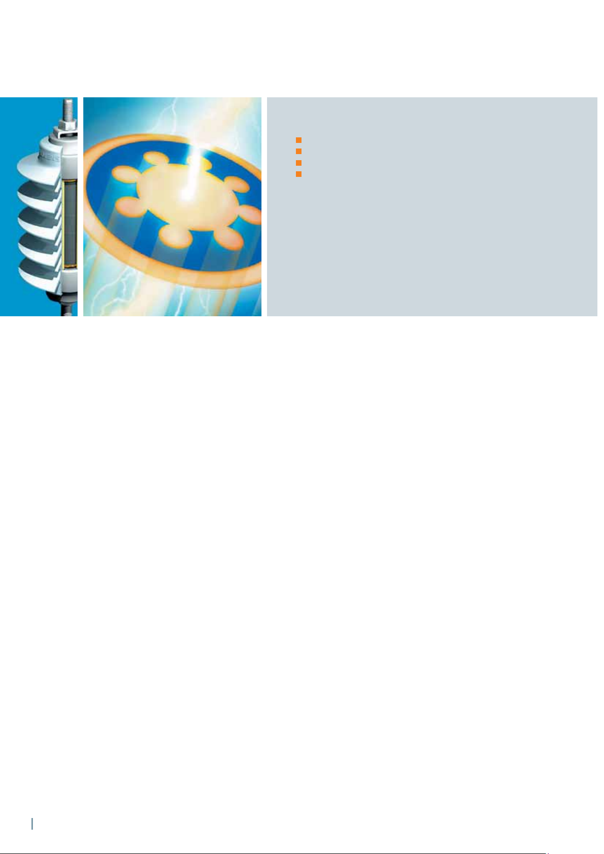
Setting new Standards
The 3EK7‘s mechanical features:
Glass-collared MOV,
Silicone rubber housing,
FRP rods and
Aluminium end fi ttings.
Three types of 3EK7 surge arresters are available:
3EK7…-. C .. surge arresters according to IEC 60099-4
with metric thread,
3EK7...-. A .. surge arresters according to IEEE Std C 62.11
with imperial thread.
For special applications:
3EK7...-. B .. surge arresters according to IEEE Std C 62.11
with metric thread.
The new 3EK7 surge arrester from Siemens offers superior
protection against power surges for the equipment in
electrical distribution systems with operating voltages
of up to 72.5 kV. Besides being highly resistant to
environmental pollution of all kinds, its performance in
dealing with earth faults and its excellent short-circuit
ratings are setting entirely new standards. The silicone
on the new 3EK7 surge arrester refuses to allow any
deposits of pollution or fi lms of moisture to form on it.
Thus, surface currents caused by pollution will virtually
not occur. The 3EK7 arrester is also very lightweight,
robust and durable, due to its special cage design.
2
Page 3
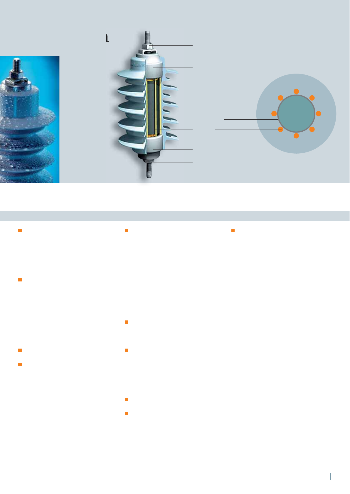
3EK7 Design
3
M12 or
Nut, washer
Clamp
End fi tting
Silicone housing,
directly molded
Metal oxide varistor MOV
Glass coating
FRP rods
End fi tting
Nut, washer
M12 or
8
/
inch stainless steel stud
3
8
/
inch stainless steel stud
3EK7 a top quality product
The silicone rubber (SR) housing is
molded directly onto the MOV blocks
and the protection cage. It provides an
excellent sealing system against
moisture ingress and partial discharges.
In addition, the MOV blocks are
glass-collared to prevent aging.
Highest quality materials. SR is highly
hydrophobic and maintains this ability
to repel water and any deposits of
pollution throughout its entire service
life. This results in high tracking and
erosion resistance. Furthermore, the
SR housing is self-extinguishing and
fl ame-retardant. These advantages
provide maintenance free and reliable
service life for 3EK7 arresters.
Manufacturing plants are certifi ed
under ISO 9001 and ISO 14001.
3EK7 arresters have been type tested
by an independent test laboratory.
Secure and reliable design
The 3EK7 series is based on a cage
of pre-stressed fi ber-reinforced plastic
rods for high mechanical strength,
reducing the risk of internal components
being ejected. In the extremely rare
event of the resistors being overloaded,
arcing cannot result in a build-up of
critical internal pressure, since the
resistors are not enclosed in a sealed
mechanical shell. Thus, the arc can
escape through the silicone sheath,
leaving the mechanical support
structure of the enclosure unharmed.
The cage is lightweight design and yet
it offers excellent torsional, tensile and
cantilever strength: Maximum working
cantilever strength of 350 Nm.
SR is resistant to UV and ozone exposure
as well as to all common organic and
non-organic solvents and cleaning
agents. Therefore, the 3EK7 is suitable
for any environmental conditions of
industrial areas as well as in desert or
coastal regions.
3EK7 arresters are suitable for a
temperature range from –55° C to +50° C.
Application altitude up to
3600 m a.s.l.
Fast delivery
Flexibility in production and in our
global network of service and sales
facilities provide fast and prompt
supply e. g. shipment ex stocks within
six days after your order has been
received for the surge arresters marked
with asterisk (*) (Refer to table on
page 4 and 6).
3
Page 4
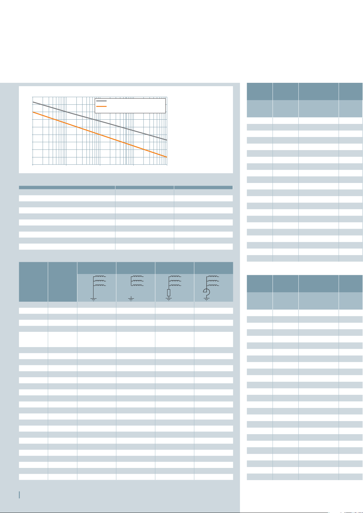
3EK7 Arresters According to IEC 60099-4
Selection and Main Data
Voltage per unit U
1.25
1.2
1.15
1.1
1.05
1
0.95
0.9
0.85
0.8
0.1 1 10 100 1000
r
Preheating to 40° C
Preheating to 60° C and stressing
with rated energy
Time in seconds
Table 1: IEC power-frequency voltage versus time characteristic
Nominal discharge current I
Maximum continous operating voltage U
Rated voltage U
Long duration current impulse 150 A 325 A
High current pressure relief 20 kA 20 kA
Low current pressure relief 600 A 600 A
High-current impulse 65 kA 100 kA
Maximum permisible static service load 280 Nm 350 Nm
Maximum permisible service load (MPSL) 400 Nm 500 Nm
Energy absorption capability 2.2 kJ/kV U
r
n
c
5 kA 10 kA
48 kV 48 kV
60 kV 60 kV
r
3.5 kJ/kV U
Table 2: 3EK7 arrester main data
Highest
voltage
for
equipment
U
m
[kV]
2.75 30; 45; 60 3EK7 030-.C.. 3EK7 050-.C.. 3EK7 030-.C.. 3EK7 050-.C..
3.6 20; 40 3EK7 030-.C.. 3EK7 050-.C.. 3EK7 030-.C.. 3EK7 050-.C..
5.5 45; 60; 75 3EK7 050-.C.. 3EK7 090-.C.. 3EK7 060-.C.. 3EK7 090-.C..
7.2 40; 60 3EK7 060-.C.. 3EK7 090-.C.. 3EK7 090-.C.. 3EK7 090-.C..
8.25 60; 75; 95 3EK7 090-.C.. 3EK7 105-.C.. 3EK7 090-.C.. 3EK7 105-.C..
12 60; 75; 95
15.5 75 3EK7 120-.C.. - 3EK7 150-.C.. -
15.5 85; 110 3EK7 120-.C.. 3EK7 210-.C.. 3EK7 150-.C.. 3EK7 210-.C..
17.5 75 3EK7 150-.C.. - 3EK7 180-.C.. -
17.5 95 3EK7 150-.C.. 3EK7 220-.C.. 3EK7 180-.C.. 3EK7 220-.C..
24 95 3EK7 210-.C.. - 3EK7 240-.C.. -
24 125; 145 3EK7 210-.C.. 3EK7 300-.C.. 3EK7 240-.C.. 3EK7 300-.C..
25 125; 145 3EK7 210-.C.. 3EK7 315-.C.. 3EK7 250-.C.. 3EK7 315-.C..
27 95 3EK7 210-.C.. - - -
27 125 3EK7 210-.C.. - 3EK7 270-.C.. -
27 150 3EK7 210-.C.. 3EK7 360-.C.. 3EK7 270-.C.. 3EK7 360-.C..
30 160 3EK7 240-.C.. 3EK7 390-.C.. 3EK7 300-.C.. 3EK7 390-.C..
36 145 3EK7 300-.C.. - 3EK7 360-.C.. -
36 170 3EK7 300-.C.. 3EK7 450-.C.. 3EK7 360-.C.. 3EK7 450-.C..
38 125 3EK7 300-.C.. - - -
38 150 3EK7 300-.C.. - 3EK7 390-.C.. -
38 200 3EK7 300-.C.. 3EK7 480-.C.. 3EK7 390-.C.. 3EK7 480-.C..
40.5 190 3EK7 315-.C.. 3EK7 510-.C.. 3EK7 420-.C.. 3EK7 510-.C..
48.3 150 3EK7 390-.C.. - - -
48.3 200 3EK7 390-.C.. - 3EK7 480-.C.. -
48.3 250 3EK7 390-.C.. 3EK7 600-.C.. 3EK7 480-.C.. 3EK7 600-.C..
52 250 3EK7 420-.C.. - 3EK7 540-.C.. -
72.5 325 3EK7 570-.C.. - - -
Rated
lightning
impulse
withstand
voltage
[kV]
Solidly earthed
neutral system
3EK7 090-.C..
or
3EK7 105-.C..
Isolated neutral
system
3EK7 150-.C.. 3EK7 120-.C.. 3EK7 150-.C..
Impedance earthed
neutral system
Resonant earthed
neutral system
Table 3: Typical 3EK7 arresters for system voltages according to IEC 60099-4
4
Rated
voltage U
[kV] [kV]
10.5* 8.4 3EK7 105 -2CB4 24.4
12* 9.6 3EK7 120 -2CC4 27.8
15* 12 3EK7 150 -2CC4 34.7
21* 16.8 3EK7 210 -2CD4 48.6
31.5 25.2 3EK7 315 -2CH4 72.9
r
Continuous
operating
r
voltage U
3 2.4 3EK7 030 -2CB4 7.0
6 4.8 3EK7 060 -2CB4 14.0
9* 7.2 3EK7 090 -2CB4 20.9
18 14.4 3EK7 180 -2CD4 41.7
24 19.2 3EK7 240 -2CE4 55.5
27 21.6 3EK7 270 -2CF4 62.6
30 24 3EK7 300 -2CF4 69.3
33 26.4 3EK7 330 -2CH4 76.4
36 28.8 3EK7 360 -2CH4 83.3
39 31.2 3EK7 390 -2CH4 90.5
42 33.6 3EK7 420 -2CH4 97.4
45 36 3EK7 450 -2CH4 104
48 38.5 3EK7 480 -2CK4 111
51 41 3EK7 510 -2CK4 118
54 43.2 3EK7 540 -2CK4 125
57 45.6 3EK7 570 -2CK4 132
60 48 3EK7 600 -2CK4 139
c
Arrester
part number
1 kA
8/20 µs
[kV cr]
Table 4: 3EK7 nominal discharge current 5 kA
Rated
voltage U
[kV] [kV]
10.5* 8.4 3EK7 105 -4CB4 22.8
12* 9.6 3EK7 120 -4CC4 25.9
15* 12 3EK7 150 -4CC4 32.3
18* 14.4 3EK7 180 -4CD4 38.8
21* 16.8 3EK7 210 -4CD4 45.3
22* 17.6 3EK7 220 -4CE4 47.5
24* 19.2 3EK7 240 -4CE4 51.7
30* 24 3EK7 300 -4CF4 64.6
31.5 25.2 3EK7 315 -4CH4 67.9
36* 28.8 3EK7 360 -4CH4 77.6
50.5* 40.5 3EK7 505 -4CK4 107
Continuous
operating
r
voltage U
3 2.4 3EK7 030 -4CB4 6.6
5 4 3EK7 050 -4CB4 10.8
6 4.8 3EK7 060 -4CB4 13.0
9* 7.2 3EK7 090 -4CB4 19.4
25 20 3EK7 250 -4CE4 53.9
27 21.6 3EK7 270 -4CF4 58.2
33 26.4 3EK7 330 -4CH4 71.1
39 31.2 3EK7 390 -4CH4 84.2
42 33.6 3EK7 420 -4CH4 90.7
45 36 3EK7 450 -4CH4 97.2
48 38.5 3EK7 480 -4CK4 104
51 41 3EK7 510 -4CK4 110
54 43.2 3EK7 540 -4CK4 117
57 45.6 3EK7 570 -4CK4 123
60 48 3EK7 600 -4CK4 130
c
Arrester
part number
1 kA
8/20 µs
[kV cr]
Table 5: 3EK7 nominal discharge current 10 kA
Page 5

Lightning
impulse
withstand
voltage
Height
“H”
Net
1)
weight
Packed
weight
Pallet
weight
Qty. per
3 kA
8/20 µs
[kV cr]
Maximum discharge voltage
5 kA
8/20 µs
[kV cr]
10 kA
8/20 µs
[kV cr]
15 kA
8/20 µs
[kV cr]
20 kA
8/20 µs
[kV cr]
125 A
30/60 µs
[kV cr]
Creepage
distance
Flashover
distance
500 A
30/60 µs
[kV cr] [mm] [mm] [kV] [mm] [kg] [kg] [kg] [pcs]
7.7 8.1 8.8 9.6 10.4 6.2 6.6 372 180 104 170 1.5 2.1 488 221
15.3 16.1 17.5 19.0 20.6 12.2 13.2 372 180 104 170 1.5 2.1 488 221
22.8 24.0 26.2 28.3 30.7 18.2 19.7 372 180 104 170 1.6 2.2 510 221
26.7 28.1 30.6 33.2 36.0 21.4 23.0 372 180 104 170 1.6 2.2 510 221
30.4 32.0 34.9 37.8 41.0 24.3 26.2 485 210 122 200 1.8 2.4 494 195
37.9 39.9 43.5 47.1 51.1 30.3 32.7 485 210 122 200 1.9 2.5 514 195
45.5 47.9 52.2 56.5 61.3 36.4 39.3 605 248 144 240 2.2 2.8 506 169
53.1 55.9 60.9 66.0 71.6 42.5 45.8 605 248 144 240 2.3 2.9 523 169
60.6 63.8 69.5 75.3 81.7 48.5 52.3 775 286 166 270 2.6 3.3 535 156
68.3 71.9 78.4 84.8 92.0 54.6 59.0 900 318 184 300 2.9 3.6 491 130
75.7 79.7 86.9 94.0 102 60.6 65.4 900 318 184 300 2.9 3.6 491 130
79.6 83.8 91.3 98.9 107 63.7 68.7 1230 418 242 400 3.7 4.4 545 117
83.4 87.8 95.7 104 112 66.7 72.0 1230 418 242 400 3.7 4.4 545 117
91.0 95.8 104 113 123 72.8 78.6 1230 418 242 400 3.8 4.5 557 117
98.8 104 113 123 133 79.0 85.3 1230 418 242 400 3.8 4.5 557 117
106 112 122 132 143 85.1 91.8 1230 418 242 400 3.9 4.6 569 117
114 120 131 142 154 91.2 98.4 1230 418 242 400 3.9 4.6 569 117
122 128 140 151 164 97.3 105 1595 520 302 510 4.8 5.6 464 78
129 136 148 161 174 103 112 1595 520 302 510 4.8 5.6 464 78
137 144 157 170 184 109 118 1595 520 302 510 4.9 5.7 471 78
144 152 166 179 195 116 125 1595 520 302 510 4.9 5.7 471 78
152 160 174 189 205 122 131 1595 520 302 510 5.0 5.8 479 78
pallet
Lightning
impulse
withstand
voltage
Height
“H”
Net
1)
weight
Packed
weight
Pallet
weight
Qty. per
3 kA
8/20 µs
[kV cr]
Maximum discharge voltage
5 kA
8/20 µs
[kV cr]
10 kA
8/20 µs
[kV cr]
15 kA
8/20 µs
[kV cr]
20 kA
8/20 µs
[kV cr]
125 A
30/60 µs
[kV cr]
Creepage
distance
Flashover
distance
500 A
30/60 µs
[kV cr] [mm] [mm] [kV] [mm] [kg] [kg] [kg] [pcs]
7.1 7.5 8.1 8.7 9.3 5.8 6.2 372 180 104 170 1.5 2.1 488 221
11.7 12.4 13.3 14.4 15.3 9.4 10.1 372 180 104 170 1.6 2.2 510 221
14.2 15.0 16.1 17.4 18.5 11.4 12.2 372 180 104 170 1.6 2.2 510 221
21.1 22.3 24.0 25.9 27.6 17.0 18.2 372 180 104 170 1.7 2.3 532 221
24.7 26.1 28.1 30.3 34.6 20.0 22.7 372 180 104 170 1.7 2.3 532 221
28.2 29.8 32.0 34.6 36.8 22.7 24.3 485 210 122 200 2.0 2.6 533 195
35.1 37.1 39.9 43.1 45.9 28.3 30.3 485 210 122 200 2.1 2.7 553 195
42.2 44.5 47.9 51.7 55.1 34.0 36.4 605 248 144 240 2.4 3.0 540 169
49.2 52.0 55.9 60.4 64.3 39.7 42.5 605 248 144 240 2.5 3.1 557 169
51.6 54.5 58.6 63.3 67.4 41.6 44.5 775 286 166 270 2.8 3.5 566 156
56.1 59.3 63.8 68.9 73.4 45.3 48.5 775 286 166 270 2.8 3.5 566 156
58.5 61.8 66.5 71.8 76.5 47.2 50.5 775 286 166 270 2.9 3.6 581 156
63.3 66.9 71.9 77.7 82.7 51.0 54.6 775 318 184 300 3.2 3.9 530 130
70.1 74.1 79.7 86.1 91.7 56.6 60.6 775 318 184 300 3.2 3.9 530 130
73.7 77.9 83.8 90.5 96.4 59.5 63.7 1230 418 242 400 4.0 4.7 581 117
77.3 81.7 87.8 94.8 101 62.3 66.7 1230 418 242 400 4.1 4.8 592 117
84.3 89.1 95.8 104 110 68.0 72.8 1230 418 242 400 4.1 4.8 592 117
91.5 96.7 104 112 120 73.8 79.0 1230 418 242 400 4.2 4.9 604 117
98.6 104 112 121 129 79.5 85.1 1230 418 242 400 4.3 5.0 616 117
106 112 120 130 138 85.2 91.2 1230 418 242 400 4.4 5.1 627 117
113 119 128 138 147 90.9 97.3 1595 520 302 510 5.2 6.0 495 78
116 123 132 143 152 93.7 100 1595 520 302 510 5.3 6.1 503 78
120 127 136 147 156 96.6 103 1595 520 302 510 5.3 6.1 503 78
127 134 144 156 166 102 109 1595 520 302 510 5.4 6.2 510 78
134 141 152 164 175 108 116 1595 520 302 510 5.5 6.3 518 78
141 149 160 173 184 114 122 1595 520 302 510 5.6 6.4 526 78
1) Refer to fi gure 1 on page 8 (*) Available ex stock
pallet
5
Page 6

3EK7 Arresters According to IEEE Std C 62.11
Selection and Main Data
Voltage per unit MCOV
1.9
1.8
1.7
1.6
1.5
1.4
1.3
1.2
1.1
1
0.01 0.1 1 10 100 1000 10000
3EK7 heavy duty
3EK7 riser pole
Time in seconds
Table 6: ANSI temporary overvoltage, preheating 60˚ C, no prior duty
Normal duty Heavy duty Riser pole
Maximum continous operating voltage MCOV 29 kV 29 kV 29 kV
Duty cycle voltage 36 kV 36 kV 36 kV
Low-current, long-duration 75 A 250 A 250 A
High current pressure relief 20 kA 20 kA 20 kA
Low current pressure relief 600 A 600 A 600 A
High-current, short-duration 65 kA 100 kA 100 kA
Coordinating current 5 kA 10 kA 10 kA
Maximum design cantilever load-static (MDCL) 280 Nm 280 Nm 280 Nm
Energy absorption capability 2.7 kJ/kV MCOV 4.6 kJ/kV MCOV 4.6 kJ/kV MCOV
Table 7: 3EK7 distribution arrester main data
System L-L Voltage
[kV]
2.4 3EK7 030-.A..
4.16 3EK7
4.26 3EK7
4.8 3EK7
6.9 3EK7
8.3 3EK7
12 3EK7
12.47
13.2 3EK7
13.8
20.78 3EK7 150-.A.. 3EK7 210-.A..
22.86 3EK7
23 3EK7
24.94 3EK7
27.6 3EK7
34.5 3EK7
Four-wire
multigrounded
neutral wye
030-.A.. 3EK7 060-.A.. 3EK7 060-.A..
060-.A.. 3EK7 090-.A..
090-.A.. 3EK7 120-.A..
3EK7
090-.A..
or
100-.A..
3EK7
100-.A.. 3EK7 150-.A..
100-.A..
3EK7
or
3EK7 120-.A..
150-.A.. 3EK7 210-.A..
180-.A.. 3EK7 270-.A..
210-.A.. 3EK7 300-.A..
270-.A.. 3EK7 360-.A..
Three-wire
low impedance
grounded neutral circuit
3EK7
150-.A..
3EK7
150-.A.. 3EK7 180-.A..
Three-wire
high impedance
grounded neutral circuit
Table 8: Typical 3EK7 arresters for system voltages
according to the latest IEEE Std C 62.11
6
060-.A..
060-.A..
090-.A..
300-.A..
Duty
MCOV
cycle
[kV] [kV]
3 2.55 3EK7 030 -2AB4 10.0 8.2
6 5.1 3EK7 060 -2AB4 20.0 16.3
9* 7.65 3EK7 090 -2AB4 30.0 24.5
10* 8.4 3EK7 100 -2AB4 33.3 27.2
12 10.2 3EK7 120 -2AC4 38.8 31.7
15 12.7 3EK7 150 -2AC4 48.4 39.6
18* 15.3 3EK7 180 -2AD4 57.2 46.8
21 17 3EK7 210 -2AD4 66.8 54.6
24 19.5 3EK7 240 -2AE4 73.9 60.4
27* 22 3EK7 270 -2AF4 83.1 68.0
30 24.4 3EK7 300 -2AF4 92.3 75.6
33 27.5 3EK7 330 -2AH4 102 83.1
36 29 3EK7 360 -2AH4 111 90.7
Arrester part
number
FOW
[kV cr]
Table 9: 3EK7 normal duty
Duty
MCOV
cycle
[kV] [kV]
3* 2.55 3EK7 030 -3AB4 10.5 8.0
6* 5.1 3EK7 060 -3AB4 21.6 16.5
9* 7.65 3EK7 090 -3AB4 30.9 23.6
10* 8.4 3EK7100 -3AB4 32.3 24.7
12 10.2 3EK7120 -3AC4 41.0 31.3
15* 12.7 3EK7 150 -3AD4 51.3 39.1
18* 15.3 3EK7 180 -3AD4 61.5 47.0
21* 17 3EK7 210 -3AE4 67.3 51.4
24 19.5 3EK7 240 -3AF4 77.6 59.2
27* 22 3EK7 270 -3AF4 87.7 66.9
30* 24.4 3EK7 300 -3AH4 96.6 73.8
33 27.5 3EK7 330 -3AH4 108 82.7
36 29 3EK7 360 -3AH4 119 90.6
Arrester part
number
FOW
[kV cr]
Table 10: 3EK7 heavy duty
Duty
MCOV
cycle
[kV] [kV]
3 2.55
6 5.1
9* 7.65
10* 8.4
12 10.2
15 12.7
18* 15.3 3EK7 180 -4AE4 52.7 40.2
21 17
24 19.5
27* 22
30 24.4
33 27.5
36 29
Arrester part
number
3EK7 030 -4AB4
3EK7 060 -4AB4
3EK7 090 -4AB4
3EK7 100 -4AC4
3EK7 120 -4AD4
3EK7 150 -4AD4
3EK7 210 -4AF4
3EK7 240 -4AH4
3EK7 270 -4AH4
3EK7 300 -4AH4
3EK7 330 -4AK4
3EK7 360 -4AK4
FOW
[kV cr]
8.9 6.8
17.7 13.5
26.4 20.2
29.3 22.3
35.2 26.9
43.9 33.5
61.5 47.0
70.2 53.6
79.1 60.4
87.7 66.9
96.6 73.8
105 80.5
Table 11: 3EK7 riser pole
1.5 kA
8/20 µs
[kV cr]
1.5 kA
8/20 µs
[kV cr]
1.5 kA
8/20 µs
[kV cr]
Page 7

3 kA
8/20 µs
[kV cr]
Maximum discharge voltage
5 kA
8/20 µs
[kV cr]
10 kA
8/20 µs
[kV cr]
20 kA
8/20 µs
[kV cr]
40 kA
8/20 µs
[kV cr]
125 A
45/90 µs
[kV cr]
Creepage
distance
Flashover
distance
Lightning
impulse
withstand
voltage
500 A
45/90 µs
[kV cr] [mm] [mm] [kV] [mm] [kg] [kg] [kg] [pcs]
Height
“H”
Net
1)
weight
Packed
weight
Pallet
weight
Qty. per
8.6 9.1 9.9 11.6 14.0 6.9 7.4 372 180 104 170 1.4 1.6 393 240
17.3 18.2 19.8 23.3 28.0 13.8 14.9 372 180 104 170 1.4 1.6 406 240
25.9 27.2 29.7 34.9 42.0 20.7 22.3 372 180 104 170 1.5 1.7 419 240
28.8 30.3 33.0 38.8 46.6 23.0 24.8 372 180 104 170 1.6 1.7 426 240
33.5 35.2 38.4 45.1 54.3 26.8 28.9 485 210 122 200 1.8 2.0 375 180
41.8 44.0 48.0 56.4 67.8 33.5 36.1 485 210 122 200 1.8 2.1 385 180
49.4 52.0 56.7 66.6 80.1 39.5 42.7 605 248 144 240 2.2 2.4 444 180
57.7 60.7 66.2 77.7 93.5 46.1 49.8 605 248 144 240 2.2 2.4 454 180
63.8 67.2 73.2 86.0 103 51.0 55.1 775 286 166 270 2.5 2.7 510 180
71.8 75.6 82.4 96.7 116 57.4 62.0 900 318 184 300 2.8 3.1 383 120
79.7 83.9 91.5 107 129 63.8 68.8 900 318 184 300 2.9 3.1 390 120
87.7 92.3 101 118 142 70.2 75.7 1230 418 242 400 3.7 3.9 483 120
95.7 101 110 129 155 76.6 82.6 1230 418 242 400 3.7 3.9 489 120
pallet
Lightning
impulse
withstand
voltage
Height
“H”
Net
1)
weight
Packed
weight
Pallet
weight
Qty. per
3 kA
8/20 µs
[kV cr]
Maximum discharge voltage
5 kA
8/20 µs
[kV cr]
10 kA
8/20 µs
[kV cr]
20 kA
8/20 µs
[kV cr]
40 kA
8/20 µs
[kV cr]
125 A
45/90 µs
[kV cr]
Creepage
distance
Flashover
distance
500 A
45/90 µs
[kV cr] [mm] [mm] [kV] [mm] [kg] [kg] [kg] [pcs]
8.4 8.8 9.5 10.9 12.6 6.7 7.2 372 180 104 170 1.5 1.7 412 240
17.2 18.2 19.6 22.5 26.1 13.9 14.9 372 180 104 170 1.6 1.7 433 240
24.7 26.1 28.1 32.3 37.4 20.0 21.4 372 180 104 170 1.7 1.8 451 240
25.9 27.3 29.4 33.8 39.1 20.9 22.3 372 180 104 170 1.7 1.9 462 240
32.8 34.7 37.3 42.9 49.6 26.5 28.3 485 210 122 200 2.0 2.2 408 180
41.0 43.3 46.6 53.6 62.0 33.1 35.4 605 248 144 240 2.4 2.5 472 180
49.2 52.0 55.9 64.3 74.3 39.7 42.5 605 248 144 240 2.5 2.7 497 180
53.9 56.9 61.2 70.4 81.4 43.5 46.5 775 286 166 270 2.8 3.0 559 180
62.0 65.6 70.5 81.1 93.8 50.1 53.6 900 318 184 300 3.1 3.3 417 120
70.1 74.1 79.7 91.7 106 56.6 60.6 900 318 184 300 3.2 3.5 433 120
77.3 81.7 87.8 101 117 62.3 66.7 1230 418 242 400 4.0 4.2 523 120
86.6 91.5 98.4 113 131 69.9 74.8 1230 418 242 400 4.1 4.3 536 120
94.9 100 108 124 143 76.5 81.9 1230 418 242 400 4.2 4.5 556 120
Lightning
impulse
withstand
voltage
Height
“H”
Net
1)
weight
Packed
weight
Pallet
weight
Qty. per
3 kA
8/20 µs
[kV cr]
Maximum discharge voltage
5 kA
8/20 µs
[kV cr]
10 kA
8/20 µs
[kV cr]
8/20 µs
[kV cr]
20 kA
40 kA
8/20 µs
[kV cr]
125 A
45/90 µs
[kV cr]
Creepage
distance
Flashover
distance
500 A
45/90 µs
[kV cr] [mm] [mm] [kV] [mm] [kg] [kg] [kg] [pcs]
7.1 7.5 8.1 9.3 10.8 5.8 6.2 372 180 104 170 1.4 1.7 415 240
14.2 15.0 16.1 18.5 21.4 11.4 12.2 372 180 104 170 1.5 1.8 437 240
21.1 22.3 24.0 27.6 31.9 17.0 18.2 372 180 104 170 1.6 1.8 447 240
23.4 24.7 26.6 30.6 35.4 18.9 20.2 485 210 122 200 1.7 1.8 458 240
28.2 29.8 32.0 36.8 42.6 22.7 24.3 605 248 144 240 1.9 2.1 524 240
35.1 37.1 39.9 45.9 53.1 28.3 30.3 605 248 144 240 2.3 2.5 611 240
42.2 44.5 47.9 55.1 63.7 34.0 36.4 775 286 166 270 2.4 2.7 494 180
49.2 52.0 55.9 64.3 74.3 39.7 42.5 900 318 184 300 2.8 3.0 551 180
56.1 59.3 63.8 73.4 84.9 45.3 48.5 1230 418 242 400 3.0 3.3 413 120
63.3 66.9 71.9 82.7 95.6 51.0 54.6 1230 418 242 400 3.2 3.5 430 120
70.1 74.1 79.7 91.7 106 56.6 60.6 1230 418 242 400 4.0 4.2 522 120
77.3 81.7 87.8 101 117 62.3 66.7 1595 520 302 510 4.2 4.4 544 120
84.3 89.1 95.8 110 127 68.0 72.8 1595 520 302 510 4.3 4.5 555 120
1) Refer to fi gure 1 on page 8; (*) Available ex stock
pallet
pallet
7
Page 8

Drawings and Accessories
23.5
64
∅ 12.5
∅ 45
Figure 2: NEMA insulating bracket for Ur ≤ 21 kV
H*
Order code P12; 0.25 kg
26
52.5
39.5
50.5
171
125 20
∅ 14
38
41
3314
75
M12
or 3/8”
∅ 119
36
Figure 1: 3EK7 surge arrester main dimensions
* please see tables on page 5 or 7
214
173
12
23.5
64
∅ 12.5
52.5
26
256
210 20
Figure 3: NEMA insulating bracket for Ur > 21 kV
Order code P12; 0.4 kg
299
258
39.5
∅ 14
12
41
3314
75
24
Figure 4: DIN insulating bracket for U
Order code P22; 0.85 kg
8
14.5
15
≤ 21 kV
r
26
17
60
24
Figure 5: DIN insulating bracket for Ur > 21 kV
Order code P22; 1 kg
14.5
15
26
17
60
Page 9

14.5
12
∅ 13
16
75
20
Figure 6: L-bracket
Order code M12; 0.1 kg
∅ 13
40
450
33
∅ 13
13
∅ 13
8
263060
197
∅ 14
30
152
15
Figure 7: DIN metal bracket (stainless), Order code P23; 0.6 kg and
DIN metal bracket (hot dip galvanised), Order code P21; 0.6 kg
∅ 14 or 10.2 ∅ 14
50
25
152
202
Figure 8: Insulated ground lead/Insulated line lead
Order code P51/M51; 0.09 kg, 16 mm
221 (8.7”)
145
41 64
57
14.3
434320
2
14
20
18
25
40
Figure 10: Transformer bracket 8.7”
Order code Q11; 0.6 kg
78
Figure 9: NEMA metal bracket (hot dip galvanized)
Order code P11; 0.6 kg
280 (11”)
178
41 64
57
14.3
434320
14
20
Figure 11: Transformer bracket 11”
Order code Q12; 0.7 kg
18
78
25
40
9
Page 10

Drawings and Accessories
310 (12.25”)
178
14
41 63
57
14.3
434320
Figure 12: Transformer bracket 12.25”
Order code Q13; 0.8 kg
73
0…120
220
198
10.5…150
66
71
18
25
40
15.2
78
18
∅ 18
368 (14.5”)
327
46
86 64 86
69
14.3
55 40 40 55
19
54
Figure 13: Transformer bracket 14.5”
Order code Q14; 0.8 kg
∅ 254
∅ 200
3 x 120°
14
18
35
76
14
40
142
227
Figure 14: NEMA X-arm bracket
Order code Q51; 1.3 kg
Figure 16: Line clamp
Order code M11; 0.1 kg
10
cable ∅ 8…∅ 14
cable ∅ 14…∅ 18
253.5
Figure 15: Mounting plate, 37 mm height
Order code Q81; 1.6 kg
∅ 15
57
24.5
∅ 75
Figure 17: Bird protection cap
Order code M81; 50 g
Page 11

45
∅ 12.5
24
4
Figure 18: Stainless steel cap
Order code M71; 5 g
Figure 19: Disconnector
Order code P31; 0.1 kg
Outline drawings for common design options are shown
in fi gure 20, 21 and 22
M12 or 3/8”
Figure 20: 3EK7 surge arrester with
accessories P12 and P31
Figure 21: 3EK7 surge arrester with
accessories P12, P31 and Q51
Figure 22: 3EK7 surge arrester
with accessories P12, P31, P52 and Q11
11
Page 12

Example
Part number
Internal use
Rated voltage in kV x 10
–
Classification
Nominal discharge current In = 5 kA or distribution class, normal duty 2
Distribution class, heavy duty 3
Nominal discharge current In = 10 kA or riser pole 4
Standard
IEEE Std C 62.11 with imperial-thread terminals A
IEEE Std C 62.11 with metric-thread terminals B
IEC - 60099-4 with metric-thread terminals C
Housing size
170 mm B
200 mm C
240 mm D
270 mm E
300 mm F
400 mm H
510 mm K
Internal use 4
3 E K 7 300 – 4 C F 4
3EK7
300
–
Standard equipped at
high voltage terminal M12 or 3/8 inch stud
with clamp, washer and nut
earthing terminal M12 or 3/8 inch stud
with washer and nut
Example
Part number with mounting accessories
For additional parts only*
High-voltage terminal equipped with
Line clamp, washer, nut M11
L-bracket, washer, nut M12
Line lead, insulated, 450 mm/18 inch, 16 mm
Stainless steel cap M71
Bird-protection cap
Earth terminal equipped with
NEMA metal bracket (hot dip galvanized steel) P11
NEMA insulating bracket
DIN metal bracket (hot dip galvanized steel) P21
DIN insulating bracket P22
DIN metal bracket (stainless steel) P23
Disconnector
Ground lead, insulated, 450 mm/18 inch, 16 mm
Mounting auxiliaries
Transformer bracket 8.7 inch Q11
Transformer bracket 11 inch Q12
Transformer bracket 12.25 inch Q13
Transformer bracket 14.5 inch Q14
X-arm bracket Q51
Mounting plate for 200 mm and 10 inch bolt circle
*Other additional parts on request
Not all combinations are possible
2
2
3 E K 7 300 – 4 C F 4 –
Z M51 M81 P12 P31
Z
M51
M81
P12
P31
P51
Q81
Published by
and copyright © 2008:
Siemens AG
Please contact us at:
Phone: +49 (30) 3 86-33 222
E-mail: arrester@siemens.de
Energy Sector
Freyeslebenstrasse 1
91058 Erlangen, Germany
Siemens AG
Energy Sector
Power Transmission Division
High Voltage Products
Nonnendammallee 104
13623 Berlin, Germany
www.siemens.com/arrester-download
www.siemens.com/energy
Power Transmission Division
Order No. E50001-G630-A110-X-4A00
Printed in Germany
Dispo 30000
TH 263-081130 470044 PA 11080.5
Printed on elementary chlorine-free
bleached paper.
All rights reserved.
Trademarks mentioned in this document
are the property of Siemens AG, its
affi liates, or their respective owners.
Subject to change without prior notice.
The information in this document
contains general descriptions of the
technical options available, which
may not apply in all cases. The required
technical options should therefore
be specifi ed in the contract.
 Loading...