

Page 1
SiemensMinderle
3D-TOP Ceiling Stand
Maintenance Instructions
3D-TOP Ceiling Stand
AX
Components
© Siemens, 2003
The protocol RX22-040.832.02.06.02 is required for these
instructions
Print No.:
Replaces: RX22-040.831.02.05.02
03070013030700210307003903074486
RX22-040.831.02.06.02
© Siemens, 2003
All documents may only be used for rendering
services on Siemens Healthcare Products. Any
document in electronic form may be printed
once. Copy and distribution of electronic documents and hardcopies is prohibited. Offenders
will be liable for damages. All other rights are reserved.
English
Doc. Gen. Date: 09.14
n.a.CS PS XP RFU
2003
Page 2

2 Copyright / Version / Disclaimer
1Copyright / Version / Disclaimer
Copyright
“© Siemens, 2003“ refers to the copyright of a Siemens entity such as Siemens Aktiengesellschaft - Germany, Siemens Shenzhen Magnetic Resonance Ltd. - China, Siemens
Shanghai Medical Equipment Ltd. - China, Siemens Medical Solutions USA Inc. - USA,
Siemens Healthcare Diagnostics Inc. - USA and/or Siemens Healthcare Diagnostics Products GmbH - Germany.
Document Version
Siemens reserves the right to change its products and services at any time.
In addition, manuals are subject to change without notice. The hardcopy documents correspond to the version at the time of system delivery and/or printout. Versions to hardcopy
documentation are not automatically distributed. Please contact your local Siemens office
to order current version or refer to our website http://www.healthcare.siemens.com.
Disclaimer
Siemens provides this documentation “as is“ without the assumption of any liability under
any theory of law.
The installation and service of equipment described herein requires superior understanding of our equipment and may only be performed by qualified personnel who are specially
trained for such installation and/or service.
3D-TOP Ceiling Stand RX22-040.831.02.06.02 © Siemens, 2003
09.14 CS PS XP RFU
Page 2 of 34
Page 3

Table of Contents 3
0 Table of Contents
1 _______ Prerequisites / Notes _____________________________________________ 4
Requirements . . . . . . . . . . . . . . . . . . . . . . . . . . . . . . . . . . . . . . . . . . . . . . . . . . . . . . . . . . 4
Notes . . . . . . . . . . . . . . . . . . . . . . . . . . . . . . . . . . . . . . . . . . . . . . . . . . . . . . . . . . . . . . . . 5
Safety Information. . . . . . . . . . . . . . . . . . . . . . . . . . . . . . . . . . . . . . . . . . . . . . . . . . . . 5
Product-specific Remarks . . . . . . . . . . . . . . . . . . . . . . . . . . . . . . . . . . . . . . . . . . . . . . 5
General Remarks . . . . . . . . . . . . . . . . . . . . . . . . . . . . . . . . . . . . . . . . . . . . . . . . . . . . 6
2 _______ General Visual Check ____________________________________________ 9
Visual Check per IEC 62353 . . . . . . . . . . . . . . . . . . . . . . . . . . . . . . . . . . . . . . . . . . . . . . 9
Table of Warning Labels . . . . . . . . . . . . . . . . . . . . . . . . . . . . . . . . . . . . . . . . . . . . . . . . . 10
3 _______ Cleaning the Components _______________________________________ 11
4 _______ 3D TOP Ceiling Stand ___________________________________________ 12
Special Requirements . . . . . . . . . . . . . . . . . . . . . . . . . . . . . . . . . . . . . . . . . . . . . . . . . . 12
Required Documents . . . . . . . . . . . . . . . . . . . . . . . . . . . . . . . . . . . . . . . . . . . . . . . . 12
Required Tools and Measuring Equipment . . . . . . . . . . . . . . . . . . . . . . . . . . . . . . . . 12
Required Aids . . . . . . . . . . . . . . . . . . . . . . . . . . . . . . . . . . . . . . . . . . . . . . . . . . . . . . 12
Product-specific Safety Information . . . . . . . . . . . . . . . . . . . . . . . . . . . . . . . . . . . . . 12
Work Time/Maintenance Interval . . . . . . . . . . . . . . . . . . . . . . . . . . . . . . . . . . . . . . . 13
Parts Subject to Wear. . . . . . . . . . . . . . . . . . . . . . . . . . . . . . . . . . . . . . . . . . . . . . . . 13
Inspection and Maintenance. . . . . . . . . . . . . . . . . . . . . . . . . . . . . . . . . . . . . . . . . . . . . . 14
5 _______ Final Work Steps _______________________________________________ 28
Special Requirements . . . . . . . . . . . . . . . . . . . . . . . . . . . . . . . . . . . . . . . . . . . . . . . . . . 28
Required Documents . . . . . . . . . . . . . . . . . . . . . . . . . . . . . . . . . . . . . . . . . . . . . . . . 28
Required Tools and Measuring Equipment . . . . . . . . . . . . . . . . . . . . . . . . . . . . . . . . 28
Required Aids . . . . . . . . . . . . . . . . . . . . . . . . . . . . . . . . . . . . . . . . . . . . . . . . . . . . . . 28
Required Materials . . . . . . . . . . . . . . . . . . . . . . . . . . . . . . . . . . . . . . . . . . . . . . . . . . 28
Product-specific Safety Information . . . . . . . . . . . . . . . . . . . . . . . . . . . . . . . . . . . . . 28
Work Time/Maintenance Interval . . . . . . . . . . . . . . . . . . . . . . . . . . . . . . . . . . . . . . . 28
Inspection and Maintenance. . . . . . . . . . . . . . . . . . . . . . . . . . . . . . . . . . . . . . . . . . . . . . 29
6 _______ Changes to Previous Version _____________________________________ 32
7 _______ List of Hazard IDs ______________________________________________ 33
© Siemens, 2003 RX22-040.831.02.06.02 3D-TOP Ceiling Stand
09.14 CS PS XP RFU
Page 3 of 34
Page 4

4 Prerequisites / Notes
1-
1 Prerequisites / Notes
1.1 Requirements
NOTE
Required Documents
During maintenance on the product, the work steps in the
certificate must be documented accordingly.
Maintenance is divided into chapters (as a rule, max. 6 hours
for components). Since there can be the same component
more than one in a customer system, the component checkpoints in the certificate are listed accordingly. Each component must then be entered with the Part Number and Serial
Number. There are also "options" in the customer system.
The options must be check marked accordingly in the certificate.
With parts that must be replaced periodically (battery/steel
cables...), the startup date or the last replacement date must
be entered to ensure the ability to track the dates. As a rule,
the date can be found in the User Handbook (Handover Protocol / old Maintenance Certificate).
• Maintenance Protocol
• See also the individual chapters.
3D-TOP Ceiling Stand RX22-040.831.02.06.02 © Siemens, 2003
09.14 CS PS XP RFU
Page 4 of 34
Page 5
Prerequisites / Notes 5
1.2 Notes
1.2.1 Safety Information
1.2.1.1 General Safety Information
When carrying out the work steps and checks, the general safety information contained in
ARTD (General Guidelines for Technical Service) must be observed.
WARNING
1.2.1.2 Product-specific Safety Information
When carrying out the work steps and checks, the product-specific safety information contained in the documents must be observed.
Dangerous X-radiation during checks and adjustment work
steps.
Risk of death or serious bodily injury.
¹ During the check and adjustment work steps that must
be performed with radiation switched on, the mandatory radiation safety measures must be observed.
These check and adjustment work steps are explicitly
labeled on the following pages with the radiation warn-
ing symbol x .
1.2.2 Product-specific Remarks
The illustrations and drawings may differ slightly depending on the actual system.
1.2.2.1 Notes Regarding Maintenance
Damaged or worn parts may be replaced only with original parts. The Inspection and Maintenance Checklists must be filled out and signed by the Maintenance Technician. Repair
work and work steps that are not listed in the checklists must be listed separately.
NOTE
© Siemens, 2003 RX22-040.831.02.06.02 3D-TOP Ceiling Stand
09.14 CS PS XP RFU
Replace damaged parts in discussion with the customer.
Page 5 of 34
Page 6
6 Prerequisites / Notes
1.2.3 General Remarks
1.2.3.1 Maintenance time / interval
The maintenance time and the maintenance interval is listed in each chapter for a component or in the general chapters.
The completion times for cyclical replacement of parts, e.g. cables or spring-loaded mechanisms, etc. are not included in these Maintenance Instructions.
The work time can be viewed only as a reference value, because the time for e.g. cleaning
can vary widely.
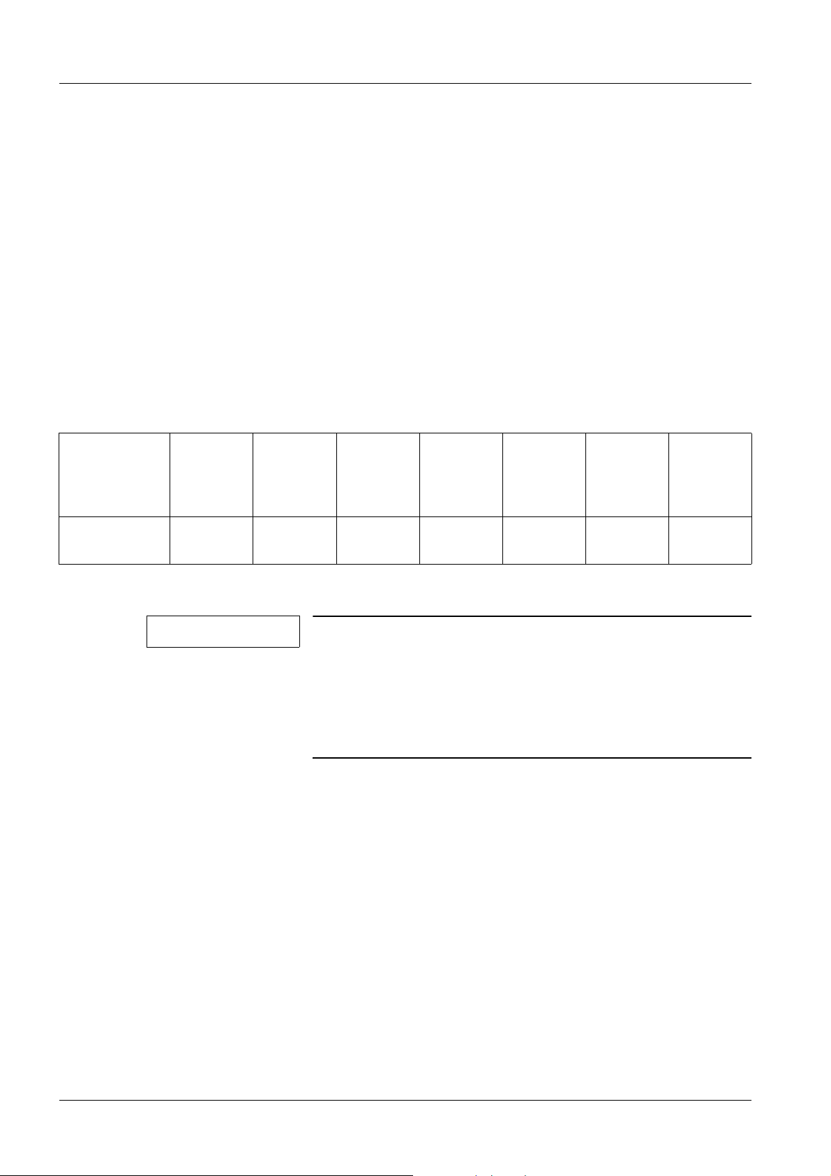
1.2.3.2 Tolerance Data
General tolerances for linear dimensions per ISO 2768
These tolerances apply for all dimensions listed in these instructions as long as no other
tolerance is expressly listed next to the value.
Limit value for
the nominal
range
Adm. toler-
over 3 mm
to 6 mm
over 6 mm
to 30 mm
over
30 mm to
120 mm
±0,5mm ±1mm ±1,5mm ±2,5mm ±4mm ±6mm ±8mm
ance
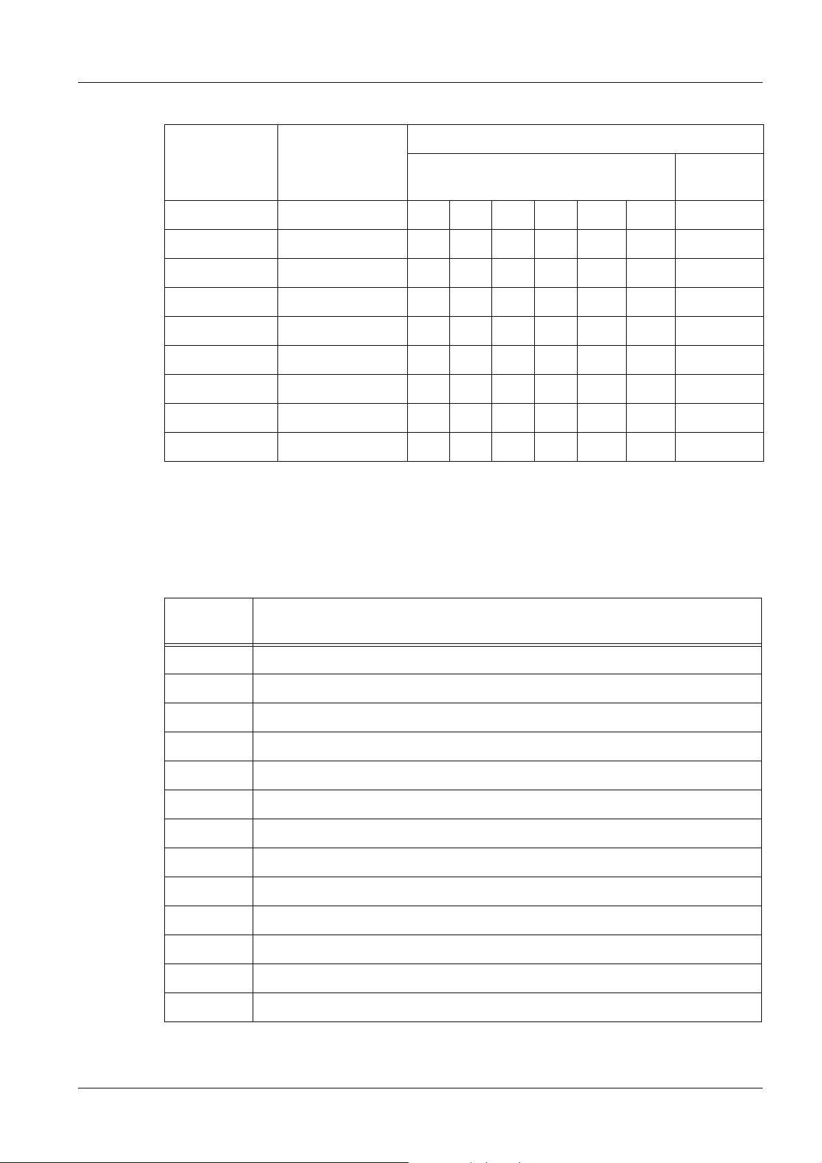
1.2.3.3 Maximum Torque Values in Nm
NOTE
Check the floor mounting.
The torque values for anchor bolts are listed in the Maintenance Instructions (only for the type of anchor bolts included
with the unit).
If the mounting method is different, only "the unit mounting"
can be checked for tightness.
over
120 mm to
400 mm
over
400 mm to
1000 mm
over
1000 mm
to
2000 mm
over
2000 mm
to
4000 mm
3D-TOP Ceiling Stand RX22-040.831.02.06.02 © Siemens, 2003
09.14 CS PS XP RFU
Page 6 of 34
Page 7
Prerequisites / Notes 7
Screw material
Nominal thread
diameter
Hardness rating 4.6 4.8 5.8 8.8 10.9 12.9
M 3 0,5 0,67 0,83 1,3 1,9 2,2 0,62
M 3.5 0,76 1,0 1,3 2,0 2,8 3,4 0,95
M 4 1,1 1,5 1,9 3,0 4,2 5,1 1,4
M 5 2,2 3,0 3,7 6,0 8,4 10,1 2,8
M 6 3,8 5,1 6,4 10,2 14,4 17,3 4,8
M 8 9,5 12,6 15,8 25,3 35,6 42,7 11,9
M 10 18,7 24,8 31,1 49,8 70,0 84,0 23,3
M 12 32,9 43,8 54,8 87,6 123,3 147,9 41,1
Iron/steel per DIN 267
Brass
CuZn alloy
If no other information is provided, use the corresponding torque values for hardness rating
8.8 when checking torque values!
A tolerance of ± 10% is permitted for torque values.
1.2.3.4 Explanation of Abbreviations in the Maintenance Certificate
Abbreviation
SI Safety Inspection
SIE Electrical Safety
SIM Mechanical Safety
PM Preventive Maintenance
PMP Periodic Preventive Maintenance
PMA Maintenance, Preventive Adjustments
PMF Preventive Check of Operating Values and of Functions
Q System Quality, Image Quality
Explanation
QIQ Image Quality
QSQ System Quality
SW Software Maintenance
CSE Customer Service Engineer
IVK Installed Volume Component
© Siemens, 2003 RX22-040.831.02.06.02 3D-TOP Ceiling Stand
09.14 CS PS XP RFU
Page 7 of 34
Page 8

8 Prerequisites / Notes
Abbreviation
MU Maintenance Unit
ROI Region of interest
1.2.3.5 DHHS Regulations
This document does not replace the DHHS Maintenance Instructions “Maintenance
Instructions/Measurement Certificate” in countries with DHHS Regulations.
Explanation
3D-TOP Ceiling Stand RX22-040.831.02.06.02 © Siemens, 2003
09.14 CS PS XP RFU
Page 8 of 34
Page 9

General Visual Check 9
2-
2 General Visual Check
2.1 Visual Check per IEC 62353
SI Checking the cover panels
• All required cover panels present.
- Check the cover panels for visible damage, sharp edges or cracks.
SI Required operator documents present
• Are the required operator documents complete, present, legible?
- In new systems, there is a list with the documents that are shipped in the System
Binder.
- Based on this list, completeness can be checked easily.
- The following always applies: All user instructions, supplements and safety notes
required for use of the system must be present.
SI Checking the Cables, Corrugated Hoses
• The cables (corrugated hoses) may not have any cracks in the insulation.
• Check the corresponding strain reliefs or cable shielding connections.
- The check refers only to laid cables that are visible and to the way in which they are
laid!
SI Check the cable corrugated hoses (of mobile components).
• Check the way in which cables are laid (corrugated hoses) to mobile components.
- The cables should not pose a risk of tripping and should not be laid over any sharp
edges.
- The check refers only to laid cables that are visible and to the way in which they are
laid!
SI Checking the radiation protective panels
• To the extent configured, visually check the following radiation safety panels for cracks
or other damage:
- Radiation protection cover panels
- Lead rubber flaps
- Ceiling-mounted radiation shield
- Any additional radiation shields that can be installed
- Movable radiation shield
SI Checking warning labels
• All warning labels that reference a hazard to the user, patient or the unit through use of
the system must be present.
- e.g: Crushing of fingers, crushing of feet, laser, maximum load, collision warnings.
© Siemens, 2003 RX22-040.831.02.06.02 3D-TOP Ceiling Stand
09.14 CS PS XP RFU
Page 9 of 34
Page 10

10 General Visual Check
2.2 Table of Warning Labels
• No warning labels present.
3D-TOP Ceiling Stand RX22-040.831.02.06.02 © Siemens, 2003
09.14 CS PS XP RFU
Page 10 of 34
Page 11

Cleaning the Components 11
3-
3 Cleaning the Components
Required Tools, Test Equipment and Aids
• Anti-static Vacuum Cleaner n.a.
• Lint-free cleaning cloths n.a.
• Brush to apply grease n.a.
• Brush to remove dust n.a.
• Cleaning agents for plastic, glass and painted parts
e.g. Hakapur concentrated cleaner (500 g), 96 60 648 RH999
• cleaning agent and rust protection for rails
e.g. WD40 contact spray (spray can, 400 g), 28 70 061
• Alcohol n.a.
• Ethyl alcohol, 96% to clean the monitor screen n.a.
Cleaning and General Remarks
NOTE
Depending on the component, observe the applicable points.
PM Inspection of internal heat dissipation
• Clean all ventilation grids.
• Check all fans for function.
PM Cleaning
• Remove dust that has collected inside of the particular components.
• Remove soiling that is not accessible to the customer's cleaning personnel during main-
tenance work.
NOTE
For hygienic reasons, wear rubber gloves while cleaning.
- Soften contrast medium with water only and remove it.
- After completing maintenance work, remove soiling from enameled and anodized
parts with WD40 contact spray, enamel cleaning agent or Hakapur.
© Siemens, 2003 RX22-040.831.02.06.02 3D-TOP Ceiling Stand
09.14 CS PS XP RFU
Page 11 of 34
Page 12

12 3D TOP Ceiling Stand
4-
4 3D TOP Ceiling Stand
4.1 Special Requirements
4.1.1 Required Documents
• Replacement Instructions
4.1.2 Required Tools and Measuring Equipment
• Step ladder n.a.
• Work gloves
Protection against splits in the steel cables
• Torque wrench, 2 Nm to 20 Nm (1/4" drive) 70 59 975
• Torque wrench, 20 Nm to 100 Nm (3/8" drive) 44 30 906
• Torque wrench attachment 56 60 852
• Set of Allen wrenches with ball end (4, 5, 6, 8, 10 mm) (3/8" drive) 81 59 980
• 8 mm Allen wrench (1/2" drive), without ball end 52 66 531
• Spring balance, 100N 44 29 122
• Spring balance, 200N 44 15 113
4.1.3 Required Aids
• Cleaning agents and rust protection for rails
e.g. WD40 contact spray (spray can, 400 g), 28 70 061
• Longtime PD2 (20 g tube) for bearing cages, open ball bearings,
pinion gears ...
n.a.
34 91 271
• Viscogen KL 300 (50 ml tube) for steel cables and chains 72 79 107
Paints (to touch up chips/scratches in the paint finish)
• White (spray can) 84 27 734
• White textured (paint stick) 34 44 403
4.1.4 Product-specific Safety Information
• n.a.
3D-TOP Ceiling Stand RX22-040.831.02.06.02 © Siemens, 2003
09.14 CS PS XP RFU
Page 12 of 34
Page 13

3D TOP Ceiling Stand 13
4.1.5 Work Time/Maintenance Interval
• 2 hours / 12 months
4.1.6 Parts Subject to Wear
Component Name Quan-
tity
Spring-loaded
3D TOP ceiling stand
Mechanism with
built-in Cables
E-TL steel cable
set
Brake lining 2 30 70 815 G6019 X
1 49 53 931 X X
1
Part No. Cyclical
replacement after
10 years
30 71 219 G6019
Replaced
when
damaged
X
© Siemens, 2003 RX22-040.831.02.06.02 3D-TOP Ceiling Stand
09.14 CS PS XP RFU
Page 13 of 34
Page 14

14 3D TOP Ceiling Stand
4.2 Inspection and Maintenance
PM Cleaning
See (Cleaning the Components / p. 11).
SIM Longitudinal Bridge / Checking the Condition and Installation
2
3
1
6
Fig. 1: Longitudinal bridge
T • Longitudinal rail ceiling mounting (M10 Allen screws). 50 Nm
5
4
NOTE
For the screws that are not accessible because of the pinion
rack, the “torque wrench attachement, 5660852” absolutely
must be used. Otherwise, the screw heads can be damaged.
• Checking the pinion rack.
NOTE
T • Check the switch strike plate clamping screws (6/Fig.1/p.14) for the S42/43 safety
limit switches (M4 Allen screw) for tightness.
This check is required only during the 1st maintenance. The
documentation applies as proof of securing with Loctite! The
the pinion rack mount should be secured with Loctite when
installed the first time. In this case, NO check is required. For
the check, remove one screw to determine whether LOCTITE
has been used; then reinsert the screw with LOCTITE. If LOCTITE was not used, apply LOCTITE to all screws on the pinion
rack.
• End stops and rubber bumpers (4/Fig.1/p.14).
3D-TOP Ceiling Stand RX22-040.831.02.06.02 © Siemens, 2003
09.14 CS PS XP RFU
Page 14 of 34
Page 15

3D TOP Ceiling Stand 15
T • Check the M6 or M8 set screws (5/Fig.1/p.14) in the longitudinal and transverse stop
detents for tightness. With an M6 set screw 6.5 Nm, with an M8 set screw 16 Nm.
SIM Check to ensure the roller bearing on the transverse carriage is secured.
NOTE
The roller bearings are secured with mounting screws that
have been tightened to a specified torque. If the spacer
sleeves are not yet installed on a ceiling stand, they absolutely need be installed afterward.
• If spacer sleeves are placed over the roller bearing shafts, the torque no longer needs
to be checked.
• If no spacer sleeves are installed:
T - then the M8 set screws (1/Fig.2/p.15) that secure the roller bearings must be
checked 16 Nm
- and the installation kit with Material No. 87 73 681, "Installation Kit, Split Collar for
Rollers" (spacer sleeves) will need to be installed.
1
2
Fig. 2: Mount
© Siemens, 2003 RX22-040.831.02.06.02 3D-TOP Ceiling Stand
09.14 CS PS XP RFU
Page 15 of 34
Page 16

16 3D TOP Ceiling Stand
SIM M4 Transverse Bridge / Checking Installation
• Check the roller bearings and lateral guide bearings (2/Fig.2/p.15).
T
2
3
1
Fig. 3: Checking mounting
• Check the mounting points for the cable guides.
• Check the stops and rubber bumpers (3/Fig.3/p.16).
• Check the M6 or M8 set screws (2/Fig.3/p.16) for the transverse SID stop detents for
tightness. With an M6 set screw 6.5 Nm, with an M8 set screw 16 Nm.
T
• Tomo drive mounting (two M8 Allen screws). 25 Nm
• Check the tomo drive cover panels.
• Check the installation parts.
PMA Checking the brake assembly, brake lining
1
Fig. 4: Brake assembly
3D-TOP Ceiling Stand RX22-040.831.02.06.02 © Siemens, 2003
09.14 CS PS XP RFU
Page 16 of 34
Page 17

3D TOP Ceiling Stand 17
• Check the condition of the brake lining (1/Fig.4/p.16).
• Check the mounting screws for tightness.
SIE Check the S42/S43 safety limit switches (only with the tomo option).
• Check the function of the safety limit switches.
Fig. 5:
• Select tomo.
• Move into the S42/S43 switches
- The switches must positively actuate.
- The safety breaker audibly deenergizes and the red lamp on the left side of the table
(safety circuit) must go on.
Tomo Drive
© Siemens, 2003 RX22-040.831.02.06.02 3D-TOP Ceiling Stand
09.14 CS PS XP RFU
Page 17 of 34
Page 18

18 3D TOP Ceiling Stand
Fig. 6:
• Check the spacing of the pinion gear to the pinion rack (per the Adjustment Instruc-
tions).
• Check the function of the lift magnets.
SIM Check to ensure the roller bearing on the telescope carriage is secured.
1
Fig. 7: Checking mounting
NOTE
The roller bearings are secured with mounting screws that
have been tightened to a specified torque. If the spacer
sleeves are not yet installed on a ceiling stand, they absolutely need be installed afterward.
• If spacer sleeves are placed over the roller bearing shafts, the torque no longer needs
to be checked.
3D-TOP Ceiling Stand RX22-040.831.02.06.02 © Siemens, 2003
09.14 CS PS XP RFU
Page 18 of 34
Page 19

3D TOP Ceiling Stand 19
• If no spacer sleeves are installed:
T - then the M8 set screws (1/Fig.7/p.18) that secure the roller bearings must be
checked 13 Nm
- and the installation kit with Material No. 87 73 681, "Installation Kit, Split Collar for
Rollers" (spacer sleeves) will need to be installed.
SIM Checking the M1 telescope carriage / installation
• Check the mounting points for the cable guides.
• Roller bearings and lateral guide bearings.
• Checking the cover panels.
• Check the installation parts.
PMA Checking the brake assembly, brake lining
• Check the condition of the brake lining and the mounting.
1
Fig. 8: Brake assembly
• Check the adjustment (1/Fig.8/p.19).
• Check the mounting screws for tightness.
© Siemens, 2003 RX22-040.831.02.06.02 3D-TOP Ceiling Stand
09.14 CS PS XP RFU
Page 19 of 34
Page 20

20 3D TOP Ceiling Stand
PM Cleaning the Brake
Fig. 9:
• Cover the tube unit and support arm with a cloth because when the brake is removed,
black brake dust will fall down.
• Remove the brake cover; three Allen screws (arrows/(Fig.9/p.20)).
- The brake will still hold.
• Hold a cloth under the brake and release the brake by pressing the button (blue).
- The brake can now be pulled off carefully (dust).
- Wipe off the brake thoroughly with cloth.
• Now stuff the cloth into the brake shaft.
- Do not insert the ends of the cloth into the brake disk holes.
• Slowly move telescope lift at least 3-5 times up and down.
- Lift should be at least 1 m.
- When this is done, the brake disk is turned and cleaned.
• Reinstall the brake.
• Remove the cover cloths.
• Check the brake function.
3D-TOP Ceiling Stand RX22-040.831.02.06.02 © Siemens, 2003
09.14 CS PS XP RFU
Page 20 of 34
Page 21

3D TOP Ceiling Stand 21
1
2
PMF Check the function of the lift magnet.
1
Fig. 11: Lift drive
Fig. 10: Lift brake
• The Y13 or Y17-19 lift brake (1/Fig. 10 / p. 21) must release when the brake button is
pressed and audibly engage when the button is released.
• Check the tracking function of the M16 lift motor and the Y16 coupling
(2/Fig. 11 / p. 21).
SIM Weight compensation replaced (required every 10 years)
SIM Checking the Weight Compensation
1
Fig. 12: Weight compensation spring mechanism
• The stand must be adjusted with slight buoyancy (range: 0.3 - 1 kg or per the cus-
tomer's request).
© Siemens, 2003 RX22-040.831.02.06.02 3D-TOP Ceiling Stand
09.14 CS PS XP RFU
Page 21 of 34
Page 22

22 3D TOP Ceiling Stand
• Readjust the weight compensation using a wrench with the 17 mm attachment at the
adjustment screw (1/Fig. 12 / p. 21) on the telescope. When doing this, take note of the
arrow on the cast housing for the spring loaded mechanism, as well as the rotation
direction ± of the gear.
NOTE
If the spring mechanism needs to be retensioned within a
brief time period and/or if a reduction in the maximum
extended length is determined, replace the spring-loaded
mechanism.
WARNING
Do not open the spring-loaded mechanism.
If not observed, death or serious bodily injury can occur.
SIM Checking the Steel Cables
¹ When replacing the spring-loaded mechanism, the
spring housing may not be opened.
Fig. 13: Spring-loaded mechanism with heavy wear
Pos. 1 Metal wear and slivers
Pos. 2 Worn cable groove
Pos. 3 Normal powdery deposit
1. Are any metal shavings or slivers of the steel cable visible on the spring-loaded mechanism or inside the cover panels? (1/Fig. 13 / p. 22)
2. Are the cable grooves in the spring-loaded mechanism (2/Fig. 13 / p. 22) in good
order?
They are then okay.
a) If no aluminum shavings are seen on the steel cable reel. (A situation such as the
one shown in (1/Fig. 13 / p. 22) is not okay!)
b) If the steel cable grooves are flat and smooth. They may not be worn or abraded to
the point where they are uneven. A situation as shown in the illustration
(2/Fig. 13 / p. 22) is not okay!
c) If only a light, powdery deposit (3/Fig. 13 / p. 22) is visible.
3D-TOP Ceiling Stand RX22-040.831.02.06.02 © Siemens, 2003
09.14 CS PS XP RFU
Page 22 of 34
Page 23

3D TOP Ceiling Stand 23
- If the condition of the spring-loaded mechanism is as poor as that shown in
(Fig. 13 / p. 22), then the spring-loaded mechanism together with the steel
cables must be replaced.
3. Is the safety cable long enough? (Measure the deflection of the safety cable.)
a) Move the telescope into the highest position.
b) Deflect the safety cable upward, as shown in (Fig. 14 / p. 23), until great mechani-
cal resistance is felt. Measure deflection A (distance between the support cable and
the safety cable) at the location indicated (30 mm from the edge of the casting).
NOTICE
Deflection A must be 55 mm or more.
¹ If the deflection is less than 55 mm, but can still be
clearly felt, the system can remain in operation. Both
cables will need to be replaced as soon as possible.
¹ If the safety cable cannot be deflected (safety cable is
under load!), then the system must not be operated any
longer and both cables must be replaced.
Fig. 14: Deflection of safety steel cable
Pos. 1 Safety steel cable (top guide slot)
Pos. 2 Support steel cable (bottom guide slot)
© Siemens, 2003 RX22-040.831.02.06.02 3D-TOP Ceiling Stand
09.14 CS PS XP RFU
Page 23 of 34
Page 24

24 3D TOP Ceiling Stand
Fig. 15: Safety cable
NOTE
Beginning approx. January 2008, new stands / spring-loaded
mechanisms with plastic-coated support cables will be
shipped. The steel safety cables will still have no coating.
With support and safety cables not plastic-coated:
• Check the steel support and safety cables for splits.
- To do this, run a cloth over the cables as shown in (Fig. 15 / p. 24). Splits and cable
damage are evidenced by the fibers caught. To do this, move the telescope into both
end positions. With the telescope moved in, in particular check both the support cable
and the safety cable where they run into the spring-loaded mechanism.
• Relubricate the cables with VISCOGEN KL300.
NOTE
With plastic-coated support cables:
If splits are found, both cables must always be replaced.
• Perform a visual check of the plastic coating on the support cable along the entire cable
length that is accessible. To do this, move the telescope into both end positions. With
the telescope moved in, in particular check both the support cable and the safety cable
where they run into the spring-loaded mechanism.
- There may be no cracks or deep scratches in the plastic coating.
• Clean the cable notches in the spring-loaded mechanism of wear residue.
• Plastic-coated support cables may not be lubricated.
NOTE
3D-TOP Ceiling Stand RX22-040.831.02.06.02 © Siemens, 2003
09.14 CS PS XP RFU
If cracks or scratches or splits are found, both cables must
always be replaced.
Page 24 of 34
Page 25

3D TOP Ceiling Stand 25
PMA Checking the Support Arm / Rotation Movements
1
Fig. 16: Rotation movements
• Rotation around the horizontal axis (1/Fig. 16 / p. 25).
- Checking the Movement and Stop Functions
• Check movement and the stop function around the vertical axis (Fig. 17 / p. 25).
• Check whether rattling or other unusual noises can be heard during movement around
the vertical axis (Fig. 17 / p. 25). If needed, lubricate the bearing at (1/Fig. 17 / p. 25):
- To do this, release the tension on the bearing lever (2/Fig. 17 / p. 25), i.e. press the
spring (3/Fig. 17 / p. 25) together with pliers or a vice grip.
- Remove the countersunk screw (1/Fig. 17 / p. 25), take out the eccentric shaft with
bearing.
- Remove the bearing from the eccentric shaft and lubricate both parts with Optimol
Longtime PD2.
- Insert the bearing and eccentric shaft and thread in the countersunk screw
(1/Fig. 17 / p. 25); when doing this, use Loctite 221. However, do not tighten the
countersunk screw (1/Fig. 17 / p. 25) completely.
• Following installation of the bearing, the eccentric shaft must be readjusted; to do this:
- Adjust the eccentric shaft at (1/Fig. 17 / p. 25) accordingly using a 17 mm open-end
wrench; to do this, release the brake at the control panel.
- Following successful adjustment, secure the eccentric shaft in this position by tightening the countersunk screw (1/Fig. 17 / p. 25).
- Move into the position several times from both directions and check the result of the
adjustment.
- If needed, repeat the adjustment.
Fig. 17: Rotation / vertical axis
© Siemens, 2003 RX22-040.831.02.06.02 3D-TOP Ceiling Stand
09.14 CS PS XP RFU
Page 25 of 34
Page 26

26 3D TOP Ceiling Stand
SIM Mounting on the telescope
1
2
Fig. 18: Mounting on the telescope
C • Check the condition and mounting of the support arm (six M6 Allen screws)
(1/Fig. 18 / p. 26). 10 Nm
• Check the condition and mounting of the end stop (2/Fig. 18 / p. 26) for wear.
SIM Play in the support arm
1
Fig. 19: Play in the support arm
• Check the 3 mounting screws (1/Fig. 19 / p. 26) for tightness in the rotation axis.
3D-TOP Ceiling Stand RX22-040.831.02.06.02 © Siemens, 2003
09.14 CS PS XP RFU
Page 26 of 34
Page 27

3D TOP Ceiling Stand 27
PMP Checking the movement and braking forces
• Check the movement forces with the brake released using a spring balance (here, also
make sure there is smooth movement).
Movement Forces Braking Forces
Longitudinal movement ≤ 30 N 90 - 120 N
Transverse movement ≤ 30 N 90 - 120 N
© Siemens, 2003 RX22-040.831.02.06.02 3D-TOP Ceiling Stand
09.14 CS PS XP RFU
Page 27 of 34
Page 28

28 Final Work Steps
5-
5 Final Work Steps
5.1 Special Requirements
5.1.1 Required Documents
• n.a.
5.1.2 Required Tools and Measuring Equipment
Ground wire test meter
• Ground wire test meter (the test meter must meet the specifications of IEC 61557 / EN
61557 / VDE 0413 / IEC 62353),
e.g.: SECUTEST♦SIII , PROFITEST♦ 0100S-II, Metriso G 500, Metraohm 413, Metra-
line RLO
* Order directly from:
GMC-I Messtechnik GmbH
Südwestpark 15
D-90449 Nuernberg
Germany
Telephone +49 911 8602-0
Fax +49 911 8602-669
e-mail: info@gossenmetrawatt.com
http://www.gossenmetrawatt.com
Check
5.1.3 Required Aids
• n.a.
, MTECH*
5.1.4 Required Materials
• n.a.
5.1.5 Product-specific Safety Information
• n.a.
5.1.6 Work Time/Maintenance Interval
• 20 minutes / 12 months
3D-TOP Ceiling Stand RX22-040.831.02.06.02 © Siemens, 2003
09.14 CS PS XP RFU
Page 28 of 34
Page 29

Final Work Steps 29
5.2 Inspection and Maintenance
Installing the Cover Panels
• Install all cover panels that are not yet installed in the reverse sequence. When doing
this, absolutely connect the ground wires if present.
SIE Measurement of Ground Wire Resistance according to IEC 62353
Fig. 20: Ground wire check with fixed power connection
• Switch off power to the system.
© Siemens, 2003 RX22-040.831.02.06.02 3D-TOP Ceiling Stand
09.14 CS PS XP RFU
Page 29 of 34
Page 30

30 Final Work Steps
NOTE
To record the maintenance steps and in particular the ground
wire measurement, the certificate
XP00-000.835.02 or “XP00-RFU.835.01” (simplified version)
must also be filled out.
According to IEC 62353, the measured values must be compared to the old values. The old values can be seen in the
* Startup Certificate
* old Maintenance Certificate
* old certificate for the checks per IEC 62353 XP00-000.835.02
or “XP00-RFU.835.01”.
If significant differences are found or if the measured values
exceed 180 mOhm, it may be necessary to initiate corrective
measures.
As a rule, the ground wires are not connected or not correctly connected.
• Test procedure:
- Measure between all conductible parts of the system that can be touched and the
ground wire bus rail (e.g. in the generator, power distributor).
If using direct current, repeat the measurement with the opposite voltage polarity.
Both measured resistance values may not exceed the permissible value.
The measurement values between the generator “ground wire bus rail” and the
installed guide rails, i.e., large mechanical parts of the components, must be
recorded.
Measurement values on "paneling screws", etc. are reproducible only with difficulty.
¹ Maximum value: 0,2 Ω (Observe country-specific regulations!)
Exception: Accessory rails on the collimator and tabletop.
NOTE
Exceptions:
Accessory rails on the collimator and tabletop.
Components with Voltage less than/equal to 24 Volts
Covers, which cover electrical components with voltages
lower than/equal to 24 V.
NOTE
For customers without a service contract, a label "Next maintenance, MM.YY" can be placed close to the operating location.
3D-TOP Ceiling Stand RX22-040.831.02.06.02 © Siemens, 2003
09.14 CS PS XP RFU
Page 30 of 34
Page 31

Final Work Steps 31
SI Perform the final function check.
This check should include the following:
• If configured,
- check triggering of exposure on "film" or using the indirect technique.
- Fluoroscopy / Viewing on the Monitor
• Unit movements, motorized and manual
• If needed, reset the service indicator.
¹ For example, on the RADIS image system.
"Hat and coat check!!!"
© Siemens, 2003 RX22-040.831.02.06.02 3D-TOP Ceiling Stand
09.14 CS PS XP RFU
Page 31 of 34
Page 32

32 Changes to Previous Version
6-
6 Changes to Previous Version
Chapter Section Changes
3D TOP Ceiling Stand Inspection and Main-
tenance
Checking for slivers and measurement
of the safety steel cable deflection
integrated into text.
3D-TOP Ceiling Stand RX22-040.831.02.06.02 © Siemens, 2003
09.14 CS PS XP RFU
Page 32 of 34
Page 33

List of Hazard IDs 33
7-
7 List of Hazard IDs
There are no Hazard IDs in this document.
© Siemens, 2003 RX22-040.831.02.06.02 3D-TOP Ceiling Stand
09.14 CS PS XP RFU
Page 33 of 34
Page 34

34 List of Hazard IDs
3D-TOP Ceiling Stand RX22-040.831.02.06.02 © Siemens, 2003
09.14 CS PS XP RFU
Page 34 of 34
 Loading...