

Page 1
© Siemens AG 2006. All rights reserved.
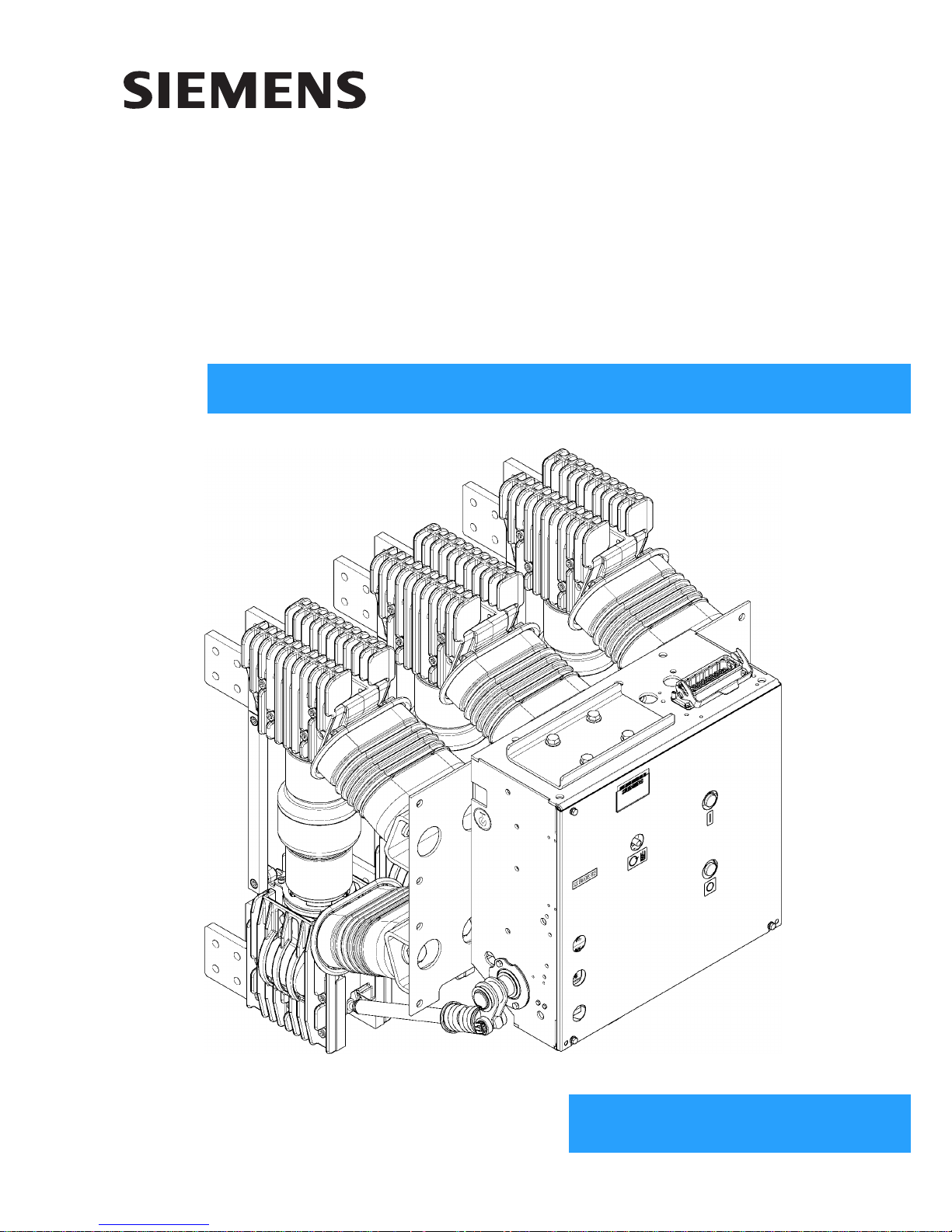
3AH37/38
Vacuum circuit-breaker
12 kV 90 kA as per IEC 62271-100
17.5 kV 50/63/72/80 kA as per IEEE C37.013
24 kV 50/63/72 kA as per IEEE C37.013
OPERATING INSTRUCTIONS
Order no.: 9229 9992 176 0D
Ordering location: IC LMV LP PO P C41
AG 07.2013 en
Page 2

2 9229 9992 176 0D
2013-07-08
For your safety
Signal terms and
definitions
Hazards are classified in accordance with ISO 3864-2 using the following keywords:
• DANGER, WARNING or CAUTION, where there is a risk of personal injury
• NOTE, where there is a risk of material damage.
Hazards are classified and indicated in the operating instructions and on the vacuum
circuit-breaker as follows:
Qualified personnel are, for the purposes of this manual or the warning notices on the vacuum circuit-
breaker, persons who are familiar with the transport, storage, placement, assembly,
commissioning, operation and maintenance of the product and have the
qualifications corresponding to their activity, i. e:
• training and authorization to energize, de-energize, clear, ground and tag
circuits and equipment in accordance with established safety practices.
• training in the proper care and use of protective equipment in accordance with
established safety practices;
• training in providing first aid.
Product liability
DANGER
signal word used to indicate an imminently hazardous situation which,
if not avoided, will result in death or serious injury.
WARNING
signal word used to indicate a potentially hazardous situation which,
if not avoided, could result in death or serious injury.
CAUTION
signal word used to indicate a potentially hazardous situation which,
if not avoided, could result in minor or moderate injury.
Note
indicates a potentially damaging situation.
If the damaging situation is not avoided, the product or something in its vicinity
may sustain damage.
Note
Product liability claims are upheld only if the replacement of the purchased spare
parts is performed by personnel that has been trained and certified by Siemens.
Page 3

9229 9992 176 0D 3
2013-07-08
Table of contents
For your safety ................................................................................................................................................... 2
Transport, storage and packing .................................................................................................................. 5
Transport ............................................................................................................................................................. 5
Unpacking (I) ....................................................................................................................................................... 6
Unpacking (II) .................................................................................................................................................... 11
Unpacking (III) ................................................................................................................................................... 13
Reusing the transport unit ................................................................................................................................. 16
Storage ............................................................................................................................................................. 16
General information ....................................................................................................................................... 17
Range of application ......................................................................................................................................... 17
Standards .......................................................................................................................................................... 18
Design approval as per X-Ray Ordinance ........................................................................................................ 18
Scope of delivery .............................................................................................................................................. 18
Description ........................................................................................................................................................ 19
Design ............................................................................................................................................................... 19
Interlocking devices .......................................................................................................................................... 32
Rating plate ....................................................................................................................................................... 34
Technical data ................................................................................................................................................... 34
Ambient conditions ............................................................................................................................................ 36
Installation altitudes .......................................................................................................................................... 36
Switching times ................................................................................................................................................. 37
Circuit diagrams ................................................................................................................................................ 38
Installation ......................................................................................................................................................... 43
Attachment in the switching cubicle .................................................................................................................. 43
Earthing ............................................................................................................................................................. 46
Electrical connection of the prime conductor .................................................................................................... 47
Operation ............................................................................................................................................................ 51
Commissioning ................................................................................................................................................. 51
First closing operation ....................................................................................................................................... 52
Closing .............................................................................................................................................................. 53
Opening ............................................................................................................................................................ 53
Maintenance ...................................................................................................................................................... 55
Maintenance and servicing ............................................................................................................................... 55
Interrupter service life ....................................................................................................................................... 58
Accessories and spare parts ............................................................................................................................. 58
Manufacturer's product liability .......................................................................................................................... 59
Disposal ............................................................................................................................................................ 59
Service .............................................................................................................................................................. 59
Index of keywords .......................................................................................................................................... 61
Legend for all pages ...................................................................................................................................... 63
Note
Sections with Addendum (I), (II) or (III)
Sections with Addendum (I) refer to vacuum circuit-breakers with a rated operating current of < 5000 A. Sections
with Addendum (II) refer to vacuum circuit-breakers packed with brackets with vertical connecting bars and a rated
operating current of ≤ 4000 A. Sections with Addendum (III) refer to vacuum circuit-breakers with a rated operating
current of 5000 A.
If no addendum is given, the information is applicable for all 3AH37/38 vacuum circuit-breakers.
Page 4

4 9229 9992 176 0D
2013-07-08
Blank page
Page 5
Transport, storage and packing
9229 9992 176 0D 5
2013-07-08
Transport, storage and packing
Transport
Transport weight Refer to the delivery slip for the weight of the transport unit.
Place the transport unit on a level, non-slip and pressure-resistant surface for
intermediate storage.
Transport vacuum circuit-breaker in the original transport unit up until the installation
site or storage location.
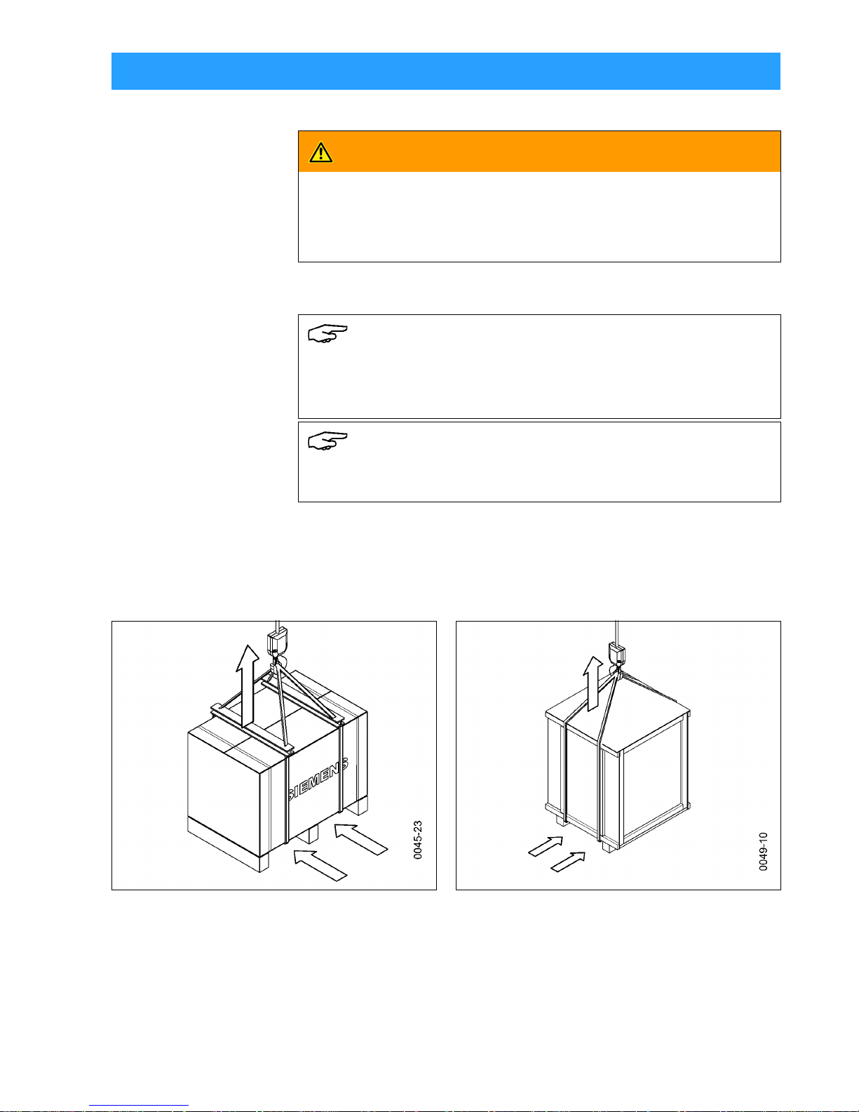
Transporting with crane or fork lift
WARNING
Heavy transport weight
Transport unit may fall and fail and sling gear may break.
Use lifting gear, transporting and sling gear suited to the requirements and loadcarrying capacity. Observe transport symbols.
Note
Observe stacking heightFor transport, not more than three constructionally
identical transport units must be piled on top of each other.
Observe loads specified on the transport unit.
Note
Secure loadFor transport, secure the load in such a way that the transport unit
is not at risk.
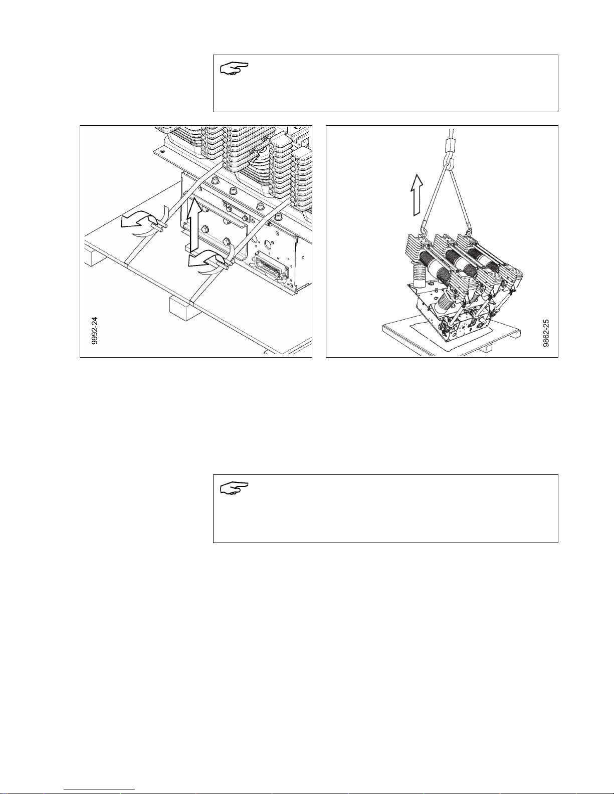
Fig. 1 Transporting the pallet with carton (I) Fig. 2 Transporting the wooden case (III)
Page 6

Transport, storage and packing
6 9229 9992 176 0D
2013-07-08
Transporting with packing Transport the transport unit to the installation site or storage location
• with a fork lift or
• with sling gear suspended from a crane
- at an angle of twist of approx. 60° or
- with a spreader bar.
After receipt of delivery:
Checking
the transport unit
• Check transport unit for damage;
• Major damage must be documented photographically.
• Ensure that any damage to the transport unit is confirmed by the transport
company.
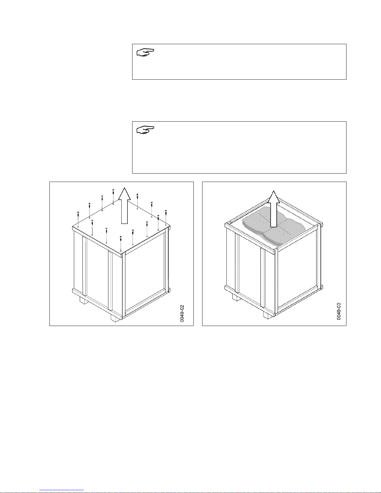
Unpacking (I)
Working equipment Required tools:
- Knife/scissors
- Lifting equipment with lifting gear
- Pliers or lever
Note
Some of the images in this section show a different circuit-breaker type. These
images are exemplary and also apply to the vacuum circuit-breaker 3AH37/38.
CAUTION
Risk of injury from sharp edges!
Fasteners may break, leaving sharp edges.
Always use a suitable tool to lever out fasteners.
Note
Do not cut open or damage the carton, since it is designed to be reused and
because of the belt straps located underneath.
Belt straps could be severed on the pallet floor when cutting open the carton.
The vacuum circuit-breaker is attached to the pallet with belt straps. It is not
permissible to transport the vacuum circuit-breaker on the pallet without using
belt straps (see Fig. 5).
Page 7
Transport, storage and packing
9229 9992 176 0D 7
2013-07-08
Opening the transport unit • Place the transport unit on a level, non-slip and pressure-resistant surface.
• Remove lifting gear or transport means.
• Remove plastic wrap.
• Lever out fasteners from the carton and lift off carton.
Fig. 3 Removing the carton
Note
Do not use the vacuum circuit-breaker if parts are broken, i.e. if you find cracks,
flakings, bent metal parts, damaged plug-in contacts, tears or bare cables.
Send it back in its original transport unit (see “Reusing the transport unit”,
page 16).
Note
Carrying straps may scrape along the vacuum circuit-breaker and damage it.
If necessary, cover carrying straps with edge protection.
Select length and position of the carrying straps so that the pole heads are not
compressed.
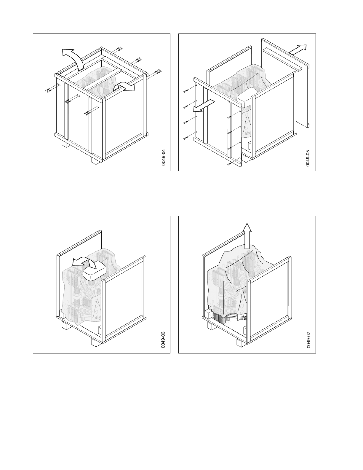
Page 8
Transport, storage and packing
8 9229 9992 176 0D
2013-07-08
• Remove partitions and accessory pack and store safely in the packaging for
later attachment.
• Remove foil from the vacuum circuit-breaker.
• In the case of overseas packaging, push the lower foil onto the pallet floor.
• Check delivery for completeness.
• Check vacuum circuit-breaker for damage.
• If the vacuum circuit-breaker is damaged, ship it back in the transport unit
(see “Reusing the transport unit” on page 16).
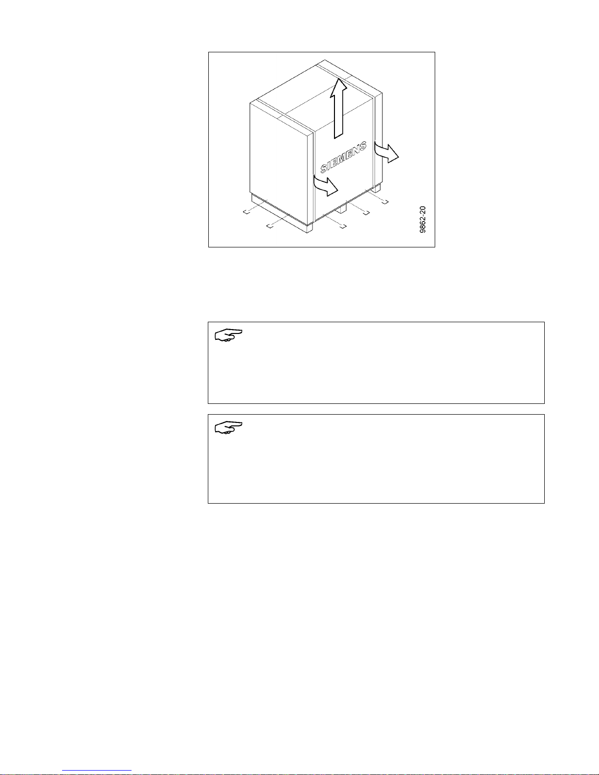
Transporting with pallet,
without carton
The vacuum circuit-breaker can be transported with the pallet, without the carton.
• Thread carrying straps under the pallet or
• Transporting with fork lift.
Fig. 4 Removing partitions and foil Fig. 5 Transporting with pallet possible
Page 9
Transport, storage and packing
9229 9992 176 0D 9
2013-07-08
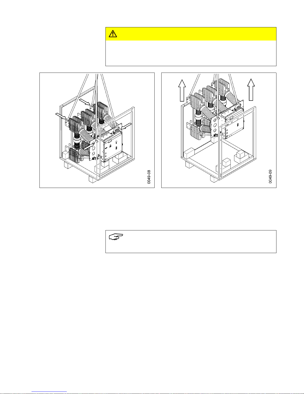
Transporting without pallet • Remove all tensioning belts and bits of fastening wood.
• Remove accessory pack, if applicable.
• Screw suitable eye bolts into the outer pole heads parallel to each other.
• Hang sling gear into the eye bolts.
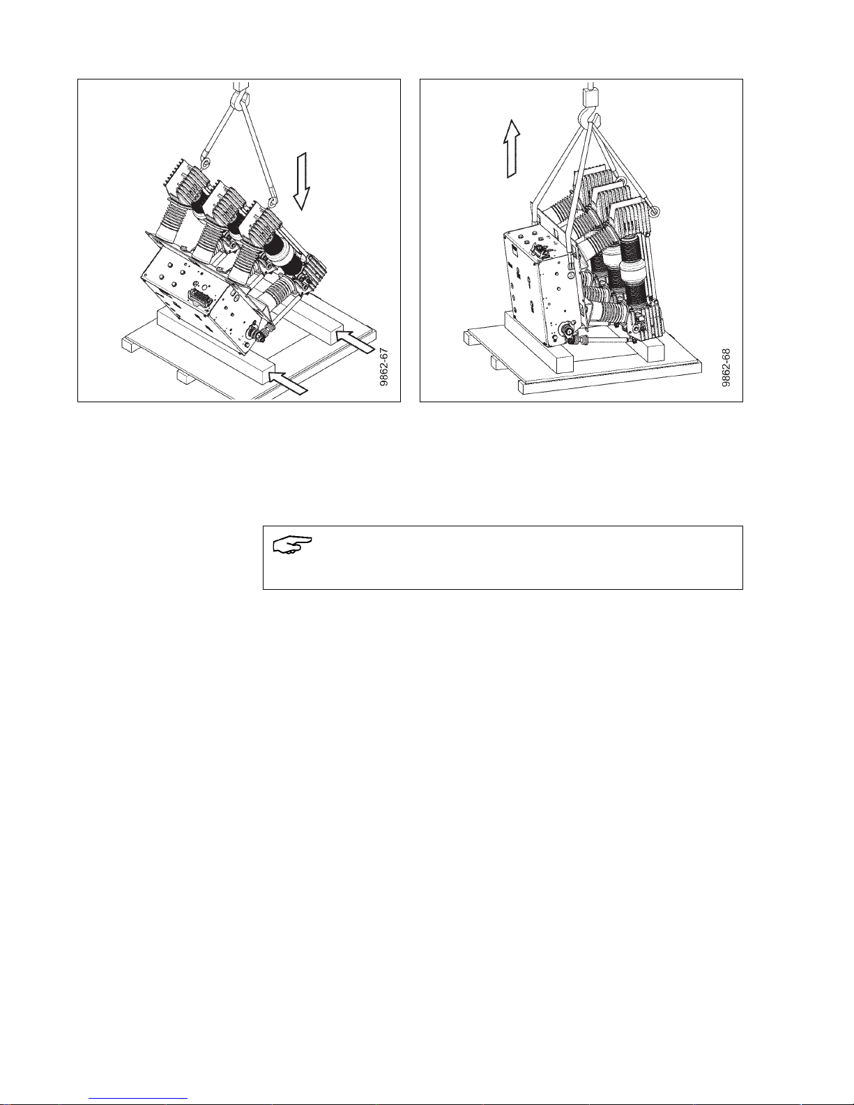
• Carefully lift vacuum circuit-breaker off the pallet just enough that pieces of
square timber can be placed underneath.
Note
When fastening the eyebolts to the pole heads, ensure that the contact surfaces
are not damaged.
Fig. 6 Removing the tensioning belts Fig. 7 Screwing in eye bolts and lifting the vacuum
circuit-breaker
Note
Place pieces of square timber onto the pallet in such a way that the insulating
operating rods, contact pressure springs, angle levers and dashpots are not
damaged when setting down.
Page 10
Transport, storage and packing
10 9229 9992 176 0D
2013-07-08
• Set the vacuum circuit-breaker down onto the square timbers.
• Hang further sling gear into the transport boreholes.
• Transport to installation site or leave suspended from crane for further
work steps.
Fig. 8 Positioning the square timbers and setting
down the vacuum circuit-breaker
Fig. 9 Transporting without pallet
Note
Keep partitions and accessory pack ready for the installation.
Page 11
Transport, storage and packing
9229 9992 176 0D 11
2013-07-08
Unpacking (II)
Variant with bracketsRemove carton as described in Fig. 3.
Working equipment Required tools:
- Knife/scissors
- Screwdriver
- Open-end wrench
- Lifting equipment with lifting gear.
Transporting with brackets • Remove partitions and accessory pack and store safely in the packaging for
later attachment.
• Attach suitable bolt in the middle pole head.
• Attach sling gear to bolt and to transport boreholes.
Fig. 10 Removing partitions and foil Fig. 11 Lifting the vacuum circuit-breaker
Page 12
Transport, storage and packing
12 9229 9992 176 0D
2013-07-08
Transporting without
brackets
• Only lift the vacuum circuit-breaker so that all sling gear is tensioned.
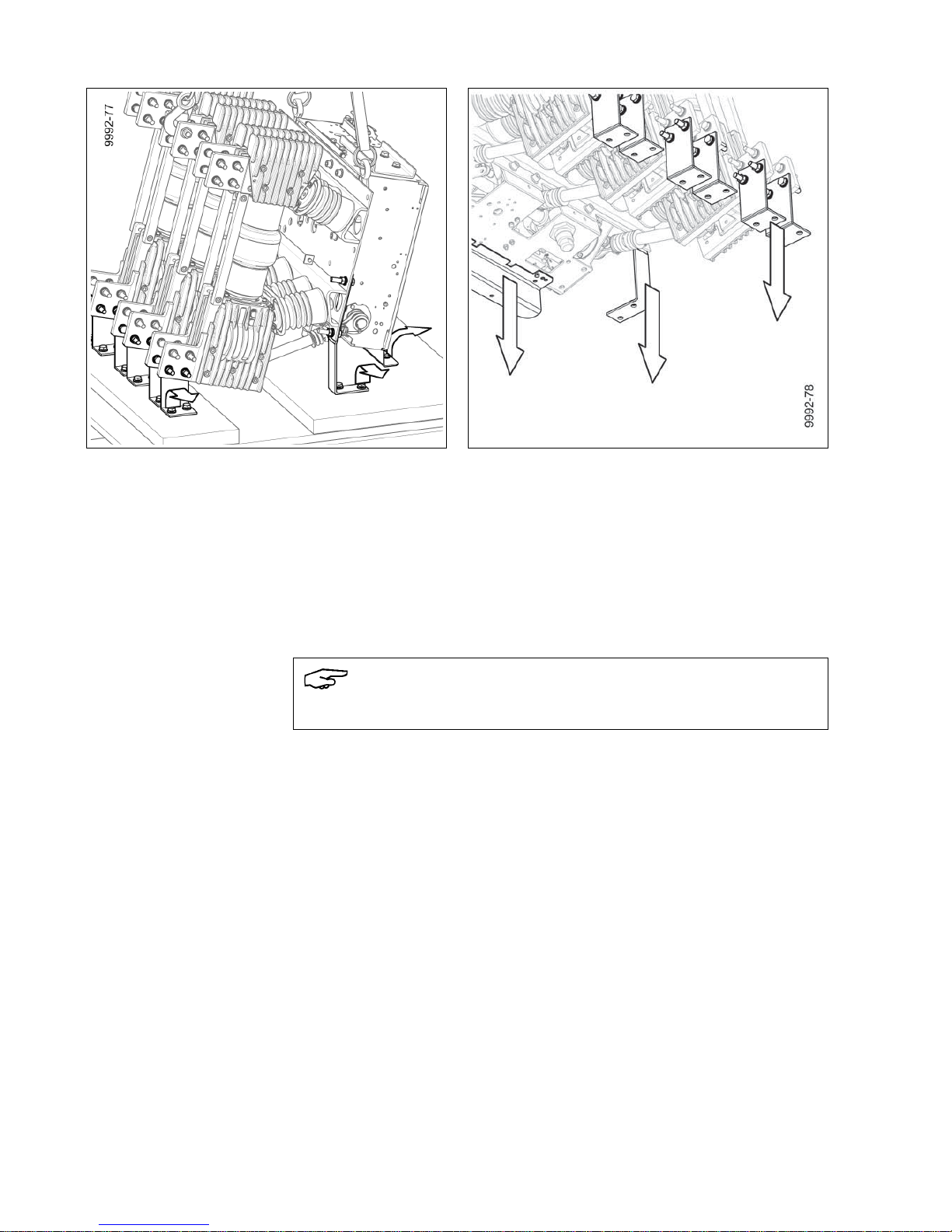
• Remove angle plate and bracket screws from the pallet.
• Lift the vacuum circuit-breaker from the pallet.
• Remove all screw connections from the brackets on the pole plate and the
terminals.
• Remove angle plate below mechanism box.
• Transport to installation site or leave suspended from crane for further
work steps.
Fig. 12 Removing screws from the pallet Fig. 13 Removing the angle plate and brackets
Note
Keep partitions and accessory pack ready for the installation.
Page 13
Transport, storage and packing
9229 9992 176 0D 13
2013-07-08
Unpacking (III)
Working equipment Required tools:
- Screwdriver
- Knife/scissors
- Lifting equipment with lifting gear.
Opening the transport unit • Place the transport unit on a level, non-slip and pressure-resistant surface.
• Remove lifting gear or transport means.
• Unscrew all the screws from the cover and lift it off.
• Take out the partitions and check for damage.
Note
Some of the images in this section show a different circuit-breaker type. These
images are exemplary and also apply to the vacuum circuit-breaker 3AH37/38.
Note
Do not use the vacuum circuit-breaker if parts are broken, i.e. if you find cracks,
flakings, bent metal parts, damaged plug-in contacts, tears or bare cables.
Send it back in its original transport unit (see “Reusing the transport unit”,
page 16).
Fig. 14 Removing the cover Fig. 15 Taking out the partitions
Page 14
Transport, storage and packing
14 9229 9992 176 0D
2013-07-08
• Unscrew all the screws from the side walls.
• Take the supports out of the transport unit.
• Remove the side walls.
• Remove accessory pack and store safely in the packaging for later attachment.
• Remove foil.
• Check the vacuum circuit-breaker 3AH37/38 for damage.
• Undo tensioning belts, if applicable.
Fig. 16 Removing the supports Fig. 17 Removing the side walls
Fig. 18 Taking out the accessory pack Fig. 19 Removing the foil
Page 15
Transport, storage and packing
9229 9992 176 0D 15
2013-07-08
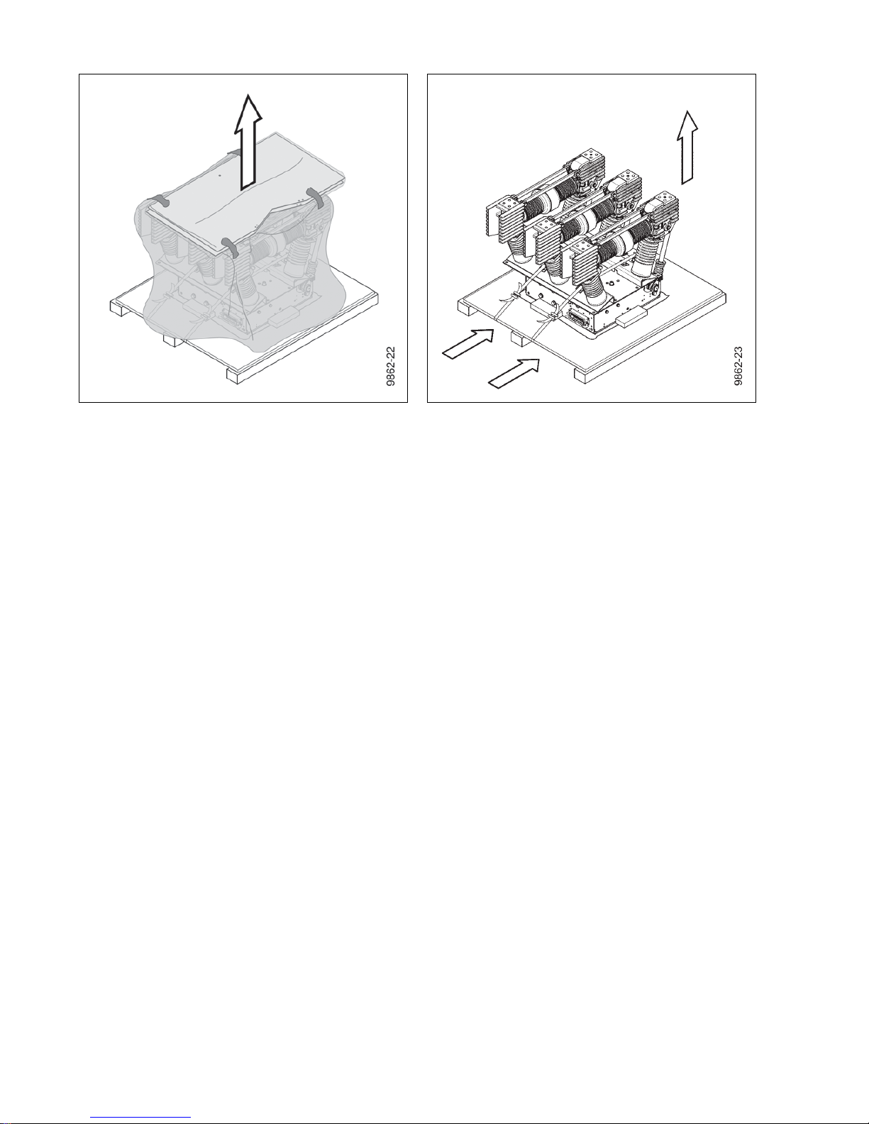
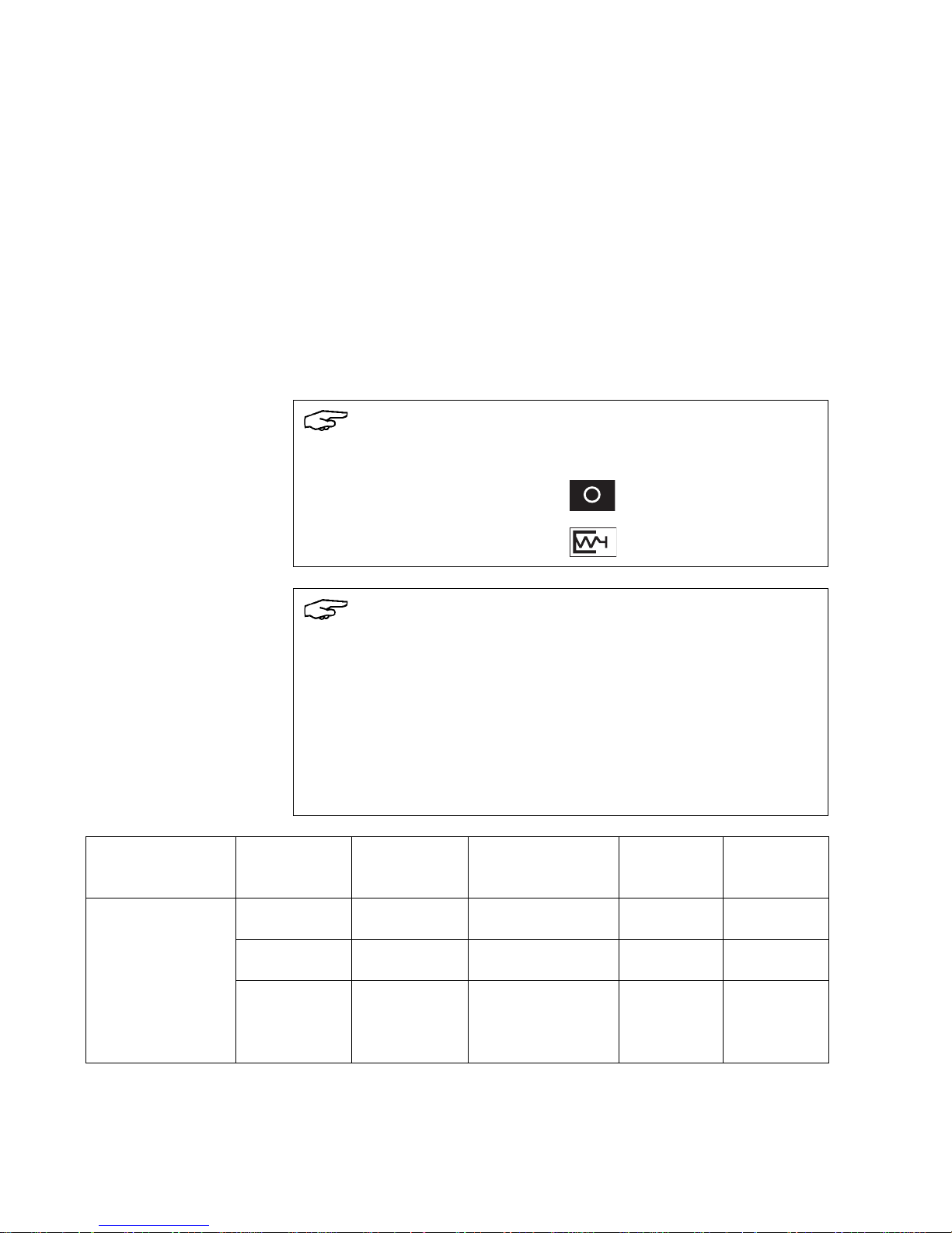
Transporting to the
installation site
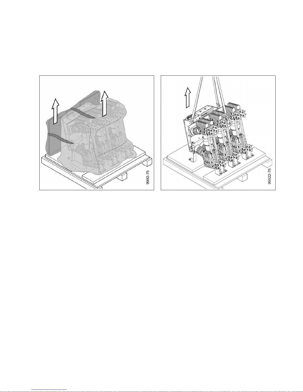
• Hook crane hooks into the transport screws and into the openings on the
mechanism box.
• Observe crane hook symbols.
• Vertically lift out vacuum circuit-breaker.
CAUTION
Crushing hazard
Hands may get crushed when lifting out the vacuum circuit-breaker.
Do not reach between the transport box and the vacuum circuit-breaker.
Fig. 20 Preparing for lifting out Fig. 21 Lifting out
Note
Keep partitions and accessory pack ready for the installation.
Page 16
Transport, storage and packing
16 9229 9992 176 0D
2013-07-08
Reusing the transport unit
Reusing the transport unit To transport the vacuum circuit-breaker again, the pallet with carton or the wooden
case with the most components can be reused.
Do not reuse severed tensioning straps or plastic wrap.
Pack the vacuum circuit-breaker in reverse order:
• Attach the vacuum circuit-breaker safely to the pallet using the appropriate
tools.
• Cover with foil and seal with adhesive tape.
• Attach accessories pack.
• Attach carton securely to the pallet base.
• Screw the wooden case back together.
• Before returning to the factory, ask the responsible Siemens representative for a
returned goods number (see also “Service” on page 59).
• When returning a vacuum circuit-breaker, always indicate the type and serial
number (see “Rating plate” on page 34).
Storage
Note
Store the vacuum circuit-breaker in the following condition:
• OPEN switching position
• Closing spring discharged
Note
Risk of corrosion damage if stored improperly!
If the storage conditions listed below are met, the vacuum circuit-breaker can be
stored for up to a year in its transport unit.
If the storage conditions are not met, the vacuum circuit-breaker cannot be stored
in the transport unit any longer than 6 months.
If storage of longer than one year is planned, unpack the vacuum circuit-breaker
from the transport unit. Further storage may necessitate fresh corrosion
protection, and it must be ensured that the vacuum circuit-breaker cannot be
damaged.
Storage room Transport unit Storage time Temperature range Comments Number of
units per
stack
Enclosed, dry, well
ventilated and as
free from dust as
possible, with a
relative humidity of
less than 60 %.
unopened max. 6 months -40 °C to +55 °C — max. 4
unopened max. 1 year -5 °C to +40 °C — max. 4
open over 1 year -5 °C to +40 °C
if necessary,
with new
corrosion
protection
—
Page 17

General information
9229 9992 176 0D 17
2013-07-08
General information
Smooth and safe operation of this device requires proper transport and storage, and
professional installation and assembly as well as careful operation and
maintenance.
The basic version and all listed configurations of the vacuum circuit-breakers
3AH37/38 are type-tested devices as per IEEE (12 kV 90 kA as per IEC).
Range of application
Vacuum circuit-breakers 3AH37/38 are indoor circuit-breakers for high switching
capacity and a rated voltage range of 17.5 kV and 24 kV (additionally 12 kV 90 kA).
Under normal operating conditions, the vacuum circuit-breakers 3AH37/38 are
maintenance-free up to 10 000 operating cycles.
Intended use 3AH37/38 vacuum circuit-breakers are suitable for switching any type of alternating
current circuits under normal operating conditions, such as:
• Three-phase motors for reversing, turning and direct operation
• Transformers
• Capacitors
• Generators
• Resistor consumers.
Suitable for high frequency of operation and unlimited on-time.
3AH37/38 vacuum circuit-breakers operate in continuous, periodic and short-time
operation.
WARNING
Dangerous voltage and mechanical movements
When operating electrical devices, certain parts will always be live, and
mechanical parts may move very quickly, even when remotely controlled.
If the warnings are not observed, serious injury or damage to material may be
the result.
Only personnel with the relevant qualifications may work on or in the vicinity of
this device. This personnel must be familiar with all the warnings and servicing
measures specified in these operating instructions.
Note
In the event of subsequent attachments or fittings, e. g. locking parts in
connection with switchgear, ensure that
• fast moving parts are not additionally loaded by masses or forces and
• additional parts are sufficiently far away especially from moving and live
parts.
If vacuum circuit-breakers are to be equipped with additional functions by the
customer, we recommend consulting the factory, since tried and tested solutions
are frequently available (see also “Additional equipment” on page 23).
Page 18

General information
18 9229 9992 176 0D
2013-07-08
Standards
The 3AH37/38 vacuum circuit-breakers comply with the regulation IEEE C37.013.
All 3AH37/38 vacuum circuit-breakers comply with the specifications for C2-,
E2- and M2-class circuit-breakers in accordance with IEC 62271-100.
Design approval as per X-Ray Ordinance
The vacuum interrupters installed in the vacuum circuit-breakers are of a design
approved under the X-Ray Ordinance (RöV) of the Federal Republic of Germany.
They meet the requirements of RöV of 8 January 1987 (BGbl. I, page 114) § 8 and
Annex II No. 5 up to the level of the rated voltage stipulated according to
DIN VDE/IEC.
Scope of delivery
Delivery includes:
• Vacuum circuit-breaker 3AH37/38
• Hand crank for circuit-breaker 3AX 1530-2B (optional)
• If applicable, partitions with mounting drawing
• Operating instructions and unpacking instructions
• Circuit-breaker-specific circuit diagrams
Page 19
Description
9229 9992 176 0D 19
2013-07-08
Description
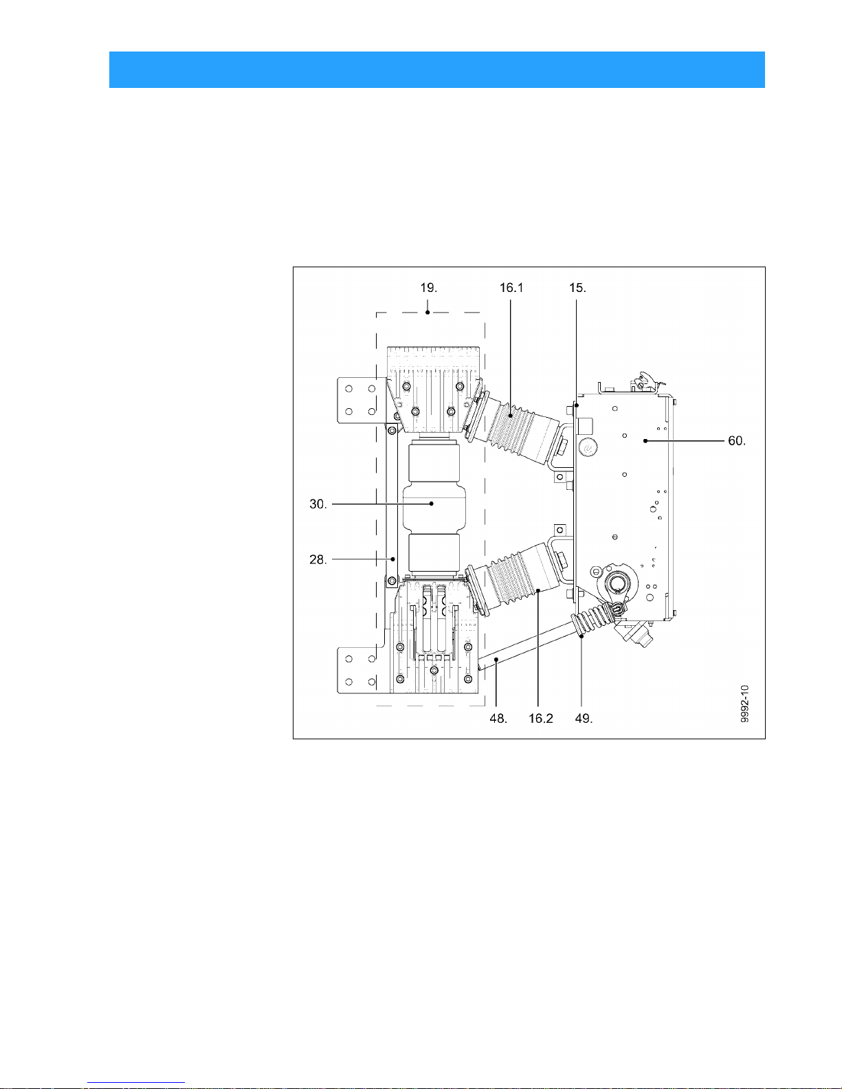
Design
Vacuum circuit-breaker The 3AH37/38 vacuum circuit-breaker consists of
• the mechanism box (60.),
• the 3 pole assemblies (19.) with vacuum interrupters (30.),
• the cast resin post insulators (16.1 and 16.2) with reinforcing struts (28.) and
• the insulating operating rods (48.) with contact pressure springs (49.) required
for contact actuation.
Each of the 3 pole assemblies (19.) is carried by the cast resin post insulators
(16.1 and 16.2) that are screwed to the pole plate (15.).
Fig. 22 Side view
15. Pole plate
16.1 Upper post insulator
16.2 Lower post insulator
19. Pole assembly, complete
28. Strut
30. Vacuum interrupter
48. Insulating operating rods
49. Contact pressure spring
60. Mechanism box
Page 20
Description
20 9229 9992 176 0D
2013-07-08
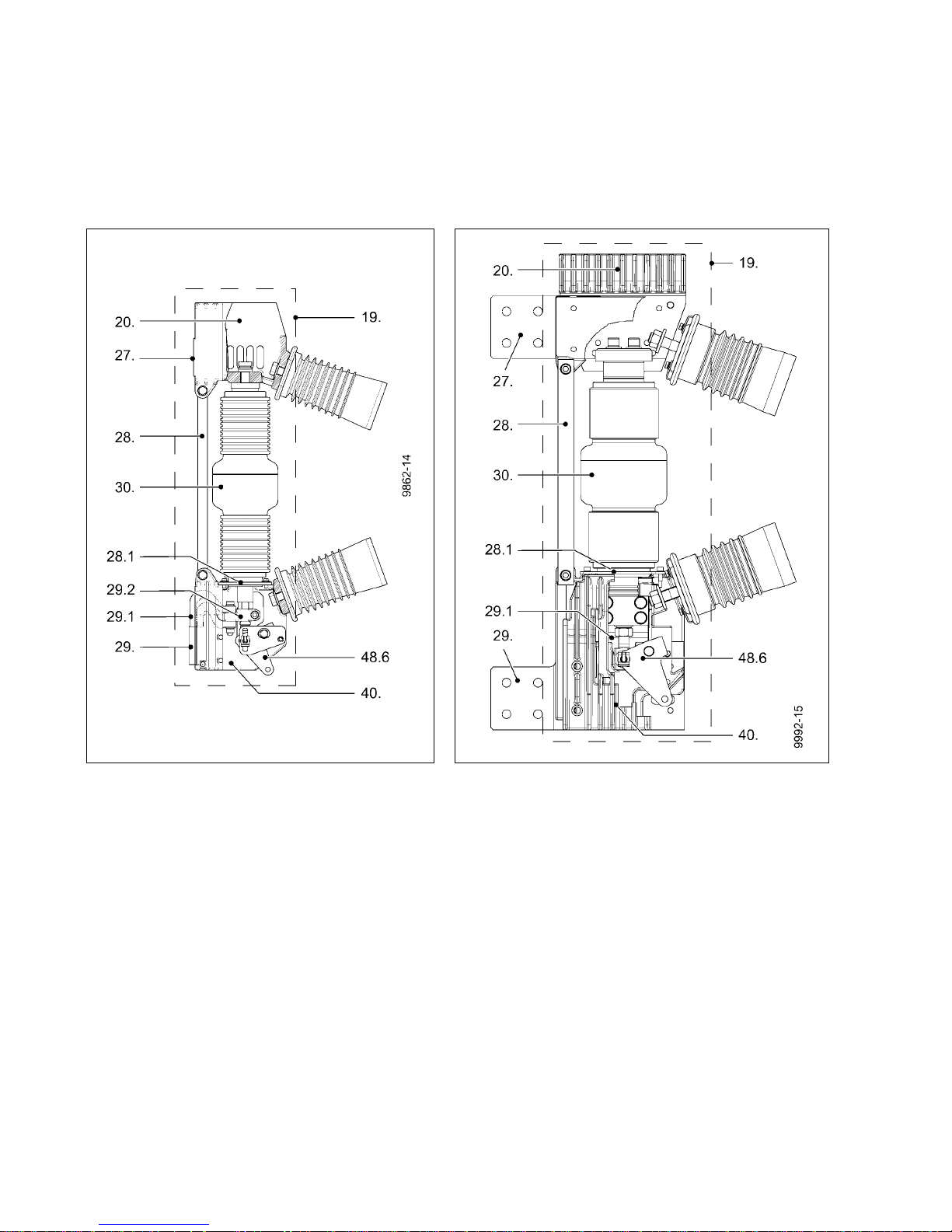
Pole assembly The pole assembly (19.) of the 3AH37/38 vacuum circuit-breaker consists of
• the upper interrupter support (20.)
• with the upper terminal (27.)
• of the vacuum interrupter (30.);
• the lower interrupter support (40.) with the lower terminal (29.) and the
clamp (29.2) with flexible connector (29.1);
• as well as the angle lever (48.6.).
The centering (28.1) and the struts (28.) relieve the interrupters of external forces.
Contact system in the vacuum interrupters
A slight change in the contact stroke that occurs over the entire useful life of the
vacuum circuit-breaker has no effect on its function. There is no need for a status
indicator for the contact system.
Fig. 23 Pole assembly (I) Fig. 24 Pole assembly (II or III)
19. Pole assembly 29.1 Flexible connector
20. Upper interrupter support 29.2 Clamp
27. Upper terminal 30. Vacuum interrupter
28. Strut 40. Lower interrupter support
28.1 Centering 48.6 Angle lever
29. Lower terminal
Page 21

Description
9229 9992 176 0D 21
2013-07-08
Mechanism box The mechanism box (60.) contains all the electrical and mechanical components
required to switch the vacuum circuit-breaker on or off. Insulating operating rods
(48.) transfer the switching movement to the pole assemblies.
The mechanism box is closed with a removable cover (60.1).
There are openings in the cover (60.1) for the operating and indicator elements.
Functions The CLOSE pushbutton (53.) is used to close the vacuum circuit-breaker. The motor
(50.4) immediately charges the closing spring (62.). If the supply voltage for the
motor fails, the closing spring can be charged with a hand crank (50.). There is an
opening (50.1) for this in the cover, behind which you will find the hand crank
coupling (50.5) of the gear unit (50.2).
Indicators The charged state of the springs is indicated via the spring state indicator (55.). The
position indicator (59.) shows the CLOSED or OPEN state. The operating cycle
counter (58.) indicates the number of operating cycles. An operating cycle consists
of one closing and one opening. The rating plate (51.) is attached to the mechanism
box and readable through an opening (51.1) in the cover.
Fig. 25 Operating and indicator elements
50.1 Opening for hand crank 58. Operating cycle counter
51. Ratinng plate 59. Position indicator CLOSED-OPEN
53. CLOSE pushbutton 60.1 Cover
54. OPEN pushbutton a) Tightening torque Md = 10 Nm
55. Spring state indicator
Page 22

Description
22 9229 9992 176 0D
2013-07-08
Fig. 26 Opened mechanism box
50.2 Gear unit 60. Mechanism box
50.4 Motor M1 61. Dashpot
50.4.1 Position switch 62. Closing spring
50.5 Hand crank coupling 63. Circuit-breaker shaft
51. Rating plate 64. Opening spring
53.1 Closing solenoid Y9 66. Closing damper
54.1 Shunt release Y1 68. Auxiliary switch S1
54.2 Shunt release Y2 68.1 Operating rod (for auxiliary switch S1)
54.3 Transformer-operated release Y4 68.7 Low-voltage interface X0
54.4 Undervoltage release Y7 69. Contactor relay K1
54.5 Transformer-operated release (0.1 Ws) Y6 70. Earth terminal
55. Spring state indicator 71. Heater (condensation water protection)
58. Operating cycle counter
59. Position indicator CLOSED-OPEN
Page 23

Description
9229 9992 176 0D 23
2013-07-08
Equipment
Basic equipment The basic equipment of the 3AH37/38 vacuum circuit-breaker contains:
Additional equipment Every 3AH37/38 vacuum circuit-breaker can also be fitted with the following
equipment:
In addition to the serial shunt release (Y1), the vacuum circuit-breaker can be
equipped with a maximum of 2 releases of the type 3AX11.
For the permitted possible combinations of the additional equipment as well as
special designs, refer to catalogue HG11, or contact the responsible Siemens
representative.
Motor (M1)
Contactor relay (electrical anti-pumping device) (K1)
Closing solenoid (Y9)
Shunt release (Y1)
Auxiliary switch (optional) (S1)
•6NO + 6NC
•12NO + 12NC
Position switch for signal "Closing spring charged" (S41, S42)
Circuit-breaker tripping signal, cut-out switch (S6, S7)
Low-voltage interface (optional) (X0)
• Plug-connector with sleeve housing 64-pin
• Plug-connector with sleeve housing 24-pin
• Terminal strip (X1)
Operating cycle counter
Mechanical anti-pumping device
Mechanical manual closing and opening
Shunt release 3AX1101
1)
1) Subsequent installation possible
(Y2, Y3)
Transformer-operated release 3AX1102
1)
(Y4, Y5)
Transformer-operated release 3AX1104 (0.1 AC)
1)
(Y6)
Undervoltage release 3AX1103
1)
(Y7)
Heater (condensation water protection)
1)
Electrical manual closing
2)
Mechanical interlock
1)
Priority opening
2)
2) No subsequent installation possible
Page 24

Description
24 9229 9992 176 0D
2013-07-08
Motor (M1)
*) The operator's supply voltage may deviate from the rated supply voltage of the
vacuum circuit-breaker by -15 % to +10 %.
**) Built-in automatic circuit-breaker with C characteristic
Fig. 28 Recommendation for motor protection device
Contactor relay K1
After the supply voltage is applied and if the closing
spring is discharged, the motor starts immediately and is
automatically deactivated internally after charging has
taken place.
Power consumption, maximum:
• in the event of direct voltage approx. 750 W
• in the event of alternating voltage 1400 W.
In the short charging time, the motor sometimes
operates in the overload range. See Fig. 28 for the rated
current for the required motor short-circuit protection.
Note: The motor protection devices are not included in
the delivery of the vacuum circuit-breaker and must be
ordered separately .
Fig. 27 Motor (50.4)
Rated supply voltage U*)
VDC24DC48DC60DC110
AC 50/60 Hz
110
DC
220
AC 50/60 Hz
230
Recommended rated current of the protective
device I**
)
A16106462 3
If simultaneous CLOSE and OPEN commands are
continuously applied to the vacuum circuit-breaker, it
returns to the open position after being closed.
Via the function of the contactor relay K1, the vacuum
circuit-breaker pauses there until the CLOSE command
is given again.
This prevents continuous closing and opening
(pumping).
Fig. 29 Contactor relay (69.)
Page 25

Description
9229 9992 176 0D 25
2013-07-08
Closing solenoid (Y9) 3AY1510
1 st shunt release (Y1) 3AY1510
The closing solenoid Y9 unlatches the charged closing
spring and switches the vacuum circuit-breaker on
electrically . It is available for DC or AC voltage .
The closing solenoid Y9 is not designed for continuous
operation and is automatically deactivated within the
circuit-breaker.
The operator's supply voltage may deviate from the
rated supply voltage of the vacuum circuit-breaker by
-15 % up to +10 %.
The closing solenoid Y9 can be operated using AC or
DC voltage and is protected against overvoltage.
Power consumption is approximately 140 W / VA
Fig. 30 Closing solenoid (53.1)
In the case of the 1st shunt release Y1, the electrically
fed tripping pulse is passed to the "OPEN" latch by
means of a directly acting magnet armature, thus
switching off the vacuum circuit-breaker.
The 1st shunt release Y1 is not designed for continuous
operation and is automatically deactivated within the
circuit-breaker.
The operator's supply voltage may deviate from the
rated supply voltage of the vacuum circuit-breaker by 30 % to +10 % in the event of DC voltage and by -15 %
to +10 % in the event of AC voltage.
The 1st shunt release Y1 can be operated using AC or
DC voltage and is protected against overvoltage.
Power consumption is approximately 140 W / VA
Fig. 31 1st shunt release (54.1)
Page 26

Description
26 9229 9992 176 0D
2013-07-08
Auxiliary switch S1
Breaking capacity
Fig. 33 Breaking capacity of the auxiliary switch 3SV92
Two versions of the auxiliary switch S1 are available for
delivery: with 6 or 12 NO / NC contacts each.
Rated insulation voltage: 250 V AC/DC
Insulation group: C as per VDE 0110
Continuous current: 10 A
Closing capacity: 50 A
Fig. 32 Auxiliary switch (68.)
AC 40 to 60 Hz DC
Operating voltage Operating current Operating voltage Operating current
U (V) I (A) U (V) I (A)
Ohmic
load
Inductive load
(T = 20 ms)
Up to 230 10
24 10 10
48 10 9
60 9 7
110 5 4
220 2,5 2
Page 27

Description
9229 9992 176 0D 27
2013-07-08
Position switch
Circuit-breaker tripping signal, cut-out switch (S6, S7)
S21, S22 Position switches (switch off the motor after
charging)
S3 Position switch (opens when closing spring
is charged)
S41, S42 Position switches (report charging state)
Fig. 34 Position switch (50.4.1)
The position switch S6 makes contact briefly when the
vacuum circuit-breaker is opened by means of an
electrical release.
This contacting can be used for a signal.
In the event of intentional mechanical opening, the
cut-out switch S7 interrupts the contacting.
Fig. 35 Circuit-breaker tripping signal
Page 28

Description
28 9229 9992 176 0D
2013-07-08
Low-voltage interface X0, 64-pin
For connection of the control line, the standard version of the vacuum circuitbreakers is equipped with a 64-pin low-voltage interface X0 (68.7).
The 64-pin plug (68.7.1) for the external terminal, is suitable for crimp termination of
control lines with a nominal cross-section of 1.5 mm
2
.
Terminal strip (optional) Instead of the 64-pin plug (68.7.1), a terminal strip (68.7.2) can be ordered as
interface to the terminal at the customer's site. Assignment of the terminals is done
according to the circuit diagram supplied.
Fig. 36 Low-voltage interface X0 Fig. 37 Terminal strip (optional)
Page 29

Description
9229 9992 176 0D 29
2013-07-08
A further shunt release, transformer-operated release, undervoltage release or
instantaneous release can be installed as a 2nd release.
2nd shunt release (Y2) 3AX1101
Transformer-operated releases (Y4, Y5) 3AX1102, (Y6) 3AX1104
The second shunt release Y2 is installed whenever more
than one shunt release is needed.
In this version, the electrical "off" command is passed by
means of a magnet armature to the "OPEN" latch by
release of an energy storage mechanism, thus switching
off the vacuum circuit-breaker. This tripping solenoid is
not designed for continuous operation. Any necessary
varistors and rectifiers are integrated in the release.
Power consumption is approximately 60 W / VA
Fig. 38 2. Shunt release (54.2)
The transformer-operated releases Y4, Y5 or Y6 consist
of an energy storage mechanism, an unlatching fixture
and an electromagnetic system. If the tripping current is
exceeded (90 % of the transformer-operated release's
rated current), the stored energy mechanism is
unlatched, thus initiating opening of the vacuum circuitbreaker.
For use of the transformer-operated release, matching
transformers are also needed for matching, in addition to
the main current transformers.
Power consumption for 0.5 A and 1 A ≤ 6 VA at ≤ 90 %
of the transformer-operated release's rated current and
with open armature.
Fig. 39 Transformer-operated releases (54.3)
Page 30

Description
30 9229 9992 176 0D
2013-07-08
Undervoltage release (Y7) 3AX1103
The undervoltage release Y7 has an electromagnet system that has voltage
permanently applied to it when the vacuum circuit-breaker is in the closed state. If
the voltage drops below a certain value, the undervoltage release Y7 is unlatched,
thus initiating opening of the vacuum circuit-breaker via the stored energy
mechanism.
Random tripping of the undervoltage release Y7 is generally performed by an
NC contact in the tripping circuit, but can also be done with the aid of an NO contact
by short-circuiting the solenoid coil. In the case of this latter method, the solenoid
coil's short-circuit current is limited by the built-in resistor.
The undervoltage release Y7 can also be connected to voltage transformers.
The undervoltage release Y7 automatically trips the vacuum circuit-breaker if the
rated supply voltage drops to an inadmissible value. Any necessary varistors and
rectifiers are integrated in the release.
Power consumption ≤ 6.5 W or ≤ 7.5 VA
Note
The undervoltage release Y7 must only be operated with the supplied series
resistor R1.
Note
For switching operations (mechanical or electrical), the undervoltage release
3AX1103… must be connected to control voltage, as otherwise closing is not
possible (see “Removing the transport securing device from the undervoltage
release”, page 47).
Fig. 40 Undervoltage release (54.4) Fig. 41 Typical circuit for connection of the
undervoltage release Y7
A
B
R1 resistor
S1 auxiliary switch
Y7 undervoltage release
Page 31

Description
9229 9992 176 0D 31
2013-07-08
Heater (condensation water protection)
Electrical manual closing/electr. locking device
In the basic version, the vacuum circuit-breaker with on-site connection is closed by
direct mechanical unlatching of the closing spring. Instead of this mechanical
manual closing , "electrical manual closing" is also available.
In this version, the closing circuit of the vacuum circuit-breaker module is electrically
actuated by a sensing device and must also be enabled via a command element
from the control room.
With on-site closing, this permits taking into account system-related interlocking and
allows you to prevent unintentional closing by the control room, for example. This
allows for interlocking the vacuum circuit-breaker module, for example, via the
auxiliary contact of a disconnector.
Vacuum circuit-breakers with electrical manual closing cannot be switched
mechanically.
The heater limits condensation and corrosion of the
vacuum circuit-breaker.
To this end, the heater has to be connected to the supply
voltage (see circuit diagram included with the delivery).
The heater's surface temperature is at the most 180 °C.
Power consumption 50 W, Rated voltage AC 230 V
Fig. 42 Heater (71.)
Page 32

Description
32 9229 9992 176 0D
2013-07-08
Interlocking devices
To lock vacuum circuit-breakers as a function of the switching position, the spring
drive mechanisms of the vacuum circuit-breaker can be equipped with an
interlocking device. This is also the case for vacuum circuit-breakers on switch gear
trucks, in withdrawable sections or with disconnectors.
Conditions The vacuum circuit-breaker must only be switched on in operating or disconnected
position. The operating or disconnected position is the position of the vacuum circuitbreaker on the switchgear truck or withdrawable section in the switchgear. At the
same time, the vacuum circuit-breaker may be moved on the switchgear truck or
withdrawable section only when it is open.
Positions of the vacuum circuit-breaker in the switchgear
Disconnected position The isolating distance between the vacuum circuit-breaker contacts and the
switchgear counter-contacts is attained fully.
Operating position The circuit-breaker is inserted fully into the switchgear and the vacuum circuit-
breaker contacts overlap completely with the switchgear counter-contacts.
Mechanical interlock (optional with spring drive mechanism)
An interrogation and actuation component (b) on the system side scans the
operating position (CLOSED/OPEN) of the vacuum circuit-breaker.
CLOSED position If the vacuum circuit-breaker is closed, actuation of the system's interrogation and
actuation component (b) is prevented. A mechanical system in the switchgear truck
or withdrawable section reliably blocks movements of the circuit-breaker on the
switchgear truck or withdrawable section.
OPEN position If the vacuum circuit-breaker is open, the interrogation and actuation component (b)
on the system side actuates, via the stroke (a), the vacuum circuit-breaker's
mechanical interlock and reliably blocks closing of the vacuum circuit-breaker.
Fig. 43 Mechanical interlock
The installation dimensions (c + d) for the interrogation and actuation component (b)
are in the dimension drawing.
X CLOSED position a Stroke (min. 10 mm, max. 30 mm)
Y OPEN position b Interrogation or actuation component (min. actuation force 70 N)
Z View from below c + d see dimension drawing
Page 33

Description
9229 9992 176 0D 33
2013-07-08
Priority opening
To lock the OPEN position, the drive mechanisms of the vacuum circuit-breaker can
be equipped with "priority opening" . This is also the case for vacuum circuitbreakers on switch gear trucks, in withdrawable sections or with disconnectors.
As long as the OPEN pushbutton is actuated, closing with the CLOSE pushbutton is
mechanically locked.
Page 34

Description
34 9229 9992 176 0D
2013-07-08
Rating plate
Technical data
Vacuum circuit-breakers with one phase per interrupter
Fig. 45 Technical data - connection of one phase per interrupter
Fig. 44 Example - vacuum circuit-breaker rating plate 3AH37/38
a Manufacturer
b Type designation
c Works serial number
d Rated voltage U
r
e Rated frequency f
r
f Rated short-circuit breaking
current I
sc
g Rated power frequency withstand
voltage U
d
h Rated lightning impulse withstand
voltage U
p
i Quality control seal
k Year of manufacture
m Rated operating current I
r
n Rated short-circuit duration t
k
o Mass m
p Rated operating sequence
r Classification to standard
Q
600806
Kontr
Made in Germany
Classification to IEEE C37.013, IEC 62271-100: E2, M2, C2
Rated operating sequence: CO - 30 min - CO
Type 3AH3818-8
No. S 3AH3/90004711
U
r 17.5 kV, 50/60 Hz
U
d/Up 50/110
I
sc 63 kA
kV
Year of manufact. 2006
I
r 4000 A
t
k 3s
m 320 kg
9992-16_en
r
p
o
n
m
k
i
b
a
c
d, e
f
g, h
Rated voltage* U
r
kV 17,5 24
Rated operating current I
r
A 3150, 4000, 5000, 6300
Rated lightning impulse withstand voltage (peak value) U
p
kV 110 125
Rated power frequency withstand voltage (effective value) U
d
kV 50
Rated short-circuit breaking current I
sc
kA 50, 63,72
Distance between pole centres mm 275, 300 300
Rated operating sequence A, B A, B
A O - 3 min - CO - 3 min - CO; operating sequence with and without load
B CO - 30 min - CO; operating sequence in the event of short-circuit current
* In the event of a rated frequency fr of 50/60 Hz
Page 35

Description
9229 9992 176 0D 35
2013-07-08
Per phase one vacuum circuit-breaker
Fig. 46 Technical data - connection of one vacuum circuit-breaker per phase
Dimensions and weights
The dimensions of the vacuum circuit-breaker can be taken from the relevant
dimension drawing. If required, these are available from your Siemens
representative.
The weight is given on the rating plate of the vacuum circuit-breaker (see Fig. 44) or
can be taken from the relevant dimension drawing.
Note
If one vacuum circuit-breaker is ordered per phase, the three vacuum circuitbreakers are synchronised at the factory. If one of the vacuum circuit-breakers is
exchanged, the three vacuum circuit-breakers must be re-synchronised.
Rated voltage* U
r
kV 12** 17,5 24
Rated operating current I
r
A4000
4000, 5000,
6300, 8000,
10000, 12000
4000, 5000,
6300, 8000,
10000, 12000
Rated lightning impulse withstand voltage (peak value) U
p
kV 75 110 125
Rated power frequency withstand voltage (effective value) U
d
kV 28 50 50
Rated short-circuit breaking current I
sc
kA 90 50, 63, 72, 80 50, 63, 72
Distance between pole centres mm ** 275 300
Rated operating sequence A, B A, B A, B
A O - 3 min - CO - 3 min - CO; operating sequence with and without load
B CO - 30 min - CO; operating sequence in the event of short-circuit current
* In the event of a rated frequency fr of 50/60 Hz
** Vacuum circuit-breaker with one pole assembly
**
Page 36

Description
36 9229 9992 176 0D
2013-07-08
Ambient conditions
Installation altitudes
Insulating capacity The insulating capacity of insulation in air decreases with rising altitude due to the
lower air density. In conformity with IEC 62271-102, the rated lightning impulse
withstand voltage values given in Fig. 45 are valid up to an installation altitude of
1,000 m above sea level.
As from an altitude of 1,000 m, the insulation level must be corrected as shown in
Fig. 48:
3AH37/38vacuum circuit-breakers are suitable for use in
the following climate classes in accordance with
IEC 60721, Part 3-3:
Class
• Climatic ambient conditions:
3K4
1)
,
3K6
2)
,
3Z2,
3Z5
• Biological ambient conditions: 3B1
• Mechanical ambient conditions: 3M2
• Chemically active substances:
3C2
3)
• Mechanically active substances:
3S2
4)
1) Peak value of the 24-hour means: +35 °C
2) Without ice formation and wind-driven precipitation
3) Without occurrence of salt fog and simultaneous condensation
4) Restriction: clean insulating parts
5) Average value, measured over 24 hours
6) Average value, measured over 1 month
Fig. 47 Ambient conditions
U U0 K
a
U Rated withstand voltage U under standard reference
atmosphere
U
0
Required rated withstand voltage for the installation
location
K
a
Altitude correction factor
K
a
= em
(H - 1000)/8150
Calculating the altitude correction factor Ka:
H = Installation altitude in metres
m = 1 for AC voltage, lightning impulse withstand
voltage (between phases, phase-to-earth, applied
longitudinally)
Example
For a required rated withstand voltage of 75 kV at an
altitude of 2,500 m, an insulation level of at least 90 kV
under standard reference atmosphere conditions is
required:
90 kV 75 kV e
1
(2500 - 1000)/8150
75 kV 1.2
Fig. 48 Altitude correction factor K
a
Page 37

Description
9229 9992 176 0D 37
2013-07-08
Switching times
Fig. 49 Switching times
Closing time = period between starting (command) of the closing movement and
the moment of contact touch in all poles.
Opening time = period between starting (command) of the opening movement and
opening of the last pole.
Arcing time = period from the start of the first arc to extinction of the arcs in all poles.
Break-time = period between starting (command) of the opening movement and
extinction of the arc in the pole extinct last (= opening time + arcing time).
Close/Open time = period in an OPEN/CLOSE cycle between the moment of
contact touch in the first pole during closing and the time when contact touch has
been cancelled in all poles during subsequent opening.
Dead-time = period from the end of the current flow in all poles up to the start of
current flow in the first pole.
Closing time < 75 ms
Opening time
1st shunt release (Y1) < 60 ms
2nd and 3rd release (Y2, Y4, Y6, Y7) < 55 ms
Arcing time < 15 ms
Break time
1st shunt release (Y1) < 75 ms
2nd and 3rd release (Y2, Y4, Y6, Y7) < 70 ms
Dead time 300 ms
Close/Open time
1st shunt release (Y1) < 90 ms
2nd and 3rd release (Y2, Y4, Y6, Y7) < 70 ms
Minimum command duration
Closing solenoid (Y9) 45 ms
1st shunt release (Y1) 40 ms
2nd and 3rd release (Y2, Y4, Y6, Y7) 20 ms
Shortest pulse time for breaker tripping signal
1st shunt release (Y1) > 15 ms
2nd and 3rd release (Y2, Y4, Y6, Y7) > 10 ms
Charging time if actuated electrically (M1) < 15 s
Synchronous operation error between the poles ≤ 2 ms
Page 38

Description
38 9229 9992 176 0D
2013-07-08
Circuit diagrams
The circuit diagrams show all the available components with their wiring options.
Fig. 50 to Fig. 56 show some non-binding examples of vacuum circuit-breakers.
The circuit diagrams for the vacuum circuit-breaker are compiled depending on
your order.
Mechanical manual closing and electrical closing
Fig. 50 Example - circuit diagram connection via low-voltage interface, 64-pin,
basic version
Electrical manual closing and electrical closing
Fig. 51 Example - circuit diagram with connection via low-voltage interface 64-
pin.
This legend is also valid for the following circuit diagrams.
-Y1 -Y2 -Y4
-Y4 -Y5
-Y6 -Y7
-Y7
"OPEN" release
-Y1 -Y2 -Y4
-Y4 -Y5
-Y6 -Y7
-Y7
"OPEN" release
extended auxiliary switch
HA Manual opening S3 Position switch (opens when closing spring is charged)
HE Manual closing S41, S42 Position switches (signal charging status)
K1 Contactor relay (anti-pumping device) S6, S7 Position switches (for breaker tripping signal)
M1 Motor X0 Low-voltage interface
P Energy storage mechanism Y1 1st shunt release
R1 Resistor Y2 2nd shunt release
S1 Auxiliary switch Y4, Y5, Y6 Transformer-operated release
S10, S11 Position switch (mechanical anti-pumping device) Y7 Undervoltage release
S12 Position switch (prevents electrical closing in the event
of mechanical interlocking)
Y9 Closing solenoid
S21, S22 Position switches (switch off the motor after charging) V6 Integrated rectifiers for motor
Page 39

Description
9229 9992 176 0D 39
2013-07-08
1) Integrated varistor
2) Integrated rectifier for AC/DC≥ 100 V
3) Line H07V-K1x2.5sw (as per EN 50525-2-31) when motors are used with DC 24 V / 48 V and 60 V
4) Only if a mechanical closing lock is ordered at the same time
a) Motor winding for DC
b) Motor winding with rectifier for AC
c) Closing
d) Closing with anti-pumping device
Fig. 52 Sample circuit diagram 64-pole (part 1) of the vacuum circuit-breaker
a) b) c) d)
Page 40

Description
40 9229 9992 176 0D
2013-07-08
1) Integrated varistor
2) Integrated rectifier for AC/DC≥ 100 V
a) 1st shunt release with 64-pole plug-connector
b) 1st shunt release with 24-pole plug-connector
c) 2nd shunt release with 64-pole plug-connector
d) 2nd shunt release with 24-pole plug-connector
Fig. 53 Sample circuit diagram (part 2) of the vacuum circuit-breaker
a) b) c) d)
Page 41

Description
9229 9992 176 0D 41
2013-07-08
1) Integrated varistor
2) Integrated rectifier for AC/DC≥ 100 V
3) Attention: connect L+ for direct current (DC)
a) Undervoltage release
b) Low-energy trip-coil
c) 1st transformer-operated release
d) Signal: spring state with 64-pole plug-connector
e) Signal: spring state with 24-pole plug-connector
f) Breaker tripping signal for 64-pole plug-connector
Fig. 54 Sample circuit diagram (part 3) of the vacuum circuit-breaker
a) b) c) d) e) f)
Page 42

Description
42 9229 9992 176 0D
2013-07-08
The unassigned auxiliary switch terminals are wired up (as shown) with the 64-pole
plug bottom.
Fig. 55 Example – auxiliary switch terminals
Fig. 56 Sample switching operation for connection of the undervoltage release Y7
Normal auxiliary switch Extended auxiliary switch
No wiring required if
a) 2nd shunt release Y2 available
b) Undervoltage release Y7 available
a) b)
System wiring Tripping via NO contactTripping via
NC contact
System wiring
Circuit-breaker wiring
Page 43

Installation
9229 9992 176 0D 43
2013-07-08
Installation
Attachment in the switching cubicle
The vacuum circuit-breaker is delivered in OPEN position. Before installing the
vacuum circuit-breaker, remove the transport aids (see “Unpacking (I)” on page 6,
“Unpacking (II)” on page 11 or “Unpacking (III)” on page 13).
Check data Before installing the vacuum circuit-breaker in a switching cubicle, check the details
on the rating plate (see “Rating plate” on page 34) in order to avoid confusion.
DANGER
High-voltage - danger to life
Touching live parts causes an electric shock.
• Do not touch live parts!
• When performing work on the switchgear, deenergise it and earth it.
• The work described in the following sections must only be performed when
the switchgear has been deenergised:
- Take safety measures to prevent reclosing.
- Observe industrial safety regulations.
- Ensure that the vacuum circuit-breaker is installed and commissioned only
by qualified personnel who are familiar with the operating instructions and
observe the warning notices.
WARNING
Risk of injury due to wrong transport means
Using wrong transport means may cause the vacuum circuit-breaker to fall and
injure persons.
• Observe weight
• Use means of transport suited to the requirements and load-carrying
capacity.
• The vacuum circuit-breaker must not fall over.
• Sharp edges may cause injury.
Note
For preliminary work, the vacuum circuit-breaker must be
• secured against falling over,
• placed onto a suitable support or
• suspended from a crane to prepare for installation.
Page 44

Installation
44 9229 9992 176 0D
2013-07-08
Mounting position The 3AH37/38 vacuum circuit-breaker can be installed indoors and vertically or
horizontally (optionally, mechanism box at the bottom) in relation to the interrupters.
Mounting the partitions Carefully take the partitions out of the packaging (see Fig. 4) and mount according
to the supplied mounting drawing.
Mounting the vacuum circuit-breaker
There are a total of 14 fixing holes on the pole plate (15) and on the mechanism
box (60.) for the various types of installation.
Use M12 screws – strength class 8.8 – for fastening. The binding dimension
drawings are relevant.
The framework must be made to suit the operating conditions and have sufficient
load bearing capacity and stability.
Fig. 57 Mounting position
Fig. 58 Example of mounted partitions
Page 45

Installation
9229 9992 176 0D 45
2013-07-08
* bores for M12 screws
Fig. 59 Fastening options Fig. 60 View Y and Z
Page 46

Installation
46 9229 9992 176 0D
2013-07-08
Earthing
Connecting to earth Connect the vacuum circuit-breaker on the earth terminal (70.) to the high-voltage
protective earth as specified (DIN EN 50341).
• Fully unscrew hexagon socket head screw M12 with washer on the earth
terminal (70.).
• Tighten ring terminal for the earth wire with the M12 hexagon screw and washer
on the earth terminal (70.) with 40 Nm.
Connect low-voltage Connect the low-voltage connecting cables in the customer's switch cabinet in such
a way that safe operation as per supplied circuit diagram is guaranteed.
Note
If the 3AH37/38 vacuum circuit-breaker is installed into an earthed metal frame
and is connected permanently and electrically conductive, no separate earthing
needs to be done.
Place serrated washers under the screw heads when fastening the vacuum
circuit-breaker in this case.
Fig. 61 Earth terminal Fig. 62 Connecting earth wire
Page 47

Installation
9229 9992 176 0D 47
2013-07-08
Removing the transport securing device from the undervoltage release
Undervoltage release (Y7)
present?
The vacuum circuit-breaker with an undervoltage release (Y7) 3AX1103 is supplied
with a transport securing device.
• Remove the two top screws (60.2) from the cover (60.1).
• Undo the two bottom screws (60.2) on the cover (60.1) until the cover (60.1) can
be taken off.
• Slightly tilt the cover (60.1) of the mechanism box and lift off.
• Shift the locking screw of the striker from position A to B (see reference note in
mechanism box [60.] of the vacuum circuit-breaker).
• Replace the cover (60.1) in the reverse order
• and fasten the screws (60.2) with a tightening torque of 10 Nm.
Electrical connection of the prime conductor
The busbars can be purchased from the Siemens Service Center.
Busbar connection
Adjust the busbars in such a way that, before fastening, they lie flat easily and fit the
holes on the contact areas of the vacuum circuit-breaker.
Fig. 63 Removing the cover Fig. 64 Removing the transport securing device
A
B
DANGER
High-voltage - danger to life
Test the vacuum circuit-breaker in the switchbay with high-voltage applied only
after faultless functioning has been ascertained (see “Commissioning” on
page 51).
Note
Grease the busbars with contact grease prior to mounting.
Page 48

Installation
48 9229 9992 176 0D
2013-07-08
Preparing contact areas Use a steel brush to carefully brush the contact areas (cross-wise) of the busbars
until they are metallically bright and wipe off any residue using a clean cloth.
After cleaning, very lightly grease the bright contact areas with acid-free Vaseline
(e. g. Shell-Vaseline 8420) and screw together immediately.
Fig. 65 Cleaning the contact areas Fig. 66 Cleaning the contact areas of the busbars
Note
Clean silver spray-plated and copper spray-plated contact areas with a cloth, do
not brush.
Different connection materials (AI/CU) must not be cleaned with the same
cleaning tools.
Silver-plated parts must not be bolted to aluminium bars/rails.
Page 49

Installation
9229 9992 176 0D 49
2013-07-08
Corresponding to the rated current strength, use M12 screws and nuts - strength
class 8.8 - for connection of the busbars and use the appropriate spring elements
and washers.
When tightening the screws, hold the nuts against tightening torque of 70 Nm with
a suitable screwdriver or socket wrench.
Screw-in depths in the upper and lower terminals
See dimension drawings.
Fig. 67 Installing busbars flat Fig. 68 Installing busbars flat
Note
For vacuum circuit-breakers with connecting bars, it is recommended to use the
stainless steel screws or non-magnetisable screws included in the accessory
pack.
Page 50

Installation
50 9229 9992 176 0D
2013-07-08
Blank page
Page 51

Operation
9229 9992 176 0D 51
2013-07-08
Operation
Commissioning
Before commissioning, check the following points to ensure that the 3AH37/38
vacuum circuit-breaker is functioning faultlessly:
DANGER
High-voltage - danger to life
Touching live parts causes an electric shock.
• Do not touch live parts!
• Ensure that the vacuum circuit-breaker is operated only by qualified
personnel who are familiar with the operating instructions and observe the
warning notices.
• Check through all of the items on the checklist and ensure correct functioning
before commissioning.
Checklist
Notes
Does the information on the rating plate (see page 34) match the ordering
data?
Ensure correct operating voltage.
If necessary, clean the vacuum circuit-breaker (details on this in section
“Cleaning” on page 55).
Check that screw connections are tightened securely.
Check terminal strip plug-connection for tightness.
Check functioning of the auxiliary switches.
If necessary, check and adjust customer's devices.
If there is an undervoltage release (Y7) 3AX1103 : has the locking screw
of the striker been shifted from position A to B (see “Removing the
transport securing device from the undervoltage release” on page 47)?
Test switching without supply voltage
Charge the closing spring (62.) with the hand crank (50.) (see Fig. 70),
then actuate the CLOSE pushbutton (53.) and, once closing has been
performed, actuate OPEN pushbutton (54.) .
Test switching with supply voltage
For test switching with motor, switch on the supply voltage. The motor
starts up immediately and charges the closing spring (62.). Check
indicator for charge state of the closing spring (mechanically and
electrically).
Electrically check through auxiliary switch S1 (68.) and position switch
(50.4.1) in both end positions – operate the 3AH37/38 vacuum
circuit-breaker to do so.
Check functioning of the closing solenoid Y9 (53.1) and all available shunt
releases by operating them electrically.
Page 52

Operation
52 9229 9992 176 0D
2013-07-08
First closing operation
If all functions have been checked and are ok, switch on high-voltage while
observing all of the safety regulations and operative requirements.
Charging the closing spring
If the supply voltage is applied, the closing spring (62.) is automatically charged by
the motor (50.4).
Hand crank If the supply voltage fails, the closing spring (62.) can be charged with a hand
crank (50.).
1. For this, fit the hand crank (50.) onto the hand crank coupling (50.5) through
the opening (50.1) with the adapter pushed forward (50.6).
69.Turn clockwise until the spring state indicator (55.) changes over:
WARNING
Do not commission the vacuum circuit-breaker if there are malfunctions.
If the malfunctions or the damage cannot be remedied, contact a Siemens
representative or Siemens Service and, if necessary, send back the vacuum
circuit-breaker .
WARNING
Risk of injury if hand cranks other than the original hand crank are used.
When the supply voltage is present, the motor immediately recharges the spring
after a closing operation. If the hand crank does not have a slip coupling, the hand
crank will also rotate.
To avoid injuries caused by the motor starting suddenly, the vacuum circuitbreaker must be charged only using the original hand crank.
Discharged Charged
Fig. 70 Charging the closing spring with the hand
crank
Fig. 71 Operating elements and spring state indicator
Page 53

Operation
9229 9992 176 0D 53
2013-07-08
The adapter (50.6) of the hand crank (50.) is designed in such a way that the hand
crank becomes uncoupled when the motor supply voltage returns.
Closing
Provided there is no lock-out due to a mechanical interlock, send the closing
command via the CLOSE pushbutton (53.) or the corresponding command element
until the vacuum circuit-breaker is closed and shows and signals the CLOSED
position.
Change of the position indicator (59.):
After switching on and possibly releasing the CLOSE pushbutton (53.), the closing
spring (62.) is immediately automatically charged by the motor and the symbol for
"Closing spring charged" becomes visible in the spring state indicator (55.).
Change of the spring state indicator (55.):
Opening
The opening spring (64.) is charged during the closing operation.
To open, send the opening command via the OPEN pushbutton (54.) or the
corresponding command element until the vacuum circuit-breaker is open and
shows and signals the OPEN switching position.
Change of the switching position indicator (59.) after electrical opening:
The spring state indicator (55.) does not change.
Discharging the closing spring
To discharge the closing spring,
• the supply voltage must be deactivated
• on the vacuum circuit-breaker, actuate the OPEN, CLOSE and OPEN
pushbuttons manually one after the other.
This ensures that the vacuum circuit-breaker is open and the closing spring is
discharged.
OPEN CLOSED
Charged Discharged Charged
Note
If an undervoltage release 3AX1103… is fitted, it must be connected to control
voltage for switching operations (mechanical or electrical), as otherwise closing
is not possible.
CLOSED OPEN
Page 54

Operation
54 9229 9992 176 0D
2013-07-08
Blank page
Page 55

Maintenance
9229 9992 176 0D 55
2013-07-08
Maintenance
Maintenance and servicing
The vacuum circuit-breaker 3AH37/38 is maintenance-free under normal operating
conditions. The maximum permitted mechanical operating cycle number is 10 000.
We recommend you carry out regular visual inspections all the same.
Cleaning
The insulating parts must be clean if their insulating capacity is to be guaranteed.
Wipe insulating parts and any outer circuit-breaker parts with a damp cloth. As a
cleaning agent, use only warm water with a mild, liquid household detergent added.
Special operating conditions
If the vacuum circuit-breaker 3AH37/38 is operated under unfavourable indoor
conditions that deviate from the normal operating conditions (frequent heavy
condensation, dusty air etc.), we recommend regular cleaning of the outer circuitbreaker parts and renewing the corrosion protection, if applicable.
For this, only the following agents may be used on the individual functional parts of
the circuit breaker:
Lubricant:
DANGER
High-voltage - danger to life
Touching live parts is fatal or causes serious physical injury.
Before beginning maintenance work, note the five safety rules for high-voltage
equipment specified in EN 50110-1, namely:
• Isolate from the power supply*)
• Secure against reclosing
• Verify safe isolation from the power supply
• Earth and short-circuit
• Cover or cordon off neighbouring live parts
*
)
On the vacuum circuit-breaker, actuate the OPEN, CLOSE and OPEN
pushbuttons manually one after the other. This ensures that the vacuum circuitbreaker is open and the closing spring is discharged.
Note
The vacuum circuit-breaker should be taken out of the switch cabinet or
switchgear for servicing.
Note
Joints and bearings that cannot be disassembled must not be washed out with a
detergent prior to work.
Bearings, sliding surfaces: Isoflex Topas L 32
Bearings and bearings of the auxiliary switch S1
that are inaccessible in terms of greasing:
Shell Tellus Oil 32
Page 56

Maintenance
56 9229 9992 176 0D
2013-07-08
Lubricants are available from the responsible Siemens representative:
Fig. 72 Bearings and sliding surfaces of the pole side
Order no.
180 g Klüber-Isoflex Topas L 32 3AX11 33-3H
1 kg Shell Tellus Oil 32 (special oil) 3AX11 33-2D
1 kg Klüber-Isoflex Topas L 32 3AX11 33-3E
Isoflex Topas L 32
t Bolts of the angle lever
u Bolts and eyebolt of the insulating operating rod
v Contact pressure spring, spring plate and spring bearing
w Spring guide and bolts of the angle lever
Page 57

Maintenance
9229 9992 176 0D 57
2013-07-08
Fig. 73 Bearings and sliding surfaces of the operating mechanism
Isoflex Topas L 32 Shell Tellus Oil 32
a Crankpin for sensing device actuation b Bearing for deflection lever
c Curve contour f Auxiliary switch
d Close-latch j Circuit-breaker shaft bearing
e Deflection of auxiliary switch p Opening spring bearing
g Opening spring guide r Spring eyelet on closing spring
h Deflection of auxiliary switch
kOPEN-latch
l Curve for OPEN-latch
m End stop
s Contact area of instantaneous release
Page 58

Maintenance
58 9229 9992 176 0D
2013-07-08
Interrupter service life
If switching operations occur frequently under overload or short circuit, the service
life of the vacuum interrupters may be reached prematurely.
Replace the interrupters after reaching the maximum permitted operating cycle
number of 10 000 mechanical or electrical load setting changes (up to the rated
current).
Short-circuit deactivations were proven as per IEEE C37.013 under various
conditions.
Accessories and spare parts
Replacing spare parts To ensure that the device operates reliably, spare parts must be replaced only by
trained and certified personnel.
Fig. 74 Accessories available for order
Always specify the vacuum circuit-breaker's type and serial no. (see “Rating plate”
on page 34) when ordering spare parts.
CAUTION
Risk of injury!
The vacuum circuit-breaker should be taken out of the switch cabinet or
switchgear for servicing.
Separate vacuum circuit-breakers from the control feed voltage or switch it off
and release low-voltage plug or clip connection.
Accessories/spare part Order no. Comments
Operating instructions 9229 9992 100
Hand crank 3AX1530-2B
Klüber lsoflex Topas L32 lubricant 3AX1133-3H 180 g
3AX1133-3E 1 kg
Shell Tellus lubricant 3AXl 133-2D 1 kg tin
Vaseline (contact grease)
e. g. Atlantic white, Atlantic Mineralölwerk GmbH
Pasty consistency, flame point
210 °C, low acid
Page 59

Maintenance
9229 9992 176 0D 59
2013-07-08
Manufacturer's product liability
The manufacturer's product liability shall be excluded if at least one of the following
criteria applies:
• Original Siemens spare parts are not used.
• Fitters carrying out replacements have not been trained and certified by
Siemens.
• Parts have been incorrectly fitted or adjusted.
• Adjustments are not made in accordance with Siemens specifications.
• After installation and adjustment, no final test is performed with a tester
approved by Siemens including documentation of the test results.
To keep documentation complete, it is important that measurement results are
submitted to the responsible Siemens representative.
Disposal
The materials of the vacuum circuit-breaker should be recycled. Disposal of the
vacuum circuit-breakers with minimum environmental impact is possible on the
basis of existing legal regulations.
Metal The circuit breaker's metal components can be recycled as mixed scrap, although
wide-ranging dismantling into sorted scrap and mixed scrap residues is more
environmentally sustainable.
Electronics Electronic scrap must be disposed of in accordance with applicable regulations.
Materials The vacuum circuit-breaker consists of the following materials:
• Steel (partly phosphatised, galvanised and yellow chromated)
• Copper (partly silver-plated)
• Plastics (epoxy resin, polyamide, polyester, polycarbonate, ABS-PC mixture;
partly glass fibre reinforced)
• Rubber materials
•Ceramics
•Lubricant
Packaging If the packaging is no longer needed, it can be fully recycled.
Hazardous substances When delivered by Siemens, the product does not contain any hazardous substances
within the scope of the hazardous substances regulations applicable to the territory of
the Federal Republic of Germany. For operation outside the Federal Republic of
Germany, the applicable local laws and regulations must be complied with.
Further information Contact your Siemens Service Center if you require further information.
Service
For details of contacts for service work, consult Siemens IC LMV SE Services at
• Telephone: +49 180/5247000
• Fax: +49 180/5242471 or
• on the Internet at the Web address: www.siemens.com/energy-support
• by e-mail: support.energy@siemens.com
• or any local Siemens office.
Page 60

Maintenance
60 9229 9992 176 0D
2013-07-08
Blank page
Page 61

Index of keywords
9229 9992 176 0D 61
2013-07-08
Index of keywords
A
Accessories available for order
............................. 58
Altitude correction factor
....................................... 36
Ambient conditions
................................................ 36
Angle lever
............................................................ 20
Auxiliary switch
..................................................... 22
B
Basic equipment
................................................... 23
Bearings and sliding surfaces
............................... 57
Busbars
................................................................. 49
C
Centering
.............................................................. 20
Circuit-breaker shaft
.............................................. 22
Circuit-breaker tripping signal
............................... 27
Climate classes
..................................................... 36
Closing damper
..................................................... 22
Closing solenoid
............................................ 22, 25
Closing spring
............................................... 22, 31
Contact pressure spring
........................................ 19
Contact stroke
....................................................... 20
Contact system
..................................................... 20
Contactor relay
...................................................... 22
Contactor relay K1
................................................ 24
Cover
.................................................................... 21
Cut-out switch
....................................................... 27
D
Dashpot
................................................................. 22
Disconnected position
........................... 32, 34– 35
Distance between pole centres
..................... 34– 35
E
Earth terminal
................................................ 22, 46
Electrical manual closing
.............................. 23, 31
G
Gear unit
............................................................... 22
H
Hand crank
............................................................ 52
Hand crank coupling
............................................. 22
Heater (condensation water protection)
22– 23, 31
High-voltage protective earth
................................ 46
I
Installation altitudes
.............................................. 36
Insulating capacity
................................................ 36
Insulating operating rods
....................................... 19
Interlocking devices
.............................................. 32
Interrupter support
................................................ 20
Interrupter, service life
.......................................... 58
Interrupter, vacuum check
.................................... 58
L
Low-voltage interface
.................................... 22– 23
M
Mechanical anti-pumping device
........................... 23
Mechanical interlock
..................................... 23, 32
Mechanical manual closing
.......................... 23, 31
Mechanical manual opening
.................................. 23
Mechanism box
............................................ 19, 22
Motor
............................................................ 22, 24
Mounting position
.................................................. 44
O
Opening spring
...................................................... 22
Operating cycle counter
................................ 22– 23
Operating position
................................................. 32
Operating rod
......................................................... 22
P
Pole assembly
.............................................. 19– 20
Pole plate
............................................................... 19
Position indicator CLOSED-OPEN
........................ 22
Position switch
.............................................. 22, 27
Post insulator
......................................................... 19
R
Range of application
.............................................. 17
Rated frequency
.................................................... 34
Rated lightning impulse withstand voltage
... 34– 35
Rated operating current
................................ 34– 35
Rated operating sequence
........................... 34– 35
Rated power frequency withstand voltage
.... 34– 35
Rated short-circuit breaking current
............. 34– 35
Rated short-circuit duration
................................... 34
Rated voltage
............................................... 34– 35
Rating plate
.................................................. 22, 34
S
Shunt release
....................................... 22, 25, 29
Spring state indicator
.................................... 21– 22
Standards
.............................................................. 18
Strut
....................................................................... 19
T
Technical data
....................................................... 34
Terminal strip
......................................................... 28
Transformer-operated release
.............. 22– 23, 29
Transformer-operated release (0.1 Ws)
................ 22
U
Undervoltage release
........................... 22– 23, 30
V
Vacuum interrupter
....................................... 19– 20
Vacuum interrupter, contact system
...................... 20
Page 62

Index of keywords
62 9229 9992 176 0D
2013-07-08
Blank page
Page 63

Legend for all pages
9229 9992 176 0D 63
2013-07-08
Legend for all pages
15. Pole plate
16.1 Upper post insulator
16.2 Lower post insulator
19. Pole assembly, complete
20. Upper interrupter support
27. Upper terminal
28. Strut
28.1 Centering
29. Lower terminal
29.1 Flexible connector
29.2 Clamp
30. Vacuum interrupter
40. Lower interrupter support
48. Insulating operating rods
48.6 Angle lever
49. Contact pressure spring
50. Hand crank
50.1 Opening for hand crank
50.2 Gear unit
50.4 Motor M1
50.4.1 Position switch
50.5 Hand crank coupling
50.6 Hand crank adapter
51. Rating plate
51.1 Opening for rating plate
53. CLOSE pushbutton
53.1 Closing solenoid Y9
54. OPEN pushbutton
54.1 Shunt release Y1
54.2 Shunt release Y2
54.3 Transformer-operated release Y4
54.4 Undervoltage release Y7
54.5 Transformer-operated release (0.1 Ws) Y6
55. Spring state indicator
55.1 Opening for spring state indicator
58. Operating cycle counter
58.1 Opening for operating cycle counter
59. Contact position indicator CLOSED-OPEN
59.1 Opening for position indicator CLOSED-OPEN
60. Mechanism box
60.1 Cover
61. Dashpot
62. Closing spring
63. Circuit-breaker shaft
64. Opening spring
66. Closing damper
68. Auxiliary switch S1 (6NO+6NC)
68.0.1 Extended auxiliary switch S1 (12NO + 12NC)
68.1 Operating rod (for auxiliary switch S1)
68.7. Low-voltage interface X0
68.7.1 Plug
68.7.2 Terminal strip
69. Contactor relay K1
70. Earth terminal
71. Heater (condensation water protection)
72. Spring charge release
72.1 Lever of the spring charge release
90. Mechanical interlock
Page 64

Published by
Siemens AG
Infrastructure & Cities Sector
Low and Medium Voltage Division
Medium Voltage & Systems
Schaltwerk Berlin
Nonnendammallee 104
13629 Berlin
 Loading...