

Page 1
www.usa.siemens.com/sdv7
Instruction manual
Type 3AH35-MA vacuum circuit breaker
magnetic-actuator operator module
Installation operation maintenance E50001-F710-K378-X-4A00
Answers for infrastructure.
Page 2
Hazardous voltages and stored energy.
Will cause death, serious injury or property damage.
Even if the circuit breaker and control circuits have been de-energized
for a long time, the power supply capacitors will maintain significant
stored energy. Always discharge the capacitors before maintenance.
Always de-energize and ground the equipment before maintenance.
Read and understand this instruction manual before using equipment.
Maintenance should be performed only by qualified personnel. The use
of unauthorized parts in the repair of the equipment or tampering by
unqualified personnel will result in dangerous conditions which will
cause death, severe injury or equipment damage. Follow all safety
instructions contained herein..
Stored energy and high speed moving parts.
Will result in serious injury. Fingers can be crushed by the magnetic
actuator.
Do not remove guard panel. Do not operate circuit breaker if guard
panel removed.
Important
The information contained herein is general in nature and not
intended for specific application purposes. It does not relieve the
user of responsibility to use sound practices in application,
installation, operation and maintenance of the equipment
purchased. Siemens reserves the right to make changes in the
specifications shown herein or to make improvements at any
time without notice or obligation. Should a conflict arise
between the general information contained in this publication
and the contents of drawings or supplementary material or
both, the latter shall take precedence.
Qualified person
For the purpose of this manual a qualified person is one who is
familiar with the installation, construction or operation of the
equipment and the hazards involved. In addition, this person has
the following qualifications:
Is trained and authorized to
de-energize, clear, ground and tag circuits and equipment in
accordance with established safety procedures.
Is trained in the proper care and use of protective
equipment, such as: rubber gloves, hard hat, safety glasses or
face shields, flash clothing, etc., in accordance with
established safety practices.
Further, a qualified person shall also be familiar with the proper use
of special precautionary techniques, personal protective equipment,
insulation and shielding materials, and insulated tools and test
equipment. Such persons are permitted to work within limited
approach of exposed live parts operative at 50 volts or more, and
shall, at a minimum, be additionally trained in all of the following:
The skills and techniques necessary to distinguish exposed
energized parts from other parts of electric equipment
The skills and techniques necessary to determine the nominal
voltage of exposed live parts
The approach distances specified in NFPA 70E and the
corresponding voltages to which the qualified person will be
exposed
The decision-making process necessary to determine the degree
and extent of the hazard and the personal protective equipment
and job planning necessary to perform the task safely.
Is trained in rendering first aid.
Page 3

Note:
These instructions do not purport to cover all
details or variations in equipment, nor to
provide for every possible contingency to be
met in connection with installation, operation
or maintenance. Should further information be
desired or should particular problems arise
that are not covered sufficiently for the
purchaser’s purposes, the matter should be
referred to the local sales office.
Table of contents
Introduction 04 – 05
Installation checks and functional tests 06 – 09
Vacuum interrupter/operator 10 – 25
Maintenance 26 – 40
Overhaul 41 – 47
The contents of this instruction manual shall
not become part of or modify any prior or
existing agreement, commitment or
relationship. The sales contract contains the
entire obligation of Siemens Industry, Inc. The
warranty contained in the contract between
the parties is the sole warranty of Siemens
Industry, Inc. Any statements contained herein
do not create new warranties or modify the
existing warranty.
Technical data and troubleshooting 48 – 51
Page 4
Introduction
Hazardous voltages and stored energy.
Will cause death, serious injury or property damage.
Even if the circuit breaker and control circuits have been de-energized
for a long time, the power supply capacitors will maintain significant
stored energy. Always discharge the capacitors before maintenance.
Always de-energize and ground the equipment before maintenance.
Read and understand this instruction manual before using equipment.
Maintenance should be performed only by qualified personnel. The use
of unauthorized parts in the repair of the equipment or tampering by
unqualified personnel will result in dangerous conditions which will
cause death, severe injury or equipment damage. Follow all safety
instructions contained herein..
Stored energy and high speed moving parts.
Will result in serious injury. Fingers can be crushed by the magnetic
actuator.
Do not remove guard panel. Do not operate circuit breaker if guard
panel removed.
4
Page 5

Introduction
The type 3AH35-MA vacuum circuit breaker
magnetic actuator module is designed to
meet all applicable ANSI, NEMA and IEEE
standards. Successful application and
operation of this equipment depends as
much upon proper installation and
maintenance by the user as it does upon the
proper design and fabrication by Siemens.
The purpose of this instruction manual is to
assist the user in developing safe and
efficient procedures for the installation,
maintenance and use of the equipment.
Contact the nearest Siemens representative
if any additional information is desired.
Signal words
The signal words “danger,” “warning” and
“caution” used in this manual indicate the
degree of hazard that may be encountered by
the user. These words are defined as:
Danger - Indicates an imminently hazardous
situation that, if not avoided, will result in
death or serious injury.
Warning - Indicates a potentially hazardous
situation that, if not avoided, could result in
death or serious injury.
Caution - Indicates a potentially hazardous
situation that, if not avoided, may result in
minor or moderate injury.
Notice - Indicates a potentially hazardous
situation that, if not avoided, may result in
property damage.
Hazardous procedures
In addition to other procedures described in
this instruction manual as dangerous, user
personnel must adhere to the following:
1. Always work only on a de-energized
circuit breaker. The circuit breaker should
be isolated, grounded and have all control
power removed before performing any
tests, maintenance or repair.
2. Before working on the circuit breaker
make sure the capacitors (106.2) are fully
discharged (refer to Figure 2: Operator
controls and discharging capacitors on
page 7). Verify that the CLOSE/OPEN
indicator (58.0) is in the OPEN position.
Discharge the capacitors (106.2) by
unplugging the connector (105.2) on the
controller board (105.0). The red LED
(106.4) on each of the capacitor boards
(106.1) indicate the state of the charge
on the capacitors (106.2). When the
capacitors (106.2) are discharging, the
LEDs are flashing. This indicates
hazardous voltage. When the LEDs stop
flashing, the capacitors are discharged to
a low voltage.
3. Always let an interlock device or safety
mechanism perform its function without
forcing or defeating the device..
Field service operation and warranty
issues
Siemens can provide competent, well-trained
field service representatives to provide
technical guidance and advisory assistance
for the installation, overhaul, repair and
maintenance of Siemens equipment,
processes and systems. Contact regional
service centers, sales offices or the factory for
details, or telephone Siemens field service at
+1 (800) 347-6659 or +1 (919) 365-2200
outside the U.S.
For medium voltage customer service issues,
contact Siemens at +1 (800) 347-6659 or +1
(919) 365-2200 outside the U.S.
5
Page 6
Installation checks
and functional tests
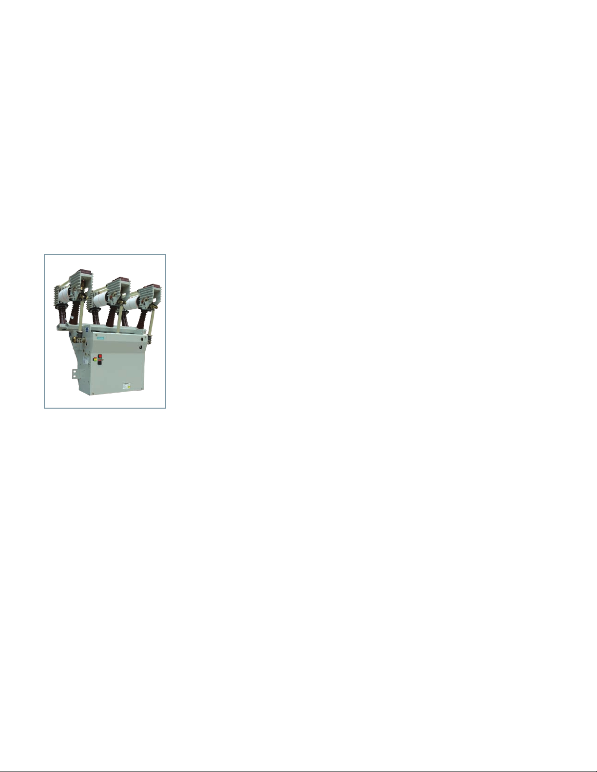
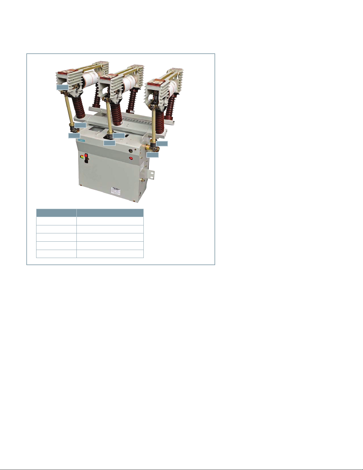
Figure 1: Type 3AH35-MA 27.6 kV
25 kA vacuum circuit breaker
magnetic-actuator operator module
Introduction
This section provides a description of the
inspections, checks and tests to be performed
on the circuit breaker magnetic actuator
module only.
The inspections and checks in this section are
to be performed with the circuit breaker
disconnected and isolated from primary
(high-voltage) power sources.
Inspections, checks and tests
without control power
De-energizing control power
To de-energize control power in the outdoor
circuit breaker, open the control power
disconnect device in the relay and control
compartment.
The control power disconnect device is
normally a fused knife switch. Opening the
knife switch de-energizes control power to
the circuit breaker operating mechanism. In
some outdoor circuit breakers, a molded-case
circuit breaker or pullout-type fuse holder
may be used in lieu of the fused knife switch.
Opening the fused knife switch, or moldedcase circuit breaker, or removing the pullouttype fuse holder accomplishes the desired
result: control power is disconnected.
If any maintenance is to be performed,
discharge the capacitors.
Fast discharge of capacitors
After control power has been removed,
discharge stored energy from the capacitors
(refer to Figure 2: Operator controls and
discharging capacitors on page 7).
1. Press red Open pushbutton (54.0).
2. Remove the mechanism housing cover
sheet (60.1).
3. The green LED on the power supply
(104.0 in Figure 2: Operator controls and
discharging capacitors on page 7) should
not be illuminated. If the green LED is on,
open the control power disconnect device
in the relay and control compartment.
4. Discharge the capacitors (106.2) by
unplugging the connector (105.2) from
the controller board (105.0). Do not
unplug connector (106.3) from the
capacitor boards, or damage to the
capacitor board or the controller board
may occur. The red LED (106.4) on each
of the capacitor boards (106.1) indicates
the state of charge of the capacitors
(106.2). When the capacitors (106.2) are
discharging, the red LEDs are flashing.
This indicates a hazardous voltage. When
the LEDs stop flashing, the capacitors
(106.2) are discharged to a low voltage.
As-found and vacuum-integrity check tests
Perform and record the results of both the asfound insulation test and the vacuumintegrity check (dielectric) test. Procedures for
these tests are described in the Maintenance
section of this instruction manual beginning
on page 26.
6
Page 7
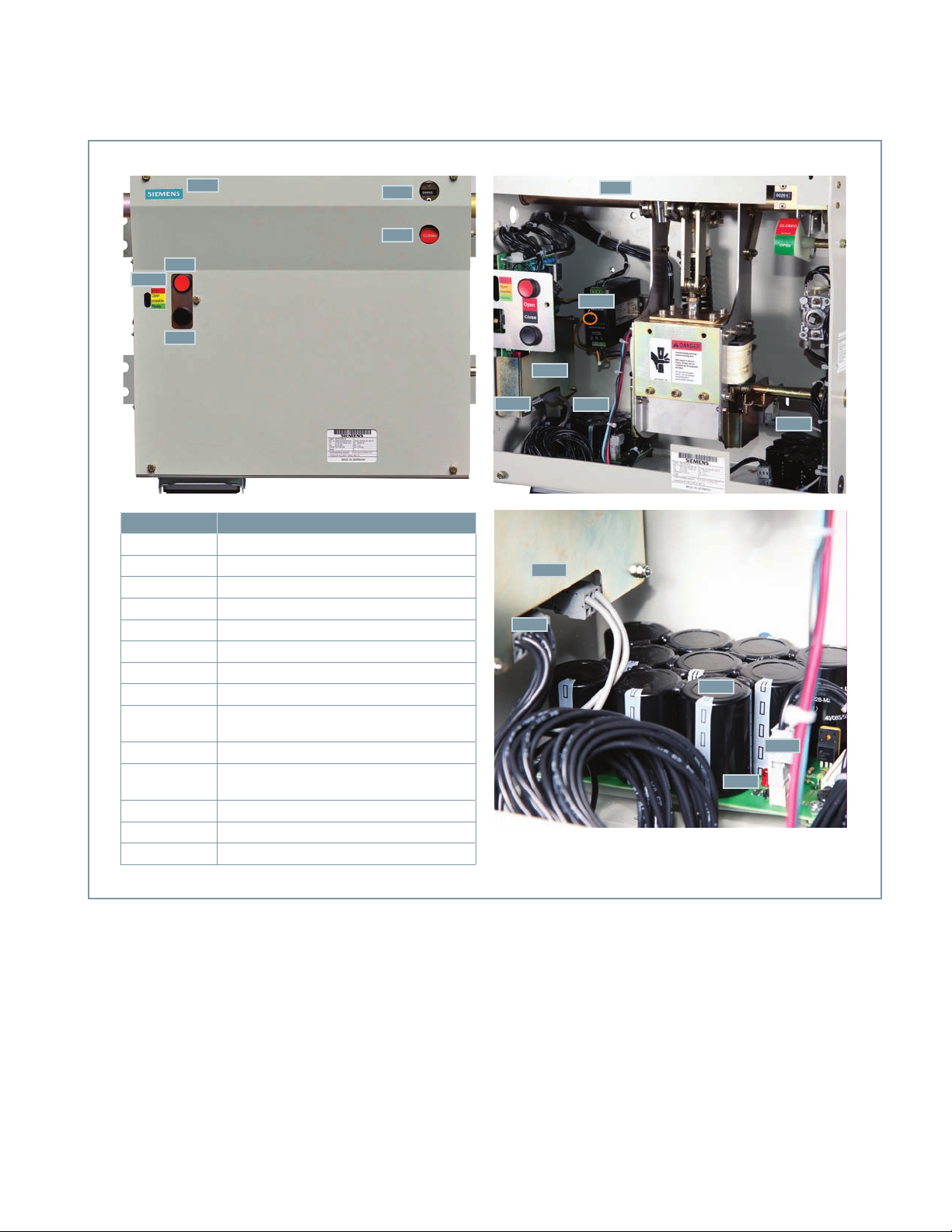
105.1
54.0
53.0
60.1
59.0
58.0
60.0
104.0
105.0
Identification Description
53.0 Close pushbutton (black)
54.0 Open pushbutton (red)
58.0 CLOSED/OPEN indicator
59.0 Operations counter
60.0 Mechanism housing
60.1 Mechanism housing cover
104.0 Power supply (green LED shown circled)
105.0 Controller board
105.1
105.2 Connector for capacitors
106.1
106.2 Capacitor
106.3 Connector (for each capacitor board)
106.4 Red LED capacitor discharge state
Light-emitting diodes (LEDs)
(red, yellow, green)
Capacitor board
(two or three depending upon rating)
105.2
105.2
106.1
106.1
105.0
106.2
106.3
106.4
Figure 2: Operator controls and discharging capacitors
7
Page 8
Hazardous voltages and stored energy.
Will cause death, serious injury or property damage.
Even if the circuit breaker and control circuits have been de-energized
for a long time, the power supply capacitors will maintain significant
stored energy. Always discharge the capacitors before maintenance.
Always de-energize and ground the equipment before maintenance.
Read and understand this instruction manual before using equipment.
Maintenance should be performed only by qualified personnel. The use
of unauthorized parts in the repair of the equipment or tampering by
unqualified personnel will result in dangerous conditions which will
cause death, severe injury or equipment damage. Follow all safety
instructions contained herein..
Stored energy and high speed moving parts.
Will result in serious injury. Fingers can be crushed by the magnetic
actuator.
Do not remove guard panel. Do not operate circuit breaker if guard
panel removed.
8
Page 9

Automatic capacitor charging
When control power is energized, the
controller board (105.0) executes a self-test
of the capacitors (106.2) and checks the
status of the capacitors (106.2). This self-test
runs automatically and regularly. The result of
the self-test is stored in the memory of the
controller board (105.0).
Capacitor charging check
The capacitor charging system of the circuit
breaker must be checked. Control power is
required for capacitor charging.
Note: A temporary source of control power
and test leads may be required if the control
power source has not been connected to the
circuit breaker. Refer to the specific wiring
information and rating label for your circuit
breaker to determine the voltage required
and the terminal points where the control
voltage signal should be applied. When
control power is connected to the circuit
breaker, the capacitors should automatically
charge.
1. Close the control power disconnect device
in the relay and control compartment to
energize the circuit breaker control circuit.
If not previously charged, the capacitors
should charge automatically.
2. Use the Close and Open pushbuttons on
the circuit breaker operating mechanism
(refer to Figure 3: Operator panel controls
on page 10) to first close, and then open
the circuit breaker contacts. Verify contact
positions visually by observing the OPEN/
CLOSED indicator on the circuit breaker.
When the capacitors are fully discharged
and control power is applied, the yellow
LED lights after approximately 25
seconds. The yellow LED turns off about
5-10 seconds later and the green LED
lights.
3. In step 2, when the Close pushbutton was
pressed, the circuit breaker should have
closed, and the capacitors should have
recharged automatically. The meaning of
the LEDs (105.1) on the controller board:
4. Perform the magnetic actuator-discharge
check.
a) Initial status: circuit breaker open.
b) Press red Open pushbutton (54.0).
c) Press black Close pushbutton (53.0).
d) Verify main contact status indicator
shows CLOSED.
e) Press red Open pushbutton (54.0)
again.
f) Verify main contact status indicator
shows OPEN.
5. De-energize the control power by opening
the control power disconnect device in
the relay and control compartment.
Remove the mechanism housing cover
sheet (60.1). Do not unplug connector
(106.3) from the capacitor boards, or
damage to the capacitor board or the
controller board may occur. Fast discharge
the capacitors (106.2) by unplugging the
connector (105.2) on the capacitor
controller board (105.0). During fast
discharge of the capacitors, a red LED on
each capacitor board will flash, indicating
that discharge is in process. The process is
complete when the red LED stops
blinking.
6. After the fast-discharge process, plug in
the connector (105.2) to the controller
board (105.0).
Final mechanical inspections without
control power
1. Make a final mechanical inspection of the
circuit breaker. Verify the contacts are in
the OPEN position.
2. Check visually that the connectors (106.3)
for each capacitor board are firmly
connected. Do not disconnect these
connections.
3. Reinstall the mechanism housing cover
sheet (60.1).
4. Check for loose hardware.
a) Green LED indicates ready (energy
sufficient for OPEN-CLOSE-OPEN cycle).
b) Yellow LED indicates open possible
(energy sufficient for OPEN operation).
c) Red LED indicates error (energy not
sufficient for operation).
9
Page 10
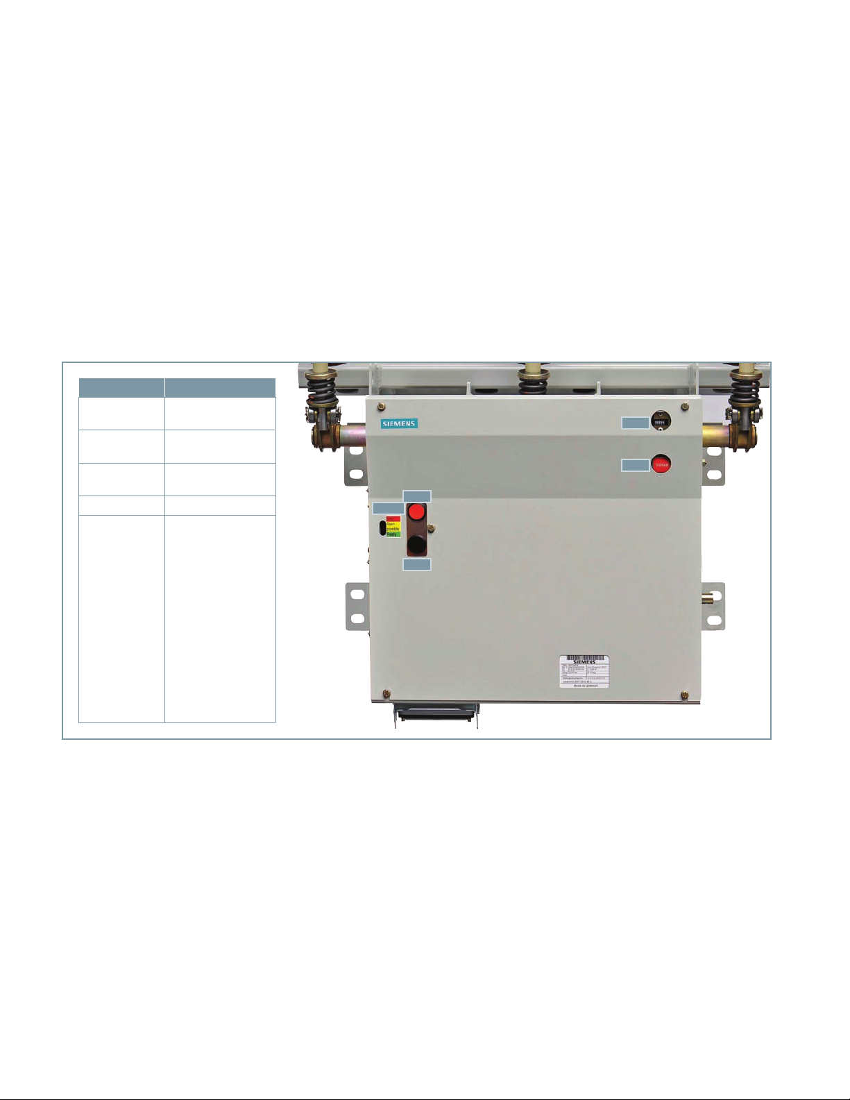
Identification Description
53.0
54.0
58.0
59.0 Operations counter
105.1
Close pushbutton
(black)
Open pushbutton
(red)
CLOSED/OPEN
indicator
LEDs:
Red LED indicates
error (energy not
sufficient for
operation).
Yellow LED indicates
open possible
(energy sufficient for
OPEN position).
Green LED indicates
ready (energy
sufficient for OPENCLOSE-OPEN cycle).
Vacuum interrupter/
operator
59.0
58.0
54.0
105.0
53.0
Figure 3: Operator panel controls
10
Page 11
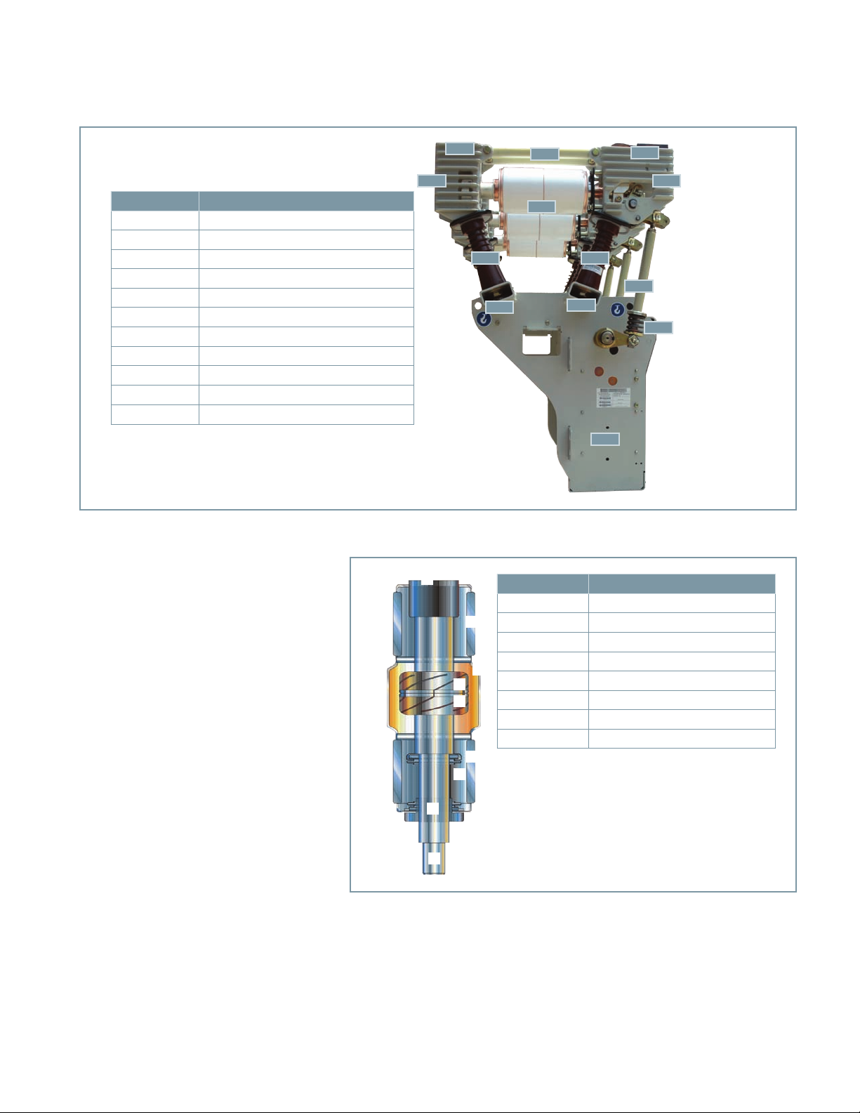
27.0
28.0
29.0
Identification Description
16.0 Pole support channels
16.1 Post insulator
20.0 Fixed-end pole head
27.0 Fixed-end connection pad
28.0 Strut
29.0 Moving-end connection pad
30.0 Vacuum interrupter
40.0 Moving-end pole head
48.0 Insulating coupler
49.0 Contact pressure spring
60.0 Mechanism housing
Introduction
The type 3AH35-MA vacuum circuit breaker
magnetic-actuator operator is intended for
stationary applications, such as the type
SDV7-MA outdoor distribution circuit breaker.
The type 3AH35-MA circuit breaker magnetic
actuator conforms to the requirements of
ANSI/IEEE standards, including C37.04,
C37.06, C37.09 and C37.010.
The circuit breaker includes three vacuum
interrupters, a magnetic-actuator operating
mechanism, necessary electrical controls and
an operator housing. In a typical installation,
insulating barriers may be located between
the vacuum interrupters.
This section describes the operation of each
major subassembly as an aid in the operation,
maintenance and repair of the circuit breaker.
20.0
A
G
40.0
30.0
16.116.1
48.0
16.0
Figure 4: Vacuum circuit breaker magnetic-actuator operator module
Identification Description
B
C
D
E
B
F
H
16.0
49.0
60.0
A Fixed contact-current connection
B Ceramic insulator
C Arc shield
D Fixed contact
E Moving contact
F Metal bellows
G Guide
H Moving contact-current connection
Vacuum interrupters
The operating principle of the vacuum
interrupter is simple. Figure 5: Vacuum
interrupter cutaway view is a section view of
a typical vacuum interrupter. The entire
assembly is sealed after a vacuum is
established. The vacuum interrupter
stationary contact is connected to the fixedend pole head (20.0) of the circuit breaker.
Figure 5: Vacuum interrupter cutaway view
11
Page 12
48.6
49.0
63.3
Identification Description
48.6 Angled lever
49.0 Contact pressure spring
63.1 Lever - phase C
63.3 Lever - phase A
63.5 Lever - phase B
Figure 6: Vacuum circuit breaker magnetic-actuator operator module
49.0
63.5
The vacuum interrupter movable contact is
connected to the flexible shunt (29.1)
associated with the other pole head and to
the driving mechanism of the circuit breaker.
The metal bellows provide a secure seal
around the movable contact, preventing loss
of vacuum while permitting motion of the
movable contact along the axis of the
vacuum interrupter.
When the two contacts separate, an arc is
initiated that continues conduction up to the
following current zero. At current zero, the
arc extinguishes and any conductive metal
vapor that has been created by and supported
the arc condenses on the contacts and on the
surrounding arc shield. Contact materials and
configuration are optimized to achieve arc
motion and to minimize switching
disturbances.
63.1
49.0
Primary connections
Figure 4: Vacuum circuit breaker magneticactuator operator module on page 11
illustrates the pad provision to accept the
primary connections. Each circuit breaker has
three connection pads at the fixed end of the
vacuum interrupter, and three connection
pads on the flexible connectors that are
associated with the movable contact of the
vacuum interrupter. Interconnecting bus in
the circuit breaker enclosure connects these
connection pads to the roof bushing
terminals. Bolting hardware is M12 x 1.75
grade 8. Torque M12 bolts to 52 ft-lb (70
Nm).
Phase barriers (if applicable)
For certain ratings, barriers of glass-polyester
insulating material are attached to the circuit
breaker and provide suitable electrical
insulation between the vacuum interrupter
and primary conductors and the enclosure.
Magnetic actuator operating mechanism
The energy needed for closing and tripping is
stored in two or three capacitor banks (106.0)
(depending on circuit breaker rating) charged
to approximately 160 V. The self-discharging
function is activated by removing the
connector (105.2) of the controller board
(105.0). Do not unplug connector (106.3)
from the capacitor boards, or damage to the
capacitor board or the controller board may
occur. The capacitors are charged
automatically when control power is applied.
From fully discharged condition, the
capacitors are fully charged in approximately
30-35 seconds.
The capacitor charge is monitored constantly
by the controller board (105.0). If the control
power source fails, the capacitors can initiate
one open operation initiated by the operatormounted pushbutton (54.0). This last
operation must be initiated within 300 s after
loss of control power supply. Within 300 s
after loss of operator control power, the
circuit breaker can perform one open
operation initiated by a remote command if
the remote command is from a wet
(powered) contact.
The green LED, which indicates that energy is
sufficient for an OPEN-CLOSE-OPEN operation
is illuminated as long as the voltage of the
capacitors is greater or equal to 150 V.
12
Page 13

Vacuum interrupter/operator module
The vacuum interrupter/operator module
consists of the three poles, each with its
vacuum interrupter and primary insulators,
mounted above the common magnetic
actuator operating mechanism housing
(60.0). This module is shown in Figure 6:
Vacuum circuit breaker magnetic-actuator
operator module on page 12.
Construction
Each of the circuit breaker poles is fixed to the
pole support channel (16.0) by two cast-resin
insulators. The insulators also connect to the
fixed- and moving-end pole heads (40.0) that
in turn support the ends of the vacuum
interrupter. The pole supports are aluminum
castings or sheet steel (for 15.5 kV and
27.6 kV up to 25 kA). Refer to Figure 3:
Operator panel controls on page 10 and
Figure 4: Vacuum circuit breaker magneticactuator operator module on page 11, Figure
7: Pole assembly on page 14 and Figure 8:
Magnetic-actuator operating mechanism on
page 15.
The magnetic actuator mechanism and all the
control and actuating devices are installed in
the operator housing.
The CLOSE-OPEN indicator, Open pushbutton,
Close pushbutton, the LEDs on the controller
board and the operation counter are located
on the front of the mechanism housing.
The control connector for the control and
signalling cables is a multi-contact plug. The
mating control plug wiring connects to the
terminal blocks in the relay and control
compartment.
Circuit breaker pole (refer to Figure 7: Pole
assembly on page 14)
The vacuum interrupter is bolted to the fixedend pole head (20.0), which is rigidly
connected to the pole support channel (16.0)
by the post insulator (16.1). The moving
contact end of the vacuum interrupter is
stabilized against lateral forces by a centering
ring (28.1) on the moving-end pole head
(40.0). The external forces due to switching
operations and the contact pressure are
absorbed by the struts (28.0).
Current-path assembly (refer to Figure 7:
Pole assembly on page 14)
The current-path assembly consists of the
fixed-end pole head (20.0), the stationary
contact and the moving contact, plus a
flexible shunt (29.1) between the moving
contact terminal clamp (29.2) and the
moving-end connection pad (29.0).
Vacuum interrupter (refer to Figure 7: Pole
assembly on page 14)
The moving-contact motion is aligned and
stabilized by a guide bushing. The metal
bellows follows the travel of the contact and
seals the vacuum interrupter against the
surrounding atmosphere.
Switching operation
The sequence of actions involved in various
switching operations are described in this
section. Refer to Figure 7: Pole assembly on
page 14 and Figure 8: Magnetic-actuator
operating mechanism on page 15.
When a closing command is initiated, the
controller board (105.0) checks the circuit of
the magnetic actuator’s coil (101.3) for
integrity. After the integrity check has been
proven satisfactory, the capacitors (106.2)
power the magnetic actuator (101.0). This
process is monitored by the controller board
(105.0). The electrical current in the coil
(101.3) generates a magnetic field. An
attractive force causes the anchor (101.4)
moving upwards.
The coupling rod (62.8) moves upwards by
compressing the opening springs (64.0) by
means of the jack shaft (63.0). The contact
pressure springs (49.0) are compressed and
the insulating couplers (48.0) are moved
upwards. Through the angled levers (48.6)
the contacts in the vacuum interrupter (30.0)
are closed.
The forces that occur when the action of the
insulating coupler (48.0) is converted into the
action of the moving contact along the axis of
the vacuum interrupter are absorbed by the
guide link (48.9) that pivots on the movingend pole head and the eye bolt.
13
Page 14
In the closed state, the necessary contact
pressure is maintained by the contact
pressure springs (49.0) and the atmospheric
pressure. The magnetic actuator maintains a
stable closed position without supplemental
energy input. The contact pressure spring
automatically compensates for arc erosion,
which is very small.
When a opening command is initiated, the
controller board (105.0) checks the circuit of
the magnetic actuator’s coil (101.3) for
integrity. After the integrity check has been
proven satisfactory, the capacitors (106.2)
power the magnetic actuator coil (101.3)
with a reverse current. This opposes the
attactive force between the magnetic
actuator (101.0) and the permanent magnet.
Due to the energy stored in the contact
pressure springs (49.0) and the opening
spring (64.0), the magnetic actuator’s anchor
(101.4) is pushed downwards. This opening
process is supported by the opening spring
(64.0). In the OPEN position the opening
spring assures that the ambient pressure does
not close the contacts in the vacuum
interrupters (30.0).
Operating mechanism
The operating mechanism is comprised of the
mechanical and electrical components
required to:
1. Charge the capacitors for providing
sufficient electrical energy to move the
magnetic actuator and close or open the
circuit breaker.
2. Mechanisms to release closing and
opening actions.
3. Means of transmitting force and motion
to each of the three vacuum interrupters.
4. Operate all these functions automatically
through the capacitors (106.2), the
controller board (105.0). auxiliary switch
3SV9 (68.0), the lock out switch (114.0)
and the opening spring (64.0).
5. Provide indication of the circuit breaker
status (OPEN/CLOSED), indicate capacitor
energy status (green LED indicates ready,
yellow LED indicates OPEN possible and
red LED indicates error) and number of
operations.
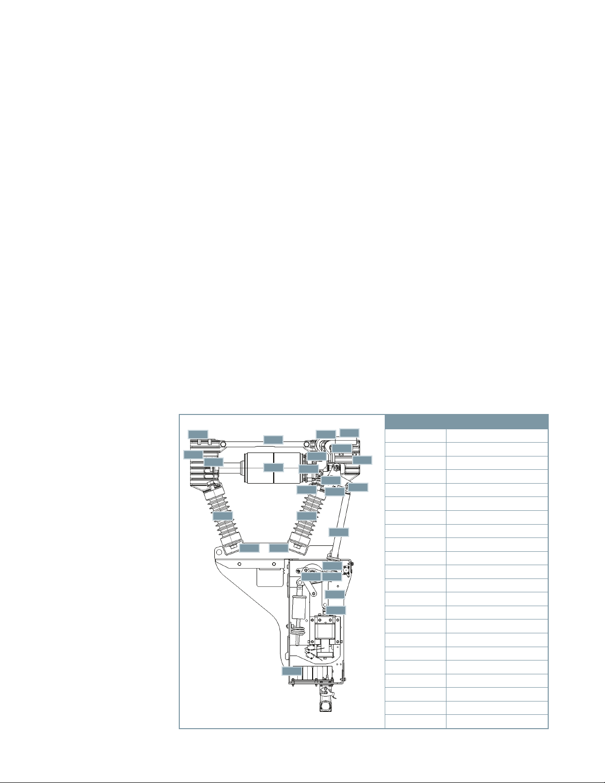
Figure 7: Pole assembly
27.0
20.0
31.0
16.1 16.1
28.0
30.0
16.016.0
60.0
36.0
28.1
63.0
29.2
29.1
48.6
49.0
64.3
48.9
48.0
62.9
62.8
29.1
29.0
40.0
48.9
Identification Description
16.0 Pole support channels
16.1 Post insulator
20.0 Fixed-end pole head
27.0 Fixed-end connection pad
28.0 Strut
28.1 Centering ring
29.0 Moving-end connection pad
29.1 Flexible shunt
29.2 Terminal clamp
30.0 Vacuum interrupter
31.0 Fixed contact
36.0 Moving contact
40.0 Moving-end pole head
48.0 Insulating coupler
48.6 Angled lever
48.9 Guide link
49.0 Contact pressure spring
60.0 Mechanism housing
62.8 Coupling rod
62.9 Coupling link
63.0 Jack shaft
64.3 Lever
14
Page 15
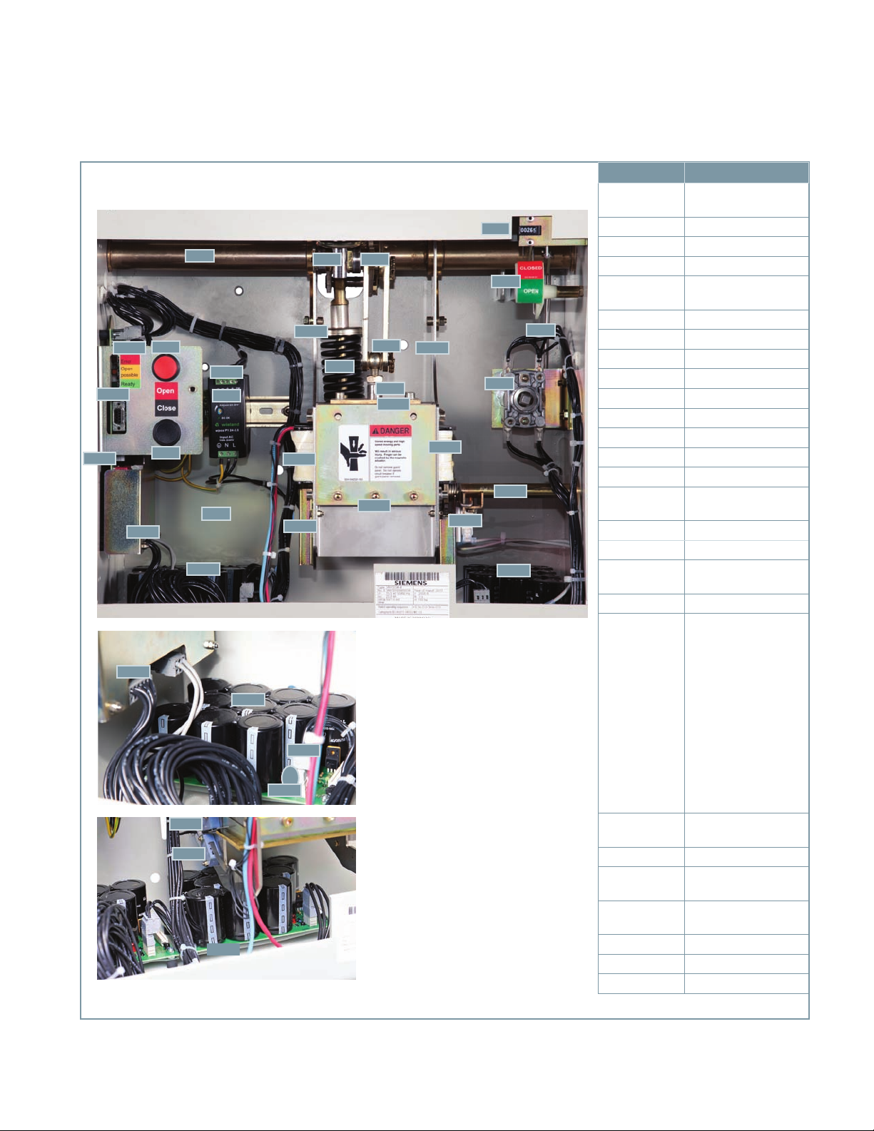
Figure 8: Magnetic-actuator operating mechanism
Circuit breaker shown in OPEN position.
105.1
105.0
109.0
105.2
105.2
63.0
54.0
104.0
54.1
53.0
60.0
106.0
106.1
106.4
113.0
113.0
106.1
63.5 64.3
101.1
101.3
113.0
106.3
64.0
62.9
101.5
62.8
101.0
101.1
103.0
114.0
59.0
58.0
68.0
102.1
106.0
68.1
Identification Description
53.0
54.0 Open pushbutton (red)
58.0 CLOSED/OPEN indicator
59.0 Operations counter
60.0
62.8 Coupling rod
62.9 Coupling link
63.0 Jack shaft
63.5 Lever phase B
64.0 Opening spring
64.3 Lever
68.0 Auxiliary switch
101.0 Magnetic actuator
101.1 Side plate
101.3
101.5 Safety guard
102.1 Manual opening shaft
104.0
105.0 Controller board
105.1
105.2
106.1 Capacitor board
106.3
106.4
109.0 Control panel
113.0 Position switches
114.0 Lockout switch
Close pushbutton
(black)
Operator mechanism
housing
Coil of magnetic
actuator
Power supply for
controller board
LEDs:
Red LED indicates error
(energy not sufficient
for operation).
Yellow LED indicates
open possible (energy
sufficient for OPEN
position).
Green LED indicates
ready (energy sufficient
for OPEN-CLOSE-OPEN
cycle).
Connector (disconnect
to discharge capacitors)
Connector for each
capacitor board
Red LED - capacitor
discharge state
15
Page 16

Construction
The essential parts of the operating
mechanism are shown in Figure 8: Magneticactuator operating mechanism on page 15.
The essential parts of the magnetic actuator
(101.0) are the side plates, cover plate,
permanent magnets, coupling rod, coil,
armature parts and bearing plate for
armature.
The magnetic actuator (101.0) is connected
by the side plates with the mechanism
housing (60.0). Also, the magnetic actuator
(101.0) secures to the jack shaft (63.0). The
magnetic actuator (101.0) requires no
maintenance.
If the circuit breaker is stored for a long time
without control power, the capacitors will
fully discharge. Charge the capacitors at least
every two years for a minimum of three
hours. Apply control power to the power
terminals as shown on the drawings specific
to the order on which the circuit breaker was
supplied. Refer to the example of circuit
diagram shown in Figure 14 on page 24.
Mode of operation
The capacitors have been charged, the
mechanism is ready for an operation at any
time. This is indicated by the green LED
(105.1) on the front panel. If the control
voltage fails, the stored energy is sufficient
for one open operation initiated by the
operator-mounted Open pushbutton (54.0)
within five minutes. Within five minutes after
loss of operator control power, the circuit
breaker can perform one open operation
initiated by a remote command if the remote
command is from a wet (powered) contact.
Closing
There are two different closing operations
possible:
Remote (electrical)
Local (electrical) (by pressing the
pushbuttons).
When a close command is initiated, the
capacitors supply current to the actuator coil,
creating an electromagnetic field. This field
adds to the magnetic field of the permanent
magnets. As a result, the coupling rod (62.8)
moves upward. In turn, this transfers force to
the jack shaft (63.0) by means of the
coupling link (62.9), closing the circuit
breaker. Simultaneously, the opening spring
(64.0) is compressed.
Trip-free function for the type SDV7-MA
outdoor distribution circuit breaker
For the type SDV7-MA outdoor distribution
circuit breaker, the trip-free function is
embedded in the controller electronics.
Opening
When an opening command has been given,
a reverse current is supplied to the magnectic
actuator coil (101.3). This cancels the
attractive force between the magnetic
actuator (101.0) and the permanent magnet.
Due to the stored energy of the contact
pressure spring (49.0), the magnetic
actuator’s armature is pushed downwards.
This opening process is supported by the
opening spring (64.0). In the OPEN position,
the opening spring assures that the ambient
atmospheric pressure does not close the
contacts in the vacuum interrupters (30.0).
16
Page 17

Detail A
60.0
Detail B
60.0
101.0
101.3
102.3
102.1
114.0
Identification Description Identification Description
60.0 Mechanism housing 102.3 Interlock lever
101.0 Magnetic actuator
102.1 Manual opening shaft
Figure 9: Manual opening mechanism components
Manual opening
The manual opening lever can be used to
open the circuit breaker manually, and can
also be used to block the circuit breaker in the
OPEN position. The manual opening lever is
located to the right side of the operator, on
the exterior of the type SDV7-MA circuit
breaker enclosure.
Figure 9 shows the mechanism internal
components that are part of the manual
opening system. In detail A, the interlock
lever (102.3) is shown in the normal position.
The shaft (102.1) of the manual opening
114.0 Lockout switch
If the shaft is returned to the normal position,
electrical closing and opening operations can
be performed. If instead, the manual opening
shaft is rotated 90°, the interlock lever
(102.3) prevents closing by mechanically
blocking movement of the magnetic actuator.
In this position, position switch S6 (114.0)
continues to disable electrical operation.
When maintenance is to be performed,
operation of the circuit breaker can be
prevented by installing a padlock on the
external manual opening lever. Refer to
Figure 10: Use of manual opening lever.
lever is connected by a spring to the interlock
lever (102.3). When the manual opening
lever is rotated a few degrees, electrical
opening is disabled by position switch S6
(114.0). On further shaft rotation, the circuit
breaker opens.
101.0
101.3
102.3
102.1
114.0
Figure 10: Use of manual opening
lever
17
Page 18

Figure 11: Operating mechanism section diagram
Circuit breaker OPEN Circuit breaker CLOSED
48.0
64.3
64.0
113.1
113.2
63.0
62.9
62.8
101.2
101.3
101.4 101.1
49.0
63.5
48.0
101.0
64.3
64.0
113.1
113.2
63.0
101.2
49.0
63.5
62.9
62.8
101.0
101.3
101.4
101.1
18
Identification Description
48.0 Insulating coupler
49.0 Contact pressure spring
62.8 Coupling rod
62.9 Coupling link
63.0 Jack shaft
63.5 Lever - phase B
64.0 Opening spring
64.3 Lever
101.0 Magnetic actuator
101.1 Side plates
101.2 Permanent magnet
101.3 Coil
101.4 Anchor
113.1 Position switch (CLOSED) S4
113.2 Position switch (OPEN) S5
Page 19

Closing (electrical) using pushbutton or external command
Closing
Control
voltage applied.
Figure 12: Operator sequential flow diagram
Initialization
routine runs.
Charging of capacitors
(indicated by LEDS on the front panel:
on
yellow
yellow
Circuit
breaker
closed.
No action! Magnetic actuator
Capacitors
not charged.
Position switch S4
(113.1) closes.
Opening (electrical) using pushbutton or external command
Open
command.
off
command
when
No action!
greenon)
Circuit
breaker
open.
energized through
closed lockout
Hand-off lever in
NORMAL position.
switch S6 (114.0).
Magnetic field,
together with
electromagnetic
field, causes
coupling rod to
move upward.
Opening using manual opening lever
Open using
manual opening lever.
Circuit breaker
closes.
magnetic actuator with reverse current.
Electromagnetic field cancels magnetic
opening spring open circuit breaker.
Position switch S5
(113.2) closes.
The capacitors feed the coil of the
field; contact pressure springs and
Circuit breaker
opens.
Rotation of the manual opening shaft 5°
opens the position switch S6 (114.0) and
interrupts the circuit of the magnetic
actuator coil. Local or remote tripping is
disabled.
Rotation of the manual opening shaft
beyond 5° overcomes the attractive force
of the permanent magnet.
Circuit breaker opens due to stored energy
in contact pressure springs and opening
spring, moving the magnetic actuator
anchor to the lower position. The opening
spring maintains the anchor in this
position.
Rotation of the manual opening shaft to
90° mechanically blocks the magnetic
actuator, preventing closing.
19
Page 20

Figure 13: Magnetic actuator controller flow diagram
Part 1: Controller initialization upon control power energization
Control
voltage applied.
Microcontroller performs internal self-test.
Validation of configuration values.
Check of actuator position.
Charging capacitors.
Check of capacitor voltage.
Check of coil circuit.
Status signalization via LED (Green LED
indicates read, yellow LED indicates OPEN
possible, red LED indicates error).
Part 2: Cyclic self-test (each millisecond)
Internal level 24 V present.
Check communications port for input.
Test capacitor capacity (every 7 days).
Cyclic self-test, ready for operation-see
Check internal power system
Check of actuator position.
Check of capacitor voltage.
Part 2.
No
command input.
Internal level 24 V not present.
Within 300 s from loss of control power,
an OPEN operation can be initiated using
pushbutton. During this time,
microcontroller operation is maintained
using stored energy from the capacitors.
Check of actuator position.
Check of capacitor voltage.
Cyclic self-test is initiated every 150 ms
(energy saving mode).
20
Page 21

Part 3: CLOSE command using local pushubutton or external command
CLOSE
command.
Verification:
Command duration >10 ms.
Current actuator position is OPEN.
Check of coil circuit.
Check of capacitor voltage.
Switch on the coil to pull the anchor in
upper position until the CLOSED position
is reached. Automatically removed if
CLOSED position is not reached with
100 ms.
CLOSED position is reached
within 100 ms.
The anchor moves up, rotating the jack
shaft via the coupling rod. The circuit
breaker closes, compressing the contact
pressure springs and the opening spring.
The permanent magnet maintains the
CLOSED position.
Figure 13: Magnetic actuator controller flow diagram (continued)
CLOSED position is not reached
within 100 ms.
Mis-operation: if CLOSED position is not
reached within 100 ms, the red LED
illuminates to indicate an error. A self-test
of electronics, coil and capacitors is
initiated. If no fault is detected, the
system is ready for closing after 5 s.
Part 4: OPEN command using local pushubutton or external command
If control voltage has been been missing
for 300 s or more, electrical opening is not
possible; circuit breaker can be opened
using manual opening lever.
Command duration >10 ms.
Current actuator position is CLOSED.
Check of capacitor voltage.
Switch on the coil for compensation of the
permanent magnetic field until the OPEN
position is reached. Automatically
removed if OPEN position is not reached
OPEN position is reached
within 100 ms.
Circuit breaker opens due to stored energy
in contact pressure springs and opening
spring, moving the magnetic actuator
anchor to the lower position. The opening
spring maintains the anchor in this
position.
OPEN
command.
Verification:
Check of coil circuit.
with 100 ms.
OPEN position is not reached
within 100 ms.
Mis-operation: if OPEN position is not
reached within 100 ms, the red LED
illuminates to indicate an error. A self-test
of electronics, coil and capacitors is
initiated. If no fault is detected, the
system is ready for opening after 5 s.
21
Page 22

Table 1: Controller capacitor monitoring - LED status
Energy Circuit breaker position Alarm status
Circuit capacitor
condition
Energy sufficient for
OPEN-CLOSE-OPEN
operation
Energy sufficient for
CLOSE-OPEN
operation
Energy sufficient for
OPEN operation
Energy not sufficient
for any operation
CLOSED local monitoring LED status
Remote output relay (NO contact)
Green LED ON
Yellow LED OFF
"Ready" status contact
(ST2-1) CLOSED
"Open possible" status
contact
(ST2-2) OPEN
Green LED OFF
Yellow LED ON Yellow LED ON
"Ready" status contact
(ST2-1) OPEN
"Open possible" status
contact
(ST2-2) CLOSED
Green LED OFF
Yellow LED OFF Yellow LED OFF
"Ready" status contact
(ST2-1) OPEN
"Open possible" status
contact
(ST2-2) OPEN
OPEN-CLOSE-OPEN
operation possible
OPEN operation
possible
No operation possible
OPEN local monitoring LED status
Green LED ON
Yellow LED OFF
"Ready" status contact
(ST2-1) CLOSED
"Open possible" status
contact
(ST2-2) OPEN
Green LED OFF
"Ready" status contact
(ST2-1) OPEN
"Open possible" status
contact
(ST2-2) CLOSED
Green LED OFF
"Ready" status contact
(ST2-1) OPEN
"Open possible" status
contact
(ST2-2) OPEN
OPEN-CLOSE-OPEN
operation possible
Blocked OPEN
position, no CLOSE
permitted because
energy not sufficient
for CLOSE-OPEN
No operation possible
Error:
Local red LED alarm
Red LED OFF
Alarm status contact
(ST2-3) OPEN
Red LED OFF
Alarm status contact
(ST2-3) OPEN
Red LED OFF
Alarm status contact
(ST2-3) OPEN
Red LED OFF
Alarm status contact
(ST2-3) OPEN
22
Page 23

The schematic shown in Figure 14: Typical
circuit breaker schematic on page 24 is
intended to aid in understanding the
mechanism operation discussed in this
instruction manual. Refer to the schematic
diagram furnished with your circuit breaker
for specific information.
Also, refer to Figure 12: Operator sequential
flow diagram on page 19 and Figure 13:
Magnetic actuator controller flow diagram
on pages 20-21.
Electrical operations are performed through
the magnetic actuator controller using the
stored energy in the capacitor boards.
Local electrical operation is initiated using
the black Close (53.0) or Open (54.0)
pushbuttons (refer to Figure 3: Operator
panel controls on page 10), designated as
S2 and S3 in Figure 14: Typical circuit
breaker schematic on page 24. External
commands (for example, from protective
relays or remote circuits) for closing or
opening can be connected through
terminals A2/C3 and A4/D3 as shown.
Electronic controller binary inputs/
outputs
The status output contacts (for controller
energy status and circuit breaker position)
available from the electronic controller are
shown on the schematic diagrams (Figures
14 on page 24 and 15 on page 25). These
status output contacts have ratings as
follows:
N.O. contacts (terminals 1-6, 2-6, 4-6 and
5-6 on -ST2):
Switching capability: 375 VA ac/
90 W dc (resistive)
Current rating: 3 A
Voltage rating: up to 240 Vac or
250 Vdc.
N.C. contacts (terminals 3-6 on -ST2):
Switching capability: 5 A@24 Vdc;
0.4 A@48 Vdc; 0.2 A@125 Vdc;
0.15 A@250 Vdc (all resistive)
The alarm contact (ST2-3/ST2-6 in Figure
15: Controller schematic on page 25) opens
approximately 15 seconds after an alarm
condition begins, and then cycles between
open (alarm) for 15 seconds and closed
(normal) for 5 seconds until power is
insufficient to keep the electronic controller
functional. At this point, the alarm contact
closes and remains closed until control
power is restored.
The binary inputs (for electrical closing or
opening from pushbuttons, protective
relays, etc.) have an input resistance of 300
kΩ, and have a threshold of response as
follows:
For high range (85-265 Vac or 95-
250 Vdc) power supply input voltage is
approximately 68 Vac or 68 Vdc
For low range (20-52 Vac or 18-75 Vdc)
power supply input voltage is
approximately 17 Vac or 17 Vdc.
For increased security of close and open
operations, the control signal to initiate a
close or open action must exceed the
threshold response voltage above for at
least 10 ms to be considered a valid
command. Commands which do not persist
for at least 10 ms are ignored by the
microprocessor. To allow for microprocessor
processes and circuit breaker function, a
minimum signal duration of 100 ms is
required.
Auxiliary switch (52a/b)
Figure 8: Magnetic-actuator operating
mechanism on page 15 shows the circuit
breaker mounted auxiliary switch (68.0).
This switch provides auxiliary contacts for
use in control and protection circuits.
Contacts are available for use in relaying
and external logic circuits. This switch is
driven by linkage (68.1) connected to the
jack shaft (63.0). The auxiliary switch
contains both “b” (normally closed) and “a”
(normally open) contacts. When the circuit
breaker is open, the “b” contacts are closed
and the “a” contacts are open.
Current rating: 3 A
Voltage rating up to 240 Vac or
250 Vdc.
23
Page 24

Figure 14: Typical circuit breaker schematic
Legend
01/C Control switch close (remote)
01/T Control switch trip (remote)
08 Power disconnect
52a Auxiliary switch, OPEN when circuit breaker is OPEN
52b Auxiliary switch, CLOSED when circuit breaker is OPEN
G Green indicating light (remote)
R Red indicating light (remote)
W White indicating light (remote)
XO Plug connector (operator connections)
52a and 52b spare contacts (standard)
Power
supply
Notes
Schematics are shown with circuit
breaker OPEN.
Protective relays
Operator
Status
Ready for CLOSEOPEN (N.O.)
Ready for OPEN (N.O.)
24
Power
supply
Close
command
Operator
Open
command
Operator
Not ready (alarm) (N.C.)
Circuit breaker
CLOSED (N.O.)
Circuit breaker OPEN (N.O.)
Common
Page 25

Figure 15: Controller schematic
Electronic
controller
Ground
+24 Vdc
Green LED (N.O.)
Yellow LED (N.O.)
Red LED (alarm) (N.C.)
Circuit breaker
CLOSED (N.O)
Circuit breaker
OPEN (N.O)
Common
+160 Vdc
+160 Vdc
Ground
Ground
Discharge
Discharge
Magnetic-actuator coil
64-pin
plug (XO)
Power
supply
Coil Sense coil
Unused
Magnetic-actuator coil
OPEN position switch
CLOSED position switch
+24 Vdc
+24 Vdc
Unused
OPEN pushbutton
CLOSE pushbutton
Sense coil
Sense coil
CLOSE command
CLOSE command
Unused
OPEN command
OPEN command
Mechanical
lockout
Magnetic actuator
OPEN
CLOSED
25
Page 26

Maintenance
Failure to maintain the equipment can result in death, serious injury, property damage or product
failure, and can prevent successful functioning of connected apparatus.
The instructions contained herein should be carefully reviewed, understood and followed.
The maintenance tasks in Table 2 must be performed regularly.
Note: A preventive
maintenance program is not
intended to cover
reconditioning or major
repair, but should be
designed to reveal, if
possible, the need for such
actions in time to prevent
malfunctions during
operation.
Introduction and maintenance intervals
Periodic inspections and maintenance are
essential to safe and reliable operation of
the circuit breaker.
When circuit breakers are operated under
“usual service conditions,” maintenance and
lubrication are recommended at five-year
intervals for the type SDV7-MA outdoor
distribution circuit breaker, or at the number
of operations indicated in Table 23:
Maintenance and lubrication schedule on
page 29. “Usual” and “unusual” service
conditions for outdoor medium-voltage
circuit breakers are defined in ANSI/IEEE
C37.04, section 4 and ANSI/IEEE C37.010,
section 4. Generally, “usual service
conditions” are defined as an environment
where the equipment is not exposed to
excessive dust, acid fumes, damaging
chemicals, salt air, rapid or frequent
changes in temperature, vibration, high
humidity and extreme temperatures.
The definition of “usual service conditions”
is subject to a variety of interpretations.
Because of this, you are best served by
adjusting maintenance and lubrication
intervals based on your experience with the
equipment in the actual service
environment.
Regardless of the length of the maintenance
and lubrication interval, Siemens
recommends that circuit breakers should be
inspected and exercised annually.
For the safety of maintenance personnel as
well as others who might be exposed to
hazards associated with maintenance
activities, the safety related work practices
of NFPA 70E (especially chapters 1 and 2)
should always be followed when working on
electrical equipment.
Maintenance personnel should be trained in
the safety practices, procedures and
requirements that pertain to their respective
job assignments.
This instruction manual should be reviewed
and retained in a location readily accessible
for reference during maintenance of this
equipment.
The user must establish a periodic
maintenance program to ensure trouble-free
and safe operation. The frequency of
inspection, periodic cleaning and a
preventive maintenance schedule will
depend upon the operation conditions.
NFPA publication 70B, “Electrical equipment
maintenance” may be used as a guide to
establish such a program.
26
Page 27

Hazardous voltages and stored energy.
Will cause death, serious injury or property damage.
Even if the circuit breaker and control circuits have been de-energized
for a long time, the power supply capacitors will maintain significant
stored energy. Always discharge the capacitors before maintenance.
Always de-energize and ground the equipment before maintenance.
Read and understand this instruction manual before using equipment.
Maintenance should be performed only by qualified personnel. The use
of unauthorized parts in the repair of the equipment or tampering by
unqualified personnel will result in dangerous conditions which will
cause death, severe injury or equipment damage. Follow all safety
instructions contained herein.
Stored energy and high speed moving parts.
Will result in serious injury. Fingers can be crushed by the magnetic
actuator.
Do not remove guard panel. Do not operate circuit breaker if guard
panel removed.
NOTICE
Electrostatic discharge hazard.
May result in damage to printed circuit boards.
To prevent damage to printed circuit boards, discharge any static
electrical charges on hands or tools by touching grounded surfaces of
the enclosure before touching capacitors (106.2), capacitor board
(106.1) or controller board (105.0) and before disconnecting any
connector plugs.
27
Page 28

Recommended hand tools
Metric hardware is used on these circuit
breakers.
The following list of hand tools describes
those normally used in disassembly and
re-assembly procedures:
Open-end wrenches: 3, 5.5, 7, 8, 10, 13,
17, 19 and 24 mm
Sockets: 7, 8, 10, 13 and 17 mm
Socket: 36 mm (used for replacing post
insulators (16.1))
Deep sockets: 19 and 24 mm
Hex keys: 5, 6, 8 and 10 mm
Torque wrench: 0-150 Nm
(0-100 ft-lbs)
Screwdrivers: 0.032 x 1/4 in wide and
0.055 x 7/16 in wide
Pliers
Light hammer
Inspection items and tests
Primary-power path checks
Cleanliness check
Inspection of flexible connectors
Magnetic-actuator operator-mechanism checks
Maintenance and lubrication
Fastener check
Capacitor charging check
Contact-erosion check
Electrical-control checks
Wiring and terminals checks
Capacitor charging check
Electrical close and trip check
Vacuum-integrity check
High-potential test
Insulation test
Contact-resistance test
Inspection and cleaning of circuit breaker insulation
Functional tests
Mechanic’s mirror
Flashlight
Drift pins: 1/8, 3/16 and 1/4 in
Retaining ring plier (external type, tip
diameter 0.038 in).
Recommended maintenance and
lubrication
Periodic maintenance and lubrication should
include all the tasks shown in Table 2.
Recommended procedures for each of the
listed tasks are provided in this section of
the instruction manual.
The list of tasks in Table 2: Maintenance
tasks does not represent an exhaustive
survey of maintenance steps necessary to
ensure safe operation of the equipment.
Particular applications may require further
procedures. Should further information be
desired or should particular problems arise
that are not covered sufficiently for the
user’s purposes, the matter should be
referred to the local Siemens sales office.
Table 2: Maintenance tasks
Checks of the primary power path
The primary power path consists of the
three vacuum interrupters, the three fixedend and three moving-end connections to
the enclosure bus system. These
components are checked for cleanliness and
condition. The vacuum interrupters are also
checked for vacuum integrity.
The contact erosion check is performed with
the contacts in the vacuum interrupter
(30.0) in the CLOSED position.
The vacuum-integrity check is usually
performed in conjunction with the highpotential tests.
28
Page 29

The use of unauthorized parts in the repair of the equipment, or tampering by unqualified
personnel can result in hazardous conditions, that can result in death, serious injury or
property damage.
Follow all safety instructions contained herein.
Circuit
breaker
type
SDV7-MA
Table 3: Maintenance and
lubrication schedule
Number of
years/closing
operations
(whichever
comes first)
5-years/
10,000
operations
Cleanliness check
Figure 4: Vacuum circuit breaker magneticactuator operator module on page 11 is a
side view of the circuit breaker with the
insulating barriers removed (if furnished) to
show the vacuum interrupters, and the
fixed-end and moving-end connection pads
(29.0).
All of these components must be clean and
free of dirt or any foreign objects. Use a dry
lint-free cloth. For stubborn dirt, use a clean
cloth dipped in isopropyl alcohol (except for
the vacuum interrupters). For stubborn dirt
on a vacuum interrupter use a cloth and
warm water and a small amount of mild
liquid-household detergent as a cleaning
agent. Dry thoroughly using a dry lint-free
cloth.
Inspection of flexible connectors
Inspect the flexible connectors that connect
the movable contacts of the vacuum
interrupters to the moving-end connection
pad (29.0) for tightness and absence of
mechanical damage, burning or pitting.
Checks of the magnetic-actuator operator
mechanism
The magnetic-actuator operator checks are
divided into mechanical and electrical
checks for simplicity and better
organization. This first series of checks
determine if the basic mechanism is clean,
lubricated and operates smoothly. The
contact-erosion check of the vacuum
interrupter is also performed during these
tasks.
Maintenance and lubrication
Table 3 gives the recommended
maintenance intervals for circuit breakers.
These intervals assume that the circuit
breaker is operated under “usual service
conditions” as discussed in ANSI/IEEE
C37.04, section 4 and elaborated in ANSI/
IEEE C37.010, section 4 for outdoor
distribution circuit breakers. The
maintenance and lubrication interval is the
lesser of the number of closing operations
or the time interval since last maintenance.
The magnetic-actuator operator mechanism
is shown in Figure 16: Magnetic-actuator
operating mechanism lubrication on page
31, with the front cover (60.1) removed to
show construction details. Both the
magnetic actuator and the opening spring
(64.0) are shown. The movable end of the
opening spring (64.0) is connected to a
lever (63.5) on the jack shaft (63.0). Clean
the entire linkage assembly and opening
spring (64.0) with a dry, lint-free cloth.
Check all components for evidence of
excessive wear. Place special attention to
the insulating couplers (48.0) and linkages.
Lubricate all non-electrical moving or sliding
surfaces with a light coat of synthetic grease
or oil. Lubricants composed of ester oils and
lithium thickeners will be generally
compatible.
29
Page 30

For all lubrication (except electrical moving
or sliding surfaces), use one of the
following:
Klüber Isoflex Topas L32
(part 3AX11333H)
Klüber Isoflex Topas L32N (spray)
(part 15-172-879-201).
Source:
Klüber Isoflex Topas L32 or L32N:
Klüber Lubrication North America L.P.
www.klueber.com.
Fastener check
Inspect all fasteners for tightness. Both
locknuts and retaining rings are used.
Replace any fasteners that appear to have
been frequently removed and replaced.
Capacitor charging check and contacterosion checks
Perform the capacitor charging check
contained in the section describing the
installation check and initial functional tests
(refer to pages 6-9). The key steps of this
procedure are repeated here:
Note: A temporary source of control power
and test leads may be required if the control
power source has not been connected to the
circuit breaker. Refer to the specific wiring
information and rating label for your circuit
breaker to determine the voltage required
and where the control voltage signal should
be applied. When control power is
connected to the circuit breaker, the
capacitors should automatically charge.
1. Close the control power disconnect
device to energize the circuit breaker
control circuit. If not previously charged,
the capacitors should charge
automatically.
2. Use the Close and Open pushbuttons on
the circuit breaker operating mechanism
(refer to Figure 3: Operator panel
controls on page 10) to first close, and
then open the circuit breaker contacts.
Verify contact positions visually by
observing the OPEN/CLOSED indicator
on the circuit breaker. When the
capacitors are fully discharged and
control power is applied, the yellow LED
lights after approximately 25 seconds.
The yellow LED turns off about 5-10
seconds later and the green LED lights.
If the LEDs do not conform to this
sequence, check further as follows:
a) Power supply (T1) secondary output
should be 23-25 Vdc (ST1-1 to ST1-2),
and the green LED on the power
supply (104.0 in Figure 2: Operator
controls and discharging capacitors on
page 7) should be on. If the voltage is
incorrect or the green LED is not on,
check the leads to the power supply.
b) If power supply output voltage is
correct, check wires between
connectors 105.2 and 106.3 and the
LED panel (105.1).
c) If wires are undamaged, replace the
controller board (105.0) and all
capacitor boards (106.0) (two or three
depending on rating).
3. In step 2, when the Close pushbutton
was pressed, the circuit breaker should
have closed, and the capacitors should
have recharged automatically. The
meaning of the LEDs (105.1) on the
controller board:
a) Green LED indicates ready (energy
sufficient for OPEN-CLOSE-OPEN
cycle).
b) Yellow LED indicates open possible
(energy sufficient for OPEN
operation).
c) Red LED indicates error (energy not
sufficient for operation).
4. Perform the magnetic actuator-discharge
check.
a) Initial status: circuit breaker open.
b) Press red Open pushbutton (54.0).
c) Press black Close pushbutton (53.0).
d) Verify main contact status indicator
shows CLOSED.
e) Press red Open pushbutton (54.0)
again.
f) Verify main contact status indicator
shows OPEN.
30
Page 31

Klüber L32 or Klüber L32N K
Figure 16: Magnetic-actuator operator mechanism lubrication
K K
K K
K K
K
K
K
K
K
K
5. Refer to notice on page 27 to prevent
damage due to electrostatic discharge.
De-energize the control power by
opening the control power disconnect
device in the relay and control
compartment. Fast discharge the
capacitors (106.2) by unplugging the
connector (105.2) on the capacitor
controller board (105.0). Do not unplug
connector (106.3) from the capacitor
boards, or damage to the capacitor
board or the controller board may occur.
MLFB label
6. After the fast-discharge process, plug in
the connector (105.2) on the controller
board (105.0).
When the capacitors are charged, press the
Close pushbutton (53.0). The CLOSE/OPEN
indicator (58.0) must indicate the CLOSED
position.
31
Page 32

Hazardous voltages and stored energy.
Will cause death, serious injury or property damage.
Even if the circuit breaker and control circuits have been de-energized
for a long time, the power supply capacitors will maintain significant
stored energy. Always discharge the capacitors before maintenance.
Always de-energize and ground the equipment before maintenance.
Read and understand this instruction manual before using equipment.
Maintenance should be performed only by qualified personnel. The use
of unauthorized parts in the repair of the equipment or tampering by
unqualified personnel will result in dangerous conditions which will
cause death, severe injury or equipment damage. Follow all safety
instructions contained herein.
Stored energy and high speed moving parts.
Will result in serious injury. Fingers can be crushed by the magnetic
actuator.
Do not remove guard panel. Do not operate circuit breaker if guard
panel removed.
32
Page 33

Identification Description
101.0
101.1 Side plate
101.4 Armature
Magnetic
actuator
Open
Closed
Guard removed for illustration.
101.4
Figure 17: Visual position check of the magnetic actuator in OPEN/CLOSED position
Visual position check of the magnetic
actuator
In the OPEN position of the circuit breaker,
the armature (101.4) is in the lower
position.
Verify visually that the air gap between
bottom edge of the armature (101.4) and
the lower edge of the opening in the side
plate (101.1) is even along the edge.
In the CLOSED position of the circuit
breaker, armature (101.4) is in the upper
position. Check that the armature is in a
secure end (upper) position at the upper
edge of the opening in the side plate
(101.1).
1. Perform the contact-erosion check.
Contact erosion occurs when high fault
currents are interrupted. Determination
of acceptable contact condition is
checked by the visibility of the white
contact-erosion mark shown in Figure
18: Contact-erosion check mark dot
circled in orange (shown with circuit
breaker CLOSED). The white contacterosion mark is located on the movable
stem of the vacuum interrupter, near the
plastic guide bushing. The contacterosion check procedure is:
a) Be sure the circuit breaker primary
contacts are closed.
b) Observe the white contact-erosion
mark.
2. Press the Open pushbutton (54.0) after
completing the contact-erosion check.
Visually verify that the circuit breaker
contacts are open.
Electrical control checks
The electrical controls of the circuit breaker
should be checked during inspections to
verify absence of any mechanical damage,
and proper operation of the magnetic
actuator and associated closing and opening
operations.
Unless otherwise noted, all of these tests
are performed without any control power
applied to the circuit breaker.
Check of the wiring and terminals
1. Physically check all of the circuit breaker
wiring for evidence of abrasion, cuts,
burning or mechanical damage.
2. Check all terminals to be certain they are
solidly attached to their respective
device.
101.0
Refer to Figure 18: Contact-erosion
check mark dot circled in orange
(shown with circuit breaker CLOSED).
When any part of the white contacterosion mark is visible, contact wear
is within acceptable limits. A
mechanic’s mirror is a convenient
means for viewing the contacterosion mark on each vacuum
interrupter.
101.0
101.4
101.1101.1
Figure 18: Contact-erosion check
mark dot circled in orange (shown
with circuit breaker CLOSED)
33
Page 34

Hazardous voltage and high-speed moving parts.
Will cause death, serious injury and property damage.
Do not bypass interlocks or otherwise make interlocks inoperative.
Interlocks must be in operation at all times.
Read instruction manuals, observe safety instructions and use qualified
personnel.
Capacitor charging check
Before conducting the capacitor charging
check, discharge the capacitors first (refer to
Fast discharge of capacitors (page 6) and
automatic capacitor charging (page 9)).
Then plug the connector (105.2) to the
controller board (105.0), and switch on the
control power disconnect device in the relay
and control compartment. Observe the LEDs
(105.1) at the front panel (109.0).
Primary tasks of this check are:
1. Energize the control power source.
2. The capacitors must be energized.
3. When the connector (105.2) is plugged
into the controller board, the capacitors
charge automatically.
When the capacitors are fully discharged
and control power is applied, the yellow LED
lights after approximately 25 seconds. The
yellow LED turns off approximately 5-10
seconds later, and the green LED lights.
Electrical close and trip check (control
power required)
A check of the circuit breaker control circuits
should be performed. This check is made
with the control circuit of the circuit breaker
energized.
1. Once the capacitors are charged (106.2),
operate the circuit breaker electrical
close command (via Close pushbutton).
Verify by both the sound of the circuit
breaker closing and by the main contact
status indicator that the circuit breaker
contacts are closed.
2. As soon as the circuit breaker has closed,
the capacitors (106.2) will recharge
automatically. This charging process is
indicated by the LEDs (105.1) on the
front panel. The capacitors retain
sufficient charge for an opening
operation while recharging is occurring.
3. After a satisfactory close operation is
verified, operate the circuit breaker
electrical open (or trip) command (via
Open pushbutton, control switch or
equivalent means). Verify by both the
sound of the circuit breaker opening and
by the main contact status indicator that
the circuit breaker contacts are open.
4. After a satisfactory open operation is
verified and the green LED lights, apply
an electrical close signal and maintain
the close signal. The circuit breaker
should close, the capacitors (106.2)
should recharge and the circuit breaker
should not attempt to close again. The
circuit breaker should not close again
until the first close signal is removed
and a second close signal is applied.
Completion of these checks demonstrates
satisfactory operation of auxiliary switches
(68.0), the capacitor banks (106.0), the
magnetic actuator (101.0), the opening
spring (64.0) and the anti-pump function.
34
Page 35

Table 4: Typical vacuum interrupter contact expected life
Rated maximum
voltage kV
15.5 20 20 VS-25008 A 20
15.5 25 25 VS-25008 A 25
15.5 31.5 31.5 VS-15052 B 31.5
15.5 40 40 VS-15052 B 40
27.6 20 20 VS-25008 A 20
27.6 25 25 VS-25008 A 25
38.0 20 20 VS-30030 C 20
38.0 25 25 VS-30030 C 25
38.0 31.5 31.5 VS-30041 C 31.5
38.0 40 40 VS-30041 C 40
Footnote:
1.
Rated short-circuit current. Refer to Table 10: Technical ratings on page 50.
Vacuum interrupters
The expected life of vacuum interrupters is a
function of the number of interruptions and
magnitude of current interrupted (refer to
Table 4: Typical vacuum interrupter contact
expected life and Figure 19: Typical vacuum
interrupter contact life curves on page 36).
The vacuum interrupters must be replaced
before the number of mechanical operations
(listed in Table 3: Maintenance and
lubrication schedule on page 29) are
reached, or when the contacts have been
eroded beyond allowed limits. Vacuum
interrupter replacement procedures are
detailed in the following maintenance
instructions.
The vacuum interrupter contact life curves
(refer to Figure 19: Typical vacuum
interrupter contact life curves on page 36)
are offered as a guide to expected life.
Interrupting class kARated short-circuit
current
Vacuum-integrity check (using
mechanical test)
Before putting the circuit breaker into
service, or if a vacuum interrupter is
suspected of leaking as a result of
mechanical damage, check the vacuum
integrity either mechanically as described in
this section, or alternatively, electrically
using a high-potential test set as described
in the next section.
Open and isolate the circuit breaker and
detach the insulating coupler (48.0) from
lever (48.6).
The atmospheric pressure will force the
moving contact of a hermetically sealed
vacuum interrupter into the closed position,
causing lever (48.6) to move into the
position shown in Figure 20: Manual check
of vacuum integrity on page 38).
A vacuum interrupter may be assumed to be
intact if it shows the following
characteristics:
Vacuum interrupter
type
Graph
Right hand limit of
curve (refer to
Figure 19)
1
1. An appreciable closing force has to be
overcome when lever (48.6) is moved to
the OPEN position by hand;
2. When the lever is released, it must
automatically return to the CLOSED
position with an audible sound as the
contacts touch.
After checking the vacuum, reconnect the
lever (48.6) to the insulating coupler (48.0).
35
Page 36

Figure 19: Typical vacuum interrupter contact life curves
Permissible operating cycles
100,000
50,000
20,000
10,000
5,000
2,000
Load graph "A" vacuum interrupter type VS-25008
Load graph "B" vacuum interrupter type VS-15052
Load graph "C" vacuum interrupter types VS-30030 and VS-30041
1,000
500
200
100
50
A
20
10
25
1 2 5
Breaking current (symmetrical value)
Note: Right-hand vertical segment of curve is located at the maximum
symmetrical interrupting current rating of the circuit breaker, as indicated in
Table 4: Typical vacuum interrupter contact expected life on page 35.
10
20
B
C
40
50 100
36
Page 37

High-potential tests employ hazardous voltages.
Will cause death and serious injury.
Follow safe procedures, exclude unnecessary personnel and use safety
barriers. Keep away from the circuit breaker during application of test
voltages.
Vacuum interrupters may emit X-ray radiation.
Can result in serious injury.
Keep personnel more than six feet away from a circuit breaker under
test.
High-potential tests
The next series of tests (vacuum-integrity
test and insulation tests) involve use of
high-voltage test equipment. The circuit
breaker under test should be inside a
suitable test barrier equipped with warning
lights.
Vacuum-integrity check (using dielectric
test)
A high-potential test is used to verify the
vacuum integrity of the circuit breaker. The
test is conducted on the circuit breaker with
its primary contacts in the open position.
Vacuum integrity test procedure
1. Observe safety precautions listed in the
danger and warning advisories.
Construct the proper barrier and
warning light system.
2. Ground the frame of the circuit breaker,
and ground each pole not under test.
3. Apply test voltage (refer to Table 5:
High-potential test voltages on page 38)
across each pole for one minute (circuit
breaker open).
4. If the pole sustains the test voltage for
that period, its vacuum integrity has
been verified.
37
Page 38

Note: Do not use dc high-potential testers
incorporating half-wave rectification. These
devices produce high-peak voltages.
High-peak voltages will produce X-ray
radiation. DC testers producing excessive
peak voltages also show erroneous readings
of leakage current when testing vacuum
circuit breakers.
Identification Description
48.0
48.6 Lever
Figure 20: Manual check of vacuum integrity
Equipment
maximum voltage
rating kV
15.5 50 38 53
27.6 60 45 64
38 80 60 85
Insulating coupler (shown disconnected on right pole for checking
Equipment rated
power-frequency
withstand kV (rms)
vacuum integrity)
Maximum ac
rms test voltage kV
48.0
Maximum dc
average test voltage
kV
High-potential test voltages
The voltages for high-potential tests are
shown in Table 5.
Note: This test includes not only the vacuum
interrupter, but also the other insulation
components in parallel with the vacuum
interrupter. These include the post
insulators (16.1) and the insulating coupler,
as well as the insulating (tension) struts
(28.0) between the upper and lower
vacuum interrupter supports. If these
insulation components are contaminated or
defective, the test voltage will not be
sustained. If so, clean replace the affected
components, and retest.
As-found insulation and contact
resistance tests
As-found tests verify the integrity of the
circuit breaker insulation system. Megger*
or insulation-resistance tests and contactresistance tests conducted on equipment
prior to installation provide a basis of future
comparison to detect changes in the
protection afforded by the insulation
system, and in the integrity of the current
carrying path. A permanent record of
periodic as-found tests enables the
maintenance organization to determine
when corrective actions are required by
watching for significant deterioration in
insulation resistance, or increases in contact
resistance.
* Megger is a registered trademark of
Megger Group, Ltd.
Insulation and contact-resistance test
equipment
In addition to the high-potential test
equipment capable of test voltages as listed
in Table 5, the following equipment is also
required:
AC high-potential tester with test voltage
of 1,500 volts, 60 Hz
Table 5: High-potential test voltages
38
Test equipment for contact-resistance
tests.
Page 39

Insulation and contact-resistance test
procedure
1. Observe safety precaution listed in the
danger and warning advisories for the
vacuum integrity check tests (refer to
pages 35).
2. Ground the frame of the circuit breaker.
Apply control power for electrical
charging of capacitors (106.2). Close the
circuit breaker.
3. Apply the proper ac or dc high-potential
test voltage (refer to Table 5: Highpotential test voltages on page 38)
between a primary conductor of the
pole and ground for one minute.
4. If no disruptive discharge occurs, the
insulation system is satisfactory.
5. Open the circuit breaker using the red
pushbutton.
6. After test, ground both ends and the
middle of each vacuum interrupter to
dissipate any static charge.
7. Unplug the connector (105.2) to the
controller board (105.0).
8. Disconnect secondary circuits for the
operating mechanism by disconnecting
the multiple pin-plug at the lower left
corner of the operator, and connect all
pins on the operator side with a shorting
wire. Connect the shorting wire to the
high-potential lead of the high-voltage
tester, and ground the circuit breaker
housing. Starting with zero voltage,
gradually increase the test voltage to
1,500 volts rms, 60 Hz. Maintain test
voltage for one minute.
9. If no disruptive discharge occurs, the
secondary control insulation level is
satisfactory.
13. Switch off the control power disconnect
device in the relay and control
compartment, unplug the connector
(105.2) from the controller board.
14. Perform contact-resistance tests of the
primary contacts. The resistance should
be determined between the fixed-end
connection pad and the moving-end
conection pad (refer to Figure 7: Pole
assembly on page 14). Contact
resistance should not exceed the values
listed in Table 6: Maximum contact
resistance.
Inspection and cleaning of circuit breaker
insulation
Rotate the manual opening lever 90° to the
OFF position. This prevents the circuit
breaker from closing. Lock the manual
opening lever with a padlock.
1. Open the upper doors of the type SDV7MA circuit breaker.
2. Remove any phase barriers if furnished
(applicable for certain types only).
3. Clean barriers and post insulators (16.1)
using clean cloth dipped in isopropyl
alcohol.
4. Reinstall all barriers. Check all visible
fasteners again for condition and
tightness.
Note: Do not use any cleaning compounds
containing chlorinated hydrocarbons, such
as: trichlorethylene, perchlorethylene or
carbon tetrachloride.
These compounds will damage the
phenylene ether copolymer material used in
the barriers and other insulation on the
circuit breaker.
Current rating
A
1,200 35
2,000 30
2,500 30
3,000 30
Table 6: Maximum contact resistance
Contact
resistance
Micro-Ohms
10. Disconnect the shorting wire, reattach
the multiple pin-plug and reattach the
plug (105.2) to the controller board
(105.0). Switch on the control power
disconnect device in the relay and
control compartment.
11. Close the circuit breaker using the black
pushbutton.
12. Open the circuit breaker using the red
pushbutton.
39
Page 40

Functional tests
Refer to the installation checklist in the
installation checks and initial functional
tests section of this instruction manual
(refer to pages 6-9).
1. Discharge the capacitors (106.2).
a) Remove the mechanism housing cover
(60.1) from the mechanism housing
(60.0).
b) Refer to notice on page 27 to prevent
damage due to electrostatic
discharge. Switch off the control
power disconnect device in the relay
and control compartment.
c) Fast discharge the capacitors (106.2)
by unplugging the connector (105.2)
from the controller board (105.0). Do
not unplug connector (106.3) from
the capacitor boards, or damage to
the capacitor board or the controller
board may occur.
The red LED on each of the capacitor
boards (106.1) indicates the discharge
state of the capacitors (106.2). When
the capacitors are discharging, the red
LEDs are flashing. When the red LEDs
stop flashing, the capacitors (106.2) are
discharged.
3. Perform at least three OPEN-CLOSE
procedures.
a) Press the Open pushbutton (54.0).
Verify that the circuit breaker contacts
open by inspecting the indicator
(58.0).
b) Press the Close pushbutton (53.0).
Verify that the circuit breaker contacts
close by inspecting the indicator
(58.0).
If the circuit breaker will not be returned to
service, open the control power disconnects
for the circuit breaker. Using the manual
opening lever, rotate the interlock lever
from the NORMAL position 90° to prevent
closing of the circuit breaker (refer to Figure
9: Manual opening mechanism components
on page 17). Use a padlock to lock the
circuit breaker in the OPEN position.
Reinstall the operator mechanism housing
cover (60.1).
2. Charge the capacitors.
a) Plug the connector (105.2) to the
controller board (105.0).
b) Switch on the control power
disconnect device in the relay and
control compartment. The system
runs its initialization routine.
c) When the capacitors are fully
discharged and control power is
applied, the yellow LED lights after
approximately 25 seconds. The yellow
LED turns off after about 5-10
seconds, and then the green LED
lights.
Verify that the discharging/charging
procedures have been completed
successfully.
40
Page 41

Overhaul
Introduction
The following procedures along with Table
9: Troubleshooting on page 49, provide
maintenance personnel with a guide to
identifying and correcting possible
malfunctions of the circuit breaker.
Circuit breaker overhaul
Table 7 gives the recommended overhaul
schedule for the type 3AH35-MA operating
mechanisms. These intervals assume that
the circuit breaker is operated under “usual
service conditions” as discussed in ANSI/IEEE
C37.04 section 4 and elaborated in C37.010
section 4. If the circuit breaker is operated
frequently, the overhaul interval in Table 7
may coincide with the maintenance interval
in Table 3: Maintenance and lubrication
schedule on page 29.
Circuit breaker type Closing operations
SDV7-MA outdoor
distribution circuit
breaker
Table 7: Overhaul schedule
10,000
Replacement at overhaul
The following components are replaced
during an overhaul of the circuit breaker,
when required:
Vacuum interrupters as determined by
vacuum integrity test, contact erosion or
according to overhaul schedule (refer to
Table 7)
Controller board
Capacitor bank
Power supply.
When these parts are changed, locking
devices must also be removed and replaced.
These include lock washers, retaining rings,
retaining clips, spring pins, cotter pins, etc.
1. Replace vacuum interrupter; instructions
follow.
2. Lubricate operating mechanism
according to maintenance and
lubrication information (refer to pages
29-31).
3. When work is finished, operate circuit
breaker and close and open several
times, and check that all screw
connections are tight. Refer to
“Installation checks and functional tests”
on pages 6-9.
When it necessary to replace electronic
components (for example, the controller
board (105.0) in Figure 21: Controller board
replacement or a capacitor board (107.1) in
Figure 22: Capacitor bank replacement on
page 43), it is necessary to provide the
circuit breaker serial number (as for any
parts needed), and in addition, the MLFB
number of the magnetic actuator. The MLFB
number is located on a label in front of and
below the magnetic actuator, as shown in
Figure 16: Magnetic-acutator operator
mechanism lubrication on page 31.
41
Page 42

Controller board replacement
When replacing controller board, use
appropriate procedures to avoid electrostatic
discharges, which could damage the new
controller board.
A replacement controller board is supplied
with replacement washers and nylon insert
locknuts. Tools required for replacement of
the controller board are a 7 mm wrench and
a 5 mm hex key.
1. Remove the front cover of the operator
housing.
2. Unplug the connector (105.2) from the
bottom of the controller board and wait
for the red LED on each capacitor board
to stop blinking. This indicates discharge
of the capacitors to a low voltage. Do
not unplug connector (106.3) from the
capacitor boards, or damage to the
capacitor board or the controller board
may occur.
3. Remove the cables from the
pushbuttons (53.0, 54.0) on the panel
(109.0). This might be easier to perform
after the panel is loose as in step 5.
4. Remove the screws (109.1) and
retaining elements from the panel
(109.0).
5. Remove the panel (109.0).
6. Unplug the connector (105.5) from the
bottom of the controller board (105.0)
and the several connectors at the top of
the controller board (105.0).
7. Remove the screws securing the cover
(106.0) and disconnect the ground wire
(105.4).
8. Remove the mounting nuts and washers
(105.3) from the side of the mechanism
housing (60.0).
13. Fasten the panel (109.0) with the
screws (109.1).
14. Reconnect the cables to the pushbuttons
(53.0, 54.0).
When work is finished, operate circuit
breaker and close and open several times,
and check that all screw connections are
tight. Refer to “Installation checks and
functional tests” on pages 6-9.
Capacitor bank replacement
1. Remove the front cover of the operator
housing.
2. Unplug the connector (105.2) from the
bottom of the controller board and wait
for the red LED on each capacitor board
to stop blinking. This indicates discharge
of the capacitors to a low voltage. Do
not unplug connector (106.3) from the
capacitor boards, or damage to the
capacitor board or the controller board
may occur.
3. Unplug the connector (106.3) from the
capacitor board (106.1).
4. Remove the mounting screws (106.5)
from the underside of the mechanism
housing (60.0).
5. Remove the capacitor bank (106.0).
6. Use appropriate procedures to prevent
electrostatic discharges.
7. Install the replacement capacitor bank
(106.0), fasten the mounting screws
(106.5) and plug in the connector
(106.3) to the board.
When work is finished, operate circuit
breaker and close and open several times,
and check that all screw connections are
tight. Refer to “Installation checks and
functional tests” on pages 6-9.
42
9. Remove the controller board (105.0).
10. Install the replacement controller board
(105.0) and tighten the mounting nuts
and washers (105.3).
11. Reinstall the cover (106.0) and connect
the ground wire (105.4).
12. Plug in the connectors (105.2, 105.5
and the several connectors at the top of
the controller board).
Page 43

105.3
109.1
109.2
109.0
54.0
53.0
105.4
60.0
60.0
105.3
105.0
106.0
105.2 105.5
48.6
48.0
Identification Description
53.0 Close pushbutton
54.0 Open pushbutton
60.0 Mechanism housing
105.0 Controller board
105.2
Connector (disconnect
to discharge capacitors)
105.3 Mounting screws
105.4 Ground wire
105.5
Connector from power
supply
106.0 Cover
109.0 Panel
109.1 Screw
109.2 RS232 connection
Figure 21: Controller board replacement
106.0
106.1
106.3
106.5
106.5
48.6
48.0
60.0
Identification Description
60.0 Mechanism housing
106.0 Capacitor bank
106.1 Capacitor board
106.3 Connector
106.5 Mounting screws
Figure 22: Capacitor bank replacement
43
Page 44

104.0
Identification Description
104.0 Power supply
Figure 23: Power supply
replacement
Power supply replacement
There are two different power supplies
(104.0) available; one for a low-input
voltage level (18-74 Vdc or 20-52 Vac) and
one for a high-input voltage level
(95-250 Vdc or 85-265 Vac).
1. Remove the front cover of the operator
housing.
2. Unplug the connector (105.2) from the
bottom of the controller board and wait
for the red LED on each capacitor board
to stop blinking. This indicates discharge
of the capacitors to a low voltage. Do
not unplug connector (106.3) from the
capacitor boards, or damage to the
capacitor board or the controller board
may occur.
3. Mark the wires so that they can be
reinstalled to the correct terminals.
4. Remove the wires from the power
supply.
5. Disconnect the power supply from the
DIN-rail by pushing down on the latch
on the rear top surface of the power
supply.
6. Install the replacement power supply by
snapping it onto the DIN-rail.
7. Reinstall the wires to the power supply.
When work is finished, operate circuit
breaker and close and open several times,
and check that all screw connections are
tight. Refer to “Installation checks and
functional tests” on pages 6-9.
Replacement of vacuum interrupters
Replacement vacuum interrupters are
furnished as a complete assembly. They
have been completely tested and
dielectrically and mechanically conditioned.
It is recommended that one vacuum
interrupter be removed and replaced
completely rather than removing two or
more vacuum interrupters at a time.
The following procedure in check list format
describes the procedure for removing and
replacing a vacuum interrupter. Components
may be identified by reference to Figure 24:
Vacuum interrupter replacement illustration
on page 46 and Figure 25: Illustration
showing required technique for fastening
terminal-clamp hardware on page 47.
Instructions herein apply for replacement of
all vacuum interrupters except vacuum
interrupters on 3,000 A circuit breakers
having the flexible connector (refer to 29.1
in Figure 24: Vacuum interrupter
replacement illustration on page 46)
electron-beam welded to the moving
terminal (refer to 36.1 in Figure 24: Vacuum
interrupter replacement illustration on page
46) of the vacuum interrupter. These
interrupters must be replaced by factorytrained personnel. Contact Siemens
medium-voltage customer service at +1
(800) 347-6659 or +1 (919) 365-2200
outside the U.S.
1. Removing the vacuum interrupter
Note: Special care needs to be exercised in
removal or installation of hardware around
the movable contact end of the vacuum
interrupter.
The movable contact uses a metal bellows
to maintain the vacuum seal while still
permitting motion of the contact along the
axis of a vacuum interrupter. The bellows is
rugged and reliable, and is designed to
withstand years of axial movement.
However, care should be exercised to avoid
subjecting the bellows to excessive torque
during removal and replacement. Twisting
the bellows through careless bolt removal or
tightening may damage the vacuum
interrupter, resulting in loss of vacuum
integrity.
1.1 Before starting work, the circuit
breaker should be isolated from all
primary and control power sources.
Make sure that the capacitors are
discharged by unplugging connector
105.2 from the controller board.
Discharge any static charge by
grounding both ends and the middle of
each vacuum interrupter. Carefully
remove phase barriers (if present).
1.2 Loosen the lateral bolt(s) on terminal
clamp (29.2). Employ the illustrated
procedure to loosen clamp hardware
(refer to Figure 25: Illustration showing
required technique for fastening
terminal-clamp hardware on page 47).
1.3 Withdraw pin (48.5) from insulating
coupler (48.0) and levers (48.6).
1.4 Remove coupling pin from the eye bolt
(36.3).
44
Page 45

1.5 Free struts (28.0) from the pole head
(20.0). Loosen the strut hardware on
the moving-end pole head (40.0) and
swing the struts (28.0) away from the
vacuum interrupter.
1.6 Loosen screws fastening the centering
ring (28.1).
1.7 Remove bolt (31.2), lock washer and
large washer at the stationary contact
of the vacuum interrupter (18 mm or
24 mm socket with extension).
1.8 Using a 24 mm socket with an
extension, loosen and remove hex-cap
screw fastening the fixed-end pole
head (20.0) to the post insulator
(16.1). Completely remove the fixedend pole head (20.0) and set aside.
1.9 Grasp the vacuum interrupter (30.0)
and withdraw horizontally. Assistance
may be required to work the terminal
clamp off the movable stem of the
vacuum interrupter.
Note: DO NOT USE UNDUE FORCE OR
TWISTING MOTION. If the terminal clamp
(29.2) cannot be easily removed, STOP!,
check to be certain hardware is loose, and
that the terminal clamp (29.2) is not
binding.
2. Installing a vacuum interrupter
Note: Replacement vacuum interrupter
(30.0) will be received from the factory with
an eye bolt (36.3) in place, adjusted and
torqued to specific requirements. DO NOT
ALTER THE ADAPTER (EYE-BOLT)SETTING.
2.1 Inspect all silver-plated connection
surfaces for cleanliness. Clean only
with a cloth and solvent. Do not
abrade, as this will damage the silver
plating.
2.2 Insert vacuum interrupter (30.0) into
the moving-end pole head (40.0). Slip
terminal clamp (29.2) into position on
the movable stem.
2.3 Fasten the fixed-end pole head (20.0)
to the post insulator (16.1) “finger
tight” using hex-head bolt, lock washer
and flat washer.
2.4 Align vacuum interrupter and fasten
“finger tight” to the fixed-end pole
head (20.0) using heavy flat washer,
lock washer and bolt (31.2).
2.5 Attach struts (28.0) to the fixed-end
pole head (20.0), replace hardware
(M10), but do not tighten at this time.
2.6 Couple levers (48.6) and drive link
(48.9) to the eye bolt (36.3), using the
pin supplied. Apply retaining clips.
Appropriate pin is modestly chamfered,
not to be confused with pin for the
insulating coupler.
2.7 Align fixed-end pole head (20.0)
correctly and tighten bolt fastening it
to the post insulator (16.1). Torque
M16 bolt to 130 Nm (96 ft-lb). Fasten
securely all bolts associated with struts
(28.0).
2.8 Tighten vacuum interrupter fastening
bolt (31.2) on the fixed-end pole head
(20.0) holding the vacuum interrupter
firmly by its fixed-end insulator and
operate levers (48.6), by hand, to see
whether the movable contact moves
freely. If any binding or lack of freedom
is noted, loosen bolt (31.2) and adjust
the vacuum interrupter in the fixed-end
pole head (20.0) by turning and
moving it slightly. Torque M12 bolt to
60 Nm (44 ft-lb) and M16 bolt to 130
Nm (96 ft-lb).
2.9 The centering ring (28.1) has been
loose and “floating” during installation
of the vacuum interrupter. Check that
the movable contact is free to move
axially without binding, and then
tighten the hardware which secures
the centering ring (28.1). Recheck that
the movable contact is free to move
axially without binding.
2.10 Move the terminal clamp (29.2)
against the step or the spacer (if
applicable) of the moving contact
(36.1) of the vacuum interrupter (30.0)
so that the recess of the movable
contact faces the connecting surface of
the flexible connector (29.1). Employ
technique illustrated to fasten terminal
clamp (refer to Figure 25: Illustration
showing required technique for
fastening terminal-clamp hardware on
page 47). Note opposing wrenches.
Tighten the bolt(s) of the terminal
clamp to a torque of 40 Nm (30 ft-lb),
taking care to see that the terminal of
the vacuum interrupter is not subjected
to excessive bending movement.
45
Page 46

Figure 24: Vacuum interrupter replacement illustration
48.5
40.0
48.6
48.9
48.0
36.3
29.1
28.1
29.3
29.2
36.1
Identification Description
16.1 Post insulator
20.0 Fixed-end pole head
28.0 Strut
28.1 Centering ring
29.1 Flexible connector
29.2 Terminal clamp
29.3 Spacer (or shoulder)
30.0 Vacuum interrupter
31.2 Fixed-end terminal bolt
36.1 Moving terminal
36.3 Eye bolt (or adapter)
40.0 Moving-end pole head
48.0 Insulating coupler
48.5 Pin
48.6 Angled lever
48.9 Guide link
28.0
30.0
20.0
31.2
16.1
46
Page 47

Note: Excessive bending movement exerted
while fastening the terminal clamp will
damage the vacuum interrupter.
2.11 Attach insulating coupler (48.0) and
lever (48.6) together, using pin (48.5).
Apply retaining clips. Correct pin has
ends that have been generously
chamfered.
2.12 Open and close circuit breaker several
times and then check to see that all
bolted joints and devices are tight. Plug
in the connector (105.2) to the
controller board and close the control
power disconnect device in the relay
and control compartment.
3. Checking the contact stroke
3.1 Open the circuit breaker. Open the
control power disconnect device in the
relay and control compartment and
unplug the connector (105.2) from the
controller board.
3.2 Free insulating coupler (48.0) by
removing pin (48.5). The vacuum
interrupter contacts must now close
automatically as a consequence of
atmospheric pressure.
3.3 Observe the terminal clamp (29.2)
through the openings on each side of
the moving-end pole head (40.0).
Using vernier calipers, measure the
distance from the bottom surface of
the terminal clamp to the bottom edge
of the cutout opening. Measure
carefully and record your result.
3.8 To adjust the stroke, loosen eye bolt
locking nut on insulating coupler
(48.0), and retain position of the eye.
Make adjustments in one-half turn
increments. After adjustment is
completed, tighten eye bolt locking nut
to 26-34 ft-lb. (35-45 Nm).
4. After eye bolt is tightened to proper
torque, repeat all measurement
procedures, making certain they are in
agreement with values indicated in
step 3.6.
5. Complete all other maintenance
procedures. Completely reassembled
circuit breaker should pass the highpotential test before it is ready for
service.
36.1
30.0
HW
P
29.2
36.1
29.3
TW
P
Identification Description
29.2 Terminal clamp
29.3
30.0
36.1 Moving terminal
HW Holding wrench
TW Torque wrench
P
Spacer (or
shoulder)
Vacuum
interrupter
Direction of
force (P)
3.4 Connect the insulating coupler (48.0)
using pin (48.5) and the retaining clips
provided.
3.5 Repeat the measurement described in
step 3.3 again with care to maximize
accuracy. Record your result.
3.6 Determine difference between the
measurements made under steps 3.3
and 3.5. Your results should be per
Table 8: Vacuum interrupter stroke on
page 48.
3.7 If you fail to achieve the listed results,
carefully repeat the entire procedure
making certain of your measurements.
Figure 25: Illustration showing required technique for fastening terminal-clamp hardware
47
Page 48

Technical data and
troubleshooting
Table 8: Vacuum interrupter stroke
Rated
maximum
voltage
kV kA kA Type A mm
15.5 20 20 kA@15.5 kV VS-25008 1,200, 2,000 13-15
15.5 25 25 kA@15.5 kV VS-25008 1,200, 2,000 13-15
15.5 31.5 31.5 kA@15.5 kV VS-15052 1,200, 2,000, 3,000 7-9
15.5 40 40 kA@15.5 kV VS-15052 1,200, 2,000, 3,000 7-9
27.6 20 20 kA@27.6 kV VS-25008 1,200, 2,000 13-15
27.6 25 25 kA@27.6 kV VS-25008 1,200, 2,000 13-15
38.0 20 20 kA@38.0 kV VS-30030 1,200, 2,000, 2,500 18-22
38.0 25 25 kA@38.0 kV VS-30030 1,200, 2,000, 2,500 18-22
38.0 31.5 31.5 kA@38.0 kV VS-30041 1,200, 2,000, 2,500 18-22
38.0 40 40 kA@38.0 kV VS-30041 1,200, 2,000, 2,500 18-22
Footnotes:
1.
The vacuum interrupter type designation
is labeled on the vacuum interrupter. If the
vacuum interrupter installed does not match
that indicated in this table, contact the nearest
Siemens representative.
2.
If you need assistance achieving the indicated
stroke setting, contact the nearest Siemens
representative.
Interrupting
class
Rated short-circuit
current
Vacuum
interrupter
Continuous
current
Stroke
2
48
Page 49

Problem Symptoms Possible causes and remedies
Circuit breaker fails to close.
Circuit breaker fails to trip.
No sound of circuit breaker closing.
CLOSE/OPEN indicactor (58.0) in
OPEN position.
No sound of circuit breaker closing.
CLOSE/OPEN indicactor (58.0) in
CLOSED position.
1. Manual opening lever is in the lockout position (114.0). S6 is open.
2. Control voltage is absent. Check the:
Control power disconnect device in the relay and control compartment
Supply of control power - check incoming control voltage
Controller board
LEDs (105.1) should show green.
Pay attention to damage to wiring, terminals and connectors.
3. Internal position switch OPEN (113.2 S5) is not in OPEN position.
4. Capacitors are not charged sufficiently. Check the:
Connector on the capacitor board for tight seat
Capacitor board.
Pay attention to damage to wires and signs of capacitor damage.
5. Check the linkage assembly including the opening spring.
6. Interruption of the circuit of magnetic actuator's coil (101.0).
1. Control voltage is absent. Check the:
Control power disconnect device in the relay and control compartment
Supply of control power - check incoming control voltage
Controller board
LEDs (105.1) should show green.
Pay attention to damage to wiring, terminals and connectors.
2. Internal position switch CLOSED (113.1, S4) is not in CLOSED position.
3. Capacitors are not charged sufficiently. Check the:
Connector on the capacitor board for tight seat
Capacitor board.
Pay attention to damage to wiring and signs of capacitor damage.
4. Check the linkage assembly including the opening spring.
5. Interruption of the circuit of magnetic actuator's coil (101.0).
Table 9: Troubleshooting
49
Page 50

Table 10: Technical ratings
Circuit
breaker
type
SDV7-M
Rated
maximum
voltage
Lightning
impulse
kV, rms kV
Rated withstand
voltages
Power
2
frequency
kV kA, rms ms/cycles A, rms kV μs sec kA, peak
(BIL)
Rated
shortcircuit and
short-time
current
Rated
interrupting
time
Rated
continuous
current
Rated transient
recovery voltage
3 time
c TRV
u
peak
value
t
to
voltage
c
u
1
permissible
delay time
Rated
tripping
Y
Rated
closing
and
latching
current
15.5-20 15.5 110/142 50 20 50/3 1,200, 2,000 29.2 32 2 52
15.5-25 15.5 110/142 50 25 50/3 1,200, 2,000 29.2 32 2 65
15.5-
31.5
15.5 110/142 50 31.5 50/3
15.5-40 15.5 110/142 50 40 50/3
1,200, 2,000,
3,000
1,200, 2,000,
3,000
29.2 32 2 82
29.2 32 2 104
27.6-20 27.6 150/194 60 20 50/3 1,200, 2,000 52.1 45 2 52
27.6-25 27.6 150/194 60 25 50/3 1,200, 2,000 52.1 45 2 65
38.0-20 38.0 200/258 80 20 50/3
38.0-25 38.0 200/258 80 25 50/3
38.0-
31.5
38.0 200/258 80 31.5 50/3
38.0-40 38.0 200/258 80 40 50/3
Footnotes:
1
TRV values are in accord with IEEE C37.06-2009. TRV peak value uc is roughly equal to historic E2 value in ANSI C37.06-2000.
3, time to voltage uc, is approximately 1/1.138 times the T2 value in ANSI C37.06-2000.
Value t
2
First value is full-wave impulse withstand circuit breaker open or closed. Second value is chopped-wave impulse withstand, applicable only with
1,200, 2,000,
2,500
1,200, 2,000,
2,500
1,200, 2,000,
2,500
1,200, 2,000,
2,500
71.7 59 2 52
71.7 59 2 65
71.7 59 2 82
71.7 59 2 104
circuit breaker closed.
Table 11: Control data
Nominal Input power
Controller output pulse
Close Open
Command duration
Capacitor operator
1
voltage
2,3
18-75 Vdc 60 W/VA 40-55 A 10-15 A 100 ms minimum 160
20-52 Vac 60 W/VA 40-55 A 10-15 A 100 ms minimum 160
95-250 Vdc 60 W/VA 40-55 A 10-15 A 100 ms minimum 160
85-265 Vac 60 W/VA 40-55 A 10-15 A 100 ms minimum 160
Footnotes:
1
If controller power fails, capacitors retain sufficient charge to open circuit breaker within 300 seconds, with minimum open command duration
100 ms.
2
Capacitors discharge to 5 V or less within five minutes after disconnecting plug 105.2.
3
Capacitor charging time approximately 30-35 seconds from complete discharge, approximately 12 seconds after OPEN-CLOSE-OPEN sequence.
Table 12: Interrupting capacity auxiliary switch contacts
Type auxiliary
switch
Continuous current
A
120 Vac 240 Vac 48 Vdc 125 Vdc 250 Vdc
Control circuit voltage
Non-inductive circuit interrupting capacity in A
Circuit breaker
auxiliary switch
10
10 5 10 9.6 4.8
Inductive circuit interrupting capacity in A
6 3 10 6 3
50
Page 51

Table 13: Technical ratings
Item Unit 15.5 kV 27.6 kV 38.0 kV
Lightning impulse withstand voltage
Full wave 1.2/50 µs
Chopped wave 2 µs
Chopped wave 3 µs
1
kV
110
142
----
150
194
----
200
258
----
Power-frequency withstand voltage kV 50 60 80
Rated short-circuit current kA 20/25/31.5/40 20/25 20/25/31.5/40
%dc component % 48 48 48
Rated making closing and latching current kA 52/65/82/104 52/65 52/65/82/104
Rated duty cycle
Reclosing duty
Non-reclosing duty
Minimum reclosing time
---- O-0.3 s-CO-3 min.-CO
CO-15 s-CO
2
s 0.3 0.3 0.3
O-0.3 s-CO-3 min.-CO
CO-15 s-CO
O-0.3 s-CO-3 min.-CO
CO-15 s-CO
Rated power frequency Hz 60 60 60
Capacitance switching
Overhead line
Isolated bank
Back-to-back
A
100
400
400
100
400
400
100
250
250
Operating temperature range
Standard
Special
°C -30 to +40
-40 to +40
3
-30 to +40
-40 to +40
3
-30 to +40
-40 to +40
3
Operating mechanism ---- Magnetic actuator Magnetic actuator Magnetic actuator
Closing time ms ≤45 ≤45 ≤45
Opening time by interrupting time ms ≤33 ≤33 ≤33
Emergency manual trip (externally operable) ---- Standard Standard Standard
Auxiliary voltages (options)
Magnetic actuator low range
18-75 Vdc
20-52 Vac
18-75 Vdc
20-52 Vac
18-75 Vdc
20-52 Vac
Magnetic actuator high range
95-250 Vdc
85-265 Vac
95-250 Vdc
85-265 Vac
95-250 Vdc
85-265 Vac
Interrupting medium ---- Vacuum Vacuum Vacuum
Breaks per pole ---- 1 1 1
Contact gap (stroke)
1,200 A
2,000 A
3,000 A
mm
20/25
13-15
13-15
----
31.5/40
7-9
7-9
7-9
13-15
13-15
----
18-22
18-22
----
Radio influence voltage (RIV) 1,000 kHz μV ≤500 ≤650 ≤650
Seismic withstand (optional) (ANSI/IEEE 693-2005
high-response spectrum)
Footnotes:
1
Circuit breaker is in closed position.
2
User must supply external time delay (typically using setting in reclosing relay) to assure the minimum reclose time interval of 0.3 s in accordance
with ANSI/IEEE C37.06.
3
Consult factory for -50 °C.
g 0.5 0.5 0.5
51
Page 52

The information provided in this
document contains merely general
descriptions or characteristics of
performance which in case of actual use
do not always apply as described or which
may change as a result of further
development of the products. An
obligation to provide the respective
characteristics shall only exist if expressly
agreed in the terms of contract.
All product designations may be trademarks or product names of Siemens AG or
supplier companies whose use by third
parties for their own purposes could violate the rights of the owners..
Siemens Industry, Inc.
7000 Siemens Road
Wendell, NC 27591
For more information, contact:
+1 (800) 347-6659
www.usa.siemens.com/reclosers
Subject to change without
prior notice.
Order No.:
E50001-F710-K378-X-4A00
All rights reserved.
Printed in USA
© 2012 Siemens Industry, Inc.
 Loading...