

Siemens 3AH3, 3AH33, 3AH30 Operating Instructions Manual
© Siemens AG 1996. All rights reserved.
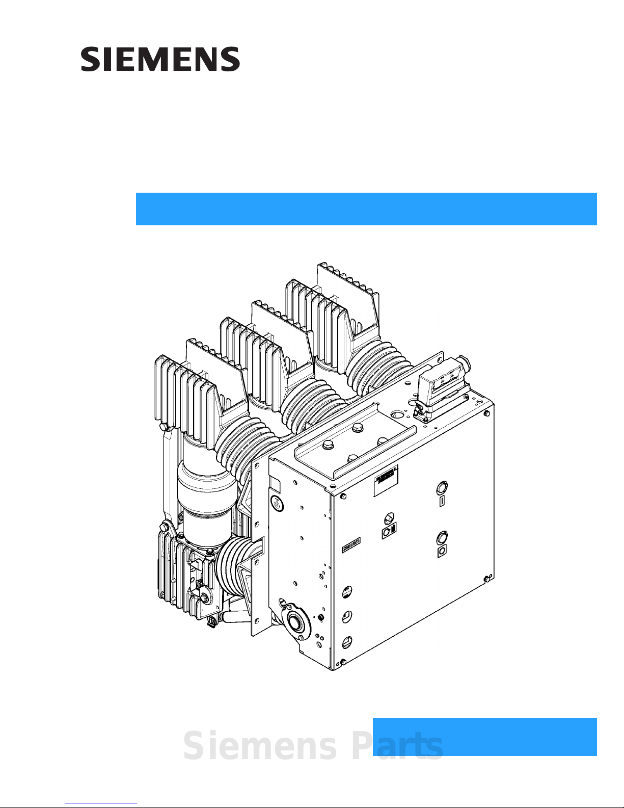
3AH3
Vacuum circuit-breaker
3AH30 ... 3AH33
OPERATING INSTRUCTIONS
Order no.: 9229 9860 176 0E
Ordering location: IC LMV LP PO P C41
AG 08.2013 en
Siemens Parts
2 9229 9860 176 0E
2013-08-22
For your safety
Signal terms and defini-
tions
Hazards are classified in accordance with ISO 3864-2 using the following keywords:
• DANGER, WARNING or CAUTION, where there is a risk of personal injury
• NOTE, where there is a risk of material damage.
Hazards are classified and indicated in the operating instructions and on the vacuum
circuit-breaker as follows:
Qualified personnel are, for the purposes of this manual or the warning notices on the vacuum circuit-
breaker, persons who are familiar with the transport, storage, placement, assembly,
commissioning, operation and maintenance of the product and have the qualifications corresponding to their activity, such as:
• training and authorization to energise, de-energise, clear, earth and tag circuits
and equipment in accordance with established safety practices.
• training in the proper care and use of protective equipment in accordance with
established safety practices;
• training in providing first aid.
Product liability
DANGER
signal word used to indicate an imminently hazardous situation which,
if not avoided, will result in death or serious injury.
WARNING
signal word used to indicate a potentially hazardous situation which,
if not avoided, could result in death or serious injury.
CAUTION
signal word used to indicate a potentially hazardous situation which,
if not avoided, could result in minor or moderate injury.
Note
indicates a potentially damaging situation.
If the damaging situation is not avoided, the product or something in its vicinity
may sustain damage.
Note
Product liability claims are upheld only if the replacement of the purchased spare
parts is performed by personnel that have been trained and certified by Siemens.

9229 9860 176 0E 3
2013-08-22
Table of contents
For your safety .................................. ................................................................ ................................................. 2
Transport, storage and packing .............................. ............. ............. ............. ............. ............ ............. ....... 5
Transport ................................ ................ ................ ................ ................. ................ ..............................................5
Unpacking (I) .........................................................................................................................................................6
Unpacking (II) ..................................................................................................................................................... 10
Unpacking (III) .................................................................................................................................................... 12
Reusing the transport unit .................................................................................................................................. 15
Storage ...............................................................................................................................................................15
General information ....................................................................................................................................... 17
Range of application ...........................................................................................................................................17
Standards ..................................... ................. ................ ................ ................ ..................................................... 18
Design approval as per X-Ray Ordinance ..........................................................................................................18
Scope of delivery ................................................................................................................................................18
Description ........................................................................................................................................................ 19
Design ....................................... ................................................. .........................................................................19
Locking devices ................................................................................................................................................. 32
Rating plate ...................................... .......................................... ... ... .................................................................. 35
Technical data .....................................................................................................................................................35
Ambient conditions ............................................................................................................................................. 36
Installation altitudes ............................................................................................................................................36
Switching times .................................................................................................................................................. 37
Circuit diagrams ................................................................................................................................................. 38
Mounting ....................................... .......................... ............................. ............................. .................................. 43
Attachment in the switching cubicle .............................................................. ... ... .... ... .........................................43
Earthing ..................................... .................... ................... ................... .................... ........................................... 45
Electrical connection of the prime conductor ................................................................... .... ... ........................... 47
Operation .......................................... ................................ ............................. ..................................................... 49
Commissioning ...................................................................................................................................................49
First closing operation .........................................................................................................................................50
Closing ................................................................................ ................................................................................51
Opening ..............................................................................................................................................................51
Maintenance .................................... ................................................................... ............................................... 53
Maintenance and servicing .................................................................................................................................53
Interrupter service life ..... .... ... ... ... .... .......................................... ... ... .................................................................. 56
Accessories and spare parts ...............................................................................................................................56
Manufacturer's product liability ........................................................................................................................... 57
Disposal ..............................................................................................................................................................57
Service ................................... ............................................................................. ................................................57
Index of keywords .......................................................................................................................................... 59
Legend for all pages ...................................................................................................................................... 61
Note
Sections with Addendum (I), (II) or (III)
Sections with Addendum (I) refer to vacuum circuit-breakers with a rated operating current of < 3150 A. Sections
with Addendum (II) refer to vacuum circuit-breakers packed with brackets with vertical connecting bars and a rated
operating current of ≤ 4000 A. Sections with Addendum (III) refer to vacuum circuit-breakers with a rated operating
current of 3150 A.
If no addendum is given, the information is applicable for all 3AH3 vacuum circuit-breakers.
Siemens Parts

4 9229 9860 176 0E
2013-08-22
Blank page
Transport, storage and packing
9229 9860 176 0E 5
2013-08-22
Transport, storage and packing
Transport
Transport weight Refer to the delivery slip for the weight of the transport unit.
Place the transport unit on a level, non-slip and pressure-resistant surface for intermediate storage.
Transport vacuum circuit-breaker in the original transport unit up to the installation
site or storage location.
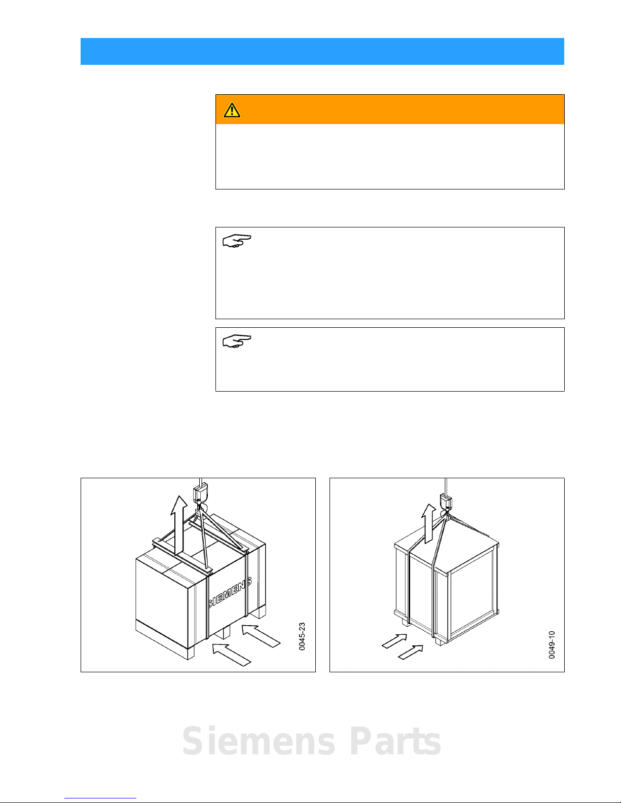
Transporting with crane or fork lift
WARNING
Heavy transport weight
Transport unit may fall and fail and sling gear may break.
Use lifting gear, transporting and sling gear suited to the requirements and load-
carrying capacity. Observe transport symbols.
Note
Observe stacking height
For transport, no more than three constructionally identical transport units must
be piled on top of each other.
Observe the loads specified on the transport unit.
Note
Secure load
For transport, secure the load in such a way that the transport unit is not at risk.
Fig. 1 Transporting the pallet with carton (I) Fig. 2 Transporting the wooden case (III)
Siemens Parts
Transport, storage and packing
6 9229 9860 176 0E
2013-08-22
Transporting with packing Transport the transport unit to the installation site or storage location
• with a fork lift or
• with sling gear suspended from a crane
- at an angle of twist of approx. 60° or
- with a spreader bar.
After receipt of delivery:
Checking the transport
unit
• Check transport unit for damage.
• Major damage must be documented photographically.
• Ensure that any damage to the transport unit is confirmed by the transport company.
Unpacking (I)
Working equipment Required tools:
- Knife/scissors
- Lifting equipment with lifting gear
- Pliers or lever.
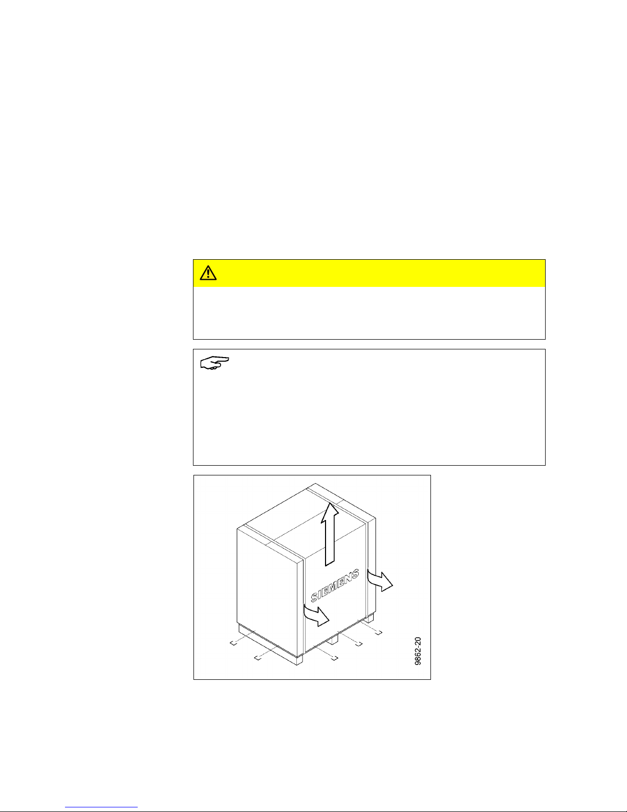
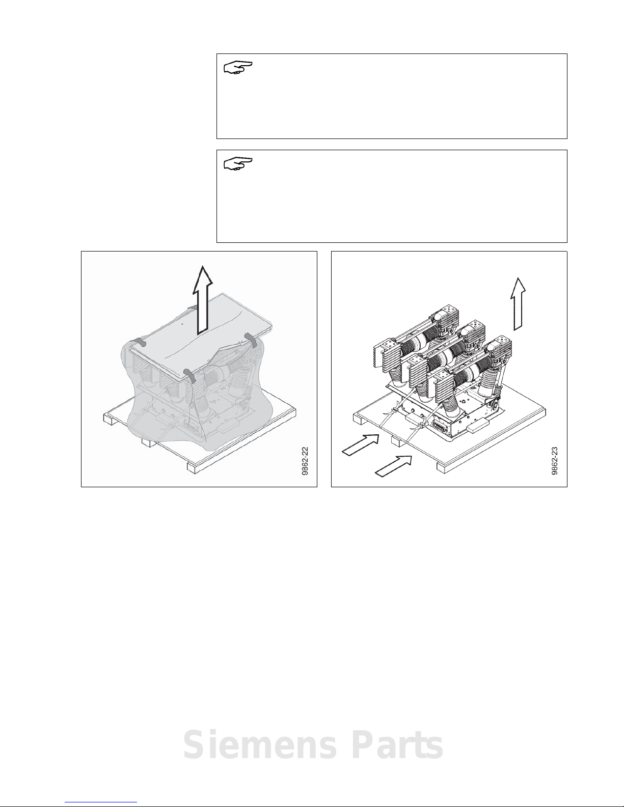
Opening the transport unit • Place the transport unit on a level, non-slip and pressure-resistant surface.
• Remove lifting gear or transport means.
• Remove plastic wrap.
• Lever out fasteners from the carton and lift off carton.
CAUTION
Risk of injury from sharp edges!
Fasteners may break, leaving sharp edges.
Always use a suitable tool to lever out fasteners.
Note
Do not cut open or damage the carton, since it is designed t o be reused and
because of the belt straps located underneath.
Belt straps could be severed on the pallet floor when cutting open the carton.
The vacuum circuit-breaker is attached to the pallet with belt straps. It is not pos-
sible to transport the vacuum circuit-breaker on the pallet without using belt strap s
(see Fig. 5).
Fig. 3 Removing the carton
Transport, storage and packing
9229 9860 176 0E 7
2013-08-22
• Remove partitions and accessory pack and store safely in the packaging for
later attachment.
• Remove film from the vacuum circuit-breaker.
• In the case of overseas packaging, push the lower film onto the pallet floor.
• Check the delivery is complete.
• Check vacuum circuit-breaker for damage.
• If the vacuum circuit-breaker is damaged, ship it back in the original transport
unit (see “Reusing the transport unit”, page 15).
Transporting with pallet,
without carton
The vacuum circuit-breaker can be transported with the pallet, without the carton.
• Thread carrying straps under the pallet or
• transport with fork lift.
Note
Do not use the vacuum circuit-breaker if parts are broken, i.e. if you find cracks,
flaking, bent metal parts, damaged plug-in contacts, tears or bare cables.
Send it back in its original transport unit (see “Reusing the transport unit”,
page 15).
Note
Carrying straps may scrape along the vacuum circuit-breaker and damage it.
If necessary, cover carrying straps with edge protection.
Select length and position of the carrying straps so that the pole heads are not
compressed.
Fig. 4 Removing partitions and film Fig. 5 Transporting with pallet possible
Siemens Parts
Transport, storage and packing
8 9229 9860 176 0E
2013-08-22
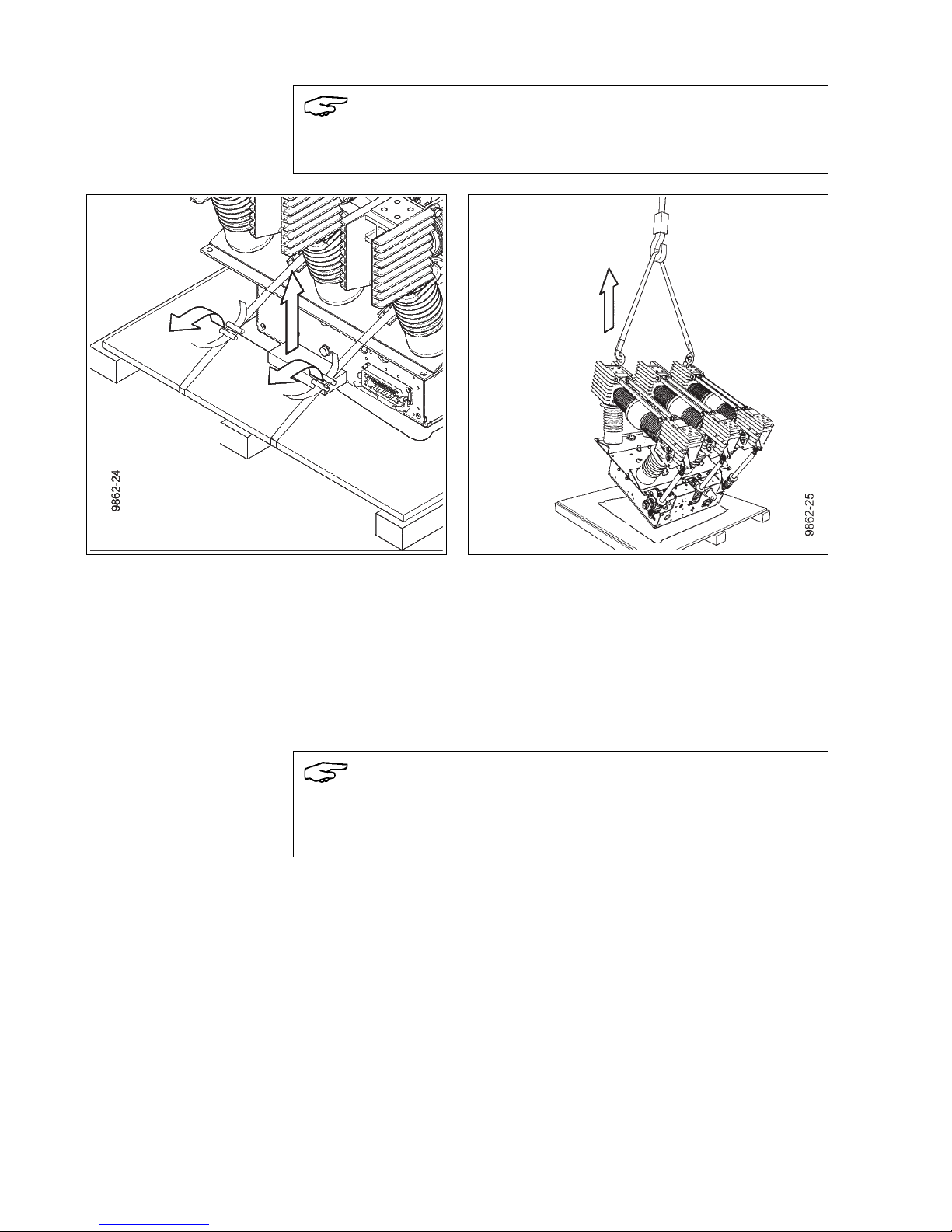
Transporting without pallet • Remove all tensioning belts and bits of fastening wood.
• Remove accessory pack, if applicable.
• Screw suitable eyebolts into the outer pole heads parallel to each other.
• Hang sling gear into the eyebolts.
• Carefully lift vacuum circuit-breaker off the pallet just enough that pieces of
square timber can be placed underneath.
Note
When fastening the eyebolts to the pole heads, ensure that the contact surfaces
are not damaged.
Fig. 6 Removing the tensioning belts Fig. 7 Screwing in eyebolts and lifting the vacuum
circuit-breaker
Note
Place pieces of square timber onto the pallet in such a way that the insulating
operating rods, contact pressure springs, angle levers and dashp ots are not damaged when setting down.
Transport, storage and packing
9229 9860 176 0E 9
2013-08-22
• Set the vacuum circuit-breaker down onto the square timbers.
• Hang further sling gear into the transport boreholes.
• Transport to installation site or leave suspended from crane for further work
steps.
Fig. 8 Positioning the square timbers and setting
down the vacuum circuit-breaker
Fig. 9 Transporting without pallet
Siemens Parts
Transport, storage and packing
10 9229 9860 176 0E
2013-08-22
Unpacking (II)
Variant with brackets
Remove carton as described in Fig. 1 and Fig. 3.
Working equipment Required tools:
- Knife/scissors
- Screwdriver
- Open-end wrench
- Lifting equipment with lifting gear.
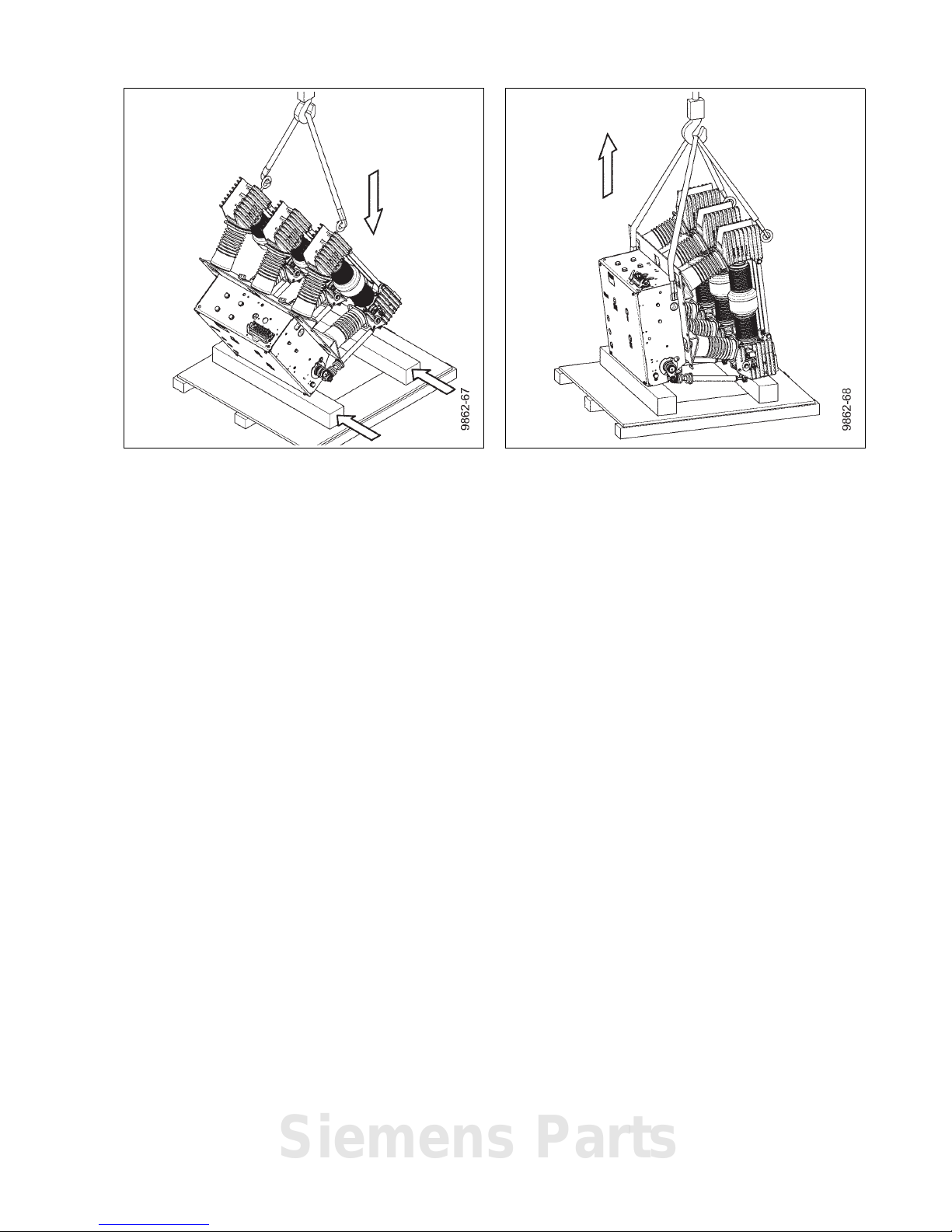
Transporting with brackets • Remove partitions and accessory pack and store safely in the packaging for
later attachment.
• Attach suitable bolt in the middle pole head.
• Attach sling gear to bolt and to transport boreholes.
Fig. 10 Removing partitions and film Fig. 11 Lifting the vacuum circuit-breaker
Transport, storage and packing
9229 9860 176 0E 11
2013-08-22
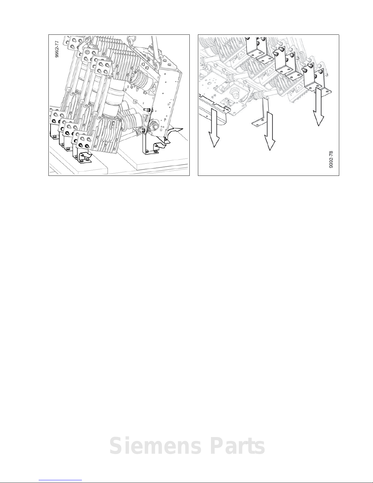
Transporting without
brackets
• Only lift the vacuum circuit-breaker far enough to put all sling gear under tension.
• Remove angle plate and bracket screws from the pallet.
• Lift the vacuum circuit-breaker from the pallet.
• Remove all screw connections from the brackets on the pole plate and the terminals.
• Remove angle plate below mechanism box.
• Transport to installation site or leave suspended from crane for further work
steps.
Fig. 12 Removing screws from the pallet Fig. 13 Removing the angle plate and brackets
Siemens Parts
Transport, storage and packing
12 9229 9860 176 0E
2013-08-22
Unpacking (III)
Working equipment Required tools:
- Screwdriver
- Knife/scissors
- Lifting equipment with lifting gear.
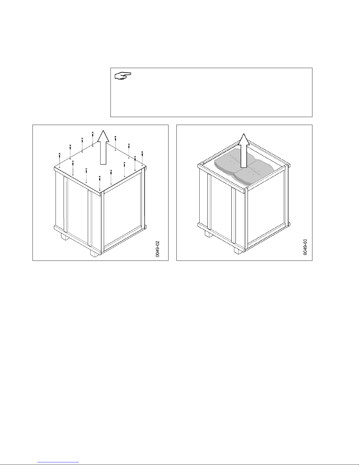
Opening the transport unit • Place the transport unit on a level, non-slip and pressure-resistant surface.
• Remove lifting gear or transport means.
• Unscrew all the screws from the cover and lift it off.
• Remove partitions and store safely in the packaging for later attachment.
Note
Do not use the vacuum circuit-breaker if parts are broken, i.e. if you find cracks,
flaking, bent metal parts, damaged plug-in contacts, tears or bare cables.
Send it back in its original transport unit (see “Reusing the transport unit”,
page 15).
Fig. 14 Removing the cover Fig. 15 Taking out the partitions
Transport, storage and packing
9229 9860 176 0E 13
2013-08-22
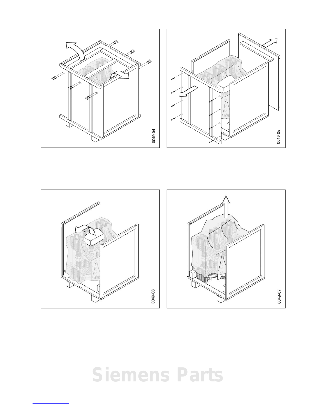
• Unscrew all the screws from the side walls.
• Take the supports out of the transport unit.
• Remove the side walls.
• Remove accessory pack and store safely in the packaging for late r attachment.
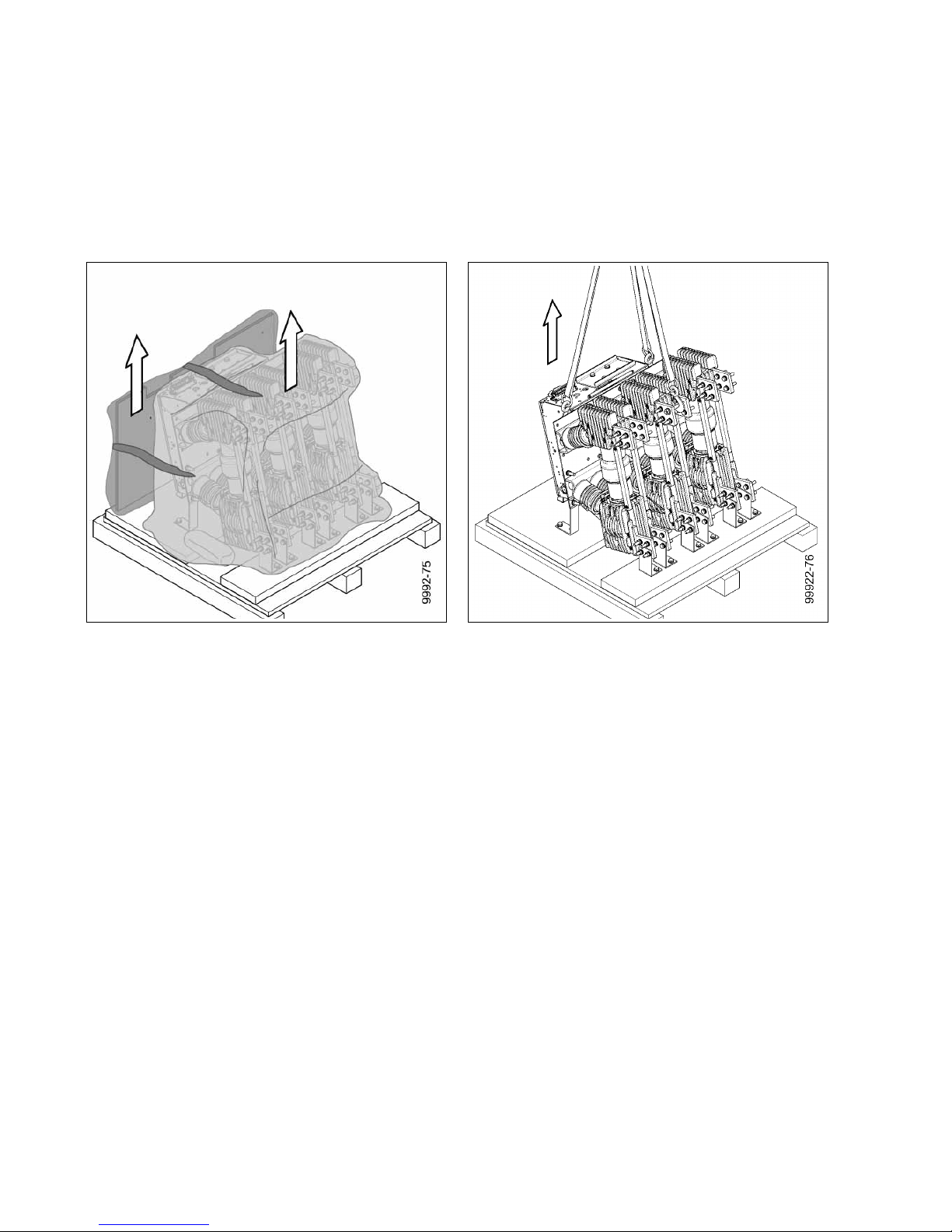
• Remove film from the vacuum circuit-breaker.
• Check the vacuum circuit-breaker for damage.
• Undo tensioning belts, if applicable.
Fig. 16 Removing the supports Fig. 17 Removing the side walls
Fig. 18 Taking out the accessory pack Fig. 19 Removing the film
Siemens Parts

Transport, storage and packing
14 9229 9860 176 0E
2013-08-22
Transporting to the instal-
lation site
• Hook crane hooks into the transport screws and into the openings on the mechanism box.
• Observe crane hook symbols.
• Vertically lift out vacuum circuit-breaker.
• Transport to installation site or leave suspended from crane for further work
steps.
CAUTION
Crushing hazard
Hands may get crushed when lifting out the vacuum circuit-breaker.
Do not reach between the transport box and the vacuum circuit-breaker.
Fig. 20 Preparing for lifting out Fig. 21 Lifting out
Note
Keep partitions and accessory pack ready for the installation.
Transport, storage and packing
9229 9860 176 0E 15
2013-08-22
Reusing the transport unit
Reusing the transport unit To transport the vacuum circuit-breaker again, the pallet with carton or the wooden
case with the most components can be reused.
Do not reuse severed tensioning belts or plastic wrap.
Pack the vacuum circuit-breaker in reverse order:
• Attach the vacuum circuit-breaker safely to the pallet using the appropriate
tools.
• Cover with film and seal with adhesive tape.
• Attach accessories pack.
• Attach carton securely to the pallet floor.
• Screw the wooden case back together.
• Before returning to the factory, ask the responsible sales representative for a
returned goods number (see also “Service”, on page 57).
• When returning a vacuum circuit-breaker, always indicate the type and serial
number (see “Rating plate”, on page 35).
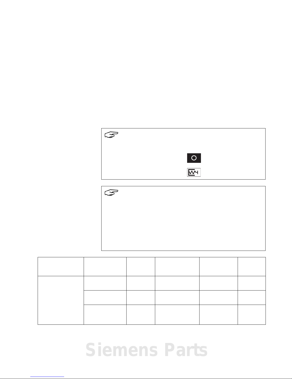
Storage
Note
Store the vacuum circuit-breaker in the following condition:
• OPEN switching position
• Closing spring discharged
Note
Risk of corrosion damage if stored improperly!
If the storage conditions listed below are met, the vacuum circuit-breaker can be
stored for up to a year in its transport unit.
If the storage conditions are not met, the vacuum circuit-breaker ca nnot be stored
in the transport unit any longer than 6 months.
If storage of longer than one year is planned, unpack the vacuum circuit-breaker
from the transport unit. Further storage may necessitate fresh corrosion protection, and it must be ensured that the vacuum circuit-breaker cannot be damaged.
Storage room Transport unit Storage
time
Temperature
range
Comments Number of
units per
stack
Enclosed, dry, well
ventilated and as
free from dust as
possible, with a relative humidity of less
than 60 %.
unopened
max.
6months
-40°C to +55°C — max. 4
unopened
max.
1 year
-5 °C to +40 °C — max. 4
open over 1 year -5 °C to +40 °C
if necessary,
with new corrosion protection
—
Siemens Parts

Transport, storage and packing
16 9229 9860 176 0E
2013-08-22
Blank page
General information
9229 9860 176 0E 17
2013-08-22
General information
Smooth and safe operation of this device requires proper transport and storage, a nd
professional installation and assembly, as well as careful operation and maintenance.
The basic version and all listed configurations of the vacuum circuit-breakers are
type-tested devices as per IEC.
Range of application
3AH3 vacuum circuit-breakers are 3-pole interior circuit-breakers for a rated voltage
range of 7.2 kV - 36 kV.
Under normal operating conditions, the vacuum circuit-breaker (as per IEC 62271-1
and VDE 0671-1) is maintenance-free up to 10 000 operating cycles.
Intended use 3AH3 vacuum circuit-breakers are suitable for switching any type of alternating cur-
rent circuits under normal operating conditions, such as:
• Three-phase motors for reversing, turning and direct operation
• Transformers
• Capacitors
• Resistor consumers
Suitable for high frequency of operation and unlimited on-time.
3AH3 vacuum circuit-breakers operate in continuous, periodic and short-term oper-
ation.
WARNING
Dangerous voltage and mechanical movements
When operating electrical devices, certain parts will always be live, and
mechanical parts may move very quickly, even when remotely controlled.
If the warnings are not observed, serious injury or damage to material may be the
result.
Only personnel with the relevant qualifications may work on or in the vicinity of
this device. These personnel must be familiar with all the warnings and servicing
measures specified in these operating instructions.
Note
In the event of subsequent attachments or integrations, e. g. locking parts in connection with switchgears, ensure that
• fast-moving parts are not additionally loaded with mass or force, and
• additional parts have sufficient clearance, especially from moving and live
parts.
If vacuum circuit-breakers are to be equipped with additional functions by the customer, we recommend consulting the factory, since tried and tested solutions are
frequently available (see also “Additional equipment” on page 23).
Siemens Parts

General information
18 9229 9860 176 0E
2013-08-22
Standards
The 3AH3 vacuum circuit-breakers comply with the regulations:
• IEC 62271-1 and
• IEC 62271-100
All 3AH3 vacuum circuit-breakers comply with the specifications for C2-, E2- and
M2-class circuit-breakers in accordance with IEC 62271-100.
Design approval as per X-Ray Ordinance
The vacuum interrupters installed in th e vacuum circuit-breakers are of a design
approved under the X-Ray Ordinance (RöV) of the Federal Republic of Germany.
They meet the requirements of RöV of 8 January 1987 (BGbl. I, page 114) § 8 and
Annex II No. 5 up to the level of the rated voltage stipulated according to DIN
VDE/IEC.
Scope of delivery
Delivery includes:
• Vacuum circuit-breaker 3AH3
• Hand crank for circuit-breaker 3AX 1530-2B (optional)
• If applicable, partitions with mounting drawing
• Operating instructions and unpacking instructions
• Circuit-breaker-specific circuit diagrams
Description
9229 9860 176 0E 19
2013-08-22
Description
Design
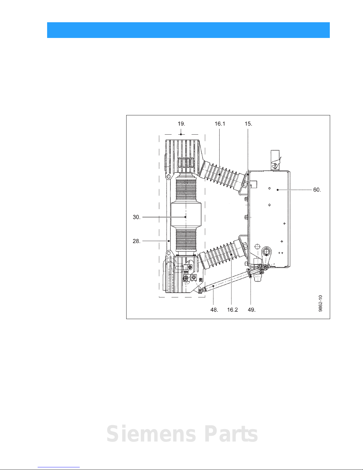
Vacuum circuit-breaker The 3AH3 vacuum circuit-breaker consists of
• the mechanism box (60.),
• the 3 pole assemblies (19.) with vacuum interrupters (30.),
• the cast resin post insulators (16.1 and 16.2) with reinforcing struts (28.) and
• the insulating operating rods (48.) with contact pressure springs (49.) required
for contact actuation.
Each of the 3 pole assemblies (19.) is carried by the cast resin post insulators (16.1
and 16.2) that are screwed to the pole plate (15.).
Fig. 22 Side view
15. Pole plate
16.1 Upper post insulator
16.2 Lower post insulator
19. Pole assembly, complete
28. Strut
30. Interrupter
48. Insulating operating rods
49. Contact pressure spring
60. Mechanism box
Siemens Parts
Description
20 9229 9860 176 0E
2013-08-22
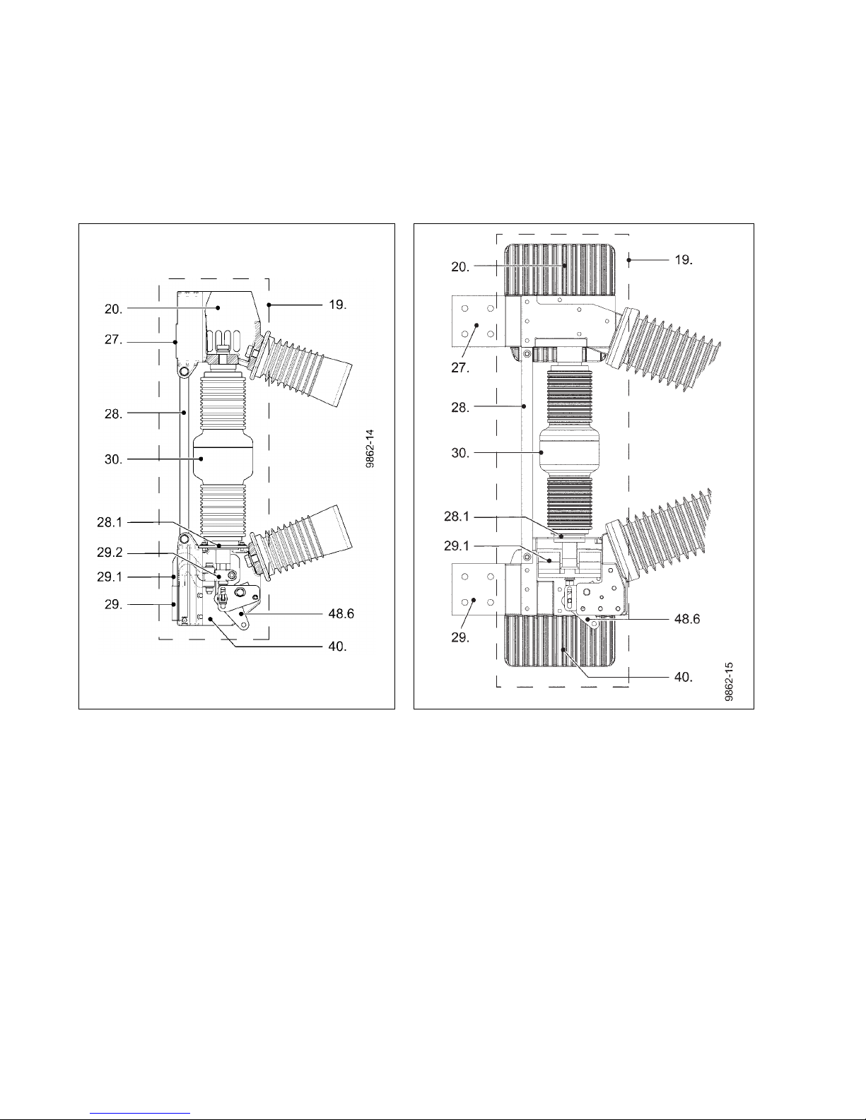
Pole assembly The pole assembly (19.) of the 3AH3 vacuum circuit-breaker consists of
• the upper interrupter support (20.)
• with the upper terminal (27.)
• the vacuum interrupter (30.),
• the lower interrupter support (40.) with the lower terminal (29.) and the clamp
(29.2) with flexible connector (29.1);
• as well as the angle lever (48.6.).
The centering (28.1) and the struts (28.) relieve the vacuum interrupters of external
forces.
Contact system in the interrupters
A slight change in the contact stroke that occurs over the entire useful life of the
interrupter has no effect on the function of the vacuum circuit-breaker. There is no
need for a status indicator for the contact system.
Fig. 23 Pole assembly (I) Fig. 24 Pole assembly (II and III)
19. Pole a ssembly 29.1 Flexible connector
20. Upper inter rupter support 29.2 Clamp
27. Upper terminal 30. Interrupter
28. Strut 40. Lower interrupter support
28.1 Centering 48.6 Angle lever
29. Lower terminal
 Loading...