

Page 1

Wonderware Siemens 3964R
I/O Server
User’s Guide
Revision S
June 2002
Wonderware
Page 2

All rights reserved. No part of this documentation shall be reproduced, stored in a
retrieval system, or transmitted by any means, electronic, mechanical, photocopying,
recording, or otherwise, without the prior written permission of the Invensys Systems,
Inc. No copyright or patent liability is assumed with respect to the use of the information
contained herein. Although every precaution has been taken in the preparation of this
documentation, the publisher and the author assume no responsibility for errors or
omissions. Neither is any liability assumed for damages resulting from the use of the
information contained herein.
The information in this documentation is subject to change without notice and does not
represent a commitment on the part of Invensys Systems, Inc. The software described in
this documentation is furnished under a license or nondisclosure agreement. This
software may be used or copied only in accordance with the terms of these agreements.
2002 Invensys Systems Inc. All Rights Reserved.
Invensys Systems, Inc.
33 Commercial Street
Foxboro, MA 02035
(949) 727-3200
http://www.wonderware.com
Trademarks
All terms mentioned in this book that are known to be trademarks or service marks have
been appropriately capitalized. Invensys Systems, Inc. cannot attest to the accuracy of
this information. Use of a term in this book should not be regarded as affecting the
validity of any trademark or service mark.
Alarm Logger, ActiveFactory, ArchestrA, Avantis, DBDump, DBLoad, DTAnalyst,
FactoryFocus, FactoryOffice, FactorySuite, hotlinks, InBatch, InControl, IndustrialRAD,
IndustrialSQL Server, InTouch, InTrack, MaintenanceSuite, MuniSuite, QI Analyst,
SCADAlarm, SCADASuite, SuiteLink, SuiteVoyager, WindowMaker, WindowViewer,
Wonderware, and Wonderware Logger are trademarks of Invensys plc, its subsidiaries
and affiliates. All other brands may be trademarks of their respective owners.
Page 3

i
Contents
Introduction .............................................................................................................................1
Communication Protocols ...................................................................................................1
Accessing Remote Items via the I/O Server............................................................................2
Configuring the I/O Server......................................................................................................3
Configuring a Communication Port ........................................................................................4
Communication Port Settings..............................................................................................4
Saving the I/O Server’s Configuration File.............................................................................6
Save Configuration..............................................................................................................6
Saving Multiple Configuration Files ...................................................................................6
Configuring a Topic Definition ...............................................................................................7
Topic Definition ..................................................................................................................7
S3964R Topic Definition ....................................................................................................8
Configuring the I/O Server Settings ......................................................................................10
Server Settings................................................................................................................... 10
Accessing I/O Server Help .................................................................................................... 12
Contents.............................................................................................................................12
How to Use Help ............................................................................................................... 12
About S3964R ...................................................................................................................12
Item Names (S5 Item Syntax)................................................................................................13
Data Blocks/Extended Range Data Blocks....................................................................13
Flags ..............................................................................................................................14
Inputs .............................................................................................................................14
Outputs ..........................................................................................................................15
System Data Area ..........................................................................................................15
Absolute Address...........................................................................................................16
Timers............................................................................................................................ 16
Counters.........................................................................................................................16
Item/Point Naming Examples............................................................................................17
Item Names (S7 Item Syntax)................................................................................................18
Data Blocks ...................................................................................................................18
Flags ..............................................................................................................................19
Inputs .............................................................................................................................20
Outputs ..........................................................................................................................21
Timers............................................................................................................................ 21
Counters.........................................................................................................................21
Item/Point Naming Examples............................................................................................22
Monitoring the Status of Communications with a PLC.........................................................23
Page 4

ii
Using the Status Item in Excel.......................................................................................... 23
Monitoring the Status of Communications with InTouch..................................................... 23
Using DDEStatus and IOStatus in Excel .......................................................................... 23
Reading Values from the I/O Server into Excel.................................................................... 24
Writing Values to the I/O Server from Excel ....................................................................... 25
Troubleshooting I/O Server Communication Problems........................................................ 26
Debugging Communication Between InTouch and an I/O Server ................................... 26
Debugging Communication Between SuiteLink and an I/O Server ................................. 28
Debugging Communication Between an I/O Server and a PLC....................................... 29
Special Wonderware Logger Messages ................................................................................ 36
Siemens REPTEL Errors .............................................................................................. 36
Page 5

1
Wonderware Siemens
3964R I/O Server
Introduction
The Wonderware
remainder of this user’s guide) is a Microsoft
as a communication protocol server. It allows other Windows application programs
access to data within the SIMATIC S5 and S7 family of PLCs (also referred to as
devices). The server allows the PC to access a Siemens PLC through a CPU or CP
which supports the 3964R protocol with RK512. While the server is primarily intended
for use with Wonderware InTouch
Microsoft Windows program capable of acting as a DDE, FastDDE, or SuiteLink
client.
Communication Protocols
Siemens 3964R I/O Server (referred to as the server through the
(version 3.01 or later), it may be used by any
Windows application program that acts
Dynamic Data Exchange (DDE) is a communication protocol developed by Microsoft
to allow applications in the Windows environment to send/receive data and instructions
to/from each other. It implements a client-server relationship between two concurrently
running applications. The server application provides the data and accepts requests
from any other application interested in its data. Requesting applications are called
clients. Some applications such as InTouch and Microsoft Excel can simultaneously be
both a client and a server.
FastDDE provides a means of packing many proprietary Wonderware DDE messages
into a single Microsoft DDE message. This packing improves efficiency and
performance by reducing the total number of DDE transactions required between a
client and a server. Although Wonderware's FastDDE has extended the usefulness of
DDE for our industry, this extension is being pushed to its performance constraints in
distributed environments.
NetDDE
over local area networks and through serial ports. Network extensions are available to
allow DDE links between applications running on different computers connected via
networks or modems. For example, NetDDE supports DDE between applications
running on IBM
applications running on non-PC based platforms under operating environments such as
VMS
extends the standard Windows DDE functionality to include communication
compatible computers connected via LAN or modem and DDE-aware
and UNIX.
Page 6

2
SuiteLink uses a TCP/IP based protocol and is designed specifically to meet industrial
needs such as data integrity, high-throughput, and improved diagnostics. This protocol
standard is only supported on Microsoft Windows NT 4.0 and Windows 2000.
SuiteLink is not a replacement for DDE, FastDDE, or NetDDE. The protocol used
between a client and a server depends on your network connections and configurations.
SuiteLink was designed to be the industrial data network distribution standard and
provides the following features:
• Value Time Quality (VTQ) places a time stamp and quality indicator on all data
values delivered to VTQ-aware clients.
• Extensive diagnostics of the data throughput, server loading, computer resource
consumption, and network transport are made accessible through the Microsoft
Windows NT and Windows 2000 operating systems Performance Monitor. This
feature is critical for the scheme and maintenance of distributed industrial
networks.
• Consistent high data volumes can be maintained between applications regardless if
the applications are on a single node or distributed over a large node count.
• The network transport protocol is TCP/IP using Microsoft’s standard WinSock
interface.
Accessing Remote Items via the I/O Server
The communication protocol addresses an element of data in a conversation that uses a
three-part naming convention that includes the application name, topic name and item
name. The following briefly describes each portion of this naming convention:
application name The name of the Windows program (server) that will be
accessing the data element. In the case of data coming from
or going to Siemens equipment via this server, the
application portion of the address is S3964R.
topic name Meaningful names are configured in the server to identify
specific devices. These names are then used as the topic
name in all conversations to that device. For example,
S115U.
Note You can define multiple topic names for the same
device (PLC) to poll different points at different rates.
item name A specific data element within the specified topic. For
example, when using this server, an item can be a relay,
timer, counter, register, etc., in the PLC.
Note The item/point names are predefined by the server.
The term "point" is used interchangeably with the term
"item" in this user's guide.
For more information on item/point names, see the
“Item Names" section later in this user's guide.
Page 7
3
Configuring the I/O Server
Once the server has been installed, a small amount of configuration is required.
Configuring the server automatically creates a configuration file named S3964R.CFG.
This file stores the configuration information for the adapter cards or communication
ports and all of the topic definitions (described in detail later).
The configuration file is automatically saved to the directory in which the server is
installed unless a different directory is specified.
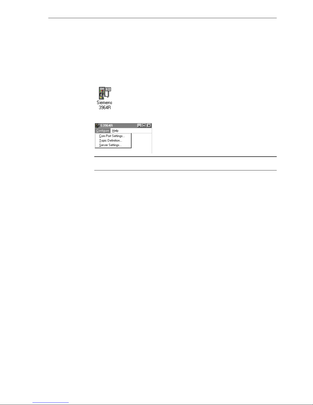
To perform the required configurations, start up the server
by double-clicking on its icon. If the server starts up as an
icon, double-click on the icon to open the server's window.
To access the options used for the various configurations, open the Configure menu:
Note If any of the options appear grayed, then these options are not available with this
software version.
Page 8
4
Configuring a Communication Port
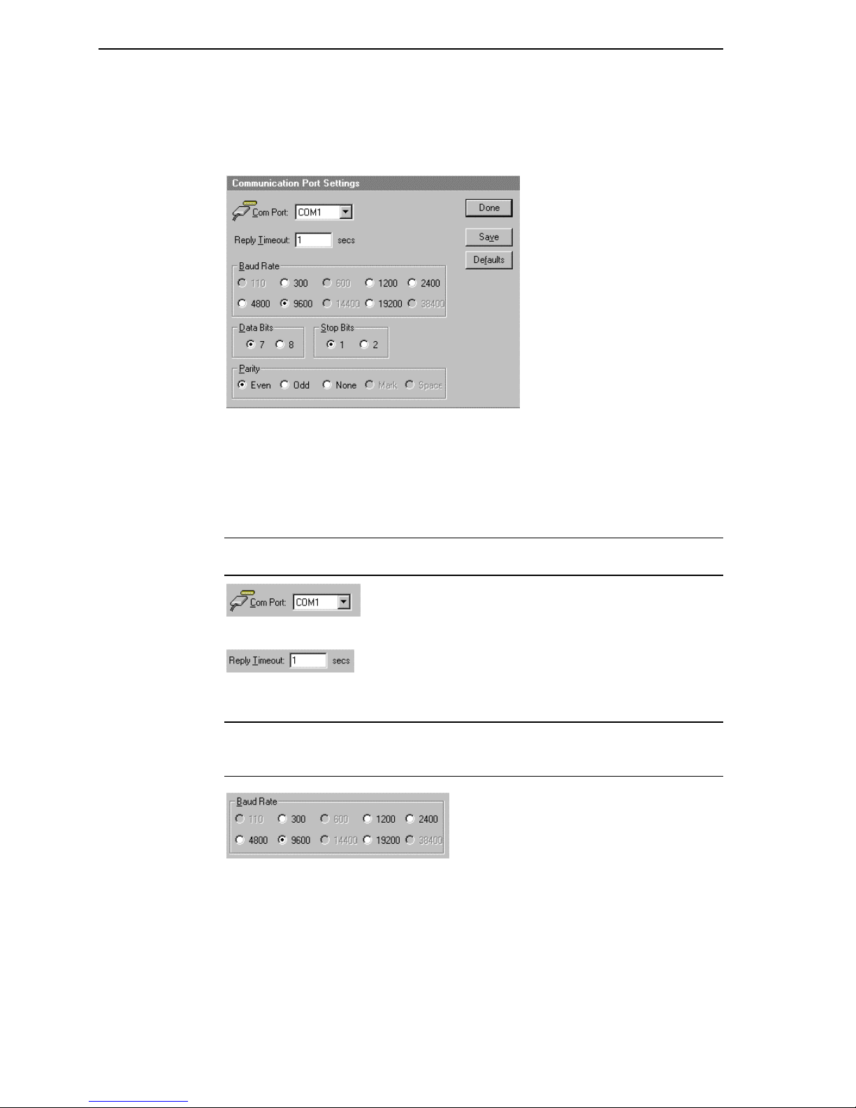
Use the Communication Port Settings option from the Configure Menu to configure
the communication ports that will be used for communication with Siemens devices.
When this option is selected, this dialog box will appear:
Communication Port Settings
Note All communication ports can be configured without leaving this dialog box.
Repeat these steps; select a COM Port, set configuration, and click Save.
Select a communication port connected to the Siemens device.
Enter the amount of time (in seconds) that all PLCs connected via this communication
port will be given to reply to commands from the server.
Note This timeout is sustained only when the PLC fails to respond. When the PLC is
responding normally, there is no penalty. The default value of 1 second should be
sufficient for most configurations.
Select the Baud Rate (serial bit rate) setting that matches the configuration of the
Siemens device.
Page 9
5
Select the number of Data Bits that matches the configuration of the Siemens device.
Select the number of Stop Bits that matches the configuration of the Siemens device. If
the Baud Rate is greater than 300, the Stop Bits should be set to 1.
Select the Parity setting that matches the configuration of the Siemens device.
All devices on a single communication port must be configured with the same Baud
Rate, Data Bits, Stop Bits, and Parity.
Click Defaults to reset the settings to their default values without saving changes.
Click Save to save settings for the selected COM Port. The dialog box will remain
displayed giving you the option to configure additional COM Ports.
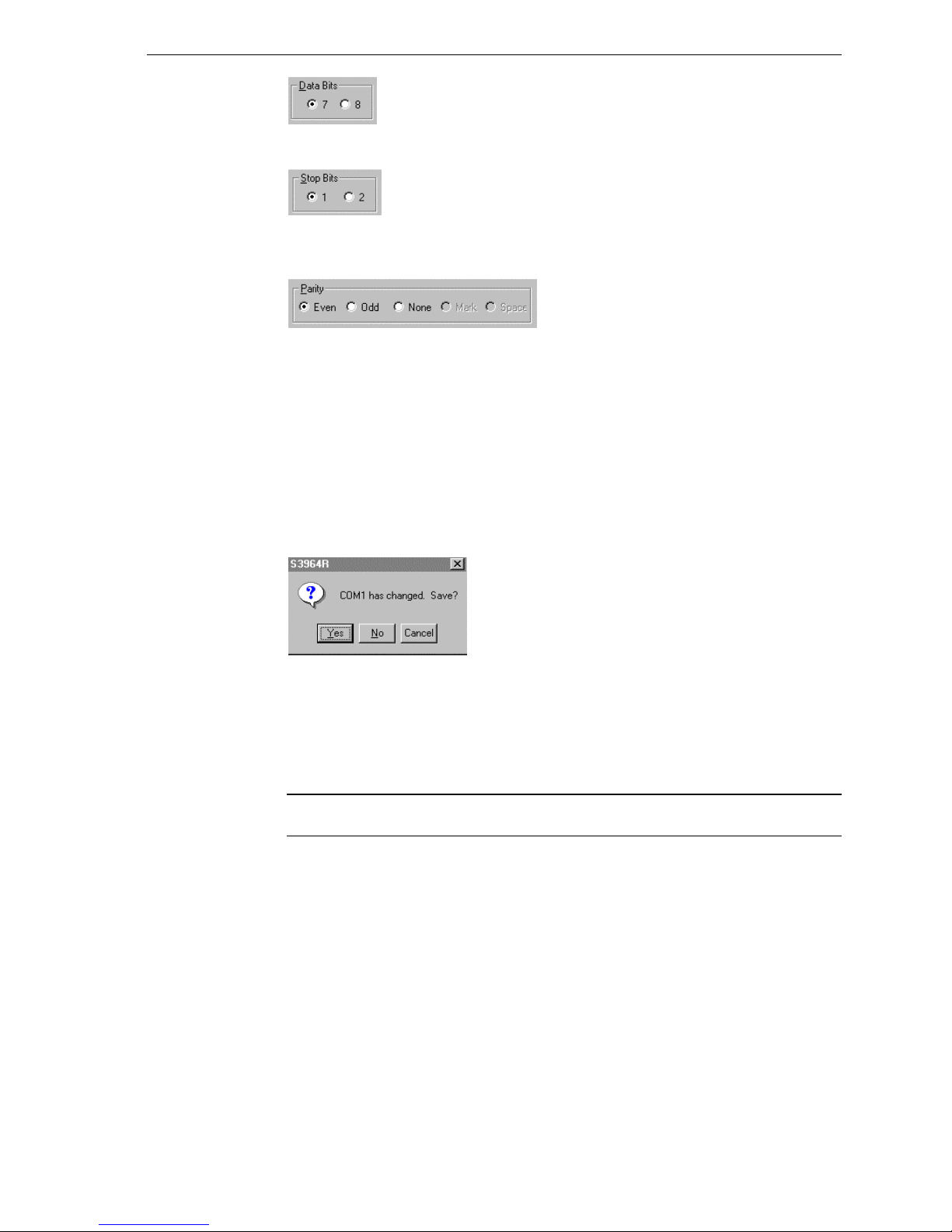
Click Done to close the dialog box. If the settings have not been saved, the following
dialog box will appear:
Click Yes to save settings for the COM Port.
Click No to prevent saving the settings.
Click Cancel to return to the Communication Port Settings dialog box without saving
the settings.
Note For most of these settings only one setting is allowed. All other possibilities are
disabled.
Page 10
6
Saving the I/O Server’s Configuration File
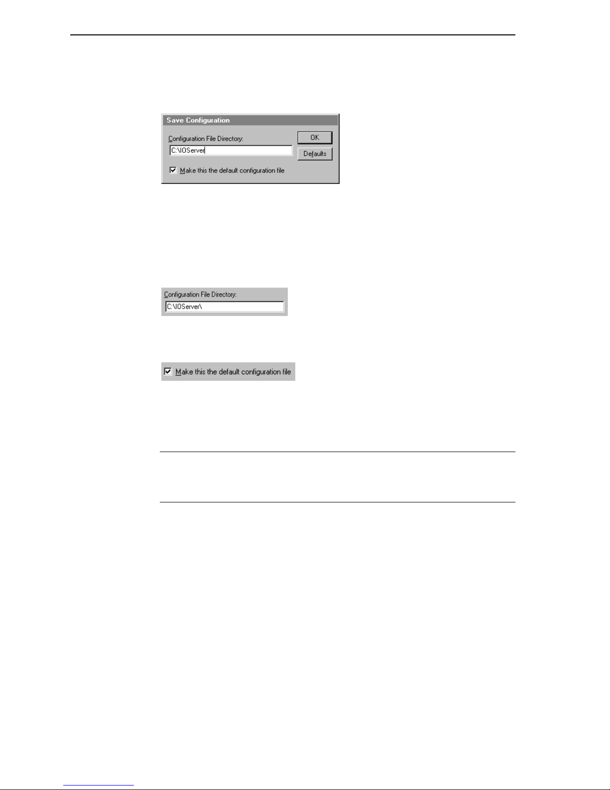
If a configuration file does not currently exist in the configuration file directory, the
server will automatically display the Save Configuration dialog box:
Save Configuration
This field displays the drive\directory into which the server will save the current
configuration file. To save the configuration file to a different directory, enter the path
for that directory in this field.
This option is selected and disabled on initial entry to the Save Configuration dialog
box. This field becomes active if the Configuration File Directory is changed. Once
enabled, selecting this option will record a new Configuration File path in the WIN.INI
file. This option allows the server to find its configuration file automatically each time
it is started.
Note When the server initially starts up, it attempts to locate its default configuration
file by first checking the WIN.INI file for a previously specified path. If a path is not
present in the WIN.INI file, the server will assume that the current working directory is
to be used.
Click Defaults to reset the settings to their default values without saving changes.
Click OK to save the configuration file to the specified directory.
Saving Multiple Configuration Files
There is no limit to the number of configuration files that you can create as long as they
are saved in separate directories. However, all cfg files must have the name
S3964R.CFG. This allows you to have multiple configuration files that can be accessed
by using a special switch (/d:). For example, to start the server using a configuration
file located in a different directory, click the Start button on the Taskbar, then choose
Run and enter the following in the Open combo box:
S3964R /d:c:\directoryname
Page 11
7
Configuring a Topic Definition
Use the Topic Definition option from the Configure menu to create new, modify, or
delete topic definitions. One or more topic definitions must exist for each PLC that the
server will communicate with. Each topic definition must contain a unique name for
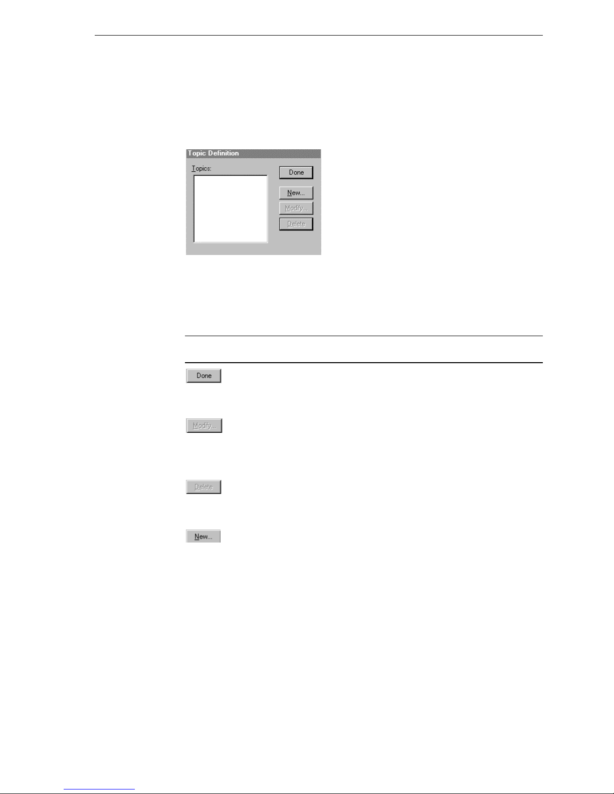
the PLC associated with it. When this option is selected, the Topic Definition dialog
box will appear:
Topic Definition
Note Once topics have been defined, their names will be listed in the Topics section of
this dialog box.
Click this button to close the dialog box and accept any new definitions, modifications
or deletions made.
To modify or view an existing topic definition, select its name in the list and click on
this button. The S3964R Topic Definition dialog box (described below) will appear
displaying the selected topic definition.
To delete an existing topic definition, select its name in the list and click on this button.
(A message box will appear prompting you to confirm the deletion.)
To add a new topic definition, click on this button. The S3964R Topic Definition
dialog box will appear:
Page 12
8
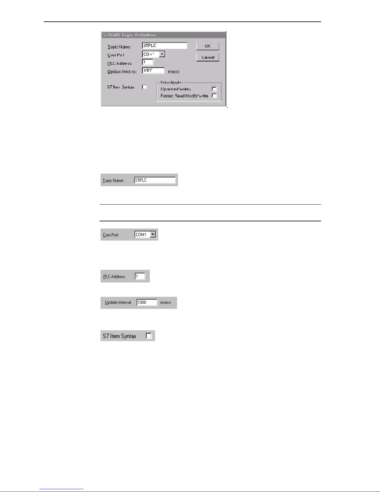
S3964R Topic Definition
Enter a unique name (up to 32-characters long with the first character being alphabetic)
for the PLC in this field.
Note When communicating with InTouch, this exact name is used as the topic name in
the Access Name definition.
The communications port currently associated with this topic will appear in this field.
To select a different port, click on the down arrow to open the list of communication
ports. Click on the name of the communications port to be associated with this topic.
Enter the address on the communications card in the PLC chassis.
Enter the frequency (in milliseconds) that the server will read (poll) the items/points
associated with this topic.
Set the option S7 Item Syntax on if you want to use this syntax insted of S5 Item syntax
(e.g. if connecting to Step 7 PLC’s).
Page 13

9
Set the option Optimized Writes on if you want to increase the speed of poking and
don’t need to retain the poke order.
Set the option Forced Read Modify Write on if you want to have a polling before every
poke of Bits or Bytes. If this option is switched of only the first value will be polled and
combined with the following pokes.
Note Different items/points can be polled at different rates by defining multiple topic
names for the same PLC and setting different update rates for each topic.
Once all the entries have been made, click on the OK button to accept the entries and
close the dialog box. Click on the Cancel button to close the dialog box without saving
changes. The Topic Definition dialog box will reappear:
Click Done to close the dialog box.
Page 14

10
Configuring the I/O Server Settings
Use the Server Settings option from the Configure menu to change the protocol timer,
network using Wonderware NetDDE, change the default configuration file path, or to
enable the server to start automatically as a Windows NT service.
Note When configuring the server on Windows NT, the user must be logged on with
system administrator privileges. This will ensure that updates to the system registry
may be performed.
When the Server Settings option is selected, the Server Settings dialog box will
appear:
Server Settings
Enter the frequency (in milliseconds) that the server is to check for data to process.
This should be approximately two to four times faster than the fastest rate desired to
update data from the equipment.
Note The default protocol timer tick value will vary between servers.
Select this option if you are networking using Wonderware NetDDE.
To create a new default configuration file, enter the complete path for the directory in
which the file is to be saved in this field. This new path will automatically be written to
the WIN.INI file and the server will use this path to load its configuration file the next
time it is started.
Note There is no limit to the number of configuration files created. However, each
must be saved in a different directory. When using the server with InTouch, we
recommend that you save the configuration file in your application directory. For more
information on the Configuration File, see "Saving the I/O Server’s Configuration File"
in this user's guide.
Page 15

11
Enabling this option will cause the server to start as a Windows NT service.
Windows NT offers the capability of running applications even when a user is not
logged on to the system. This is valuable when systems must operate in an unattended
mode. Enabling this option and rebooting the system will cause the server to run as a
Windows NT service. However, to view configuration information or to reconfigure
the server, the user must log on to the system. Any server related problems that may
arise such as missing adapter cards, licensing failures or device drivers not loading will
not be visible to the user until a log on is performed. Disabling this option and
rebooting the system will cause the server to run as a Windows NT application program
once again.
Note It is highly recommended that the server is configured and communicating
successfully prior to running it as a Windows NT service.
Click Cancel to close the dialog box without saving changes.
Click OK to accept the server settings. The following message box will appear:
Click OK to close the dialog box.
Note You must restart the server for the changes to take effect.
Page 16

12
Accessing I/O Server Help
The Help menu contains three options that are used to access help for the server.
The following briefly describes the Help menu options.
Contents
This option is used to display the table of contents for the Help file.
How to Use Help
This option is used to access a list of basic instructions for using the Help file.
About S3964R
This option is used to access miscellaneous information regarding the server, such as
the software version, the copyright information, license information, etc.
Your FactorySuite system license information can be viewed through the license
viewing utility that is launched from the About dialog box.
For more information on the license viewing utility, see your FactorySuite System
Administrator’s Guide.
Page 17

13
Item Names (S5 Item Syntax)
The Siemens 3964R I/O Server supports item/point names that are consistent with the
point naming convention used by Siemens 3964R CPs. The tables below list the
item/point names supported by the server:
Data Blocks/Extended Range Data Blocks
Data Format Items Suffix Tag Type Range
Bit D<B,X>m Dn.b Discrete 0 or 1
String D<B,X>m Sn.z Message 2 to 128
Left Byte D<B,X>m DLn Integer 0 to 255
KF Integer -128 to 127
Right Byte D<B,X>m DRn Integer 0 to 255
KF Integer -128 to 127
Word D<B,X>m DWn Integer 0 to 65535
KF Integer -32768 to 32767
BCD Integer -999 to 999
KC Integer 0 to 999
KT Message 0.0 to 999.3
Double Word D<B,X>m DDk Integer -2147483648 to
2147483647
BCD Integer -9999999 to 9999999
KG Real floating point
Note All data blocks are Read/Write (m=2 to 255, n= 0 to 255, b=0 to 15, k= 0 to 254,
z=length of character string). The string must contain an even number of characters,
e.g., 2, 4, 100, 128, etc.
Page 18

14
Flags
Data
Format
Bit Fm.b Discrete 0 or 1
Mm.b Discrete 0 or 1
Byte FYm Integer 0 to 255
FBm Integer 0 to 255
MBm Integer 0 to 255
KF Integer -128 to 127
Word FWn Integer 0 to 65535
MWn Integer 0 to 65535
KF Integer -32768 to 32767
BCD Integer -999 to 999
KC Integer 0 to 999
KT Message 0.0 to 999.3
Double Word FDk Integer -2147483648 to 2147483647
MDk Integer -2147483648 to 2147483647
BCD Integer -9999999 to 9999999
KG Real floating point
Note All flags are Read Only (m= 0 to 255, n= 0 to 254, b= 0 to 7, k= 0 to 252).
Items Suffix Tag Type Range
Inputs
Data
Format
Bit In.b Discrete 0 or 1
En.b Discrete 0 or 1
Byte IBn Integer 0 to 255
EBn Integer 0 to 255
KF Integer -128 to 127
Word IWm Integer 0 to 65535
EWm Integer 0 to 65535
KF Integer -32768 to 32767
BCD Integer -999 to 999
KC Integer 0 to 999
KT Message 0.0 to 999.3
Double Word IDk Integer -2147483648 to 2147483647
EDk Integer -2147483648 to 2147483647
BCD Integer -9999999 to 9999999
Note All Inputs are Read Only (n= 0 to 127, m= 0 to 126, k= 0 to 124, b= 0 to 7).
Items Suffix Tag Type Range
Page 19

15
Outputs
Data
Format
Bit Qn.b Discrete 0 or 1
An.b Discrete 0 or 1
Byte QBn Integer 0 to 255
Abn Integer 0 to 255
KF Integer -128 to 127
Word QWm Integer 0 to 65535
AWm Integer 0 to 65535
KF Integer -32768 to 32767
BCD Integer -999 to 999
KC Integer 0 to 999
KT Message 0.0 to 999.3
Double Word QDk Integer -2147483648 to 2147483647
ADk Integer -2147483648 to 2147483647
BCD Integer -9999999 to 9999999
Note All Outputs are Read Only (n= 0 to 127, m= 0 to 126, k= 0 to 124, b= 0 to 7).
Items Suffix Tag Type Range
System Data Area
Data
Format
Word RSn Integer 0 to 65535
BSn Integer 0 to 65535
KF Integer -32768 to 32767
BCD Integer -999 to 999
KC Integer 0 to 999
KT Message 0.0 to 999.3
Items Suffix Tag Type Range
Note All System Data Area types are Read Only (n= 0 to 255).
Page 20

16
Absolute Address
Data
Format
Word ASh Integer 0 to 65535
KC Integer 0 to 999
KT Message 0.0 to 999.3
Note All Absolute Addresses are Read Only (h= 0 to FFFF (hex)).
Items Suffix Tag Type Range
Timers
Data
Format
Word Tn Real 0.0 to 9990.0
Note All Timers are Read Only (n= 0 to 255).
Items Suffix Tag Type Range
Counters
Data
Format
Word Cn Integer 0 to 65535
Zn Integer 0 to 65535
Items Suffix Tag Type Range
Note All Counters are Read Only (n= 0 to 255).
Page 21

17
Item/Point Naming Examples
The following examples show the correct format for item/point names:
DB11DW7BCD
data block 11
data word 7
value in controller is represented in BCD and has a range of -999 to 999
DX87DL14KF
extended range data block 87
left byte of data word 14
value in controller is binary and has a range of -128 to 127
DB87DR14
data block 87
right byte of data word 14
value in controller is binary and has a range of 0 to 255
FD17KG or MD17KG
flag double word 17
value in controller is binary floating point
I106.3 or E106.3
bit 3 of input byte 106
FW29KC or MW29KC
flag word 29
value in controller is in counter constant format
DB7DW55KT
data block 7
data word 55
value in controller is in timer constant format
DB5S6.10
data block 5
starting data word 6
10 character strings
T5
timer 5
value in controller is in timer constant format
C20
counter 20
value in controller is in counter constant format
Note Do not enter blank spaces in the item names.
Page 22

18
Item Names (S7 Item Syntax)
The Siemens 3964R I/O Server supports the S7 item/point names that will be translated
internal into S5 item/point names. This means not all S7 items/points can be used by
this server. The tables below list the item/point names supported by the server:
Data Blocks
Data Format Items Suffix Tag
Type
Bit D<B>x,Xm.b Discrete 0 or 1
String D<B>x,Sm,z Message 2 to 128
D<B>x,STRINGm,z Message 2 to 128
Byte D<B>x,Bm Integer 0 to 255
D<B>x,BYTEm Integer 0 to 255
Char D<B>x,CHARm Integer -128 to 127
Word D<B>x,Wn Integer 0 to 65535
D<B>x,WORDn Integer 0 to 65535
KT Message 0.0 to 999.3
Integer D<B>x,INTn Integer -32768 to 32767
BCD Integer -999 to 999
Double Word D<B>x,Dk Integer 0 to 2147483647
D<B>x,DWORDk Integer 0 to 2147483647
Double
Integer
BCD Integer -2147483648 to
Real D<B>x,REALk Real +-3.4e38
Note All data blocks are Read/Write (x=3 to 255, m= 0 to 255, b=0 to 7, n= 0 to 254,
k=252, z=length of character string, n and k must be even). The string must contain an
even number of characters, e.g., 2, 4, 100, 128, etc.
D<B>x,DINTk Integer -2147483648 to
Range
2147483647
2147483647
Page 23

19
Flags
Data
Format
Bit FXm.b Discrete 0 or 1
MXm.b Discrete 0 or 1
Byte FBm Integer 0 to 255
MBm Integer 0 to 255
FBYTEm Integer 0 to 255
MBYTEm Integer 0 to 255
Char FCHARm Integer -128 to 127
MCHARm Integer -128 to 127
Word FWn Integer 0 to 65535
MWn Integer 0 to 65535
FWORDn Integer 0 to 65535
MWORDn Integer 0 to 65535
KT Message 0.0 to 999.3
Integer FINTn Integer -32768 to 32767
MINTn Integer -32768 to 32767
BCD Integer -999 to 999
Double Word FDk Integer 0 to 2147483647
MDk Integer 0 to 2147483647
FDWORDk Integer 0 to 2147483647
MDWORDk Integer 0 to 2147483647
Double
Integer
MDINTk Integer -2147483648 to 2147483647
BCD Integer -9999999 to 9999999
Real FREALk Real +-3.4e38
MREALk Real +-3.4e38
Items Suffix Tag Type Range
FDINTk Integer -2147483648 to 2147483647
Note All flags are Read Only (m= 0 to 255, b= 0 to 7, n= 0 to 254, k= 0 to 252).
Page 24

20
Inputs
Data
Format
Bit Im.b Discrete 0 or 1
Em.b Discrete 0 or 1
IXm.b Discrete 0 or 1
EXm.b Discrete 0 or 1
Byte IBm Integer 0 to 255
EBm Integer 0 to 255
IBYTEm Integer 0 to 255
EBYTEm Integer 0 to 255
Char ICHARm Integer -128 to 127
ECHARm Integer -128 to 127
Word IWwnn Integer 0 to 65535
EWwnn Integer 0 to 65535
IWORDn Integer 0 to 65535
EWORDn Integer 0 to 65535
KT Message 0.0 to 999.3
Integer IINTn Integer -32768 to 32767
EINTn Integer -32768 to 32767
BCD Integer -999 to 999
Double Word IDkn Integer 0 to 2147483647
EDdnk Integer 0 to 2147483647
IDWORDk Integer 0 to 2147483647
EDWORDk Integer 0 to 2147483647
Double
Integer
EDINTk -2147483648 to 2147483647
BCD Integer -9999999 to 9999999
Items Suffix Tag Type Range
IDINTk Integer -2147483648 to 2147483647
Note All Inputs are Read Only (m= 0 to 255, b= 0 to 7, n= 0 to 254, k= 0 to 252).
Page 25

21
Outputs
Data
Format
Bit Qm.b Discrete 0 or 1
Am.b Discrete 0 or 1
QXm.b Discrete 0 or 1
AXm.b Discrete 0 or 1
Byte QBm Integer 0 to 255
ABm Integer 0 to 255
QBYTEm Integer 0 to 255
ABYTEm Integer 0 to 255
Char QCHARm Integer -128 to 127
ACHARm Integer -128 to 127
Word QWwnn Integer 0 to 65535
AWwnn Integer 0 to 65535
QWORDn Integer 0 to 65535
AWORDn Integer 0 to 65535
KT Message 0.0 to 999.3
Integer QINTn Integer -32768 to 32767
AINTn Integer -32768 to 32767
BCD Integer -999 to 999
Double Word QDkn Integer 0 to 2147483647
ADdnk Integer 0 to 2147483647
QDWORD
ADWORD
Double
Integer
ADINTk -2147483648 to 2147483647
BCD Integer -9999999 to 9999999
Items Suffix Tag Type Range
Integer 0 to 2147483647
k
Integer 0 to 2147483647
k
QDINTk Integer -2147483648 to 2147483647
Note All Outputs are Read Only (m= 0 to 255, b= 0 to 7, n= 0 to 254, k= 0 to 252).
Timers
Data
Format
Word TREALn Real 0.0 to 9990.0
Note All Timers are Read Only (n= 0 to 255).
Items Suffix Tag Type Range
Counters
Data
Format
Word Cn Integer 0 to 65535
Word Zn Integer 0 to 65535
Note All Counters are Read Only (n= 0 to 255).
Items Suffix Tag Type Range
Page 26

22
Item/Point Naming Examples
The following examples show the correct format for item/point names:
DB20,X6.1
S7 item corresponds to S5 item DB20D3.9
DB20,X7.1
S7 item corresponds to S5 item DB20D3.1
DB100,B4
S7 item corresponds to S5 item DB100DL2
DB100,B5
S7 item corresponds to S5 item DB100DR2
DB100,CHAR8
S7 item corresponds to S5 item DB100DL4KF
DB30,W10
S7 item corresponds to S5 item DB30DW5
DB40,INT20
S7 item corresponds to S5 item DB40DW10KF
DB100,D4
S7 item corresponds to S5 item DB100DD2
DB100,DINT4BCD
S7 item corresponds to S5 item DB100DD2BCD
DB100,REAL4
S7 item correspont to S5 item DB100DD2KG
FDINT17 or MDINT17
S7 item corresponds to S5 item FD17
IDINT17 or EDINT17
S7 item corresponds to S5 item ID17
Note Do not enter blank spaces in the item names.
Page 27

23
Monitoring the Status of Communications with a PLC
For each topic name (PLC), there is a built-in discrete item that can be used to monitor
the status of communications with the PLC. The discrete item, Status, is set to 0 when
communication with the PLC fails and is set to 1 when communication is successful.
Using the Status Item in Excel
The status of the PLC communications can be read into Excel by entering the following
DDE reference formula in a cell on a spreadsheet:
=S3964R|S115U!Status
where:
S3964R Is the server application name.
S115U Is the exact topic name defined in the server for the PLC.
Status Built-in discrete item used to monitor the status of
communications with the PLC.
Monitoring the Status of Communications with InTouch
InTouch supports built-in topic names called DDEStatus and IOStatus that are used to
monitor the status of communications between the server and InTouch. For more
information on the built-in topic names DDEStatus and IOStatus, see your online
“InTouch User’s Guide”.
Using DDEStatus and IOStatus in Excel
The status of communication between the server and InTouch can be read into Excel by
entering the following DDE reference formula in a cell on a spreadsheet:
=view|DDEStatus!S115U
or
=view|IOStatus!S115U
where:
View Is the name of the InTouch View application.
[DDE][IO]Status Built-in topic name used to monitor the status of
communications between the server and InTouch.
S115U The exact topic name defined in the server for the PLC.
Page 28

24
Reading Values from the I/O Server into Excel
Values may be read directly into Excel spreadsheets from the server by entering a DDE
formula into a cell using the following format:
=applicationname|topicname!itemname
Example formula:
=S3964R|S115U!DB10DW20KF
where:
S3964R Is the name of the server application name.
S115U Is the exact topic name defined in the server for the
PLC.
DB10DW20KF Is the actual location in the PLC that contains the data
value. This is the item name.
In this example, each time the value of DB10DW20KF changes in the PLC, the server
will automatically send the new value to the cell containing the formula in Excel.
Note Refer to the Microsoft Excel manual for complete details on entering Remote
Reference formulas for cells.
Page 29

25
Writing Values to the I/O Server from Excel
Values may be written to the server from Microsoft Excel by creating an Excel macro
that uses the POKE command. The proper command is entered in Excel as follows:
channel=INITIATE("applicationname","topicname")
=POKE(channel,"itemname", Data_Reference)
=TERMINATE (channel)
=RETURN()
The following describes each of the above POKE macro statements:
channel=INITIATE("applicationname","topicname")
Opens a channel to a specific topic name (defined in the server) in a particular
application name (the executable name less the .EXE) and assigns the number of that
opened channel to channel.
Note By using the channel=INITIATE statement the word channel must be used in
the =POKE statement instead of the actual cell reference. The "applicationname"
and "topicname" portions of the formula must be enclosed in quotation marks.
=POKE(channel,"itemname", Data_Reference)
POKEs the value contained in the Data_Reference to the specified item name (actual
location in the PLC) via the channel number returned by the previously executed
INITIATE function. Data_Reference is the row/column ID of the cell containing the
data value.
=TERMINATE(channel)
Closes the channel at the end of the macro. Some applications have a limited number
of channels therefore, they should be closed when finished. Channel is the channel
number returned by the previously executed INITIATE function.
=RETURN()
Marks the end of the macro.
Note Refer to the .XLM sample Excel poke macro provided on the server program
disk. Also refer to the Microsoft Excel manual for complete details on entering Remote
Reference formulas for cells.
Page 30

26
Troubleshooting I/O Server Communication Problems
This section provides you with some simple steps that can be taken to ascertain and
correct communication problems. The problems described here represent the most
probable causes of communication failure.
Note This is a general troubleshooting guide and for the sake of brevity we cannot
cover every possible source of communication problems.
Debugging Communication Between InTouch and
an I/O Server
This section explains the most common error situations that can occur when attempting
to establish communication between InTouch and a server.
Servers are Window applications that communicate with I/O, PLCs, and/or other data
sources. If a server supports either the Microsoft Dynamic Data Exchange (DDE) or
the Wonderware SuiteLink protocol, it is capable of communicating with the
Wonderware InTouch program.
Note All Wonderware Version 7.0 or later servers support both DDE and SuiteLink.
However, the SuiteLink protocol is only supported on the Windows NT (Version 4.0 or
later) operating system.
Servers respond to data requests made by other applications. Requesting applications
are called clients. When WindowViewer acts as a client and requires the value of an
item, it contacts the server and requests the item’s value. The server will report the
value and update WindowViewer only if a change occurs. All WindowViewer data
requests provide information relating an item to a register, coil number, or I/O data
point understood by the server. The server uses the information to automatically handle
all messages to and from I/O, hardware devices (PLC), and/or other data sources.
Note We highly recommend starting all the servers required by the InTouch application
before starting WindowViewer. InTouch (versions prior to 7.0) will display the
Initiating DDE Conversation message box for each uninitiated conversation.
For example:
If you start up WindowViewer and cannot successfully establish a conversation
with a server, the following Initiating DDE Conversation dialog box will appear:
Page 31

27
The information in the second line indicates that you have at least one I/O type
tagname defined in your Tagname Dictionary that is associated with an Access
Name that defines OMRONFO as the Application Name, and HLPLC as the Topic
Name. Make note of exactly how the application and topic names are spelled.
This example only applies when using a version of InTouch prior to InTouch
7.0.
To troubleshoot communication problems between WindowViewer and the server,
perform the following steps as listed below.
Verify the I/O Server is running.
1. Start the server program.
2. Verify the server is running by checking to see if it is in the Windows Task List.
On Windows NT, click the right mouse button on the Windows Taskbar and select
Task Manager from the menu. Click the Applications tab to view all currently
running applications. Or press the CTRL+SHIFT+ESC keys.
On Windows 95, press the ALT+TAB keys while holding down the ALT key.
On Windows 3.1 or Windows for Workgroups, press the CTRL+ESC keys.
If the I/O Server is running, verify the I/O Server's program name is correct in all
WindowMaker Access Name definitions.
1. Switch to (or start) WindowMaker. Select Access Names from the Special Menu,
the Access Name Definitions dialog box appears listing all Access Names defined
in the WindowMaker.
2. In the Access Names list, select the Access Name referencing the server and click
Modify. The Modify Access Name dialog box will appear.
3. Verify the server's program name in the Application Name box is correct. If it is
wrong then correct it and click OK , else click Cancel.
The server's exact "executable name" must
box in all Access Name definitions. The ".exe" extension is
be typed in the Application Name
used.
not
If you are debugging a remote tagname reference, also verify that the node
name for the remote computer in the Node Name box is correct.
4. Repeat steps 2 & 3 and verify the server program name is correct in all Access
Names that use it.
If you still cannot establish a conversation, verify the exact topic name used in the
WindowMaker Access Name definitions are defined in the I/O Server program.
1. Close WindowViewer if it is running. (The server cannot be configured if
WindowViewer is running.)
2. Start the server program.
3. From the server’s Configure menu, select Topic Definition, the Topic Definition
dialog box appears listing all topic names defined in the server.
4. Verify that the topic name exists and is spelled exactly
as the topic name referenced in the WindowMaker Access Name definition.
Blank spaces cannot follow the topic name in either the server's Topic
the same (including spaces)
Definition or the Access Name definition.
Page 32

28
5. If the topic name is different, either correct it in the server or switch to
WindowMaker and correct it in the Access Name definition.
6. Once you performed the above procedure, restart WindowViewer and switch to the
server program. Data should now appear in the server’s program window to
indicate that WindowViewer and the server are communicating.
The data in the server’s program window indicates the read and write
messages that the server is sending to and receiving from the PLC. (These are
not error messages, only status messages are written to the server’s program
window.)
7. If no data appears in the server’s program window, switch to the Wonderware
Logger to check for error messages. For example, a common error message is:
"Error for DDE: OMRONFO|HLPLC!<null>("item") Advise failed"
This message appears when the item defined in one or more tagnames is invalid for
the server.
InTouch tagnames use specific naming conventions when accessing data from
a server. The valid item names for all Wonderware servers are documented in
their respective User's Guides. Typically, the item naming conventions used
by each server are consistent with the names used by the equipment
manufacturer.
For more information on the Wonderware Logger, see your online
“FactorySuite System Administrator's Guide.”
If you are still experiencing problems, continue with the following troubleshooting
section.
Debugging Communication Between SuiteLink
and an I/O Server
If you have successfully applied the debug techniques listed in the previous section and
are still experiencing communication problems to a server that is attempting to
communicate using the SuiteLink protocol, perform the following steps as listed below:
Verify the I/O Server supports the Wonderware SuiteLink protocol, that is, the
I/O Server is version 7.0 or above.
Try communicating to the I/O Server using the DDE protocol. If this is not
possible, then proceed to the next troubleshooting section otherwise continue with
the following steps:
1. Verify Microsoft's TCP/IP stack is installed and configured properly.
SuiteLink uses the Microsoft TCP/IP stack for its communications even if the
client application and the server reside on the same node.
2. If you do not have an Ethernet card to bind to the TCP/IP stack, install the
Microsoft Loop Back Adapter.
3. Install the Microsoft TCP/IP stack.
Page 33

29
Debugging Communication Between an I/O Server
and a PLC
This section provides you with simple steps to diagnose and correct server to PLC
communication problems. The debug techniques listed below address both serial and
board servers. Disregard any information that is not applicable to the server type that
you are using.
When attempting to establish communication between a server and a PLC, if no data
appears in the server's program window and the data items are not updating in
WindowViewer, switch to the Wonderware Logger and check for error messages.
For more information on the Wonderware Logger, see your online “FactorySuite
System Administrator's Guide.”
For example, some of the most common errors that may appear in the Wonderware
Logger for serial servers are:
Response Timeout
WCRET =-2
WakeUp=-2
Receive Overrun
Framing Errors
Note Unless specified otherwise, most serial communication based servers are full
duplex. If you require a server for half duplex (one that monitors the CTS and RTS
lines) or if you are not sure whether the PLC's protocol is full or half duplex, call your
PLC supplier.
Also, during in-house server testing, we have found that the communication cards that
use the National 16450 and 16550 UARTs seem to be less susceptible to level and
timing problems. Cards based on other chips may work, but we recommend using the
National cards. Some of the highly integrated UART chips (most notably, Winbond
and UMC) have a tendency for their transmitters to hang, requiring re-initialization of
the UART. If this occurs, you may have to restart the server or execute the Reinitialize
I/O command from the Special menu in WindowViewer.
Check your cabling to the PLC.
Is it wired correctly? Check for shorts, loose wires, broken wires, crossed wires, and so
on.
A continuity tester can be helpful here.
Verify the I/O Server’s serial configuration settings (Parity, Stop Bits, Baud Rate,
Handshaking and so on) against the settings in the hardware device.
Verify the communication port is working properly in Windows.
1. Close the server program.
If you are using a server that requires a TSR, you will not be able to verify that
Also, if you are using an AT type computer, two devices cannot share
the port is functioning properly while the TSR is running. Stop all TSRs then
continue with this procedure. If you confirm that the port functions properly
without the TSR running, change your software interrupt (IRQ) to another
number, for example, change 60 to 62.
interrupts. Verify that the communication port you are using has a unique
interrupt setting.
Page 34

30
2. On Windows 3.1 or Windows for Workgroups, start the Terminal program. On
Windows 95 or Windows NT, start the HyperTerminal program.
3. Configure the Terminal (or HyperTerminal) program to use the same
communication port with the same settings (baud rate, parity, stop bits and so on)
as the hardware device.
4. Connect a null modem cable to a second computer's port.
5. On the second computer, start and configure the Terminal (or HyperTerminal)
program with the same settings as the first computer.
6. Verify that you can send data between the two computers.
If you do not have two computers and the computer you are using has another
port, start two instances of the Terminal (or HyperTerminal) program with
each configured to their own port, then try communicating between them.
If you have an external modem, connect the modem to the communication port
that you are testing and see if you can dial out.
7. If the communication port does not appear to be functioning properly, check your
environment files (AUTOEXE.BAT, CONFIG.SYS, SYSTEM.INI, and
WIN.INI). Look for suspicious programs or drivers that might be taking control of
the port or its interrupt before the server is loaded. Always try to keep your
environment files as clean as possible. If you are in doubt about an entry, comment
it out.
8. If the previous step was unsuccessful, try another communications port or another
computer.
Note A common misconception is that if you can connect to a PLC with a DOS
program, that the same communication port will work in Windows - this is not the case!
Windows is an entirely different environment than DOS.
What type of UART is on the COM port?
If it is not a 16550, then you must lower your baud rate to 9600 or slower. Only the
16550 UART can sustain continuous, error free communications at speeds higher than
9600 baud. Other UARTs may work at speeds faster than 9600 baud, but errors may be
written to the Wonderware Logger. For example, "Receive Overruns." To determine
which UART you have, enter MSD at a DOS prompt, then choose COM Ports from the
MSD menu.
If you are running Windows for Workgroups, verify the following:
1. Verify the following lines are added to the [386 enh] section of your system.ini file
that is located in your \Windows directory:
EMMEXCLUDE=A000-EFFF
COMxFIFO=0
Where x specifies the COM port number. You need to add a separate COMxFIFO
line for each serial port using a 16550 UART chip.
2. If you are running Windows for Workgroups (Version 3.1 or later), you need to
download
Bulletin Board System (714-727-0726) or from the Wonderware WEB site at:
http://wondertech.wonderware.com.
The file is 10620 bytes and has a date of 2/17/94. It is contained in a self-
extracting zip file called wg1001.exe. The file is located in the "PatchFix
Library" on the Wonderware BBS in the File Transfers / Patchfix area.
SERIAL.386 (this file fixes a Microsoft bug) from the Wonderware
Page 35

31
The Wonderware Web site requires that you register before you will be given
access.
3. If (1. and 2.) above do not work, verify the value of the ComBoostTime parameter
in your
SYSTEM.INI file. This parameter represents the number of milliseconds that
a virtual machine can process a COM interrupt. (The default value is 2.) We do not
recommend that you normally change this setting however, if you are receiving
errors such as "Receive Overruns" or "WCRE=-2", try increasing the value to 20.
Verify the parameters for WWCOMTSR.
specify a receive and/or transmit buffer size of 8!
Do not
For example:
Correct:
COM1:0 COM2:1,2048,2048
COM1:0 COM2:1
Incorrect:
COM1:0 COM2:1,8,8
Does your computer crash when you try to communicate through the COM port?
If so, verify that each TSR has a unique software interrupt.
There is a utility, ShowSoft, available on the Knowledge Base CD that can assist
you in determining the software interrupts that are available.
Does your computer lock up?
Verify the COM port's IRQs do not conflict with each other or with any other
communication boards in the computer.
If the PLC or field device has more than one COM port, verify that you are
connected to the correct port.
The COM port on your computer uses the RS-232 hardware communication standard.
Meaning, you must connect the cable from the COM port to an RS-232 compliant
device.
Note A common mistake is to connect to an RS-422 or RS-485 port on the PLC. To do
this, you need an RS-232 to RS-422/485 conversion device.
If possible, use an external converter instead of a board-based converter that plugs into
a slot in the computer. A board-based converter is typically more difficult to get
working for inexperienced users. If a board-based converter is not set up properly, it
can conflict with other communication boards in the computer such as, internal
modems.
If you are using the Windows 95 operating system, verify the following:
4. Click Start on the Windows Taskbar. Point to Settings, then click Control Panel in
the menu. The Control Panel dialog box will appear.
Page 36

32
5. Double-click the System icon. The System Properties dialog box will appear.
Click the Device Manager tab and select the COM port that you are using for the
server. For example:
6. Click Properties. The Properties dialog box will appear. Click the Port Settings
tab.
Page 37

33
7. Click Advanced. The Advanced Port Settings dialog box appears:
8. Lower the default Receive Buffer and Transmit Buffer settings to their minimum.
Lowering these settings may solve I/O communication problems for portable
computers (notebook, or laptops) and framing errors for standard computers.
9. If you are using a 16550 UART chip, select the Use FIFO buffers (requires 16550
compatible UART) option. If you are not using a UART chip, make sure this
option is not selected.
If you are using the Windows NT operating system, verify the following:
1. Click Start on the Windows task bar. Point to Settings, then click Control Panel in
the menu. The Control Panel dialog box will appear.
2. Double-click the Ports icon, the Ports dialog box will appear.
3. Select a port and click the Settings button. The Settings for COMx dialog box
appears:
4. Click Advanced. The Advanced Settings for COMx dialog box appears:
5. Set the Interrupt Request Line (IRQ) value to the minimum. Lowering this setting
may solve I/O communication problems for portable computers (notebook, or
laptops) and framing errors for standard computers.
6. If you are using a 16550 UART chip, select the FIFO Enabled option. If you are
not using a UART chip, make sure this option is not selected.
How long is your RS-232 cable?
Fifteen meters (fifty feet) is the maximum practical length for the RS-232 standard.
Page 38

34
Try using a different COM port for the I/O Server.
If you are installing an I/O Server or configuring a board based I/O Server on a
computer that is running the Windows NT operating system, verify that you are
logged on with Administrator privileges.
Without Administrator privileges, the server and Server Install program cannot
make the necessary edits to the Windows NT Registry during installation or board
configuration of the server.
7. Click Start on the Windows Taskbar. Point to Programs, then point to
Administrative Tools (Common), and click User Manager in the menu. The User
Manager dialog box will appear:
8. Double-click the Username you typed in during log on.
9. If the User Properties dialog box does not appear, you do not have Administrator
privileges.
10. If the User Properties dialog box does appear, click on the Groups button and
verify “Administrators” is in the “Member of:” list.
If you experience occasional or random communication errors in the Wonderware
Logger, for example, "Response Timeouts," check for noise.
Do the physical cables run past any known noise sources such as photocopiers,
fluorescent lamps, fans, pumps, motors or generators? Are your cables properly
shielded from its environment? With radio modems and satellite link ups, occasional
communications errors in the Wonderware Logger are normal and to be expected as
long as they do not adversely impact the flow of data.
Increase the Reply Timeout setting in the I/O Server to a value between 5 and 10
seconds.
Some communications errors result from not allowing the PLC or field device enough
time to respond to the server's request for data.
Page 39

35
Verify the PLC is properly configured and the cable is good by using the
programming software for the PLC.
When testing, run the programming software and communicate with the server at the
same time.
The ability to perform this test depends upon the type of PLC that you are using.
Reinstall the I/O Server and verify that you are using the latest version.
We continually improve our servers and using the latest version will guarantee the best
results.
New versions of the Wonderware I/O Servers are released regularly on the
Knowledge Base CD and they are also available to Comprehensive Support
customers on the Wonderware Bulletin Board System (714-727-0726) or from the
Wonderware WEB site at: http://wondertech.wonderware.com.
Move the I/O Server’s configuration file to another location on the computer’s
hard drive. This will clear all configuration for the I/O Server, then reconfigure
the I/O Server.
Wonderware server configuration files are typically
named exactly the same as the
server’s executable name but with the .CFG extension, e.g., OMRONFO.CFG.
Refer to the Configuration File section of the server user’s guide for the exact name
of the configuration file.
If possible, reinstall the Windows operating system.
Some of the files that are installed on your computer or the NT registry may have been
corrupted or accidentally modified.
If these troubleshooting suggestions do not
solve your problem, there may be a
problem with your computer. There are many subtle differences between the
various computer hardware brands. Try using a computer that is a different
brand and select one that meets the following criteria:
11. A different PC manufacturer. If this is not possible, try a different PC model from
the same manufacturer.
12. The computer does not use an OEM (Original Equipment Manufacturer) version of
Microsoft Windows. When you start up Windows, only the Microsoft Windows
logo should display, not a logo from a hardware manufacturer. We highly
recommend you use only a Microsoft Windows product. Contact your vendor to
determine if installing an off-the-shelf copy of Microsoft Windows will cause any
problems.
If you feel you have tested all possible situations that may be causing your failed
I/O communications, contact your local Wonderware distributor for technical
support.
For more information on obtaining technical support, see your online FactorySuite
System Administrator’s Guide.
Page 40

36
Special Wonderware Logger Messages
The following messages may appear in the Wonderware Logger for the I/O Server:
Establish Link Error - Old Error Code 0x2711
Failed to establish the initial link to the COM (CP52x) card via the S3964R protocol.
Response Error - Old Error Code 0x2712
Failed to received the expected initial response from the COM (CP52x) card after the
initial link was established.
Response Format Error - Old Error Code 0x2713
After the initial link was established and the expected initial repose was received, the
subsequent char received was wrong (the subsequent char does not match the format
expected).
Follow on Establish Link Error - Old Error Code 0x2714
Failed on the 'follow on' link establishment.
Response BCC Error - Old Error Code 0x2715
Failed to receive the BCC response from the COM (CP52x) card.
Note Server versions 4.11 or earlier will report Wonderware Logger error numbers
27xx in the following format: CP52X> REPTEL ERROR CODE 2712, SYSSTAT??.
Server version 5.0 and higher will report Wonderware Logger errors in error message
format as displayed above and no longer use the 27xx error number format.
Siemens REPTEL Errors
All Siemens REPTEL errors will be reported in the Wonderware Logger with the
following format:
Siemens CP52xREPTEL Error XXH
XX is the REPTEL error number reported. Please refer to the Siemens CP52X manual
for the detailed REPTEL error listings, descriptions and suggested remedies.
 Loading...