

Page 1
Geared motors Helical / Helical bevel gear units
Instructions Edition 03 / 2005
Getriebemotoren - Stirn-/Winkelgetriebe
Motoréducteurs - Réducteurs à engrenage cylindrique / réducteurs coniques
Motorreductores - Engranaje recto / acodado
Motoriduttori - Ingranaggio a ruote cilindriche/coniche
Kuggväxelmotorer - Kugg-/vinkeldrev
610.40 064.01
Page 2

ENGLISH
CONTENTS
1 General safety instructions . . . . . . . . . . . . . . . . . . . . . . . . . . . . . . . . . . . . . . 11
2 Product information . . . . . . . . . . . . . . . . . . . . . . . . . . . . . . . . . . . . . . . . . . . . 12
2.1 Product description . . . . . . . . . . . . . . . . . . . . . . . . . . . . . . . . . . . . . . . . 12
2.1.1 General information . . . . . . . . . . . . . . . . . . . . . . . . . . . . . . . . . . . . . . . . . . . . 12
2.1.2 Gears . . . . . . . . . . . . . . . . . . . . . . . . . . . . . . . . . . . . . . . . . . . . . . . . . . . . . . . 12
2.1.3 Motor adapter . . . . . . . . . . . . . . . . . . . . . . . . . . . . . . . . . . . . . . . . . . . . . . . . . 15
2.1.4 Hollow shaft with shrink disk . . . . . . . . . . . . . . . . . . . . . . . . . . . . . . . . . . . . . .15
2.1.5 Hollow shaft and key link . . . . . . . . . . . . . . . . . . . . . . . . . . . . . . . . . . . . . . . . 17
2.1.6 Torque bracket . . . . . . . . . . . . . . . . . . . . . . . . . . . . . . . . . . . . . . . . . . . . . . . . 17
2.2 Scope of Delivery . . . . . . . . . . . . . . . . . . . . . . . . . . . . . . . . . . . . . . . . . 18
3 Technical specifications . . . . . . . . . . . . . . . . . . . . . . . . . . . . . . . . . . . . . . . . 19
3.1 Rating plate . . . . . . . . . . . . . . . . . . . . . . . . . . . . . . . . . . . . . . . . . . . . . . 19
3.2 Features . . . . . . . . . . . . . . . . . . . . . . . . . . . . . . . . . . . . . . . . . . . . . . . . 20
3.2.1 General information . . . . . . . . . . . . . . . . . . . . . . . . . . . . . . . . . . . . . . . . . . . . 20
3.2.2 Gears . . . . . . . . . . . . . . . . . . . . . . . . . . . . . . . . . . . . . . . . . . . . . . . . . . . . . . . 20
3.2.3 Motor adapter . . . . . . . . . . . . . . . . . . . . . . . . . . . . . . . . . . . . . . . . . . . . . . . . . 21
4 Transport, assembly. . . . . . . . . . . . . . . . . . . . . . . . . . . . . . . . . . . . . . . . . . . . 22
4.1 Transport, storage . . . . . . . . . . . . . . . . . . . . . . . . . . . . . . . . . . . . . . . . . 22
4.2 Installation, assembly . . . . . . . . . . . . . . . . . . . . . . . . . . . . . . . . . . . . . . 23
4.2.1 General information . . . . . . . . . . . . . . . . . . . . . . . . . . . . . . . . . . . . . . . . . . . . 23
4.2.2 Specific features . . . . . . . . . . . . . . . . . . . . . . . . . . . . . . . . . . . . . . . . . . . . . . . 24
5 Start-up . . . . . . . . . . . . . . . . . . . . . . . . . . . . . . . . . . . . . . . . . . . . . . . . . . . . . . 28
5.1 Checks before starting up . . . . . . . . . . . . . . . . . . . . . . . . . . . . . . . . . . . 28
5.2 Start-up . . . . . . . . . . . . . . . . . . . . . . . . . . . . . . . . . . . . . . . . . . . . . . . . . 28
6 Instructions in case of faults. . . . . . . . . . . . . . . . . . . . . . . . . . . . . . . . . . . . . 29
6.1 General instructions for rectifying faults . . . . . . . . . . . . . . . . . . . . . . . . 29
6.2 Spare parts . . . . . . . . . . . . . . . . . . . . . . . . . . . . . . . . . . . . . . . . . . . . . . 29
7 Inspection, maintenance, disposal . . . . . . . . . . . . . . . . . . . . . . . . . . . . . . . . 30
7.1 Maintenance / repair . . . . . . . . . . . . . . . . . . . . . . . . . . . . . . . . . . . . . . . 30
7.1.1 General instructions . . . . . . . . . . . . . . . . . . . . . . . . . . . . . . . . . . . . . . . . . . . . 30
7.1.2 Lubrication . . . . . . . . . . . . . . . . . . . . . . . . . . . . . . . . . . . . . . . . . . . . . . . . . . . 31
7.2 Disposal. . . . . . . . . . . . . . . . . . . . . . . . . . . . . . . . . . . . . . . . . . . . . . . . . 31
8 Other applicable documentation. . . . . . . . . . . . . . . . . . . . . . . . . . . . . . . . . . 32
2 610.40 064.01 Siemens AG
Page 3

DEUTSCH
INHALT
1 Allgemeine Sicherheitshinweise . . . . . . . . . . . . . . . . . . . . . . . . . . . . . . . . . . 35
2 Angaben zum Produkt . . . . . . . . . . . . . . . . . . . . . . . . . . . . . . . . . . . . . . . . . . 36
2.1 Produktbeschreibung. . . . . . . . . . . . . . . . . . . . . . . . . . . . . . . . . . . . . . . 36
2.1.1 Allgemeines . . . . . . . . . . . . . . . . . . . . . . . . . . . . . . . . . . . . . . . . . . . . . . . . . . 36
2.1.2 Getriebe . . . . . . . . . . . . . . . . . . . . . . . . . . . . . . . . . . . . . . . . . . . . . . . . . . . . . 36
2.1.3 Motoradapter . . . . . . . . . . . . . . . . . . . . . . . . . . . . . . . . . . . . . . . . . . . . . . . . . 39
2.1.4 Hohlwelle mit Schrumpfscheibe . . . . . . . . . . . . . . . . . . . . . . . . . . . . . . . . . . . 39
2.1.5 Hohlwelle mit Passfederverbindung . . . . . . . . . . . . . . . . . . . . . . . . . . . . . . . . 41
2.1.6 Drehmomentstütze . . . . . . . . . . . . . . . . . . . . . . . . . . . . . . . . . . . . . . . . . . . . . 41
2.2 Lieferumfang . . . . . . . . . . . . . . . . . . . . . . . . . . . . . . . . . . . . . . . . . . . . . 42
3 Technische Daten . . . . . . . . . . . . . . . . . . . . . . . . . . . . . . . . . . . . . . . . . . . . . . 43
3.1 Typenschild . . . . . . . . . . . . . . . . . . . . . . . . . . . . . . . . . . . . . . . . . . . . . . 43
3.2 Merkmale. . . . . . . . . . . . . . . . . . . . . . . . . . . . . . . . . . . . . . . . . . . . . . . . 44
3.2.1 Allgemeines . . . . . . . . . . . . . . . . . . . . . . . . . . . . . . . . . . . . . . . . . . . . . . . . . . 44
3.2.2 Getriebe . . . . . . . . . . . . . . . . . . . . . . . . . . . . . . . . . . . . . . . . . . . . . . . . . . . . . 44
3.2.3 Motoradapter . . . . . . . . . . . . . . . . . . . . . . . . . . . . . . . . . . . . . . . . . . . . . . . . . 45
4 Transport, Montage. . . . . . . . . . . . . . . . . . . . . . . . . . . . . . . . . . . . . . . . . . . . . 46
4.1 Transport, Lagerung . . . . . . . . . . . . . . . . . . . . . . . . . . . . . . . . . . . . . . . 46
4.2 Aufstellung / Montage . . . . . . . . . . . . . . . . . . . . . . . . . . . . . . . . . . . . . . 47
4.2.1 Allgemeines . . . . . . . . . . . . . . . . . . . . . . . . . . . . . . . . . . . . . . . . . . . . . . . . . . 47
4.2.2 Besonderheiten . . . . . . . . . . . . . . . . . . . . . . . . . . . . . . . . . . . . . . . . . . . . . . . 48
5 Inbetriebnahme . . . . . . . . . . . . . . . . . . . . . . . . . . . . . . . . . . . . . . . . . . . . . . . . 52
5.1 Prüfungen vor Inbetriebnahme . . . . . . . . . . . . . . . . . . . . . . . . . . . . . . . 52
5.2 Inbetriebnahme . . . . . . . . . . . . . . . . . . . . . . . . . . . . . . . . . . . . . . . . . . . 52
6 Hinweise bei Störungen . . . . . . . . . . . . . . . . . . . . . . . . . . . . . . . . . . . . . . . . . 53
6.1 Allgemeines zur Störungsbeseitigung . . . . . . . . . . . . . . . . . . . . . . . . . . 53
6.2 Ersatzteile . . . . . . . . . . . . . . . . . . . . . . . . . . . . . . . . . . . . . . . . . . . . . . . 53
7 Inspektion, Wartung, Entsorgung . . . . . . . . . . . . . . . . . . . . . . . . . . . . . . . . . 54
7.1 Wartung / Instandhaltung. . . . . . . . . . . . . . . . . . . . . . . . . . . . . . . . . . . . 54
7.1.1 Allgemeine Hinweise . . . . . . . . . . . . . . . . . . . . . . . . . . . . . . . . . . . . . . . . . . . 54
7.1.2 Schmierung . . . . . . . . . . . . . . . . . . . . . . . . . . . . . . . . . . . . . . . . . . . . . . . . . . 55
7.2 Entsorgung . . . . . . . . . . . . . . . . . . . . . . . . . . . . . . . . . . . . . . . . . . . . . . 55
8 Mitgeltende Unterlagen . . . . . . . . . . . . . . . . . . . . . . . . . . . . . . . . . . . . . . . . . 56
Siemens AG 610.40 064.01
3
Page 4

FRANÇAIS
SOMMAIRE
1 Consignes générales de sécurité . . . . . . . . . . . . . . . . . . . . . . . . . . . . . . . . . 59
2 Indications relatives au produit. . . . . . . . . . . . . . . . . . . . . . . . . . . . . . . . . . . 60
2.1 Description du produit . . . . . . . . . . . . . . . . . . . . . . . . . . . . . . . . . . . . . . 60
2.1.1 Généralités . . . . . . . . . . . . . . . . . . . . . . . . . . . . . . . . . . . . . . . . . . . . . . . . . . . 60
2.1.2 Réducteur . . . . . . . . . . . . . . . . . . . . . . . . . . . . . . . . . . . . . . . . . . . . . . . . . . . . 60
2.1.3 Adaptateur à moteur . . . . . . . . . . . . . . . . . . . . . . . . . . . . . . . . . . . . . . . . . . . .63
2.1.4 Arbre creux pour connexion par disques frettés . . . . . . . . . . . . . . . . . . . . . . .63
2.1.5 Arbre creux avec connexion à clavette . . . . . . . . . . . . . . . . . . . . . . . . . . . . . . 65
2.1.6 Dispositif de compensation de couple . . . . . . . . . . . . . . . . . . . . . . . . . . . . . . 65
2.2 Equipements fournis . . . . . . . . . . . . . . . . . . . . . . . . . . . . . . . . . . . . . . . 66
3 Caractéristiques techniques . . . . . . . . . . . . . . . . . . . . . . . . . . . . . . . . . . . . . 67
3.1 Plaque signalétique . . . . . . . . . . . . . . . . . . . . . . . . . . . . . . . . . . . . . . . . 67
3.2 Caractéristiques . . . . . . . . . . . . . . . . . . . . . . . . . . . . . . . . . . . . . . . . . . 68
3.2.1 Généralités . . . . . . . . . . . . . . . . . . . . . . . . . . . . . . . . . . . . . . . . . . . . . . . . . . . 68
3.2.2 Réducteur . . . . . . . . . . . . . . . . . . . . . . . . . . . . . . . . . . . . . . . . . . . . . . . . . . . . 68
3.2.3 Adaptateur à moteur . . . . . . . . . . . . . . . . . . . . . . . . . . . . . . . . . . . . . . . . . . . .69
4 Transport, montage . . . . . . . . . . . . . . . . . . . . . . . . . . . . . . . . . . . . . . . . . . . . 70
4.1 Transport, positionnement. . . . . . . . . . . . . . . . . . . . . . . . . . . . . . . . . . . 70
4.2 Installation, montage . . . . . . . . . . . . . . . . . . . . . . . . . . . . . . . . . . . . . . . 71
4.2.1 Généralités . . . . . . . . . . . . . . . . . . . . . . . . . . . . . . . . . . . . . . . . . . . . . . . . . . . 71
4.2.2 Particularités . . . . . . . . . . . . . . . . . . . . . . . . . . . . . . . . . . . . . . . . . . . . . . . . . . 72
5 Mise en service . . . . . . . . . . . . . . . . . . . . . . . . . . . . . . . . . . . . . . . . . . . . . . . . 76
5.1 Vérifications avant la mise en service . . . . . . . . . . . . . . . . . . . . . . . . . . 76
5.2 Mise en service . . . . . . . . . . . . . . . . . . . . . . . . . . . . . . . . . . . . . . . . . . . 77
6 Remarques en cas de dérangement . . . . . . . . . . . . . . . . . . . . . . . . . . . . . . . 77
6.1 Généralités en matière de dépannage . . . . . . . . . . . . . . . . . . . . . . . . . 77
6.2 Pièces détachées . . . . . . . . . . . . . . . . . . . . . . . . . . . . . . . . . . . . . . . . . 78
7 Inspection, entretien, élimination . . . . . . . . . . . . . . . . . . . . . . . . . . . . . . . . . 78
7.1 Entretien / Maintenance . . . . . . . . . . . . . . . . . . . . . . . . . . . . . . . . . . . . 78
7.1.1 Instructions générales. . . . . . . . . . . . . . . . . . . . . . . . . . . . . . . . . . . . . . . . . . . 78
7.1.2 Lubrification. . . . . . . . . . . . . . . . . . . . . . . . . . . . . . . . . . . . . . . . . . . . . . . . . . . 79
7.2 Environnement . . . . . . . . . . . . . . . . . . . . . . . . . . . . . . . . . . . . . . . . . . . 80
8 Documents valables. . . . . . . . . . . . . . . . . . . . . . . . . . . . . . . . . . . . . . . . . . . . 80
4 610.40 064.01 Siemens AG
Page 5

ESPAÑOL
ÍNDICE
1 Indicaciones generales de seguridad . . . . . . . . . . . . . . . . . . . . . . . . . . . . . . 83
2 Datos del producto . . . . . . . . . . . . . . . . . . . . . . . . . . . . . . . . . . . . . . . . . . . . . 84
2.1 Descripción del producto . . . . . . . . . . . . . . . . . . . . . . . . . . . . . . . . . . . . 84
2.1.1 Generalidades . . . . . . . . . . . . . . . . . . . . . . . . . . . . . . . . . . . . . . . . . . . . . . . . 84
2.1.2 Engranaje . . . . . . . . . . . . . . . . . . . . . . . . . . . . . . . . . . . . . . . . . . . . . . . . . . . . 84
2.1.3 Adaptador del motor . . . . . . . . . . . . . . . . . . . . . . . . . . . . . . . . . . . . . . . . . . . . 88
2.1.4 Árbol hueco con disco de contracción . . . . . . . . . . . . . . . . . . . . . . . . . . . . . . 88
2.1.5 Árbol hueco con conexión de lengüeta de ajuste. . . . . . . . . . . . . . . . . . . . . . 90
2.1.6 Soporte de momento de giro . . . . . . . . . . . . . . . . . . . . . . . . . . . . . . . . . . . . . 90
2.2 Volumen de suministro . . . . . . . . . . . . . . . . . . . . . . . . . . . . . . . . . . . . . 91
3 Datos técnicos. . . . . . . . . . . . . . . . . . . . . . . . . . . . . . . . . . . . . . . . . . . . . . . . . 92
3.1 Placa de características. . . . . . . . . . . . . . . . . . . . . . . . . . . . . . . . . . . . . 92
3.2 Características. . . . . . . . . . . . . . . . . . . . . . . . . . . . . . . . . . . . . . . . . . . . 93
3.2.1 Generalidades . . . . . . . . . . . . . . . . . . . . . . . . . . . . . . . . . . . . . . . . . . . . . . . . 93
3.2.2 Engranaje . . . . . . . . . . . . . . . . . . . . . . . . . . . . . . . . . . . . . . . . . . . . . . . . . . . . 93
3.2.3 Adaptador del motor . . . . . . . . . . . . . . . . . . . . . . . . . . . . . . . . . . . . . . . . . . . . 94
4 Transporte, montaje . . . . . . . . . . . . . . . . . . . . . . . . . . . . . . . . . . . . . . . . . . . . 95
4.1 Transporte, almacenamiento. . . . . . . . . . . . . . . . . . . . . . . . . . . . . . . . . 95
4.2 Instalación / Montaje . . . . . . . . . . . . . . . . . . . . . . . . . . . . . . . . . . . . . . . 96
4.2.1 Generalidades . . . . . . . . . . . . . . . . . . . . . . . . . . . . . . . . . . . . . . . . . . . . . . . . 96
4.2.2 Aspectos especiales. . . . . . . . . . . . . . . . . . . . . . . . . . . . . . . . . . . . . . . . . . . . 97
5 Puesta en servicio. . . . . . . . . . . . . . . . . . . . . . . . . . . . . . . . . . . . . . . . . . . . . 101
5.1 Comprobaciones antes de la puesta en servicio . . . . . . . . . . . . . . . . . 101
5.2 Puesta en servicio . . . . . . . . . . . . . . . . . . . . . . . . . . . . . . . . . . . . . . . . 102
6 Indicaciones en caso de avería . . . . . . . . . . . . . . . . . . . . . . . . . . . . . . . . . . 102
6.1 Indicaciones generales para la reparación de una avería . . . . . . . . . . 102
6.2 Piezas de recambio . . . . . . . . . . . . . . . . . . . . . . . . . . . . . . . . . . . . . . . 103
7 Inspección, mantenimiento, eliminación de residuos. . . . . . . . . . . . . . . . 103
7.1 Mantenimiento . . . . . . . . . . . . . . . . . . . . . . . . . . . . . . . . . . . . . . . . . . . 103
7.1.1 Indicaciones generales. . . . . . . . . . . . . . . . . . . . . . . . . . . . . . . . . . . . . . . . . 103
7.1.2 Lubrificación . . . . . . . . . . . . . . . . . . . . . . . . . . . . . . . . . . . . . . . . . . . . . . . . . 104
7.2 Evacuación . . . . . . . . . . . . . . . . . . . . . . . . . . . . . . . . . . . . . . . . . . . . . 105
8 Documentación válida . . . . . . . . . . . . . . . . . . . . . . . . . . . . . . . . . . . . . . . . . 105
Siemens AG 610.40 064.01
5
Page 6

ITALIANO
INDICE
1 Avvertenze generiche di sicurezza . . . . . . . . . . . . . . . . . . . . . . . . . . . . . . . 109
2 Dati sul prodotto. . . . . . . . . . . . . . . . . . . . . . . . . . . . . . . . . . . . . . . . . . . . . . 110
2.1 Descrizione del prodotto . . . . . . . . . . . . . . . . . . . . . . . . . . . . . . . . . . . 110
2.1.1 Informazioni generali. . . . . . . . . . . . . . . . . . . . . . . . . . . . . . . . . . . . . . . . . . . 110
2.1.2 Riduttore . . . . . . . . . . . . . . . . . . . . . . . . . . . . . . . . . . . . . . . . . . . . . . . . . . . . 110
2.1.3 Adattatore per motore . . . . . . . . . . . . . . . . . . . . . . . . . . . . . . . . . . . . . . . . . . 113
2.1.4 Albero cavo con calettatore . . . . . . . . . . . . . . . . . . . . . . . . . . . . . . . . . . . . . 113
2.1.5 Albero cavo e collegamento con chiavetta . . . . . . . . . . . . . . . . . . . . . . . . . . 115
2.1.6 Supporto di coppia . . . . . . . . . . . . . . . . . . . . . . . . . . . . . . . . . . . . . . . . . . . . 115
2.2 Fornitura . . . . . . . . . . . . . . . . . . . . . . . . . . . . . . . . . . . . . . . . . . . . . . . 116
3 Caratteristiche tecniche. . . . . . . . . . . . . . . . . . . . . . . . . . . . . . . . . . . . . . . . 117
3.1 Targhetta . . . . . . . . . . . . . . . . . . . . . . . . . . . . . . . . . . . . . . . . . . . . . . . 117
3.2 Caratteristiche . . . . . . . . . . . . . . . . . . . . . . . . . . . . . . . . . . . . . . . . . . . 118
3.2.1 Informazioni generali. . . . . . . . . . . . . . . . . . . . . . . . . . . . . . . . . . . . . . . . . . . 118
3.2.2 Riduttore . . . . . . . . . . . . . . . . . . . . . . . . . . . . . . . . . . . . . . . . . . . . . . . . . . . . 118
3.2.3 Adattatore per motore . . . . . . . . . . . . . . . . . . . . . . . . . . . . . . . . . . . . . . . . . . 119
4 Trasporto, montaggio. . . . . . . . . . . . . . . . . . . . . . . . . . . . . . . . . . . . . . . . . . 120
4.1 Trasporto, stoccaggio . . . . . . . . . . . . . . . . . . . . . . . . . . . . . . . . . . . . . 120
4.2 Installazione / Montaggio. . . . . . . . . . . . . . . . . . . . . . . . . . . . . . . . . . . 121
4.2.1 Informazioni generali. . . . . . . . . . . . . . . . . . . . . . . . . . . . . . . . . . . . . . . . . . . 121
4.2.2 Particolarità. . . . . . . . . . . . . . . . . . . . . . . . . . . . . . . . . . . . . . . . . . . . . . . . . . 122
5 Messa in funzione. . . . . . . . . . . . . . . . . . . . . . . . . . . . . . . . . . . . . . . . . . . . . 126
5.1 Verifiche prima della messa in funzione . . . . . . . . . . . . . . . . . . . . . . . 126
5.2 Messa in funzione . . . . . . . . . . . . . . . . . . . . . . . . . . . . . . . . . . . . . . . . 126
6 Istruzioni in caso di guasto . . . . . . . . . . . . . . . . . . . . . . . . . . . . . . . . . . . . . 127
6.1 Informazioni generali sull’eliminazione di guasti . . . . . . . . . . . . . . . . . 127
6.2 Pezzi di ricambio . . . . . . . . . . . . . . . . . . . . . . . . . . . . . . . . . . . . . . . . . 127
7 Ispezione, manutenzione, smaltimento . . . . . . . . . . . . . . . . . . . . . . . . . . . 128
7.1 Manutenzione/Messa a punto . . . . . . . . . . . . . . . . . . . . . . . . . . . . . . . 128
7.1.1 Indicazioni generali . . . . . . . . . . . . . . . . . . . . . . . . . . . . . . . . . . . . . . . . . . . . 128
7.1.2 Lubrificazione . . . . . . . . . . . . . . . . . . . . . . . . . . . . . . . . . . . . . . . . . . . . . . . . 129
7.2 Smaltimento . . . . . . . . . . . . . . . . . . . . . . . . . . . . . . . . . . . . . . . . . . . . 130
8 Ulteriori documentazioni valide . . . . . . . . . . . . . . . . . . . . . . . . . . . . . . . . . 130
6 610.40 064.01 Siemens AG
Page 7

SVENSKA
INNEHÅLL
1 Allmän säkerhetsinformation. . . . . . . . . . . . . . . . . . . . . . . . . . . . . . . . . . . . 133
2 Uppgifter om produkten . . . . . . . . . . . . . . . . . . . . . . . . . . . . . . . . . . . . . . . . 134
2.1 Produktbeskrivning . . . . . . . . . . . . . . . . . . . . . . . . . . . . . . . . . . . . . . . 134
2.1.1 Allmänt . . . . . . . . . . . . . . . . . . . . . . . . . . . . . . . . . . . . . . . . . . . . . . . . . . . . . 134
2.1.2 Växel. . . . . . . . . . . . . . . . . . . . . . . . . . . . . . . . . . . . . . . . . . . . . . . . . . . . . . . 134
2.1.3 Motoradapter . . . . . . . . . . . . . . . . . . . . . . . . . . . . . . . . . . . . . . . . . . . . . . . . 137
2.1.4 Hålaxel med krympbricka . . . . . . . . . . . . . . . . . . . . . . . . . . . . . . . . . . . . . . . 137
2.1.5 Hålaxel med fjäderkilsanslutning . . . . . . . . . . . . . . . . . . . . . . . . . . . . . . . . . 139
2.1.6 Vridmomentstöd . . . . . . . . . . . . . . . . . . . . . . . . . . . . . . . . . . . . . . . . . . . . . . 139
2.2 Leveransens omfattning . . . . . . . . . . . . . . . . . . . . . . . . . . . . . . . . . . . 140
3 Tekniska data . . . . . . . . . . . . . . . . . . . . . . . . . . . . . . . . . . . . . . . . . . . . . . . . 141
3.1 Typskylt . . . . . . . . . . . . . . . . . . . . . . . . . . . . . . . . . . . . . . . . . . . . . . . . 141
3.2 Kännetecken . . . . . . . . . . . . . . . . . . . . . . . . . . . . . . . . . . . . . . . . . . . . 142
3.2.1 Allmänt . . . . . . . . . . . . . . . . . . . . . . . . . . . . . . . . . . . . . . . . . . . . . . . . . . . . . 142
3.2.2 Växel. . . . . . . . . . . . . . . . . . . . . . . . . . . . . . . . . . . . . . . . . . . . . . . . . . . . . . . 142
3.2.3 Motoradapter . . . . . . . . . . . . . . . . . . . . . . . . . . . . . . . . . . . . . . . . . . . . . . . . 143
4 Transport, montage . . . . . . . . . . . . . . . . . . . . . . . . . . . . . . . . . . . . . . . . . . . 144
4.1 Transport, lagring. . . . . . . . . . . . . . . . . . . . . . . . . . . . . . . . . . . . . . . . . 144
4.2 Uppställning / montering . . . . . . . . . . . . . . . . . . . . . . . . . . . . . . . . . . . 145
4.2.1 Allmänt . . . . . . . . . . . . . . . . . . . . . . . . . . . . . . . . . . . . . . . . . . . . . . . . . . . . . 145
4.2.2 Särskilda egenskaper . . . . . . . . . . . . . . . . . . . . . . . . . . . . . . . . . . . . . . . . . . 146
5 Driftsättning. . . . . . . . . . . . . . . . . . . . . . . . . . . . . . . . . . . . . . . . . . . . . . . . . . 150
5.1 Kontroller innan driftsättning . . . . . . . . . . . . . . . . . . . . . . . . . . . . . . . . 150
5.2 Driftsättning . . . . . . . . . . . . . . . . . . . . . . . . . . . . . . . . . . . . . . . . . . . . . 150
6 Information vid störningar . . . . . . . . . . . . . . . . . . . . . . . . . . . . . . . . . . . . . . 151
6.1 Allmänt om åtgärdande av störningar . . . . . . . . . . . . . . . . . . . . . . . . . 151
6.2 Reservdelar . . . . . . . . . . . . . . . . . . . . . . . . . . . . . . . . . . . . . . . . . . . . . 151
7 Inspektion, underhåll, avfallshantering . . . . . . . . . . . . . . . . . . . . . . . . . . . 152
7.1 Underhåll / reparationer . . . . . . . . . . . . . . . . . . . . . . . . . . . . . . . . . . . . 152
7.1.1 Allmänna anvisningar . . . . . . . . . . . . . . . . . . . . . . . . . . . . . . . . . . . . . . . . . . 152
7.1.2 Smörjning . . . . . . . . . . . . . . . . . . . . . . . . . . . . . . . . . . . . . . . . . . . . . . . . . . . 153
7.2 Kassering. . . . . . . . . . . . . . . . . . . . . . . . . . . . . . . . . . . . . . . . . . . . . . . 153
8 Ytterligare giltiga dokument. . . . . . . . . . . . . . . . . . . . . . . . . . . . . . . . . . . . . 154
Siemens AG 610.40 064.01
7
Page 8

SVENSKA
8 610.40 064.01 Siemens AG
Page 9
ENGLISH
This manual contains notes which you should observe to ensure your own personal
safety, as well to protect the product and connected equipment. Notices relating to your
personal safety are highlighted by a warning triangle. Notices solely relating to material
damage do not have an accompanying triangle. They are shown as follows according to
the degree of danger involved.
DANGER
indicates an imminently hazardous situation which, if
Pictogram
not avoided by the appropriate precautionary
measures, will result in death, serious injury or
substantial material damage.
WARNING
indicates an imminently hazardous situation which, if
Pictogram
not avoided by the appropriate precautionary
measures, could result in death, serious injury or
substantial material damage.
CAUTION
Pictogram
used with the warning triangle indicates a potentially
hazardous situation which, if not avoided, may result
in minor or moderate injury.
CAUTION
used without the warning triangle indicates a potentially hazardous
situation which, if not avoided, may result in damage to property.
NOTICE
indicates that an undesirable result or event may occur if the notice
is not observed.
Siemens AG 610.40 064.01
9
Page 10

ENGLISH
Qualified Personnel
The device/system may only be set up and operated in conjunction with this manual. Only
qualified personnel should be allowed to install and work on the this equipment. Qualified
persons within the meaning of the safety instructions in this manual are persons who are
authorized to commission, ground, and mark devices, systems and circuits in accordance
with established safety practices and standards.
Intended Usage
Please note the following:
This device and its components may only be used for the applications described in the
catalogue and configuration guide, and only in conjunction with devices or components
from other manufacturers which have been approved or recommended by Siemens.
This product can only function correctly and safely if it is transported, stored, set up, and
installed correctly, and operated and maintained as recommended.
Disclaimer of Liability
We have checked the contents of this manual. Since deviations cannot be precluded
entirely, we cannot guarantee full agreement. However, the data in the manual are
reviewed regularly and any necessary corrections included in subsequent editions.
Suggestions for improvement are welcomed.
© Copyright Siemens AG 2005. All rights reserved
The reproduction, transmission or use of this document or its contents is not permitted
without express written authority. Offenders will be liable for damages.
All rights, including rights created by patent grant or registration of a utility model or
design, are reserved.
Siemens AG
Bereich Automatisierungs- und Antriebstechnik
Geschäftsgebiet Motion Control Systeme (MC)
D-97615 Bad Neustadt an der Saale, Germany
10 610.40 064.01 Siemens AG
Page 11

ENGLISH
1 General safety instructions
These operating instructions contain all the necessary information concerning the transport, installation, initial start up, maintenance etc. of geared motors.
This operating manual applies in conjunction with the SIEMENS project planning guide
and the operating manual "Three-Phase Servomotors".
The fulfilment of any rights under the warranty is conditional upon exact compliance with
the specifications and instructions in these operating instructions.
To prevent hazards of any kind arising during transport, storage, mounting, start
up, maintenance etc., the instructions relating to safety and hazards in these operating instructions and the operating instructions for three-phase servomotors
(1FK7.) must be complied with, without fail. Failure to observe the instructions can
lead to serious personal injuries or property damage.
Ensure that your end product conforms to all currently valid legal requirements.
Follow the compulsory national, local and installation-specific regulations.
These motors must not be brought into use until it has been established that the
end product conforms to the currently valid directives.
Mechanical hazards, arising for example from a freely revolving transmission shaft,
must be prevented by suitable protective devices. All the keys in the shafts must be secured.
Electrical hazards must be prevented by precisely following the instructions in the
"Initial start up" section.
The motors’ rotors contain permanent magnets with high magnetic flux densities which
exert strong attractive forces on ferromagnetic bodies.
People fitted with a heart pacemaker are at risk in the vicinity of a disassembled
rotor.
Data stored on electronic data media may be destroyed.
It is forbidden to use these servomotors in areas at risk of explosion, unless this is ex-
pressly authorized.
The drive must be specially equipped by the manufacturer for operation outside the per-
missible temperature range.
Hazards with high temperature. Do not touch the hot gearbox/motor casing with your
bare hands. A high operating temperature may cause burns or nervous reactions. The
surface temperature of the motors can reach 140°C, that of the gear 90°C.
Do not touch hot surfaces!
Temperature-sensitive components (electric lines, electronic components) must not
touch hot surfaces. Overheating in the motors may destroy the windings and bearings,
and demagnetize the permanent magnets.
Only operate the motors with effective temperature control.
Intended Usage
Usage for the intended purpose includes observing all the specifications in the operating
manual and the project planning guide "Three-phase servomotors".
The gears/geared motors have been designed for the permissible outputs and loads stated in the catalog.
The geared motors may only be used for the purpose for which they have been designed,
taking all operating factors into account. Any overload of the drives is deemed as not being use for the intended purpose. The manufacturer shall not be liable for any damage
ensuing from any unauthorized modifications to any part of the drive.
Siemens AG 610.40 064.01
11
Page 12

2 Product information
2.1 Product description
2.1.1 General information
The geared motors consist of a three-phase servomotor (1FK7.) with a
flange-mounted gearbox. The three-phase servomotors are supplied with mounted gearboxes. Some models are supplied with an additional clutch.
The three-phase servomotor may be combined with all the gears / motor adapters
(clutches) described. The configuration (selection of the combination of three-phase servomotor and gear/clutch) has to be user-related to achieve this.
Three-phase servomotors (1FK7.) are permanent magnet excited, three-phase synchronous
motors (three-phase servomotors) for operating with motor-controlled indirect a.c. converters according to the sinusoidal current principle. The motors are intended for driving
and positioning machine tools, production machines, robots and handling devices.
2.1.2 Gears
2.1.2.1 General information
There are various models and designs of gears.
The gearing down stages reduce the usually high input speed to the desired lower output
speed. The input torque is multiplied by the ratio to the output torque (reduced by a slight
efficiency loss in the gear).
Design with Types of construction Gear shaft types
Worm gear and bevel
wheel gear
Flat gear - Flange design
Circular gear - Foot mounting construction
- Circle of tapped holes
- Flange design
- Foot mounting construction
- Foot mounting construction
- Circle of tapped holes
- Circle of tapped holes
- Flange design
- Foot mounting construction
- Foot mounting construction
ENGLISH
and circle of tapped holes
and flange design
and circle of tapped holes
and flange design
- Solid shaft with key
- Hollow shaft with a
keyway
- Hollow shaft with shrink
disk
- Solid shaft with/without
key
- Hollow shaft with a
keyway
- Hollow shaft with shrink
disk
- Solid shaft with/without
key
NOTE
See the type plate for the particular design and mounting position.
The quantity of lubricant to fill (quantity of oil) depends upon the position in
which the gearbox is mounted, and is stated on the type plate.
12 610.40 064.01 Siemens AG
Page 13
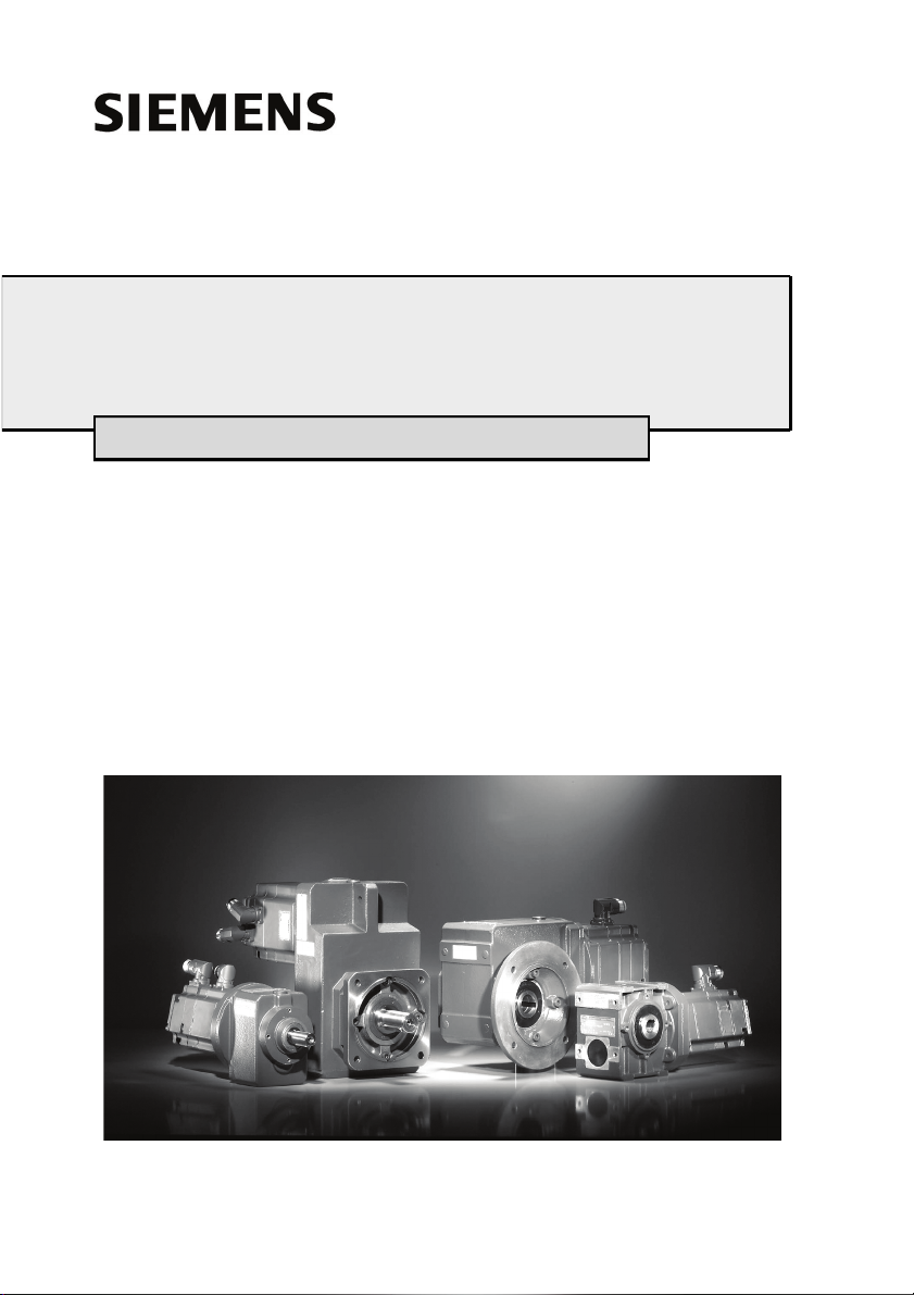
2.1.2.2 Worm gear
Fig. 1 Motor with worm gear (example)
Worm gear/motors are constructed in block design, and have one or two spur gear stages (2 or 3 stage gear) upstream of the worm unit. The output shaft outputs at an angle of
90° to the input shaft. The worm unit has a hardened, ground steel worm and bronze
worm wheel, it dampens impacts and shocks. The teeth have a narrow flank clearance.
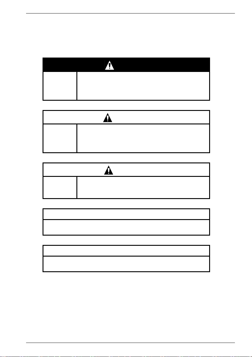
2.1.2.3 Bevel wheel gear
ENGLISH
Fig. 2 Motor with bevel wheel gear (example)
Bevel wheel gear/ motors are constructed in block design.
The gear sizes K2 to K4 not only have the bevel wheel stage but also one or two upstream spur gear stages (2 or 3-stage gear). Sizes K5 to K10 not only have the bevel
wheel stage but are also equipped with one downstream and one or two upstream spur
gear stages (3 or 4-stage gear). The output shaft is arranged 90° offset from the drive
shaft. The curved tooth bevel wheel stage allows a narrow flank clearance.
Siemens AG 610.40 064.01
13
Page 14
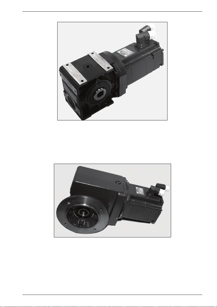
2.1.2.4 Flat gear
Fig. 3 Motor with flat gear (example)
ENGLISH
Flat gear/motors are constructed in compact block design with a 2 or 3 stage spur gear,
an extremely flat casing and a long axle distance.
The output shaft is designed as a solid or hollow shaft.
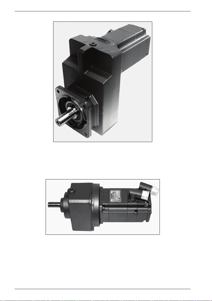
2.1.2.5 Circular gear
Fig. 4 Motor with circular gear (example)
Spur gear/ motors are constructed in compact block design with a 2 or 3 stage spur gear
transmission. The drive and output shafts are coaxial.
14 610.40 064.01 Siemens AG
Page 15
ENGLISH
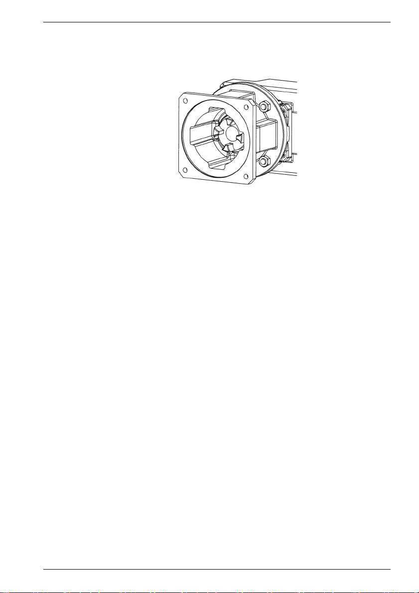
2.1.3 Motor adapter
If no direct motor gear mounting is provided, motor adapters (with a square flange) are
used for mounting servomotors (according to IEC or NEMA-C) on a gearbox.
Fig. 5 Motor adapter (example)
2.1.3.1 Motor adapter with curved tooth clutch
Servomotors are mounted on the gearbox by means of motor adapters (with a square
flange). Servomotors can be mounted if the shaft end and mounting flange have standard
true running, axial run-out deviation and coaxial qualities complying with DIN 42955-N.
The motor does not have to be oil-tight. The centering diameter must be designed with a
tolerance complying with ISO j6, the shaft end complying with tolerance ISO k6, and the
key complying with DIN 6885 sheet 1. The motor can be mounted and dismounted without coming into contact with lubricant. The motor shaft is linked to the gear input shaft by
the freely movable, torsionally rigid and maintenance-free curved tooth clutch. The clutch
runs dry and has a maximum continuous operating temperature of 80°C. The motor
adapter does not require any special maintenance.
2.1.3.2 Motor adapter with plug-in connector, zero-backlash
Motor adapters with zero backlash, axially braced, plug-in metal bellows-type clutch are
used for mounting servomotors on gearboxes. The motors preferably have smooth shafts
(without key). The clutch bush mounted on the gear side has a spring-loaded metal bellows. For this reason, standard true running, axial run-out deviation and coaxial qualities
complying with DIN 42955-N are adequate for the shaft ends and the mounting flange of
the mounted motor.
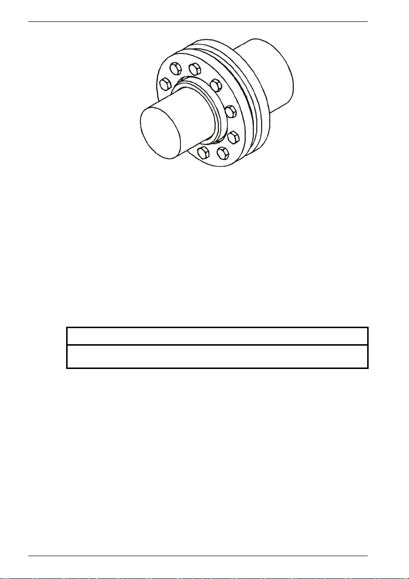
2.1.4 Hollow shaft with shrink disk
Shaft mounted gearboxes are inserted onto the drive shaft of the machine that is to be
driven. The reaction torque must be supported either by flange-mounting the gearbox on
the machine or by a torque bracket. In the case of flange mounting, the deviation from
perpendicularity between the flanged end surface on the machine and the shaft axis must
not exceed 0.03/100 mm because of the danger of distorting the bearing or causing an
impermissible bending load on the machine shaft.
Siemens AG 610.40 064.01
15
Page 16
ENGLISH
Fig. 6 Hollow shaft (example)
Shrink disc connection:
The hollow shaft is connected to the smooth machine drive shaft by frictional engagement produced by elastically constricting the hollow shaft with a shrink disk. This shafthub link has absolute zero-backlash, and is therefore also non-wearing.
It can transmit high torques and axial forces with a high degree of true-running accuracy
(as a result of its self-centering characteristic).
The hollow shaft is made of high-tensile tempering steel.
Hollow shaft models (dependent upon size of gearbox):
- Hollow shafts with slots in the shrink seating area:
Machine shaft with tolerance complying with ISO h9.
- Hollow shafts without slots in the shrink seating area:
Machine shaft with tolerance complying with ISO h6.
CAUTION
The end of the hollow shaft with the shrink disk seating must not be loaded with
a radial operational force.
16 610.40 064.01 Siemens AG
Page 17
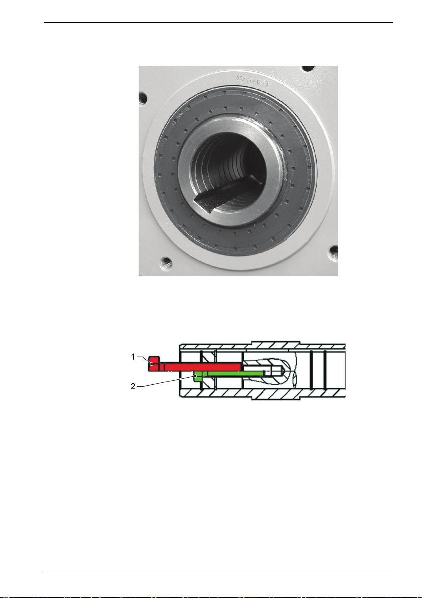
2.1.5 Hollow shaft and key link
The hollow gear shaft has a spiral groove which acts as a grease reservoir and prevents
fretting corrosion.
Fig. 7 Hollow shaft and key link
ENGLISH
The machine shaft can be dismounted with the aid of a forcing off disk (see also Chapter
4.2.2.1 “Geared motor with hollow shaft and key link”).
Fig. 8 Dismounting the machine shaft
1 Force off
2Shrink on
2.1.6 Torque bracket
A torque bracket can be mounted on three sides (GS1; GS2; GS5) of bevel gears (conical/worm gears) by screwing on a drive plate. The corresponding torque bracket can also
be mounted in two positions of rotation.
Siemens AG 610.40 064.01
17
Page 18
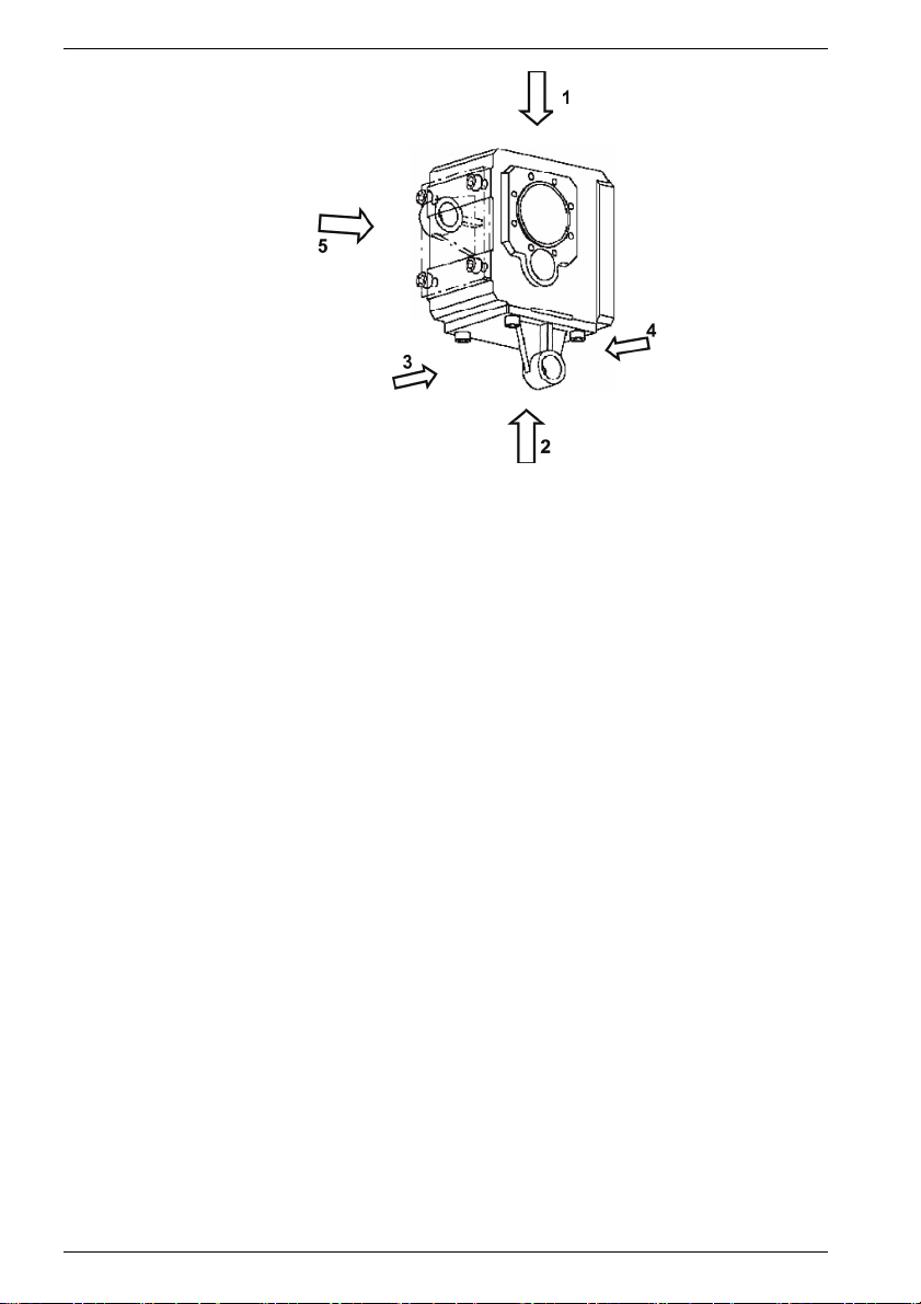
Fig. 9 Example of arrangement of the torque bracket on the side of the
gear (GS) 2; Eye of the torque bracket in the GS4 direction.
2.2 Scope of Delivery
The drive systems have been assembled individually, they have been tested and properly packed in the works.
Upon receipt of delivery, check that the delivery is complete, check for transport damage,
and whether the scope of delivery corresponds with the consignment notes.
SIEMENS cannot accept any liability for any shortages or deficiencies reported at a later
date. Any complaints must be reported to the transport company without delay.
Complaint instructions:
- Report detectable transport damage immediately to the carrier/transport company,
- Report detectable defects / incomplete delivery immediately to the responsible
SIEMENS representative.
The operating manual is part of the scope of delivery and shall therefore be kept in an
accessible place. As the delivery includes a separate type plate, the motor data must also
be kept on or near the machine or system.
ENGLISH
18 610.40 064.01 Siemens AG
Page 19
3 Technical specifications
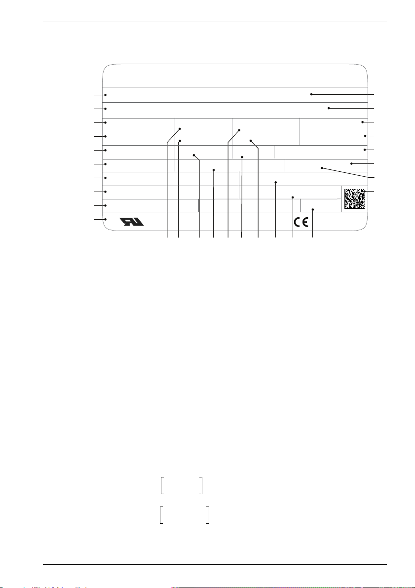
3.1 Rating plate
SIEMENS
1
3~ Motor
2
3
M
27,0
10
4
M
15,5
1N
5
Th.Cl. (F)
6
Resolver p=4
7
gear unit type: K402ANG0060
8
ratio: I=6,000
9
mounting position: any
10
Fig. 10Rating plate (example)
1 Motor type: Three-phase servomotor
2 ID No., Production number
3 Zero speed continuous torque M
4 Rated torque M
5 Temperature class
6 Encoder type code
7 Gear type code
8 Gear ratio code; [exact transmission
9 Mounting position code Geared motor
10 Standards and regulations
11 Zero-speed current I
12 Rated current I
13 Induced voltage U
14 Holding brake data
15 Maximum speed n
C US
[Nm]
ratio]
motor (gear drive)
1FK7101 - 5AF1 - 1SU5 - Z
T131 9430 01
I
Nm
Nm
11 12 13 1614 17 18 19 2015
[Nm]
N
0
[A]
N
[V]
IN
1max
19,0AA
0
I
11,8
N
U
270 V
iN
BRAKE 24VDC 17,6W 3043501
[6/1]
[A]
[rpm] of the
ENGLISH
001No. YF
Made in Germany
0
Z:
B42 + G63 + H11
n
n
IP
1max
1N
2700
3000
64
/min
/min
M
90,2 (S3-60%)Nm
2N
l
max
n
2
49,2
500
A
/min
RN 000 N01
oil type: Mobil SHC 629
quantity of oil: 2,50 l
m: kg61
EN 60034
16 Type of protection
17 Rated speed n
[rpm] of the motor
1N
(gear drive)
18 Gearbox oil name
19 Gearbox oil quantity
20 Geared motor weight m [kg]
21 Bar code
22 Geared motor version
23 Encoder version
24 PTO rated torque M
(operating mode) *)
25 PTO speed n
power take-off **)
2
26 Maximum current I
[1/min]
max
2N
[Nm];
[A]
27 Order options
28 SIEMENS motor type/ designation
28
27
26
25
24
23
22
21
M
*)
n1Nn
**)
n1Nn
Siemens AG 610.40 064.01
2N
f M1N()=
1max
1max
n
1N
=⇒≤
n
---------
2
i
n
1max
=⇒>
n
--------------
2
i
19
Page 20

3.2 Features
3.2.1 General information
The technical data of the drive is stated on the type plate.
Dimensions can be taken from the dimensional sketches in the relevant planning guide
or the DP tool "CAD-Creator".
Comply with permissible torques, make a current limitation on the servo
frequency converter if necessary.
Transport temperature -20 °C to +40 °C (-4 °F to 104 °F)
Storage temperature 0 °C to +40 °C (32 °F to 104 °F)
Ambient temperatures -15 °C to +40 °C (5 °F to 104 °F)
Installation altitude ≤up to 1000 m a.s.l,
Weight Refer to the type plate
Degree of protection as per EN 60-529 IP 65
Sound pressure level as per EN 60 034-9 approx. 75 dB(A)
Vibration severity grade as per EN 60 034-14 Grade N
True running, coaxiality, axial run-out devia-
tion as per IEC 60 072-1
ENGLISH
otherwise the rated data are reduced
to 50 °C conversion factor 0,92
to 60 °C conversion factor 0,82
2000 m conversion factor 0,94
2500 m conversion factor 0,9
Tolerance N
The dimensional sheets of the DP tool "CAD-Creator" and the "Three-phase
servomotors" operating instructions contain additional technical values.
3.2.2 Gears
NOTE
The corresponding gear size can be seen in the second item of the gear type (see
type plate, fig. 7) or the second item of the first block of the order option.
3.2.2.1 Worm gear
Lubricant see rating plate
Oil filling quantity see rating plate
Bleeding:
- gear size 0 (mounting positions 2 and 5)
- gear sizes 1 to 4
Transport lifting tackle without
20 610.40 064.01 Siemens AG
- valve open
- valve lockable
Page 21

3.2.2.2 Bevel wheel gear
Lubricant see rating plate
Oil filling quantity see rating plate
Venting (lockable)
- gear sizes 1 to 4
- gear sizes 5 to 10
Transport lifting tackle Lifting eyes (for gear sizes 5 to 10 only)
3.2.2.3 Flat gear
Lubricant see rating plate
Oil filling quantity see rating plate
Venting (lockable)
- gear sizes 1 to 4
- gear sizes 5 to 6
Transport lifting tackle Borehole for lifting eyes on the gearbox
3.2.2.4 Circular gear
Lubricant see rating plate
Oil filling quantity see rating plate
Venting (lockable)
- gear sizes 0 to 5
- gear sizes 6 to 10
Transport lifting tackle Lifting eyes (for gear sizes 7 to 10 only)
ENGLISH
- without bleeding
- with bleeding
- without bleeding
- with bleeding
frame
- without bleeding
- with bleeding
3.2.3 Motor adapter
3.2.3.1 Motor adapter with curved tooth clutch
Operating temperature - 30 °C to 100 °C
Continuous operating temperature 80 °C (max. peak temperature 120 °C)
Motor shaft with key
3.2.3.2 Motor adapter with plug-in connector, zero-backlash
Operating temperature - 30 °C to 100 °C
Continuous operating temperature 80 °C (peak temperature max. 120 °C)
Motor shaft without key
Siemens AG 610.40 064.01
21
Page 22
4 Transport, assembly
The specifications for transport, installation and assembly in the operating
instructions for the three-phase servomotor 1FK7 (order/item number
610.40 700.21) must be complied with.
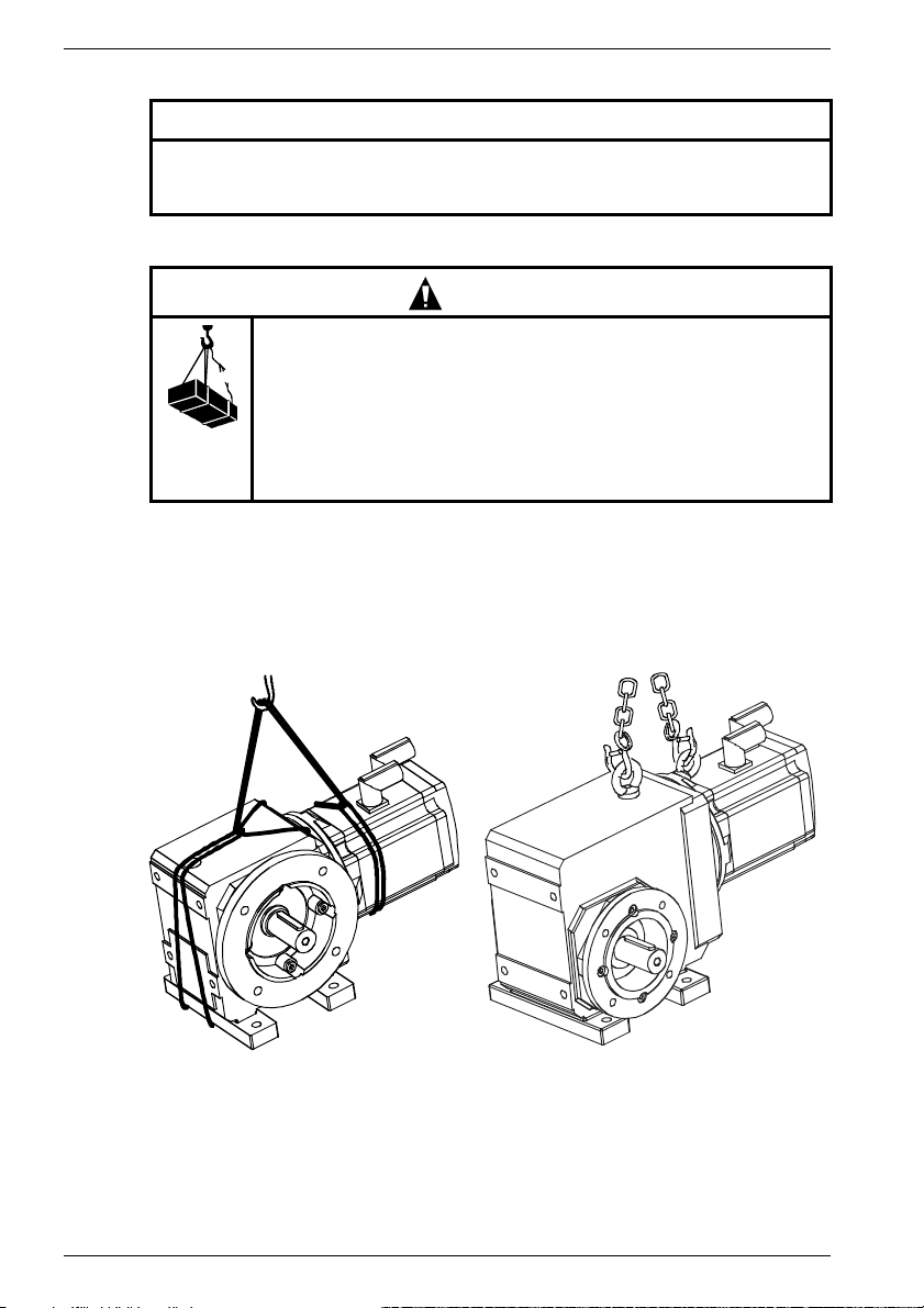
4.1 Transport, storage
Danger during lifting and transporting procedures!
Improper handling, unsuitable or defective devices, tools etc. can
cause injuries and/or property damage.
Lifting devices, floor conveyors and lifting tackle must conform to
the currently valid regulations.
The relevant safety regulations (e.g. VBG 8) for standing under
suspended loads must be complied with during assembly work on
the holding brake or on the brake motor.
Use suitable lifting tackle for transport and assembly.
Use suspension bands and lifting eyes for transporting the geared motors.
Lifting tackle as per 98/37/EU Directive for Machines, Appendix I.
Refer to the type plate for exact specifications of the weight of the motors.
Observe the transport regulations applying in the country/countries concerned.
Shafts and their bearings must not be damaged by impacts.
ENGLISH
CAUTION
WARNING
A
Fig. 11Examples for lifting and transporting
A with suspension bands (carrying rope) B with lifting eyes/chains
For transporting the unpacked drive within the works:
- lift large geared motors with lifting eyes in the ring bolts,
- lift smaller geared motors with suitable suspension bands (carrying rope) on the
geared motor.
22 610.40 064.01 Siemens AG
B
Page 23

Store in a dry, low-dust and low-vibration place (v
temperatures, see Chapter 3 “Technical specifications”.
Condensed water in the oil chamber of the gearbox leads to rusting, which must be avoided at all costs. Its intensity is determined by the degree of relative air humidity and large
temperature fluctuations.
It is necessary to contact SIEMENS Service if the gearbox is to be temporarily stored. If
long-term storage is foreseen, the gearbox must be completely filled with lubricant by the
manufacturer. This then has to be reduced to the correct quantity shown on the type plate
before the drive is started. The bare parts of the gearing must be conserved.
4.2 Installation, assembly
4.2.1 General information
Impacts on the shaft and bearings must be avoided at all costs as they damage
the bearing race. Do not exceed the permissible axial and radial forces on the
shaft end stated in the configuration specification.
The protective lacquer on the ends of the shaft and centering shoulders must be completely removed before erection/assembly.
If solvents are used, they must not be allowed to come into contact with the lip
seals of the shaft seal rings.
Mounting position, mounting location
The drive may only be mounted in the ordered mounting position.
If the mounting position is changed, the internal construction of the gearbox and the
quantity of lubricant may also have to be changed. The lubrication fittings also have to
be exchanged. In such a case, it is absolutely essential to contact SIEMENS Service.
ENGLISH
NOTICE
CAUTION
< 0,2 mms-1); transport and storage
eff
CAUTION
It must be ensured that air can circulate freely in order to prevent heat
accumulating in the entire gearbox.
Bleeding
Depending upon the design /gear size, some geared motors are vented (see technical
data). The design of the venting valve for worm gears depends upon the mounting position.
CAUTION
In the case of a lockable venting valve, it must be opened without fail before
starting up the drive by turning the knurled knob to the left (corresponding to the
symbol on the knurled knob).
In the case of a loosely attached venting valve, it must be exchanged in the
intended mounting position for the screw plug located in the gearbox.
Siemens AG 610.40 064.01
23
Page 24
ENGLISH
Installation
The subframe for attaching the foot or flanged gearbox must be level and torsionally rigid
in order to prevent strain on the gearbox or output shaft bearing.
The tapped center hole of the output shaft (according to DIN332 sheet 2) is provided both
for shrinking on and for axially attaching transmission elements (gear wheel, chain wheel,
belt pulley, clutch hub) by a central screw.
Shaft ends up to a diameter of 55 have tolerance ISO k6, over 55 have ISO m6.
The key complies with DIN 6885 sheet 1.
4.2.2 Specific features
4.2.2.1 Geared motor with hollow shaft and key link
Shaft mounted gearboxes are inserted onto the drive shaft of the machine that is to be
driven. The reaction torque must be supported either by flange-mounting the gearbox or
by a torque bracket.
In the case of flange mounting, the deviation from perpendicularity between the flanged
end surface on the machine and the shaft axis must not exceed 0.03/100 mm because
of the danger of distorting the bearing or causing an impermissible bending load on the
machine shaft.
The hollow shaft borehole is designed to comply with tolerance ISO H7 and the keyway
with DIN 6885 sheet 1. The machine shaft must comply with ISO k6. The machine shaft
must have a tapped center hole complying with DIN 332 sheet 2.
The shrink on/forcing off disk fitted in the hollow shaft is provided for axially attaching the
gear by a central screw.
Assembly/shrinking of the gear onto the machine shaft:
- Paint the machine shaft with MoS2 paste.
- Paint the hollow shaft spiral groove and keyway with rust preventing grease.
- Shrink the gear on by means of the central screw. Do not hit with a hammer!
CAUTION
Never slip on a dry gear, as otherwise it will be impossible to pull it off to make a
repair because it will have rusted on.
Disassembly:
- Force the gear off by means of a forcing off disk and a suitable forcing-off screw.
Protect the centering of the machine shaft with a support.
- If the shaft is stuck, we recommend allowing rust dissolving oil to work into the
machined seat on the shaft ends for a lengthy period of time.
4.2.2.2 Geared motors with hollow shaft and shrink disk connection
The instructions listed above apply here (see Chapter 4.2.2.1 “Geared motor with hollow
shaft and key link”)! These hints must be observed without fail!
In the case of gears supplied with a shrink disk, this is already mounted on the end of the
hollow shaft and is therefore ready for assembly (conical surfaces and screws of the
shrink disk have been greased in the works).
CAUTION
Do not on any account tighten the locking screws of the shrink disk before the
machine shaft has been mounted as otherwise the inner ring and the hollow shaft
hub will be plastically deformed.
24 610.40 064.01 Siemens AG
Page 25

ENGLISH
Preparations for assembly:
1. Degrease the machine shaft in the pressing area of the shrink disk.
2. Remove the sealing cap and the covering cap from the hollow shaft and shrink disk
respectively.
3. Remove conservation lacquer from the shrink seating and seating face of the hollow
shaft borehole.
The hollow shaft borehole and the machine shaft must be grease-free in the area
of the shrink seating.
Assembly:
1. Slip the gear onto the machine shaft (do not hit with a hammer) and bring into
position.
2. In the case of a slotted hollow shaft, take note of the position of the shrink disk.
3. Tighten the hexagonal screws in the shrink disk evenly one after the other (not crisscross) in several cycles (tightening them by between a quarter and half turn each
time) until all the screws have the necessary pre-tensioning given by the specified
tightening torque.
It must be ensured that the two conical spring washers are lying plane-parallel to one
another.
4. Check the tightening torque with a torque wrench as shown in Table 1.
Screws
Hexagonal wrench
Tightening torque [Nm]
(at µ
= 0,1)
ges
M5
8.8M610.9/12.9M810.9/12.9
8 10131719
5 12/14 30/35 59/69 100/120
M10
10.9/12.9
M12
10.9/12.9
Table 1: Tightening torque
WARNING
Hazard from rotating rotor/freely revolving transmission shaft.
Attach suitable protective devices (protection against accidental
contact/covers) before starting up the output elements.
Disassembly:
1. Secure the drive against being switched on unintentionally.
2. Remove the covers from the shrink disk.
Loosen the screws holding the shrink disk one after the other in several cycles,
starting with about one quarter turn (strain washer can jam).
WARNING
There is an injury hazard!
Do not unscrew the screws completely out of their tapped holes.
The strain washer may spring off.
3. After the screws and strain washers have been loosened, the frictional engagement
between the hollow shaft and machine shaft is released.
Insert a retaining ring into the available slot if necessary for pulling off the gear.
Siemens AG 610.40 064.01
25
Page 26
ENGLISH
4. To clean the shrink disk, relubricate screws and conical surface with MoS2 based
solid lubricant.
CAUTION
Before switching the motor on, ensure that:
- the drive does not traverse against a block
- all protective and safety devices are properly installed, even for trial
operations
- the direction of rotation of the drive is correct (important where there is a
back-run safety device)
4.2.2.3 Geared motor and motor adapter with curved tooth clutch
Preparations for assembly:
1. Unscrew the cardboard cover from the adapter casing, and take the clutch hub for the
motor out of the casing. Put the plastic clutch bush onto the counter hub.
2. Check whether the borehole diameter and the keyway fit the clutch hub for the motor
shaft. The borehole of the clutch hub has tolerance ISO H7; the keyway is
manufactured in accordance with DIN 6885 sheet 1.
According to the IEC regulation, the shaft shoulder and flange surface of the
motor must lie in the same plane. The motor shaft must not be longer than
stated in the standard.
Assembly:
1. Lightly grease the motor shaft.
2. Press the clutch hub onto the motor shaft as far as the shaft shoulder.
3. Securely tighten the set screw on the clutch hub.
4. Carefully put the motor onto the adapter casing so that the curved teeth of the clutch
hub easily mesh with the internal toothing of the plastic sleeve.
5. Screw the motor securely to the adapter casing.
The quality of the fixing screws (metric and UNC thread) and the tightening torques
must correspond to Table 2.
Screws
Tightening torque [Nm]
M5
8.8
25 49 85
M10
8.8
M12
8.8
Table 2: Tightening torque
4.2.2.4 Geared motor and motor adapter with plug-in connector, zero-backlash
NOTE
If the assembly instructions are followed, the plug-in connectors are
permanently fixed and maintenance-free.
Preparations for assembly:
The motor shaft shoulder and motor flange surface must lie in one plane (+
ensures the correct axial pre-tensioning of the clutch.
If the shaft shoulder is set back, the offset must be compensated by shims. No parts such
as screws etc. may project over the flange surface in the flange area of the motor.
26 610.40 064.01 Siemens AG
0.5 mm). This
Page 27

ENGLISH
The untensioned clutch hub has a fitting clearance to the motor shaft of 0.01 to 0.05 mm.
As a consequence of the frictional hub-clamp connection and the axial pre-tensioning of
the conical plug-in segments, the plug-in connector works with absolute zero-backlash.
Assembly:
1. Degrease the motor shaft and the clutch hub on the motor side.
2. Put the slotted clutch hub on the motor shaft and slide it against the shaft shoulder;
check the axial position of the hub.
3. Tighten the locking screw as shown in Table 3.
Screws
Tightening torque [Nm]
M5
8.8
61025
M6
8.8
M8
8.8
Table 3: Tightening torque
4. Screw the motor to the adapter casing, tighten the fixing screws as shown in Table 3.
CAUTION
When setting the motor on the adapter casing, the plastic cams of the motor-side
hub must be carefully inserted into the corresponding recesses in the gear side
clutch bush so that the metal bellows are not compressed or bent.
Siemens AG 610.40 064.01
27
Page 28
5 Start-up
The specifications for starting up / for connecting the motor in the operating
instructions for the three-phase servomotor 1FK7 (order/item number 610.40
700.21) must be complied with.
For the lubrication instructions see Chapter 7.1.2 “Lubrication”
The gear is not self-locking.
5.1 Checks before starting up
Thermal hazard from hot surfaces!
The surface temperatures of the motors may not exceed 140 °C.
Do not touch hot surfaces!
Protection must be provided against accidental contact if necessary.
Temperature-sensitive components (electric lines, electronic
components) must not touch hot surfaces.
Before starting up, ensure that
- all connections have been properly made, and the plug connectors are secured
against working loose.
- all motor protection devices are active,
- the drive is not blocked,
- no other possible sources of danger are present,
- the drive is undamaged (no damage from transport/storage),
- the keys in the shaft end (if present) are secured against being thrown out,
ENGLISH
CAUTION
CAUTION
- the direction of rotation of the drive is correct (important where there is a back-run
safety device).
WARNING
Hazard from rotating rotor/freely revolving transmission shaft.
Secure output elements with suitable protective devices (protection
against accidental contact).
Secure key (if present) against being thrown out.
5.2 Start-up
DANGER
Electrical connections must be made by specialist personnel in accordance with
the currently valid regulations (refer to DINVDE 0105 or IEC 364 for the
regulations concerning skilled workers).
The motor winding must be protected against thermal overload by thermal
contacts or PTC thermistor probes or similar.
The guarantee for the motor winding lapses if there is no motor protection.
28 610.40 064.01 Siemens AG
Page 29

ENGLISH
6 Instructions in case of faults
CAUTION
The instructions for faults contained in the operating instructions for the threephase servomotor 1FK7 (order/item number 610.40 700.21) must be complied
with.
6.1 General instructions for rectifying faults
Refer to Table 4 first if there are deviations from normal operation or faults. Contact the
works, please also refer to the relevant section of the operating manual for the components of the entire drive system.
Do not disable the protective devices, even in trial operation.
Consult the manufacturer or the SIEMENS service center when necessary.
- For start up, system motor converter: A&D Hotline +49 180 50 50 222
- For motor / motor components: Contact in the works +49 174-3110669
They will inform the customer of the nearest service partner if further action is required.
Fault Cause Remedy
Irregular running Inadequate screening of the
Vibrations Coupling elements or driven
Running noises Foreign bodies inside the
Motor overheats
(surface temperature
>140 °C)
Temperature monitoring responds
Table 4: Troubleshooting
motor or encoder cables.
Amplification of the drive controller too high
machine are badly balanced
Inadequate alignment of the
drive train
Fixing screws are loose Check and tighten screw connec-
motor
Bearing damage Repair by the manufacturer
Drive overloaded Check load
Heat dissipation impaired by
deposits
Check screening and grounding
Adjust controller (see converter
operating manual)
Rebalance
Realign the machine set
tions
Repair by the manufacturer
(see rating plate)
Clean surface of drives,
Ensure that the cooling air can flow
freely in and out
6.2 Spare parts
The following must be stated when ordering spare parts:
- Item no. of the part in the illustration of the spare parts list (request a copy if required)
- Type designation stated on the type plate on the geared motor
- Serial number stated on the type plate on the geared motor
NOTE
The spare parts lists are not assembly instructions! They are not binding for
assembly purposes. Only original parts may be used as spare parts.
We give no warranty and accept no liability for damage resulting from any parts
not supplied by us.
Siemens AG 610.40 064.01
29
Page 30
ENGLISH
7 Inspection, maintenance, disposal
7.1 Maintenance / repair
7.1.1 General instructions
Clean wherever and whenever the degree of contamination makes it necessary in order
to ensure that the waste heat is adequately dissipated. As the operating conditions vary
greatly, one can only cite general intervals for fault-free operation.
Guidelines:
- Bearing service life 20,000 hours
- Radial shaft seals approx. 5,000 hours with oil lubrication
WARNING
The motors’ rotors contain permanent magnets with high magnetic flux densities
which exert strong attractive forces on ferromagnetic bodies.
People fitted with a heart pacemaker are at risk in the vicinity of a disassembled
rotor. Data stored on electronic data media may be destroyed.
NOTICE
The encoder system must be readjusted each time after the motor has been
disassembled.
The maintenance of the geared motors is kept to a minimum by their design
concept (see Chapter 7.1.2 “Lubrication”).
All components subject to operational wear (for example friction linings of brakes)
must be included in the regular maintenance measures.
SIEMENS service partners are available for all maintenance work on gears (see Chapter
6 “Instructions in case of faults”).
DANGER!
Electric shock hazard!
When the rotor is rotating, the motor terminals carry a dangerous
voltage.
Stop the motor before commencing any electrical work.
Only use trained, qualified personnel for assembly work on the
converters and plugs.
Observe the regulations for working in electrotechnical plants.
Safety rules for working in electrical installations as per
EN 50110-1 (DIN VDE 0105-100):
- Work always with the equipment electrically dead.
- Isolate from electrical supply.
- Secure against switching on again.
- Check electrical deadness.
- Earth and short-circuit.
- Cover or cordon off adjacent parts which are electrically live.
- Release for work.
- Connect the PE conductor to
30 610.40 064.01 Siemens AG
Page 31

7.1.2 Lubrication
The points "mounting position" and "venting" in must be complied with Chapter 4.1
“Transport, storage”.
POLYGLYCOL based lubricant must not be mixed with mineral oil. The quantity
of lubricant to fill (quantity of oil) depends upon the position in which the gearbox
is mounted, and is stated on the type plate.
All used lubricants, cleansers, containers etc. must be disposed of according to
the legal regulations.
7.1.2.1 Motor with worm gear
Unless otherwise stated on the type plate, the gears are filled with high pressure gear oil.
The oil must be changed after about 5,000 operating hours, but after 2,000 operating
hours when used in damp rooms (this must be stipulated in the order!).
7.1.2.2 Motor with bevel wheel gear
Unless otherwise stated on the type plate, the gears are filled with high pressure gear oil.
Gears of sizes 1 to 4 have long-time lubrication, and do not require any maintenance if
used for the intended purpose.
Gears of sizes 5 to 10 need an oil change after 5, 000 operating hours, but after 2,000
operating hours when used in damp rooms (this must be stipulated in the order!).
7.1.2.3 Motor with flat gear
Unless otherwise stated on the type plate, the gears are filled with high pressure gear oil.
The gears have long-time lubrication, and do not require any maintenance if used for the
intended purpose.
7.1.2.4 Motor with circular gear
Unless otherwise stated on the type plate, the gears are filled with high pressure gear oil.
Gears of sizes 0 to 5 have long-time lubrication, and do not require any maintenance if
the drive is used for the intended purpose.
Gears of sizes 6 to 10 need an oil change after 5, 000 operating hours, but after 2,000
operating hours when used in damp rooms (this must be stipulated in the order!).
ENGLISH
NOTICE
Siemens AG 610.40 064.01
31
Page 32

ENGLISH
7.2 Disposal
Motors must be disposed of in accordance with the national and local regulations by
putting them into the standard recycling process or by returning them to the manufacturer.
The following points must be observed when disposing of the motors:
- Dispose of oil in accordance wit the old oil ordinance (for example no mixing with
solvents, cold cleansers or lacquer residues)
- Separate components for recycling into:
- Electronic scrap (encoder electronics)
- scrap iron
- aluminium
- nonferrous metals (worm wheels, motor windings)
- permanent magnets
WARNING
Danger of crushing injuries. People with heart pacemakers must keep well away
as they at risk from the effects of the permanent magnets.
8 Other applicable documentation
These operating instructions are valid in conjunction with the following documentation:
- Project planning guide 1FK7.,
Ordering / Item number 6SN1197-0AD06-0AP0
- Operating manual, three-phase servomotor 1FK7., Three-phase servomotor 1FK7.,
Ordering / Item number 610.40 700.21
- Maintenance manuals, three-phase servomotor 1FK7., Three-phase servomotor
1FK7.,
Ordering / Item number 610.43 430.21
32 610.40 064.01 Siemens AG
Page 33

DEUTSCH
Diese Betriebsanleitung enthält Hinweise, die Sie zu Ihrer persönlichen Sicherheit sowie
zur Vermeidung von Sachschäden beachten müssen. Die Hinweise zu Ihrer persönlichen
Sicherheit sind durch ein Warndreieck hervorgehoben, Hinweise zu alleinigen
Sachschäden stehen ohne Warndreieck. Je nach Gefährdungsgrad werden sie
folgendermaßen dargestellt:
GEFAHR
bedeutet, dass Tod, schwere Körperverletzung oder
Piktogramm
erheblicher Sachschaden eintreten werden, wenn die
entsprechenden Vorsichtsmaßnahmen nicht getroffen
werden.
WARNUNG
bedeutet, dass Tod, schwere Körperverletzung oder
Piktogramm
erheblicher Sachschaden eintreten können, wenn die
entsprechenden Vorsichtsmaßnahmen nicht getroffen
werden.
VORSICHT
Piktogramm
mit Warndreieck bedeutet, dass eine leichte
Körperverletzung eintreten kann, wenn die
entsprechenden Vorsichtsmaßnahmen nicht getroffen
werden.
VORSICHT
ohne Warndreieck bedeutet, dass ein Sachschaden eintreten kann,
wenn die entsprechenden Vorsichtsmaßnahmen nicht getroffen
werden.
ACHTUNG
bedeutet, dass ein unerwünschtes Ereignis oder Zustand eintreten
kann, wenn der entsprechende Hinweis nicht beachtet wird.
Siemens AG 610.40 064.01
33
Page 34

DEUTSCH
Qualifiziertes Personal
Inbetriebsetzung und Betrieb des Gerätes dürfen nur von qualifiziertem Personal
vorgenommen werden. Qualifiziertes Personal im Sinne der sicherheitstechnischen
Hinweise dieser Betriebsanleitung sind Personen, die die Berechtigung haben, Geräte,
Systeme und Stromkreise gemäß den Standards der Sicherheitstechnik in Betrieb zu
nehmen, zu erden und zu kennzeichnen.
Bestimmungsgemäßer Gebrauch
Beachten Sie:
Das Gerät darf nur für die im Katalog und in der Projektierungsanleitung vorgesehenen
Einsatzfälle und nur in Verbindung mit von Siemens empfohlenen bzw. zugelassenen
Fremdgeräten und -komponenten verwendet werden.
Der einwandfreie und sichere Betrieb des Produktes setzt sachgemäßen Transport,
sachgemäße Lagerung, Aufstellung und Montage sowie sorgfältige Bedienung und
Instandsetzung voraus.
Haftungsausschluss
Wir haben den Inhalt der Druckschrift geprüft. Dennoch können Abweichungen nicht
ausgeschlossen werden, so dass wir für die vollständige Übereinstimmung keine Gewähr
übernehmen. Die Angaben in dieser Druckschrift werden regelmäßig überprüft, und
notwendige Korrekturen sind in den nachfolgenden Auflagen enthalten. Für
Verbesserungsvorschläge sind wir dankbar.
© Copyright Siemens AG 2005. All rights reserved
Weitergabe sowie Vervielfältigung dieser Unterlage, Verwertung und Mitteilung ihres
Inhalts ist nicht gestattet, soweit nicht ausdrücklich zugestanden. Zuwiderhandlungen
verpflichten zum Schadenersatz.
Alle Rechte vorbehalten, insbesondere für den Fall der Patenterteilung oder
GM-Eintragung.
Siemens AG
Bereich Automatisierungs- und Antriebstechnik
Geschäftsgebiet Motion Control Systeme (MC)
D-97615 Bad Neustadt an der Saale
34 610.40 064.01 Siemens AG
Page 35

DEUTSCH
1 Allgemeine Sicherheitshinweise
Diese Betriebsanleitung enthält alle erforderlichen Informationen über Transport, Aufstellung, Inbetriebnahme, Wartung usw. der Getriebemotoren.
Diese Betriebsanleitung gilt in Verbindung mit der SIEMENS-Projektierungsanleitung sowie Betriebsanleitung „Drehstrom-Servomotoren“.
Die Erfüllung eventueller Garantieansprüche setzt die genaue Einhaltung der Angaben
und Hinweise dieser Betriebsanleitung voraus.
Zur Vermeidung von Gefährdungen jeglicher Art bei Transport, Lagerung, Anbau,
Inbetriebnahme, Wartung usw. müssen die Sicherheits- und Gefahrenhinweise
dieser Betriebsanleitung sowie der Betriebsanleitung für Drehstrom-Servomotoren (1FK7.) unbedingt eingehalten werden! Das Nichteinhalten kann schwere Körperverletzungen oder Sachschäden zur Folge haben.
Sichern Sie für Ihr Endprodukt die Einhaltung aller bestehenden Rechtsvorschriften! Beachten Sie die verbindlichen nationalen, örtlichen und anlagenspezifischen
Vorschriften!
Die Inbetriebnahme ist so lange untersagt, bis die Konformität des Endprodukts
mit den geltenden Richtlinien festgestellt ist.
Mechanische Gefährdungen, welche z.B. von einer freidrehenden Getriebewelle aus-
gehen, sind durch geeignete Schutzvorrichtungen auszuschließen! Alle Passfedern in
Wellen müssen gesichert sein!
Elektrische Gefährdungen sind durch genaue Beachtung der in Kapitel “Inbetriebnahme” gegebenen Anweisungen auszuschließen!
Die Läufer der Motoren enthalten Permanentmagnete mit hohen magnetischen Flussdichten und starken Anziehungskräften zu ferromagnetischen Körpern.
In der Nähe eines demontierten Läufers sind Personen mit Herzschrittmacher gefährdet.
Auf elektronischen Datenträgern gespeicherte Daten können zerstört werden.
Der Einsatz in explosionsgefährdeten Bereichen ist verboten, sofern nicht ausdrücklich
bestätigt.
Für den Betrieb außerhalb des zulässigen Temperaturbereiches muss der Antrieb
werkseitig dafür ausgerüstet sein.
Thermische Gefährdung durch Berühren des Getriebe-/Motorengehäuses mit bloßer
Hand! Es kann bei entsprechender Betriebstemperatur zu Verbrennungen oder zu
schreckhaften Reaktionen kommen! Die Oberflächentemperatur der Motoren kann bis
140 °C, die der Getriebe bis 90 °C betragen.
Berühren Sie nicht heiße Oberflächen!
Temperaturempfindliche Bauteile (elektrische Leitungen, elektronische Bauteile) dürfen
nicht an heißen Oberflächen anliegen. Überhitzung der Motoren kann Zerstörung der
Wicklungen und Lager und Entmagnetisierung der Permanentmagnete bewirken.
Betreiben Sie die Motoren nur mit wirksamer Temperaturkontrolle!
Bestimmungsgemäßer Gebrauch
Das Einhalten aller Vorgaben der Betriebsanleitung und der Projektierungsanleitung
„Drehstrom-Servomotoren“ ist Bestandteil der bestimmungsgemäßen Verwendung.
Die Getriebe/Getriebemotoren sind für die im Katalog angegebenen zulässigen Leistungen und Belastungen konzipiert. Die Getriebemotoren dürfen nur für den Einsatzfall verwendet werden, für den sie unter Berücksichtigung aller Betriebsfaktoren projektiert
wurden. Jegliche Überlastung der Antriebe gilt als nicht bestimmungsgemäße Verwendung. Eigenmächtige Veränderungen am gesamten Antrieb schließen eine Haftung des
Herstellers für daraus entstehende Schäden aus.
Siemens AG 610.40 064.01
35
Page 36

2 Angaben zum Produkt
2.1 Produktbeschreibung
2.1.1 Allgemeines
Die Getriebemotoren bestehen aus einem Drehstrom-Servomotor (1FK7.) mit
angeflanschtem Getriebe. Die Drehstrom-Servomotoren werden mit montierten Getriebe
ausgeliefert. Einige Ausführungen werden mit zusätzlicher Kupplung ausgeliefert.
Es ist möglich den Drehstrom-Servomotor mit allen beschriebenen Getrieben/
Motoradaptern (Kupplungen) zu kombinieren. Dazu muss die Projektierung (Auswahl
der Kombination Drehstrom-Servomotor und Getriebe/Kupplung) anwenderbezogen
realisiert werden.
Die Drehstrom-Servomotoren (1FK7.) sind permanentmagneterregte DrehstromSynchron-Motoren (Drehstrom-Servomotoren) zum Betrieb mit motorgesteuerten Pulswechselrichtern nach dem Sinusstromprinzip. Die Motoren sind vorgesehen für Antrieb
und Positionierung von Werkzeug- und Produktionsmaschinen sowie Robotern und
Handhabungsgeräten.
2.1.2 Getriebe
2.1.2.1 Allgemeines
Die Getriebe kommen in verschiedenen Ausführungen und Bauformen zum Einsatz.
Die ins Langsame übersetzenden Getriebestufen reduzieren die meist hohe Eintriebsdrehzahl auf die gewünschte niedrigere Abtriebsdrehzahl. Das Eintriebsdrehmoment
vervielfacht sich dabei um die Übersetzung auf das Abtriebsdrehmoment (vermindert um
den geringen Wirkungsgradverlust des Getriebes).
Ausführung mit Bauformen Getriebewellenformen
Schneckengetriebe und
Kegelradgetriebe
Flachgetriebe - Flanschausführung
Stirnradgetriebe - Fußausführung
- Gewindelochkreis
- Flanschausführung
- Fußausführung und
- Fußausführung und
- Gewindelochkreis
- Gewindelochkreis
- Flanschausführung
- Fußausführung und
- Fußausführung und
DEUTSCH
Gewindelochkreis
Flanschausführung
Gewindelochkreis
Flanschausführung
- Vollwelle mit Passfeder
- Hohlwelle mit
Passfedernut
- Hohlwelle mit
Schrumpfscheibe
- Vollwelle mit/ohne
Passfeder
- Hohlwelle mit
Passfedernut
- Hohlwelle mit
Schrumpfscheibe
- Vollwelle mit/ohne
Passfeder
HINWEIS
Die jeweilige Bauform bzw. Einbaulage ist dem Typenschild zu entnehmen.
Die Schmierstoff-Füllmenge (Ölmenge) ist von der Getriebe-Einbaulage
abhängig und auf dem Typschild angegeben.
36 610.40 064.01 Siemens AG
Page 37

2.1.2.2 Schneckengetriebe
Fig. 1 Motor mit Schneckengetriebe (Beispiel)
Schneckengetriebe/-motoren sind in Blockbauweise aufgebaut und haben zum Schneckensatz eine oder zwei vorgeschaltete Stirnradstufen (2- oder 3-stufiges Getriebe). Die
Abtriebswelle treibt im Winkel von 90° zur Eintriebswelle aus. Der Schneckensatz mit gehärteter und geschliffener Stahlschnecke und Bronze- Schneckenrad wirkt dämpfend bei
Stößen und Erschütterungen. Die Verzahnungen haben enges Flankenspiel.
2.1.2.3 Kegelradgetriebe
DEUTSCH
Fig. 2 Motor mit Kegelradgetriebe (Beispiel)
Kegelradgetriebe/-motoren sind in Blockbauweise aufgebaut.
Die Getriebegrößen K2 bis K4 haben zusätzlich zur Kegelradstufe eine oder zwei vorgeschaltete Stirnradstufen (2- oder 3-stufiges Getriebe). Die Größen K5 bis K10 sind zusätzlich zur Kegelradstufe mit einer nachgeschalteten und einer oder zwei
vorgeschalteten Stirnradstufen ausgestattet (3- oder 4-stufiges Getriebe). Die Abtriebswelle ist zur Antriebswelle um 90° versetzt angeordnet. Die bogenverzahnte Kegelradstufe ermöglicht ein enges Flankenspiel.
Siemens AG 610.40 064.01
37
Page 38

2.1.2.4 Flachgetriebe
Fig. 3 Motor mit Flachgetriebe (Beispiel)
DEUTSCH
Flachgetriebe/-motoren sind in kompakter Blockbauweise mit 2- oder 3-stufiger Stirnradübersetzung, extrem flachem Gehäuse und großer Achsdistanz aufgebaut.
Die Abtriebswelle ist als Vollwelle oder Hohlwelle ausgeführt.
2.1.2.5 Stirnradgetriebe
Fig. 4 Motor mit Stirnradgetriebe (Beispiel)
Stirnradgetriebe/-motoren sind in kompakter Blockbauweise mit 2- oder 3-stufiger Stirnradübersetzung aufgebaut. Antriebs- und Abtriebswelle liegen koaxial.
38 610.40 064.01 Siemens AG
Page 39

DEUTSCH
2.1.3 Motoradapter
Ist kein direkter Motor-Getriebeanbau vorgesehen, werden Motoradapter (mit quadratischem Flansch) für den Anbau von Servomotoren (nach IEC bzw. NEMA-C) an einem
Getriebe eingesetzt.
Fig. 5 Motoradapter (Beispiel)
2.1.3.1 Motoradapter mit Bogenzahnkupplung
Über Motoradapter (mit quadratischem Flansch) werden Servomotoren an das Getriebe
angebaut. Anbaubar sind Servomotoren mit normaler Rundlauf-, Planlauf- und Koaxialitätsgüte nach DIN 42955-N für Wellenende und Befestigungsflansch. Öldichtheit des
Motors ist nicht erforderlich. Der Zentrierdurchmesser muss nach Toleranz ISO j6, das
Wellenende nach Toleranz ISO k6 und die Passfeder nach DIN 6885 Bl.1 ausgeführt
sein. Der An- und Abbau des Motors ist möglich, ohne mit Schmierstoff in Berührung zu
kommen. Die Motorwelle wird mit der Getriebe-Eintriebswelle durch die freibewegliche,
drehsteife und wartungsfreie Bogenzahnkupplung verbunden. Die Kupplung läuft trocken und lässt eine Dauerbetriebstemperatur bis 80 °C zu. Der Motoradapter bedarf keiner speziellen Wartung.
2.1.3.2 Motoradapter mit Steckkupplung, spielfrei
Motoradapter mit spielfreier, axial verspannter, steckbarer Metallbalgkupplung werden
zum Anbau von Servomotoren an Getriebe eingesetzt. Die Motoren haben vorzugsweise
glatte Wellen (ohne Passfeder). Die auf der Getriebeseite sitzende Kupplungshülse ist
mit einem federnden Metallbalg versehen. Aus diesem Grund genügt für die Wellenenden und den Befestigungsflansch der angebauten Motoren normale Rundlauf-, Planlaufund Koaxialitätsgüte nach DIN 42955-N.
2.1.4 Hohlwelle mit Schrumpfscheibe
Aufsteckgetriebe werden auf die Antriebswelle der anzutreibenden Maschine gesteckt.
Das Reaktionsmoment muss entweder durch Anflanschung des Getriebes an die Maschine oder über eine Drehmomentstütze abgestützt werden. Bei Flanschbefestigung
darf wegen der Gefahr des Verspannens der Lagerung bzw. der unzulässigen Biegebelastung der Maschinenwelle die Flanschanschlussfläche an der Maschine eine Rechtwinkeligkeitsabweichung zur Wellenachse von 0,03/100 mm nicht überschreiten!
Siemens AG 610.40 064.01
39
Page 40

DEUTSCH
Fig. 6 Hohlwelle (Beispiel)
Schrumpfscheibenverbindung:
Die Verbindung der Hohlwelle mit der glatten Maschinen-Antriebswelle wird über Reibschluss durch elastisches Einschnüren der Hohlwelle mittels Schrumpfscheibe hergestellt. Diese Welle-Nabe-Verbindung ist absolut spielfrei und damit auch verschleißfrei.
Sie kann große Drehmomente und Axialkräfte bei hoher Rundlaufgenauigkeit (infolge ihrer selbstzentrierenden Eigenschaft) übertragen.
Die Hohlwelle ist aus hochfestem Vergütungsstahl gefertigt.
Hohlwellenausführungen (abhängig von der Getriebebaugröße):
- Hohlwellen mit Schlitzen im Schrumpfsitzbereich:
Maschinenwelle in Toleranz ISO h9!
- Hohlwellen ohne Schlitze im Schrumpfsitzbereich:
Maschinenwelle in Toleranz ISO h6!
VORSICHT
Die Hohlwelle darf auf der Seite, auf der die Schrumpfscheibe sitzt, nicht mit
einer radialen Betriebskraft belastet werden!
40 610.40 064.01 Siemens AG
Page 41

DEUTSCH
2.1.5 Hohlwelle mit Passfederverbindung
Die Getriebehohlwelle ist mit einer Spiralnut versehen, die als Fettkammer wirkt und somit Passungsrost vorbeugt.
Fig. 7 Hohlwelle mit Passfederverbindung
Die Demontage der Maschinenwelle ist mittels einer Abdrückscheibe möglich
(siehe auch Kapitel 4.2.2.1 “Getriebemotor mit Hohlwelle mit Passfederverbindung”).
Fig. 8 Demontage der Maschinenwelle
1 Abdrücken
2 Aufziehen
2.1.6 Drehmomentstütze
Die Anordnung einer Drehmomentstütze bei Winkelgetrieben (Kegel- / Schneckengetriebe) ist an 3 Getriebeseiten (GS1; GS2; GS5) durch Anschrauben einer Mitnahmeplatte
möglich. Weiterhin ist die Anordnung der jeweiligen Drehmomentstütze in 2 Drehpostionen durchführbar.
Siemens AG 610.40 064.01
41
Page 42

Fig. 9 Beispiel-Anordnung der Drehmomentstütze an der Getriebeseite (GS) 2;
Auge der Drehmomentstütze in Richtung GS4.
2.2 Lieferumfang
Die Antriebssysteme sind individuell zusammengestellt, sie wurden im Werk geprüft und
ordnungsgemäß verpackt.
Überprüfen Sie nach Erhalt der Lieferung diese auf Vollständigkeit, Transportschäden
und ob der Lieferumfang mit den Warenbegleitpapieren übereinstimmt.
Für nachträglich reklamierte Mängel übernimmt SIEMENS keine Gewährleistung. Eventuelle Beanstandungen sind dem Transportunternehmen umgehend zu melden.
Reklamieren Sie:
- erkennbare Transportschäden sofort beim Anlieferer/Transportunternehmen,
- erkennbare Mängel/unvollständige Lieferung sofort bei der zuständigen
SIEMENS-Vertretung.
Die Betriebsanleitung ist Bestandteil des Lieferumfanges und somit zugänglich aufzubewahren. Das der Lieferung lose beigefügte Typenschild ist dafür vorgesehen, die Motordaten zusätzlich an oder bei der Maschine oder Anlage aufzubewahren.
DEUTSCH
42 610.40 064.01 Siemens AG
Page 43

3 Technische Daten
3.1 Typenschild
1
3~ Motor
2
3
M
4
M
5
Th.Cl. (F)
6
Resolver p=4
7
gear unit type: K402ANG0060
8
ratio: I=6,000
9
mounting position: any
10
C US
Fig. 10Typenschild (Beispiel)
1 Motorart: Drehstrom-Servomotor
2 Ident.-Nr., Produktionsnummer
3 Stillstandsdauerdrehmoment M
4 Bemessungsdrehmoment M
5 Wärmeklasse
6 Kennzeichnung Gebertyp
7 Kennzeichnung Getriebetyp
8 Kennzeichnung Getriebeübersetzung;
[exaktes Übersetzungsverhältnis]
9 Kennzeichnung Einbaulage
Getriebemotor
10 Normen und Vorschriften
11 Stillstandsstrom I
12 Bemessungsstrom I
13 Induzierte Spannung U
14 Daten zur Haltebremse
15 Maximaldrehzahl n
Motors (Getriebeantrieb)
10
1N
T131 9430 01
Nm
27,0
Nm
15,5
[A]
0
11 12 13 1614 17 18 19 2015
N
1max
DEUTSCH
SIEMENS
1FK7101 - 5AF1 - 1SU5 - Z
Z:
001No. YF
I
19,0AA
0
I
11,8
N
U
270 V
iN
BRAKE 24VDC 17,6W 3043501
[6/1]
Made in Germany
[Nm]
0
[Nm]
N
[A]
[V]
IN
[1/min] des
B42 + G63 + H11
n
n
IP
1max
1N
64
2700
3000
/min
/min
M
2N
oil type: Mobil SHC 629
quantity of oil: 2,50 l
16 Schutzart
17 Bemessungsnenndrehzahl n
des Motors (Getriebeantrieb)
18 Getriebeöl-Bezeichnung
19 Kennzeichnung Getriebe-Ölmenge
20 Getriebemotor-Masse m [kg]
21 Barcode
22 Versionsstand Getriebemotor
23 Versionsstand Geber
24 Abtriebsnennmoment Getriebeabtrieb
M
[Nm]; (Betriebsart) *)
2N
25 Abtriebsdrehzahl n
Getriebeabtrieb **)
26 Maximalstrom I
27 Bestelloptionen
28 SIEMENS Motortyp/Bezeichnung
l
49,2
max
n
500
2
90,2 (S3-60%)Nm
RN 000 N01
m: kg61
EN 60034
[1/min]
2
[A]
max
A
/min
1N
28
27
26
25
24
23
22
21
[1/min]
M
*)
n1Nn
**)
n1Nn
Siemens AG 610.40 064.01
2N
f M1N()=
1max
1max
n
1N
=⇒≤
n
---------
2
i
n
1max
=⇒>
n
--------------
2
i
43
Page 44

3.2 Merkmale
3.2.1 Allgemeines
Die technischen Daten des Antriebes sind auf dem Typenschild angegeben.
Abmessungen können den Maßbildern in der betreffenden Projektierungsanleitung oder
dem DV-Tool "CAD-Creator" entnommen werden.
Zulässige Drehmomente beachten, ggf. Strombegrenzung am Servoumrichter
vornehmen.
Transport-Temperatur -20 °C bis +40 °C (-4 °F bis 104 °F)
Lager-Temperatur 0 °C bis +40 °C (32 °F bis 104 °F)
Umgebungstemperaturen -15 °C bis +40 °C (5 °F bis 104 °F)
Aufstellhöhe ≤ 1000 m über NN,
Gewicht siehe Typenschild
Schutzart nach EN 60 529 IP 65
Schallpegel nach EN 60 034-9 ca. 75 dB(A)
Schwingstärke nach EN 60 034-14 Stufe N
Rundlauf, Koaxialität, Planlauf nach
IEC 60 072-1
DEUTSCH
sonst Reduzierung der Nenndaten
bis 50 °C Leistung Faktor 0,92
bis 60 °C Leistung Faktor 0,82
2000 m Leistung Faktor 0,94
2500 m Leistung Faktor 0,9
Toleranz N
Weitere technische Kennwerte enthalten die Maßblätter aus dem DV-Tool "CADCreator" sowie die Betriebsanleitung „Drehstrom-Servomotoren“.
3.2.2 Getriebe
HINWEIS
Die jeweilige Getriebegröße ist aus der 2. Stelle des Getriebtyps (siehe
Typenschild, Fig. 7) bzw. aus der 2. Stelle des 1. Blocks der Bestelloption
ersichtlich!
3.2.2.1 Schneckengetriebe
Schmiermittel siehe Typenschild
Füllmenge Öl siehe Typenschild
Entlüftung:
- Getriebegröße 0 (Einbaulage 2 und 5)
- Getriebegröße 1 bis 4
Lastaufnahme für Transport ohne
44 610.40 064.01 Siemens AG
- Ventil offen
- Ventil verschließbar
Page 45

3.2.2.2 Kegelradgetriebe
Schmiermittel siehe Typenschild
Füllmenge Öl siehe Typenschild
Entlüftung (verschließbar)
- Getriebegröße 1 bis 4
- Getriebegröße 5 bis 10
Lastaufnahme für Transport Hebeösen (nur Getriebegröße 5 bis 10)
3.2.2.3 Flachgetriebe
Schmiermittel siehe Typenschild
Füllmenge Öl siehe Typenschild
Entlüftung (verschließbar)
- Getriebegröße 1 bis 4
- Getriebegröße 5 bis 6
Lastaufnahme für Transport Bohrung für Hebeösen am Getriebegehäu-
3.2.2.4 Stirnradgetriebe
Schmiermittel siehe Typenschild
Füllmenge Öl siehe Typenschild
Entlüftung (verschließbar)
- Getriebegröße 0 bis 5
- Getriebegröße 6 bis 10
Lastaufnahme für Transport Hebeösen (nur Getriebegröße 7bis 10)
DEUTSCH
- ohne Entlüftung
- mit Entlüftung
- ohne Entlüftung
- mit Entlüftung
sesteg
- ohne Entlüftung
- mit Entlüftung
3.2.3 Motoradapter
3.2.3.1 Motoradapter mit Bogenzahnkupplung
Betriebstemperatur - 30 °C bis 100 °C
Dauerbetriebstemperatur 80 °C (Temperaturspitzen max. 120 °C)
Motorwelle mit Passfeder
3.2.3.2 Motoradapter mit Steckkupplung, spielfrei
Betriebstemperatur - 30 °C bis 100 °C
Dauerbetriebstemperatur 80 °C (Temperaturspitzen max. 120 °C)
Motorwelle ohne Passfeder
Siemens AG 610.40 064.01
45
Page 46

4 Transport, Montage
Die Angaben zu Transport, Aufstellung und Montage der Betriebsanleitung für
den Drehstrom-Servomotor 1FK7. (Bestell-/Sachnummer 610.40 700.21) sind zu
beachten!
4.1 Transport, Lagerung
Gefährdung bei Hebe- und Transportvorgängen!
Unsachgemäße Ausführung, ungeeignete oder schadhafte Geräte
und Hilfsmittel können Verletzungen und/oder Sachschäden
bewirken.
Hubgeräte, Flurförderzeuge und Lastaufnahmemittel müssen den
Vorschriften entsprechen.
Bei Montagearbeiten an der Haltebremse oder am Bremsmotor sind
unbedingt die einschlägigen Sicherheitsvorschriften (z.B. VBG 8) für
Aufenthalt unter schwebenden Lasten zu beachten!
Für Transport und Montage geeignete Lastaufnahmemittel benutzen.
Schlaufenhebegurte bzw. Hebeösen für den Transport der Getriebemotoren verwenden.
Lastaufnahmemittel nach 98/37/EG Maschinenrichtlinie, Anhang I.
Genaue Angaben zur Masse der Motoren siehe Typenschild.
Beim Transport landesspezifische Vorschriften einhalten.
Wellen und deren Lager dürfen nicht durch Stöße beschädigt werden!
DEUTSCH
VORSICHT
WARNUNG
A
Fig. 11Beispiele für Heben und Transportieren
A mit Schlaufenhebegurten (Tragseil) B mit Hebeösen/Ketten
Für innerbetrieblichen Transport des unverpackten Antriebes sind:
- große Getriebemotoren mit Hebeösen an den Ringschrauben aufzunehmen,
- kleinere Getriebemotoren mittels geeigneten Schlaufenhebegurten (Tragseil) am
Getriebemotor aufzunehmen.
46 610.40 064.01 Siemens AG
B
Page 47

Die Lagerung erfolgt im trockenen, staub- und schwingungsarmen (v
nenraum. Transport- und Lagertemperaturen siehe Kapitel 3 “Technische Daten”.
Kondenswasser im Ölraum des Getriebes führt zu Rostbildung, welche unbedingt vermieden werden muss! Ihre Intensität wird bestimmt durch die Höhe der relativen Luftfeuchtigkeit und starke Temperaturschwankungen.
Bei vorgesehener Zwischenlagerung des Getriebes ist eine Rückfrage beim SIEMENSService notwendig. Ist eine Langzeitlagerung vorgesehen, muss das Getriebe werkseitig
vollständig mit Schmierstoff gefüllt werden, welcher dann vor Inbetriebnahme des Antriebes unbedingt wieder auf die korrekte Füllmenge nach Typschild zu reduzieren ist. Die
blanken Teile des Getriebes müssen konserviert sein.
4.2 Aufstellung / Montage
4.2.1 Allgemeines
Schläge auf die Welle und Lager sind unbedingt zu vermeiden, da sie die
Lagerlaufbahn beschädigen! Zulässige Axial- und Radialkräfte auf das
Wellenende nach Projektierungsvorschrift nicht überschreiten.
Vor der Aufstellung/Montage muss der Schutzlack auf den Wellenenden und Zentrierrändern restlos entfernt werden.
Bei Verwendung von Lösungsmitteln dürfen diese nicht mit den Dichtlippen der
Wellendichtringe in Berührung kommen.
Einbaulage, Einbauort
Der Antrieb darf nur in der bestellten Einbaulage montiert werden.
Bei Änderung der Einbaulage ändert sich ggf. der innere Aufbau des Getriebes sowie die
Schmierstoffmenge. Des weiteren müssen zusätzlich noch die Schmierarmaturen ausgetauscht werden. Eine Rückfrage beim SIEMENS-Service ist in diesem Fall unbedingt
erforderlich!
DEUTSCH
ACHTUNG
VORSICHT
< 0,2 mms-1) In-
eff
VORSICHT
Es ist für ungehinderte Luftzirkulation zu sorgen, um Wärmestau im gesamten
Getriebe zu vermeiden!
Entlüftung
Abhängig von der Bauart/Getriebegröße werden einige Getriebemotoren entlüftet (siehe
Technische Daten). Die Bauart des Entlüftungsventils bei Schneckengetrieben ist von
der Einbaulage abhängig.
VORSICHT
Bei verschließbarem Entlüftungsventil muss dieses unbedingt vor
Inbetriebnahme des Antriebes durch Linksdrehung des Rändelkopfes
(entsprechend dem Symbol auf dem Rändelkopf) geöffnet werden.
Bei lose angehängtem Entlüftungsventil ist dieses in der vorgesehenen
Einbaulage gegen die im Getriebegehäuse befindliche Verschlussschraube
auszutauschen.
Siemens AG 610.40 064.01
47
Page 48

DEUTSCH
Einbau
Die Unterkonstruktion zur Befestigung des Fuß- oder Flanschgetriebes muss eben und
verwindungssteif sein, um ein Verspannen des Getriebegehäuses oder der Endwellenlagerung auszuschließen.
Das Zentriergewinde der Endwelle (nach DIN332 Bl. 2) ist sowohl zum Aufziehen als
auch zum axialen Befestigen der Übertragungselemente (Zahnrad, Kettenrad, Riemenscheibe, Kupplungsnabe) mittels Zentralschraube vorgesehen.
Wellenenden bis ø 55 haben Toleranz ISO k6, über ø 55 ISO m6.
Die Passfeder entspricht DIN 6885 Bl.1.
4.2.2 Besonderheiten
4.2.2.1 Getriebemotor mit Hohlwelle mit Passfederverbindung
Aufsteckgetriebe werden auf die Antriebswelle der anzutreibenden Maschine gesteckt.
Das Reaktionsmoment muss entweder durch Anflanschung des Getriebes oder über
eine Drehmomentstütze abgestützt werden.
Bei Flanschbefestigung darf wegen der Gefahr des Verspannens der Lagerung bzw. der
unzulässigen Biegebelastung der Maschinenwelle die Flanschanschlussfläche an der
Maschine eine Rechtwinkeligkeitsabweichung zur Wellenachse von 0,03/100 mm nicht
überschreiten!
Die Hohlwellenbohrung ist nach Toleranz ISO H7 und die Passfedernut nach DIN 6885
Bl. 1 ausgeführt. Die Maschinenwelle muss ISO k6 sein! Die Maschinenwelle muss ein
Zentriergewinde nach DIN 332 Bl. 2 haben.
Die in der Hohlwelle eingebaute Aufzieh-/Abdrückscheibe ist zur axialen Befestigung des
Getriebes mittels Zentralschraube vorgesehen.
Montage/Aufziehen des Getriebes auf die Maschinenwelle:
- Maschinenwelle mit MoS2-Paste einstreichen
- Hohlwellen-Spiralnut und Passfedernut mit Rostschutzfett einstreichen.
- Getriebe mittels Zentralschraube aufziehen. Keine Hammerschläge!
VORSICHT
Getriebe auf keinen Fall trocken aufstecken, da sonst ein Abziehen im
Reparaturfall wegen Festrostens unmöglich wird.
Demontage:
- Abdrücken des Getriebes über Abdrückscheibe und passende Abdrückschraube.
Zentrierung der Maschinenwelle durch Unterlage schützen!
- Bei festsitzender Welle wird empfohlen, an den Wellenenden im Passsitz längere Zeit
Rostlösungsöl einwirken zu lassen.
4.2.2.2 Getriebemotor mit Hohlwelle mit Schrumpfscheibenverbindung
Hier gelten die oben aufgeführten Hinweise (siehe Kapitel 4.2.2.1 “Getriebemotor mit
Hohlwelle mit Passfederverbindung”)! Diese Hinweise sind unbedingt einzuhalten!
Bei Getrieben mit mitgelieferter Schrumpfscheibe sitzt diese bereits auf dem Hohlwellenende und ist somit montagebereit (Kegelflächen und Schrauben der Schrumpfscheibe
sind vom Werk aus gefettet).
VORSICHT
Die Spannschrauben der Schrumpfscheibe auf keinen Fall anziehen bevor die
Maschinenwelle montiert ist, da sonst der Innenring und die Hohlwellennabe
plastisch verformt werden.
48 610.40 064.01 Siemens AG
Page 49

DEUTSCH
Montagevorbereitungen:
1. Die Maschinenwelle im Pressbereich der Schrumpfscheibe entfetten.
2. Verschluss- und Abdeckkappen von Hohlwelle bzw. Schrumpfscheibe entfernen.
3. Schrumpf- und Auflagesitz der Hohlwellenbohrung von Konservierungslack reinigen.
Hohlwellenbohrung und Maschinenwelle müssen im Bereich des Schrumpfsitzes
fettfrei sein!
Montage:
1. Getriebe auf die Maschinenwelle aufstecken (keine Hammerschläge!) und auf
Position bringen.
2. Bei geschlitzter Hohlwelle ist auf die Position der Schrumpfscheibe zu achten!
3. Sechskantschrauben der Schrumpfscheibe der Reihe nach (nicht über Kreuz!) in
mehreren Umläufen gleichmäßig anziehen (jeweils etwa eine viertel bis eine halbe
Umdrehung), bis alle Schrauben über das vorgeschriebene Anziehdrehmoment die
erforderliche Vorspannung aufweisen.
Es ist darauf zu achten, dass die beiden Spannscheiben planparallel zueinander
liegen!
4. Das Anziehdrehmoment nach Tabelle 1 mit einem Drehmomentschlüssel prüfen!
Schrauben
Sechskantschlüssel
Anziehdrehmoment [Nm]
(bei µ
ges
= 0,1)
M5
8.8M610.9/12.9M810.9/12.9
8 10131719
5 12/14 30/35 59/69 100/120
10.9/12.9
Tabelle 1: Anziehdrehmoment
WARNUNG
Gefährdung durch rotierenden Läufer/freidrehende Getriebewelle!
Vor Inbetriebnahme der Abtriebselemente geeignete
Schutzvorrichtungen (Berührungsschutz/Abdeckungen)
anbringen!
Demontage:
1. Antrieb gegen unbeabsichtigtes Einschalten sichern!
2. Abdeckungen an der Schrumpfscheibe entfernen.
Schrauben der Schrumpfscheibe der Reihe nach in mehreren Umläufen lösen,
beginnend mit etwa einer viertel Umdrehung (Spannscheibe kann sich verkanten).
WARNUNG
Verletzungsgefahr!
Schrauben nicht ganz aus den Gewindelöchern drehen.
Die Spannscheibe kann abspringen!
3. Nach dem Lösen der Schrauben und Spannscheiben ist der Reibschluss zwischen
Hohlwelle und Maschinenwelle aufgehoben.
Ggf. zum Abziehen Sicherungsring in vorhandene Nut einsetzen.
4. Zum Reinigen der Schrumpfscheibe, Schrauben und Kegelfläche mit
Festschmierstoff auf MoS
Siemens AG 610.40 064.01
-Basis neu schmieren!
2
M10
M12
10.9/12.9
49
Page 50

DEUTSCH
VORSICHT
Vor dem Einschalten des Motors ist sicherzustellen, dass:
- der Antrieb nicht blockiert
- alle Schutz- und Sicherheitseinrichtungen ordnungsgemäß installiert sind,
auch im Probebetrieb
- die Drehrichtung des Antriebes richtig ist (wichtig bei Rücklaufsperre)
4.2.2.3 Getriebemotor und Motoradapter mit Bogenzahnkupplung
Montagevorbereitungen:
1. Kartonabdeckung am Adaptergehäuse abschrauben und Kupplungsnabe für den
Motor aus dem Gehäuse nehmen. Kunststoff-Kupplungshülse auf der
Gegennabe steckenlassen!
2. Prüfen, ob Bohrungsdurchmesser und Passfedernut der Kupplungsnabe zur
Motorwelle passen. Die Bohrung der Kupplungsnabe hat Toleranz ISO H7; die
Passfedernut ist nach DIN 6885 Blatt 1 gefertigt.
Wellenschulter und Flanschfläche des Motors müssen nach IEC-Vorschrift auf
gleicher Ebene liegen. Die Motorwelle darf nicht länger sein als in der Norm
angegeben!
Montage:
1. Motorwelle leicht einfetten.
2. Kupplungsnabe auf Motorwelle bis zur Wellenschulter aufpressen.
3. Gewindestift der Kupplungsnabe fest anziehen.
4. Motor vorsichtig auf Adaptergehäuse aufsetzen, so dass die Bogenzähne der
Kupplungsnabe leicht in die Innenverzahnung der Kunststoffhülse finden.
5. Motor am Adaptergehäuse fest schrauben.
Qualität der Befestigungsschrauben (metrisches und UNC-Gewinde) und
Anziehdrehmomente müssen der Tabelle 2 entsprechen.
Schrauben
Anziehdrehmoment [Nm]
M5
8.8
25 49 85
M10
8.8
M12
8.8
Tabelle 2: Anziehdrehmoment
4.2.2.4 Getriebemotor und Motoradapter mit Steckkupplung, spielfrei
HINWEIS
Bei Beachtung der Montagehinweise sind die Steckkupplungen dauerfest und
wartungsfrei.
Montagevorbereitungen:
Motor-Wellenschulter und Motor-Flanschfläche müssen in einer Ebene liegen (+
mm). Dies gewährleistet die richtige axiale Verspannung der Kupplung!
Bei zurückstehender Wellenschulter ist der Versatz durch Beilegscheiben auszugleichen. Im Flanschbereich des Motors dürfen keine Teile wie Schrauben o.ä. über die
Flanschfläche vorstehen.
Die unverspannte Kupplungsnabe hat zur Motorwelle 0,01 bis 0,05 mm Passungsspiel.
Infolge der kraftschlüssigen Naben-Klemmverbindung und der axialen Vorspannung der
kegeligen Stecksegmente arbeitet die Steckkupplung absolut spielfrei.
50 610.40 064.01 Siemens AG
0,5
Page 51

DEUTSCH
Montage:
1. Motorwelle und motorseitige Kupplungsnabe entfetten.
2. Geschlitzte Kupplungsnabe auf Motorwelle aufsetzen und gegen Wellenschulter
schieben; axiale Position der Nabe prüfen!
3. Klemmschraube nach Tabelle 3 anziehen.
Schrauben
Anziehdrehmoment [Nm]
M5
8.8
61025
M6
8.8
M8
8.8
Tabelle 3: Anziehdrehmoment
4. Motor am Adaptergehäuse anschrauben, Befestigungsschrauben nach Tabelle 3
anziehen.
VORSICHT
Beim Ansetzen des Motors an das Adaptergehäuse müssen die
Kunststoffnocken der motorseitigen Nabe vorsichtig in die entsprechenden
Aussparungen der getriebeseitigen Kupplungshülse eingeführt werden, so dass
der Metallbalg nicht gestaucht oder verbogen wird.
Siemens AG 610.40 064.01
51
Page 52

DEUTSCH
5 Inbetriebnahme
VORSICHT
Die Angaben zur Inbetriebnahme/zum Motoranschluss in der Betriebsanleitung
für den Drehstrom-Servomotor 1FK7. (Bestell-/Sachnummer 610.40 700.21) sind
zu beachten!
Hinweise zur Schmierung siehe Kapitel 7.1.2 “Schmierung”
Das Getriebe ist nicht selbsthemmend!
5.1 Prüfungen vor Inbetriebnahme
VORSICHT
Thermische Gefährdung durch heiße Oberflächen!
Die Oberflächentemperatur der Motoren kann bis 140 °C betragen.
Heiße Oberflächen nicht berühren!
Bei Bedarf Berührungsschutz vorsehen!
Temperaturempfindliche Bauteile (elektrische Leitungen,
elektronische Bauteile) dürfen nicht an heißen Oberflächen anliegen.
Vergewissern Sie sich vor der Inbetriebnahme, dass
- alle Anschlüsse ordnungsgemäß ausgeführt wurden und die Steckverbinder gegen
Lösen gesichert sind,
- alle Motorschutzeinrichtungen aktiv sind,
- der Antrieb nicht blockiert ist,
- keine anderen Gefahrenquellen vorhanden sind,
- der Antrieb unbeschädigt ist (keine Schäden durch Transport/Lagerung),
- die Passfedern im Wellenende (sofern vorhanden) gegen Herausschleudern
gesichert sind,
- die Drehrichtung des Antriebes richtig ist (wichtig bei Rücklaufsperre)!
WARNUNG
Gefährdung durch rotierenden Läufer/freidrehende Getriebewelle!
Abtriebselemente mit geeigneten Schutzvorrichtungen
(Berührungsschutz) sichern!
Passfeder (sofern vorhanden) gegen Herausschleudern sichern!
5.2 Inbetriebnahme
GEFAHR
Elektrische Anschlüsse müssen entsprechend der geltenden Vorschriften durch
Fachpersonal ausgeführt werden (Regelung für Fachkräfte siehe DINVDE 0105
oder IEC 364).
Die Motorwicklung muss durch Thermokontakte oder Kaltleiterfühler o.ä. gegen
thermische Überlastung geschützt werden!
Bei fehlendem Motorschutz entfällt die Garantie für die Motorwicklung.
52 610.40 064.01 Siemens AG
Page 53

DEUTSCH
6 Hinweise bei Störungen
VORSICHT
Die Hinweise bei Störungen in der Betriebsanleitung für den DrehstromServomotor 1FK7. (Bestell-/Sachnummer 610.40 700.21) sind zu beachten!
6.1 Allgemeines zur Störungsbeseitigung
Bei Veränderungen gegenüber dem normalen Betrieb oder bei Störungen gehen Sie zuerst anhand Tabelle 4 vor. Beachten Sie hierzu auch die entsprechenden Kapitel in den
Betriebsanleitungen der Komponenten des gesamten Antriebssystems.
Schutzeinrichtungen auch im Probebetrieb nicht außer Funktion setzen.
Bei Bedarf Hersteller oder SIEMENS-Servicezentrum konsultieren.
- Für Inbetriebnahme, System Motor-Umrichter: A&D Hotline 0180 50 50 222
- Für Motor/Motorkomponenten: Rückfrage im Werk 0174-3110669
Diese werden dem Kunden bei Bedarf den für ihn nächstgelegenen Service-Partner für
weitere Maßnahmen nennen.
Störung Ursache Beseitigung
Unruhiger Lauf Schirmung der Motor- oder
Vibrationen Kupplungselemente oder
Laufgeräusche Fremdkörper im Motorinneren Reparatur durch Hersteller
Motor wird zu warm
(Oberflächentemperatur >140 °C)
Temperaturüberwachung spricht an
Tabelle 4: Störungssuche
Geberleitung unzureichend
Verstärkung des Antriebsreglers zu groß
Arbeitsmaschine schlecht
ausgewuchtet
Mangelnde Ausrichtung des
Antriebsstranges
Befestigungsschrauben
locker
Lagerschaden Reparatur durch Hersteller
Überlastung des Antriebes Belastung überprüfen
Wärmeabfuhr durch Ablagerungen behindert
Schirmung und Erdung überprüfen
Regler anpassen (siehe Betriebsanleitung Umrichter)
Nachwuchten
Maschinensatz neu ausrichten
Schraubverbindungen kontrollieren
und sichern
(siehe Typenschild)
Oberfläche der Antriebe reinigen,
für ungehinderte Zu- und Abfuhr der
Kühlluft sorgen
6.2 Ersatzteile
Für die Bestellung von Ersatzteilen muss angegeben werden:
- Positions-Nr. des Teiles nach Abbildung der Ersatzteilliste (ggf. anfordern)
- Typenbezeichnung nach Typschild am Getriebemotor
- Fabrikations-Nr. nach Typschild am Getriebemotor
HINWEIS
Die Ersatzteillisten sind keine Montageanleitungen! Sie sind für Montagezwecke
nicht verbindlich. Als Ersatzteile dürfen nur Originalteile verwendet werden.
Für nicht von uns gelieferte Teile übernehmen wir keine Gewährleistung und
keine Haftung für daraus entstehende Schäden!
Siemens AG 610.40 064.01
53
Page 54

DEUTSCH
7 Inspektion, Wartung, Entsorgung
7.1 Wartung / Instandhaltung
7.1.1 Allgemeine Hinweise
Je nach örtlichem Verschmutzungsgrad Reinigung vornehmen, um eine ausreichende
Abführung der Verlustwärme sicherzustellen. Da die Betriebsverhältnisse sehr unterschiedlich sind, können nur allgemeine Fristen bei störungsfreiem Betrieb genannt werden.
Richtwerte:
- Lagergebrauchsdauer 20.000 Stunden
- Radialwellendichtringe ca. 5.000 Stunden bei Ölschmierung
WARNUNG
Die Läufer der Motoren enthalten Permanentmagnete mit hohen magnetischen
Flussdichten und starken Anziehungskräften zu ferromagnetischen Körpern.
In der Nähe eines demontierten Läufers sind Personen mit Herzschrittmacher
gefährdet.
Auf elektronischen Datenträgern gespeicherte Daten können zerstört werden.
ACHTUNG
Nach jeder Demontage des Motors muss das Gebersystem neu justiert werden.
Die Wartung der Getriebemotoren ist durch deren konstruktive Konzeption auf ein
Mindestmaß beschränkt (siehe Kapitel 7.1.2 “Schmierung”).
Alle Bauteile, die einem betriebsbedingten Verschleiß unterliegen (z. B. Reibbeläge
von Bremsen), sind in die turnusmäßigen Wartungs- und Instandhaltungsmaßnahmen
einzubeziehen. SIEMENS Service-Partner stehen für alle Wartungs- und Instandhaltungsarbeiten an Getrieben zur Verfügung (siehe Kapitel 6 “Hinweise bei Störungen”).
GEFAHR
Stromschlaggefahr!
Bei rotierendem Läufer liegt an den Motorklemmen gefährliche
Spannung an.
Alle Elektroarbeiten nur bei Motorstillstand ausführen!
Für Montagearbeiten an Umrichter und Stecker nur qualifizierte
Fachkräfte einsetzen!
Vorschriften für Arbeiten in elektrotechnischen Anlagen einhalten!
Sicherheitsregeln für das Arbeiten in elektrischen Anlagen nach
EN 50110-1 (DIN VDE 0105-100):
- Nur im spannungslosen Zustand arbeiten.
- Freischalten.
- Gegen Wiedereinschalten sichern.
- Spannungsfreiheit feststellen.
- Erden und Kurzschließen.
- Benachbarte, unter Spannung stehende Teile abdecken oder abschranken.
- Freigabe zur Arbeit.
- Schutzleiter an anschließen!
54 610.40 064.01 Siemens AG
Page 55

7.1.2 Schmierung
Die Punkte "Einbaulage" und "Entlüftung" im Kapitel 4.1 “Transport, Lagerung” sind
einzuhalten!
Schmierstoff auf der Basis POLYGLYKOL darf nicht mit Mineralöl gemischt
werden. Die Schmierstoff-Füllmenge (Ölmenge) ist von der Getriebeeinbaulage
abhängig und auf dem Typschild angegeben.
Alle anfallenden Altschmierstoffe, Putzmittel, Behältnisse etc. müssen den gesetzlichen Bestimmungen entsprechend entsorgt werden!
7.1.2.1 Motor mit Schneckengetriebe
Die Getriebe sind - sofern auf dem Typschild nichts anderes angegeben ist - mit Hochdruckgetriebeöl befüllt. Ein Ölwechsel ist vorzunehmen nach ca. 5000 Betriebsstunden,
bei Einsatz in Nassräumen (muss im Auftrag fixiert sein!) nach 2000 Betriebsstunden.
7.1.2.2 Motor mit Kegelradgetriebe
Die Getriebe sind - sofern auf dem Typschild nichts anderes angegeben ist - mit Hochdruckgetriebeöl befüllt. Die Getriebe der Größen 1 bis 4 sind mit einer Langzeitschmierung versehen und bedürfen bei bestimmungsgemäßem Einsatz keiner Wartung.
Bei den Getrieben der Größen 5 bis 10 ist ein Ölwechsel vorzunehmen nach 5000 Betriebsstunden, bei Einsatz in Nassräumen (muss im Auftrag fixiert sein!) nach 2000 Betriebsstunden.
7.1.2.3 Motor mit Flachgetriebe
Die Getriebe sind - sofern auf demTypschild nichts anders angegeben ist - mit Hochdruckgetriebeöl befüllt. Die Getriebe sind mit einer Langzeitschmierung versehen und
bedürfen bei bestimmungsgemäßem Einsatz keiner Wartung.
7.1.2.4 Motor mit Stirnradgetriebe
Die Getriebe sind - sofern auf dem Typschild nichts anderes angegeben ist - mit Hochdruckgetriebeöl befüllt. Die Getriebe der Größen 0 bis 5 sind mit einer Langzeitschmierung versehen und bedürfen bei bestimmungsgemäßem Einsatz des Antriebes keiner
Wartung. Bei den Getrieben der Größen 6 bis 10 ist ein Ölwechsel vorzunehmen nach
5000 Betriebsstunden, bei Einsatz in Nassräumen (muss im Auftrag fixiert sein!) nach
2000 Betriebsstunden.
DEUTSCH
ACHTUNG
Siemens AG 610.40 064.01
55
Page 56

7.2 Entsorgung
Entsorgung der Motoren muss unter Einhaltung der nationalen und örtlichen Vorschriften
im normalen Wertstoffprozess oder durch Rückgabe an den Hersteller erfolgen.
Bei der Entsorgung ist zu beachten:
- Öl gemäß Altöl-Verordnung (z. B. keine Vermischung mit Lösemittel, Kaltreiniger oder
Lackrückständen)
- Bauteile zur Verwertung trennen nach:
- Elektronikschrott (Geberelektronik)
- Eisenschrott
- Aluminium
- Buntmetall (Schneckenräder, Motorwicklungen)
- Permanentmagnete
Quetschgefahr sowie Gefährdung von Personen mit Herzschrittmachern durch
die Permanetmagnete!
8 Mitgeltende Unterlagen
Diese Betriebsanleitung gilt in Verbindung mit folgenden Unterlagen:
- Projektierungsanleitung 1FK7.,
Bestell-/Sachnummer 6SN1197-0AD06-0AP0
- Betriebsanleitung Drehstrom-Servomotor 1FK7.,
Bestell-/Sachnummer 610.40 700.21
- Instandhaltungsanleitungen Drehstrom-Servomotor 1FK7.,
Bestell-/Sachnummer 610.43 430.21
DEUTSCH
WARNUNG
56 610.40 064.01 Siemens AG
Page 57

FRANÇAIS
Ce mode d’emploi contient des conseils que vous devez respecter pour assurer votre
sécurité personnelle et éviter tout dommage matériel. Les conseils pour votre sécurité
personnelle sont précédés d’un triangle de mise en garde ; les conseils n’ayant trait
qu’aux dommages matériels ne sont pas précédés d’un tel triangle. Selon leur degré de
danger, ils sont représentés comme suit :
DANGER
signifie que lorsque les mesures de sécurité
Pictogramme
correspondantes ne sont pas adoptées, il y a risque
de mort, de blessures corporelles ou de dégâts
matériels graves.
AVERTISSEMENT
signifie que lorsque les mesures de sécurité
Pictogramme
correspondantes ne sont pas adoptées, il y a risque
de mort, de blessures corporelles ou de dégâts
matériels graves.
ATTENTION
Pictogramme
avec un triangle de mise en garde signifie qu’il y a
risque de blessure corporelle légère lorsque les
mesures de sécurité correspondantes ne sont pas
adoptées.
ATTENTION
sans triangle de mise en garde signifie qu’il y a risque de dégât
matériel lorsque les mesures de sécurité correspondantes ne sont
pas adoptées.
INDICATION
signifie qu’une situation ou un événement non désiré peuvent
survenir lorsque le conseil n’est pas observé.
Siemens AG 610.40 064.01
57
Page 58

FRANÇAIS
Personnel qualifié
Seul un personnel qualifié est autorisé à mettre l’appareil en marche et à en assurer le
fonctionnement. Personnel qualifié signifiant dans le cadre de la présente documentation
le personnel qualifié autorisé à mettre en service, à mettre à la terre et à marquer les
appareils, les systèmes et les circuits électriques.
Utilisation conforme
Veuillez respecter les exigences suivantes :
L’appareil ne peut être utilisé que dans les cas d’utilisation prévus au catalogue et dans
le manuel de configuration et ce, uniquement en relation avec les appareils et
composants étrangers conseillés ou agréés par Siemens.
L’exploitation sans problème et sûre du produit sous-entend un transport approprié, un
stockage, une installation et un montage appropriés préalables, ainsi qu’un maniement
et un maintien en état suivi.
Exemption de responsabilité
Nous avons vérifié le contenu du texte imprimé. Cependant, comme des divergences ne
peuvent pas être exclues, nous ne pouvons garantir une concordance intégrale. Les
données reprises dans cette brochure sont revues régulièrement et les corrections
nécessaires sont apportées dans les éditions suivantes. Nous vous sommes
reconnaissants pour toute suggestion d’amélioration.
© Copyright Siemens AG 2005. Tous droits réservés
La diffusion ainsi que la reproduction de ce document, l’exploitation et la divulgation de
son contenu sont interdites dans la mesure où elles n’ont pas été autorisées
explicitement. Les infractions sont sujettes à indemnisation.
Tous droits réservés, particulièrement en cas de délivrance de brevet ou
d’enregistrement du produit.
Siemens AG
Bereich Automatisierungs- und Antriebstechnik
Geschäftsgebiet Motion Control Systeme (MC)
D-97615 Bad Neustadt an der Saale
58 610.40 064.01 Siemens AG
Page 59

FRANÇAIS
1 Consignes générales de sécurité
Ce mode d’emploi contient toutes les informations nécessaires en matière de transport,
de mise en place, de mise en service, de maintenance etc. des motoréducteurs.
Ce mode d’emploi doit être utilisé en liaison avec les instructions de configuration
SIEMENS ainsi qu’avec le mode d’emploi « Servomoteurs triphasés ».
Les informations et remarques fournies par ce mode d’emploi doivent être strictement
respectées afin de faire valoir vos droits de garantie éventuels.
Afin d’éviter tout risque lors du transport, du stockage, du montage, de la mise en
service, de la maintenance etc., respectez scrupuleusement les consignes de sécurité et indications de danger contenues dans ce mode d’emploi ainsi que dans
le mode d’emploi des servomoteurs triphasés (1FK7) ! Le non-respect de ces instructions peut engendrer des blessures corporelles ou des dommages matériels
graves.
Veillez à assurer pour votre produit final le respect de toutes les prescriptions
légales ! Les prescriptions et exigences nationales, locales ou spécifiques à l’installation doivent être respectées.
La mise en service ne peut être faite tant que la conformité du produit final avec
les directives en vigueur n’a pas été établie.
Mettez en place des dispositifs de sécurité adéquats afin d’exclure tout danger mécanique, par exemple dû à un arbre d’entraînement en rotation ! L’ensemble des clavettes
dans les arbres doit être sécurisé !
Afin d’exclure tout danger électrique, respectez scrupuleusement les consignes du cha-
pitre « Mise en service » !
Les rotors des moteurs contiennent des aimants permanents à flux magnétique intense
exerçant une force d’attraction importante sur les corps ferromagnétiques.
Les rotors démontés présentent un risque pour les personnes qui portent un stimulateur cardiaque.
Les données enregistrées sur supports électroniques peuvent être détruites.
Toute utilisation dans des zones présentant un risque d’explosion est interdite, sauf autorisation expresse.
Pour toute utilisation en-dehors des températures autorisées, l’appareil doit être muni
d’un équipement d’origine adapté.
Risque de brûlure si vous touchez à main nue le carter du réducteur / moteur ! Selon le
cas, la température de service peut provoquer des brûlures ou surprendre la personne
concernée ! La température des surfaces des moteurs peut atteindre 140 °C, celle des
réducteurs 90°C.
Ne touchez pas les surfaces chaudes !
Les éléments sensibles à la température (câbles électriques, composants électroniques)
ne doivent pas toucher les surfaces chaudes. Une surchauffe des moteurs peut détruire
les enroulements et les paliers et démagnétiser les aimants permanents.
Ne pas utiliser les moteurs si le dispositif de contrôle de la température n’est pas
en état de marche !
Utilisation conforme
L’observation de toutes les directives du mode d’emploi et des instructions de configuration « Servomoteurs triphasés » constitue une composante de l’utilisation conforme aux
stipulations. Les réducteurs / motoréducteurs ont été conçus pour les puissances et les
contraintes autorisées indiquées dans le catalogue. Les motoréducteurs ne peuvent être
employés que pour le mode d’utilisation pour lequel ils ont été conçus après prise en
compte de tous les facteurs de service. Toute surcharge des moteurs sera considérée
comme utilisation non-conforme. Toute modification exécutée de votre propre chef sur
l’ensemble motoréducteur annule la responsabilité du fabricant pour les dommages qui
pourraient en résulter.
Siemens AG 610.40 064.01
59
Page 60

FRANÇAIS
2 Indications relatives au produit
2.1 Description du produit
2.1.1 Généralités
Les motoréducteurs sont composés d’un servomoteur triphasé (1FK7.) et d’un réducteur
raccordé par bride. Les servomoteurs triphasés sont livrés avec réducteur déjà monté.
Certains modèles sont livrés également avec embrayage.
Il est possible de combiner le servomoteur triphasé avec tous les réducteurs /
adaptateurs à moteur (embrayages) décrits. Le projet (choix de la combinaison servomoteur triphasé et réducteur / embrayage) doit être réalisé au cas par cas.
Les servomoteurs triphasés 1FT7 sont des moteurs synchrones à courant triphasé et
aimants permanents (servomoteurs triphasés) destinés à être utilisés avec des onduleurs à courant sinusoïdal. Les moteurs sont conçus pour actionner et positionner des
machines-outils et des appareils de production, ainsi que des robots et des manipulateurs.
2.1.2 Réducteur
2.1.2.1 Généralités
Les réducteurs existent en plusieurs modèles et plusieurs types de construction.
Les rapports de démultiplication permettent de réduire la vitesse d’entrée en majorité
haute afin d’obtenir une vitesse de sortie réduite donnée. Le couple d’entrée est alors
multiplié par le rapport afin d’obtenir le couple de sortie (diminué de la faible perte de rendement du réducteur).
Modèle avec Formes de construction Formes des arbres d’entraîne-
Réducteurs à roue et à
vis sans fin et réducteurs à couple conique
Réducteur horizontal - Exécution à bride
Réducteur à engrenage
cylindrique
- Trous taraudés
- Exécution à bride
- Exécution à pattes et
trous taraudés
- Exécution à pattes et
exécution à bride
- Trous taraudés
- Exécution à pattes
- Trous taraudés
- Exécution à bride
- Exécution à pattes et
trous taraudés
- Exécution à pattes et
exécution à bride
ment
- Arbre plein avec clavette
- L’arbre creux avec clavette
- Arbre creux pour connexion
par disques frettés
- Arbre plein avec / sans
clavette
- L’arbre creux avec clavette
- Arbre creux pour connexion
par disques frettés
- Arbre plein avec / sans
clavette
NOTA
Le type de construction et / ou la position de montage sont indiqués sur la plaque
signalétique.
La quantité de remplissage du lubrifiant (quantité d’huile) dépend de la position
de montage du réducteur ; elle est indiquée sur la plaque signalétique.
60 610.40 064.01 Siemens AG
Page 61

FRANÇAIS
2.1.2.2 Réducteur à roue et à vis sans fin
Fig. 1 Moteur avec réducteur à roue et à vis sans fin (exemple)
Les réducteurs / motoréducteurs à roue et à vis sans fin sont construits en monoblocs et
disposent, en plus du couple roue et vis sans fin, d’un ou deux rapports d’engrenages
cylindriques placés en amont (réducteur à 2 ou 3 rapports). L’arbre de sortie forme un
angle de 90° avec l’arbre d’entrée. Le couple vis sans fin en acier trempé et poli et roue
en bronze exerce une fonction d’amortisseur lors de coups et de vibrations. Les engrenages ont un jeu entre-dents étroit.
2.1.2.3 Réducteur à couple conique
Fig. 2 Moteur avec réducteur à couple conique (exemple)
Les réducteurs / motoréducteurs à couple conique sont construits en monoblocs.
Les modèles K2 à K4 disposent, en plus du rapport à couple conique, d’un ou deux rapports d’engrenages cylindriques placés en amont (réducteur à 2 ou 3 rapports). Les modèles K5 à K10 disposent, en plus du rapport à couple conique, d’un ou deux rapports
d’engrenages cylindriques placés en amont et d’un placé en aval (réducteur à 3 ou 4 rap-
Siemens AG 610.40 064.01
61
Page 62

ports). L’arbre de sortie forme un angle de 90° avec l’arbre d’entraînement. Le rapport à
couple conique avec denture sphérique permet d’obtenir un jeu entre-dents étroit.
2.1.2.4 Réducteur horizontal
FRANÇAIS
Fig. 3 Moteur avec réducteur horizontal (exemple)
Les réducteurs / motoréducteurs horizontaux sont construits en monoblocs avec 2 ou 3
rapports d’engrenages cylindriques, un carter extrêmement plat et une distance importante entre les axes.
L’arbre de sortie existe en arbre plein ou arbre creux.
2.1.2.5 Réducteur à engrenage cylindrique
Fig. 4 Moteur avec réducteur à engrenage cylindrique (exemple)
Les réducteurs / motoréducteurs à engrenage cylindrique sont construits en monoblocs
avec 2 ou 3 rapports d’engrenages cylindriques. Les arbres d’entraînement et de sortie
sont coaxiaux.
62 610.40 064.01 Siemens AG
Page 63

FRANÇAIS
2.1.3 Adaptateur à moteur
Si le montage direct réducteur - moteur n’est pas prévu, des adaptateurs à moteur (avec
bride carrée) sont placés sur un réducteur afin de monter des servomoteurs (selon CEI
ou NEMA-C).
Fig. 5 Adaptateur à moteur (exemple)
2.1.3.1 Adaptateur à moteur avec embrayage à denture sphérique
Des adaptateurs à moteur (avec bride carrée) permettent de monter des servomoteurs
sur les réducteurs. Seuls les servomoteurs avec concentricité, axialité et coaxialité normales selon DIN 42955-N pour bout d’arbre et fixation de brides peuvent être montés.
Une étanchéité à l’huile n’est pas requise côté moteur. Le diamètre de centrage doit être
effectué selon la tolérance ISO j6, le bout de l’arbre selon la tolérance ISO k6 et la clavette selon la tolérance DIN 6885 fiche 1. Le montage et le démontage du moteur peuvent se faire sans entrer en contact avec le lubrifiant. L’arbre du moteur est relié à l’arbre
d’entrée du réducteur par l’intermédiaire de l’embrayage à denture sphérique flottant qui
est également rigide à la torsion et ne nécessite aucun entretien. L’embrayage fonctionne à sec et permet une température de service constante allant jusqu’à 80°C. L’adaptateur à moteur n’a besoin d’aucune opération de maintenance particulière.
2.1.3.2 Adaptateur à moteur avec embrayage à connecteurs sans jeu.
Des adaptateurs à moteur avec embrayage emmanchable à soufflet métallique sans jeu
et fixe dans l’axe permettent de monter des servomoteurs sur les réducteurs. Il est préférable que les moteurs aient des arbres lisses (sans clavettes). Le manchon d’embrayage monté côté réducteur est équipé d’un soufflet métallique élastique. C’est pourquoi une
concentricité, une axialité et une coaxialité normales selon DIN 42955-N suffisent pour
les bouts d’arbres et la bride de fixation des moteurs montés.
2.1.4 Arbre creux pour connexion par disques frettés
Les réducteurs à arbre creux sont emmanchés sur l’arbre d’entraînement de la machine
entraînée. Le moment de réaction doit être supporté soit en raccordant le réducteur par
bride à la machine, soit par un dispositif de compensation de couple. En cas de raccordement par bride, la face de raccordement de la bride côté machine ne doit en aucun cas
former un écart d’angle droit supérieur à 0,03/100 mm par rapport à l’axe de l’arbre afin
d’éviter tout risque de déformation du palier et/ou de charge de flexion non autorisée sur
l’arbre de la machine.
Siemens AG 610.40 064.01
63
Page 64

FRANÇAIS
Fig. 6 Arbre creux (exemple)
Connexion par disques frettés :
La connexion de l’arbre creux avec l’arbre d’entraînement lisse de la machine est assurée par friction grâce au rétrécissement élastique de l’arbre creux par l’intermédiaire d’un
disque fretté. La connexion arbre-moyeu est absolument sans jeu et donc sans usure.
Elle peut supporter des couples élevés et des forces axiales importantes tout en garantissant une précision de rotation (en raison de son centrage automatique).
L’arbre creux est fabriqué en acier de traitement à haute résistance.
Exécutions à arbres creux (selon la taille du réducteur) :
- Arbres creux avec entailles dans la partie frettée :
Arbre de la machine avec tolérance ISO h9 !
- Arbres creux sans entailles dans la partie frettée :
Arbre de la machine avec tolérance ISO h6 !
ATTENTION
L’arbre creux ne doit en aucun cas être chargé d’une force motrice radiale du
côté disque fretté !
64 610.40 064.01 Siemens AG
Page 65

FRANÇAIS
2.1.5 Arbre creux avec connexion à clavette
L'arbre creux de l'engrenage est doté d'une rainure hélicoïdale qui agit comme une
chambre à graisse et qui, ainsi, prévient la formation de corrosion résultant des frottements.
Fig. 7 Arbre creux avec connexion à clavette
Un disque de démontage permet de démonter l'arbre de la machine (voir également chapitre 4.2.2.1 “Motoréducteur à arbre creux avec connexion à clavette”).
Fig. 8 Démontage de l'arbre de la machine
1 Démontage
2 Montage
2.1.6 Dispositif de compensation de couple
Il est possible d'installer un dispositif de compensation de couple sur les réducteurs coniques (réducteurs à couple conique / à roue et à vis sans fin) sur 3 côtés du réducteur
(CR1 ; CR2 ; CR5) en y vissant un disque entraîneur. De plus, le montage de chaque
dispositif de compensation de couple peut être réalisé dans 2 positions de rotation.
Siemens AG 610.40 064.01
65
Page 66

Fig. 9 Exemple de montage du dispositif de compensation de couple sur le côté
du réducteur (CR) 2 ; Œil du dispositif de compensation de couple dirigé
vers CR4.
2.2 Equipements fournis
Les systèmes d’entraînement ont été assemblés individuellement, vérifiés à l’usine et
emballés comme il se doit.
À la réception du matériel, vérifiez que ces derniers sont complets, qu’ils n’ont subi aucun
dommage pendant le transport et qu’ils sont bien conformes au bordereau de livraison.
SIEMENS décline toute responsabilité en cas de réclamation ultérieure. Les réclamations éventuelles doivent être communiquées immédiatement au transporteur.
Adresser la réclamation :
- dommages visibles survenus lors du transport immédiatement au livreur /
transporteur,
- dans les meilleurs délais à la succursale SIEMENS responsable en cas de dommages
visibles/de livraison incomplète.
Le mode d’emploi fait partie des accessoires fournis et doit donc être conservé dans un
endroit accessible. La plaque signalétique livrée conjointement avec le moteur est destinée à être placée sur la machine ou l’installation ou à proximité afin de pouvoir consulter
à tout moment les caractéristiques du moteur.
FRANÇAIS
66 610.40 064.01 Siemens AG
Page 67

FRANÇAIS
3 Caractéristiques techniques
3.1 Plaque signalétique
SIEMENS
1
3~ Motor
2
3
M
27,0
10
4
M
15,5
1N
5
Th.Cl. (F)
6
Resolver p=4
7
gear unit type: K402ANG0060
8
ratio: I=6,000
9
mounting position: any
10
Fig. 10Plaque signalétique (exemple)
1 Type de moteur : Servomoteurs
2 Identifiant., numéro de fabrication
3 Couple à l’arrêt M
4 Couple nominal M
5 Classe d’isolation thermique
6 Marquage du type de capteur
7 Indication type de réducteur
8 Indication rapport de réduction;
9 Indication position de montage,
10 Normes et directives
11 Courant de phase I
12 Courant nominal I
13 Tension induite U
14 Frein de maintien à courant continu
15 Vitesse maximale moteur n
C US
triphasés
[rapport exact]
motoréducteur
[1/min] (entraînement)
1FK7101 - 5AF1 - 1SU5 - Z
T131 9430 01
Nm
Nm
[6/1]
11 12 13 1614 17 18 19 2015
[Nm]
0
[Nm]
N
[A]
0
[A]
N
[V]
IN
001No. YF
I
19,0AA
0
I
11,8
N
U
270 V
iN
BRAKE 24VDC 17,6W 3043501
Made in Germany
1max
B42 + G63 + H11
Z:
n
n
IP
1max
1N
2700
3000
64
/min
/min
M
90,2 (S3-60%)Nm
2N
l
max
n
2
49,2
500
A
/min
RN 000 N01
oil type: Mobil SHC 629
quantity of oil: 2,50 l
m: kg61
EN 60034
16 Degré de protection
17 Vitesse nominale moteur n
[1/min]
1N
(entraînement)
18 Désignation d’huile du réducteur
19 Indication quantité d’huile du
réducteur
20 Poids motoréducteur m [kg]
21 Code à barres
22 Version du motoréducteur
23 Version capteur
24 Couple nominal d’entraînement M
2N
[Nm]; (mode de service) *)
25 Vitesse n
26 Maximum d’intensité de courant
I
max
27 Options de commande
[1/min] d’entraînement **)
2
[A]
28 Type de moteur/ référence SIEMENS
28
27
26
25
24
23
22
21
M
*)
n1Nn
**)
n1Nn
Siemens AG 610.40 064.01
2N
f M1N()=
1max
1max
n
1N
n
=⇒≤
---------
2
i
n
1max
n
=⇒>
--------------
2
i
67
Page 68

3.2 Caractéristiques
3.2.1 Généralités
Les données techniques sont indiquées sur la plaque signalétique.
Les dimensions peuvent être consultées dans les plans des instructions de configuration
ou le DV-Tool « CAD-Creator ».
Respecter les couples autorisés, si besoin est, limiter le courant au
servo-convertisseur.
Température de transport -20 °C à +40 °C (-4 °F à 104 °F)
Température de stockage 0 °C à +40 °C (32 °F à 104 °F)
Température ambiante -15 °C à +40 °C (5 °F à 104 °F) sinon
Hauteur de montage ≤ 1000 m au-dessus du niveau de la mer
Poids voir plaque signalétique
Degré de protection selon NE 60 529 IP 65
Niveau sonore selon NE 60 034-9 75 dB(A) env.
Force de vibration selon NE 60 034-14 Niveau N
Concentricité, coaxialité, axialité selon
IEC 60 072-1
FRANÇAIS
réduction des caractéristiques nominales
moins de 50°C facteur 0,92
moins de 60°C facteur 0,82
2000 m facteur 0,94
2500 m facteur 0,9
Tolérance N
Les fiches techniques de cela DV-Tool « CAD-Creator » ainsi que le mode d’emploi
« Servomoteurs triphasés » contiennent de plus amples informations sur les
caractéristiques techniques.
3.2.2 Réducteur
NOTA
La taille du réducteur est reconnaissable au 2ème poste du code type de
réducteur (plaque signalétique, fig. 7) ou au 2ème poste du 1er bloc du code
d’option de commande !
3.2.2.1 Réducteur à roue et à vis sans fin
Lubrifiant voir plaque signalétique
Quantité de remplissage de l’huile voir plaque signalétique
Ventilation :
- taille du réducteur 0 (position de montage 2 et 5)
- taille du réducteur 1 à 4
Suspension de charge pour le transport sans
68 610.40 064.01 Siemens AG
- soupape ouverte
- soupape refermable
Page 69

FRANÇAIS
3.2.2.2 réducteur à couple conique
Lubrifiant voir plaque signalétique
Quantité de remplissage de l’huile voir plaque signalétique
Ventilation (refermable)
- taille du réducteur 1 à 4
- taille du réducteur 5 à 10
Suspension de charge pour le transport Oeillets de levage (uniquement pour les
3.2.2.3 Réducteur horizontal
Lubrifiant voir plaque signalétique
Quantité de remplissage de l’huile voir plaque signalétique
Ventilation (refermable)
- taille du réducteur 1 à 4
- taille du réducteur 5 à 6
Suspension de charge pour le transport Trou pour oeillets de levage sur le carter
3.2.2.4 Réducteur à engrenage cylindrique
Lubrifiant voir plaque signalétique
Quantité de remplissage de l’huile voir plaque signalétique
Ventilation (refermable)
- taille du réducteur 0 à 5
- taille du réducteur 6 à 10
Suspension de charge pour le transport Oeillets de levage (uniquement pour les
- sans ventilation
- avec ventilation
tailles de réducteur 5 à 10)
- sans ventilation
- avec ventilation
du réducteur
- sans ventilation
- avec ventilation
tailles de réducteur 7 à 10)
3.2.3 Adaptateur à moteur
3.2.3.1 Adaptateur à moteur avec embrayage à denture sphérique
Température de service - 30 °C à 100 °C
Température de service continu 80°C (pics de température max. 120°C)
Arbre du moteur avec clavette
3.2.3.2 Adaptateur à moteur avec embrayage à connecteurs sans jeu.
Température de service - 30 °C à 100 °C
Température de service continu 80°C (pics de température max. 120°C)
Arbre du moteur Sans clavette
Siemens AG 610.40 064.01
69
Page 70

FRANÇAIS
4 Transport, montage
Respectez les indications en matière de transport, de mise en place et de
montage contenues dans le mode d’emploi du servomoteur triphasé 1FK7 (n° de
commande / produit 610.40 700.21) !
4.1 Transport, positionnement
AVERTISSEMENT
Danger en cas de levage et de transport !
Une réalisation incorrecte, des outils et des moyens inappropriés ou
défectueux peuvent occasionner des blessures et /ou des dégâts
matériels.
Les instruments de levage, de déplacement et les porte-charges
doivent satisfaire aux prescriptions en vigueur.
En cas d’opération de montage sur le frein de maintien ou le moteur
de frein, prenez toutes les mesures de sécurité nécessaires aux
travaux effectués sous des charges suspendues (par ex. celles
prévues par les VBG 8, directives de sécurité de l’association
professionnelle allemande).
Utiliser des dispositifs de levage adéquats lors du transport et du montage.
Utiliser les sangles enroulables et / ou les oeillets de levage pour le transport des motoréducteurs.
Dispositifs de suspension de charge conformément à la directive 98/37/CEE sur les machines, annexe I.
Afin de connaître les cotes des moteurs, consulter le plaque signalétique.
Respecter les directives nationales en vigueur lors du transport.
Ne pas endommager les arbres et leurs paliers en leur donnant des coups !
ATTENTION
A
Fig. 11Exemples de levage et de transport
A Avec sangles enroulables (câble / corde) B Avec oeillets de levage/
70 610.40 064.01 Siemens AG
B
chaînes
Page 71

Pour le transport interne de l’appareil déballé :
- Soulever les motoréducteurs de grande taille et équipés d’oeillets de levage au niveau
des anneaux.
- Soulever les motoréducteurs de plus petite taille à l’aide de sangles enroulables
(câble / corde) placées autour du motoréducteur.
Les moteurs doivent être entreposés dans une pièce sèche, à l’abri de la poussière et
des vibrations (v
3 “Caractéristiques techniques”.
La présence d’eau de condensation dans le réservoir à huile entraîne la formation de
rouille, ce qui doit absolument être évité ! Son intensité dépend de l’humidité de l’air et
des variations de température.
Si vous prévoyez un stockage du réducteur, consultez tout d’abord le service après-vente SIEMENS. Si un stockage de longue durée est prévu, l’usine doit tout d’abord remplir
entièrement le réducteur de lubrifiant dont la quantité devra ensuite être ramenée au niveau de remplissage normal indiqué sur la plaque signalétique avant sa mise en service.
Les pièces nues du réducteur doivent être protégées.
< 0,2 mms-1). Températures de transport et de stockage, voir chapitre
eff
4.2 Installation, montage
4.2.1 Généralités
Veillez à empêcher les coups sur l’arbre et le palier car ils endommagent le
palier ! Respecter les limites indiquées dans les consignes de configuration pour
les forces axiales et radiales s’exerçant sur le bout d’arbre.
Avant la mise en place / le montage, enlevez complètement le vernis de protection au
niveau des bouts d’arbres et des rebords de centrage.
FRANÇAIS
INDICATION
ATTENTION
En cas d’utilisation de solvants, veillez à ce que ceux-ci n’entrent pas en contact
avec les lèvres d’étanchéité des bagues d’étanchéité des arbres.
Position de montage, lieu de montage
L’appareil ne peut être monté que dans la position de montage commandée.
En cas de modification de cette position de montage, il est possible que la structure interne du réducteur ainsi que les quantités de lubrifiant doivent être modifiées. De plus,
les garnitures de graissage devraient être changées. Si est le cas, consultez impérativement le service après-vente SIEMENS !
ATTENTION
Veillez à assurer une circulation d’air parfaite afin d’éviter tout accumulation de
chaleur dans le réducteur !
Ventilation
Selon le modèle / la taille du réducteur, certains motoréducteurs sont ventilés (voir caractéristiques techniques). Le modèle de la soupape de ventilation des réducteurs à roue
et à vis sans fin dépend de leur position de montage.
Siemens AG 610.40 064.01
71
Page 72

FRANÇAIS
ATTENTION
En ce qui concerne les soupapes de ventilation refermables, ouvrez-les avant la
mise en service de l’appareil en tournant la tête moletée vers la gauche (suivre le
symbole sur la tête moletée).
En cas de soupape de ventilation amovible, remplacez celle-ci par la vis de
fermeture qui se trouve dans le carter du réducteur lorsque ce dernier est en
position de montage prévue.
Montage
Le support de fixation du réducteur à pattes ou à brides doit être plat et résister aux torsions afin d’éviter toute déformation du carter du réducteur ou du roulement de l’arbre de
sortie.
Le filetage de centrage de l’arbre de sortie (selon DIN 332 fiche 2) permet tant la pose
que la fixation axiale des éléments de transmission (roue dentée, roue à chaîne, poulie
à courroie, moyeu d’embrayage) au moyen d’une vis centrale.
Les bouts d’arbre avec un diamètre allant jusqu’à ø 55 ont une tolérance selon ISO k6,
au-dessus de ø 55 ISO m6.
La clavette correspond à la norme DIN 6885 fiche 1.
4.2.2 Particularités
4.2.2.1 Motoréducteur à arbre creux avec connexion à clavette
Les réducteurs à arbre creux sont emmanchés sur l’arbre d’entraînement de la machine
entraînée. Le moment de réaction doit être supporté soit en raccordant le réducteur par
bride, soit par un dispositif de compensation de couple.
En cas de raccordement par bride, la face de raccordement de la bride côté machine ne
doit en aucun cas former un écart d’angle droit supérieur à 0,03/100 mm par rapport à
l’axe de l’arbre afin d’éviter tout risque de déformation du palier et/ou de charge de
flexion non autorisée sur l’arbre de la machine.
L’ouverture de l’arbre creux correspond à la tolérance ISO H7 et la rainure de clavette à
DIN 6885 fiche 1. L’arbre de la machine doit correspondre à ISO k6 ! L’arbre de la machine doit avoir un filetage de centrage selon DIN 332 fiche 2.
Le disque de montage / démontage monté dans l’arbre creux permet la fixation axiale du
réducteur grâce à une vis centrale.
Montage / pose du réducteur sur l’arbre de la machine :
- Enduire l’arbre de la machine de pâte MoS2.
- Enduire la rainure hélicoïdale de l’arbre creux et la rainure de la clavette d’une graisse
anti-rouille.
- Poser le réducteur à l’aide de la vis centrale. Pas de coup de marteau !
ATTENTION
Ne jamais poser les réducteurs à sec car la rouille vous empêcherait de les
enlever pour effectuer les réparations.
Démontage :
- Démontage du réducteur à l’aide du disque de démontage et de la vis adaptée.
Sécuriser le centrage de l’arbre grâce à un support !
- Si l’arbre est bloqué, nous recommandons de placer de l’huile dégrippante dans
l’ajustement des bouts d’arbre et de la laisser agir un certain temps.
72 610.40 064.01 Siemens AG
Page 73

FRANÇAIS
4.2.2.2 Motoréducteur à arbre creux avec connexion à disque fretté
Les indications ci-dessus sont également valables ici (voir chapitre 4.2.2.1 “Motoréducteur à arbre creux avec connexion à clavette”) ! Ces indications doivent impérativement
être respectées !
En ce qui concerne les réducteurs livrés avec disque fretté, ce dernier est déjà placé au
bout de l’arbre creux ; il est donc prêt au montage (la surface et les vis du disque fretté
sont lubrifiées à l’usine).
ATTENTION
Ne jamais serrer les vis de tension du disque fretté avant que l’arbre de la
machine ne soit monté car cela déformerait la bague intérieure et le moyeu de
l’arbre creux.
Préparations du montage
1. Dégraisser l’arbre de la machine au niveau de la zone de pression du disque fretté.
2. Enlever les capuchons de l’arbre creux et / ou du disque fretté.
3. Retirer le vernis de protection des points de calage et d’appui dans l’ouverture de
l’arbre creux.
L’ouverture de l’arbre creux et l’arbre de la machine doivent être complètement dégraissés au niveau du point de calage !
Montage :
1. Placer le réducteur sur l’arbre de la machine (pas de coup de marteau !) et le
positionner.
2. Dans le cas d’un arbre creux avec entailles, attention au positionnement du disque
fretté !
3. Serrer une par une (sans croiser !) de façon homogène et en plusieurs fois (à chaque
fois environ un quart de tour jusqu’à un demi-tour) les vis hexagonales du disque
fretté jusqu’à ce que l’ensemble des vis présente la tension nécessaire pour le couple
de serrage préconisé.
Veiller à ce que les deux disques de tension soient parallèles !
4. Vérifier le couple de serrage à l’aide d’une clé dynamométrique selon le Tableau 1 !
Vis
Clé hexagonale
Couple de serrage [Nm]
(à µ
= 0,1)
ges
M5
8.8M610.9/12.9M810.9/12.9
8 10131719
5 12/14 30/35 59/69 100/120
Tableau 1: Couple de serrage
AVERTISSEMENT
Danger dû à un moteur en rotation / arbre de réducteur en rotation !
Avant la mise en service des éléments de sortie, mettre en place les
dispositifs de sécurité adéquats (protection contre les contacts
accidentels / revêtements) !
Siemens AG 610.40 064.01
M10
10.9/12.9
M12
10.9/12.9
73
Page 74

FRANÇAIS
Démontage :
1. Veiller à empêcher toute mise en marche accidentelle de l’appareil !
2. Enlever les protections du disque fretté.
Desserrer l’une après l’autre et en plusieurs fois les vis du disque fretté en
commençant, par exemple, par un quart de tour (le disque de tension peut se
bloquer).
AVERTISSEMENT
Risque de blessures !
Ne pas retirer complètement les vis.
Le disque de tension peut se détacher !
3. Lorsque les vis et le disque de tension ont été desserrés, il n’y a plus de friction entre
l’arbre creux et l’arbre de la machine.
Si besoin est, placer la bague de sécurité dans la rainure disponible avant le
dévissage.
4. Pour nettoyer le disque fretté, enduire de nouveau les vis et la surface du cône de
lubrifiant MoS
!
2
ATTENTION
Avant d’allumer le moteur, assurez-vous que :
- L’entraînement ne bloque pas.
- L’ensemble des dispositifs de protection et de sécurité ont été mis en place
comme il se doit, même pour un test d’utilisation.
- Le sens de rotation de l’entraînement est correct (important en cas d’un
dispositif antiretour).
4.2.2.3 Motoréducteur et adaptateur à moteur avec embrayage à denture sphérique
Préparations du montage
1. Dévisser le revêtement en carton du boîtier de l’adaptateur et retirer du carter le
moyeu d’embrayage pour le moteur. Laisser le manchon en plastique de
l’embrayage sur le contre-moyeu !
2. Vérifier que le diamètre des trous et la rainure de clavette du moyeu d’embrayage
sont compatibles avec l’arbre du moteur. Le trou du moyeu d’embrayage doit avoir
une tolérance ISO h7 ; la rainure de clavette est réalisée selon DIN 6885 fiche 1.
L’épaulement de l’arbre et la surface de la bride du moteur doivent, selon une
directive CE, être placés à la même hauteur. La longueur de l’arbre du moteur
ne doit en aucun cas dépasser celle indiquée dans la norme !
Montage :
1. Graisser légèrement l’arbre du moteur.
2. Emmancher le moyeu d’embrayage sur l’arbre du moteur jusqu’à l’épaulement de
l’arbre.
3. Serrer la vis sans tête du moyeu d’embrayage.
4. Glisser avec précaution le moteur sur le boîtier de l’adaptateur de telle façon que la
denture du moyeu d’embrayage s’enclenche légèrement dans la denture intérieure
du manchon en plastique.
5. Visser le moteur sur le boîtier de l’adaptateur.
La qualité des vis de fixation (filetage métrique et UNC) et les couples de serrage
doivent correspondre aux données de Tableau 2.
74 610.40 064.01 Siemens AG
Page 75

FRANÇAIS
Vis
Couple de serrage [Nm]
M5
8.8
25 49 85
M10
8.8
M12
8.8
Tableau 2: Couple de serrage
4.2.2.4 Motoréducteur et adaptateur à moteur avec embrayage à connecteurs sans jeu
NOTA
Lorsque les indications de montage sont respectées, les embrayages à
connecteurs ont une longue durée de vie et ne nécessitent aucune maintenance.
Préparations du montage
L’épaulement de l’arbre du moteur et la surface de la bride du moteur doivent être placés
à la même hauteur (+
Si l’épaulement de l’arbre est en retrait, compenser ce décalage à l’aide de rondelles de
calage. Au niveau de la bride du moteur, s’assurer qu’aucune pièce, vis ou autre, ne dépasse.
Le moyeu d’embrayage non serré a un jeu d’ajustement de 0,01 à 0,05 mm par rapport
à l’arbre du moteur. En raison de la connexion par serrage du moyeu entraîné par adhérence et de la tension des segments coniques insérés, l’embrayage à connecteurs fonctionne sans aucun jeu.
Montage :
1. Dégraisser l’arbre du moteur le moyeu d’embrayage côté moteur.
2. Glisser le moyeu d’embrayage avec entailles sur l’arbre du moteur et pousser vers
l’épaulement de l’arbre ; vérifier la position axiale du moyeu !
3. Resserrer la vis de serrage selon Tableau 3.
Vis
Couple de serrage [Nm]
Tableau 3: Couple de serrage
4. Visser le moteur sur le boîtier de l’adaptateur, resserrer les vis de fixation selon
Tableau 3.
0,5 mm). Cela garantit une fixation axiale correcte de l’embrayage !
M5
8.8
61025
M6
8.8
M8
8.8
ATTENTION
Lorsque vous placez le moteur sur le boîtier de l’adaptateur, glissez avec
précaution les ergots en plastique du moyeu côté moteur dans les
renfoncements correspondants sur l’embrayage côté réducteur en veillant à ne
pas abîmer le soufflet métallique.
Siemens AG 610.40 064.01
75
Page 76

FRANÇAIS
5 Mise en service
ATTENTION
Respectez les indications en matière de mise en service / connexion du moteur
contenues dans le mode d’emploi du servomoteur triphasé 1FK7. (n° de
commande / produit 610.40 700.21) !
Indications pour le graissage, voir chapitre 7.1.2 “Lubrification”
Le réducteur ne dispose pas de blocage automatique !
5.1 Vérifications avant la mise en service
ATTENTION
Danger de brûlure due aux surfaces chaudes !
La température à la surface des moteurs peut atteindre 140 °C.
Ne pas toucher les surfaces chaudes !
Au besoin, prendre des mesures de protection afin d’éviter tout
contact !
Les éléments sensibles à la température (câbles électriques,
composants électroniques) ne doivent pas toucher les surfaces
chaudes.
Avant de mettre en service le moteur, vérifier que
- tous les branchements ont été correctement effectués et les connexions ne risquent
pas de se défaire,
- tous les dispositifs de protection du moteur sont activés,
- l’entraînement n’est pas bloqué,
- il n’y a aucune source de danger potentiel,
- l’entraînement est intact (pas de dommages survenus lors du transport/ stockage),
- les clavettes en bout d’arbre (s’il y en a) sont bloquées pour empêcher qu’elles
soient éjectées,
- Le sens de rotation de l’entraînement est correct (important en cas d’un dispositif antiretour) !
AVERTISSEMENT
Danger dû à un moteur en rotation / arbre de réducteur en rotation !
Protéger les éléments de transmission à l’aide de dispositifs de
sécurité adéquats (protection de tout contact accidentel) !
Bloquer les clavettes (s’il y en a) pour empêcher qu’elles soient
éjectées !
76 610.40 064.01 Siemens AG
Page 77

FRANÇAIS
5.2 Mise en service
DANGER
Les raccordements électriques doivent être effectués par du personnel
spécialisé et doivent respecter les directives en vigueur (règlement en matière de
personnel spécialisé voir DIN VDE 0105 ou CEI 364).
Protéger le bobinage du moteur de toute surcharge thermique à l’aide de
contacts thermiques, de thermistances ou autre !
En l’absence de protection du moteur, la garantie est annulée pour le bobinage
du moteur.
6 Remarques en cas de dérangement
ATTENTION
Respectez les indications en matière de panne contenues dans le mode d’emploi
du servomoteur triphasé 1FK7 (n° de commande / produit 610.40 700.21) !
6.1 Généralités en matière de dépannage
En cas de comportement anormal du moteur ou de dérangement, procéder tout d’abord
en suivant de Tableau 4. Se reporter également aux chapitres correspondants dans les
modes d’emploi des différents composants du système d’entraînement.
Ne jamais couper les dispositifs de protection, même lors des essais de fonctionnement.
Si besoin, consulter le constructeur ou le centre d’assistance technique SIEMENS.
- Mise en service, convertisseur-moteur du système :A&D Hotline +49 180 50 50 222
- Moteur/ composants du moteur : Contacter l’usine au +49 174-3110669
Ces derniers pourront indiquer au client, si besoin est, le centre de service après-vente
le plus proche afin d’entreprendre d’autres mesures.
Dérangement Cause Solution
Fonctionnement
irrégulier
Vibrations Eléments d’embrayage ou
Bruits de roulement Corps étrangers à l’intérieur du
Le moteur s’échauffe
(températures des
surfaces >140 °C)
Le contrôle de température se déclenche
Blindage insuffisant du conducteur du moteur ou du transmetteur
Amplification trop importante
du régulateur d’entraînement
machine-outil mal équilibrés
Mauvais alignement de l’entraînement
Vis de fixation pas assez
serrées
moteur
Paliers endommagés Réparation par le constructeur
Surcharge de l’entraînement Vérifier la sollicitation
Evacuation de la chaleur gênée
par des dépôts
Tableau 4: Recherche des causes de pannes
Siemens AG 610.40 064.01
Vérifier le blindage et la mise à la
terre
Ajuster le régulateur (voir le mode
d’emploi du convertisseur)
Rééquilibrer
Réaligner le groupe de la machine
Contrôler et resserrer les connexions par vissage
Réparation par le constructeur
(voir plaque signalétique)
Nettoyer la surface des entraînements, faire en sorte que l’air de
refroidissement circule librement
77
Page 78

FRANÇAIS
6.2 Pièces détachées
Vous avez besoin des données suivantes pour la commande de pièces de rechange :
- N° de position de la pièce selon la liste des pièces de rechange (le cas échéant la
demander)
- Désignation du type selon la plaque signalétique sur le moto-réducteur
- N° de fabrication selon la plaque signalétique sur le moto-réducteur
NOTA
Les listes de pièces détachées ne sont pas des modes d’emploi ! Elles n’ont
aucune validité dans le cadre du montage. Seules des pièces d’origine peuvent
être utilisées en pièces de rechange.
Notre garantie et notre responsabilité ne sont pas engagées pour les dommages
occasionnés par des pièces livrées par d’autres que nous !
7 Inspection, entretien, élimination
7.1 Entretien / Maintenance
7.1.1 Instructions générales
Selon le degré de pollution sur le site d’utilisation, procéder à un nettoyage afin de garantir la bonne évacuation de la chaleur libérée.
Les conditions d’exploitation différant fortement d’un endroit à l’autre, nous ne pouvons
qu’indiquer des délais généraux basés sur l’hypothèse d’un fonctionnement sans défaut.
Valeurs indicatives :
- Durée d’utilisation des paliers 20 000 heures
- Joints pour arbre tournant 5 000 heures env. en cas de lubrification régulière
AVERTISSEMENT
Les rotors des moteurs contiennent des aimants permanents à flux magnétique
intense exerçant une force d’attraction importante sur les corps
ferromagnétiques. Les rotors démontés présentent un risque pour les personnes
qui portent un stimulateur cardiaque.
Les données enregistrées sur supports électroniques peuvent être détruites.
INDICATION
A chaque fois que le moteur a été démonté, il est nécessaire d’ajuster à nouveau
le système de capteur.
Grâce à leur conception particulière, la maintenance de nos moto-réducteurs est
limitée à un minimum d’opérations (voir chapitre 7.1.2 “Lubrification”).
L’ensemble des pièces soumises à l’usure de service (par ex. les garnitures de frein)
doit être intégré dans les opérations de maintenance et d’entretien périodiques.
Les partenaires de service après-vente SIEMENS sont à votre disposition pour toutes les
opérations de maintenance et d’entretien sur les réducteurs (voir chapitre 6 “Remarques
en cas de dérangement”).
78 610.40 064.01 Siemens AG
Page 79

Règles de sécurité lors de travaux dans des installations électriques selon
EN 50110-1 (DIN VDE 0105-100) :
- Ne jamais travailler sous tension.
- Mettre hors tension.
- Condamner les appareils contre le réenclenchement.
- Vérifier l’absence de tension.
- Mettre à la terre et court-circuiter.
- Recouvrir les parties actives voisines ou en barrer l’accès.
- Autorisation d’effectuer le travail.
- Raccorder le conducteur de protection à !
7.1.2 Lubrification
Respecter les points «Position de montage» et «Ventilation»
dans le chapitre 4.1 “Transport, positionnement” !
FRANÇAIS
DANGER
Risque de décharge électrique !
Lorsque le rotor est en marche, la tension dangereuse au niveau
des bornes du moteur.
Ne procéder à des travaux électriques que si le moteur est à l’arrêt !
Les travaux sur le convertisseur et les prises doivent être confiés
exclusivement à des techniciens qualifiés !
Respecter les prescriptions relatives aux travaux exécutés dans
des installation électrotechniques !
INDICATION
Le lubrifiant à base de POLYGLYKOL ne doit en aucun cas être mélangé à de
l’huile minérale. La quantité de remplissage du lubrifiant (quantité d’huile)
dépend de la position de montage du réducteur ; elle est indiquée sur la plaque
signalétique.
Tous les lubrifiants usagés, produits d’entretien, récipients etc. doivent être jetés
en conformité avec les directives légales !
7.1.2.1 Moteur avec réducteur à roue et à vis sans fin
Sauf indication contraire sur la plaque signalétique, ces réducteurs sont remplis avec une
huile haute pression.
Une vidange doit être effectuée après environ 5000 heures d’utilisation, en cas d’utilisation en locaux humides (cette utilisation doit être prévue à la commande !) après 2000
heures d’utilisation.
7.1.2.2 Moteur avec réducteur à couple conique
Sauf indication contraire sur la plaque signalétique, ces réducteurs sont remplis avec une
huile haute pression.
Les réducteurs de taille 1 à 4 sont livrés avec un graissage longue durée et ne nécessitent aucune maintenance lorsqu’ils sont utilisés dans les conditions prévues.
En ce qui concerne les réducteurs de taille 5 à 10, une vidange doit être effectuée après
5000 heures d’utilisation, en cas d’utilisation en locaux humides (cette utilisation doit être
prévue à la commande !) après 2000 heures d’utilisation.
Siemens AG 610.40 064.01
79
Page 80

FRANÇAIS
7.1.2.3 Moteur avec réducteur horizontal
Sauf indication contraire sur la plaque signalétique, ces réducteurs sont remplis avec une
huile haute pression.
Ces réducteurs sont livrés avec un graissage longue durée et ne nécessitent aucune
maintenance lorsqu’ils sont utilisés dans les conditions prévues.
7.1.2.4 Moteur avec réducteur à engrenage cylindrique
Sauf indication contraire sur la plaque signalétique, ces réducteurs sont remplis avec une
huile haute pression.
Les réducteurs de taille 0 à 5 sont livrés avec un graissage longue durée et ne nécessitent aucune maintenance lorsque l’équipement est utilisé dans les conditions prévues.
En ce qui concerne les réducteurs de taille 6 à 10, une vidange doit être effectuée après
5000 heures d’utilisation, en cas d’utilisation en locaux humides (cette utilisation doit être
prévue à la commande !) après 2000 heures d’utilisation.
7.2 Environnement
Éliminer le moteur conformément aux directives nationales et locales par recyclage classique des matériaux ou en le restituant au constructeur.
Pour l’élimination, tenir compte des points suivants :
- Élimination de l’huile selon les directives concernant les huiles usagées (par ex. : pas
de mélange avec solvants, produits d’entretien ou restes de vernis)
- Trier les composants selon leur nature :
- déchets électroniques
- ferraille
- aluminium
- métaux non-ferreux (roues, bobinage du moteur)
- aimants permanents
AVERTISSEMENT
Risque d'écrasement et danger pour les porteurs de stimulateur cardiaque en
raison des aimants permanents !
8 Documents valables
Ce mode d’emploi doit être utilisé en combinaison avec les documents suivants :
- Manuel de configuration 1FK7.,
N° de commande / produit 6SN1197-0AD06-0AP0
- Mode d’emploi Servomoteurs triphasés 1FK7.
N° de commande / produit 610.40 700.21
- Manuel d’entretien Servomoteurs triphasés 1FK7.,
N° de commande / produit 610.43 430.21
80 610.40 064.01 Siemens AG
Page 81

ESPAÑOL
Este manual de instrucciones contiene advertencias que debe observar para su
seguridad personal y para evitar daños materiales. Las advertencias que afectan a su
seguridad personal, están resaltadas con un triángulo de seguridad; las advertencias
que únicamente se refieren a daños materiales, no van acompañadas de triángulo de
seguridad. Según el grado de peligrosidad, se representan de la forma siguiente:
PELIGRO
significa que se producirán heridas mortales o muy
Pictograma
graves o considerables daños materiales si no se
toman las medidas de precaución correspondientes.
ADVERTENCIA
significa que pueden producirse heridas mortales o
Pictograma
muy graves o considerables daños materiales si no
se toman las medidas de precaución
correspondientes.
CUIDADO
Pictograma
con triángulo de seguridad significa que pueden
producirse heridas leves si no se toman las medidas
de precaución correspondientes.
CUIDADO
sin triángulo de seguridad significa que pueden producirse daños
materiales si no se toman las medidas de precaución
correspondientes.
ATENCIÓN
significa que puede producirse una ocurrencia o un estado no
deseado si no se observa la advertencia correspondiente.
Siemens AG 610.40 064.01
81
Page 82

ESPAÑOL
Personal cualificado
La puesta en marcha y el servicio del aparato sólo deben ser efectuados por personal
cualificado. Se considera personal cualificado, según las indicaciones de seguridad
técnica de este manual de instrucciones, a aquellas personas que están autorizadas a
poner en marcha, conectar a tierra y marcar aparatos, sistemas y circuitos eléctricos
según los estándares de la seguridad técnica.
Utilización conforme
Tenga en cuenta lo siguiente:
Este aparato sólo debe emplearse para los usos previstos en el catálogo y en las
instrucciones de proyecto y, asimismo, sólo en combinación con aparatos y
componentes externos recomendados o autorizados por Siemens.
El funcionamiento perfecto y seguro del producto, presupone el transporte,
almacenamiento, emplazamiento y montaje adecuados así como un servicio y un
mantenimiento cuidadosos.
Exoneración de responsabilidad
Hemos comprobado el contenido de la publicación. A pesar de todo, no pueden excluirse
desviaciones, de forma que no podemos garantizar la coincidencia total. Los datos de
esta publicación se comprueban regularmente y las correcciones necesarias se
encuentran en las ediciones siguientes. Agradecemos cualquier tipo de propuestas para
mejorar.
© Copyright Siemens AG 2005. Todos los derechos
La transmisión y reproducción de este documento, así como la utilización y comunicación
de su contenido, no está permitida en tanto que no se haya autorizado expresamente.
Las infracciones están sometidas a indemnización.
Se reservan todos los derechos, especialmente en el caso de concesión de patente o
inscripción como modelo registrado.
Siemens AG
Bereich Automatisierungs- und Antriebstechnik
Geschäftsgebiet Motion Control Systeme (MC)
D-97615 Bad Neustadt an der Saale
82 610.40 064.01 Siemens AG
Page 83

ESPAÑOL
1 Indicaciones generales de seguridad
Estas instrucciones contienen toda la información necesaria sobre transporte, montaje,
puesta en servicio, mantenimiento, etc. de los motorreductores.
Las presentes instrucciones de servicio complementan las instrucciones de proyección
de SIEMENS así como las instrucciones correspondientes a los „servomotores trifásicos“.
El derecho de garantía depende del cumplimiento estricto de las instrucciones y advertencias del presente manual.
Con el fin de evitar cualquier peligro durante el transporte, el almacenamiento, la
puesta en servicio, el mantenimiento, etc. se deberán cumplir estrictamente todas
las advertencias de seguridad de este manual así como de las instrucciones sobre
los servomotores trifásicos (1FK7.). La no observancia puede causar graves heridas o daños materiales.
Asegure para su producto final el cumplimiento de todas las disposiciones legales. Además rigen las condiciones y prescripciones vigentes nacionales, locales
y específicas de la instalación.
La puesta en servicio está prohibida, hasta que se haya determinado la conformidad del producto final con las directrices válidas.
¡Para evitar cualquier peligro mecánico, producido, por ejemplo, por un árbol de engranaje de giro libre, se tomarán las medidas de protección adecuadas! ¡Se asegurarán todas las lengüetas de ajuste de los árboles!
Se evitará cualquier peligro eléctrico, observando estrictamente las instrucciones del
capítulo “Puesta en servicio“!
Los rotores de los motores contienen imanes permanentes con altas densidades de flujo
magnéticas y potentes fuerzas de atracción respecto a cuerpos ferromagnéticos.
Las personas con marcapasos corren peligro cerca de un rotor desmontado.
Los datos grabados en soportes de datos electrónicos pueden destruirse.
El uso en zonas bajo el peligro de explosión, queda prohibido, siempre y cuando ello no
se confirme primordialmente.
Para la utilización fuera del área de temperatura admisible, el usuario equipará el motor
debidamente.
¡Peligro de quemaduras al tocar el motor/caja del motor con la mano no protegida!
¡Con la temperatura de servicio usual se pueden producir quemaduras o sobresaltos! La
temperatura de superficie de los motores puede alcanzar hasta 140 °C, la temperatura
de los engranajes hasta 90 °C.
No toque las superficies calientes.
Los componentes sensibles al calor (cables eléctricos, componentes electrónicos) no
deben entrar en contacto con superficies calientes. Un sobrecalentamiento de los motores puede destruir los devanados y rodamientos y desimantar los imanes permanentes.
Accione los motores, sólo con un control efectivo de la temperatura.
Utilización conforme
El cumplir todas las premisas de las instrucciones de servicio y las instrucciones de proyectado para servomotores trifásicos, forma parte del uso conforme a las normas.
Los motores/motorreductores se utilizarán observando la potencia y carga indicadas en
el catálogo.
Los motorreductores sólo se utilizarán en las condiciones previstas considerando todos
los factores de servicio. Cualquier sobrecarga de los motores se considerará uso indebido. El fabricante se exime de cualquier responsabilidad en el caso de modificaciones
del motor realizadas sin la autorización correspondiente.
Siemens AG 610.40 064.01
83
Page 84

2 Datos del producto
2.1 Descripción del producto
2.1.1 Generalidades
Los motorreductores constan de un servomotor trifásico (1FK7) con engranaje
abridado. Los servomotores trifásicos se suministran con el engranaje montado. Algunos modelos se suministran con embrague adicional.
El servomotor trifásico podrá combinarse con todos los engranajes/adaptadores
de motores (embragues). Para ello, la realización del proyecto (selección de la combinación entre servomotor trifásico y engranaje/embrague) deberá tener en cuenta las necesidades del usuario.
Los servomotores trifásicos (1FK7.) son motores sincrónicos trifásicos,
activados por un imán permanente (servomotores trifásicos) para funcionar con onduladores pulsados motorregulados según el principio de corriente senoidal. Los motores están previstos para accionar y posicionar máquinas herramienta y de producción, así
como robots y equipos de manipulación.
2.1.2 Engranaje
2.1.2.1 Generalidades
Los engranajes se aplican en distintos modelos y construcciones.
Los escalones de engranaje de reducción suelen reducir los pares de giro de introducción altos al par de giro de accionamiento deseado. El par de giro de introducción se multiplica por la transmisión al par de giro de salida (reducido por la pérdida de rendimiento
mínima del engranaje).
ESPAÑOL
Versión con modelos Formas de árbol de engra-
Engranaje heliciodal y
engranaje cónico
Engranaje plano - Modelo de brida
Engranaje de ruedas dentadas cilíndricas
84 610.40 064.01 Siemens AG
- Orificio roscado
- Modelo de brida
- Modelo de pie y orificio
roscado
- Modelo de pie y modelo
de brida
- Orificio roscado
- Modelo de pie
- Orificio roscado
- Modelo de brida
- Modelo de pie y orificio
roscado
- Modelo de pie y modelo
de brida
naje
- Árbol completo con
lengüeta de ajuste
- Árbol hueco con ranura
para la lengüeta de
ajuste
- Árbol hueco con disco de
contracción
- Árbol completo con/sin
lengüeta de ajuste
- Árbol hueco con ranura
para la lengüeta de
ajuste
- Árbol hueco con disco de
contracción
- Árbol completo con/sin
lengüeta de ajuste
Page 85

ESPAÑOL
ADVERTENCIA
En la placa de características constan la forma de construcción y/o la posición
de montaje correspondientes.
La cantidad de lubricante (cantidad de aceite) depende del montaje del engranaje
y consta en la placa de características.
Siemens AG 610.40 064.01
85
Page 86

2.1.2.2 Engranaje heliciodal
Fig.1 Motor con engranaje helicoidal (ejemplo)
Los motores/engranajes helicoidales están construidos en bloques y disponen de un
conjunto de tornillos sinfín con uno o dos escalones de rueda dentada cilíndrica acoplados (engranaje de dos o tres escalones). El eje de salida realiza la extracción en un ángulo de 90° al eje de introducción. El conjunto de tornillos sinfín con tornillo de acero
pulido y rueda helicoidal de bronce amortigua golpes y sacudidas. Los engranajes muestran un estrecho huelgo en los flancos.
2.1.2.3 Engranaje cónico
ESPAÑOL
Fig.2 Motor con engranaje cónico (ejemplo)
Los engranajes/motores cónicos están construidos en bloques.
Los tamaños K2 a K4 disponen, aparte del escalón de rueda cónica de uno o dos escalones de rueda dentada cilíndrica acoplados (engranaje de dos o tres escalones). Los
tamaños K5 a K10 disponen además del eslabón de rueda cónica de un escalón de conexión posterior o bien de uno o dos escalones de rueda cilíndrica de preconexión (en-
86 610.40 064.01 Siemens AG
Page 87

granaje de tres o cuatro escalones). El eje de salida se encuentra a 90° del eje de
accionamiento. El escalón de rueda cónica permite un estrecho huelgo en los flancos.
2.1.2.4 Engranaje plano
ESPAÑOL
Fig.3 Motor con engranaje plano (ejemplo)
Los engranajes/motores planos son de compacta construcción por bloques y
disponen de una transmisión por rueda cilíndrica de 2 o 3 escalones, una caja muy plana
y una alta distancia entre ejes.
El eje inductor consiste en un árbol completo o hueco.
2.1.2.5 Engranaje de ruedas dentadas cilíndricas
Fig.4 Motor con engranaje de ruedas dentadas cilíndricas (ejemplo)
Los motores/engranajes de ruedas dentadas cilíndricas están construidos en bloques
compactos y disponen de una transmisión por rueda cilíndrica de dos o tres escalones.
Los ejes de inducción y accionamiento se encuentran en posición coaxial.
Siemens AG 610.40 064.01
87
Page 88

ESPAÑOL
2.1.3 Adaptador del motor
Si no está previsto ningún directo montaje del motor reductor, se aplicarán adaptadores
(de brida cuadrada) para montar los servomotores (según IEC y/o NEMA-C) en un engranaje.
Fig.5 Adaptador del motor (ejemplo)
2.1.3.1 Adaptador del motor con acoplamiento de engranajes de dientes bombeados
Los adaptadores de motor (con brida cuadrada) permiten montar servomotores en los
engranajes. Se podrán montar servomotores con giro redondo, refrentado y coaxialidad
según DIN 42955-N para el extremo del eje y la brida de fijación. El motor no requiere
impermeabilidad al aceite. El diámetro de centraje corresponderá a la tolerancia ISO j6,
el extremo del eje a la tolerancia ISO k6 y la lengüeta de ajuste a DIN 6885 hoja 1. El
montaje y desmontaje del motor se puede realizar sin la necesidad de entrar en contacto
con lubricantes. El eje de motor está conectado con el árbol de introducción a través del
acoplamiento de engranajes de dientes bombeados de giro libre, resistente a la torsión
y libre de mantenimiento. El acoplamiento es de funcionamiento en seco y permite una
temperatura constante de hasta 80 °C. El adaptador de motor no requiere ningún mantenimiento específico.
2.1.3.2 Adaptador del motor con conexión por enchufe, sin juego
Los adaptadores con acoplamiento de fuelle metálico sin juego, de tensado axial y enchufable se utilizan para el montaje de servomotores. Preferentemente, los motores disponen de árboles lisos (sin lengüeta de ajuste). El manguito de acoplamiento situado en
la parte lateral del engranaje dispone de un fuelle metálico elástico. Por ello, para los extremos de eje y las bridas de fijación de los motores montados, resultan suficiente los
valores para giro redondo, refrentado y coaxialidad correspondientes a DIN 42955-N.
2.1.4 Árbol hueco con disco de contracción
Los engranajes enchufables se colocan sobre el eje de accionamiento del motor correspondiente. El momento de reacción se apoyará abridando el engranaje en el motor o mediante un soporte de momento de giro. Al elegir la sujeción por bridas y debido al peligro
de torsión del eje o bien por una torsión fuerte del eje mecánico, ¡la superficie de conexión de la brida no deberá superar una posición rectangular al eje de 0,03/100 mm!
88 610.40 064.01 Siemens AG
Page 89

ESPAÑOL
Fig.6 Árbol hueco (ejemplo)
Conexión por disco de contracción:
La conexión del árbol hueco con el eje de accionamiento liso de la máquina se realiza a
través de una unión por fricción con el atado elástico del árbol hueco mediante el disco
de contracción. Esta conexión entre árbol y buje no tiene juego, y, por lo tanto, no presenta desgaste alguno.
Es capaz de transmitir altos pares de giro y fuerzas axiales con giro redondo exacto (por
sus propiedades de autocentraje).
El árbol hueco es de acero mejorado muy resistente.
Modelos de árboles huecos (según el tamaño del engranaje):
- Árboles huecos con ranuras en el asiento del disco de contracción:
¡Eje de máquina con tolerancia ISO h9!
- Árboles huecos sin ranuras en el asiento del disco de contracción:
¡Eje de máquina con tolerancia ISO h6!
CUIDADO
¡En el lado del disco de contracción, el árbol hueco no deberá cargarse sólo con
fuerza de trabajo radial!
Siemens AG 610.40 064.01
89
Page 90

ESPAÑOL
2.1.5 Árbol hueco con conexión de lengüeta de ajuste
El árbol hueco del engranaje está provisto de una ranura en espiral que actúa como cámara de grasa, previniendo de este modo la oxidación del asiento.
Fig. 7 Árbol hueco con conexión de lengüeta de ajuste
El desmontaje del árbol de la máquina es posible mediante una arandela empujadora
(ver también el Capítulo 4.2.2.1 “Motorreductor con árbol hueco con conexión de lengüeta de ajuste”).
Fig. 8 Desmontaje del eje mecánico
1 Separar
2 Colocar
2.1.6 Soporte de momento de giro
La disposición del soporte de momento de giro es posible en los engranajes acodados
(engranaje cónico/engranaje helicoidal), para lo cual se atornilla una placa de arrastre
en los 3 lados del engranaje (LE1; LE2; LE5). Además puede realizarse la disposición
del soporte de momento de giro en 2 posiciones de giro cada vez.
90 610.40 064.01 Siemens AG
Page 91

Fig. 9 Ejemplo de disposición del soporte de momento de giro en el lado 2 del en-
granaje (LE); Ojal del soporte de momento de giro en dirección LE4.
2.2 Volumen de suministro
Los sistemas de accionamiento están ordenados de forma individual y han sido comprobados y debidamente embalados en la fábrica.
Una vez recibido el suministro, compruebe que esté completo, libre de daños o desperfectos y que la documentación corresponde a los productos recibidos.
SIEMENS no se hace responsable de las carencias reclamadas a posteriori. Posibles reclamaciones se comunicarán de inmediato a la empresa de transporte correspondiente.
Reclame:
- desperfectos ocasionados por el transporte, de inmediato al suministrador/
transportista,
- carencias visibles/entrega incompleta, inmediatamente a la sucursal de SIEMENS
competente.
El manual de instrucciones entra en el alcance del suministro y debe guardarse en un
lugar accesible. La placa de características suelta, incluida en el suministro está destinada a guardar adicionalmente los datos del motor en la máquina o instalación o cerca
de las mismas.
ESPAÑOL
Siemens AG 610.40 064.01
91
Page 92

3 Datos técnicos
3.1 Placa de características
1
3~ Motor
2
3
M
27,0
10
4
M
15,5
1N
5
Th.Cl. (F)
6
Resolver p=4
7
gear unit type: K402ANG0060
8
ratio: I=6,000
9
mounting position: any
10
Fig.10 Placa de características (ejemplo)
1 Tipo de motor: Servomotor trifásico
2 Nº de identificación., número de
3 Par motor permanente en reposo M
4 Par motor calculado M
5 Clase de aislamiento térmico
6 Identificación del tipo de captador
7 señalización tipo de engranaje
8 Señalización transmisión del
9 Señalización posición de montaje,
10 Normas y disposiciones
11 Corriente en reposo I
12 Corriente de cálculo I
13 Tensión inducida U
14 Datos sobre el freno de parada
15 Número de revoluciones máximo del
C US
producción
[Nm]
engranaje; [relación de transmisión
exacta]
motorreductor
motor (accionamiento reductor)
n
[r.p.m.]
1máx
1FK7101 - 5AF1 - 1SU5 - Z
T131 9430 01
I
Nm
0
I
Nm
N
U
BRAKE 24VDC 17,6W 3043501
[6/1]
11 12 13 1614 17 18 19 2015
[Nm]
N
[A]
0
[A]
N
[V]
IN
ESPAÑOL
SIEMENS
001No. YF
19,0AA
11,8
270 V
iN
Made in Germany
Z:
n
1max
n
1N
IP
64
oil type: Mobil SHC 629
quantity of oil: 2,50 l
16 Grado de protección
17 Número de revoluciones nominal
mensurable del motor (accionamiento
reductor) n
0
18 Denominación de aceite del engranaje
19 Señalización volumen de aceite del
engranaje
20 Masa del motor reductor m [kg]
21 Código de barras
22 Versión motorreductor
23 Versión captador
24 Par nominal del engranaje de toma de
fuerza M
25 Número de revoluciones del
engranaje de toma de fuerza n
[r.p.m.] **)
26 Intensidad máxima de corriente
I
max
27 Opciones de pedido
28 SIEMENS tipo de motor/
denominación
B42 + G63 + H11
2700
3000
M
/min
2N
max
n
2
90,2 (S3-60%)Nm
l
/min
RN 000 N01
m: kg61
[r.p.m.]
1N
[Nm]; (tipo de servicio) *)
2N
[A]
49,2
500
EN 60034
A
/min
28
27
26
25
24
23
22
21
2
*)
**)
M
n1Nn
n1Nn
2N
f M1N()=
1max
1max
n
1N
n
=⇒≤
---------
2
i
n
1max
n
=⇒>
--------------
2
i
92 610.40 064.01 Siemens AG
Page 93

ESPAÑOL
Siemens AG 610.40 064.01
93
Page 94

3.2 Características
3.2.1 Generalidades
Los datos técnicos del accionamiento constan en la placa de características.
Las medidas constan en las figuras de las instrucciones de instalación correspondientes
o bien en el DV-Tool "CAD-Creator".
Observe los pares de giro admitidos, en caso necesario, reduzca la alimentación
eléctrica en el servoconvertidor.
Temperatura de transporte -20 °C hasta +40 °C (-4 °F hasta 104 °F)
Temperatura de almacenamiento 0 °C hasta +40 °C (32 °F hasta 104 °F)
Temperatura ambiente -15 °C hasta +40 °C (5 °F hasta 104 °F)
Altura de montaje ≤ 1.000 m por encima del nivel del mar,
Peso véase placa de características
Grado de protección según EN 60 529 IP 65
Nivel sonoro según EN 60 034-9 aprox. 75 dB(A)
Intensidad de vibraciones según EN 60
034-034
Concentricidad, coaxialidad, excentricidad
axial según IEC 60 072-1
ESPAÑOL
en caso contrario, reducción de los datos
nominales
hasta 50 °C potencia factor 0,92
hasta 60 °C potencia factor 0,82
2000 m potencia factor 0,94
2500 m potencia factor 0,9
Nivel N
Tolerancia N
Para más información técnica, consulte las hojas de medidas de las DV-Tool "CADCreator" así como las instrucciones de servicio „Servomotores trifásicos“.
3.2.2 Engranaje
ADVERTENCIA
El tamaño del engranaje correspondiente equivale a la segunda cifra del tipo de
engranaje (véase placa de características, figura 7) o bien a la segunda cifra del
primer bloque de la opción de pedido.
3.2.2.1 Engranaje heliciodal
Lubricante véase la placa de características
Cantidad de llenado de aceite véase la placa de características
Ventilación:
- Tamaño de engranaje 0 (posiciones 2 y 5)
- Tamaños de engranaje 1 a 4
Carga para transporte sin
94 610.40 064.01 Siemens AG
- Válvula abierta
- Válvula con cierre
Page 95

ESPAÑOL
3.2.2.2 Engranaje cónico
Lubricante véase la placa de características
Cantidad de llenado de aceite véase la placa de características
Ventilación (con cierre)
- Tamaños de engranaje 1 a 4
- Tamaños de engranaje 5 a 10
- sin ventilación
- con ventilación
Carga para transporte Ojetes de elevación (sólo engranajes 5 a 10)
3.2.2.3 Engranaje plano
Lubricante véase la placa de características
Cantidad de llenado de aceite véase la placa de características
Ventilación (con cierre)
- Tamaños de engranaje 1 a 4
- Tamaños de engranaje 5 a 6
- sin ventilación
- con ventilación
Carga para transporte Taladro para ojetes de elevación en el listón
de la caja.
3.2.2.4 Engranaje de ruedas dentadas cilíndricas
Lubricante véase la placa de características
Cantidad de llenado de aceite véase la placa de características
Ventilación (con cierre)
- Tamaños de engranaje 0 a 5
- Tamaños de engranaje 6 a 10
- sin ventilación
- con ventilación
Carga para transporte Ojetes de elevación (sólo engranajes 7 a 10)
3.2.3 Adaptador del motor
3.2.3.1 Adaptador del motor con acoplamiento de engranajes de dientes bombeados
Temperatura de servicio - 30 °C hasta +100 °C
Temperatura de servicio constante 80 °C (tope máximo de 120 °C)
Eje de motor con lengüeta de ajuste
3.2.3.2 Adaptador del motor con conexión por enchufe, sin juego
Temperatura de servicio - 30 °C hasta +100 °C
Temperatura de servicio constante 80 °C (tope máximo de 120 °C)
Eje de motor sin chaveta
Siemens AG 610.40 064.01
95
Page 96

ESPAÑOL
4 Transporte, montaje
¡Observe las indicaciones acerca de transporte, ubicación y montaje de las
instrucciones de servicio del servomotor trifásico 1FK7 (nº de pedio
610.40 700.21)!
4.1 Transporte, almacenamiento
ADVERTENCIA
Peligro en las operaciones de carga y transporte.
Una ejecución inadecuada o aparatos y medios de ayuda
inadecuados o defectuosos pueden provocar heridas y/o daños
materiales.
Los aparatos elevadores, las carretillas de manutención y los
medios de recepción de carga deben corresponderse con las
normativas.
Al realizar tareas de montaje en el freno de parada o en el motor de
freno, ¡se observarán las advertencias de seguridad (por ejemplo,
VGB 8) correspondientes al paso por debajo de cargas flotantes!
Para el transporte y el montaje, deben emplearse los medios de recepción de carga
adecuados.
Para el transporte de los motorreductores se utilizarán correas o ojales de elevación.
Medios de recepción de carga según directiva para máquinas 98/37/CE, Anexo I.
Para las mediadas exactas de los motores, véase placa de características.
Observar las normativas de cada país en el transporte.
¡Los árboles y cojinetes no deben mostrar desperfectos producidos por golpes!
CUIDADO
A
Fig.11 Ejemplos para la elevación y el transporte
A con correas de elevación (cable portador) B con ojales de elevación/
96 610.40 064.01 Siemens AG
B
cadenas
Page 97

Para transportar el engranaje sin embalaje dentro de la empresa:
- Se elevarán los motorreductores grandes mediante ojales de elevación en los tornillos
con ojo,
- Se elevarán los motorreductores pequeños mediante correas de elevación adecuadas
(cables portadores) fijados en el motor.
El almacenamiento debe realizarse en un lugar interior seco, sin polvo ni vibraciones
< 0,2 mms-1). Para la temperatura de transporte y almacenamiento, véase Capítulo
(v
eff
3 “Datos técnicos”.
¡La existencia de agua de condensación en el recipiente de aceite del engranaje produce
herrumbre, algo que debe evitarse por cualquier medio! La oxidación depende de la humedad del aire y de los cambios de temperatura.
Si está previsto un almacenamiento medio del engranaje, consulte el servicio técnico de
SIEMENS. Si está previsto un almacenamiento largo, el engranaje debe salir de fábrica
perfectamente lubricado. Antes de la puesta en servicio, se adaptará el volumen de lubricante a lo indicado en la placa de características. Se conservarán las piezas pulidas
del engranaje.
4.2 Instalación / Montaje
4.2.1 Generalidades
¡Se evitarán golpes en los árboles y cojinetes, porque éstos podrían dañar el
trayecto del cojinete! No superar las fuerzas axiales y radiales permitidas en el
extremo del eje según la normativa de proyecto y selección.
Antes del montaje, se eliminará por completo la pintura de protección de los extremos
del eje y de los bordes de centraje.
ESPAÑOL
ATENCIÓN
CUIDADO
Al utilizar disolventes, éstos no entrarán en contacto con las faldas de
obturación de las juntas de los árboles.
Posición y lugar de montaje
El accionamiento sólo se montará en la posición indicada.
Al modificar la posición de montaje, podría cambiar la construcción interna del engranaje
así como la cantidad necesaria de lubricante. Asimismo, se cambiarán los dispositivos
de lubricación. Para ello, resulta imprescindible consultar el servicio técnico de SIEMENS.
CUIDADO
¡Se requiere una circulación de aire perfecta para evitar acumulaciones térmicas
en el engranaje!
Ventilación
Según la construcción/tamaño del engranaje, algunos motorreductores se ventilarán
(véase datos técnicos). La construcción de la válvula de ventilación en los engranajes
helicoidales depende de la posición de montaje.
Siemens AG 610.40 064.01
97
Page 98

ESPAÑOL
CUIDADO
En las válvulas de ventilación con posibilidad de cierre, antes de la puesta en
servicio del accionamiento, resulta imprescindible abrirlos girando la cabeza
moleteada hacia la izquierda (según el símbolo indicado).
Cuando se trata de válvulas de ventilación sueltas, éstas se cambiarán en la
posición de montaje previsto, por el tornillo de cierre situado en la caja del
engranaje.
Montaje
La construcción inferior para la fijación del engranaje de pie o de brida estará lisa y resistente a torsiones para poder excluir cualquier deformación de la caja del engranaje o
del cojinete extremo.
La rosca de centraje del árbol extremo (según DIN332, hoja 2) sirve para colocar y fijar
de forma axial los elementos de transmisión (ruedas dentadas, rueda de cadena, polea
de transmisión, cubo de acoplamiento) mediante el tornillo central.
Los extremos de eje hasta ø 55 tienen tolerancia ISO k6, los de más de ø 55 tienen tolerancia ISO m6.
La lengüeta de ajuste corresponde a DIN 6885 hoja 1.
4.2.2 Aspectos especiales
4.2.2.1 Motorreductor con árbol hueco con conexión de lengüeta de ajuste
Los engranajes enchufables se colocan sobre el eje de accionamiento del motor correspondiente. El momento de reacción se apoyará abridando el engranaje o mediante un
soporte de momento de giro.
Al elegir la sujeción por bridas y debido al peligro de torsión del eje o bien por una torsión
fuerte del eje mecánico, ¡la superficie de conexión de la brida no deberá superar una posición rectangular al eje de 0,03/100 mm!
El taladro del árbol hueco corresponde a la tolerancia ISO H7 y la ranura de la lengüeta
de ajuste a DIN 6885 hoja 1. ¡El eje mecánico debe corresponder a ISO k6! La rosca de
centraje del eje mecánico debe corresponder a DIN 332 hoja 2.
El disco de colocación/separación montado en el árbol hueco sirve para la fijación axial
del engranaje mediante el tornillo central.
Montaje del engranaje en el eje mecánico:
- Se cubrirá el eje mecánico con MoS2.
- La ranura helicoidal del árbol hueco y la ranura de la lengüeta de ajuste se engrasarán
con lubricante anticorrosivo.
- El engranaje se colocará mediante el tornillo central. ¡Sin golpes de martillo!
CUIDADO
No se debe nunca colocar el engranaje en seco porque podría atascarse por
oxidación y, en caso de tener que repararlo, sería imposible sacarlo.
Desmontaje:
- Separar el engranaje con presión mediante el disco de separación y el tornillo de
separación correspondiente. ¡El centraje del eje mecánico se protegerá mediante una
placa de asiento!
- Si el eje está atascado, se recomienda aplicar aceite desoxidante en los extremos en
el asiento de ajuste durante un tiempo prolongado.
98 610.40 064.01 Siemens AG
Page 99

ESPAÑOL
4.2.2.2 Motorreductor con árbol hueco con conexión por disco de contracción
¡Observe las indicaciones anteriores (véase Capítulo 4.2.2.1 “Motorreductor con árbol
hueco con conexión de lengüeta de ajuste”)! ¡La observación de estas instrucciones es
obligatoria!
En los engranajes suministrados con disco de contracción, éste está colocado en el extremo del árbol hueco y listo para el montaje (las superficies cónicas y los tornillos del
disco de contracción salen lubricados de fábrica).
CUIDADO
Los tornillos tensores del disco de contracción no se apretarán antes de montar
el eje mecánico para evitar la deformación del anillo interior y del buje del árbol
hueco.
Preparación del montaje:
1. Se desengrasará el eje mecánico en el área de presión del disco de contracción.
2. Se sacarán las tapas de cierre del árbol hueco y/o del disco de contracción.
3. Se eliminará la pintura de conservación del ajuste de contracción y apoyo del taladro
del árbol hueco.
El taladro del árbol hueco y el eje mecánico deben estar libres de grasa en el área
del ajuste de contracción.
Montaje:
1. Se colocará el engranaje en el eje mecánico (¡sin golpes de martillo!) y se ajustará
la posición.
2. En los árboles huecos con ranura, ¡observe la posición del disco de contracción!
3. Se apretarán los tornillos hexagonales del disco de contracción de forma uniforme
una tras otra (no de modo cruzado) y en varias vueltas (cada vez realizando hasta
medio giro) hasta alcanzar la tensión previa aplicando el par de giro indicado.
¡Observe que ambos discos tensores estén en posición planoparalela!
4. El par de apriete se verificará mediante una llave dinamométrica según la Tabla 1!
Tornillos
Llave hexagonal
Par de apriete [Nm]
(con µ
ges
= 0,1)
M5
8.8M610.9/12.9M810.9/12.9
8 10131719
5 12/14 30/35 59/69 100/120
Tabla 1: Par de apriete
ADVERTENCIA
¡Peligro por rotores/ejes giratorios!
¡Antes de la puesta en servicio de los elementos de salida se
instalarán los dispositivos de seguridad adecuados (protección
contra contactos involuntarios/cubiertas)!
Desmontaje:
1. ¡Se protegerá el accionamiento contra conexión involuntaria!
2. Se sacarán las protecciones del disco de contracción.
Se apretarán los tornillos del disco de contracción de forma uniforme una tras otra y
en varias vueltas, empezando con un cuarto de giro (el disco tensor podría ladearse).
Siemens AG 610.40 064.01
M10
10.9/12.9
M12
10.9/12.9
99
Page 100

ESPAÑOL
ADVERTENCIA
Existe peligro de lesión.
No se sacarán por completo los tornillos de los taladros roscados.
¡El tornillo tensor podría soltarse!
3. Soltando los tornillos y discos tensores se elimina la unión de fricción entre el árbol
hueco y el eje mecánico.
En caso necesario, para sacarlo, introduzca el anillo de seguridad en la ranura
existente.
4. Para limpiar el disco de contracción engrasar de nuevo los tornillos y la superficie
cónica un lubricante sólido a base de MoS
.
2
CUIDADO
Antes de conectar el motor, asegúrese que:
- el accionamiento no funcione contra bloque
- todos los dispositivos de protección y seguridad estén correctamente
instalados, incluso durante el funcionamiento de prueba
- la dirección de rotación sea la correcta (importante en caso de bloqueo de
retroceso).
4.2.2.3 Motorreductor y adaptador del motor con acoplamiento del engranaje de
dientes bombeados
Preparación del montaje:
1. Se destornillará la tapa de cartón de la caja del adaptador y se sacará el buje de
acoplamiento para el motor. ¡Mantenga el manguito de acoplamiento de plástico
en el buje contrario.
2. Se verificará que el diámetro del taladro y la ranura de la lengüeta de ajuste de los
bujes de acoplamiento coinciden con el eje del motor. El taladro del buje de
acoplamiento es de tolerancia ISO H7; La ranura de la lengüeta de ajuste está
fabricada según DIN 6885, hoja 1.
Según la normativa CEI, el espaldón del eje y la superficie de brida del motor
deben estar al mismo nivel. ¡El eje del motor no debe superar la longitud
indicada en la normativa!
Montaje:
1. Se lubricará ligeramente el eje del motor.
2. Se colocará con presión el buje de acoplamiento hasta el espaldón del eje sobre el
eje del motor.
3. Se apretará con fuerza el tornillo prisionero del buje de acoplamiento.
4. El motor se colocará con cuidado sobre la caja del adaptador, de modo que los
dientes bombeados del buje entren con facilidad en el dentado interior del manguito
de plástico.
5. El motor se fijará en la caja del adaptador.
La calidad de los tornillos de fijación (roscado métrico y roscado unificado basto) y de
los pares de apriete corresponderán a Tabla 2.
Tornillos
Par de apriete [Nm]
M5
8.8
25 49 85
M10
8.8
M12
8.8
100 610.40 064.01 Siemens AG
 Loading...