

Siemens 1FK7 02, 1FK7 03 Series, 1FK7 06 Series, 1FK7 08 Series, 1FK7 10 Series Series Manual
...Page 1
Over 100 years cumulative experience
24 hour rush turnaround / technical support service
Established in 1993
The leading independent repairer of servo motors and drives in North America.
Visit us on the web:
www.servo-repair.com
www.servorepair.ca
www.ferrocontrol.com
www.sandvikrepair.com
www.accuelectric.com
Scroll down to view your document!
For 24/7 repair services :
USA: 1 (888) 932 - 9183
Canada: 1 (905) 829 -2505
Emergency After hours: 1 (416) 624 0386
Servicing USA and Canada
Page 2
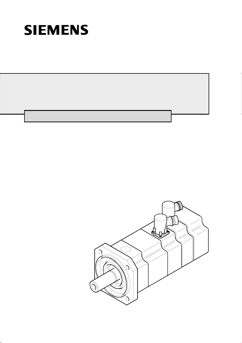
Three-phase servomotors
1FK7 02. - 1FK7 10.
Instructions Edition 11 / 2001
Drehstrom-Servomotoren
Servomoteurs triphasés
Servomotores trifásicos
Servomotori trifasi
Trefas servomotorer
610.40 700.21
Page 3

ENGLISH
CONTENTS
ENGLISH . . . . . . . . . . . . . . . . . . . . . . . . . . . . . . . . . . . . . . . . . . . . . . . . . . . . . . 8
1 General safety instructions . . . . . . . . . . . . . . . . . . . . . . . . . . . . . . . . . . . . . . 10
2 Product information . . . . . . . . . . . . . . . . . . . . . . . . . . . . . . . . . . . . . . . . . . . . 10
2.1 Product description . . . . . . . . . . . . . . . . . . . . . . . . . . . . . . . . . . . . . . . . 10
2.2 Scope of delivery. . . . . . . . . . . . . . . . . . . . . . . . . . . . . . . . . . . . . . . . . . 11
3 Technical data. . . . . . . . . . . . . . . . . . . . . . . . . . . . . . . . . . . . . . . . . . . . . . . . . 11
3.1 Rating plate . . . . . . . . . . . . . . . . . . . . . . . . . . . . . . . . . . . . . . . . . . . . . . 11
3.2 Features . . . . . . . . . . . . . . . . . . . . . . . . . . . . . . . . . . . . . . . . . . . . . . . . 12
4 Installation, Assembly . . . . . . . . . . . . . . . . . . . . . . . . . . . . . . . . . . . . . . . . . . 13
4.1 Transport, Storage . . . . . . . . . . . . . . . . . . . . . . . . . . . . . . . . . . . . . . . . 13
4.2 Installation . . . . . . . . . . . . . . . . . . . . . . . . . . . . . . . . . . . . . . . . . . . . . . . 14
5 Electrical connections . . . . . . . . . . . . . . . . . . . . . . . . . . . . . . . . . . . . . . . . . . 15
5.1 Important instructions . . . . . . . . . . . . . . . . . . . . . . . . . . . . . . . . . . . . . . 15
5.2 Plug design . . . . . . . . . . . . . . . . . . . . . . . . . . . . . . . . . . . . . . . . . . . . . . 17
6 Start-up . . . . . . . . . . . . . . . . . . . . . . . . . . . . . . . . . . . . . . . . . . . . . . . . . . . . . . 18
6.1 Checks before starting up . . . . . . . . . . . . . . . . . . . . . . . . . . . . . . . . . . . 18
6.2 Start-up . . . . . . . . . . . . . . . . . . . . . . . . . . . . . . . . . . . . . . . . . . . . . . . . . 19
7 Instructions in case of faults . . . . . . . . . . . . . . . . . . . . . . . . . . . . . . . . . . . . . 19
8 Inspection, maintenance, disposal . . . . . . . . . . . . . . . . . . . . . . . . . . . . . . . . 20
2 610.40 700.21 Siemens AG
Page 4

DEUTSCH
INHALT
DEUTSCH. . . . . . . . . . . . . . . . . . . . . . . . . . . . . . . . . . . . . . . . . . . . . . . . . . . . . 21
1 Allgemeine Sicherheitshinweise . . . . . . . . . . . . . . . . . . . . . . . . . . . . . . . . . . 23
2 Angaben zum Produkt . . . . . . . . . . . . . . . . . . . . . . . . . . . . . . . . . . . . . . . . . . 23
2.1 Produktbeschreibung. . . . . . . . . . . . . . . . . . . . . . . . . . . . . . . . . . . . . . . 23
2.2 Lieferumfang . . . . . . . . . . . . . . . . . . . . . . . . . . . . . . . . . . . . . . . . . . . . . 24
3 Technische Daten . . . . . . . . . . . . . . . . . . . . . . . . . . . . . . . . . . . . . . . . . . . . . . 24
3.1 Typenschild . . . . . . . . . . . . . . . . . . . . . . . . . . . . . . . . . . . . . . . . . . . . . . 24
3.2 Merkmale. . . . . . . . . . . . . . . . . . . . . . . . . . . . . . . . . . . . . . . . . . . . . . . . 25
4 Aufstellung, Montage . . . . . . . . . . . . . . . . . . . . . . . . . . . . . . . . . . . . . . . . . . . 26
4.1 Transport, Lagerung . . . . . . . . . . . . . . . . . . . . . . . . . . . . . . . . . . . . . . . 26
4.2 Aufstellung. . . . . . . . . . . . . . . . . . . . . . . . . . . . . . . . . . . . . . . . . . . . . . . 27
5 Elektrischer Anschluss . . . . . . . . . . . . . . . . . . . . . . . . . . . . . . . . . . . . . . . . . 28
5.1 Wichtige Hinweise . . . . . . . . . . . . . . . . . . . . . . . . . . . . . . . . . . . . . . . . . 28
5.2 Steckerausführung. . . . . . . . . . . . . . . . . . . . . . . . . . . . . . . . . . . . . . . . . 30
6 Inbetriebnahme . . . . . . . . . . . . . . . . . . . . . . . . . . . . . . . . . . . . . . . . . . . . . . . . 31
6.1 Prüfungen vor Inbetriebnahme . . . . . . . . . . . . . . . . . . . . . . . . . . . . . . . 31
6.2 Inbetriebnahme . . . . . . . . . . . . . . . . . . . . . . . . . . . . . . . . . . . . . . . . . . . 32
7 Hinweise bei Störungen . . . . . . . . . . . . . . . . . . . . . . . . . . . . . . . . . . . . . . . . . 32
8 Inspektion, Wartung, Entsorgung . . . . . . . . . . . . . . . . . . . . . . . . . . . . . . . . . 33
Siemens AG 610.40 700.21
3
Page 5

FRANÇAIS
SOMMAIRE
FRANÇAIS . . . . . . . . . . . . . . . . . . . . . . . . . . . . . . . . . . . . . . . . . . . . . . . . . . . . 34
1 Consignes générales de sécurité . . . . . . . . . . . . . . . . . . . . . . . . . . . . . . . . . 36
2 Indications relatives au produit. . . . . . . . . . . . . . . . . . . . . . . . . . . . . . . . . . . 36
2.1 Description du produit . . . . . . . . . . . . . . . . . . . . . . . . . . . . . . . . . . . . . . 36
2.2 Equipements fournis . . . . . . . . . . . . . . . . . . . . . . . . . . . . . . . . . . . . . . . 37
3 Caractéristiques techniques . . . . . . . . . . . . . . . . . . . . . . . . . . . . . . . . . . . . . 37
3.1 Plaque signalétique . . . . . . . . . . . . . . . . . . . . . . . . . . . . . . . . . . . . . . . . 37
3.2 Caractéristiques . . . . . . . . . . . . . . . . . . . . . . . . . . . . . . . . . . . . . . . . . . 38
4 Installation, montage . . . . . . . . . . . . . . . . . . . . . . . . . . . . . . . . . . . . . . . . . . . 39
4.1 Transport, positionnement. . . . . . . . . . . . . . . . . . . . . . . . . . . . . . . . . . . 39
4.2 Installation . . . . . . . . . . . . . . . . . . . . . . . . . . . . . . . . . . . . . . . . . . . . . . . 40
5 Raccordement électrique. . . . . . . . . . . . . . . . . . . . . . . . . . . . . . . . . . . . . . . . 41
5.1 Consignes importantes . . . . . . . . . . . . . . . . . . . . . . . . . . . . . . . . . . . . . 41
5.2 Modèle de prise. . . . . . . . . . . . . . . . . . . . . . . . . . . . . . . . . . . . . . . . . . . 43
6 Mise en service . . . . . . . . . . . . . . . . . . . . . . . . . . . . . . . . . . . . . . . . . . . . . . . . 44
6.1 Vérifications avant la mise en service. . . . . . . . . . . . . . . . . . . . . . . . . . 44
6.2 Mise en service . . . . . . . . . . . . . . . . . . . . . . . . . . . . . . . . . . . . . . . . . . . 45
7 Remarques en cas de dérangement . . . . . . . . . . . . . . . . . . . . . . . . . . . . . . . 45
8 Inspection, entretien, élimination . . . . . . . . . . . . . . . . . . . . . . . . . . . . . . . . . 46
4 610.40 700.21 Siemens AG
Page 6

ESPAÑOL
ÍNDICE
ESPAÑOL. . . . . . . . . . . . . . . . . . . . . . . . . . . . . . . . . . . . . . . . . . . . . . . . . . . . . 47
1 Indicaciones generales de seguridad . . . . . . . . . . . . . . . . . . . . . . . . . . . . . . 49
2 Datos respecto al producto . . . . . . . . . . . . . . . . . . . . . . . . . . . . . . . . . . . . . . 49
2.1 Descripción del producto . . . . . . . . . . . . . . . . . . . . . . . . . . . . . . . . . . . . 49
2.2 Volumen de suministro . . . . . . . . . . . . . . . . . . . . . . . . . . . . . . . . . . . . . 50
3 Datos técnicos. . . . . . . . . . . . . . . . . . . . . . . . . . . . . . . . . . . . . . . . . . . . . . . . . 50
3.1 Placa de características. . . . . . . . . . . . . . . . . . . . . . . . . . . . . . . . . . . . . 50
3.2 Características. . . . . . . . . . . . . . . . . . . . . . . . . . . . . . . . . . . . . . . . . . . . 51
4 Instalación y montaje . . . . . . . . . . . . . . . . . . . . . . . . . . . . . . . . . . . . . . . . . . . 52
4.1 Transporte, almacenamiento. . . . . . . . . . . . . . . . . . . . . . . . . . . . . . . . . 52
4.2 Instalación . . . . . . . . . . . . . . . . . . . . . . . . . . . . . . . . . . . . . . . . . . . . . . . 53
5 Conexión eléctrica . . . . . . . . . . . . . . . . . . . . . . . . . . . . . . . . . . . . . . . . . . . . . 54
5.1 Indicaciones importantes. . . . . . . . . . . . . . . . . . . . . . . . . . . . . . . . . . . . 54
5.2 Conexiones . . . . . . . . . . . . . . . . . . . . . . . . . . . . . . . . . . . . . . . . . . . . . . 56
6 Puesta en servicio. . . . . . . . . . . . . . . . . . . . . . . . . . . . . . . . . . . . . . . . . . . . . . 57
6.1 Comprobaciones antes de la puesta en servicio. . . . . . . . . . . . . . . . . . 57
6.2 Puesta en servicio . . . . . . . . . . . . . . . . . . . . . . . . . . . . . . . . . . . . . . . . . 58
7 Indicaciones en caso de avería . . . . . . . . . . . . . . . . . . . . . . . . . . . . . . . . . . . 58
8 Inspección, mantenimiento, eliminación de residuos. . . . . . . . . . . . . . . . . 59
Siemens AG 610.40 700.21
5
Page 7

ITALIANO
INDICE
ITALIANO. . . . . . . . . . . . . . . . . . . . . . . . . . . . . . . . . . . . . . . . . . . . . . . . . . . . . 60
1 Avvertenze generiche di sicurezza . . . . . . . . . . . . . . . . . . . . . . . . . . . . . . . . 62
2 Dati sul prodotto. . . . . . . . . . . . . . . . . . . . . . . . . . . . . . . . . . . . . . . . . . . . . . . 62
2.1 Descrizione del prodotto . . . . . . . . . . . . . . . . . . . . . . . . . . . . . . . . . . . . 62
2.2 Fornitura . . . . . . . . . . . . . . . . . . . . . . . . . . . . . . . . . . . . . . . . . . . . . . . . 63
3 Caratteristiche tecniche. . . . . . . . . . . . . . . . . . . . . . . . . . . . . . . . . . . . . . . . . 63
3.1 Targhetta. . . . . . . . . . . . . . . . . . . . . . . . . . . . . . . . . . . . . . . . . . . . . . . . 63
3.2 Caratteristiche . . . . . . . . . . . . . . . . . . . . . . . . . . . . . . . . . . . . . . . . . . . . 64
4 Installazione, montaggio . . . . . . . . . . . . . . . . . . . . . . . . . . . . . . . . . . . . . . . . 65
4.1 Trasporto, stoccaggio . . . . . . . . . . . . . . . . . . . . . . . . . . . . . . . . . . . . . . 65
4.2 Installazione . . . . . . . . . . . . . . . . . . . . . . . . . . . . . . . . . . . . . . . . . . . . . 66
5 Collegamento elettrico. . . . . . . . . . . . . . . . . . . . . . . . . . . . . . . . . . . . . . . . . . 67
5.1 Note importanti . . . . . . . . . . . . . . . . . . . . . . . . . . . . . . . . . . . . . . . . . . . 67
5.2 Tipo di connettore . . . . . . . . . . . . . . . . . . . . . . . . . . . . . . . . . . . . . . . . . 69
6 Messa in funzione. . . . . . . . . . . . . . . . . . . . . . . . . . . . . . . . . . . . . . . . . . . . . . 70
6.1 Verifica prima della messa in funzione . . . . . . . . . . . . . . . . . . . . . . . . . 70
6.2 Messa in funzione . . . . . . . . . . . . . . . . . . . . . . . . . . . . . . . . . . . . . . . . . 71
7 Istruzioni in caso di guasto . . . . . . . . . . . . . . . . . . . . . . . . . . . . . . . . . . . . . . 71
8 Ispezione, manutenzione, smaltimento . . . . . . . . . . . . . . . . . . . . . . . . . . . . 72
6 610.40 700.21 Siemens AG
Page 8

SVENSKA
INNEHÅLL
SVENSKA. . . . . . . . . . . . . . . . . . . . . . . . . . . . . . . . . . . . . . . . . . . . . . . . . . . . . 73
1 Allmän säkerhetsinformation. . . . . . . . . . . . . . . . . . . . . . . . . . . . . . . . . . . . . 75
2 Uppgifter om produkten. . . . . . . . . . . . . . . . . . . . . . . . . . . . . . . . . . . . . . . . . 75
2.1 Produktbeskrivning . . . . . . . . . . . . . . . . . . . . . . . . . . . . . . . . . . . . . . . . 75
2.2 Leveransens omfattning . . . . . . . . . . . . . . . . . . . . . . . . . . . . . . . . . . . . 76
3 Tekniska data . . . . . . . . . . . . . . . . . . . . . . . . . . . . . . . . . . . . . . . . . . . . . . . . . 76
3.1 Typskylt . . . . . . . . . . . . . . . . . . . . . . . . . . . . . . . . . . . . . . . . . . . . . . . . . 76
3.2 Kännetecken . . . . . . . . . . . . . . . . . . . . . . . . . . . . . . . . . . . . . . . . . . . . . 77
4 Uppställning, montering. . . . . . . . . . . . . . . . . . . . . . . . . . . . . . . . . . . . . . . . . 78
4.1 Transport, lagring. . . . . . . . . . . . . . . . . . . . . . . . . . . . . . . . . . . . . . . . . . 78
4.2 Uppställning. . . . . . . . . . . . . . . . . . . . . . . . . . . . . . . . . . . . . . . . . . . . . . 79
5 Elektrisk anslutning . . . . . . . . . . . . . . . . . . . . . . . . . . . . . . . . . . . . . . . . . . . . 80
5.1 Viktig information. . . . . . . . . . . . . . . . . . . . . . . . . . . . . . . . . . . . . . . . . . 80
5.2 Kontaktutförande . . . . . . . . . . . . . . . . . . . . . . . . . . . . . . . . . . . . . . . . . . 82
6 Driftsättning. . . . . . . . . . . . . . . . . . . . . . . . . . . . . . . . . . . . . . . . . . . . . . . . . . . 83
6.1 Kontroller innan driftsättning . . . . . . . . . . . . . . . . . . . . . . . . . . . . . . . . . 83
6.2 Driftsättning . . . . . . . . . . . . . . . . . . . . . . . . . . . . . . . . . . . . . . . . . . . . . . 83
7 Information vid störningar . . . . . . . . . . . . . . . . . . . . . . . . . . . . . . . . . . . . . . . 84
8 Inspektion, underhåll, avfallshantering . . . . . . . . . . . . . . . . . . . . . . . . . . . . 85
Siemens AG 610.40 700.21
7
Page 9
ENGLISH
This manual contains notes which you should observe to ensure your own personal
safety, as well to protect the product and connected equipment. These notices are
highlighted in the manual by a warning triangle and are marked as follows to the level of
danger. They are shown as follows according to the degree of danger involved.
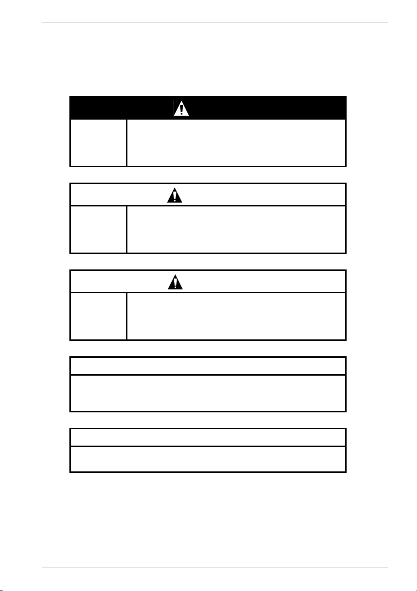
DANGER!
indicates an imminently hazardous situation which, if
Pictogram
not avoided by the appropriate precautionary
measures, will result in death, serious injury or
substantial material damage.
WARNING
indicates an imminently hazardous situation which, if
Pictogram
not avoided by the appropriate precautionary
measures, could result in death, serious injury or
substantial material damage.
CAUTION
Pictogram
used with the safety alert symbol indicates a
potentially hazardous situation which, if not avoided,
may result in minor or moderate injury.
CAUTION
used without the safety alert symbol indicates a potentially
hazardous situation which, if not avoided, may result in damage to
property.
NOTICE
indicates a potential situation which, if not avoided, may result in an
undesirable result or state.
8 610.40 700.21 Siemens AG
Page 10

ENGLISH
Qualified Personnel
The device/system may only be set up and operated in conjunction with this manual. Only
qualified personnel should be allowed to install and work on the this equipment. Qualified
persons are defined as persons who are authorized to commission, to ground, and to bag
circuits, equipment, and systems in accordance with established safety practices and
standards.
Intended Usage
Please note the following:
This device and its components may only be used for the applications described in the
catalog or technical description, and only in connection with devices or components from
other manufacturers which have been approved or recommended by Siemens.
This product can only function correctly and safely if it is transported, stored, set up, and
installed correctly, and operated and maintained as recommended.
Disclaimer of Liability
We have checked the contents of this manual. Since deviations cannot be precluded
entirely, we cannot guarantee full agreement. However, the data in the manual are
reviewed regularly and any necessary corrections included in subsequent editions.
Suggestions for improvement are welcomed.
© Copyright Siemens AG 2001. All rights reserved
The reproduction, transmission or use of this document or its contents is not permitted
without express written authority. Offenders will be liable for damages.
All rights, including rights created by patent grant or registration of a utility model or
design, are reserved.
Siemens AG
Bereich Automatisierungs- und Antriebstechnik
Geschäftsgebiet Motion Control Systeme (MC)
D-97615 Bad Neustadt an der Saale
Siemens AG 610.40 700.21
9
Page 11

ENGLISH
1 General safety instructions
The servomotors correspond to the harmonized standards of the EN 60034 (VDE 0530)
series EN 60034-1, EN 60034-6, EN 60034-9 and EN 60204-1.
The three-phase servomotors 1FK6 conform to 73/23/EEC Low Voltage Directive.
Standard motors conform to UL regulations. The rating plates of these motors are marked
with UR.
Ensure that your end product conforms to all currently valid legal requirements.
Follow the compulsory national, local and installation-specific regulations.
Three-phase servomotors are exclusively intended for fitting in another machine or
machines.
These motors must not be brought into use until it has been established that the end
product conforms to the currently valid directives.
The operating manual applies in conjunction with the SIEMENS project planning guide
"Three-Phase Servomotors“, order no. 6SN1197-0AC20-0AP.
All safety instructions must be observed during the transport, storage, assembly,
disassembly and operation of the servomotors!
Failure to observe the instructions can lead to serious personal injuries or property damage.
The motors’ rotors contain permanent magnets with high magnetic flux densities which exert
strong attractive forces on ferromagnetic bodies.
People fitted with a heart pacemaker are at risk in the vicinity of a disassembled rotor. Data
stored on electronic data media may be destroyed.
It is forbidden to use the motors in areas at risk of explosion, unless expressly stated.
Thermal hazards
The surface temperatures of the motors can reach up to 140 °C (284 °F).
Do not touch hot surfaces!
Temperature-sensitive components (electric lines, electronic components) must not touch
hot surfaces.
Overheating in the motors may destroy the windings and bearings, and demagnetize the
permanent magnets.
Only operate the motors with effective temperature control.
Intended use
Usage for the intended purpose includes observing all the specifications in the operating
manual and the project planning guide "Three-Phase Servomotors“.
2 Product information
2.1 Product description
Motors of 1FK7 series are permanent magnet excited, three-phase synchronous motors
(three-phase servomotors) for operating with motor-controlled indirect a.c. converters
according to the sinusoidal current principle.
The motors are intended for driving and positioning machine tools, production machines,
robots and handling devices.
10 610.40 700.21 Siemens AG
Page 12
ENGLISH
2.2 Scope of delivery
The drive systems are arranged individually. Immediately upon receipt of delivery, check
whether the scope of delivery corresponds with the consignment notes. SIEMENS cannot
accept any liability for any shortages or deficiencies reported at a later date.
Complaint instructions:
- Report detectable transport damage immediately to the carrier.
- Report detectable defects / incomplete delivery immediately to the responsible
SIEMENS representative.
The operating manual is part of the scope of delivery and shall therefore be kept in an
accessible place.
As the delivery includes a separate type plate, the motor data must also be kept on or near
the machine or system.
3 Technical data
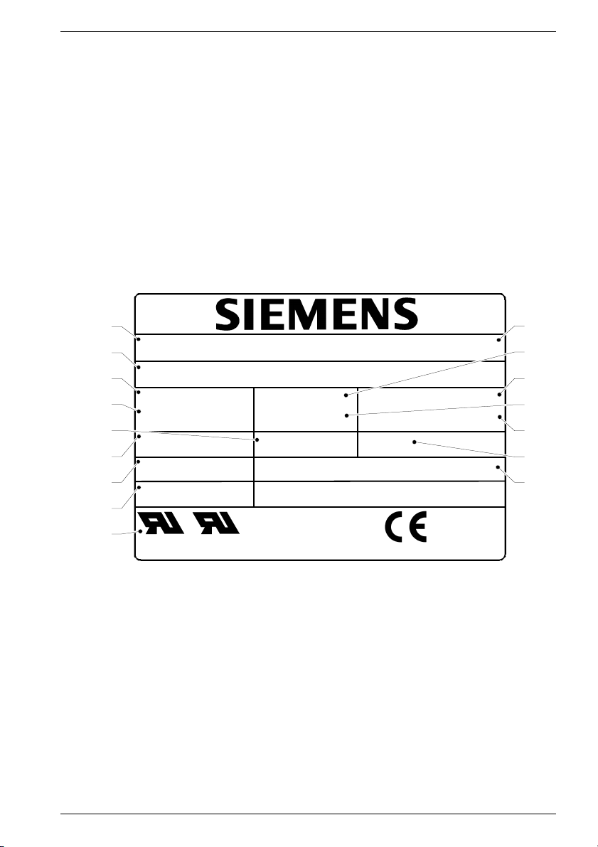
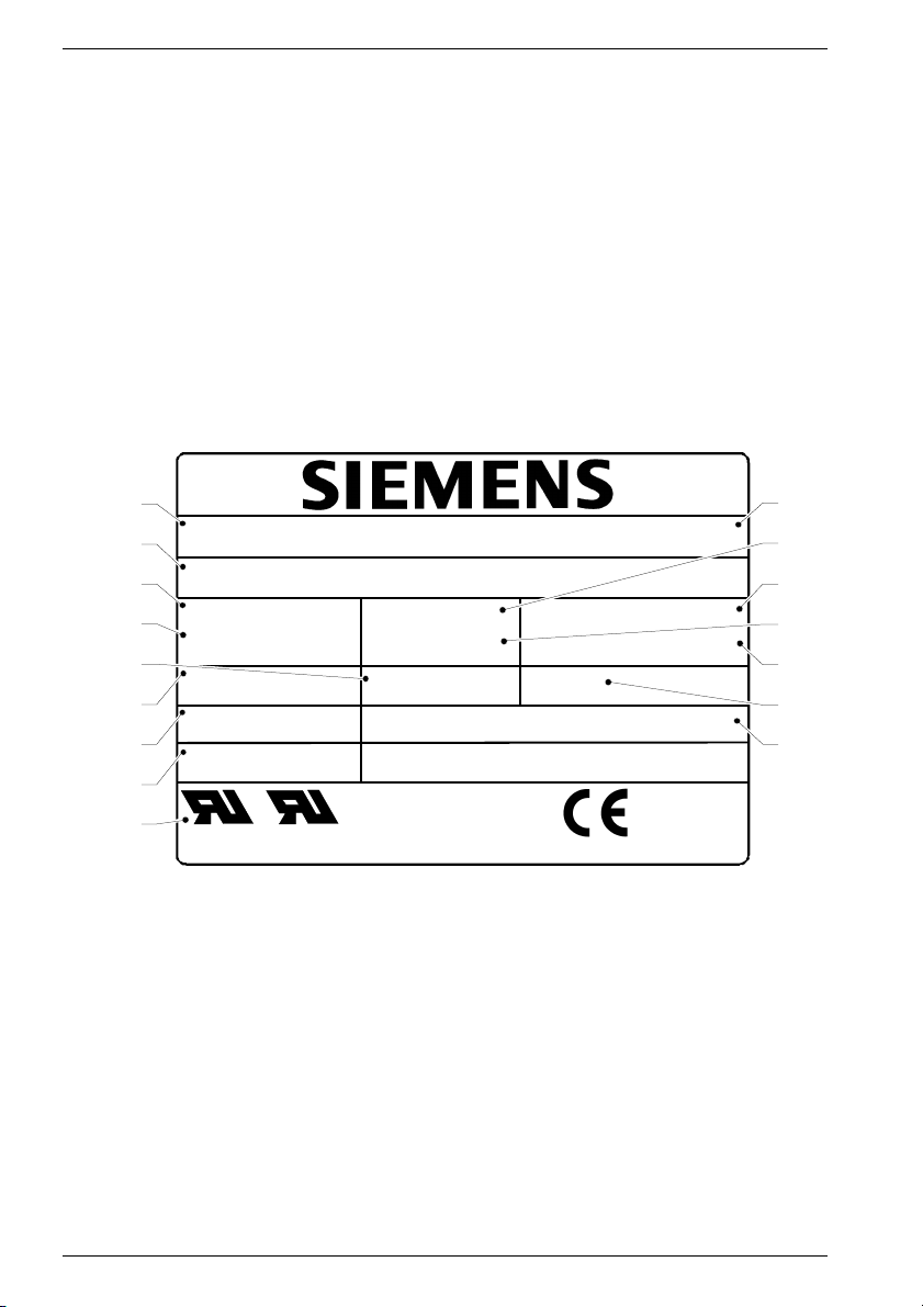
3.1 Rating plate
1
3~ Servomotor
2
No.YF: PN 184583 01 001
3
11 Nm IO 8,0 A n
M
4
5
O
7,3 Nm IN 5,6 A nN 3000 /min
M
N
Th.Cl. F U
6
1FK7063-5AF71-1AB3
6600 /min
max
263 V IP 64
IN
Encoder B01 Brake EBD 0.8BK / 24 V- / 19 W
7
Rev. No.: 000
8
9
EN 60034
Made in Germany
Fig. 1 Rating plate
1 Motor type: three-phase servomotor 10 SIEMENS motor type/ designation
2 IID No., production number 11 Zero-speed current I
3 Zero speed continuous torque M
4 Rated torque M
5 Induced voltage U
6 Temperature class 15 Degree of protection
7 Encoder type code 16 Holding brake data:
8 Version Type, voltage, power consumption
9 Standards and regulations
[Nm] 13 Rated current IN [A]
N
[V] 14 Rated speed nN [rpm]
IN
[Nm] 12 Maximum speed n
0
max
[A]
0
[rpm]
10
11
12
13
14
15
16
Siemens AG 610.40 700.21
11
Page 13

ENGLISH
3.2 Features
Types of construction IM B5 (IM V1, IM V3)
(EN 60034-7)
Degree of protection IP64
(EN 60034-5)
Cooling Self-cooling
(EN 60034-6)
A-grade sound intensity level
(EN 60034-9)
for speed range up to 3,000 rpm
1FK7 02., 1FK7 03., 1FK7 04. approx. 55 dB(A)
1FK7 06. approx. 65 dB(A)
1FK7 08., 1FK7 10. approx. 70 dB(A)
Thermal motor protection Temperature sensor KTY84
(EN 60034-11) in the stator winding
Shaft end cylindrical; without keyway,
(DIN 748-3; IEC 60072-1) Tolerance range k6
true running, coaxiality, axial run-out deviation Tolerance N
(DIN 42955; IEC 60072-1)
Vibration severity Grade N
(EN 60034-14)
Bearing Rolling contact bearing with permanent
Service life of bearing 20000 h (guideline)
Winding insulation Temperature class F
(EN 60034-1)
Ambient temperatures -15 °C to +40 °C (5 °F to 104 °F)
Installation altitude up to 1000 m a.s.l,
(EN 60034-1) 2000 m conversion factor 0,94
Magnetic material Rare-earth material
Electrical connections Revolving plug for output and
Encoder system fitted encoder
Additional technical parameters, dimensional sheets according to project planning guide
"Three-Phase Servomotors“, order no. 6SN1197-0AC20-0AP.
Options/expansions
Low inertia series HD (High Dynamic)
Type of protection IP 65; additional drive end flange IP67
(EN 60034-5)
grease lubrication (lifetime lubrication)
fixed bearing on non-drive end
otherwise the rated data are reduced
to 50 °C conversion factor 0,92
to 60 °C conversion factor 0,82
2500 m conversion factor 0,9
encoder signals
- speed recording
- recording the rotor position
- indirect positional recording
12 610.40 700.21 Siemens AG
Page 14
ENGLISH
Fitted/mounted elements - closed current holding brake
(DIN VDE 0580)
Supply voltage 24 V DC ±10%
- planetary gearing
Encoder system - incremental encoder sin/cos 1 V
- absolute value encoder EnDat
- simple, absolute value encoder
- resolver
Shaft end cylindrical with keyway and
(DIN 748-3; IEC 60072-1) feather key; Tolerance range k6
(balancing with half feather key)
You will find more technical details, e.g. motor dimensions, in the catalogs NC 60 and
DA 65.3.
4 Installation, Assembly
4.1 Transport, Storage
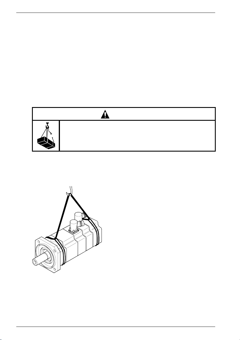
WARNING
Danger during lifting and transporting procedures!
Improper handling, unsuitable or defective devices, tools etc. can
cause injuries and/or property damage.
Lifting devices, ground conveyors and lifting tackle must correspond
to the valid regulations.
PP
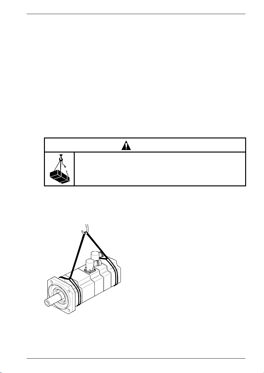
Use suitable load suspension devices for transport and assembly.
Use lifting eyes for transporting the motors where these are provided by the manufacturer.
Lifting tackle as per 98/37/EU Directive for Machines, Appendix I.
The motors weigh up to 50 kg. For exact details, please refer to the catalog or dimensional
sheet.
Fig. 2 Lift and transport with suspension bands
Observe the transport regulations applying in the country/countries concerned.
Store in a dry, low-dust and low-vibration place (v
Siemens AG 610.40 700.21
< 0,2 mms-1)
eff
13
Page 15
4.2 Installation
ENGLISH
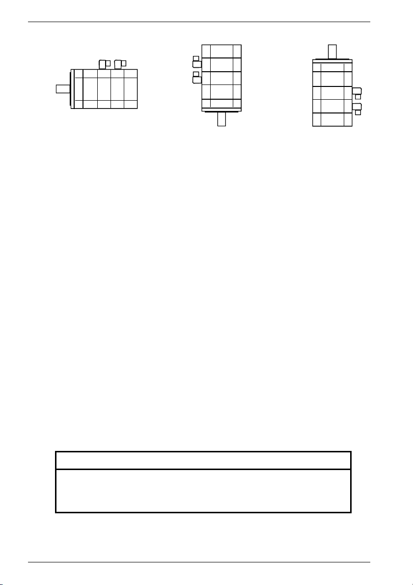
IM B 5 IM V 1
Fig. 3 Types of construction
- Take note of and observe the information on the rating plate and warning and informative
notices on the motor.
- Observe the permitted transverse and axial forces (see project planning instructions).
Axial forces are not permitted on motors with an integrated brake.
- Check for compliance with the conditions (e.g. temperature, site altitude) at the assembly
site (see Section 3.2).
- It is forbidden to use them in areas at risk of explosion.
- Remove all anti-corrosion agents from the shaft end (use commercially available
solvent).
- Ensure that waste heat is adequately dissipated.
It is recommended to maintain a clearance of 100 mm from adjacent parts on at least
three sides.
- Tighten the flanges equally, avoid distortions when tightening the fixing screws. Use
hexagon socket head cap screws, strength class at least 8.8.
- In the case of a vertical installation with the shaft end at the top, ensure that no fluid
penetrates into the upper bearing.
- Lifting eye-bolts which have been screwed in may be removed after the motor has been
installed.
- Turn the output elements by hand. If grinding noises occur, eliminate the cause or
contact the manufacturer.
IM V 3
Vibrations, balancing
Motors with a keyway are balanced by the manufacturer with a half feather key.
The site vibration response of the system is determined by the output elements, the
mounting conditions, the alignment, the installation and the effects of external vibrations.
This may cause a modification of the motor vibration values.
The vibrations immited in the fitted state must not exceed acceleration of 5 g.
Output elements
NOTICE
Do not strike the shaft or bearings of the motors.
Do not exceed the permissible axial and radial forces on the shaft end stated
in the configuration specification.
Axial forces are not permitted on motors with an integrated brake.
14 610.40 700.21 Siemens AG
Page 16
ENGLISH
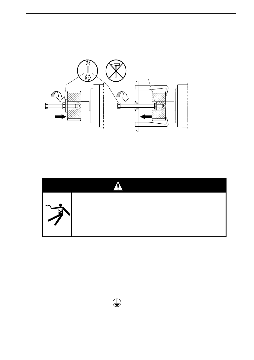
Suitable devices should always be used to push on or pull off the output elements (e.g. the
coupler, gear wheel, belt pulley, Fig. 4).
- Use the tapped hole in the shaft end.
- Heat up the output elements if necessary.
- Use a shim to protect the centering in the shaft end when pulling output elements off.
- If necessary, fully balance the motor with the output elements according to ISO1940
A
Fig. 4 Pulling off and putting on output elements.
A Shim (protects the centering in the shaft end)
5 Electrical connections
5.1 Important instructions
DANGER!
Electric shock hazard!
When the rotor is rotating, the motor terminals carry a voltage of
up to approx. 300 V.
Stop the motor before commencing any electrical work.
Only use trained, qualified personnel for assembly work on the
converters and plugs.
Observe the regulations for working in electrotechnical plants.
Safety rules for working in electrical installations as per
EN 50110-1 (DIN VDE 0105-100):
- Work always with the equipment electrically dead.
- Isolate from electrical supply.
- Secure against switching on again.
- Check electrical deadness.
- Earth and short-circuit.
- Cover or cordon off adjacent parts which are electrically live.
- Release for work.
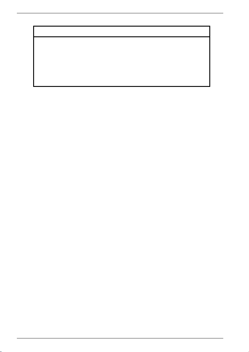
- Connect the PE conductor to
Siemens AG 610.40 700.21
15
Page 17
ENGLISH
Assembly requirements
CAUTION
Warning of motor damage!
Connecting the motor directly to a three-phase system will destroy it.
Motors may only be driven with configured converters!
Ensure that the phase sequence is correct.
Encoder systems and temperature sensor contain electrostatically
endangered components (EEC).
Do not touch the connections with your hands or tools which could be
electrostatically charged!
Pre-assembled cables from SIEMENS are recommended (not included in scope of delivery).
These cables reduce the assembly time and increase operational safety.
- Proper installation is the responsibility of the manufacturer of the system / machine.
- Observe the data on the type plate (Section 3.1)and the information in the wiring
diagrams (Fig. 5).
- Connecting leads must be suitable for the type of application and for the anticipated
currents and voltages.
- If the motor is supplied by means of converters, high-frequency current and voltage
harmonics in the motor supply leads can cause electromagnetic interference to be
emitted.
Use shielded power and signal lines.
Observe the EMC instructions of the converter manufacturer.
- The inside of the plug must be kept clean and free from cable residues and moisture.
- Avoid protruding wire ends.
- Check the seals and sealing surfaces of plug to ensure that the degree of protection is
maintained.
- The connecting leads are to be equipped with the strain relief device and the devices
which protect against rotation and transverse forces, and must be prevented from
kinking. The plugs must not be subjected to continuous forces.
- The coding slot on the plug connector must be aligned when inserted into the female
connector in each case, and the union nut tightened up to the stop by hand.
The protective function with a fitted temperature sensor is inadequate for high thermal loads,
e.g. overload with the motor at a standstill. Additional protective measures are to be provided
for such cases, e.g. a thermal overcurrent relay.
16 610.40 700.21 Siemens AG
Page 18
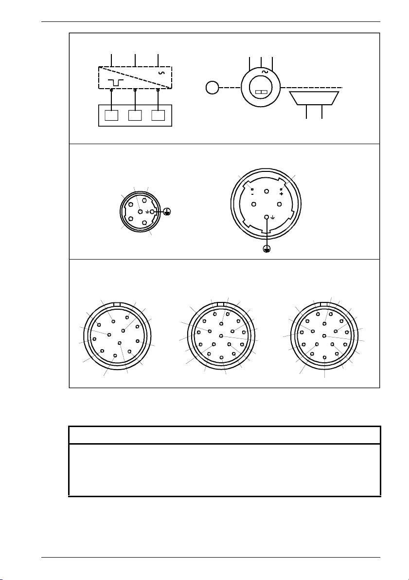
Supply
L1 L2 L3
ENGLISH
UVW
3
U2
UV
Motor
Power connections
1FK7 02. - 1FK7 100
U
BR2
Connector size 1 Connector size 1,5
Signal connections
Resolver
- Temp
S2
8
1
10
2
3
not
connected
9
12
11
5
4
S1
R1
S4
not
connected
Fig. 5 Circuits
V2
W
1
6
5
+ Temp
7
6
3
W2
W
V
2
4
BR
S3
R3
not
conn.
not
connected
Encoder
GNYE
Incremental Encoder
sin/cos 1 V
P-Encoder
(5V)
5V
Sense
- Temp
+ Temp
0V
Sense
B +
10
9
16
8
7
M-Encoder
(0V)
1FK7 101 / 1FK7 103
BR2
WU
GNYE
PP
B -
A +
1
11
2
12
13
3
14
E
4
15
6
5
C +
C -
3
Motor
A -
R -
not
conn.
D -
D +
M
BR
(+)
BR
V
Absolute Encoder
Simple Absolute Encoder
P-Encoder
5V Sense
R +
- Temp
+ Temp
0V Sense
10
9
8
M-Encoder
BR2
(-)
B +
11
12
16
17
15
6
7
not
connected
B -
1
13
14
5
Brake
A +
A -
2
3
4
- Clock
+ Clock
- Data
+ Data
not
conn.
not
conn.
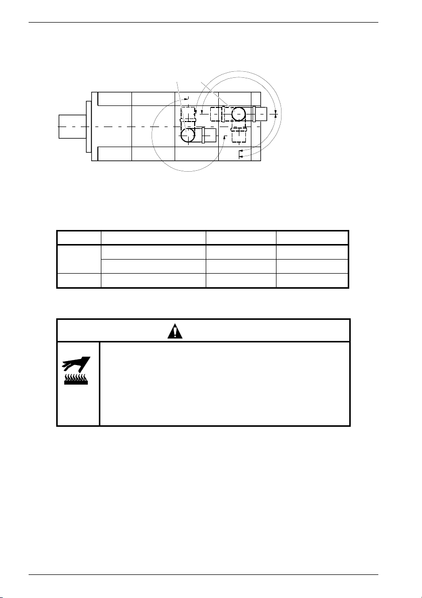
5.2 Plug design
NOTICE
Improper change of the plug output direction leads to damage to the connecting
cables.
Do not exceed the permissible twisting moments as per Fig. 6.
A maximum of ten changes to the plug output direction are permissible up to the
stop with the attached, matching, mating plug.
Power plug
1. Use plug size 1 or 1.5.
2. Assign the plugs according to figure Fig. 5 Connect the PE conductor.
3. Connect the brake via Fig. 5 the power plug.
Siemens AG 610.40 700.21
17
Page 19
ENGLISH
Signal plug for the encoder system and temperature sensor.
1. Use an appropriate plug.
2. Assign the plugs according to Fig. 5.
P Power plug S Signal plug
Fig. 6 Degree of rotation of plugs
Maximum permissible twisting moments M
Plug Motor Plug size M
P
SM
1FK7 02. - 1FK7 100 1 M
1FK7 101 / 1FK7 103 1.5 M
6Start-up
Thermal hazard from hot surfaces!
The surface temperatures of the motors can reach up to 140 °C
(284 °F).
Do not touch hot surfaces!
Protection must be provided against accidental contact if
necessary.
Temperature-sensitive components (electric lines, electronic
components) must not touch hot surfaces.
2
7
0
°
SP
max
180°
CAUTION
270°
9
°
0
max
= 12 Nm
max
= 20 Nm
max
= 12 Nm
max
6.1 Checks before starting up
Before starting up, ensure that
- all connections have been properly made, and the plug connectors are secured against
working loose.
- all motor protection devices are active,
- the drive is not blocked,
- no other possible sources of danger are present,
- the drive is undamaged (no damage from transport/storage),
- the feather keys in the shaft end (if present) are secured against being thrown out.
18 610.40 700.21 Siemens AG
Page 20
ENGLISH
6.2 Start-up
WARNING
Hazard from rotating rotor!
Protect the output elements against accidental contact!
Secure feather key (if present) against being thrown out.
Observe the start up and commissioning instructions for the converter (e.g. SIMODRIVE,
MASTERDRIVES MC).
NOTICE
The brake is designed for emergency stops (power cut, emergency stop).
It is not permitted to be used as a working brake.
After the motor has been switched off, it functions as a holding brake.
1. Release brake, in as far as this is necessary.
2. Check the brake function (open and close).
Apply 24 V DC ±10% to the pins BR, BR2 (Fig. 5), and ensure that the rotor is running
freely (no rubbing noises).
3. Check the mounting, seating and alignment of the motor.
4. Check the suitability and setting of the output elements for the intended conditions of
use, for example belt tension.
5. Check the power and signal plug connections.
6. Check the functional condition of the auxiliary devices present.
7. Check the protection against accidental contact with moving and live parts.
8. Bring the drive system into operation in accordance with the operating manual for the
converter or inverse rectifier.
9. Check that the maximum permissible speed n
details). The maximum permissible speed is the highest permissible, short-term
operating speed.
10. The fitted temperature sensor cannot cater for all possible faults (note the instructions
in the project planning guide).
is observed (see type plate for
max
7 Instructions in case of faults
In case of deviation from normal operation or faults, proceed first according to the following
list:
In this connection, please also refer to the relevant section of the operating manual for the
components of the entire drive system.
Do not disable the protective devices, even in trial operation.
Consult the manufacturer or the SIEMENS service center when necessary.
For start up, system motor converter: A&D Hotline +49 180 50 50 222
For motor / motor components: Contact in the works +49 174-3110669
Siemens AG 610.40 700.21 19
Page 21
ENGLISH
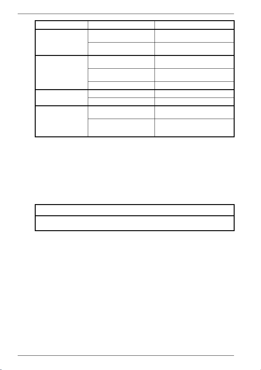
Fault Cause Remedy
Irregular running Inadequate screening of the
Vibrations Coupling elements or driven
Running noises Foreign bodies inside the motor Repair by the manufacturer
Motor overheats
(surface temperature
> 140 °C (284 °F))
Temperature monitoring
responds
motor or encoder cable.
Amplification of the drive controller too high
machine are badly balanced
Inadequate alignment of the drive
train
Fixing screws are loose Check and tighten screw connections
Bearing damage Repair by the manufacturer
Drive overloaded Check load (see type plate)
Heat dissipation impaired by
deposits
Check screening and grounding (see
Section 5.1)
Adjust controller (see converter operating manual)
Rebalance
Realign the machine set
Clean surface of drives.
Ensure that the cooling air can flow
freely in and out
8 Inspection, maintenance, disposal
Clean according to the degree of local contamination in order to ensure that the waste heat
is adequately dissipated.
As the operating conditions vary greatly, one can only cite general intervals for fault-free
operation.
Guidelines:
- Bearing service life 20,000 hours
- Radial shaft seals approx. 5,000 hours with oil lubrication.
NOTICE
The encoder system must be readjusted each time after the motor has been
disassembled.
Dispose of the motor in accordance with the national and local regulations in the standard
recycling process or return it to the manufacturer.
Dispose of the encoder electronics properly as electronic scrap.
20 610.40 700.21 Siemens AG
Page 22
DEUTSCH
Diese Betriebsanleitung enthält Hinweise, die Sie zu Ihrer persönlichen Sicherheit sowie
zur Vermeidung von Sachschäden beachten müssen. Die Hinweise zu Ihrer persönlichen
Sicherheit sind durch ein Warndreieck hervorgehoben, Hinweise zu alleinigen
Sachschäden stehen ohne Warndreieck. Je nach Gefährdungsgrad werden sie
folgendermaßen dargestellt:
GEFAHR
bedeutet, dass Tod, schwere Körperverletzung oder
Piktogramm
erheblicher Sachschaden eintreten werden, wenn die
entsprechenden Vorsichtsmaßnahmen nicht getroffen
werden.
WARNUNG
bedeutet, dass Tod, schwere Körperverletzung oder
Piktogramm
erheblicher Sachschaden eintreten können, wenn die
entsprechenden Vorsichtsmaßnahmen nicht getroffen
werden.
VORSICHT
Piktogramm
mit Warndreieck bedeutet, dass eine leichte
Körperverletzung eintreten kann, wenn die
entsprechenden Vorsichtsmaßnahmen nicht getroffen
werden.
VORSICHT
ohne Warndreieck bedeutet, dass ein Sachschaden eintreten kann,
wenn die entsprechenden Vorsichtsmaßnahmen nicht getroffen
werden.
ACHTUNG
bedeutet, dass ein unerwünschtes Ereignis oder Zustand eintreten
kann, wenn der entsprechende Hinweis nicht beachtet wird.
Siemens AG 610.40 700.21 21
Page 23

DEUTSCH
Qualifiziertes Personal
Inbetriebsetzung und Betrieb des Gerätes dürfen nur von qualifiziertem Personal
vorgenommen werden. Qualifiziertes Personal im Sinne der sicherheitstechnischen
Hinweise dieser Betriebsanleitung sind Personen, die die Berechtigung haben, Geräte,
Systeme und Stromkreise gemäß den Standards der Sicherheitstechnik in Betrieb zu
nehmen, zu erden und zu kennzeichnen.
Bestimmungsgemäßer Gebrauch
Beachten Sie folgendes:
Das Gerät darf nur für die im Katalog und in der Projektierungsanleitung vorgesehenen
Einsatzfälle und nur in Verbindung mit von Siemens empfohlenen bzw. zugelassenen
Fremdgeräten und -komponenten verwendet werden.
Der einwandfreie und sichere Betrieb des Produktes setzt sachgemäßen Transport,
sachgemäße Lagerung, Aufstellung und Montage sowie sorgfältige Bedienung und
Instandsetzung voraus.
Haftungsausschluss
Wir haben den Inhalt der Druckschrift geprüft. Dennoch können Abweichungen nicht
ausgeschlossen werden, so dass wir für die vollständige Übereinstimmung keine Gewähr
übernehmen. Die Angaben in dieser Druckschrift werden regelmäßig überprüft, und
notwendige Korrekturen sind in den nachfolgenden Auflagen enthalten. Für
Verbesserungsvorschläge sind wir dankbar.
© Copyright Siemens AG 2001. All rights reserved
Weitergabe sowie Vervielfältigung dieser Unterlage, Verwertung und Mitteilung ihres
Inhalts ist nicht gestattet, soweit nicht ausdrücklich zugestanden. Zuwiderhandlungen
verpflichten zum Schadenersatz.
Alle Rechte vorbehalten, insbesondere für den Fall der Patenterteilung oder
GM-Eintragung.
Siemens AG
Bereich Automatisierungs- und Antriebstechnik
Geschäftsgebiet Motion Control Systeme (MC)
D-97615 Bad Neustadt an der Saale
22 610.40 700.21 Siemens AG
Page 24

DEUTSCH
1 Allgemeine Sicherheitshinweise
Die Servomotoren entsprechen den harmonisierten Normen der Reihe
EN 60034-1, EN 60034-6, EN 60034-9 sowie EN 60204-1.
Für die Drehstrom-Servomotoren 1FK6 besteht Konformität mit
73/23/EWG Niederspannungsrichtlinie.
Standardmotoren entsprechen den UL-Vorschriften. Diese Motoren sind auf dem
Leistungsschild mit UR gekennzeichnet.
Sichern Sie für Ihr Endprodukt die Einhaltung aller bestehenden Rechtsvorschriften!
Beachten Sie die verbindlichen nationalen, örtlichen und anlagenspezifischen
Vorschriften!
Drehstrom-Servomotoren sind ausschließlich zum Einbau in (eine) andere Maschine(n)
bestimmt.
Die Inbetriebnahme der Motoren ist so lange untersagt, bis die Konformität des
Endprodukts mit den geltenden Richtlinien festgestellt ist.
Die Betriebsanleitung gilt in Verbindung mit der SIEMENS-Projektierungsanleitung
„Drehstrom-Servomotoren“, Best.-Nr. 6SN1197-0AC20-0AP0.
Für Transport, Lagerung, Montage, Demontage und Betrieb der Servomotoren müssen alle
Hinweise zur Sicherheit beachtet werden!
Das Nichteinhalten kann schwere Körperverletzungen oder Sachschäden bewirken.
Die Läufer der Motoren enthalten Permanentmagnete mit hohen magnetischen
Flussdichten und starken Anziehungskräften zu ferromagnetischen Körpern.
In der Nähe eines demontierten Läufers sind Personen mit Herzschrittmacher gefährdet.
Auf elektronischen Datenträgern gespeicherte Daten können zerstört werden.
Der Einsatz in explosionsgefährdeten Bereichen ist verboten, sofern nicht ausdrücklich
bestätigt.
Thermische Gefährdung
Die Oberflächentemperatur der Motoren kann bis 140 °C betragen.
Berühren Sie nicht heiße Oberflächen!
Temperaturempfindliche Bauteile (elektrische Leitungen, elektronische Bauteile) dürfen
nicht an heißen Oberflächen anliegen.
Überhitzung der Motoren kann Zerstörung der Wicklungen und Lager und
Entmagnetisierung der Permanentmagnete bewirken.
Betreiben Sie die Motoren nur mit wirksamer Temperaturkontrolle!
Bestimmungsgemäßer Gebrauch
Das Einhalten aller Vorgaben der Betriebsanleitung und der Projektierungsanleitung
„Drehstrom-Servomotoren“ ist Bestandteil der bestimmungsgemäßen Verwendung.
2 Angaben zum Produkt
2.1 Produktbeschreibung
Motoren der Baureihe 1FK7 sind permanentmagneterregte Drehstrom-Synchron-Motoren
(Drehstrom-Servomotoren) zum Betrieb mit motorgesteuerten Pulswechselrichtern nach
dem Sinusstromprinzip.
Die Motoren sind vorgesehen für Antrieb und Positionierung von Werkzeug- und
Produktionsmaschinen sowie Robotern und Handhabungsgeräten.
Siemens AG 610.40 700.21 23
Page 25
DEUTSCH
2.2 Lieferumfang
Die Antriebssysteme sind individuell zusammengestellt. Überprüfen Sie nach Erhalt der
Lieferung sofort, ob der Lieferumfang mit den Warenbegleitpapieren übereinstimmt. Für
nachträglich reklamierte Mängel übernimmt SIEMENS keine Gewährleistung.
Reklamieren Sie
- erkennbare Transportschäden sofort beim Anlieferer,
- erkennbare Mängel/ unvollständige Lieferung sofort bei der zuständigen
SIEMENS-Vertretung.
Die Betriebsanleitung ist Bestandteil des Lieferumfanges und somit zugänglich
aufzubewahren.
Das der Lieferung lose beigefügte Typenschild ist dafür vorgesehen, die Motordaten
zusätzlich an oder bei der Maschine oder Anlage aufzubewahren.
3 Technische Daten
3.1 Typenschild
1
3~ Servomotor
2
No.YF: PN 184583 01 001
3
11 Nm IO 8,0 A n
M
4
5
O
7,3 Nm IN 5,6 A nN 3000 /min
M
N
Th.Cl. F U
6
1FK7063-5AF71-1AB3
6600 /min
max
263 V IP 64
IN
Encoder B01 Brake EBD 0.8BK / 24 V- / 19 W
7
Rev. No.: 000
8
9
EN 60034
Made in Germany
Fig. 1 Typenschild
1 Motorart: Drehstrom-Servomotor 10 SIEMENS Motortyp/ Bezeichnung
2 Ident. Nr., Produktionsnummer 11 Stillstandsstrom I
3 Stillstandsdauerdrehmoment M
4 Bemessungsdrehmoment M
5 Induzierte Spannung U
6 Wärmeklasse 15 Schutzart
7 Kennzeichnung Gebertyp 16 Daten zur Haltebremse:
8 Versionsstand Typ, Spannung, Leistungsaufnahme
9 Normen und Vorschriften
IN
[Nm] 12 Maximaldrehzahl n
0
[Nm] 13 Bemessungsstrom IN [A]
N
[V] 14 Bemessungsdrehzahl nN [1/min]
[A]
0
[1/min]
max
10
11
12
13
14
15
16
24 610.40 700.21 Siemens AG
Page 26

DEUTSCH
3.2 Merkmale
Bauform IM B5 (IM V1, IM V3)
(EN 60034-7)
Schutzart IP64
(EN 60034-5)
Kühlung Selbstkühlung
(EN 60034-6)
A-bewerteter Schallleistungspegel
(EN 60034-9)
für Drehzahlbereich bis 3000 min
1FK7 02., 1FK7 03., 1FK7 04. ca. 55 dB(A)
1FK7 06. ca. 65 dB(A)
1FK7 08., 1FK7 10. ca. 70 dB(A)
Thermischer Motorschutz Temperatursensor KTY84
(EN 60034-11) in der Ständerwicklung
Wellenende Zylindrisch; ohne Passfedernut,
(DIN 748-3; IEC 60072-1) Toleranzfeld k6
Rundlauf, Koaxialität, Planlauf Toleranz N
(DIN 42955; IEC 60072-1)
Schwingstärke Stufe N
(EN 60034-14)
Lager Wälzlager mit Fettdauerschmierung
Lagergebrauchsdauer 20000 h (Richtwert)
Wicklungsisolation Wärmeklasse F
(EN 60034-1)
Umgebungstemperaturen -15 °C bis +40 °C (5 °F bis 104 °F)
Aufstellhöhe ≤ 1000 m über NN,
(EN 60034-1) 2000 m Leistung Faktor 0,94
Magnetmaterial Selten-Erd-Material
Elektrischer Anschluss drehbare Stecker für Leistung und
Gebersystem eingebauter Geber
Weitere technische Kennwerte, Maßblätter nach Projektierungsanleitung
„Drehstrom-Servomotoren“, Best.-Nr. 6SN1197-0AC20-0AP0.
Optionen/Erweiterungen
Baureihe geringer Trägheit HD (High Dynamic)
Schutzart IP 65; zusätzlich AS-Flansch IP67
(EN 60034-5)
Ein-/Anbauten - Ruhestromhaltebremse (DIN VDE 0580)
Siemens AG 610.40 700.21 25
-1
(Lebensdauerschmierung)
Festlager auf B-Seite
sonst Reduzierung der Nenndaten
bis 50 °C Leistung Faktor 0,92
bis 60 °C Leistung Faktor 0,82
2500 m Leistung Faktor 0,9
Gebersignale
- Erfassung der Drehzahl
- Erfassung der Rotorlage
- indirekte Lageerfassung
Anschlussspannung 24 V DC ±10%
Page 27
DEUTSCH
- Planetengetriebe
Gebersystem - Inkrementalgeber sin/cos 1 V
- Absolutwertgeber EnDat
- Einfach-Absolutwertgeber
- Resolver
Wellenende zylindrisch mit Passfedernut und
(DIN 748-3; IEC 60072-1) Passfeder; Toleranzfeld k6
(Wuchtung mit halber Passfeder)
Weitere technische Angaben, z.B. Motorabmessungen, finden Sie im Katalog NC 60 oder
DA 65.3.
4 Aufstellung, Montage
4.1 Transport, Lagerung
WARNUNG
Gefährdung bei Hebe- und Transportvorgängen!
Unsachgemäße Ausführung, ungeeignete oder schadhafte Geräte und
Hilfsmittel können Verletzungen und/oder Sachschäden bewirken.
Hubgeräte, Flurförderzeuge und Lastaufnahmemittel müssen den
Vorschriften entsprechen.
Für Transport und Montage geeignete Lastaufnahmemittel benutzen.
Hebeösen für den Transport der Motoren verwenden, wenn vom Hersteller vorgesehen.
Lastaufnahmemittel nach 98/37/EG Richtlinie für Maschinen, Anhang I.
Die Motoren haben eine Masse bis zu 50 kg. Genaue Angaben siehe Katalog bzw. Maßblatt.
PP
Fig. 2 Heben und Transportieren mit Schlaufenhebegurten
Beim Transport landesspezifische Vorschriften einhalten.
Die Lagerung erfolgt im trockenen, staub- und schwingungsarmen (v
Innenraum.
26 610.40 700.21 Siemens AG
< 0,2 mms-1)
eff
Page 28

4.2 Aufstellung
DEUTSCH
IM B 5 IM V 1
Fig. 3 Bauformen
- Angaben des Leistungsschildes, Warn- und Hinweisschilder am Motor beachten.
- Zulässige Quer- und Axialkräfte beachten (siehe Projektierungsanleitung).
Bei Motoren mit integrierter Bremse sind Axialkräfte nicht zulässig.
- Übereinstimmung mit den Bedingungen (z.B. Temperaturen, Aufstellhöhe) am
Montageort prüfen (siehe 3.2).
- Der Einsatz in explosionsgefährdeten Bereichen ist verboten.
- Wellenende gründlich von Korrosionsschutzmittel befreien (handelsübliche
Lösungsmittel verwenden).
- Ausreichende Abführung der Verlustwärme sichern.
Es wird empfohlen, an mindestens drei Seiten Abstände von 100 mm zu benachbarten
Teilen einzuhalten.
- Gleichmäßige Auflage der Flanschbefestigung beachten, Verspannungen beim
Anziehen der Befestigungsschrauben vermeiden. Zylinderschrauben mit
Innensechskant, Festigkeitsklasse mindestens 8.8 verwenden.
- Bei vertikaler Aufstellung mit Wellenende nach oben sicherstellen, dass keine Flüssigkeit
in das obere Lager eindringen kann.
- Eingeschraubte Hebeösen können nach dem Aufstellen entfernt werden.
- Abtriebselemente von Hand drehen. Bei möglichen Schleifgeräuschen die Ursache
beseitigen oder den Hersteller konsultieren.
IM V 3
Immitierte Schwingungen, Wuchtung
Motoren mit Passfedernut werden durch den Hersteller mit halber Passfeder ausgewuchtet.
Das Schwingverhalten des Systems am Einsatzort wird beeinflusst durch Abtriebselemente,
Anbauverhältnisse, Ausrichtung, Aufstellung und Fremdschwingungen. Damit können sich
die Schwingwerte des Motors ändern.
Die immitierten Schwingungen im eingebauten Zustand dürfen Beschleunigungen von 5 g
nicht überschreiten.
Abtriebselemente
ACHTUNG
Welle und Lager der Motoren nicht mit Schlägen belasten.
Zulässige Axial- und Radialkräfte auf das Wellende nach
Projektierungsvorschrift nicht überschreiten.
Bei Motoren mit integrierter Bremse sind Axialkräfte nicht zulässig.
Siemens AG 610.40 700.21 27
Page 29

DEUTSCH
Auf- und Abziehen von Abtriebselementen (z. B. Kupplung, Zahnrad, Riemenscheibe) nur
mit geeigneten Vorrichtungen ausführen (Fig. 4).
- Gewindebohrung im Wellenende benutzen.
- Abtriebselemente bei Bedarf erwärmen.
- Beim Abziehen Zwischenscheibe zum Schutz der Zentrierung im Wellenende benutzen.
- Bei Bedarf Motor mit Abtriebselementen nach ISO1940 komplett auswuchten.
A
Fig. 4 Auf- und Abziehen von Abtriebselementen
Zwischenscheibe (Schutz der Zentrierung im Wellenende)
A
5 Elektrischer Anschluss
5.1 Wichtige Hinweise
GEFAHR
Stromschlaggefahr!
Bei rotierendem Läufer liegt an den Motorklemmen Spannung von
ca. 300 V an.
Alle Elektroarbeiten nur bei Motorstillstand ausführen!
Für Montagearbeiten an Umrichter und Stecker nur qualifizierte
Fachkräfte einsetzen!
Vorschriften für Arbeiten in elektrotechnischen Anlagen einhalten!
Sicherheitsregeln für das Arbeiten in elektrischen Anlagen nach
EN 50110-1 (DIN VDE 0105-100):
- Nur im spannungslosen Zustand arbeiten.
- Freischalten.
- Gegen Wiedereinschalten sichern.
- Spannungsfreiheit feststellen.
- Erden und Kurzschließen.
- Benachbarte, unter Spannung stehende Teile abdecken oder abschranken.
- Freigabe zur Arbeit.
- Schutzleiter an anschließen!
28 610.40 700.21 Siemens AG
Page 30

DEUTSCH
Montageanforderungen
VORSICHT
Warnung vor Motorschäden!
Der direkte Anschluss an das Drehstromnetz führt zur Zerstörung des Motors.
Motoren nur mit den projektierten Umrichtern betreiben!
Richtige Phasenfolge beachten!
Gebersysteme und Temperatursensor sind elektrostatisch gefährdete
Bauteile (EGB).
Berühren Sie nicht die Anschlüsse mit den Händen oder Werkzeugen, die
elektrostatisch aufgeladen sein können!
Konfektionierte Leitungen von SIEMENS werden empfohlen (nicht im Lieferumfang).
Diese Leitungen verringern den Montageaufwand und erhöhen die Betriebsicherheit.
- Sachgerechte Installation liegt in der Verantwortung des Herstellers der Anlage/
Maschine.
- Daten des Typenschildes (Kap. 3.1) und Angaben der Schaltbilder (Fig. 5) beachten.
- Anschlussleitungen der Verwendungsart, den auftretenden Spannungen und
Stromstärken anpassen.
- Bei Umrichterspeisung können hochfrequente Strom- und Spannungsschwingungen in
den Motorzuleitungen elektromagnetische Störungen bewirken.
Abgeschirmte Leistungs- und Signalleitungen verwenden.
EMV-Hinweise des Umrichterherstellers beachten.
- Das Innere des Steckers muss sauber und frei von Leitungsresten und Feuchtigkeit sein.
- Abstehende Drahtenden vermeiden.
- Dichtungen und Dichtflächen der Stecker prüfen, damit Schutzart eingehalten wird.
- Anschlussleitungen mit Verdreh-, Zug- und Schubentlastung sowie Knickschutz
versehen. Dauerkräfte auf die Stecker sind nicht zulässig.
- Codiernut der Steckverbindung muss jeweils fluchtend in den Buchsenstecker eingeführt
und Überwurfmutter von Hand bis zum Anschlag fest angezogen sein.
Bei hoher thermischer Belastung, z. B. Überlastung bei Motorstillstand, kann die
Schutzfunktion mit eingebautem Temperatursensor nicht ausreichend sein. Für diese Fälle
zusätzliche Schutzmaßnahmen vorsehen, z.B. thermisches Überstromrelais.
Siemens AG 610.40 700.21 29
Page 31

Supply
L1 L2 L3
DEUTSCH
UVW
3
U2
UV
Motor
Power connections
1FK7 02. - 1FK7 100
W
U
1
6
5
BR2
Connector size 1 Connector size 1,5
Signal connections
Resolver
- Temp
S2
R1
S4
not
connected
1
2
not
connected
+ Temp
8
9
12
10
11
3
5
4
S1
Fig. 5 Schaltungen
V2
V
2
4
BR
S3
7
6
not
connected
3
W
R3
not
conn.
W2
GNYE
Incremental Encoder
sin/cos 1 V
P-Encoder
(5V)
5V
Sense
- Temp
+ Temp
0V
Sense
M-Encoder
(0V)
Encoder
B +
11
10
12
9
16
8
15
7
3
M
Motor
1FK7 101 / 1FK7 103
BR2
WU
GNYE
PP
B -
A +
A -
1
13
E
6
C -
R -
2
R +
3
not
14
conn.
4
5
D -
D +
C +
BR
BR2
(+)
(-)
BR
V
Absolute Encoder
Simple Absolute Encoder
M-Encoder
B +
10
9
16
8
11
15
7
not
connected
P-Encoder
5V Sense
- Temp
+ Temp
0V Sense
Brake
B -
A +
A -
- Data
1
2
14
5
3
4
- Clock
+ Clock
+ Data
not
conn.
not
conn.
12
13
17
6
5.2 Steckerausführung
ACHTUNG
Unsachgemäße Änderung der Steckerabgangsrichtung führt zu Schäden an den
Anschlussleitungen.
Zulässige Verdrehmomente nach Fig. 6 nicht überschreiten.
Es sind nur maximal zehn Änderungen der Steckerabgangsrichtung mit dem
aufgesetzten passenden Gegenstecker bis zum Anschlag zulässig.
Leistungsstecker
1. Stecker Größe 1 oder Größe 1,5 verwenden.
2. Steckerbelegung nach Fig. 5 ausführen, Schutzleiter anschließen.
3. Bremse über Leistungsstecker nach Fig. 5 anschließen.
30 610.40 700.21 Siemens AG
Page 32

DEUTSCH
Signalstecker für Gebersystem und Temperatursensor
1. Passenden Stecker verwenden.
2. Steckerbelegung nach Fig. 5 ausführen.
P Leistungsstecker S Signalstecker
Fig. 6 Verdrehbarkeit der Stecker
Maximal zulässige Verdrehmomente M
Stecker Motor Steckergröße M
P
SM
1FK7 02. - 1FK7 100 1 M
1FK7 101 / 1FK7 103 1.5 M
6 Inbetriebnahme
Thermische Gefährdung durch heiße Oberflächen!
Die Oberflächentemperatur der Motoren kann bis 140 °C
betragen.
Heiße Oberflächen nicht berühren!
Bei Bedarf Berührungsschutz vorsehen!
Temperaturempfindliche Bauteile (elektrische Leitungen,
elektronische Bauteile) dürfen nicht an heißen Oberflächen
anliegen.
2
7
0
°
VORSICHT
SP
max
180°
270°
9
°
0
max
= 12 Nm
max
= 20 Nm
max
= 12 Nm
max
6.1 Prüfungen vor Inbetriebnahme
Vergewissern Sie sich vor der Inbetriebnahme, dass
- alle Anschlüsse ordnungsgemäß ausgeführt wurden und die Steckverbinder gegen
Lösen gesichert sind,
- alle Motorschutzeinrichtungen aktiv sind,
- der Antrieb nicht blockiert ist,
- keine anderen Gefahrenquellen vorhanden sind,
- der Antrieb unbeschädigt ist (keine Schäden durch Transport/Lagerung),
- die Passfedern im Wellenende (sofern vorhanden) gegen Herausschleudern gesichert
sind.
Siemens AG 610.40 700.21 31
Page 33

DEUTSCH
6.2 Inbetriebnahme
WARNUNG
Gefährdung durch rotierenden Läufer!
Abtriebselemente mit Berührungsschutz sichern!
Passfeder (sofern vorhanden) gegen Herausschleudern sichern!
Berücksichtigen Sie die Inbetriebnahmeanleitung des Umrichters (z. B. SIMODRIVE,
MASTERDRIVES MC).
ACHTUNG
Die Bremse ist für Notstopps (Stromausfall, Not-Aus) ausgelegt.
Der Einsatz als Arbeitsbremse ist nicht zulässig.
Nach Abschalten des Motors Wirkung als Haltebremse.
1. Bremse öffnen, sofern erforderlich.
2. Funktion (Öffnen und Schließen) der Bremse prüfen.
Dazu an Pins BR, BR2 (Fig. 5) 24 V DC ±10% anlegen und freien Lauf des Läufers
(keine Schleifgeräusche) feststellen.
3. Montage des Motors, Festsitz und Ausrichtung prüfen.
4. Eignung und Einstellung der Abtriebselemente für die vorgesehenen
Einsatzbedingungen prüfen, z.B. Riemenspannung.
5. Leistungs- und Signalsteckerverbindung prüfen.
6. Funktionsfähigkeit der Zusatzeinrichtungen (sofern vorhanden) prüfen.
7. Berührungsschutzmaßnahmen für bewegte und spannnungsführende Teile prüfen.
8. Antriebssystem entsprechend der Betriebsanleitung des Um- bzw. Wechselrichters in
Betrieb nehmen.
9. Einhalten der maximal zulässigen Drehzahl n
Die maximal zulässige Drehzahl ist die höchste kurzzeitig zulässige
Betriebsdrehzahl.
10. Der eingebaute Temperatursensor kann nicht alle denkbaren Störfälle abdecken
(Hinweise in der Projektierungsanleitung beachten).
prüfen (Angabe siehe Typenschild).
max
7 Hinweise bei Störungen
Bei Veränderungen gegenüber dem normalen Betrieb oder Störungen gehen Sie zuerst
anhand der nachfolgenden Auflistung vor.
Beachten Sie hierzu auch die entsprechenden Kapitel in den Betriebsanleitungen der
Komponenten des gesamten Antriebssystems.
Schutzeinrichtungen auch im Probebetrieb nicht außer Funktion setzen.
Bei Bedarf Hersteller oder SIEMENS-Servicezentrum konsultieren.
Für Inbetriebnahme, System Motor-Umrichter: A&D Hotline 0180 50 50 222
Für Motor/Motorkomponenten: Rückfrage im Werk 0174-3110669
32 610.40 700.21 Siemens AG
Page 34

DEUTSCH
Störung Ursache Beseitigung
Unruhiger Lauf Schirmung der Motor- oder
Vibrationen Kupplungselemente oder Arbeits-
Laufgeräusche Fremdkörper im Motorinneren Reparatur durch Hersteller
Motor wird zu warm
(Oberflächentemperatur
>140 °C)
Temperaturüberwachung
spricht an
Geberleitung unzureichend
Verstärkung des Antriebsreglers
zu groß
maschine schlecht ausgewuchtet
Mangelnde Ausrichtung des
Antriebsstranges
Befestigungsschrauben locker Schraubverbindungen kontrollieren und
Lagerschaden Reparatur durch Hersteller
Überlastung des Antriebes Belastung überprüfen (siehe Typen-
Wärmeabfuhr durch Ablagerungen behindert
Schirmung und Erdung überprüfen
(siehe Kap. 5.1 )
Regler anpassen (siehe Betriebsanleitung Umrichter)
Nachwuchten
Maschinensatz neu ausrichten
sichern
schild)
Oberfläche der Antriebe reinigen
Für ungehinderte Zu- und Abfuhr der
Kühlluft sorgen
8 Inspektion, Wartung, Entsorgung
Je nach örtlichem Verschmutzungsgrad Reinigung vornehmen, um eine ausreichende
Abführung der Verlustwärme sicherzustellen.
Da die Betriebsverhältnisse sehr unterschiedlich sind, können nur allgemeine Fristen bei
störungsfreiem Betrieb genannt werden.
Richtwerte:
- Lagergebrauchsdauer 20.000 Stunden
- Radialwellendichtringe ca. 5.000 Stunden bei Ölschmierung.
ACHTUNG
Nach jeder Demontage des Motors muss das Gebersystem neu justiert werden.
Entsorgung der Motoren unter Einhaltung der nationalen und örtlichen Vorschriften im
normalen Wertstoffprozess oder Rückgabe an den Hersteller.
Die Geberelektronik fachgerecht als Elektronikschrott entsorgen.
Siemens AG 610.40 700.21 33
Page 35

FRANÇAIS
Ce mode d’emploi contient des conseils que vous devez respecter pour assurer votre
sécurité personnelle et éviter tout dommage matériel. Les conseils pour votre sécurité
personnelle sont précédés d’un triangle de mise en garde; les conseils n’ayant trait
qu’aux dommages matériels ne sont pas précédés d’un tel triangle. Selon leur degré de
dangerosité, ils sont représentés comme suit :
DANGER
signifie que lorsque les mesures de sécurité
Pictogramme
correspondantes ne sont pas adoptées, il y a risque
de mort, de blessures corporelles ou de dégâts
matériels graves.
AVERTISSEMENT
signifie que lorsque les mesures de sécurité
Pictogramme
correspondantes ne sont pas adoptées, il peut exister
un risque de mort, de blessures corporelles ou de
dégâts matériels graves.
ATTENTION
Pictogramme
avec un triangle de mise en garde signifie qu’il y a
risque de blessure corporelle légère lorsque les
mesures de sécurité correspondantes ne sont pas
adoptées.
ATTENTION
sans triangle de mise en garde signifie qu’il y a risque de dégât
matériel lorsque les mesures de sécurité correspondantes ne sont
pas adoptées.
INDICATION
signifie qu’une situation ou un événement non désiré peuvent
survenir lorsque le conseil n’est pas observé.
34 610.40 700.21 Siemens AG
Page 36

FRANÇAIS
Personnel qualifié
Seul un personnel qualifié est autorisé à mettre l’appareil en marche et à en assurer le
fonctionnement. Dans l’esprit des conseils au niveau des techniques de sécurité, le
personnel qualifié est composé des personnes autorisées à mettre en service, à mettre
à la terre et à marquer les appareils, les systèmes et les circuits électriques.
Utilisation conforme
Veuillez respecter les exigences suivantes :
L’appareil ne peut être utilisé que dans les cas d’utilisation prévus au catalogue et dans
les instructions de projection et ce, uniquement en relation avec les appareils et
composants étrangers conseillés ou agréés par Siemens.
L’exploitation sans problèmes et sûre du produit sous-entend un transport approprié, un
stockage, une installation et un montage appropriés préalables, ainsi qu’un maniement
et un maintient en état scrupuleux.
Exemption de responsabilité
Nous avons vérifié le contenu du texte imprimé. Cependant, comme des divergences ne
peuvent pas être exclues, nous ne pouvons garantir une concordance intégrale. Les
données reprises dans cette brochure sont revues régulièrement et les corrections
nécessaires sont apportées dans les éditions suivantes. Nous vous sommes
reconnaissants pour toute suggestion d’amélioration.
© Copyright Siemens AG 2001. Tous droits réservés
La diffusion ainsi que la reproduction de ce document, l’exploitation et la divulgation de
son contenu sont interdites dans la mesure où elles n’ont pas été autorisées
explicitement. Les infractions sont sujettes à indemnisation.
Tous droits réservés, particulièrement en cas de délivrance de brevet ou
d’enregistrement du produit.
Siemens AG
Bereich Automatisierungs- und Antriebstechnik
Geschäftsgebiet Motion Control Systeme (MC)
D-97615 Bad Neustadt an der Saale
Siemens AG 610.40 700.21 35
Page 37

FRANÇAIS
1 Consignes générales de sécurité
Les servomoteurs sont conformes aux normes harmonisées de la série
EN 60034-1, EN 60034-6, EN 60034-9 et EN 60204-1.
Les servomoteurs triphasés 1FK6 sont en conformité avec
73/23/CEE la Directive de basse tension.
Les moteurs standard sont conformes aux normes UL. Ces moteurs sont indiqués par
l’abréviation UR sur la plaque signalétique.
Veillez à assurer pour votre produit final le respect de toutes les prescriptions
légales ! Les prescriptions et exigences nationales, locales ou spécifiques à
l’installation doivent être respectées.
Les servomoteurs triphasés sont exclusivement destinés à être montés sur une ou plusieurs
autre(s) machine(s).
Les moteurs ne doivent pas être mis en service tant que la conformité du produit final
avec les directives en vigueur n’a pas été établie.
Le mode d’emploi doit être utilisé en liaison avec les instructions de configuration SIEMENS
« Servomoteurs triphasés », Réf. 6SN1197-0AC20-0AP.
Il y a lieu de respecter tous les instructions de sécurité pour le transport, l’installation, le
montage, la dépose et l’exploitation des servomoteurs triphasés !
Le non-respect de ces instructions peut engendrer des blessures corporelles ou des
dommages matériels graves.
Les rotors des moteurs contiennent des aimants permanents à flux magnétique intense
exerçant une force d’attraction importante sur les corps ferromagnétiques.
Les rotors démontés présentent un risque pour les personnes qui portent un stimulateur
cardiaque. Les données enregistrées sur supports électroniques peuvent être détruites.
L’utilisation dans des zones menacées par les explosions est interdite, à moins que le
moteur n’ait été specialement conçu à cet effet.
Menace thermique
Les températures superficielles des moteurs peuvent atteindre de près de 140 °C.
Ne touchez pas les surfaces chaudes !
Les éléments sensibles à la température (câbles électriques, composants électroniques) ne
peuvent pas toucher les surfaces chaudes.
Une surchauffe des moteurs peut détruire les enroulements et les paliers et démagnétiser
les aimants permanents.
Ne pas utiliser les moteurs si le dispositif de contrôle de la température n’est pas en
état de marche !
Utilisation conforme
L’observation de toutes les directives du mode d’emploi et des instructions de configuration
« Servomoteurs triphasés » constitue une composante de l’utilisation conforme aux
stipulations.
2 Indications relatives au produit
2.1 Description du produit
Les moteurs de la série 1FK7 sont des moteurs synchrones à courant triphasé et aimants
permanents (servomoteurs triphasés) destinés à être utilisés avec des onduleurs à
commande par moteur selon le principe du courant sinusoïdal.
Les moteurs sont conçus pour actionner et positionner des machines-outils et des appareils
de production, ainsi que des robots et des manipulateurs.
36 610.40 700.21 Siemens AG
Page 38

FRANÇAIS
2.2 Equipements fournis
Les systèmes d’entraînement sont configurés individuellement. A la réception des moteurs,
vérifier immédiatement que les marchandises livrées sont bien conformes au bordereau
d’accompagnement. SIEMENS décline toute responsabilité en cas de réclamation
ultérieure.
Adresser la réclamation
- directement au livreur en cas de dommages survenus lors du transport,
- dans les meilleurs délais à la succursale SIEMENS responsable en cas de dommages
visibles/de livraison incomplète.
Le mode d’emploi fait partie des accessoires fournis et doit donc être conservé dans un
endroit accessible.
La plaque signalétique livrée avec le moteur est destinée à être placée sur la machine ou
l’installation ou à proximité afin de pouvoir consulter à tout moment les caractéristiques du
moteur.
3 Caractéristiques techniques
3.1 Plaque signalétique
1
3~ Servomotor
2
No.YF: PN 184583 01 001
3
M
11 Nm IO 8,0 A n
4
5
O
7,3 Nm IN 5,6 A nN 3000 /min
M
N
Th.Cl. F U
6
1FK7063-5AF71-1AB3
6600 /min
max
263 V IP 64
IN
10
11
12
13
14
15
Encoder B01 Brake EBD 0.8BK / 24 V- / 19 W
7
16
Rev. No.: 000
8
9
EN 60034
Made in Germany
Fig. 1 Plaque signalétique
1 Type de moteur : Servomoteurs triphasés 10 Type de moteur/ appellation SIEMENS
2 Identifiant, numéro de production 11 Courant d’arrêt I
3 Couple permanent d’arrêt M
4 Couple de rotation nominal M
5 Tension induite U
6 Classe d’isolation thermique 15 Protection
7 Marquage du type de transmetteur 16 Données relatives au frein d’arrêt :
8 Version type, tension, puissance absorbée
9 Normes et directives
[V] 14 Régime de calcul nN [tr-mn]
IN
[Nm] 12 Régime maximal n
0
[Nm] 13 Courant de calcul IN [A]
N
0
[A]
max
[tr-mn]
Siemens AG 610.40 700.21 37
Page 39

FRANÇAIS
3.2 Caractéristiques
Types de construction IM B5 (IM V1, IM V3)
(EN 60034-7)
Type de protection IP64
(EN 60034-5)
Refroidissement Refroidissement naturel
(EN 60034-6)
Niveau de puissance sonore pondéré par coefficient A
(EN 60034-9)
lorsque le régime est inférieur à 3000 tr-mn
1FK7 02., 1FK7 03., 1FK7 04. 55 dB(A) env.
1FK7 06. 65 dB(A) env.
1FK7 08., 1FK7 10. 70 dB(A) env.
Protection thermique du moteur Sonde thermométrique KTY84
(EN 60034-11) intégré dans l’enroulement du stator
Bout d’arbre cylindrique ; sans rainure,
(DIN 748-3; IEC 60072-1) zone de tolérance k6
Concentricité, coaxialité, axialité Tolérance N
(DIN 42955; IEC 60072-1)
Force de vibration de niveau N
(EN 60034-14)
Palier Palier à roulement à lubrification permanente
(lubrification à vie)
Palier fixe côté B
Durée d’utilisation des paliers 20000 h (valeur indicative)
Isolation de l’enroulement Classe d’isolation thermique F
(EN 60034-1)
Températures ambiantes de -15 °C á +40 °C (de 5 °F á 104 °F)
Hauteur de montage ≤ 1000 m au-dessus du niveau de la mer
(EN 60034-1) 2000 m, facteur de puissance 0,94
Composition des aimants Terres rares
Raccordement électrique Prises pivotables pour la puissance et
Système de transmission Transmetteur intégré
Autres valeurs caractéristiques, fiches techniques selon les instructions de configuration
« Servomoteurs triphasés », Réf. 6SN1197-0AC20-0AP.
Options/Extensions
Série à faible inertie HD (High Dynamic)
Type de protection IP 65; bride AS supplémentaire IP67
(EN 60034-5)
Eléments encastrés/rapportés - Frein d’arrêt à courant continu
sinon réduction des caractéristiques nominales
moins de 50 °C, facteur de puissance 0,92
moins de 60 °C, facteur de puissance 0,82
2500 m, facteur de puissance 0,9
les signaux de transmission
- Saisie du régime
- Saisie de la position du rotor
- Saisie indirecte de la position
(DIN VDE 0580)
Tension de raccordement 24 V DC ±10%
- Engrenage planétaire
38 610.40 700.21 Siemens AG
Page 40

FRANÇAIS
Système de transmission - Transmetteur incrémental 1 V
- Transmetteur de valeur absolue EnDat
- Transmetteur de valeur absolue simple
- Résolveur
Bout d’arbre cylindrique à rainure et
(DIN 748-3; IEC 60072-1) languette ; zone de tolérance k6
(équilibrage avec demie languette)
Vous trouverez d’autres données techniques, par ex. les dimensions du moteur, dans le
catalogue NC 60 ou DA 65.3.
4 Installation, montage
4.1 Transport, positionnement
AVERTISSEMENT
Danger en cas de levage et de transport !
Une réalisation incorrecte, des outils et des moyens inappropriés ou
défectueux peuvent occasionner des blessures et /ou des dégâts
matériels.
Les instruments de levage, de déplacement et les porte-charges
doivent satisfaire aux prescriptions en vigueur.
Utiliser des dispositifs de suspension de charge adéquats lors du transport et du montage.
Utiliser des boucles de levage pour transporter les moteurs si c’est prévu par le
constructeur.
Dispositifs de suspension de charge conformément à la directive 98/37/CEE sur les
machines, annexe I.
Les moteurs ont une masse maximale de 50 kg. Pour connaître les données précises, voir
le catalogue ou la fiche des cotes.
PP
Fig. 2 Levage et transport avec des sangles enroulables
Respecter les directives nationales en vigueur lors du transport.
Les moteurs doivent être entreposés dans une pièce sèche, à l’abri de la poussière et des
vibrations (v
Siemens AG 610.40 700.21 39
< 0,2 mms-1).
eff
Page 41

4.2 Installation
FRANÇAIS
IM B 5 IM V 1
Fig. 3 Types de construction
- Respecter les indications de la plaque signalétique, plaques d’avertissement et
panneaux indicateurs situés sur le moteur.
- Respect des forces transversales et axiales (voir les instructions de configuration).
Les forces axiales ne sont pas autorisées dans le cas de moteurs à frein intégré.
- Vérifier la conformité avec les conditions (par ex. températures, hauteur de montage) sur
le lieu d’installation (voir chapitre 3.2).
- L’utilisation dans des zones menacées par les explosions est interdite.
- Retirer toutes les traces de produits anti-corrosifs sur le bout de l’arbre d’entraînement
(utiliser des solvants vendus dans le commerce).
- Prendre les mesures nécessaires pour garantir l’évacuation de la chaleur libérée.
Il est recommandé de laisser un espace de 100 mm ou plus par rapport aux autres pièces
sur trois côtés au moins.
- Vérifier que la fixation par bride est uniforme, éviter toute déformation en serrant les vis
de fixation. Utiliser des vis à tête cylindrique à six pans creux de classe de résistance de
8.8 au moins.
- En cas de montage vertical avec le bout d’arbre vers le haut, faire attention à ce qu’aucun
liquide ne puisse pénétrer dans le palier supérieur.
- Après l’installation, les œillets de levage peuvent être démontes.
- Faire tourner les organes de transmission à la main. En cas de bruits de frottement,
remédier à la cause ou consulter le fabricant.
IM V 3
Vibrations, Équilibrage
Les moteurs avec rainure sont équilibrés par le constructeur à l’aide d’une demie languette.
Le comportement aux vibrations du système sur le lieu d’utilisation est influencé par les
organes de transmission, éléments de sortie, les rapports des annexes, l’orientation, le
placement et les vibrations étrangères. Les valeurs de vibration du moteur peuvent ainsi se
modifier.
Les oscillations imitées à l’état intégré ne doivent pas dépasser des accélérations de 5 g.
Organes de transmission
INDICATION
Ne pas soumettre l’arbre et les paliers des moteurs à des chocs.
Respecter les limites autorisées indiquées dans les consignes de
configuration pour les forces axiales et radiales s’exerçant sur le bout d’arbre.
Les forces axiales ne sont pas autorisées dans le cas de moteurs à frein
intégré.
40 610.40 700.21 Siemens AG
Page 42

FRANÇAIS
L’emmanchement et l’extraction des organes de transmission (par ex. embrayage, roue
dentée, poulie à courroie) devront se faire avec les dispositifs appropriés (Fig. 4).
- Utiliser l’alésage fileté sur le bout d’arbre.
- Réchauffer si besoin les éléments entraînés.
- Lors du démontage, utiliser la rondelle intermédiaire pour protéger le centrage en bout
d’arbre.
- Au besoin, équilibrer entièrement le moteur avec les éléments de sortie selon ISO1940.
A
Fig. 4 Emmanchement et l’extraction des organes de transmission
Rondelle intermédiaire (protection du centrage en bout d’arbre)
A
5 Raccordement électrique
5.1 Consignes importantes
DANGER
Risque de décharge électrique !
Lorsque le rotor est en marche, la tension au niveau des bornes du
moteur est d’environ 300 V.
Ne procéder à des travaux électriques que si le moteur est à
l’arrêt !
Les travaux sur le convertisseur et les prises doivent être confiés
exclusivement à des techniciens qualifiés !
Respecter les prescriptions relatives aux travaux exécutés dans
des installation électrotechniques !
Règles de sécurité lors de travaux dans des installations électriques selon
EN 50110-1 (DIN VDE 0105-100) :
- Ne jamais travailler sous tension.
- Mettre hors tension.
- Condamner les appareils contre le réenclenchement.
- Vérifier l’absence de tension.
- Mettre à la terre et court-circuiter.
- Recouvrir les parties actives voisines ou en barrer l’accès.
- Autorisation d’effectuer le travail.
- Raccorder le conducteur de protection à !
Siemens AG 610.40 700.21 41
Page 43

FRANÇAIS
Exigences de montage
ATTENTION
Mise en garde contre les dégâts dus au moteur !
Le raccordement direct au réseau triphasé provoque la destruction du
moteur.
Faire fonctionner les moteurs uniquement avec les survolteurs prévus !
Respectez l’ordre correct des phases !
Les capteurs et le sonde thermométrique sont des constituants sensibles aux
décharges électrostatiques (CSDE).
Ne touchez pas les raccordements avec les mains ou avec des outils
susceptibles d’être chargés d’électricité statique !
Il est recommandé d’utiliser des conducteurs surmoulés SIEMENS (non fournis).
Ces conducteurs facilitent le montage et accroissent la sécurité d’exploitation.
- L’installation appropriée est de la responsabilité du constructeur de l’installation / de la
machine.
- Respecter les données indiquées sur la plaque signalétique (chapitre 3.1) et sur les
schémas de connexion (Fig. 5).
- Adapter les canalisations de raccordement au type d’utilisation, aux tensions et aux
intensités du courant.
- En cas d’amplification de l’alimentation, les fluctuations de courant et de voltage dans les
alimentations du moteur peuvent engendrer des perturbations électromagnétiques.
Utiliser des conduites de puissance et de signalisation écrannées.
Respecter les instructions EMV du fabricant du convertisseur de fréquence.
- L’intérieur de la prise doit être propre et exempt de tout reste de canalisation et
d’humidité.
- Éviter les extrémités de fils saillantes.
- Vérifier les joints et les surfaces d’étanchéité de la prise, afin d’assurer le type de
protection.
- Munir les conduites de raccordement d’une protection contre la torsion, la traction, la
poussée et la flexion. Il est interdit d’exercer des forces continues sur les prises.
- Introduire la rainure de codage de la fiche de connexion dans l’alignement de la prise à
douilles, puis visser à fond la collerette de fixation à la main.
La protection apportée par le capteur de température intégré peut n’être pas suffisante en
cas de sollicitation thermique importante (par ex. surcharge lorsque le moteur est à l’arrêt).
Pour prévenir ce type de problème, prévoir des mesures de protection supplémentaires, par
ex. un relais de surcharge thermique.
42 610.40 700.21 Siemens AG
Page 44

Supply
L1 L2 L3
FRANÇAIS
UVW
3
U2
UV
Motor
Power connections
1FK7 02. - 1FK7 100
U
BR2
Connector size 1 Connector size 1,5
Signal connections
Resolver
- Temp
S2
8
1
10
2
3
not
connected
9
12
11
5
4
S1
R1
S4
not
connected
Fig. 5 Câblages
V2
W
1
6
5
+ Temp
7
6
3
W2
W
V
2
4
BR
S3
R3
not
conn.
not
connected
Encoder
GNYE
Incremental Encoder
sin/cos 1 V
P-Encoder
(5V)
5V
Sense
- Temp
+ Temp
0V
Sense
B +
10
9
16
8
7
M-Encoder
(0V)
1FK7 101 / 1FK7 103
BR2
WU
GNYE
PP
B -
A +
1
11
2
12
13
3
14
E
4
15
6
5
C +
C -
3
Motor
A -
R -
not
conn.
D -
D +
M
BR
(+)
BR
V
Absolute Encoder
Simple Absolute Encoder
P-Encoder
5V Sense
R +
- Temp
+ Temp
0V Sense
10
9
8
M-Encoder
BR2
(-)
B +
11
12
16
17
15
6
7
not
connected
B -
1
13
14
5
Brake
A +
A -
2
3
4
- Clock
+ Clock
- Data
+ Data
not
conn.
not
conn.
5.2 Modèle de prise
INDICATION
Une modification incorrecte du sens de déviation de la prise peut endommager les
conducteurs.
Ne pas dépasser les moments de déplacement angulaire indiqués à la Fig. 6.
Il n’est pas possible de modifier plus de dix fois le sens de déviation de la prise en
introduisant jusqu’en butée la contre-prise adéquate.
Prise de puissance
1. Utiliser des prises de taille 1 ou 1,5.
2. Attribuer les prises comme indiqué à la Fig. 5. raccorder le conducteur de protection.
3. raccorder le frein via la prise de puissance comme indiqué à la Fig. 5.
Siemens AG 610.40 700.21 43
Page 45

FRANÇAIS
Prise de signalisation pour système de transmission et capteur de température
1. Utiliser une prise adéquate.
2. Attribuer les prises comme indiqué à la Fig. 5.
SP
2
7
0
°
P Prise de puissance S Prise de signalisation
Fig. 6 Possibilité de déplacement angulaire des prises
Moment de déplacement angulaire maximal autorisé M
Prise Moteur Taille des prises M
P
SM
1FK7 02. - 1FK7 100 1 M
1FK7 101 / 1FK7 103 1.5 M
6 Mise en service
ATTENTION
Menace thermique due aux surfaces chaudes !
Les températures superficielles des moteurs peuvent atteindre
de près de 140 °C.
Ne pas toucher les surfaces chaudes !
Au besoin, prendre des mesures de protection contre le
toucher !
Les éléments sensibles à la température (câbles électriques,
composants électroniques) ne peuvent pas toucher les surfaces
chaudes.
180°
270°
°
0
9
max
max
= 12 Nm
max
= 20 Nm
max
= 12 Nm
max
6.1 Vérifications avant la mise en service
Avant de mettre en service le moteur, vérifier que
- tous les branchements ont été correctement effectués et les connexions ne risquent pas
de se défaire,
- tous les dispositifs de protection du moteur sont activés,
- l’entraînement n’est pas bloqué,
- il n’y a aucune autre source de dangers potentiels,
- l’entraînement est intact (pas de dommages survenus lors du transport/ stockage),
- les languettes en bout d’arbre (s’il y en a) sont bloquées pour empêcher qu’elles soient
éjectées.
44 610.40 700.21 Siemens AG
Page 46

FRANÇAIS
6.2 Mise en service
AVERTISSEMENT
Danger dû à un rotor en fonctionnement !
Protéger les organes de transmission au moyen de protections
contre tout contact accidentel !
Bloquer les languettes (s’il y en a) pour empêcher qu’elles soient
éjectées !
Respecter les instructions de mise en service du convertisseur (par ex. SIMODRIVE,
MASTERDRIVES MC).
INDICATION
Le frein est conçu pour les arrêts de secours (coupure de courant, arrêt
d’urgence).
Il ne peut être utilisé comme frein de service.
Après extinction du moteur, il exerce la fonction de frein d’arrêt.
1. Ouvrir le frein si besoin.
2. Vérifier le bon fonctionnement du frein (ouverture et fermeture).
Pour cela, le relier aux broches BR, BR2 (Fig. 5) 24 V DC ±10% et vérifier que le rotor
tourne librement (pas de bruits de frottement).
3. Vérifier le moteur est bien fixé et monté dans le bon sens.
4. Vérifier les éléments entraînés, s’assurer qu’ils sont adaptés aux conditions
d’utilisation prévues, par ex. contrôler la tension de la courroie.
5. Vérifier les connexions des prises de puissance et de signalisation.
6. Vérifier le fonctionnement des dispositifs accessoires, pour autant qu’ils existent.
7. Vérifier les mesures de protection contre le contact avec les parties mobiles et les
parties sous tension.
8. Mettre le système d’entraînement en service conformément aux instructions du mode
d’emploi du convertisseur ou de l’onduleur.
9. Vérifier que le régime est inférieur au régime maximal autorisé n
signalétique). Le régime maximal autorisé correspond au régime de service maximal
autorisé de façon temporaire.
10. Le capteur de température intégré ne peut couvrir tous les cas de dérangement
imaginables (voir remarques dans les instructions de configuration).
max
(voir plaque
7 Remarques en cas de dérangement
En cas de comportement anormal du moteur ou de dérangement, procéder tout d’abord
comme indiqué ci-dessous.
Se reporter également aux chapitres correspondants dans les modes d’emploi des
différents composants du système d’entraînement.
Ne jamais couper les dispositifs de protection, même lors des essais de fonctionnement.
Si besoin, consulter le constructeur ou le centre d’assistance technique SIEMENS.
Mise en service, convertisseur-moteur
du système : A&D Hotline 0180 50 50 222
Moteur/ composants du moteur : Contacter l’usine au 0174-3110669
Siemens AG 610.40 700.21 45
Page 47

FRANÇAIS
Dérangement Cause Solution
Fonctionnement irrégulier Blindage insuffisant du conduc-
Vibrations Eléments d’embrayage ou
Bruits de roulement Corps étrangers à l’intérieur du
Le moteur s’échauffe
(températures
superficielles >140 °C)
Le contrôle de température se déclenche
teur du moteur ou du transmetteur
Amplification trop importante du
régulateur d’entraînement
machine-outil mal équilibrés
Mauvais alignement de l’entraînement
Vis de fixation pas assez serrées Contrôler et resserrer les connexions
moteur
Paliers endommagés Réparation par le constructeur
Surcharge de l’entraînement Vérifier la sollicitation (voir plaque
Evacuation de la chaleur gênée
par des dépôts
Vérifier le blindage et la mise à la terre
(voir chapitre 5.1)
Ajuster le régulateur (voir le mode
d’emploi du convertisseur)
Rééquilibrer
Réaligner le groupe de la machine
par vissage
Réparation par le constructeur
signalétique)
Nettoyer la surface des entraînements
Faire en sorte que l’air de refroidissement circule librement
8 Inspection, entretien, élimination
Selon le degré de pollution sur le site d’utilisation, procéder à un nettoyage afin de garantir
la bonne évacuation de la chaleur libérée.
Les conditions d’exploitation différant fortement d’un endroit à l’autre, nous ne pouvons
qu’indiquer des délais généraux basés sur l’hypothèse d’un fonctionnement sans défaut.
Valeurs indicatives :
- Durée d’utilisation des paliers 20 000 heures
- Joints pour arbre tournant env. 5 000 heures en cas de lubrification régulière.
INDICATION
A chaque fois que le moteur a été démonté, il est nécessaire d’ajuster à nouveau le
système de transmission.
Eliminer le moteur conformément aux directives nationales et internationales sur le
recyclage des matériaux ou le restituer au constructeur.
Eliminer l’électronique de transmission conformément aux normes sur l’élimination du
matériel électronique usagé.
46 610.40 700.21 Siemens AG
Page 48

ESPAÑOL
Este manual de instrucciones contiene advertencias que debe observar para su
seguridad personal y para evitar daños materiales. Las advertencias que afectan a su
seguridad personal están resaltadas con un triángulo de seguridad; las advertencias que
únicamente se refieren a daños materiales no van acompañadas de triángulo de
seguridad. Según el grado de peligrosidad se representan de la forma siguiente:
PELIGRO
Pictograma
significa que se producirán heridas mortales o muy
graves o considerables daños materiales si no se
toman las medidas de precaución correspondientes.
ADVERTENCIA
Pictograma
significa que pueden producirse heridas mortales o
muy graves o considerables daños materiales si no
se toman las medidas de precaución
correspondientes.
CUIDADO
Pictograma
con triángulo de seguridad significa que pueden
producirse heridas leves si no se toman las medidas
de precaución correspondientes.
CUIDADO
sin triángulo de seguridad significa que pueden producirse daños
materiales si no se toman las medidas de precaución
correspondientes.
ATENCIÓN
significa que puede producirse una ocurrencia o un estado no
deseado si no se observa la advertencia correspondiente.
Siemens AG 610.40 700.21 47
Page 49

ESPAÑOL
Personal cualificado
La puesta en marcha y el servicio del aparato sólo deben ser efectuados por personal
cualificado. Se considera personal cualificado según las indicaciones de seguridad
técnica de este manual de instrucciones a aquellas personas que están autorizadas a
poner en marcha, conectar a tierra y caracterizar aparatos, sistemas y circuitos eléctricos
según los estándares de la seguridad técnica.
Utilización conforme
Tenga en cuenta lo siguiente:
Este aparato sólo debe emplearse para los usos previstos en el catálogo y en las
instrucciones de proyecto y, asimismo, sólo en combinación con aparatos y
componentes externos recomendados o autorizados por Siemens.
El funcionamiento perfecto y seguro del producto presupone el transporte,
almacenamiento, emplazamiento y montaje adecuados así como un servicio y un
mantenimiento cuidadosos.
Exoneración de responsabilidad
Hemos comprobado el contenido de la publicación. A pesar de todo, no pueden excluirse
desviaciones, de forma que no podemos garantizar la coincidencia total. Los datos de
esta publicación se comprueban regularmente y las correcciones necesarias se
encuentran en las ediciones siguientes. Agradecemos cualquier tipo de propuestas para
mejorar.
© Copyright Siemens AG 2001. All rights reserved
La transmisión y reproducción de este documento así como la utilización y comunicación
de sus contenidos no está permitida en tanto que no se haya autorizado expresamente.
Las infracciones obligan a indemnización.
Se reservan todos los derechos, especialmente en el caso de concesión de patente o
inscripción como modelo registrado.
Siemens AG
Bereich Automatisierungs- und Antriebstechnik
Geschäftsgebiet Motion Control Systeme (MC)
D-97615 Bad Neustadt an der Saale
48 610.40 700.21 Siemens AG
Page 50

ESPAÑOL
1 Indicaciones generales de seguridad
Los servomotores se corresponden con las normas armonizadas de la serie
EN 60034-1, EN 60034-6, EN 60034-9 y EN 60204-1.
Los servomotores trifásicos 1PM6 deben estar conformes con
73/23/CEE Directiva de baja tensión.
Los motores estándar cumplen las normativas UL. Estos motores están marcados con UR
en la placa de características.
Asegure para su producto final el mantenimiento de todas las disposiciones legales.
Además rigen las condiciones y prescripciones vigentes nacionales, locales y
específicas de la instalación.
Los servomotores trifásicos están previstos exclusivamente para montar en otra(s)
máquina(s).
La puesta en servicio de los motores está prohibida hasta que se haya determinado
la conformidad del producto final con las directrices válidas.
El manual de instrucciones es válido en combinación con las instrucciones de proyecto y
selección de SIEMENS para “Servomotores trifásicos”, nº de pedido 6SN1197-0AC20-0AP.
Para el transporte, almacenamiento, montaje, desmontaje y puesta en servicio de los
servomotores deben observarse todas las advertencias de seguridad.
La no observancia puede causar graves heridas o daños materiales.
Los rotores de los motores contienen imanes permanentes con altas densidades de flujo
magnéticas y potentes fuerzas de atracción respecto de cuerpos ferromagnéticos.
Las personas con marcapasos corren peligro cerca de un rotor desmontado. Los datos
grabados en soportes de datos electrónicos pueden destruirse.
Se prohibe el emplazamiento de los motores en áreas con peligro de explosión, a no ser
que se hayan destinados expresamente a este efecto.
Peligro térmico
La temperatura en la superficie de los motores puede alcanzar hasta los 140 °C.
¡No toque superficies calientes!
Los componentes sensibles al calor (cables eléctricos, componentes electrónicos) no
pueden entrar en contacto con superficies calientes.
Un sobrecalentamiento de los motores puede destruir los devanados y rodamientos y
desimantar los imanes permanentes.
¡Accione los motores sólo con un control efectivo de la temperatura!
Utilización conforme
El mantenimiento de todas las indicaciones del manual de instrucciones y las instrucciones
de proyecto “Servomotores trifásicos” es un componente principal del uso correcto.
2 Datos respecto al producto
2.1 Descripción del producto
Los motores de la serie 1FK7 son motores sincrónicos trifásicos activados por un imán
permanente (servomotores trifásicos) para funcionar con onduladores pulsados
motorregulados según el principio de corriente senoidal.
Los motores están previstos para accionar y posicionar máquinas herramienta y de
producción, así como robots y equipos de manipulación.
Siemens AG 610.40 700.21 49
Page 51

ESPAÑOL
2.2 Volumen de suministro
Los sistemas de propulsión están compuestos de forma individual. Una vez recibido el
suministro, compruebe inmediatamente que el volumen coincida con los albaranes.
SIEMENS no se hace responsable de las carencias reclamadas a posteriori.
Reclame
- daños visibles causados por el transporte inmediatamente al proveedor,
- carencias visibles/entrega incompleta inmediatamente a la sucursal de SIEMENS
competente.
El manual de instrucciones entra en el alcance del suministro y debe guardarse en un lugar
accesible.
La placa de características suelta incluida en el suministro está prevista para guardar
adicionalmente los datos del motor en la máquina o instalación o cerca de las mismas.
3 Datos técnicos
3.1 Placa de características
1
3~ Servomotor
2
No.YF: PN 184583 01 001
3
M
11 Nm IO 8,0 A n
4
5
O
M
7,3 Nm IN 5,6 A nN 3000 /min
N
Th.Cl. F U
6
1FK7063-5AF71-1AB3
6600 /min
max
263 V IP 64
IN
10
11
12
13
14
15
Encoder B01 Brake EBD 0.8BK / 24 V- / 19 W
7
16
Rev. No.: 000
8
9
EN 60034
Made in Germany
Fig. 1 Placa de características
1 Tipo de motor: servomotor trifásico 10 SIEMENS tipo de motor/denominación
2 Nº de identificación, número de producción 11 Corriente en reposo I
3 Par motor permanente en reposo M
4 Par motor de cálculo M
5 Tensión inducida U
6 Clase de aislamiento térmico 15 Grado de protección
7 Identificación del tipo de captador 16 Datos sobre el freno de parada:
8 Número de versión tipo, tensión, consumo de energía
9 Normas y disposiciones
[Nm] 13 Corriente de cálculo IN [A]
N
[V] 14 Velocidad de rotación de cálculo nN [rev/min]
IN
[Nm] 12 Velocidad de rotación máxima n
0
0
[A]
máx
[rev/min]
50 610.40 700.21 Siemens AG
Page 52

ESPAÑOL
3.2 Características
Forma de construcción, IM B5 (IM V1, IM V3)
(EN 60034-7)
Grado de protección IP64
(EN 60034-5)
Refrigeración Refrigeración propia
(EN 60034-6)
Nivel de potencia acústica con valoración A
(EN 60034-9)
para un régimen de revoluciones de hasta 3.000 rev/min
1FK7 02., 1FK7 03., 1FK7 04. aprox. 55 dB(A)
1FK7 06. aprox. 65 dB(A)
1FK7 08., 1FK7 10. aprox. 70 dB(A)
Protección térmica del motor Termistor KTY84
(EN 60034-11) en el devanado del estátor
Extremo del eje cilíndrico; sin caja de chaveta de ajuste,
(DIN 748-3; IEC 60072-1) zona de tolerancia k6
Concentricidad, coaxialidad, excentricidad axial tolerancia N
(DIN 42955; IEC 60072-1)
Intensidad de vibraciones nivel N
(EN 60034-14)
Rodamiento rodamientos con engrase permanente
Durabilidad de los rodamientos 20000 h (valor indicativo)
Aislamiento del arrollamiento clase de aislamiento térmico F
(EN 60034-1)
Temperatura ambiente -15 °C hasta +40 °C (5 °F hasta 104 °F)
Altura de montaje ≤ 1.000 m por encima del nivel del mar,
(EN 60034-1) 2000 m factor de potencia 0,94
Material magnético material de tierras raras
Conexión eléctrica clavija giratoria para potencia y
Sistema de captadores captador montado
Otras características técnicas, hojas normalizadas según instrucciones de proyecto y
selección “Servomotores trifásicos”, nº de pedido 6SN1197-0AC20-0AP.
Opciones/ampliaciones
Serie de poca inercia HD (High Dynamic)
Grado de protección IP 65; adicionalmente, brida AS IP67
(EN 60034-5)
Piezas adosadas o incorporadas - Freno de parada por corriente de reposo
(lubricación permanente)
rodamiento fijo en lado B
si no, reducción de los datos nominales
hasta 50 °C factor de potencia 0,92
hasta 60 °C factor de potencia 0,82
2500 m factor de potencia 0,9
señales del captador
- registro del número de revoluciones
- registro del estado del rotor
- registro indirecto del estado
(DIN VDE 0580)
Tensión nominal 24 V DC ±10%
Siemens AG 610.40 700.21 51
Page 53

ESPAÑOL
- Engranaje planetario
Sistema de captadores - Captador incremental sin/cos 1 V
- Captador de valor absoluto EnDat
Captador de valor absoluto-simple
- Resolvedor
Extremo del eje Cilíndrico con caja de chaveta de ajuste y
(DIN 748-3; IEC 60072-1) chaveta; zona de tolerancia k6
(equilibrado con media chaveta)
Encontrará más datos técnicos, p.ej. dimensiones del motor, en el catálogo NC 60 o
DA 65.3.
4 Instalación y montaje
4.1 Transporte, almacenamiento
ADVERTENCIA
¡Peligro en las operaciones de carga y transporte!
Una ejecución inadecuada o aparatos y medios de ayuda inadecuados
o defectuosos pueden provocar heridas y/o daños materiales.
Los aparatos elevadores, las carretillas de manutención y los medios
de recepción de carga deben corresponderse con las normativas.
Para el transporte y montaje deben emplearse los medios de recepción de carga
adecuados.
Utilizar cáncamos para el transporte de los motores si el fabricante lo ha previsto.
Medios de recepción de carga según directiva para máquinas 98/37/CE, Anexo I.
Los motores tienen una masa de hasta 50 kg. Para datos exactos, véase catálogo u hoja
normalizada.
PP
Fig. 2 Cargar y transportar con cinturones elevadores
Observar las normativas de cada país en el transporte.
El almacenamiento debe realizarse en un lugar interior seco, sin polvo ni vibraciones
< 0,2 mms-1).
(v
eff
52 610.40 700.21 Siemens AG
Page 54

4.2 Instalación
ESPAÑOL
IM B 5 IM V 1
Fig. 3 Modelos
- Observe las indicaciones de la placa de características y las placas de indicaciones y
advertencias en el motor.
- Mantener las fuerzas transversales y axiales (véase las instrucciones de proyecto).
En los motores con freno integrado no se permiten fuerzas axiales.
- Asegúrese de que las condiciones necesarias (por ejemplo, temperaturas, altura de
montaje) coinciden con las del lugar de montaje (véase sección 3.2).
- Se prohibe el emplazamiento en áreas con peligro de explosión.
- Limpiar bien el extremo del eje de aditivos anticorrosivos (utilizar disolventes
comerciales).
- Asegurar una evacuación suficiente del calor de escape.
Se recomienda mantener una distancia de 100 mm respecto de las partes colindantes
en tres lados como mínimo.
- Asegurar un soporte homogéneo de la fijación por bridas y evitar deformaciones al
apretar los tornillos de sujeción. Utilizar tornillos cilíndricos con hexágono interior, clase
de resistencia 8.8 como mínimo.
- En posición vertical con el extremo del eje hacia arriba, asegurar que no pueda entrar
líquido en el rodamiento superior.
- Los cáncamos atornillados se pueden retirar después de la instalación del motor.
- Mover los órganos de transmisión manualmente. Si se escucharan ruidos de rozamiento
debe eliminar su causa o consultar al fabricante.
IM V 3
Vibraciones admisibles, equilibrado
Los motores con caja de chaveta de ajuste son equilibrados con media chaveta por el
fabricante.
El comportamiento ante las vibraciones del sistema en el lugar de emplazamiento está
determinado por los órganos de transmisión, las condiciones de montaje, el ajuste, la
instalación y las vibraciones ajenas. En este caso pueden cambiar las vibraciones del
motor.
Las vibraciones imitadas en estado montado no pueden superar aceleraciones de 5 g.
Órganos de transmisión
ATENCIÓN
No someter a golpes el eje y los rodamientos de los motores.
No superar las fuerzas axiales y radiales permitidas en el extremo del eje
según la normativa de proyecto y selección.
En los motores con freno integrado no se permiten fuerzas axiales.
Siemens AG 610.40 700.21 53
Page 55

ESPAÑOL
Los órganos de transmisión (por ejemplo acoplamiento, rueda dentada, polea para correa)
deben montarse y desmontarse siempre con los dispositivos adecuados (Fig. 4).
- Utilizar un agujero roscado en el extremo del eje.
- En caso necesario, calentar los órganos de transmisión.
- Al desmontar, utilizar una arandela intermedia para proteger el centraje en el extremo
del eje.
- En caso necesario, deberá volver a equilibrarse completamente el motor junto con los
órganos de transmisión según ISO1940.
A
Fig. 4 Montar y desmontar los órganos de transmisión
A
Arandela intermedia (protección del centraje en el extremo del eje)
5 Conexión eléctrica
5.1 Indicaciones importantes
PELIGRO
¡Peligro de electrocución!
Cuando el rotor gira, los bornes del motor tienen una tensión de
300 V aprox.
Los trabajos eléctricos sólo deben realizarse con el motor parado.
Los trabajos de montaje de los equipos convertidores y
conectores sólo pueden ser realizados por personal técnico
cualificado.
Observar las normativas para trabajos en instalaciones
electrotécnicas.
Reglas de seguridad para el trabajo en instalaciones eléctricas según
EN 50110-1 (DIN VDE 0105-100):
- Trabaje sólo con el aparato desconectado del suministro eléctrico.
- Desconectar y seccionar.
- Asegurar contra la reconexión.
- Comprobar la ausencia de tensión.
- Poner a tierra y cortocircuitar.
- Cubrir o encerrar las partes contiguas sometidas a tensión.
- Liberar para el trabajo.
- Conectar el conductor de protección al borne .
54 610.40 700.21 Siemens AG
Page 56

ESPAÑOL
Requisitos de montaje
CUIDADO
¡Advertencia de daños en el motor!
La conexión directa a la red trifásica produce la destrucción del motor.
¡Accionar los motores sólo con los equipos convertidores proyectados!
Observar la secuencia de fases correcta.
Los sistemas de captadores y los termistores son componentes sensibles a
descargas electrostáticas.
No toque las conexiones con las manos o con herramientas que pudieran
estar cargadas electrostáticamente.
Se recomienda utilizar cables confeccionados de SIEMENS (no incluidos en el suministro).
Estos cables disminuyen los gastos de montaje y aumentan la seguridad de servicio.
- La instalación adecuada es responsabilidad del fabricante de la instalación / máquina.
- Observe los datos de la placa de características (sección 3.1) y las indicaciones de los
esquemas de conexiones (Fig. 5).
- Adaptar las líneas de conexión a la aplicación, a las tensiones y a las corrientes
previstas.
- Cuando la alimentación eléctrica es por equipo convertidor, los armónicos de la tensión
e intensidad en los cables al motor pueden ocasionar perturbaciones electromagnéticas.
Emplear cables de potencia y señales apantallados.
Observar las advertencias de compatibilidad electromagnética del fabricante del equipo
convertidor.
- El interior de conector no debe contener restos de cables y debe estar libre de humedad.
- Evitar extremos sobresalientes de cables.
- Controlar las juntas y superficies de junta del conector para conservar el grado de
protección.
- Tomar las medidas necesarias para aliviar todos los esfuerzos de torsión, tracción y
presión así como para una protección contra dobleces en el cable. No se permiten
fuerzas permanentes en los conectores.
- La ranura de codificación de la conexión clavija debe insertarse de forma alineada en el
conector de hembrilla y el anillo retén debe apretarse fuertemente a mano hasta el tope.
En caso de elevada carga térmica, p.ej. sobrecarga con el motor parado, la función de
protección con sensor de temperatura incorporado puede no ser suficiente. Para estos
casos deben tomarse medidas de protección adicionales, p.ej. un relé de sobreintensidad
térmico.
Siemens AG 610.40 700.21 55
Page 57

Supply
L1 L2 L3
ESPAÑOL
UVW
3
U2
UV
Motor
Power connections
1FK7 02. - 1FK7 100
U
BR2
Connector size 1 Connector size 1,5
Signal connections
Resolver
- Temp
S2
8
1
10
2
3
not
connected
9
12
11
5
4
S1
R1
S4
not
connected
Fig. 5 Circuitos
V2
W
1
6
5
+ Temp
7
6
3
W2
W
V
2
4
BR
S3
R3
not
conn.
not
connected
Encoder
GNYE
Incremental Encoder
sin/cos 1 V
P-Encoder
(5V)
5V
Sense
- Temp
+ Temp
0V
Sense
B +
10
9
16
8
7
M-Encoder
(0V)
11
Motor
1FK7 101 / 1FK7 103
BR2
WU
GNYE
PP
B -
A +
A -
1
2
12
13
3
14
E
4
15
6
5
D +
C +
C -
3
M
BR
(+)
BR
V
Absolute Encoder
Simple Absolute Encoder
P-Encoder
5V Sense
R -
R +
not
- Temp
conn.
+ Temp
D -
0V Sense
M-Encoder
B +
10
9
16
8
BR2
(-)
B -
11
1
12
13
17
14
15
6
5
7
not
connected
Brake
A +
2
3
4
+ Clock
A -
- Data
+ Data
- Clock
not
conn.
not
conn.
5.2 Conexiones
ATENCIÓN
La modificación inadecuada de la línea de proyección de los conectores daña las
líneas de conexión.
No superar los momentos de torsión permitidos según Fig. 6.
La línea de proyección de los conectores con los contraconectores adecuados
colocados hasta el tope sólo puede modificarse diez veces como máximo.
Conector de potencia
1. Utilizar conectores del tamaño 1 ó 1,5.
2. Realizar la asignación de conectores según Fig. 5. Conectar el conductor de
protección.
3. Conectar el freno mediante los conectores de potencia según Fig. 5.
56 610.40 700.21 Siemens AG
Page 58

ESPAÑOL
Conector de señales para el sistema de captadores y el sensor de temperatura
1. Utilizar un conector adecuado.
2. Realizar la asignación de conectores según Fig. 5.
2
7
0
°
P Conector de potencia S Conector de señales
Fig. 6 Capacidad de torsión de los conectores
Momentos de torsión máximos permitidos M
Conector Motor Tamaño del
P
SM
1FK7 02. - 1FK7 100 1 M
1FK7 101 / 1FK7 103 1.5 M
6 Puesta en servicio
¡Peligro térmico debido a superficies calientes!
La temperatura en la superficie de los motores puede alcanzar
hasta los 140 °C.
¡No tocar las superficies calientes!
Si fuese necesario, tomar precauciones contra contactos
involuntarios.
Los componentes sensibles al calor (cables eléctricos,
componentes electrónicos) no pueden entrar en contacto con
superficies calientes.
SP
180°
máx
conector
CUIDADO
270°
°
0
9
M
máx
= 12 Nm
máx
= 20 Nm
máx
= 12 Nm
máx
6.1 Comprobaciones antes de la puesta en servicio
Antes de la puesta en marcha, asegúrese de que
- todas las conexiones se hayan realizado correctamente y los conectadores enchufables
no puedan aflojarse,
- todos los dispositivos de protección del motor estén activos,
- el accionador no esté bloqueado,
- no haya otras fuentes de peligro,
- el accionador no esté dañado (sin daños causados por el transporte / almacenamiento),
- las chavetas del extremo del eje (si las hay) no puedan salir proyectadas.
Siemens AG 610.40 700.21 57
Page 59

ESPAÑOL
6.2 Puesta en servicio
ADVERTENCIA
¡Peligro debido al rotor en marcha!
¡Asegure los órganos de transmisión con una protección contra
contactos involuntarios!
Asegurar las chavetas (si las hay) para que no puedan salir
proyectadas.
Observe las instrucciones de puesta en servicio del equipo convertidor (p.ej. SIMODRIVE,
MASTERDRIVES MC).
ATENCIÓN
El freno está diseñado para paradas de emergencia (fallo de corriente,
paralización rápida).
No está permitido utilizarlo como freno de trabajo.
Tras desconectar el motor, actúa como un freno de parada.
1. Abrir el freno, siempre que sea necesario.
2. Comprobar el funcionamiento del freno (abrir y cerrar).
Para ello, aplicar 24 V DC ±10% a los pins BR, BR2 (Fig. 5) y dar marcha libre al rotor
(sin ruidos de rozamiento).
3. Comprobar montaje del motor, solidez y alineación.
4. Comprobar la idoneidad y el ajuste de los órganos de transmisión para las
condiciones de aplicación previstas, por ejemplo Tensión de la correa.
5. Comprobar las conexiones de señales y de potencia.
6. Comprobar la funcionalidad de los dispositivos adicionales que pudiera haber.
7. Comprobar que se han tomado las medidas necesarias contra contactos
involuntarios de las piezas en movimiento y bajo tensión.
8. Poner en marcha el sistema de propulsión de acuerdo con las instrucciones del
equipo convertidor y del alternador.
9. Comprobar el mantenimiento del número de revoluciones máximo permitido n
(para los datos véase la placa de características). La velocidad límite máxima es la
velocidad de servicio máxima admisible durante cortos períodos.
10. El sensor de temperatura incorporado no puede cubrir todas las averías posibles
(observar las indicaciones en las instrucciones de proyecto y selección).
max
7 Indicaciones en caso de avería
Si se producen averías o cambios respecto al funcionamiento normal, proceda en primer
lugar según la lista siguiente.
Para ello, tenga en cuenta también los capítulos correspondientes del manual de
instrucciones de los componentes de todo el sistema de propulsión.
No desconecte los dispositivos de seguridad durante la marcha de ensayo.
En caso necesario, consulte al fabricante o al servicio técnico de SIEMENS.
Para puesta en servicio,
sistema motor-equipo convertidor: A&D Hotline +49 180 50 50 222
Para motor/componentes del motor: Consulta a la fábrica +49 174-3110669
58 610.40 700.21 Siemens AG
Page 60

ESPAÑOL
Avería Causa Solución
Marcha inestable Blindaje de la línea del motor o
Vibraciones Elementos de acoplamiento o
Ruidos de giro Cuerpo extraño en el interior del
El motor se calienta
(temperatura en la
superficie > 140 °C)
El control de temperatura
entra en funcionamiento
del captador insuficiente
Amplificación del regulador de
accionamiento demasiado
grande
máquina productiva mal equilibrados
Alineación insuficiente del tren
propulsor
Tornillos de sujeción flojos Controlar y asegurar las uniones
motor
Daño en los rodamientos Reparación por parte del fabricante
Sobrecarga del accionador Comprobar la carga (véase la placa de
Eliminación de calor obstaculizada por sedimentos
Comprobar blindaje y puesta a tierra
(véase sección 5.1)
Ajustar regulador (véase manual de
instrucciones del equipo convertidor)
Equilibrar
Alinear de nuevo el grupo de la
máquina
roscadas
Reparación por parte del fabricante
características)
Limpiar la superficie de los accionadores
Procurar una entrada y salida libres del
aire refrigerante
8 Inspección, mantenimiento, eliminación de residuos
Según el grado de contaminación in situ, realizar una limpieza para asegurar una
evacuación suficiente del calor de escape.
Puesto que las condiciones de funcionamiento son muy dispares, sólo pueden citarse
plazos generales en caso de funcionamiento sin averías.
Valores indicativos:
- Durabilidad de los rodamientos 20.000 horas
- Retenes radiales para ejes aprox. 5.000 horas con lubricación con aceite.
ATENCIÓN
Tras cada desmontaje del motor, el sistema de captadores debe ajustarse de nuevo.
Los motores deben desecharse en consonancia con las normativas nacionales y locales en
el proceso normal de sustancias útiles o bien devolverse al fabricante.
Los componentes electrónicos de los captadores deben desecharse adecuadamente como
residuos electrónicos.
Siemens AG 610.40 700.21 59
Page 61

ITALIANO
Il presente manuale d’uso contiene le istruzioni che devono essere osservate per la
sicurezza personale e per evitare di recare danni alle attrezzature. Le avvertenze sulla
sicurezza personale sono evidenziate da un apposito triangolo per la segnalazione di
pericolo, mentre le avvertenze relative ai danni generali recabili alle attrezzature non
riportano il triangolo per la segnalazione di pericolo. A secondo del grado di pericolo
viene raffigurato quanto segue:
PERICOLO
Pittogramma
Significa che può causare la morte, gravi lesioni
corporali oppure danni ingenti alle attrezzature se
non vengono prese delle apposite misure
precauzionali.
AVVERTENZA
Pittogramma
Significa che può causare la morte, gravi lesioni
corporali oppure danni ingenti alle attrezzature se non
vengono prese delle apposite misure precauzionali.
CAUTELA
Pittogramma
E il triangolo per la segnalazione di pericolo indica che
si possono causare lievi lesioni corporali se non
vengono prese delle apposite misure precauzionali.
CAUTELA
Se il triangolo per la segnalazione di pericolo non è presente, si corre il
rischio di causare danni alle attrezzature se non vengono prese delle
apposite misure precauzionali.
ATTENZIONE
Significa che può verificarsi un evento o una condizione indesiderata
se non ci si attiene alle rispettive istruzioni.
60 610.40 700.21 Siemens AG
Page 62

ITALIANO
Personale qualificato
La messa in funzione e il funzionamento dell’apparecchio deve essere eseguito solo da
personale qualificato. In termini di istruzioni sulla sicurezza tecnica riportate nel presente
manuale, per personale qualificato si intende coloro che sono autorizzati a mettere in
funzione, collegare a terra e contrassegnare le apparecchiature, i sistemi e i circuiti
elettrici secondo gli standard di sicurezza tecnica.
Uso appropriato
Osservare quanto segue:
E’ consentito l’uso dell’apparecchio solo per i casi previsti nell’apposito catalogo e nelle
istruzioni di progettazione e solo se in combinazione con le apparecchiature e i
componenti esterni suggeriti e/o autorizzati dalla Siemens.
Un perfetto e sicuro funzionamento del prodotto implica eseguire a regola d’arte le
operazioni di trasporto, stoccaggio, installazione, montaggio, utilizzo e relativa messa a
punto.
Esenzione da responsabilità
Abbiamo verificato il contenuto della brochure. Ciò nonostante è possibile incorrere in
variazioni e quindi non diamo una completa garanzia su quanto concordato. I dati
presenti nella brochure vengono verificati regolarmente e le correzioni necessarie sono
contenute nella documentazione qui di seguito riportata. Vi ringraziamo per i vostri
consigli di miglioramento.
© Copyright Siemens AG 2001. All rights reserved
E’ vietato conferire, duplicare, riutilizzare e comunicare il contenuto di tale
documentazione se non espressamente concordato a priori. Le infrazioni sono punibili
con risarcimento danni.
Salvo tutti i diritti, specialmente nel caso di conferimento di brevetti o registrazioni GM.
Siemens AG
Bereich Automatisierungs- und Antriebstechnik
Geschäftsgebiet Motion Control Systeme (MC)
D-97615 Bad Neustadt an der Saale
Siemens AG 610.40 700.21 61
Page 63

ITALIANO
1 Avvertenze generiche di sicurezza
I servomotori sono conformi alle norme armonizzate della serie
EN 60034-1, EN 60034-6, EN 60034-9 e EN 60204-1.
I servomotori trifasi 1FK6 sono conformi a 73/23/CEE Direttiva bassa tensione.
I motori standard sono conformi alle norme UL. Questi motori portano il contrassegno UR
sulla targhetta con i dati sulle prestazioni.
Per il prodotto finale, accertarsi che tutte le disposizioni legislative vigenti siano
rispettate!
Vanno inoltre rispettati le normative nazionali ed i regolamenti locali e specifici per
l’impianto!
I servomotori trifase sono destinati esclusivamente al montaggio all’interno di un’altra o più
macchine.
La messa in funzione dei motori non è consentita fino alla completa determinazione
della conformità del prodotto finale con le direttive vigenti.
Le istruzioni per l’uso valgono in unione alle istruzioni di progettazione SIEMENS
"Servomotori trifase", N. Ord. 6SN1197-0AC20-0AP.
Attenersi alle tutti avvertenze sulla sicurezza in materia di trasporto, stoccaggio, montaggio,
smontaggio e funzionamento dei servomotori!
Il mancato rispetto di tale direttive può provocare gravi lesioni corporali oppure danni alle
attrezzature.
I rotori dei motori contengono magneti permanenti con elevate densità di flusso magnetico
e forti attrazioni di corpi ferromagnetici.
In prossimità di un rotore smontato, sussistono pericoli per portatori di pace-maker.
Dati salvati su supporti dati elettronici possono essere distrutti.
E’ vietato l’uso in zone soggette a rischio di deflagrazione, se non espressamente previsto.
Pericolo termico
La temperatura in superficie del motore può raggiungere fino a gli 140 °C.
Non toccare le parti incandescenti!
Gli elementi costruttivi termosensibili (cavi elettrici, elementi costruttivi elettronici) non
possono venire a contatto con superfici incandescenti.
Un surriscaldamento dei motori può provocare la distruzione degli avvolgimenti e dei
cuscinetti, nonché la smagnetizzazione dei magneti permanenti.
Utilizzare i motori solo con un controllo efficace della temperatura!
Uso appropriato
L’osservanza di tutte le prescrizioni delle istruzioni per l’uso e delle istruzioni di
progettazione "Servomotori trifase" è parte integrante dell’uso regolamentare.
2 Dati sul prodotto
2.1 Descrizione del prodotto
I motori della serie 1FK7 sono motori sincroni trifase (servomotori trifase) ad eccitazione
tramite magneti permanenti e sono atti al funzionamento con invertitori d’impulsi comandati
a motore secondo il principio della corrente sinusoidale.
I motori sono previsti per l’azionamento e il posizionamento di macchine utensili e di
produzione, nonché di robot e apparecchiature manipolatrici.
62 610.40 700.21 Siemens AG
Page 64

ITALIANO
2.2 Fornitura
I sistemi di comando sono montati individualmente. Al ricevimento della fornitura, verificare
immediatamente che questa corrisponda ai documenti di accompagnamento della merce.
Per difetti reclamati in un momento successivo, SIEMENS non si assume alcuna garanzia.
Reclamare eventuali danni
- di trasporto evidenti immediatamente presso il fornitore,
- difetti evidenti/forniture incomplete immediatamente presso la rappresentanza
SIEMENS competente.
Il manuale di istruzioni per l’uso è parte integrante del kit di fornitura e, come tale, va
conservato in modo accessibile.
La targhetta non montata acclusa alla fornitura è prevista per conservare i dati della
macchina ulteriormente sulla o in prossimità della macchina o dell’impianto.
3 Caratteristiche tecniche
3.1 Targhetta
1
3~ Servomotor
2
No.YF: PN 184583 01 001
3
M
11 Nm IO 8,0 A n
4
5
O
M
7,3 Nm IN 5,6 A nN 3000 /min
N
Th.Cl. F U
6
1FK7063-5AF71-1AB3
6600 /min
max
263 V IP 64
IN
10
11
12
13
14
15
Encoder B01 Brake EBD 0.8BK / 24 V- / 19 W
7
16
Rev. No.: 000
8
9
EN 60034
Made in Germany
Fig. 1 Targhetta
1 Tipo di motore: servomotore trifase 10 Tipo di motore/identificazione SIEMENS
2 N. Ident., numero di produzione 11 Corrente a rotore bloccato I
3 Coppia continua a rotore bloccato M
4 Coppia di dimensionamento M
5 Tensione indotta U
6 Classe termica 15 Tipo di protezione
7 Identificazione tipo di trasduttore 16 Dati sul freno di arresto:
8 Versione Tipo, tensione, potenza assorbita
9 Norme e prescrizioni
[V] 14 Numero di giri di dimensionamento nN [giri/min]
IN
[Nm]12 Numero massimo di giri n
0
[Nm] 13 Corrente di dimensionamento IN [A]
N
max
0
[A]
[giri/min]
Siemens AG 610.40 700.21 63
Page 65

ITALIANO
3.2 Caratteristiche
Forma costruttiva IM B5 (IM V1, IM V3)
(EN 60034-7)
Tipo di protezione IP64
(EN 60034-5)
Raffreddamento Raffreddamento naturale
(EN 60034-6)
Livello di potenza sonora ponderato A
(EN 60034-9)
per regime di giri fino a 3000 g-m
1FK7 02., 1FK7 03., 1FK7 04. circa 55 dB(A)
1FK7 06. circa 65 dB(A)
1FK7 08., 1FK7 10. circa 70 dB(A)
Proteggimotore termico Termosensore KTY84
(EN 60034-11) nell’avvolgimento statorico
Estremità dell’albero cilindrica; senza scanalatura per chiavetta,
(DIN 748-3; IEC 60072-1) campo di tolleranza k6
Rotazione concentrica, coassialità, planarità Tolleranza N
(DIN 42955; IEC 60072-1)
Intensità di oscillazione Livello N
(EN 60034-14)
Cuscinetto Cuscinetto a rotolamento a lubrificazione
permanente con grasso
(lubrificazione a vita)
cuscinetto fisso sul lato B
Durata del cuscinetto 20000 h (valore indicativo)
Isolamento dell’avvolgimento Classe termica F
(EN 60034-1)
Temperature ambiente -15 °C a +40 °C (5 °F a 104 °F)
in caso contrario riduzione dei dati nominali
a 50 °C potenza, fattore 0,92
a 60 °C potenza, fattore 0,82
Altezza d’installazione ≤1000 m sopra il livello del mare,
(EN 60034-1) 2000 m potenza, fattore 0,94
Materiale magnetico Materiale delle terre rare
Collegamento elettrico Connettore girevole per potenza e
Sistema di trasduzione Trasduttore incorporato
Ulteriori caratteristiche tecniche, scheda dimensioni secondo le istruzioni di progettazione
"Servomotori trifase", N. Ord. 6SN1197-0AC20-0AP.
Opzioni/Ampliamenti
Serie a bassa inerzia HD (High Dynamic)
Tipo di protezione IP 65; in aggiunta flangia AS IP67
(EN 60034-5)
Dispositivi installati/annessi - Freno di arresto a corrente di riposo
64 610.40 700.21 Siemens AG
2500 m potenza, fattore 0,9
segnali del trasduttore
- Rilevamento del numero di giri
- Rilevamento della posizione del rotore
- Rilevamento indiretto della posizione
(DIN VDE 0580)
Tensione di allacciamento 24 V DC ±10%
- Rotismo epicicloidale
Page 66

ITALIANO
Sistema di trasduzione - Trasduttore incrementale sin/cos 1 V
- Trasduttore a valore assoluto EnDat
- Trasduttore a valore semplice -assoluto
- Risolutore
Estremità dell’albero cilindrica con scanalatura e
(DIN 748-3; IEC 60072-1) chiavetta; campo di tolleranza k6
(equilibratura con mezza chiavetta)
Ulteriori dati tecnici, ad es. le dimensioni del motore, sono riportati nel catalogo NC 60 o
DA 65.3.
4 Installazione, montaggio
4.1 Trasporto, stoccaggio
AVVERTENZA
Pericolo nella fase di trasporto e sollevamento!
I lavori non eseguiti a regola d’arte, le apparecchiature e i mezzi
ausiliari non idonei o difettosi possono causare lesioni corporali e/o
dei danni alle attrezzature.
I sollevatori, i veicoli per trasporti interni e i veicoli per la ricezione del
carico devono essere conformi alle normative vigenti.
Per il trasporto ed il montaggio, utilizzare mezzi di sollevamento adeguati.
Per il trasporto dei motori, utilizzare gli occhielli di sollevamento se previsto dal produttore.
Mezzi di sollevamento secondo 98/37/CE Direttiva sulle Macchine, Appendice I.
I motori possiedono una massa fino a 50 kg. Per ulteriori informazioni, si veda il catalogo o
la scheda dimensioni.
PP
Fig. 2 Sollevamento e trasporto con cinghie dotate di occhielli
Durante il trasporto, osservare le norme specifiche locali.
Lo stoccaggio viene effettuato in locali chiusi, asciutti e privi di polveri e oscillazioni
< 0,2 mms-1).
(v
eff
Siemens AG 610.40 700.21 65
Page 67

4.2 Installazione
ITALIANO
IM B 5 IM V 1
Fig. 3 Forme costruttive
- Osservare le indicazioni della targhetta con i dati sulle prestazioni, dei segnali di pericolo
e d’indicazione apportati sul motore.
- Rispettare le forze assiali e trasversali (vedi le istruzioni di progettazione).
Non sono consentite forze assiali con motori dotati di freno integrato.
- Verificare la conformità con le condizioni (ad es. temperature, altezza d’installazione) sul
luogo di montaggio (si veda capitolo 3.2).
- E’ vietato l’uso in zone soggette a rischio di deflagrazione.
- Rimuovere accuratamente eventuali anticorrosivi dall’estremità dell’albero (utilizzare
solventi d’uso comune).
- Assicurare uno scarico sufficiente del calore di dissipazione.
Si raccomanda di osservare su minimo tre lati le distanze di 100 mm dalle parti adiacenti.
- Osservare una superficie di appoggio uniforme del fissaggio delle flange, evitare serraggi
eccessivi delle viti di fissaggio. Utilizzare viti a testa cilindrica ad esagono incassato con
classe di resistenza di minimo 8.8.
- In caso di installazione verticale con l’estremità dell’albero rivolta verso l’alto, assicurarsi
che nel cuscinetto superiore non possano penetrare liquidi.
- Possono essere rimuovati gli occhielli di sollevamento avvitati, una volta terminata
l’installazione.
- Ruotare gli elementi condotti a mano. In caso si verifichino dei possibili rumori di rettifica,
rimuovere la causa oppure rivolgersi al produttore.
IM V 3
Vibrazioni, equilibratura
I motori con scanalatura per chiavetta vengono equilibrati dal produttore con mezza
chiavetta.
Il fenomeno oscillatorio del sistema sul luogo di installazione subisce l’influenza da parte
degli elementi condotti, delle condizioni di montaggio, delle operazioni di installazione e
delle vibrazioni esterne. In questo modo è possibile variare i valori di oscillazione del motore.
Le vibrazioni immesse a montaggio eseguito non possono superare accelerazioni di 5 g.
Elementi condotti
ATTENZIONE
Non sollecitare l’albero e il cuscinetto dei motori con urti.
Non superare le forze assiali e radiali sull’estremità dell’albero consentite dalla
norma di progettazione.
Non sono consentite forze assiali con motori dotati di freno integrato.
66 610.40 700.21 Siemens AG
Page 68

ITALIANO
Il calettamento e l’estrazione degli elementi condotti (ad esempio il accoppiamento, ruota
dentata, puleggia per cinghia) vanno eseguiti con attrezzi adatti (Fig. 4).
- Utilizzare il foro filettato nell’estremità dell’albero.
- Riscaldare, se necessario, gli elementi condotti.
- Durante l’estrazione, utilizzare il disco intermedio per proteggere la centratura
nell’estremità dell’albero.
- Se necessario, equilibrare completamente il motore con gli elementi condotti secondo la
norma ISO1940.
A
Fig. 4 Il calettamento e l’estrazione degli elementi condotti
A
Disco intermedio (protezione della centratura nell’estremità dell’albero)
5 Collegamento elettrico
5.1 Note importanti
PERICOLO
Pericolo di scosse elettriche!
Quando il rotore è in movimento, sui morsetti del motore è
applicata una tensione di circa 300 V.
Effettuare tutte le operazioni elettriche esclusivamente a motore
fermo!
Fare eseguire le operazioni di montaggio sul convertitore di
frequenza e sul connettore esclusivamente da personale
qualificato!
Rispettare le normative per l’esecuzione dei lavori sugli impianti
elettrici!
Le norme di sicurezza per i lavori da eseguire sugli impianti elettrici secondo la Norma
EN 50110-1 (DIN VDE 0105-100):
- Lavorare solo in totale assenza di tensione.
- Disinserire la macchina.
- Proteggerla contro la reinserzione.
- Verificare l’assenza di tensione.
- Effettuare la messa a terra e cortocircuitare.
- Oprire o separare parti sotto tensione situate nelle vicinanze.
- Via libera ai lavori.
- Allacciare il conduttore di protezione al !
Siemens AG 610.40 700.21 67
Page 69

ITALIANO
Requisiti per eseguire il montaggio
CAUTELA
Avviso di possibile danneggiamento al motore!
Il collegamento diretto alla rete trifase provoca la distruzione del motore.
Mettere in esercizio i motori solo con degli appositi convertitori di frequenza!
Rispettare l’esatta sequenza delle fasi!
I sistemi di trasduzione e il termosensore sono elementi costruttivi soggetti a
rischio elettrostatico (EGB).
Non toccare gli attacchi con le mani, né con attrezzi che possono essere
carichi a livello elettrostatico!
Si raccomanda l’utilizzo di conduttori confezionati da SIEMENS (non inclusi nella fornitura).
Questi conduttori riducono il dispendio per il montaggio e incrementano la sicurezza di
funzionamento.
- L’installazione da eseguire a regola d’arte è a cura del produttore dell’impianto / della
macchina.
- Osservare i dati della targhetta (capitolo 3.1) e le indicazioni degli schemi elettrici (Fig. 5).
- I cavi di collegamento devono essere adatti all’impiego previsto e ai tipi di tensioni e
correnti presenti.
- Nell’alimentazione del convertitore di frequenza è possibile che le forti oscillazioni di
corrente e tensione ad alta frequenza provochino dei disturbi elettromagnetici nei cavi di
alimentazione del motore.
Usare delle connessioni di potenza e delle connessioni dei segnali che siano schermate.
Rispettare le istruzioni CEM dettate dal produttore dei convertitori di frequenza.
- L’interno della spina deve essere pulito, privo di residui dei cavi e umido.
- Evitare i fili sporgenti.
- Verificare le guarnizioni, le superfici di tenuta della spina in modo da rispettare il tipo di
protezione.
- Dotare i cavi di collegamento di un’idonea protezione antirotazione, antitrazione,
antispinta e antideformazione. Non sono consentite forze permanenti sui connettori.
- La scanalatura di codifica del collegamento a spina deve essere introdotta
rispettivamente allineata nella spina jack, dopodiché il dado di raccordo va serrato
manualmente fino all’arresto in modo saldo.
In caso di carico termico elevato, ad es. sovraccarico a motore fermo, la funzione protettiva
con il termosensore incorporato può non essere sufficiente. Per questi casi, prevedere
ulteriori misure protettive, ad es. relè termico di massima corrente.
68 610.40 700.21 Siemens AG
Page 70

Supply
L1 L2 L3
ITALIANO
UVW
3
V2
U2
UV
Motor
Power connections
1FK7 02. - 1FK7 100
V
W
U
1
2
6
4
5
BR2
BR
Connector size 1 Connector size 1,5
Signal connections
Resolver
- Temp
S2
R1
S4
not
connected
1
2
not
connected
+ Temp
S3
8
9
7
12
10
3
6
11
5
4
not
connected
S1
Fig. 5 Circuito elettrico
3
W
R3
not
conn.
W2
GNYE
Incremental Encoder
sin/cos 1 V
P-Encoder
(5V)
5V
Sense
- Temp
+ Temp
0V
Sense
M-Encoder
(0V)
Encoder
B +
11
10
9
16
8
15
7
3
M
Motor
1FK7 101 / 1FK7 103
BR2
WU
GNYE
PP
B -
A +
A -
1
R -
2
12
13
14
E
6
5
C -
R +
3
not
conn.
4
D -
D +
C +
BR
BR2
(+)
(-)
BR
V
Absolute Encoder
Simple Absolute Encoder
M-Encoder
B +
10
9
16
8
11
12
15
7
not
connected
P-Encoder
5V Sense
- Temp
+ Temp
0V Sense
Brake
B -
A +
A -
- Data
1
2
14
5
3
4
- Clock
+ Clock
+ Data
not
conn.
not
conn.
13
17
6
5.2 Tipo di connettore
ATTENZIONE
Una modifica impropria della direzione di uscita del connettore provoca danni alle
linee di collegamento.
Non superare i momenti torcenti consentiti secondo Fig. 6.
È consentito apportare massimo dieci modifiche alla direzione di uscita del
connettore con l’inserimento dell’accoppiatore adatto fino all’arresto.
Connettore di alimentazione
1. Utilizzare connettori di dimensione 1 o 1,5.
2. Effettuare la piedinatura dei connettori come da Fig. 5. Collegare il conduttore di
protezione.
Siemens AG 610.40 700.21 69
Page 71

ITALIANO
3. Collegare il freno tramite il connettore di alimentazione come da Fig. 5.
Connettore di segnalazione per il sistema di trasduzione ed il termosensore
1. Utilizzare il connettore adatto.
2. Effettuare la piedinatura dei connettori come da Fig. 5.
P Connettore di alimentazione S Connettore di segnalazione
Fig. 6 Capacità di torsione del connettore
Momenti torcenti massimi consentiti M
Connettor
Motore Dimensioni del
e
P
SM
1FK7 02. - 1FK7 100 1 M
1FK7 101 / 1FK7 103 1.5 M
6 Messa in funzione
Pericolo termico causato dalle superfici incandescenti!
La temperatura in superficie del motore può raggiungere fino a
gli 140 °C.
Non toccare le superfici incandescenti!
Se necessario, apportare la protezione dal contatto elettrico!
Gli elementi costruttivi termosensibili (cavi elettrici, elementi
costruttivi elettronici) non possono venire a contatto con
superfici incandescenti.
2
7
0
°
SP
mass.
180°
connettore
CAUTELA
270°
9
°
0
M
max
= 12 Nm
max
= 20 Nm
max
= 12 Nm
max
6.1 Verifica prima della messa in funzione
Prima della messa in funzione, assicurarsi che
- tutti i collegamenti siano stati eseguiti regolarmente e che i giunti a spine siano ben
serrati,
- tutti i dispositivi di protezione del motore siano attivi,
- il comando non sia bloccato,
- non siano presenti altre fonti di pericolo,
- il comando non sia danneggiato (nessun danno dovuto al trasporto o allo stoccaggio),
- le chiavette situate nell’estremità dell’albero (se presenti) non possano saltar fuori.
70 610.40 700.21 Siemens AG
Page 72

ITALIANO
6.2 Messa in funzione
AVVERTENZA
Pericolo rappresentato dal rotore in movimento!
Pericolo rappresentato dal rotore in movimento!
Assicurare gli elementi condotti e la protezione contro le
scariche!
Proteggere le chiavette (se presenti) di modo che non possano
saltar fuori!
Osservare le istruzioni sulla messa in funzione del convertitore di frequenza (ad es.
SIMODRIVE, MASTERDRIVES MC).
ATTENZIONE
Il freno è ideato per arresti d’emergenza (mancanza di corrente, arresto
d’emergenza).
Non è consentito utilizzare il freno come freno di lavoro.
Dopo il disinserimento del motore, agisce da freno di arresto.
1. Aprire il freno per quanto necessario.
2. Verificare la funzionalità (apertura e chiusura) del freno.
Applicare sui Pins BR, BR2 (Fig. 5) 24 V DC ±10% e verificare la corsa libera del
rotore (nessun rumore di abrasione).
3. Verificare il montaggio del motore, l’accoppiamento bloccato e la centratura.
4. Verificare l’idoneità e la regolazione degli elementi condotti per le condizioni di
impiego previste, p.es. tensione della cinghia.
5. Verificare la connessione di alimentazione e di segnalazione.
6. Verificare la funzionalità dei dispositivi ausiliari, se presenti.
7. Verificare le misure precauzionali dei componenti mobili e quelli sotto tensione.
8. Mettere in funzione il sistema di comando come descritto nelle istruzioni per l’uso del
convertitore di frequenza o invertitore.
9. Verificare l’osservanza del numero massimo di giri (n
l’indicazione sulla targhetta). Il limite massimo del numero di giri è il massimo numero
di giri consentito per un esercizio di breve durata.
10. Il termosensore incorporato non è in grado di coprire tutti i guasti possibili (osservare
le indicazioni riportate nelle istruzioni di progettazione).
) consentito (si veda
max
7 Istruzioni in caso di guasto
In caso di alterazioni rispetto al funzionamento normale o in caso di guasto, procedere
innanzitutto in base al seguente elenco.
A questo scopo, osservare anche i capitoli corrispondenti delle istruzioni per l’uso dei
componenti dell’intero sistema di comando.
Non disattivare mai i dispositivi di sicurezza neanche in fase di esercizio di prova.
Se necessario, consultare il produttore o il centro di assistenza SIEMENS.
Per la messa in funzione, sistema motore-convertitore
di frequenza: A&D Hotline + 49 180 50 50 222
Per motore/componenti del motore: Consultazione dello stabilimento +49 174-3110669
Siemens AG 610.40 700.21 71
Page 73

ITALIANO
Guasto Causa Eliminazione
Andamento non uniforme Schermatura insufficiente del
Vibrazioni Elementi di accoppiamento o
Rumori Corpi estranei all’interno del
Il motore si surriscalda
(temperatura in superficie
d >140 °C)
Il controllo della temperatura reagisce
conduttore del motore o del trasduttore
Amplificazione del convertitore
troppo elevata
macchina operatrice equilibrati in
modo incorretto
Errore di centratura della trasmissione
Viti di fissaggio allentate Controllare e serrare le giunzioni
motore
Danno al cuscinetto Riparazione da parte del produttore
Sovraccarico del comando Verificare il carico (si veda la targhetta)
Scarico di calore impedito da
depositi
Verificare la schermatura e il collegamento a massa (si veda capitolo 5.1)
Adeguare il convertitore (si vedano le
istruzioni per l’uso del convertitore di
frequenza)
Riequilibrare
Ripetere la centratura del gruppo
motore
Riparazione da parte del produttore
Pulire la superficie degli azionamenti
Assicurare una libera alimentazione e
scarico dell’aria di raffreddamento
8 Ispezione, manutenzione, smaltimento
Effettuare la pulizia a seconda del grado di sporcizia specifico, per assicurare uno scarico
sufficiente del calore di dissipazione.
Poiché le condizioni di funzionamento sono molto diverse, possono essere pronunciate solo
scadenze indicative con funzionamento corretto.
Valori indicativi:
- Durata di utilizzo del cuscinetto 20.000 ore
- Guarnizioni ad anello per l’albero circa 5.000 ore con lubrificazione ad olio.
ATTENZIONE
Dopo ogni smontaggio del motore, il sistema di trasduzione deve essere
nuovamente registrato.
Smaltimento dei motori nell’ambito del processo di separazione dei materiali di valore in
osservanza delle norme nazionali e locali o restituzione al produttore.
Smaltire accuratamente il sistema elettronico di trasduzione nei rottami elettronici.
72 610.40 700.21 Siemens AG
Page 74

SVENSKA
Denna bruksanvisning innehåller information som skall beaktas för din personliga
säkerhets skull och för att sakskador skall undvikas. Information om din personliga
säkerhet markeras med en varningstriangel, information som endast avser sakskador
står utan varningstriangel. Beroende på riskgrad anges de på följande sätt:
FARA
betyder att följden blir död, svåra kroppsskador eller
Symbol
betydande sakskador om motsvarande
försiktighetsåtgärder inte vidtas.
VARNING
betyder att följden kan bli död, svåra kroppsskador
Symbol
eller betydande sakskador om inte motsvarande
försiktighetsåtgärder vidtas.
SE UPP
med varningstriangel betyder att följden kan blir en
Symbol
smärre kroppsskada om inte motsvarande
försiktighetsåtgärder vidtas.
SE UPP
utan varningstriangel betyder att följden kan bli en sakskada om inte
motsvarande försiktighetsåtgärder vidtas.
OBSERVERA
betyder att följden kan bli en oönskad händelse eller tillstånd om inte
motsvarande information beaktas.
Siemens AG 610.40 700.21 73
Page 75

SVENSKA
Kvalificerad personal
Driftsättning och drift av apparaten får endast utföras av kvalificerad personal.
Kvalificerad personal i enlighet med den säkerhetstekniska informationen i denna
bruksanvisning är personer, vilka är berättigade att ta i drift, jorda och märka apparater,
system och strömkretsar enligt de säkerhetstekniska standarderna.
Ändamålsenlig användning
Vänligen beakta följande:
Apparaten får endast användas på det sätt som avses i katalogen och
projekteringsanvisningarna och endast i förbindelse med externa enheter och externa
komponenter som Siemens rekommenderar resp. har gett tillstånd till.
Felfri och säker drift av produkten förutsätter korrekt transport, korrekt lagring,
uppställning och montering, samt noggrann manövrering och noggrant underhåll.
Ansvarsfrihet
Vi har kontrollerat innehållet i trycksaken. Trots detta kan avvikelser inte uteslutas och vi
kan därför inte garantera fullständig överensstämmelse. Uppgifterna i denna trycksak
kontrolleras regelbundet och nödvändiga korrigeringar görs i efterföljande upplagor. Vi är
tacksamma för förbättringsförslag.
© Copyright Siemens AG 2001. All rights reserved
Att ge vidare och mångfaldiga detta underlag, att på ett vinstgivande sätt utnyttja och
delge innehållet är ej tillåtet såtillvida det inte uttryckligen medges. Överträdelser
förpliktigar till skadestånd.
Alla rättigheter förbehållna, i synnerhet vid erhållande av patent eller lagligt skydd för viss
modell.
Siemens AG
Bereich Automatisierungs- und Antriebstechnik
Geschäftsgebiet Motion Control Systeme (MC)
D-97615 Bad Neustadt an der Saale
74 610.40 700.21 Siemens AG
Page 76

SVENSKA
1 Allmän säkerhetsinformation
Servomotorerna motsvarar de harmoniserade normerna i serien
EN 60034-1, EN 60034-6, EN 60034-9 samt EN 60204-1.
Trefas servomotorerna 1FK6 överensstämmer med 73/23/EEC Lågspänningsdirektiv.
Standardmotorerna motsvarar UL-föreskrifterna. Dessa motorer är märkta med UR på
märkskylten.
Säkerställ att alla existerande rättsliga föreskrifter respekteras för slutprodukten!
Beakta de bindande nationella, lokala och anläggningsspecifika föreskrifterna!
Trefas-servomotorer är uteslutande avsedda för montering i en annan maskin/i andra
maskiner.
Driftsättningen av motorerna är förbjudet fram tills att slutproduktens
överensstämmelse med gällande direktiv fastställts.
Bruksanvisningen gäller i förbindelse med SIEMENS-projekteringsanvisning "Trefas
servomotorer", best. nr. 6SN1197-0AC20-0AP.
För transport, lagring, montering, demontering och drift av servomotorerna måste all
information om säkerheten beaktas!
Respekteras inte detta kan följden bli allvarliga kroppsskador eller sakskador.
Motorernas rotorer innehåller permanenta magneter med höga magnetiska flödestätheter
och starka dragningskrafter till ferromagnetiska kroppar.
In närheten av en demonterad rotor utsätts personer med pacemaker för fara. Data som
lagrats på elektroniska datamedier kan förstöras.
Användning i explosionshotade områden är förbjudet, såvida detta inte är uttryckligen
angivet.
Termisk fara
Motorernas yttemperatur kan uppgå upp till 140 °C.
Berör aldrig heta ytor!
Temperaturkänsliga komponenter (elektriska kablar, elektroniska komponenter) får ej ligga
an mot heta ytor.
Överhettning av motorerna kan leda till att lindningar och lager förstörs och att de
permanenta magneterna avmagnetiseras.
Använd endast motorerna med verksam temperaturkontroll!
Ändamålsenlig användning
Att respektera alla föregivna uppgifter i bruksanvisningen och projekteringsanvisningen
"Trefas servomotorer" är en del av den ändamålsenliga användningen.
2 Uppgifter om produkten
2.1 Produktbeskrivning
Motorer i konstruktionsserien 1FK7 är permanent magnetverkande trefas-synkron-motorer
(trefas servomotorer) för drift med motorstyrda pulsomformare enligt sinusströmprincipen.
Motorerna är avsedda för drivning och positionering av verktygs- och produktionsmaskiner
samt robotar och hanteringsenheter.
Siemens AG 610.40 700.21 75
Page 77

SVENSKA
2.2 Leveransens omfattning
Drivningssystemen är individuellt sammanställda. Kontrollera genast efter att leveransen
kommit, att leveransens omfattning stämmer överens med de medföljande underlagen.
SIEMENS ger ingen garanti för brister som reklameras i efterhand.
Reklamera
- genast synliga transportskador hos leverantören.
- genast synliga brister/ofullständig leverans hos ansvarig representant för SIEMENS.
Bruksanvisningen ingår i leveransen och skall därför förvaras på en plats där den är
tillgänglig.
Typskylten som löst medföljer leveransen är till för att motordatan dessutom skall finnas på
eller vid maskinen eller anläggningen.
3 Tekniska data
3.1 Typskylt
1
3~ Servomotor
2
No.YF: PN 184583 01 001
3
M
11 Nm IO 8,0 A n
4
5
O
7,3 Nm IN 5,6 A nN 3000 /min
M
N
Th.Cl. F U
6
1FK7063-5AF71-1AB3
6600 /min
max
263 V IP 64
IN
Encoder B01 Brake EBD 0.8BK / 24 V- / 19 W
7
Rev. No.: 000
8
9
EN 60034
Made in Germany
Bild 1 Typskylt
1 Motortyp: Trefas-servomotor 10 SIEMENS motortyp/ beteckning
2 Ident.nr., Produktionsnummer 11 Stilleståndsström I
3 Stilleståndsmoment M
4 Märkvridmoment M
5 Inducerad spänning U
6 Värmeklass 15 Kapslingsklass
7 Märkning givartyp 16 Uppgifter om hållbroms:
8 Version aktuell Typ, spänning, effektförbrukning
9 Normer och föreskrifter
[Nm] 12 Maximalt varvtal n
0
[Nm] 13 Märkström IN [A]
N
[V] 14 Märkvarvtal nN [1/min]
IN
0
max
[A]
[1/min]
10
11
12
13
14
15
16
76 610.40 700.21 Siemens AG
Page 78

SVENSKA
3.2 Kännetecken
Konstruktionsform IM B5 (IM V1, IM V3)
(EN 60034-7)
Kapslingsklass IP64
(EN 60034-5)
Kylning Självkylning
(EN 60034-6)
A-värderad ljudeffektnivå
(EN 60034-9)
för varvtalsområde upp till 3000 min
1FK7 02., 1FK7 03., 1FK7 04. ca. 55 dB(A)
1FK7 06. ca. 65 dB(A)
1FK7 08., 1FK7 10. ca. 70 dB(A)
Termiskt motorskydd Temperatursensor KTY84
(EN 60034-11) i statorlindningen
Axeltapp cylindrisk; utan kilspår,
(DIN 748-3; IEC 60072-1) Toleransfält k6
Radialkast, koaxilitet, axialkast Tolerans N
(DIN 42955; IEC 60072-1)
Vibrationsamplitud klass N
(EN 60034-14)
Lager Rullager med konstant fettsmörjning
Lagerlivslängd 20000 h (riktvärd)
Lindningsisolering Värmeklass F
(EN 60034-1)
Omgivningstemperaturer -15 °C upp till +40 °C (5 °F upp till 104 °F)
Uppställningshöjd ≤ 11000 m ö h
(EN 60034-1) 2000 m Effekt faktor 0,94
Magnetmaterial Sällsynt jordartsmaterial
Elektrisk anslutning vridbar kontakt för effekt och
Givarsystem monterad givare
Ytterligare tekniska värden, måttblad enligt projekteringsanvisning "Trefas servomotorer",
best. nr. 6SN1197-0AC20-0AP.
Alternativ/utökningar
Konstruktionsserie lägre tröghet HD (High Dynamic)
Kapslingsklass IP 65; dessutom AS-fläns IP67
(EN 60034-5)
-1
(livstidssmörjning)
styrlager på B-sida
annars reducering av märkdatan
upp till 50 °C Effekt faktor 0,92
upp till 60 °C Effekt faktor 0,82
2500 m Effekt faktor 0,9
givarsignaler
- registrering av varvtalet
- registrering av rotorläget
- indirekt lägesregistrering
Siemens AG 610.40 700.21 77
Page 79

SVENSKA
Inbyggda/påbyggda - detaljer vilströmbroms
(DIN VDE 0580)
Anslutningsspänning 24 V DC ±10%
- Planetväxel
Givarsystem - inkrementell givare sin/cos 1 V
- Absolutvärdesgivare EnDat
- Enkel absolutvärdesgivare
- Resolver
Axeltapp cylindrisk med kilspår och
(DIN 748-3; IEC 60072-1) kil; Toleransfält k6
(balansering med halv kil)
Ytterligare tekniska uppgifter t.ex. motordimensioner, hittar du i katalog NC 60 eller DA 65.3.
4 Uppställning, montering
4.1 Transport, lagring
VARNING
Fara vid lyft- och transportprocedurer!
Felaktigt utförande, olämpliga eller defekta apparater och hjälpmedel
kan leda till personskador och/eller sakskador.
Lyftapparater, truckar och lyftanordningar måste motsvara
föreskrifterna.
Använd lämpade lyftanordningar för transport och montering.
Använd i förekommande fall tillverkarens lyftöglor för att transportera motorerna.
Lyftanordning enligt 98/37/EG Maskindirektiv, bilaga I.
Motorerna har en massa på upp till 50 kg. Exakta uppgifter se katalog resp. måttblad.
PP
Bild 2 Lyfta och transportera med slinga
Respektera de nationella föreskrifterna vid transporten.
Lagringen sker i torrt, damm- och vibrationsfritt (v
78 610.40 700.21 Siemens AG
< 0,2 mms-1) utrymme inomhus.
eff
Page 80

4.2 Uppställning
SVENSKA
IM B 5 IM V 1
Bild 3 Konstruktionsformer
- Beakta uppgifterna på märkskylten, varnings- och informationsskyltar på motorn.
- Beakta tillåtna radiella och axiella krafter (se projekteringsanvisningar).
Vid motorer med integrerad broms är axiella krafter ej tillåtna.
- Kontrollera att villkoren (t.ex. temperaturer, uppställningshöjd) överensstämmer på
monteringsplatsen (se kapitel 3.2).
- Användning i explosionshotade områden är förbjudet.
- Avlägsna grundligt korrosionsskyddsmedel på axeltappen (använd lösningsmedel
brukliga inom handeln).
- Säkerställ tillräcklig bortförsel av förlustvärme.
Vi rekommenderar att ett avstånd på minst 100 mm hålls på minst tre sidor till
angränsande delar.
- Beakta att motorn står jämnt vid flänsmontering, undvik mekaniska spänningar när
fästskruvarna dras åt. Använd insexskruvar med cylinderhuvud, hållfastighetsklass minst
8.8.
- Vid vertikal uppställning med axeltapp uppåt, säkerställ att ingen vätska kan tränga in i
det övre lagret.
- Inskruvade lyftöglor kan demonteras efter uppställningen.
- Vrid drivelementen för hand. Åtgärda orsaken vid möjliga skrapljud eller konsultera
tillverkaren.
IM V 3
Imiterade vibrationer, balansering
Motorer med kilspår balanseras av tillverkaren med halv kil.
Systemets vibrationsuppträdande på användningsplatsen påverkas av drivelement,
monteringsförhållanden, riktande, uppställning och externa vibrationer. Därigenom kan
motorns vibrationsvärden ändras.
De imiterade vibrationerna vid monterat tillstånd går inte överskrida accelerationer på 5 g.
Drivelement
OBSERVERA
Axel och lager på motorerna får ej belastas med slag.
Överskrid ej tillåtna axiella och radiella krafter på axeltappen enligt
projekteringsföreskrift.
Vid motorer med integrerad broms är axiella krafter ej tillåtna.
Siemens AG 610.40 700.21 79
Page 81

SVENSKA
Dra endast på och av drivelement (t.ex. koppling, kugghjul, remskiva) med lämpade
anordningar (Bild 4).
- Använd gängskärningen i axeltappen.
- Värm vid behov upp drivelement.
- Använd mellanbricka som skydd för centreringen i axeltappen vid bortdragningen.
- Vid behov balansera motorn komplett med drivelement enligt ISO1940.
A
Bild 4 Dra på och av drivelement
Mellanbricka (skydd för centreringen i axeltappen)
A
5 Elektrisk anslutning
5.1 Viktig information
FARA
Risk för elektrisk stöt!
Vid roterande rotor ligger spänning an på ca. 300 V vid
motorklämmorna.
Alla slags elektroarbeten får endast utföras när motorn står still!
Använd endast kvalificerad fackkraft för monteringsarbeten på
omriktare och kontakter!
Respektera föreskrifter för arbeten på elektrotekniska
anläggningar!
Säkerhetsregler för arbeten i elektriska anläggningar enligt
EN 50110-1 (DIN VDE 0105-100):
- Arbeta endast i spänningslöst tillstånd.
- Frånkoppling.
- Säkra mot återinkoppling.
- Fastställ att ingen spänning förekommer.
- Jorda och kortslut.
- Täck över eller spärra av angränsande delar som har spänning pålagd.
- Frigivning för arbetet.
- Anslut skyddsledare till !
80 610.40 700.21 Siemens AG
Page 82

SVENSKA
Monteringskrav
SE UPP
Varning för motorskador!
Direkt anslutning av motorn till trefasnätet leder till att motorn förstörs.
Använd endast motorer med projekterade omriktare!
Beakta rätt fasföljd!
Givarsystem och temperatursensorer är elektrostatiskt utsatta
konstruktionselement (EGB).
Berör inte anslutningarna med händerna eller med verktyg som kan vara
elektrostatiskt laddade!
Kablar gjorda av SIEMENS rekommenderas (ingår ej i leveransen).
Dessa kablar reducerar monteringsomfattningen och ökar driftsäkerheten.
- Anläggningens/maskinens tillverkare ansvarar för korrekt installation.
- Beakta uppgifterna på typskylten (kapitel 3.1) och uppgifterna på kopplingsbilderna
(Bild 5).
- Anpassa anslutningskablar till användningssätt, förekommande spänningar och
strömstyrkor.
- Vid matning med omriktare kan högfrekventa ström- och spänningsövertoner leda till
elektromagnetiska störningar i ledningarna till motorn.
Använd skärmade effekt- och signalkablar.
Beakta omriktartillverkarens EMC-information.
- Kontraktens inre måste vara rent och fritt från kabelrester och fukt.
- Undvik trådändar som sticker ut.
- Kontrollera tätningar och tätningsytor för kontakterna så att kapslingsklassen
respekteras.
- Förse anslutningskablar med skydd mot förvridning-, drag- och skjutpåkänningar samt
böjskydd. Ej tillåtet att utsätta kontakterna för konstanta mekaniska krafter.
- Kontaktförbindelsens kodningsspår måste riktas in i uttaget och överfallsmuttern dras åt
till stopp.
Vid hög termisk belastning, t. ex. överbelastning när motorn står still, kan skyddsfunktionen
med monterad temperatursensor vara otillräcklig. Vidtag extra skyddsåtgärder för dessa fall,
t.ex. termiskt överströmrelä.
Siemens AG 610.40 700.21 81
Page 83

Supply
L1 L2 L3
SVENSKA
UVW
3
U2
UV
Motor
Power connections
1FK7 02. - 1FK7 100
U
BR2
Connector size 1 Connector size 1,5
Signal connections
Resolver
- Temp
S2
R1
S4
not
connected
1
2
not
connected
+ Temp
8
9
12
10
11
3
5
4
S1
Bild 5 Kopplingar
V2
W
1
6
5
7
6
3
W2
W
V
2
4
BR
S3
R3
not
conn.
not
connected
Encoder
GNYE
Incremental Encoder
sin/cos 1 V
P-Encoder
(5V)
5V
Sense
- Temp
+ Temp
0V
Sense
B +
10
9
16
8
7
M-Encoder
(0V)
11
Motor
1FK7 101 / 1FK7 103
BR2
WU
GNYE
PP
B -
A +
A -
1
2
12
13
3
14
E
4
15
6
5
D +
C +
C -
3
M
BR
(+)
BR
V
Absolute Encoder
Simple Absolute Encoder
P-Encoder
5V Sense
R -
R +
not
- Temp
conn.
+ Temp
D -
0V Sense
M-Encoder
B +
10
9
16
8
BR2
(-)
B -
11
1
12
13
17
14
15
6
5
7
not
connected
Brake
A +
2
3
4
+ Clock
A -
- Data
+ Data
- Clock
not
conn.
not
conn.
5.2 Kontaktutförande
OBSERVERA
Felaktig ändring av kontaktens anslutningsriktning leder till skador på
anslutningskablarna.
Överskrid inte tillåtna vridningsmoment enligt Bild 6
Endast maximalt 10 ändringar fram till ändläge av kontaktens anslutningsriktning,
med ditsatta passande motkontakter, är tillåtet.
Effektkontakt
1. Använd kontakt storlek 1 eller storlek 1,5.
2. Montera kontakter enligt Bild 5. Anslut skyddsledare.
3. Anslut broms genom effektkontakt enligt Bild 5.
82 610.40 700.21 Siemens AG
Page 84

SVENSKA
Signalkontakt för givarsystem och temperatursensor
1. Använd passande kontakt.
2. Montera kontakter enligt Bild 5.
P Effektkontakt S Signalkontakt
Bild 6 Kontaktens vridbarhet
Maximalt tillåtna vridningsmoment M
Kontakt Motor Kontaktstorlek M
P
SM
1FK7 02. - 1FK7 100 1 M
1FK7 101 / 1FK7 103 1.5 M
6 Driftsättning
Termisk fara genom heta ytor!
Motorernas yttemperatur kan uppgå upp till 140 °C.
Berör inte heta ytor!
Vid behov planera in beröringsskydd!
Temperaturkänsliga komponenter (elektriska kablar,
elektroniska komponenter) får ej ligga an mot heta ytor.
SP
2
7
0
°
max
180°
270°
0
9
°
max
= 12 Nm
max
= 20 Nm
max
= 12 Nm
max
SE UPP
6.1 Kontroller innan driftsättning
Innan driftsättningen säkerställ att
- alla anslutningar gjorts korrekt och att alla anslutningsdon säkrats mot att lossa,
- alla motorskyddsanordningar är aktiva,
- drivenheten inte är blockerad,
- inga andra riskorsaker finns,
- drivenheten är oskadad (inga skador genom transport/lagring).
- kilspåren säkrats i axeltappen (i förekommande fall) mot att slungas ut.
Siemens AG 610.40 700.21 83
Page 85

SVENSKA
6.2 Driftsättning
VARNING
Fara genom roterande rotor!
Säkra drivelement med beröringsskydd!
Säkra kilar (i förekommande fall) mot att slungas iväg!
Ta hänsyn till anvisningarna för driftsättning för omriktaren (t.ex. SIMODRIVE,
MASTERDRIVES MC).
OBSERVERA
Bromsen är konstruerad för nödstopp (strömbortfall, nödstopp).
Det är ej tillåtet att använda den som arbetsbroms.
Efter att motorns kopplats från fungerar den som hållbroms.
1. Öppna bromsen om så krävs.
2. Kontrollera bromsens funktion (öppna och stänga).
För att göra detta lägg på 24 V DC ±10% på pins BR, BR2 (Bild 5) och se om rotorn
löper fritt (inga släpljud).
3. Kontrollera motorns montering, att den sitter fast och riktandet.
4. Kontrollera lämplighet och inställning av drivelementen för avsedda
användningsvillkor (t.ex. remspänning).
5. Kontrollera effekt- och signalkontaktförbindelse.
6. Kontrollera att extra anordningar (i förekommande fall) är funktionsdugliga.
7. Kontrollera beröringsskyddsåtgärder för flyttade och spänningsförande delar.
8. Ta drivsystemet i drift i enlighet med driftsanvisningarna för omvandlare resp.
växelriktare.
9. Respektera max. tillåtet varvtal n
varvtalet är det högsta tillåtna driftsvarvtal som kan tillåtas under kort tid.
10. Den monterade temperatursensorn kan inte täcka alla tänkbara störfall (beakta
information i projekteringsanvisningarna).
(uppgifter se typskylt). Det maximalt tillåtna
max
7 Information vid störningar
Vid förändringar i förhållande till den normala driften eller störningar gör först såsom anges
i listan nedan.
Beakta även hithörande kapitel i driftsanvisningarna till komponenterna för hela
drivsystemet.
Skyddsanordningarna får inte sättas ur funktion vid testkörning.
Vid behov kontakta tillverkaren eller SIEMENS-servicecentrum.
För driftsättning, system, motoromriktare A&D Hotline +49 (0)180 50 50 222
För motor/motorkomponenter: Förfrågan i fabriken 0174-3110669
84 610.40 700.21 Siemens AG
Page 86

SVENSKA
Störning Orsak Åtgärdande
Ojämn gång Otillräcklig skärmning av motor-
Vibrationer Kopplingselement eller arbetsma-
Onormala ljud Främmande kroppar inuti motorn Reparation genom tillverkare
Motorn blir för varm
(temperatur på ytan
>140 °C)
Temperaturövervakning
slår till
eller givarkabel
För hög förstärkning av drivregulatorn
skin dåligt balanserade
Dålig riktning av drivmekanismen Rikta maskingruppen igen
Lösa fästskruvar Kontrollera och säkra skruvförbindelser
Lagerskador Reparation genom tillverkare
Överbelastning av drivenheten Kontrollera belastning (se typskylt)
Värmebortförsel hindras av
avlagringar
Kontrollera skärmning och jordning (se
kapitel 5.1)
Anpassa regulator (se bruksanvisning
omriktare)
Efterbalansera
Rengör drivenhetens utsida
Se till att till- och bortförsel av kylluft inte
hindras
8 Inspektion, underhåll, avfallshantering
Rengör efter lokal nedsmutsningsgrad för att säkerställa tillräcklig bortförsel av
förlustvärmen.
Eftersom driftsförhållandena kan vara mycket varierande, kan endast generella tidpunkter
anges vid drift utan störningar.
Riktvärden:
- Lagerlivslängd 20 000 timmar
- Radialaxeltätningsringar ca. 5 000 timmar vid oljesmörjning.
OBSERVERA
Var gång motorn demonterats måste givarsystemet justeras på nytt.
Vid avfallshantering av motorerna skall nationella och lokala föreskrifter respekteras vid den
normala återvinningsprocessen eller så skall de ges tillbaka till tillverkaren.
Avfallshanteringen av givarelektroniken skall ske som elektronikskrot.
Siemens AG 610.40 700.21 85
Page 87

Siemens AG
Bereich Automatisierungs- und Antriebstechnik
Geschäftsgebiet Motion Control Systeme (MC)
D-97615 Bad Neustadt an der Saale
Siemens Aktiengesellschaft
© Siemens AG, 2001
Subject to change
Order No.: 610.40 700.21
Printed in the Federal Republic of Germany
300 90112 190 5 400
 Loading...