

Siemens 125-2134,547-005,547-006,547-002 Owner's Manual

Differential Pressure
Monitor Owner’s Manual
125-2134 Rev. DA, October 2006


Rev. DA, October 2006
NOTICE
The information contained within this document is subject to change without notice and should not be construed as a
commitment by Siemens Building Technologies, Inc. Siemens Building Technologies, Inc. assumes no responsibility
for any errors that may appear in this document.
All software described in this document is furnished under a license and may be used or copied only in accordance
with the terms of such license.
WARNING
This equipment generates, uses, and can radiate radio frequency energy and if not installed and used in accordance
with the instructions manual, may cause interference to radio communications. It has been tested and found to
comply with the limits for a Class A digital device, pursuant to Part 15 of the FCC rules. These limits are designed to
provide reasonable protection against such interference when operated in a commercial environment. Operation of
this equipment in a residential area is likely to cause interference in which case users at their own expense will be
required to take whatever measures may be required to correct the interference.
SERVICE STATEMENT
Control devices are combined to make a system. Each control device is mechanical in nature and all mechanical
components must be regularly serviced to optimize their operation. All Siemens Building Technologies, Inc.branch
offices and authorized distributors offer Technical Support Programs that will ensure your continuous, trouble-free
system performance.
For further information, contact your nearest Siemens Building Technologies, Inc. representative.
Copyright 2006 by Siemens Building Technologies, Inc.
TO THE READER
Your feedback is important to us. If you have comments about this manual, please submit them to
SBT_technical.editor@siemens.com
APOGEE is a registered trademark of Siemens Building Technologies, Inc.
Product or company names mentioned herein may be the trademarks of their respective owners.
Country of Origin: US


Differential Pressure Monitor Owner’s Manual
Table of Contents
How To Use This Manual..............................................................................................IV
Manual Organization..................................................................................................IV
Manual Conventions..................................................................................................V
Manual Symbols ........................................................................................................V
Datamate Software....................................................................................................V
Getting Help...............................................................................................................VI
Where To Send Comments.......................................................................................VI
Product Overview .........................................................................................................1
Introduction...................................................................................................................1
Differential Pressure Monitor.....................................................................................1
Ordering Notes........................................................................................................2
Hardware Inputs ........................................................................................................2
Hardware Outputs......................................................................................................2
Components............................................................................................................3
Remote Pressure Transmitter....................................................................................4
Components............................................................................................................4
Applications...................................................................................................................7
Basic Operation.............................................................................................................7
Pressurization Modes................................................................................................7
Setting Pressurization Mode...................................................................................8
Pressurization Switchover.......................................................................................8
Pressure Alarms ........................................................................................................8
Protective Isolation/Positive Pressurization Mode – Application 701 and 702.......9
Infectious Isolation/Negative Pressurization Mode – Application 703 and 704......9
Door Alarm.................................................................................................................10
Sensor Failure Alarm.................................................................................................10
Alarm Sequence ........................................................................................................10
DPM Inputs and Outputs ...........................................................................................10
Calibration..................................................................................................................11
Application 790: Slave Mode....................................................................................11
Using Relay Outputs..................................................................................................11
Door Input..................................................................................................................12
Alarm LED..................................................................................................................12
Siemens Building Technologies, Inc. I

Table of Contents
Normal LED ...............................................................................................................12
Horn...........................................................................................................................12
Loop Signal (4-20 mA)...............................................................................................12
Point Database..............................................................................................................13
Overview....................................................................................................................13
Troubleshooting............................................................................................................19
Basic Service Information..........................................................................................19
Preventive Maintenance............................................................................................19
Safety Features..........................................................................................................20
FLN Trunk Connections Check ...................................................................................20
External Alarm Output Check......................................................................................21
Equipment Required..................................................................................................21
Procedure if RELAY MODE is set to NOPEN.........................................................22
Procedure if RELAY MODE is set to NCLOSE.......................................................22
Door Switch Input Check .............................................................................................23
Equipment Required..................................................................................................23
Procedure if DOOR SW MODE is set to NOPEN...................................................24
Procedure if DOOR SW MODE is set to NCLOSE.................................................24
CV Controller Pressure Mode Output Check.............................................................25
Equipment required ...................................................................................................25
DPM without a Pressure Mode Key Switch...............................................................25
Procedure if DO MODE is set to NOPEN...............................................................25
Procedure if DO MODE is set to NCLOSE.............................................................26
DPM with a Pressure Mode Key Switch....................................................................26
Procedure if DO MODE is set to NOPEN...............................................................26
Procedure if DO MODE is set to NCLOSE.............................................................27
RPC Pressure Mode Output Check.............................................................................28
Equipment required ...................................................................................................28
DPM with a Pressure Mode Key Switch....................................................................28
4-20 mA Signal Output Check......................................................................................30
Equipment Required..................................................................................................30
Procedure ..................................................................................................................30
Troubleshooting.........................................................................................................31
II Siemens Building Technologies, Inc.

Differential Pressure Monitor Owner’s Manual
ERROR STATUS Messages .........................................................................................34
Clearing an Error Condition.........................................................................................34
Glossary.........................................................................................................................35
Index...............................................................................................................................41
Siemens Building Technologies, Inc. III

How To Use This Manual
This manual is written for the owner and user of the Siemens Building Technologies, Inc.
Differential Pressure Monitor (DPM). This manual is designed to help you become familiar
with the monitor and its applications.
This chapter covers manual organization, manual conventions and symbols used in the
manual, and how to access help.
Manual Organization
This manual contains the following chapters:
•
Chapter 1 Product Overview, describes the components of the Differential Pressure
Monitor (DPM) and Remote Pressure Transmitter (RPT).
•
Chapter 2 Applications, describes the control applications available in the DPM.
•
Chapter 3 Point Database, defines the point database descriptors and includes
addresses and applications.
•
Chapter 4, Troubleshooting, describes corrective measures you can take should you
encounter a problem when using the DPM. For issues not covered in this chapter,
contact your local Siemens Building Technologies representative.
•
The Glossary describes the terms and acronyms used in this manual.
•
An Index assists you in finding information.
Siemens Building Technologies, Inc. IV

Manual Conventions
The following table lists conventions to help you use this manual in a quick and efficient
manner.
Convention Example
How To Use This Manual
Numbered Lists (1,2,3…)
indicate a procedure with
sequential steps.
Actions that you should perform
are specified in boldface font.
Error and system messages are
displayed in Courier New font.
New terms appearing for the first
time are italicized.
Manual Symbols
The following table lists the symbols used in this Owner’s Manual to draw your attention to
important information.
Notation Symbol Meaning
WARNING:
CAUTION:
1. Turn OFF power to the field panel.
2. Turn ON power to the field panel.
3. Contact your local Siemens Building Technologies representative.
Type F for Field panels.
Click OK to save changes and close the dialog box.
The message Report Definition successfully renamed
appears in the status bar.
The Open Processor continuously executes a user-defined set of
instructions called the control program.
Indicates that personal injury or loss of life may
occur to the user if a procedure is not performed
as specified.
Indicates that equipment damage, or loss of data
may occur if the user does not follow a procedure
as specified.
Datamate Software
Datamate is a customer software tool for all controller communications. There are two
versions: Datamate Base, and Datamate Advanced. Datamate Base works on an IBMcompatible Personal Computer (PC), or a Handheld PC or Pocket PC™ running Windows
CE. Datamate Advanced works only on an IBM-compatible Personal Computer. With
Datamate, you can backup, restore, and edit any APOGEE database (but only Datamate
Advanced allows you to edit points offline). Backing up and restoring a database can be
accomplished while connected to any APOGEE field panel, or to the Building Level Network
(BLN) or Floor Level Network (FLN) device in question. A modem and telephone lines can
also be used. Databases can be saved to a hard or floppy disk and kept for permanent
storage or used as backup.
For more information on Datamate software, refer to the appropriate user guide based on
which version of Datamate you are using (Base or Advanced), or contact your local Siemens
Building Technologies, Inc. representative.
Siemens Building Technologies, Inc. V

Differential Pressure Monitor Owner’s Manual
Getting Help
For more information about the Differential Pressure Monitor, contact your local Siemens
Building Technologies representative.
Where To Send Comments
Your feedback is important to us. If you have comments about this manual, please submit
them to
These manuals, along with information about other Siemens products, services, and
technical training classes, can be obtained from your local Siemens Building Technologies
representative.
SBT_technical.editor.us.sbt@siemens.com
VI Siemens Building Technologies, Inc.
1
Product Overview
Introduction
Differential Pressure Monitor
The Differential Pressure Monitor (DPM) is a Siemens Building Technologies FLN product.
The DPM monitors the differential pressure between a room and an adjacent space, and
No Isolation/
Neutral
Negative Pressure
Figure 1).
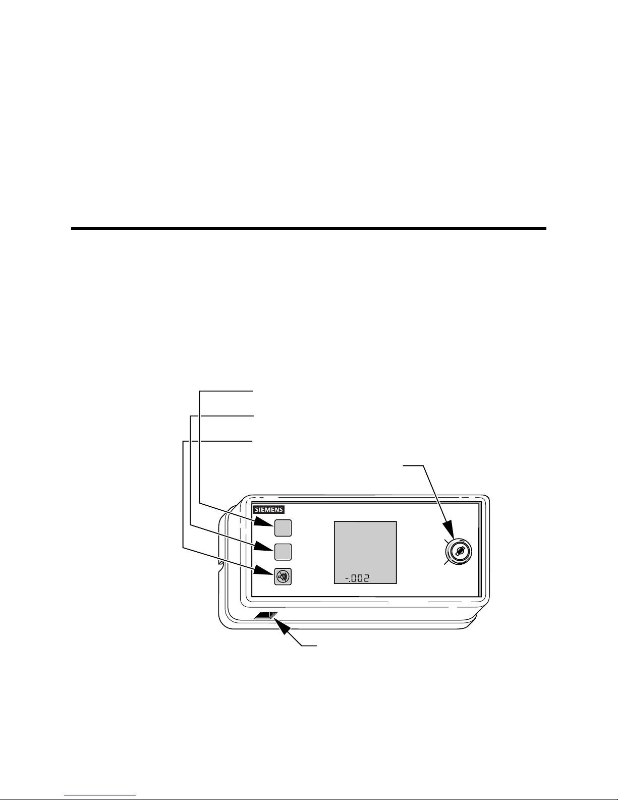
provides visual and audible alarms to alert a user of alarm conditions (
NORMAL LED (GREEN)
ALARM LED (RED)
HORN SILENCE BUTTON
PRESSURE MODE KEY SWITCH
(OPTIONAL)
SWITCH OVERRIDE DOOR OPEN
HIGH PRESSURE LOW PRESSURE
GENERAL FAILURE ANTEROOM
NEGATIVE ISOLATION
PROTECTIVE ISOLATION
INFECTIOUS ISOLATION
NEGATIVE PRESSURE
POSITIVE PRESSURE
INCHES OF H20
PORTABLE OPERATOR’S
TERMINAL PORT
Infectious Isolation/
SEN0175R3
Normal
Alarm
Horn
Silence
Siemens Building Technologies, Inc. 1
Figure 1. Differential Pressure Monitor.

Differential Pressure Monitor Owner’s Manual
Ordering Notes
Differential Pressure Monitor with Keyed
Switch for negative pressurization.
Differential Pressure Monitor with Keyed
Switch for positive pressurization.
Differential Pressure Monitor without
Keyed Switch.
Related Equipment
Remote Pressure Transmitter for use with
the Differential Pressure Monitor.
Calibration tool for Remote Pressure
Transmitter.
Hardware Inputs
Digital
•
Remote pressure transmitter (2 for App. 702 and 704, patient room and anteroom)
Door switch (optional)
•
547-005
547-006
547-002
547-003
547-004
Hardware Outputs
Analog
4-20 mA pressure signal
•
2-value resistive signal to identify pressurization mode to Room Pressurization
•
Controller
Digital
Alarm relay
•
2-state signal for pressurization mode to Constant Volume Controller
•
2 Siemens Building Technologies, Inc.

Components
The components of the DPM include:
LCD Messages
The LCD shows the differential pressure of the room in inches of H2O or Pascals. It also
shows the status of the DPM with the following messages:
•
Liquid Crystal Display (LCD)
Light Emitting Diodes (LEDs) (2)
•
Horn Silence Button
•
Portable Operator’s Terminal Port
•
Pressure Mode Key Switch (optional)
•
Chapter 1 – Hardware
LCD Message… Indicates that the…
LOW PRESSURE room differential pressure is below the user-
defined limit.
HIGH PRESSURE room differential pressure is above the user-
defined limit.
DOOR OPEN door to the occupied space is open if it is being
monitored.
GENERAL FAILURE RPT has lost power or the DPM is not receiving
the pressure signal from the RPT.
SWITCH OVERRIDE database points that determine pressurization
mode have been set from a field panel. This
overrides the pressure mode key switch position,
rendering it ineffective.
ANTEROOM LCD is displaying the anteroom pressure in
response to pressing the Horn Silence button, or
anteroom differential pressure is not being
maintained.
NO ISOLATION device is monitoring for neutral pressure.
PROTECTIVE ISOLATION /POSITIVE
PRESSURE
INFECTIOUS ISOLATION/NEGATIVE
PRESSURE
device is monitoring for positive pressure
(Applications 701 and 702).
device is monitoring for negative pressure
(Applications 703 and 704).
Siemens Building Technologies, Inc. 3

Differential Pressure Monitor Owner’s Manual
LED Status
The LEDs indicate the following status:
LED color… Indicates that the DPM is operating in…
Green a normal condition.
Red an alarm condition.
Button Functions
The Horn Silence button on the DPM has the following functions:
Button Functions
Horn Silence • Pressing this button turns the alarm horn OFF
• For Applications 702 and 704 only. The following
(applies to all applications).
function applies to Applications 702 and 704 when
displaying the differential pressure of the anteroom:
Pressing the Horn Silence button for 5 seconds
displays the “ANTEROOM” descriptor and the
anteroom differential pressure on the LCD.
Pressure Mode Key Switch (Optional)
The Pressure Mode Key Switch (optional) allows the operator to locally select the pressure
mode.
Remote Pressure Transmitter
The Remote Pressure Transmitter (RPT) is a Siemens Building Technologies, Inc.
Laboratory Control product. The RPT (
between a room and the adjacent space. The RPT sends that measurement to the
Differential Pressure Monitor.
Components
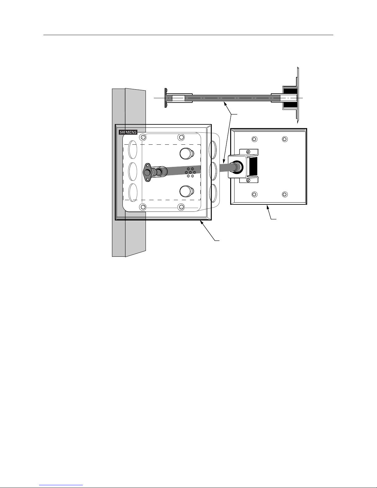
The components of the RPT include (Figure 2):
•
Inside cover plate
Outside cover plate
•
Airflow tube
•
Figure 2) measures the difference in air pressure
4 Siemens Building Technologies, Inc.
Chapter 1 – Hardware
AIRFLOW TUBE
OUTSIDE
COVER PLATE
INSIDE
COVER PLATE
SEN0179R2
Figure 2. Remote Pressure Transmitter
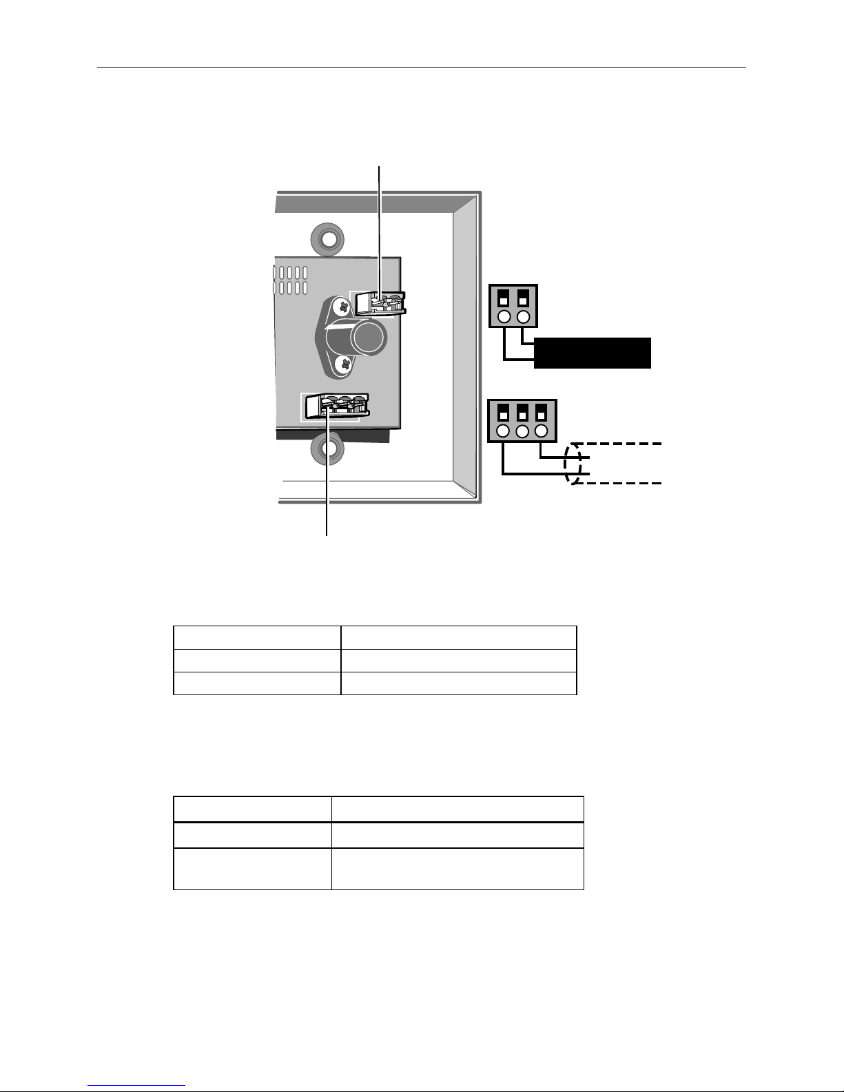
Circuit Board
The printed circuit board of the RPT (Figure 3) is the pressure signal generating area. The
circuit board is not visible once the RPT is installed. The following components are hidden
once the RPT is installed:
• • 24 Vac (wire receptacle)
Pressure signal (wire receptacle)
Siemens Building Technologies, Inc. 5
Differential Pressure Monitor Owner’s Manual
PIN #1
+
-
1 2 3
+ -
24V TRUNK
TO DPM
PRESSURE SIGNAL
SEN0177R1
PIN #1
Figure 3. RPT Circuit Board.
Operating and Power Specifications
Operating temperature
Operating range
Power consumption
65° to 85°F (18.3° to 29.5°C)
24 Vac, 50/60 Hz
1.4 VA, Class 2, at 24 Vac
Pressure Signal Output Definition and Specification
The pressure signal output is a digital pulse signal that represents the measured pressure
difference across the sensor.
Operating Range
Recommended Wire
Recommended max.
wire length
0-5 volt rectangular wave, 0-10 KHz
2 Conductor, 18 AWG Shielded Cable.
500 ft (152.4 m)
6 Siemens Building Technologies, Inc.
 Loading...