

Siemens 100-8D,100-8 Technical Manual
SIEMENS

SIEMENS
Floppy Disk Drive FDD 100-8
INTRODUCTION
OPERATION
THEORY OF OPERATION
INSTALLATION
Technical Manual
Volume 1 Model 100-8D
TABLE OF CONTENTS
1 IN T R O D U C TIO N .................................................................................................... 1-1
General .................................................................................................................. 1-1
Scope ..................................................................................................................... 1-1
De sc ription ....................................................................................................... 1-1
Disk C a r t r i d g e ................................................................................................ 1-3
Recording F o r m a t ......................................................
...
...............................
1-5
Encoding S c h e m e ......................
...
............................................................ 1-5
Trac k F o r m a t ............................................................................................. 1-5
Sector Fo r m at
.........................
...
............................................................ 1-6
Sector Content .................................................................................. 1-6
32-Sector F o r m a t ........................................................................... 1-6
IBM 37 40 Form at ........................................................................... 1-7
Disk Drive A s s e m b l y .................................................................................. 1-8
Printed Circuit Board .............................................................
...
1-8
Main Deck A s s e m b l y ........................................................................... 1-9
C a rrier A s s e m b ly .................................................................................. 1-9
Options-F ea tu r e s
.........................
...
.................
...
.................
...
..................... 1-9
Write P r o t e c t ............................................................................................. 1-1
Binary Select
. . . . . . .
................................
. ............................. 1-10
Radial Select ............................................................................................. 1-10
Hard S e c t o r ................................................................................................ 1-11
16/8 Sector ................................................................................................ 1-11
Auto E ra s e .................................................................................................... 1-11
Data Se parator (FM O n l y )
..................
...
...............................
...
1-11
Auto Head Load .......................................
...
1-12
Activity Indicator .................................................................................. 1-12
PC B A ssem bly Option C o n fig u r atio n s .................................... 1-12
Sp e cifi c a tio n s......................................................................................
...
1-12
2 O P E R A TIO N
................................
.............................................................................. 2-1
Gene r a l ......................................................................................
...
........................
2-1
Daily O p er a tio n ................................................................................................ 2-1
Floppy Disk Handling and S to ra g e ............................................... 2-1
Floppy Disk Loading and U nlo ad in g
...............
...
2-2
W rit e - P r o t e c t
.............................
...
............................................................ 2-3
ILL
Section Page
TABLE OF CONTENTS (Continued)
3 THEORY OF OPERATION
........................................................................ 3-1
G e n e r a l.............................................................................................................. 3-1
Control S y s te m
.....................
...
. .
....................................................... 3-2
Command Execution
..................
...
................................................... 3-2
Status S e n sin g .......................................................................................... 3-3
Positioning System ................................................................................... 3-3
Stepper Motor C o n t r o l .......................................................
...
3-3
Stepper M o t o r .......................................................................................... 3-4
Carriage A s s e m b l y ............................................................................ 3-4
Read/W rite S y s t e m ................................................................................... 3-4
Read/Write Operation ..................................................................... 3-4
Functional D es c r ip t i o n ............................................................................ 3-5
Spindle Drive S y s t e m
........................................................................ 3-6
Spindle System ...............................
«............................................ 3-7
Read/W rite Head Positioning System ................................... 3-7
Head Load S y s t e m
............................................................................... 3-8
Control and Data T i m in g .................................................................. 3-8
Logic Con v ention s
..............
...
.................................................................... 3-10
Detailed Logic D e s c r i p tio n ................................................................. 3-10
Control L o g i c ................................................................................................ 3-10
Select ............................. ........................................................................... 3-13
Binary Select (Option)........................................................................ 3-14
Index/Sector D e t e c t i o n ..................................................................... 3-15
Hard Secto r (Option)............................................................................ 3-16
Ready ...............................
...
..........................................................
...
3 - 16
Activity Indicator ..................
...
.......................................................... 3-18
Door Lock (Option)
..............
...
............................................................. 3-19
Disk C h a n ge .............................................
...
3-19
Read /W rite Head Positioning Logic
............................................. 3-20
Head L o a d ................................................................................................ 3-20
Track 00 Switch ..............................................................
...
.................
3-20
Stepper Motor Drive ......................................................................... 3-22
Interface Gating. ...........................................................
...
3-22
State Counter ................................................................................... 3-22
Stepper Motor D river s .............................................................. 3-23
Stepper Motor ............................................................................... 3-24
Read/W rite L o g i c ...................................................................................... 3-25
Write-Protect . .................................................
...
3-26
Write Mode ............................................................................................. 3-26
Write and E rase Gating .......................................................... 3-26
Erase L o g i c .......................................................
...
...........................
3-27
DC U n s a f e .......................................................................................... 3-28
Write Current Control .............................................................. 3-29
Low Write Current C o n t r o l
...............................
...
................. 3-30
Section Page
iv
TABLE OF CONTENTS (Continued)
3 THEORY O F OPERATION (Continued)
Read M o d e ......................
...
.......................................................................... 3-31
Read/W rite S e l e c t ........................................................................... 3-32
Read LSI Circuit, Read Amplifier, and Filt e r . . . 3-32
Differentiating Network
..................
...
. e . s s « ................ 3-34
Crosso v e r Detector ....................................................................... 3-35
Time Domain Filter .................................................................... 3-35
FM Data Separator (Option)............................................................. 3-36
Term inating R e sistor Network . ............................................... 3-37
4 INS T A L LA TION....................................................................................................................... 4-1
G e n e r a l
................................................................
...
.............................................. 4-1
Inspection
............................................................................................
...
4-1
Unpacking
.........................
...
.............................................................................. 4-1
Mechanical Checks .............................................................'
.......................
4-2
Connecting C a b l e s ...............
...
.....................................................
...
4-2
AC Po w er C a b l e ...................................................................................... 4-4
DC Power C a b l e ...................................................................................... 4-5
Interface Signal Cable ...............
...
.................
...
................................ 4-5
Interface Signal Descriptions ...............
...
...................................
...
. 4-6
Logic Levels and T e r m in a t io n ...................................................... 4-6
Input S i g n a ls................................................................................................ 4-8
Output S i g n a ls............................................................................................. 4-8
Interface T i m i n g
.......................................
...
.................................................
4-8
Sy stem C o n fig ura t io n s
.......................................
...
................................... 4-12
Single-Drive C o n fig u ra t i o n ............................................................. 4-12
Radial Sele ct......................................................................................... 4-12
Daisy-Chained Radial S e l e c t .................................................. 4-13
Binary S e l e c t
..............
...
...............................
...
...............................
4-14
Interfac e/Intern al Options Installation ........................................... 4-16
Radial Select
................................
...
........................................................ 4-16
Binary Select" ...........................................
...
.............................................. 4-18
Radial S t e p ...............
...
................................................................................. 4-18
Radial Ready
.......................................
...
4-19
Ready Option ............................................................................................. 4-20
Radial I n d e x /S e c to r
...............
...
............................................................ 4-20
Radial Head Load O p tio n .................................................................... 4-20
Auto Head Load O p ti o n .............................
...
.....................
...
4-21
Hard S e c t o r
..............................................
...
.............................................
4-22
16 or 8 Sector ..................
...
................................................................... 4-22
Activity Indicator S e l e c t...........................................
...
.................
...
4-22
FM Data S e p arato r . . ..................
...
.................................................
4-23
Section Page
v
TABLE OF CONTENTS (Continued)
4 INSTALLATION (Continued)
Tunnel-Erase Option ......................................
...
........................
...
4-23
Write P r otect O p ti o n
..............................................................
...
4-23
Disk Change Option ............................................................................ 4-24
Pha se O p t i o n .......................................................
...
..............................
4-24
Installation .................................................................................................... 4-25
Mounting D im e n sio n s
........................................................................ 4-25
Section Page
vi
LIST OF ILLUSTRATIONS
Figure Page
1-1 Floppy Disk Drive Model F D D 1 0 0 - 8 D
1-2 Floppy Disk and Protective Envelope
..............................................
..............................................
1-1
1-3
1-3 Single and Double Density Encoding .................................................. 1-5
1-4 32-Sector F o r m a t ..............................
... .
........................................
...
1-6
1-5 IBM 3740 F orm at ........................................................................................... 1-7
1-6 Physical Dim ensions and Mounting p r o v i s i o n s
2-1 Floppy Disk and Storage Envelope
..............
..........................
. . . .
.......................
1-16
2-2
2-2 Floppy Disk Loading .................................................................................... 2-3
3-1 Floppy Disk D r i v e, Simplified Block Diagram
3-2 Detailed Functional Block D i a g ra m
3-3 Spindle Drive S y s t e m
...................
..................................................... 3-5
...
............................................................. 3-6
..........................
3-1
3-4 Spindle S y s t e m .................................................................................................. 3-7
3-5 Read/W rite Head Positioning S ystem ............................................... 3-8
3-6 Control and Data T im in g .............................................................................. 3-9
3-7 Interface Logic L e v e l s .....................................................
...
.......................
3-10
3-8 Logic S y m b o lo g y .............................................................................................. 3-11
3-9 Select L o g i c ......................................................................................................... 3-13
3-10 Index D etection Logic ................................................................................ 3-15
3-11 Index Timing ..................................................................................................... 3-lo
3-12 Hard Sector and 16/8 Sector Option L o g i c
....................................
3-17
3-13 INDEX/SECTOR T i m i n g .............................................................................. 3-17
3-14 Ready L o g i c ........................................................................................
...
3-18
3-15 Head Load L o g ic ............................................................................................... 3-19
3-16 Track 00 L o g ic
...................
...
.......................................................................... 3-21
3-17 Track 00 Timing .............................................................................................. 3-21
3-18 Stepper Motor Interface Gating L o g ic ............................................... 3-22
3-19 Stepper Motor Timing ................................................................................. 3-23
3-20 Stepper Motor Drivers Logic ................................................................ 3-24
3-21 Write Initiate T i m in g
3-22 W rite -P r o tect Logic .........................................................
3-23 Write and E rase Gating L o g ic
........................
................
...
.................* .................................. 3-25
...
...
.................
.......................
... .
....................
3-26
3-27
3-24 E rase L o g i c ......................................................................................................... -*-28
3-25 Erased Data P a t t e r n
3-26 DC Unsafe L o g i c .................................................................................
3-27 Write Current Control L ogic . . . . . .
........................
...
....................
..............................
... .
....................
...
. 3-29
...
3-29
...
3-30
vii
LIST OF ILLUSTRATIONS (Continued)
Figure Page
3-28 Write Current S w i tch in g
............................................................................ 3-31
3-29 Write Current Timing ................................................................................ 3-32
3-30 Read Initiate Timing .................................................................................... 3-33
3-31 Read Logic, Simplified Diagram ........................................................ 3-33
3-32 Read P ream p lifier and F i lter C ir c u i t .............................................. 3-34
3-33 Differentiating Netw o rk....................................
...
......................................... 3-34
3-34 Read Data Waveforms
..........................................
...
.................................. 3-35
3-35 Time Domain Filter Logic ...................................................................... 3-35
3-36 FM Data Separator (Option) Logic ..................................................... 3-35
3-37 FM Data Separator Output Timing ..................................................... 3-36
3-38 Terminating R e s istor N e tw o rk ............................................................... 3-37
4-1 Principal Parts Locatio n ............................................................................. 4-3
4-2 AC Connector J 2 .............................................................................................. 4-5
4-3 DC Connector J 2 .............................................................................................. 4-5
4-4 Interconnecting D ia g ra m ............................................................................. 4-7
4-5 S ingle-Driv e C o nfig u ratio n ............................................................
...
4-12
4-6 Radial Selec t C o n figu r a t ion ...................................................................... 4-13
4-7 Daisy-C h ained Radial Sele ct C o n figura tion .................................... 4-14
4-8 Binary Select C onfig u ration
...................................................................... 4-15
4-9 Interface/internal O ption s.......................................................................... 4-17
viii

LIST OF TABLES
1-1 Floppy Disk C h a r a c t e r i s ti c s
..................
...
........................................ . 1-4
1-2 Principal S p ec ific a tio n s
.......................................
...
............................
...
. 1-13
2-1 Floppy Disk Loading and Unloading . , .........................
...
, , . . 2-3
3-1 Disk Drive Selection
........................................................................
...
3-14
4-1 AC Power R eq u i r em e n t s ............................................................................
...
4-4
4-2 DC Pow er Req uirements ............................................................................... 4-5
4-3 Reco m m ended J3 Mating C o n n e cto rs..................................
...
4-6
4-4 Interface Input S i g n a l s
.....................................
...
.......................................... 4-9
4-5 Interface Output Signals , , , , ................................................
...
4-11
Table Page
ix

SECTION 1
INTRODUCTION
GENERAL
This manual provides information on the de
theory of operation information for the Mod
(Figure 1-1).
SCOPE
The contents of this manual are intended
to be used for custom er introduction to the
disk drive, as a training document for
cu stomer engineers requiring detailed
theory of operation information and for
installation and maintenance information.
DESCRIPTION
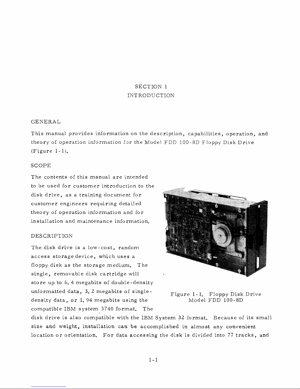
The disk drive is a low-cost, random
access storage device, which uses a
floppy disk as the storage medium. The
single, removable disk cartridge will
store up to 6. 4 megabits of double-density
unformatted data, 3. 2 m egabits of single-
density data, or 1. 94 m egabits using the
compatible IBM sy stem 3740 format. The
disk drive is also compatible with the IBM
size and w’eight, installation can be accoi
location o r orientation. F or data accessin
cription, capabilities, operation, and
1 FDD 100-8D Floppy Disk Drive
Figure 1-1. Floppy Disk Drive
Model FDD 100-8D
System 32 format. Because of its small
nplished in almost any convenient
I
the disk is divided into 77 tracks, and
1-1
each track can be subdivided into as man y as 32 sec tors. A stepper motor positions
the read/write head at the track to be accessed . Index and sector holes punched into
the disk are sensed photoelectrically to produce sec tor and index pulses that permit
accessing the individual sectors of a track. When the optional write-protect slot in
the protective envelope is uncovered the w rite-pro tected condition is sensed photo
electrica lly, and write operations are inhibited.
Up to eight d rives can be interfaced to a single host controller. The controller
controls disk drive selection, head loading, track addressing, and read/write data
transfers.
When a disk cartridge is inserted and the acce s s door is closed, the drive spindle
rotates the disk at 360 revolutions per minute. When se lected, the drive accepts
a head load command, causing the read/write head to be loaded to the disk. With
the drive selected, sector/in d ex puls es, write-p r otect sta tus, track 00 position
status, and a read/write ready status is supplied to the controller. At the desired
track, a data tran sfer operation is performed; read-to the con trolle r, write-from
the contr o lle r, depending on the state of the write command.
During a write operation (disk not write-protected ), write data is input to the write
circuits. Fo r each write data pulse receiv ed , a flux reversal is recorded on the
disk by the read/write head.
During a read operation, each recorded flux rev e rsal is sensed by the read/write
head, converted to a raw data pulse and supplied to the controller.
Applications for the Floppy Disk D rive include:
• Key Entry System s
• Poin t-of-S ale Recording System s
• Word P ro cessin g System s
• Batch Termin al Data Storage
• Small Business Sy stem s Data Storage
• M icro p rogram Loading and E r ro r Logging
• Minicomputer Programs and Auxiliary Data Storage
1-2
The drive provides random accessing of data with greater performance and
reliab ility and is an excellent alternate product to paper tape, reel-to - reel tapes,
card equipment, ca s settes, and cartridge drives.
DISK CARTRIDGE
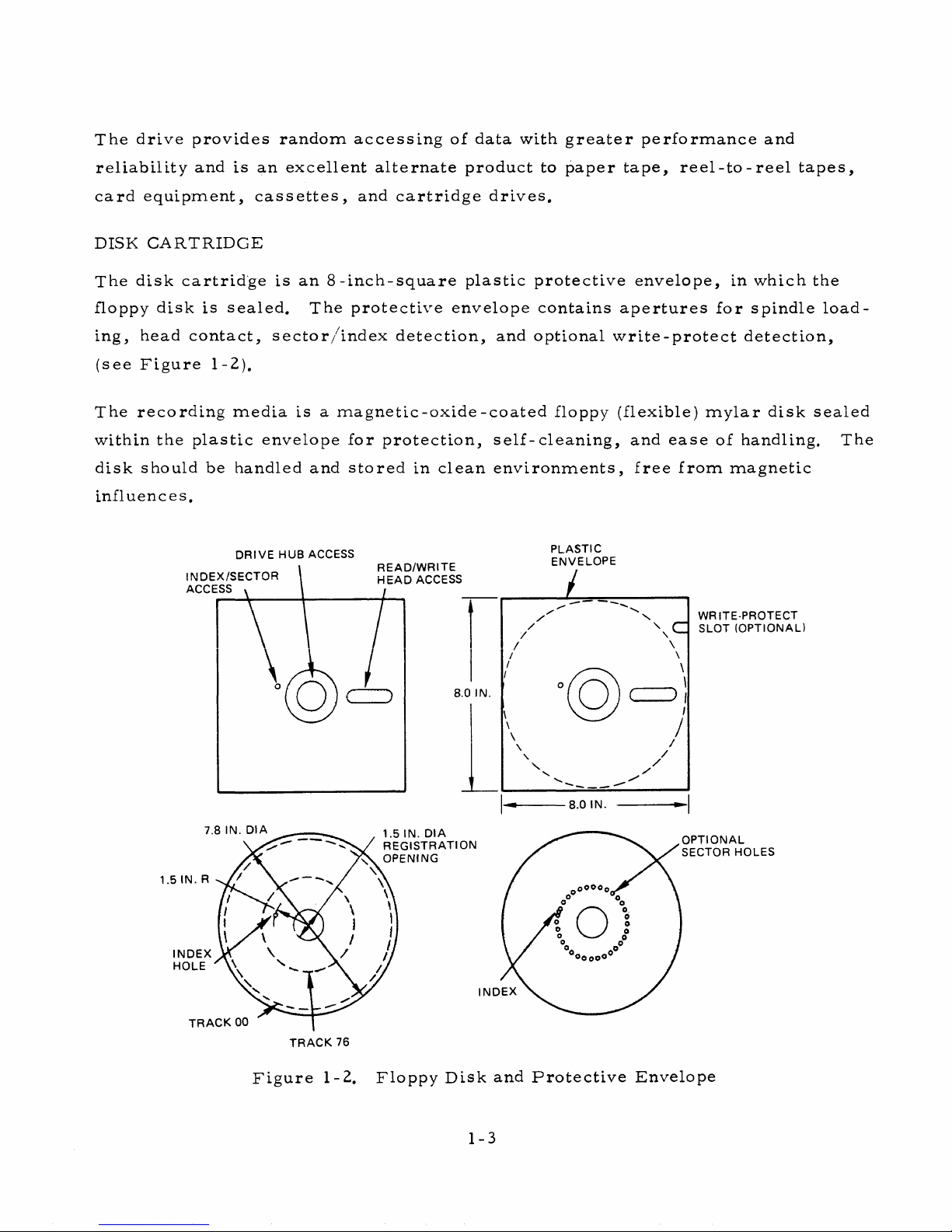
The disk cartridge is an 8 -inch -sq uare plastic protective envelope, in which the
floppy disk is sealed. The protective envelope contains apertures for spindle load
ing, head contact, secto r/index detection, and optional write-p rotect detection,
(see Figure 1 -2).
The recording m edia is a m agnetic-oxid e-coated floppy (flexible) m ylar disk sealed
within the plastic envelope for protection, self-cleaning, and ease of handling. The
disk should be handled and stored in clean environmen ts, free from magnetic
influences.
Figure 1-2. Floppy D isk and P rote ctive Envelope
1-3
At no tim e should the surface of the med ia be touched, or the surface of the
envelope be written on. When not in use, the disk cartridge should be returned
to its protective storage envelope.
For reliable op eration, floppy disks should be stabilized in the same environment
as the using disk dr ives, for a period of at le a st five m in u tes, prior to installation.
The recommended floppy disk m eets the requirem ents of the following documents:
X3138/77-118 Am erican National Standard for Single Sided
Unformatted Flexible Disk Cartridge.
GA21-9190 IBM One-Sided, Original Equipment Manufacturing
Information.
EC M A/TC 1 9/? 7 / l6 Data Interchange on 200 m m Disk Cartridges using
double frequency recording at 13,262 ftprad on one
side.
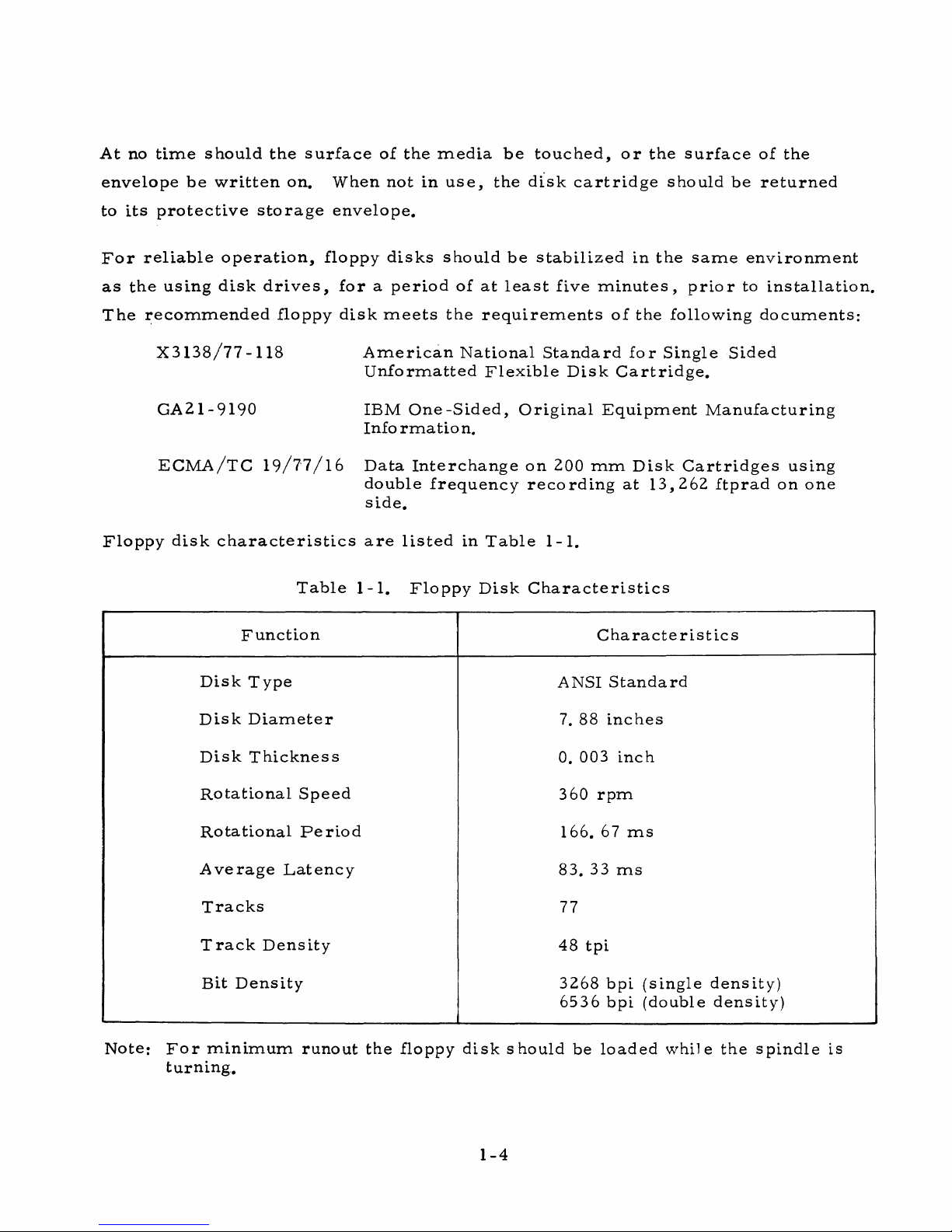
Floppy disk ch a racteristic s are listed in Table 1-1.
Table 1-1. Floppy Disk Cha racteristics
Function
Characteristics
Disk Type
ANSI Standard
Disk Diam eter
7. 88 inches
Disk Thickness
0. 003 inch
Rotational Speed
3 60 rpm
Rotational Period
166. 67 ms
Ave rage Latency
83. 33 ms
Tracks
77
Track Density
48 tpi
Bit Density
3268 bpi (single density)
6536 bpi (double density)
Note: For m inim um runout the floppy disk should be loaded while the spindle is
turning.
1-4
RECORDING FORMAT
The recording fo rmat l s dependent upon req u irem ents of the controller. The track
and s e ctor organization of data Is dependent on the format.
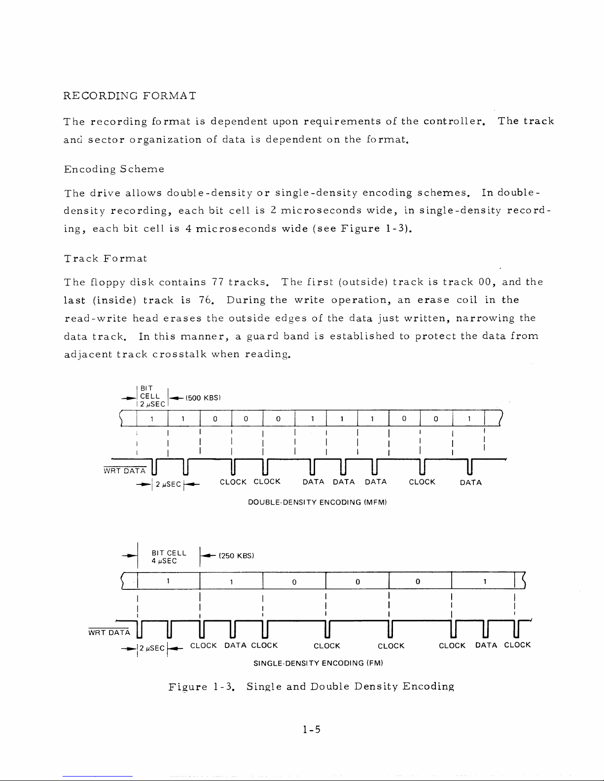
Encoding S chem e
The drive allows double-densIty or s Ingle-dens Ity encoding schemes. In double-
density reco rdin g, each bit cell Is 2 m icrosec o n d s wide, In s ingle-dens Ity rec ord
ing, each bit cell Is 4 mic roseconds wide (see Figure 1-3).
Track Fo r m a t
The floppy disk contains 77 tracks. The first (outside) tra c k is track 00, and the
last (Inside) track Ls 76. During the write operation, an era s e coll in the
re a d -w rlte head era se s the outside edges of the data just w ritten, narrowing the
data track. In this m anner, a guard band Is established to protect the data fro m
adjacent tra c k crosstalk when reading.
WRT DA TA
WRT DA TA
-► 1 CELL
12 mSEC
-* - (5 0 '0 KBS)
1
1
0
0 I 0
1
1 1
I I
I I
I I
FT
- ► ] 2 mSEC f— -
BIT C ELL
-
4 iuSEC
1
I
i n n n n r
j2 mSEC h - CLO CK D A TA C LO CK CLOCK CLO CK
j u i m j u if
CLOCK CLOCK DA TA D ATA DATA
DO U BLE -D E NSITY EN COD IN G (MF M)
(250 KBS)
1
0
i i ! i i
0
¥ u n n r
SING LE- DENS ITY E NCOD IN G (FM )
0
0
CLOCK DA TA
0 1
CLO CK D ATA CLOCK
1
Figure 1-3. Single and Double Density Encoding
1-5
Sector Form at
The number of sectors In each track Is determined by the application, and can
range from 1 to 32, depending on whether the soft-se c to r or h a rd-se c tor floppy
disk is being used.
When soft secto r operation is required, only one index hole is punched in the floppy
disk. With this disk, the controller uses the index pulse to define the sectors.
When hard secto r operation is required, the floppy disk used contains the index
hole plus 32 secto r holes spaced equidistant around the disk (se e Figur e 1-2).
The index hole is punched midway between sector holes 31 and 0. The double-
pulse of sector 31 and index ale rts the controller that the next pulse starts sector 0.
The index and sector holes are se nsed ph otoelectr ically, providing the pulses sup
plied to the controller.
Sector Content
The format of each secto r is determined by the application. Norm ally, preambles
and postam b les containing a stream of coded bytes are written at the beginning and
end of each se c tor, to provide data synchronization. Following the preamble of
each new track , an identification (ID) field is written containing the track and sector
numbers. Following the ID field, data bytes are written.
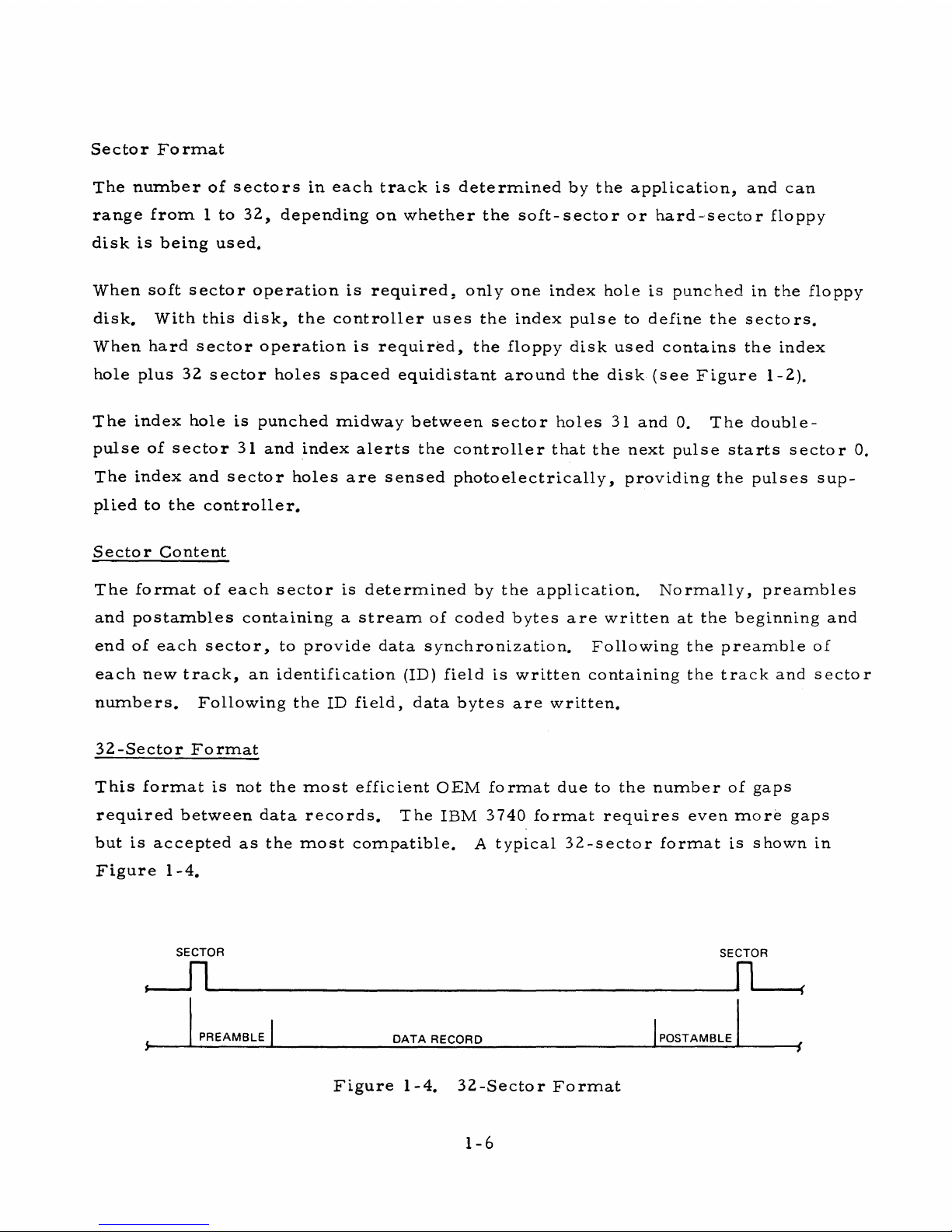
32-Sector F orm at
This format is not the m o s t efficient OEM format due to the number of gaps
required betw een data records. The IBM 3740 form at requires even m o re gaps
but is accepted as the m ost compatible. A typical 32-s e c to r format is shown in
Figure 1-4.
SECTOR
SECTOR
PREAM BLE
DA TA REC ORD
POSTAM BL E
Figure 1-4. 32-S ector Form at
1-6
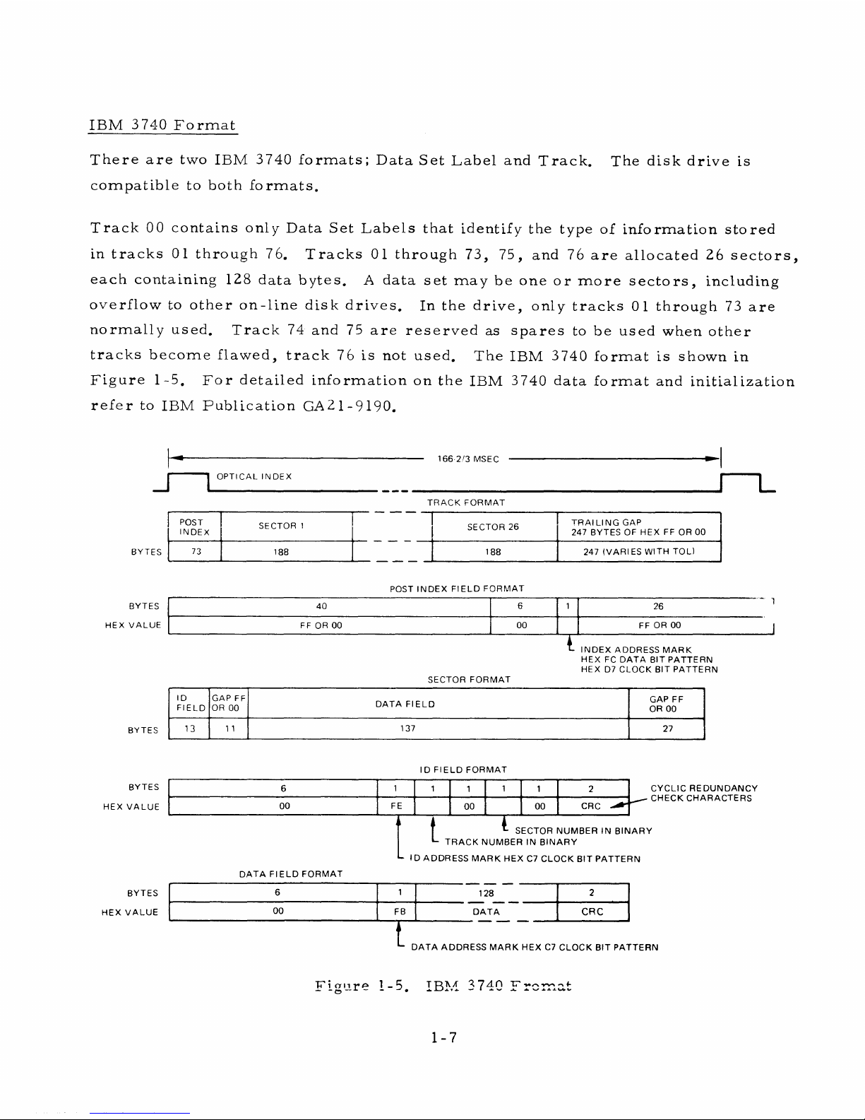
IBM 3 740 F o rm a t
There are two IBM 3740 form ats; Data Set Label and Track. The disk drive is
compatible to both form ats.
Track 00 contains only Data Set Labels that identify the type of information stored
in tracks 01 through 7 6. T r a cks 01 through 73, 75, and 76 are allocated 26 sectors ,
each containing 128 data bytes. A data set may be one or m o r e s e c tors, including
overflow to other on-line disk drives. In the drive, only tracks 01 through 73 are
no rm a lly used. T rack 74 and 75 are reserved as sp a res to be used when other
trac ks become flawed, track 76 is not used. The IBM 3740 form a t is shown in
Fig ure 1-5. For detailed information on the IBM 3740 data form at and initialization
re fe r to IBM Publication GA21-9190.
166-2/3 MSEC
J— L
OPTICAL INDEX
TRACK FORMAT
BYTES
J— L
POST
INDEX
SECTOR 1
SECTOR 26
TRA ILI NG GAP
247 BYTES OF HEX FF OR 00
73
188 188
247 (VARIES WITH TOL)
POST IND EX F IELD FO RMAT
BYTES
40 6
1
26
!
HEX VALUE
FF OR 00
00 FF OR 00 j
INDEX ADDRESS MARK
HEX FC DATA BIT PATTERN
HEX D7 CLOCK BIT PATTERN
BYTES
ID
FIELD
GAP FF
OR 00
DATA FIELD
GAP FF
OR 00
13
1 1
137
27
BYTES
HEX VALUE
BYTES
HEX VALUE
DATA FIELD FO RMAT
ID F IELD FO RMAT
6
1
1
1
1
1
2
00
FE
00 00 CRC
CYCLIC REDUNDANCY
CHECK CHARACTERS
t
L SECTOR NUMBER IN BINA RY
TRAC K NUMBER IN BIN ARY
L ID ADDRESS MAR K HEX C7 CLOCK BIT PATTERN
6
1
128
2
00
FB
DATA
CRC
I
DATA ADDRESS MA RK HEX C7 CLOCK BIT PATTERN
Figure 1-5. IBM 3 740 Frc
1-7
DISK DRIVE ASSEMBLY
The disk drive ass e m bly can be installed in a standard 19-inch RETMA rack; two
horizontally, or four vertically. The drive can also be mounted in a table-top for
top loading applications.
The disk drive com p rises three m ajor assem blies-
• Printed Circuit Board (Electronics)
• Main Deck A ssem b ly
• Carrie r Assem b ly
Printed Circuit Board
All electronic circuitry required to convert the digital data input and output to
and from analog data for the rea d /w r ite head and head positioning information is
contained on one circuit board. Interface and DC connectors can be provided.
Logic is TTL with sele cted d iscrete and IC Components. The electron ics perform
the following functions:
• Read Chain
• Write Chain
• Ready Generation
• Index Detection
• Stepper M otor Control
• Interface D r ivers and Receiver s
• W rite-Protect (Option)
• Index/S ector Separator (Option)
• FM Data Separator (Option)
• Binary Select (Option)
1-8

Main Deck Assem bly
The m ain deck a ssembly is the principal supporting asse m bly and contains the
following subassemblies;
Drive System
Positioning Svstem
Read Write S vs tern
Disk Cartridge Guide
and Ejector
Optical Sensing
- Spindle Drive m o tor, drive belt and pulley to
rotate spindle at 360 rpm.
- Stepping m o tor, lead s c rew and carriage, head
pressu re a rm and pressure pad to accurately
drive and position the read write head to the
desired track.
- Single-gap magnetic recording head with tunnel -
er a s e or s t raddl e - e rase feature. Read/w rite
head is contact type.
- Provides positive positioning and locking of disk
cartridge allowing prop er placement of the disk
cone. S pring-loaded ejection provides fast,
positive disk cartrid g e removal.
- Index and write - protect sensing by independent
LED and phototransistor sensing circuits. Also
track 00 sensing.
C a rrie r Assem bly
The c ar r i e r a s sem b ly is a secondary frame which pivots fro m the main deck
as sem bly and includes the following sub assem blies;
• Disk Centering Cone - P r e c isely cen ters and grips the floppy disk to the
s pindle.
• Head Load Mechanism - Solenoid, head p r e s s ure arm and pad. Ex erts
and sustains force, by the spring-loaded p r e ssu re
pad, to constrain the disk c artridge to the platten
and the read, write head.
Access Handle. Pushbutton latch release m echanism . Also
releases spring-loaded lock to discharge disk
cartridge.
OPTIONS-F E ATURES
The Floppy Disk Drive m ay be or d ered with basic configuration operating capa
bilities, or m ay be ord ered to include any or all available options. Each option
1-9
offers unique operating features. Severa l options have connections designed into
the main printed circuit board, for low - c o s t custom er enhancement.
W r ite-P ro tect
The write-p rotect feature provides a write-inhibit function when a write -protect
floppy disk cartridge is used. The stored data is protected only if the cartridge
write-prote ct slot is present. With the slot cov ered, all write functions are
enabled.
Binary Select
The Binary Select option perm its any one of up to eight disk drives to be selected.
With the option installe d, SELECT lines are not dedicated but are used to contain a
binary select code. The SELECT 0 line is used to enab le/d isab le unit se lection,
while the SELECT 1, SELECT 2, and SELECT 3 lines contain a binary code between
0 and 7. When the SELECT 0 line is low (true), a decoder in the Binary Select
option log ic decodes the select code from the controller.
Radial Select
In the b a sic configuration, the disk drive does not accept com mands from the
contr oller, and does not supply status signals to the controller, until selected.
The purpose of this option is to allow commands to be accepted and status signals
to be supplied, each over separate lin e s, without the drive selected. The following
signals can be optionally configured for radial operation:
• S T E P and STEP IN (Step Command)
HDLD (Head Load Command)
• READY (Ready Status)
• INDEX and SECTOR (Index and Sector Pulses)
When dedicated lines are provided for these sig n a ls, the disk drive need not be
selected by the controller. Each line m u st be assigned a separate pin number on
the interface connector. Spare pins are provided for this purpose.
1-10
The unit is modified for Radial Select operation by changing jumpers between the
existing etch pads. The etch pads are located on the main printed circuit board.
Hard S ector
In the b a sic configuration, the use of a hard sector disk causes the INDEX line to
produce one index pulse and 32 sector pulses per each disk revolution.
With the Hard Sector option installed, the index and sector pulses are separated
and supplied to the controller on independent INDEX and SECTOR lines.
16/8 Sector
When the Hard Sector option is installed, the addition of the 16/8 Sector option
provides a 2-bit binary counter that counts down the 32 sector pulses from a hard-
sector disk. This countdown perm its each track to be divided into 16 or 8 sectors,
instead of 32 sec tors. The output of the first stage (16 se c to r s ), or the second
stage (8 sectors) is connected to the SECTOR output line to the controller.
Auto Erase
The era s e turn-on and turn-off delays are internally controlled by the Erase logic.
When the controller activates WRITE, the leading edge of WRITE initiates a
200 -m icrose cond era se turn-on delay; the trailing edge of WRITE initiates a
530-m ic rosecond erase turn-off delay. If the straddle-e ra se configuration is used,
a str a ddle-e r a s e head m ust be installed. This option re m ov es the time delays.
Pads are provided for installation of this option.
Data Separator (FM only)
In the basic configuration, the RAW DATA line to the controller produces a pulse
for each flux reversal read from the disk. Consequently, the RAW DATA input
contains both clock and data pulses. F or this reason, the con troller must have
circu its that separate the clock and data pulses.
The Data Separator option is installed for the disk drive to operate in the sin gle
density encoding mode (FM) only. When installed, this option separates the data
and clock pulses input o ver the RAW DATA line. Data pulses are supplied to the
1-11
controller o ver an FM SEP DATA line, and synchronized clock pulses over an
FM SEP CLK line. Proper operation of the Data Separator option is based on a
format with no m issing clock pulses.
Auto Head Load
In the basic configuration, the re ad/write head Is automatically loaded when the
unit is sele c ted, and is automatically unloaded when the unit Is deselected. Alterna
tively, the unit m a y be configured to load the head in resp onse to a HDLD command
from the controller.
Activity Indicator
In the basic configuration, the activity Indicator is on when the drive Is selected.
The Activity Indicator option provides a m eans of substituting for the SELECT
status sig nal, one of the following status signals:
• HEAD LOAD
• RDY
Etch pads are provided on the m ain printed circuit board to optionally OR either
of the above signals with IN USE.
PCB A ss e m b ly Option Configurations
The m ain printed circuit board can be supplied in a b asic configuration or with the
optional configuration including Hard Sector and Data Separator.
SPECIFICATIONS
A com prehensive list of principal specifications are provided in Table 1-2. The
list defines both sin gle-d en sity and d ouble-density c h ara cteristics, both disk drive
and interface logic le ve ls , and all physical and electrical par am eters.
1-12
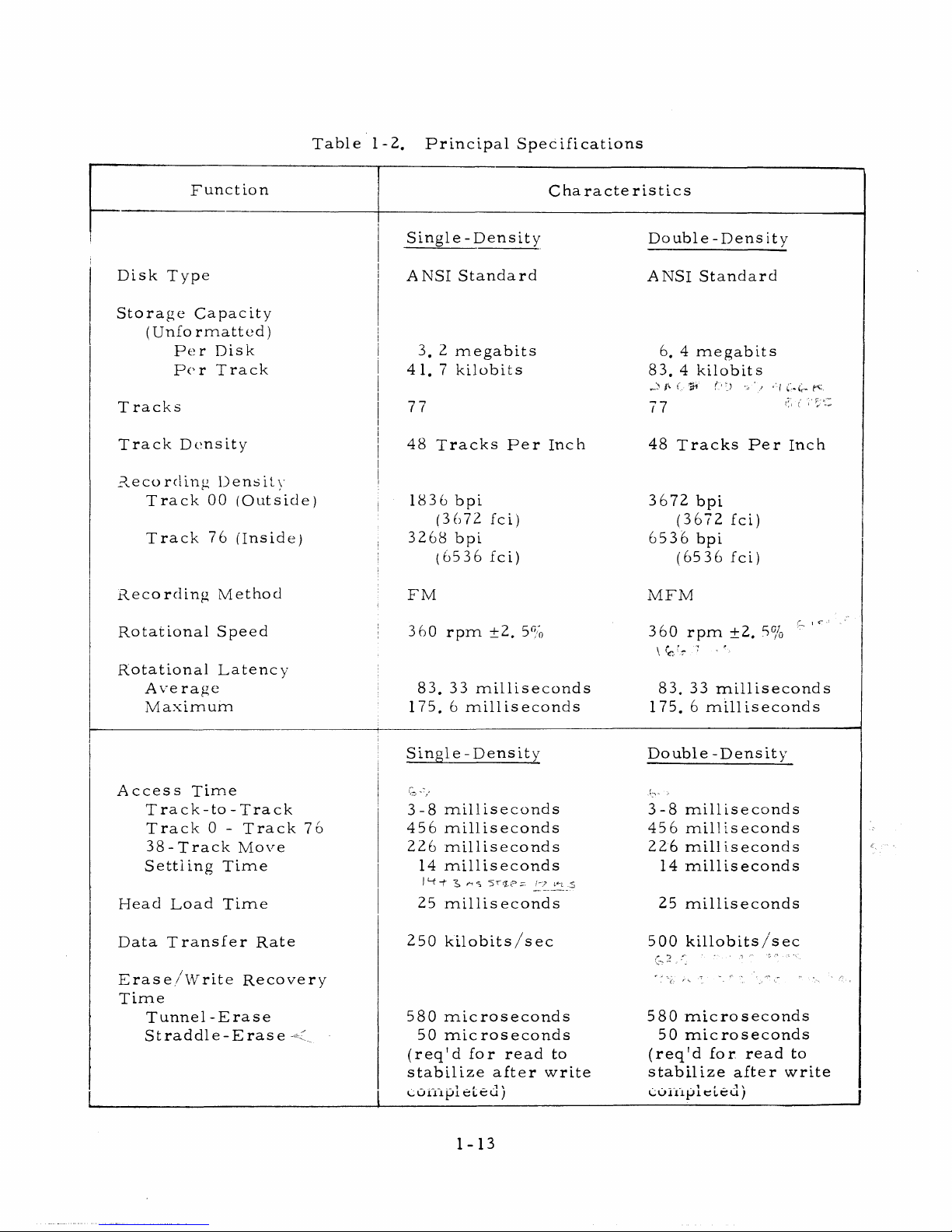
Table 1-2. Principal Specifications
Function
Characte ristics
Single -Density
Double - Dens ity
Disk Type
A NSI Standard
ANSI Standard
Storage Capacity
(Unfo rmatted)
Pe r Disk
Pe r Track
3. 2 megabits
41.7 kilobits
6. 4 megabits
83. 4 kilobits
T racks
77
77 <r.c
Tra ck Dens ity
48 Tracks P e r Inch
48 T rack s P e r Inch
Recording Density
Tra ck 00 (Outside)
Track 76 (Inside)
1836 bpi
(3672 fci)
3 2 68 bpi
(6536 fc i)
3672 bpi
(3672 fci)
6536 bpi
(6536 fci)
Recording Method
FM
MFM
Rotational Speed 3 60 rpm ±2.
5%
3 60 rpm ±2. 5%
\ y>r-r
:1 '
83. 33 milliseconds
175. 6 milliseconds
Rotational Latency
Average
Maximum
83. 33 milliseconds
175. 6 milliseconds
Single - Density
Double -Density
Acce ss Time
Track -to -Track
Tra ck 0 - Track 76
38 - Track Move
Settling Time
Head Load Time
3-8 milliseconds
456 milliseconds
226 m illiseconds
14 milliseconds
I'-f-f'
S ^ 5 r
,";.p m..s
25 milliseconds
3-8 m illiseconds
456 milliseconds
226 milliseconds
14 m illiseconds
25 milliseconds
Data Tran sfer Rate 250 kilobits/sec
500 killobits/sec
Era s e/W rite Recovery
Time
Tunnel -E ra s e
Straddle-E r a s e -<
.
580 m icrose conds
50 m icro s econds
(req'd for read to
stabilize after write
___
.
i
_ .1
\
Luiapi cicu
)
580 m icrosecond s
50 microseco nds
(req'd for read to
stabilize after write
COixiplelcu)
1-13
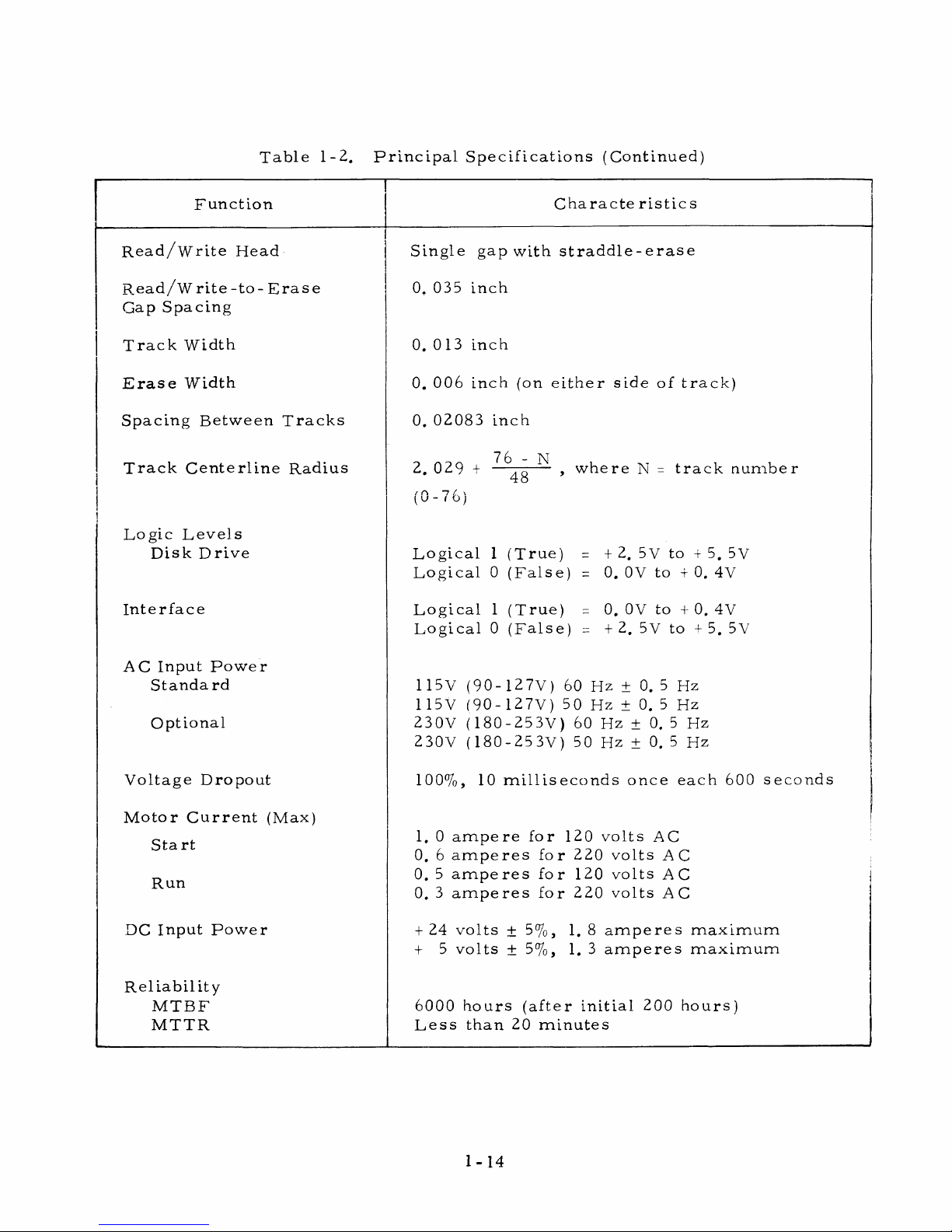
Table 1-2. Principal Specifications (Continued)
Function
Characte r is tic s
Read /W rite Head
Single gap with s tra d d le - e r a se
Rea d /W rite -to- E ra se
0, 035 inch
Gap Spacing
Track Width
0. 0 13 inch
E r a se Width
0. 006 inch (on either side of track)
Spacing Between T racks
0. 02083 inch
Tra c k Centerline Radius
2. 029 + ,Q , where N - track num ber
4 o
/ n
n L \
yu-(V)
Logic Levels
Disk Drive
Logical 1 (True) = +2. 5V to + 5. 5V
Logical 0 (False) = 0. 0V to + 0. 4V
Interface
Logical 1 (True) = 0. 0V to + 0. 4V
Logical 0 (False) = +2. 5V to + 5. 5V
AC Input P ow e r
Standa rd
115V (90- 127V) 60 Hz ± 0. 5 Hz
115V (90- 127V) 50 Hz ± 0. 5 Hz
Optional
230V (180-253V) 60 Hz ± 0. 5 Hz
230V (180 - 25 3V) 50 Hz ± 0. 5 Hz
Voltage Dropout 100%, 10 milliseconds once each 600 seconds
Motor C u rrent (Max)
|
Start
1. 0 am p e re for 120 volts AC
0. 6 am peres for 220 volts AC
Run
0. 5 am peres for 120 volts AC j
0. 3 am peres for 220 volts AC
DC Input Power
+ 24 volts ± 5%, 1. 8 am peres maximu m
+ 5 volts ± 5%, 1. 3 am p e r e s m ax i m um
Reliability
M T B F
6000 hours (after initial 200 hours)
MT T R
Less than 20 minutes
1-14
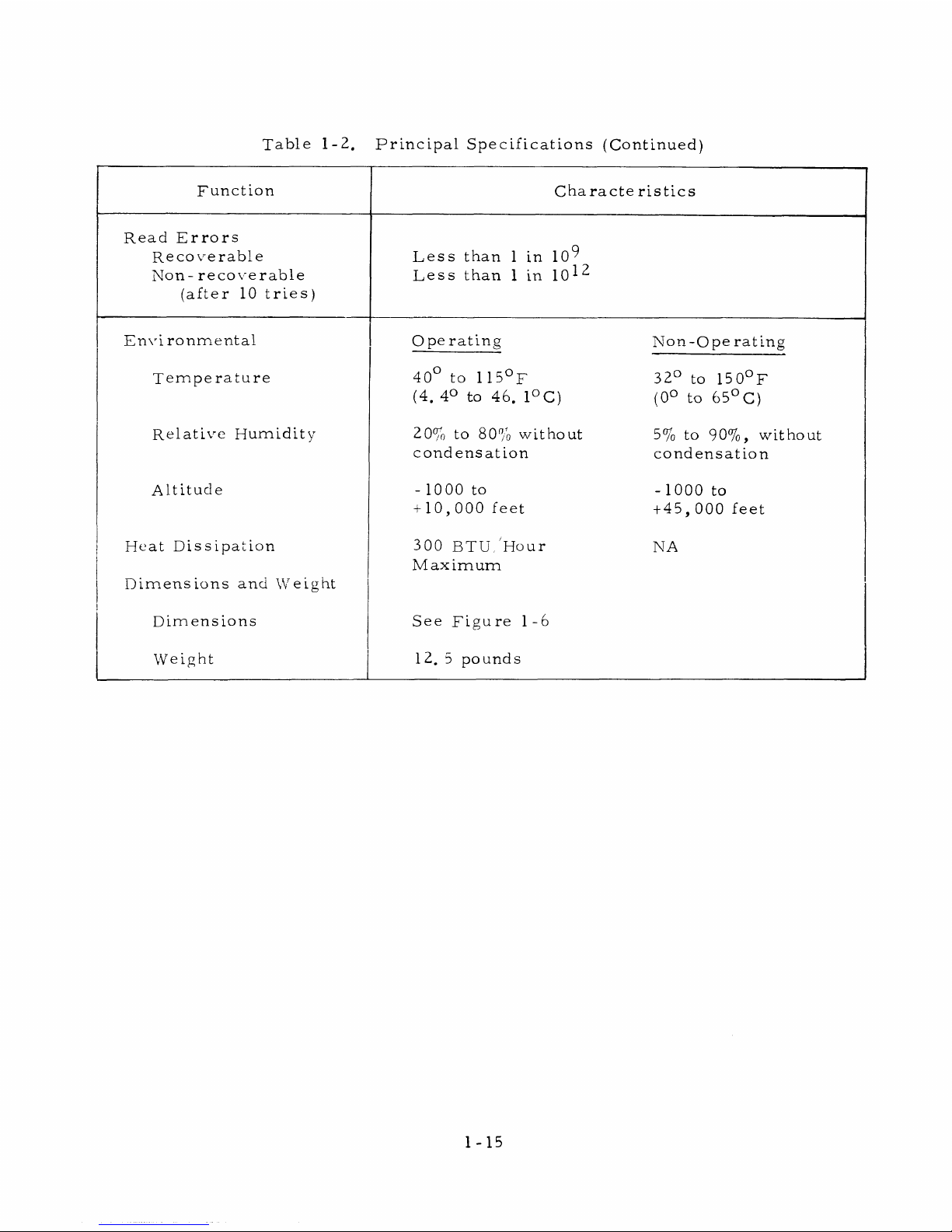
Table 1-2. Principal Specifications (Continued)
Function
Characte r is tics
Read E rro rs
Recoverable
Non-reco v e rable
(after 10 tri e s )
Less than 1 in 10^
Less than 1 in 1 0 ^
Envi ronmental O pe rating
Non-Ope rating
Tem p e rature
40° to 115°F
(4. 4° to 46. 1°C)
32° to 150°F
(0° to 65°C)
Relative Humidity
20% to 80% without
condensation
5% to 90%, without
condensation
Altitude - 10 00 to
+10,000 feet
- 1000 to
+4 5,000 feet
Heat Dissipation
Dimensions and Weight
300 BT U /Hour
Maxim um
NA
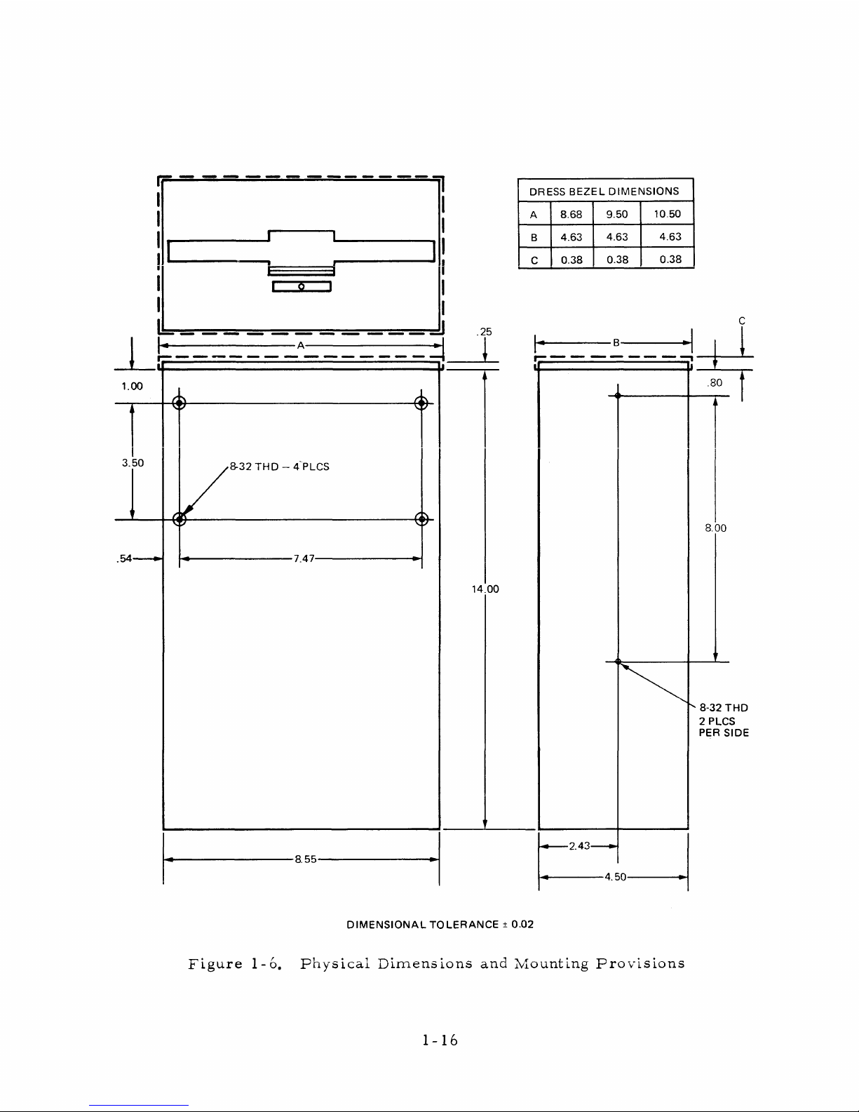
Dimensions See Figure 1-6
Weight
1 2. 5 pounds
1-15
1.00
3.5 0
.54-
8-32 T H D — 4 PLCS
■7.47-
-8.5 5-
&
14.00
DRESS BEZEL DIM E N SIO N S
A
8.68
9.5 0
10.50
B
4.6 3
4.6 3
4.6 3
C
0.3 8
0.3 8
0.3 8
8-3 2 T H D
2 PLCS
PER SIDE
DIM ENSIO NAL T O L E R A N CE ± 0.02
Figure 1-6. Physical Dimensions and Mounting Provisions
1-16
SECTION 2
OPERATION
GENERAL
The Floppy Disk Drive opera tes under complete control of the host controller,
after a floppy disk has been manually inserted. A front panel indicator is p ro
vided to indicate operating status.
DAILY OPERATION
The operating environment and the op e ra to r's careful handling of the disk drive
and the floppy disks enhance the appearance, and greatly extend the operating life
of the equipment.
Floppy Disk, Ilandl ing and Storage
The floppy disk is the data storage medium. The disk is sealed in a protective
envelope, in which are access holes for the read/writ e head, index and s ecto r
holes, disk centering hole, and optional write-p rotect slot (see Figure 2-1).
For external e r r or - f re e operation of the disk drive, the following disk handling
practic es a re recom m ended:
• P rior to use, place in same operating environm ent as disk drive, for at
least 5 minutes
• Never - place heavy objects on envelope
- write on protective envelope, only on label
- touch disk surface while handling
- attempt to clean disk surface
• Always - return floppy disk to storage envelope when not in use.
2-1
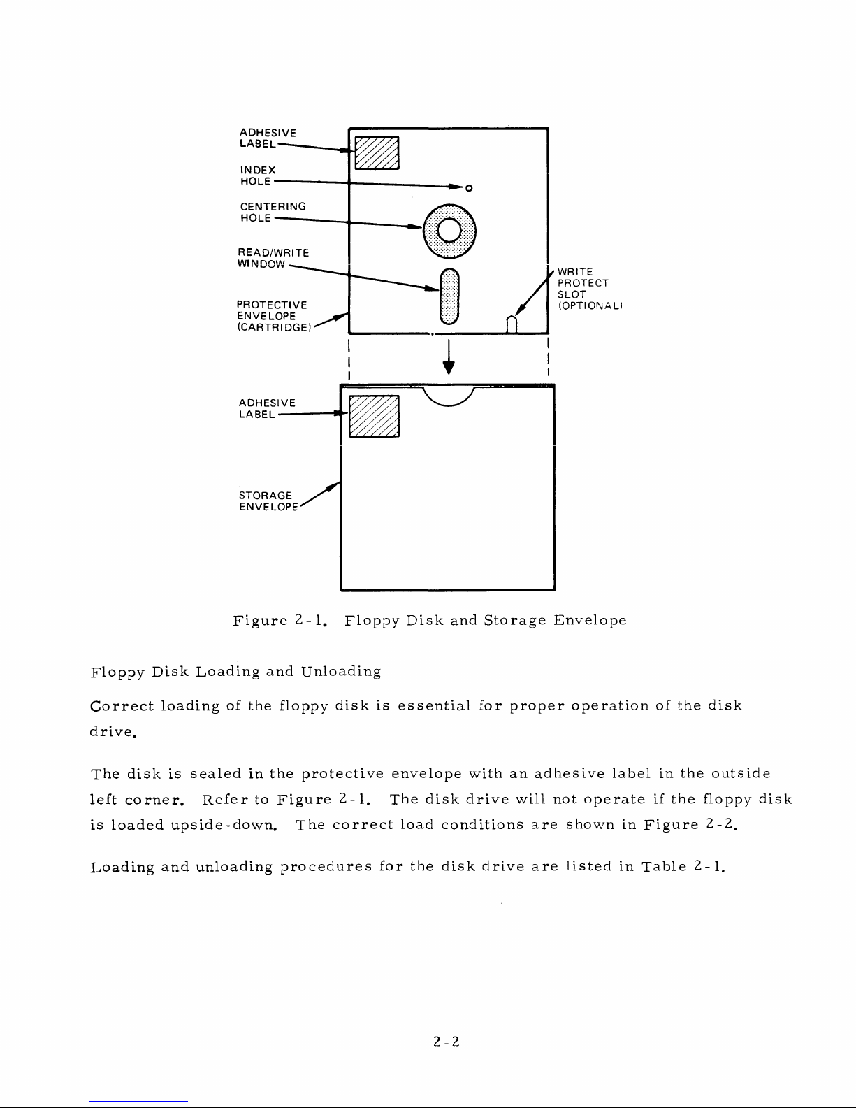
Figure 2-1. Floppy Disk and Storage Envelope
Floppy Disk Loading and Unloading
Correct loading of the floppy disk is essential for pro p er operation of the disk
drive.
The disk is sealed in the protective envelope with an adhesive label in the outside
left corner. Refer to Figure 2-1. The disk drive will not o perate if the floppy disk
is loaded upside-down. The c o rrect load conditions a re shown in F igure 2-2.
Loading and unloading procedur es for the disk drive are listed in Table 2-1.
2-2
 Loading...