

Page 1
Series 1000 Room Temperature
Sensors, 1K Ω Platinum (375α) RTD
(MBC/RBC/MEC/UC)
Product Description
These sensors work with the Modular Building
Controller (MBC), Remote Building Controller (RBC),
Modular Equipment Controller (MEC) and Unitary
Controller (UC). The sensors detect room
temperature using a 1K Ω Platinum (375α)
Resistance Temperature Detector (RTD).
NOTE: These sensors can be mounted on electrical
boxes, stud-type mounting brackets, or
drywall. Obtain the necessary mounting
hardware and follow the appropriate
mounting procedures for the type of
installation required.
Product Numbers
Table1. Product Numbers and Descriptions.
Sensor
Product
Number*
544-760 Sensing only
544-770 Override and setpoint
544-780 Override, setpoint and temperature
display
* Product number suffixes indicate the display's
temperature scale (where applicable) and sensor
color: C = °C; F = °F, A = desert beige; B = white
(e.g., 544-770FA for °F, desert beige).
Warning/Caution Notations
WARNING
CAUTION
Item Number 540-743+2, Rev. DA
Description
Personal injury/loss of life may
occur if a procedure is not
performed as specified.
Equipment damage, or loss of
data may occur if you do not
follow procedure as specified.
Installation Instructions
Document No. 540-743
September 10, 2009
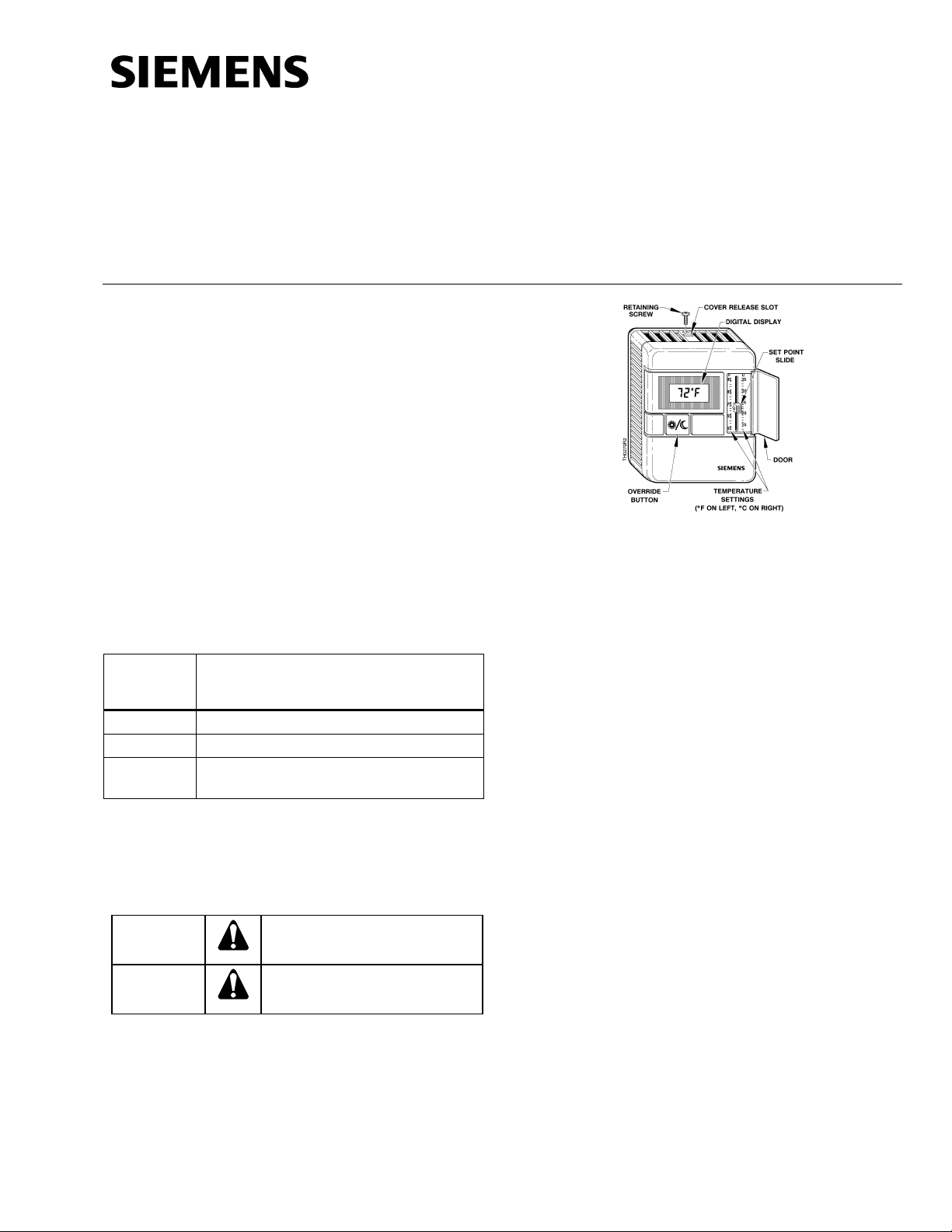
Figure 1. Room Temperature Sensor (Showing All
Optional Features).
Required Tools
• Phillips size 1 or 2 screwdriver
• 1/16-inch (1.57 mm) Allen wrench, if needed
(192-632, package of 5)
• Small, flat-blade screwdriver
• Medium, flat-blade screwdriver
• Medium-duty electric drill
• 3/16-inch (4.8 mm) drill bit
• One-inch (25 mm) hole saw
• Small level
• Tape measure
• Marker or pencil
Expected Installation Time
30 minutes
Prerequisites
• Review these instructions before beginning.
• Installed: appropriate field wiring (standard
four-conductor or six-conductor room sensor
cables, plenum or non-plenum as required),
within the maximum wiring run length for the
individual field panel or equipment controller.
NOTE: All wiring must comply with National
Electric Code (NEC) and local
regulations.
Page 1 of 5
Page 2

Document No. 540-743
Installation Instructions
September 10, 2009
Accessories
Review Table 2 to verify that you have the appropriate mounting hardware.
For retrofit installations, normally follow the method used by the pre-existing device. You may need to replace
existing mounting hardware. Always mount the sensor vertically.
Table 2. Accessories.
P/N Description Used For Reference
PTX6.4SPS Sensor Power Supply
Module
182-621 Gym Guard Kit, desert
beige
182-621E Gym Guard Kit, satin
chrome
182-683 Metal (and Wood) Stud
Mounting Bracket
(pkg. 5)
182-685 Spring Clips: Finished
Drywall Mounting Kit
(10 pack)
192-506 Electrical Box Adapter
Plate Assembly Kit
(pkg. 5)
192-860 Finish Plate Kit 1 Gang 1
Sensor; stainless steel
536-666 Mounting Strap standard light switch plate (field-supplied) to mount
544-782* Single Adapter Base
Mounting Kit
544-783* Double Adapter Base
Mounting Kit
544-784 Non-conduit Rough-in
Kit, Double
544-785* Extender Ring Kit exterior brick or cement-type walls; fits to back of
544-800 Universal Adapter Kit retrofitting a previous horizontal installation to a
981-344 Electrical Box Cover
Plate Kit
— Various finish plates double-sensor, low-cost mounting for a variety of
* Product number suffixes indicate color: A = desert beige; B = white (e.g., 544-782B)
MBC/RBC applications with digital display 545-422
gyms and similar environments requiring a guard.
(Incompatible with adapter bases and the extender
155-222P25
(TB 193)
ring.)
See above. 155-222P25
(TB 193)
single-sensor rough-in installations. Kit includes
129-057
locator.
drywall mounting. 129-073
electrical boxes mounted flush with the wall and for
Figure 8
gyms and similar environments requiring a guard.
(Also see 544-782.)
single-sensor, low-cost mounting. Plate is 3.7 × 5.1
inches (9.5 × 12.9 cm)
155-252P25
(TB 238)
540-040
sensor on 2 × 4 electrical box
2 × 4 boxes, all single sensor installations on walls
540-237
Figure 8
with oversized holes, paint lines, etc., that need to be
covered, and on exterior brick/cement-type walls. Kit
includes Electrical Box Adapter Plate Assembly
(192-495. Adapter base is 3-1/2 × 5 inches
(8.8 × 12.7 cm).
4 × 6 boxes and all double sensor installations on
Figure 8
walls with oversized holes, paint lines, etc., that need
to be covered, and on exterior brick/cement-type
walls. Kit includes two mounting plates (192-720).
Adapter base is 5 × 7 inches (12.7 × 18 cm).
double-sensor non-conduit rough-in installations. Kit
540-784
includes locator.
—
sensor base plate
Figure 8
vertical one, or when the screw spacing does not fit
the electrical box adapter plate. Kit includes multislotted adapter plate.
2 × 4 box rough-ins. Kit includes locator and
—
connector.
155-252P25
applications.
(TB 238)
Page 2 of 5 Siemens Building Technologies, Inc.
Page 3

Mounting Information
Locate the sensor:
• according to design specifications and local
regulations.
• where the air circulates around it freely (not
in recessed areas or behind doors).
• allowing a minimum of 4 inches (100 mm)
free space above and below for proper
airflow, the front cover removal tool, and the
computer communication cable.
• away from drafts caused by doors, windows,
outside walls, air registers, pipes, return air
plenums, etc.
• away from heat sources such as strong
lights, fireplaces, direct sunlight, etc.
• on an inside wall (preferably), about 5 feet
(1.5 m) above the finished floor.
Document No. 540-743
Installation Instructions
September 10, 2009
NOTE: While not recommended, if you must mount
the sensor on exterior brick or cement-type
walls, see Accessories.
Drywall Mounting (No Rough-in),
Typical
1. Mark the center (cable) hole and the mounting
hole locations using the sensor base plate as a
template. See Figure 2.
CAUTION:
For drywall mounting, only use the top
and bottom holes.
2. Drill two 3/16-inch (4.8 mm) mounting holes.
3. Cut a 1-inch (25 mm) center hole with a hole
saw.
4. If using screws to attach the sensor, insert two
plastic wall anchors.
5. Pull about three inches (75 mm) of the cable
through the mounting hardware in the order
shown. See Figure 2.
Figure 2. Drywall Mounting (No Rough-in), Typical.
6. Mount the sensor base plate on the wall, noting
the UP arrow on the stabilizer plate:
a. Install either the two mounting screws
provided, the drive rivets provided, or
spring clips, but do not tighten.
CAUTION:
Pounding too hard or over-tightening may
cause the sensor base plate to crack or
bend.
b. Level the sensor base plate for
appearance.
c. Tighten the two mounting screws to the
sensor base plate.
7. Cut the cable, leaving about 3 inches (75 mm)
on the sensor side of the drywall.
CAUTION:
For retrofits: Before cutting the cable,
make sure it is disconnected from the
UC/MBC/RBC.
8. Unplug the terminal block from the back of the
printed circuit board (PCB) and terminate the
cable wires at the sensor terminal block. For sixposition terminal blocks, see Figure 3. For fourposition terminal blocks, see Figure 4. Also see
Figure 5 (MBC/RBC) or Figure 6 (UC). Reinstall
the terminal block.
Siemens Building Technologies, Inc. Page 3 of 5
Page 4

Document No. 540-743
Installation Instructions
September 10, 2009
Figure 3. Terminating to Six-position Terminal Block
(with Setpoint Switch).
Terminating the Cable Wires
NOTE: 1. All connections for one sensor must be
terminated in the same cabinet, whether
MBC, RBC, MEC or UC.
2. Unitary Controller installations: On the
UC Input/Output Card, place the
universal inputs jumper in the RTD
position.
Figure 4. Terminating to Four-position Terminal Block
(No Setpoint Switch).
9. Feed the extra cable back through the hole in
the rubber insulator.
10. Snap the sensor front to the sensor base plate
by first hooking the sensor front to the bottom
latches, and then pushing the top of the sensor
front into place until it latches.
11. Tighten the sensor front retaining screw. See
Figure 2.
12. Terminate the other end of the wires either (a) at
the MBC/RBC module terminal block(s)
(Figure 5) or (b) at the appropriate UC terminal
blocks (Figure 6.)
The installation is now complete.
Figure 5. MBC/RBC Wiring Example. (Wiring to
Full-featured Sensor 544-780).
Figure 6. UC Wiring. (Wiring to Full-featured
Sensor 544-780).
Page 4 of 5 Siemens Building Technologies, Inc.
Page 5

Document No. 540-743
Installation Instructions
September 10, 2009
TERMINAL BLOCK
6 SETPT*
5 COM2*
4 RTD
3 COM 1
2 LCDPR*
1 OVRRD*
MEC0045R1
SENSOR
SIG 2
COM 2
SIG 1
COM 1
24 VDC+
DI
DI1
DI2
DI3
DI4
49
50
51
52
SHIELD
AI17
AI18
AI19
AI20
9
53
54
55
56
+
+
+
+
-
DI5
10
11
DI6
12
13
DI7
14
15
DI8
16
+
24 VDC
SENSOR
SUPPLY
41
AI21
42
43
AI22
44
45
AI23
46
47
AI24
48
+
+
+
+
-
1
2
3
4
5
6
7
8
33
34
35
36
37
38
39
40
4. Pull the cable through the required mounting
hardware in the order shown.
* Optional feature
NOTE: 1. Some terminal blocks have only four terminal points.
2. Not all wires are used with all sensor models.
3. COM2 is the return signal path for the setpoint option.
4. Wiring configuration is only an example and can differ
depending on application.
Figure 7. MEC Wiring. (Wiring to Full-featured
Sensor 544-780).
Figure 8. Electrical Box and Rough-in Mounting,
Typical.
5. Install the two sensor mounting screws provided
but do not tighten.
Electrical Box and Rough-in
Mounting, Typical
1. If a locator is attached to the rough-in device,
remove the locator by removing the two screws
and lightly rocking the locator to pull it free.
2. Untie the twist tie and pull about three inches
(75 mm) of the sensor cable into the space.
3. If you have a single-sensor electrical box, install
the electrical box adapter plate. See Figure 8.
If you have a double-sensor electrical box,
install the required mounting plate(s).
If you use a universal adapter kit for a retrofit
6. Mount the sensor base plate on the wall, noting
the "UP" arrow on the stabilizer plate:
a. Level the sensor base plate for appearance
only.
b. Tighten the two mounting screws to the
sensor base plate.
CAUTION:
Over-tightening may cause the sensor
base plate to crack or bend.
7. Continue with Drywall Mounting (No Rough-in,
Typical), Steps 7 through 13.
The installation is now complete.
job, install the multi-slotted plate in place of the
electrical box adapter plate. See Figure 8.
Information in this publication is based on current specifications. The company reserves the right to make changes in specifications and
models as design improvements are introduced. Product or company names mentioned herein may be the trademarks of their respective
owners.
© 2009 Siemens Building Technologies, Inc.
Siemens Building Technologies, Inc.
Industry Sector
1000 Deerfield Parkway
Buffalo Grove, IL 60089-4513
Your feedback is important to us. If you have
comments about this document, please send them
to SBT_technical.editor.us.sbt@siemens.com
Document No. 540-743
Printed in the U.S.A.
Page 5 of 5
U.S.A.
 Loading...