

Sico 4182 Installation Manual
EUROBED
(MODEL No. 4182, 5682, 6387)
®
BEFORE YOU BEGIN...
WARNING
This bed must be securely anchored to the
wall or floor. Failure to follow instructions
may cause the bed and cabinet to tip over,
which could cause serious injury.
NOTICE: It takes two people to safely assemble
the system - do not try to do it by yourself.
Please read and understand the instructions before
you start to assemble.
If you have any problems when installing,
contact SICO Customer Service at
1-800-328-6138
and 24/7 EUROBED
®
(Model No. 5690T, 5695T, 6395T)
INSTALLATION
INSTRUCTIONS
Tools Required
-Phillips and flat blade screwdrivers
- Electric drill, 1/4” or 3/8”
- Drill bits: 1/8”; 3/16”; 1-3/8” (not required if using SICO
recess). A 1” bit may also be required (see page 9).
- Rotary hammer drill (if attaching to floor)
- Masonry bit (if attaching to masonry floor or wall); size of
bit depends on floor type - refer to pages 8-10
- Screw-anchor setting tool (if attaching to soft concrete
floor)
- Carpenter’s Level
- Tape Measure
- Stud finder (preferably an electronic type)
- Hammer
- Ratchet wrench, 9/16” standard and 3/4” deep socket.
Printed in the USA (02-05) SICO is a registered trademark and EUROBED®is a trademark of SICO IncorporatedPart No. 104595 Rev F
SPECIFICATION SHEET
EUROBED
®
2
24/7
®
EUROBED
SPECIFICATION SHEET
3
WARNING!
The counterbalancing of the EUROBED®is
WARNING
If you fail to properly secure
the recess to the wall or floor,
it could be pulled down and
serious injury could result.
If your wall construction is such that the system cannot or should not be attached to
the wall (see step 1 on page 9), follow the floor mounting instructions on page 9
through 12 instead.
Hardware is included with the EUROBED®for attaching to most wall constructions.
Follow the instructions on pages 6 to 8 to assure proper installation.
Hardware is not included for floor attachment.
supported by the weight of the cabinet
plus the attachment of the cabinets to the
wall. It is therefore very important that the
recess / cabinets system be anchored
securely to the wall, as high off the floor
as possible. Use the SICO wall-mounting
fixture provided with the bed.
Wall attachment
required here.
Custom cabinets must be strong enough to
transfer the counterbalancing requirements
from the bed support to the rear wall.
The cabinet and recess sides must be at least 3/4” thick, of wood or woodlike material.
Drywall is not an acceptable material for securing the mounting plates of the bed
mechanism.
4
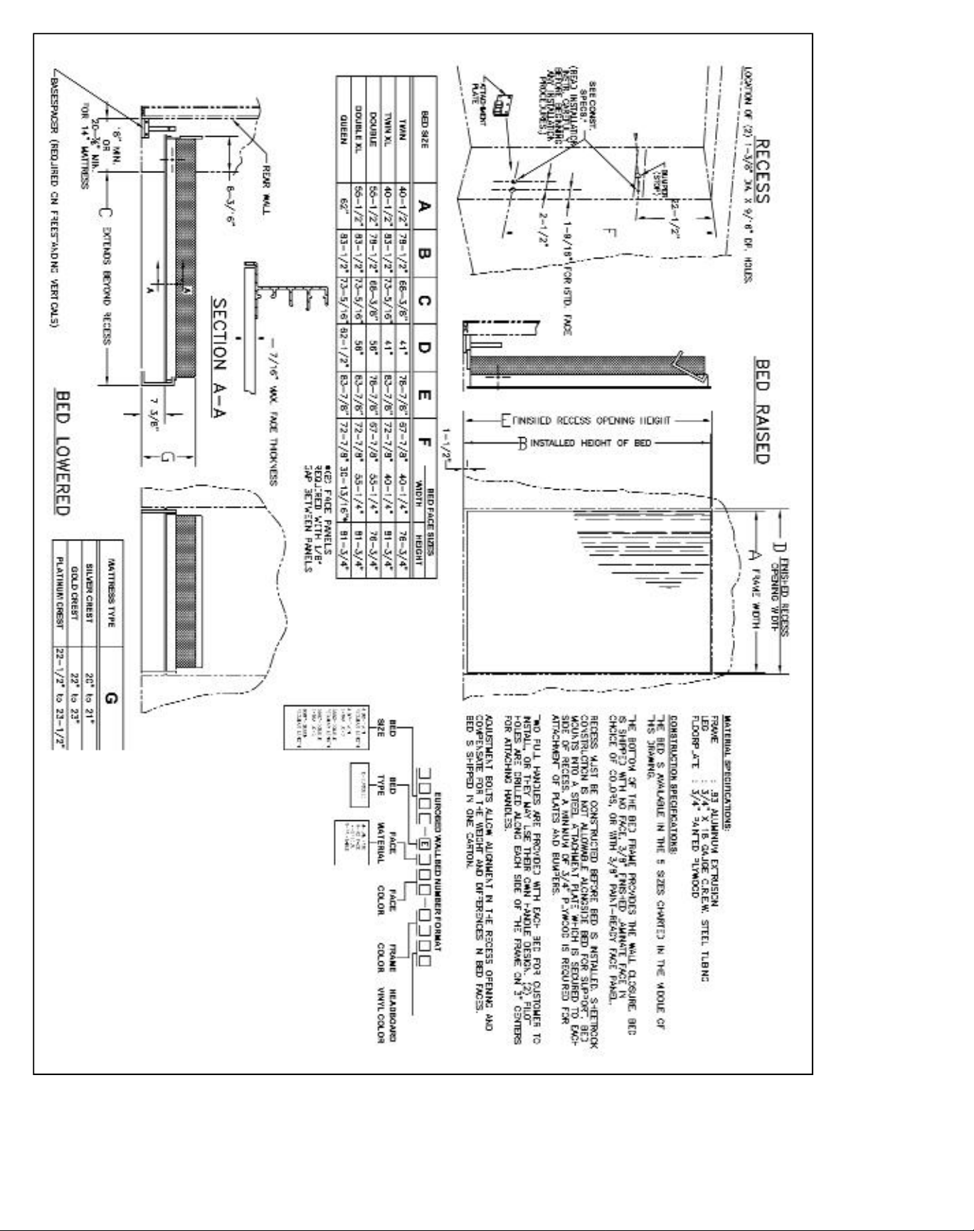
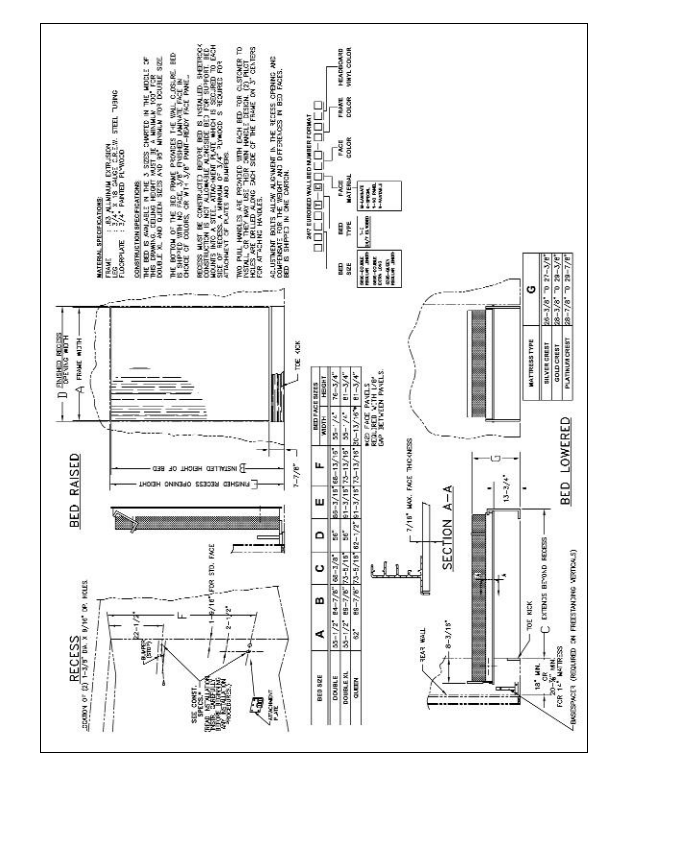
GENERAL INFORMATION
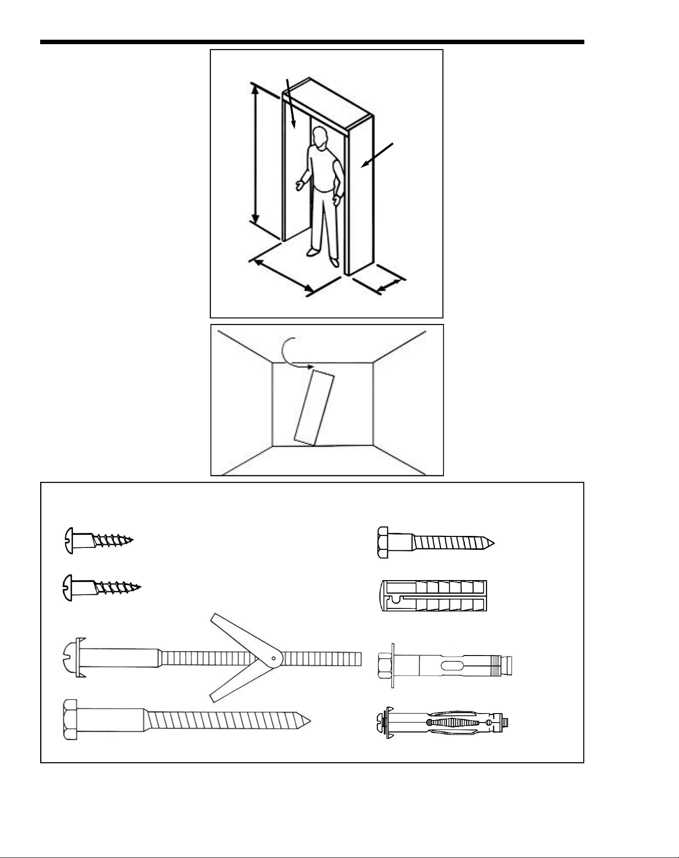
IMPORTANT: Before you start
to install the bed, verify the size
of opening required:
Bed
Size
Twin 78-7/8” -- 41”
Twin XL 83-7/8” -- 41”
Double 78-7/8” 86-3/16” 56”
Double XL 83-7/8” 91-3/16” 56”
Queen 83-7/8” 91-3/16” 62-1/2”
Opening
Height
EUROBED
Opening
Height
®
24/7
Opening
Width
If the bed is being installed in a
SICO EUROBED®Recess
(according to instructions
#108450-04), assemble the
recess and secure it to the wall,
then skip to page 14.
If the bed is being installed in a
custom cabinet, begin on page 6.
IMPORTANT: When installing
the EUROBED®make sure
the ceiling clearance is
greater than 93”. For the
EUROBED®24/7 regular
length bed make sure the ceiling height is 95” or greater.
For the queen and extra long
bed the ceiling height should
be 100” or greater.
Opening
Height
Opening
Width
Right
Hand Side
Be sure there is
enough clearance
Left
Hand
Side
Minimum
Depth
of 18”
If anything is missing or if
you have any questions at
installation, contact SICO
®
Customer Service at
1-800-238-6138.
NOTE: The minimum recess
depth is 18” for a standard
mattress thickness of 10-1/2”;
add 1” to the minimum recess
depth for each additional 1”
of mattress thickness.
For thicker bed faces: the
standard bed face is 3/8”. For
thicker bed faces (raised
panel, trim, etc.), mount flush
with front of recess, add the
difference between the actual
bed face thickness and 3/8”
to the minimum depth.
IMPORTANT
For safety, you must use the correct fasteners when anchoring the system to the wall or floor.
Refer to this illustration when assembling.
#12 x 1” wood screw, Part No. 118312
#14 x 1” wood screw,
Part No. 103745
3/8 x 6” round-head
toggle bolt
1/2 x 5” hex-head lag screw
5
5/16 x 2” lag screw, Part No. 100977
5/16” lag shield (for concrete walls),
Part No. 100975
1/2 x 3” expansion anchor
1/4 x 2-1/2” hollow-wall anchor,
Part No. 100976
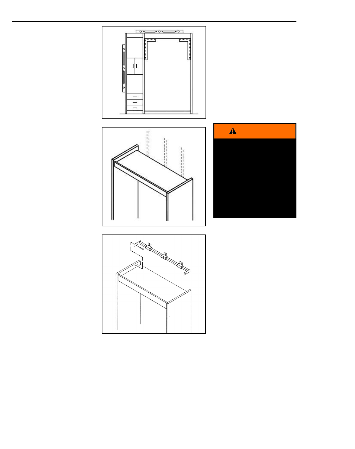
SECURE RECESS TO WALL
1. Recheck that the unit is level,
plumb, and square. Adjust the
leveling feet as necessary.
2. Determine the exact location of
all wall studs behind the
recess. Use a stud finder
(preferably the electronic type).
The counterbalancing of a
EUROBED® is supported by the
weight of the header and cabinets
plus their attachment to the wall. It
is therefore very important that the
header/cabinet system be
anchored securely to the wall, as
high off the floor as possible.
If the system cannot or should not
be attached to the wall (see step 1
on page 9), follow the floormounting instructions on pages 9
through 11 instead.
WARNING
Failure to securely
anchor the system
according to instructions can allow it to
tip over when the
bed is operated which could cause
serious injury.
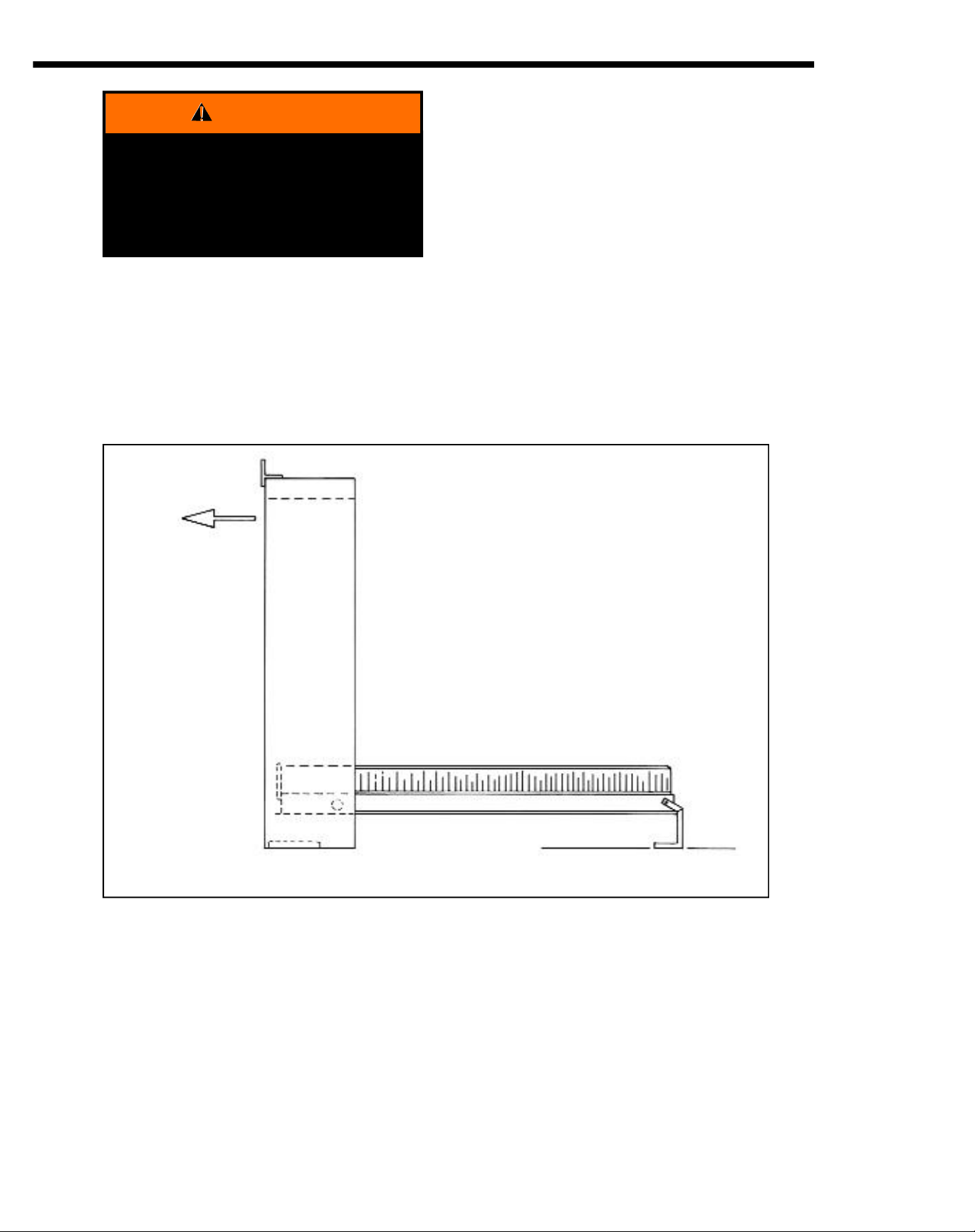
3. Attach the SICO®wall-mounting
fixture to the bed-recess verticals:
a. Hold the fixture flush with
the top and back edges of
the verticals, then push it
straight back against the
wall.
b. Hold the fixture in this posi-
tion, and mark the location
of the screw holes.
c. Drill 1/8” dia. pilot holes in
both verticals, 3/4” deep.
d. Attach the fixture to the
inside of the verticals with
four screws (part number
103745 ) at each end.
If the fixture must be moved more
than 3/4” back beyond the edge of
th vertical (because the wall is very
uneven or out of plumb), contact
the factory before installing.
The wood screws (Part No.
103745) supplied for attaching the
SICO wall-mounting fixture and the
EUROBED®mechanism plate are
intended for verticals which are 1”
or more thick. If your verticals are
less then 1” thick, install washers
under the screw heads as necessary.
6
 Loading...