

Page 1
DE
EN
MLG/XLG
Modular Light Grid
QUICKSTART
Page 2

Quickstart
Modulares Lichtgitter MLG/XLG
2 © SICK AG • Advanced Industrial Sensors • Irrtümer und Änderungen vorbehalten •
8014221
Page 3
Quickstart
Modulares Lichtgitter MLG/XLG
Sicherheitshinweise
VORSICHT!
– Zusätzlich zum Quickstart gibt es die ausführli-
chen Betriebsanleitungen für die modularen
Lichtgitter MLG/XLG. Das Quickstart ersetzt die
Betriebsanleitung nicht. Die Betriebsanleitungen
können Sie über das Internet "www.mysick.com"
herunterladen.
– Alle Arbeiten wie z.B. elektrischer Anschluss,
Montage und Inbetriebnahme dürfen nur von
Fachkräften bzw. Elektrofachkräften durchgeführt
werden.
ACHTUNG!
– Lichtgitter nur mit einer geschützten Niederspan-
nung und einer sicheren elektrischen Isolierung
der Schutzklasse III betreiben.
– Verdrahtungsarbeiten nur im spannungslosen
Zustand durchführen.
– Leitungsverbindungen nur im spannungslosen
Zustand verbinden und trennen.
– Durch Umspiegelungen, Verunreinigungen, Blen-
dungen, Ausfall einzelner Komponenten, elektromagnetische Störaussendungen anderer Geräte
können Fehlschaltungen auftreten.
Haftungsbeschränkung
Der Hersteller übernimmt keine Haftung für Schäden aufgrund:
Nichtbeachtung des Quickstarts
Bestimmungswidriger Verwendung
Einsatzes von nicht ausgebildetem Personal
Eigenmächtiger Umbauten
Technischer Veränderungen
Verwendung nicht zugelassener Ersatz- und Verschleißteile.
© SICK AG • Advanced Industrial Sensors • Irrtümer und Änderungen vorbehalten • 3
8014221
Page 4
Quickstart
Modulares Lichtgitter MLG/XLG
Bestimmungsgemäße Verwendung
Die Lichtgitter MLG und XLG sind optoelektronische Sensoren, be-
stehend aus einem Sender (MLG S/XLG S) und einem Empfänger
(MLG E/XLG S).
Die Lichtgitter sind ausschließlich zum optischen und berührungslosen Erfassen von Sachen, Tieren und Personen vorgesehen.
Bestimmungswidrige Verwendung
Die Lichtgitter MLG und XLG sind keine Sicherheitsbauteile gemäß
der EG-Maschinenrichtlinie (2006/42/EG).
Die Lichtgitter MLG und XLG dürfen nicht für Anwendungen im Per-
sonenschutz eingesetzt werden.
Die Lichtgitter MLG und XLG sind keine Sicherheitslichtgitter. Die
Lichtgitter MLG und XLG dürfen nicht als Sicherheitsvorrichtung
eingesetzt werden, um Personen, deren Hände oder andere Körperteile vor dem Zugang zu Gefahrbereichen zu schützen.
Die Lichtgitter MLG und XLG dürfen nicht in explosionsgefährdeten
Bereichen eingesetzt werden.
An den Lichtgittern MLG und XLG dürfen keine Änderungen oder
Umbauten durchgeführt werden.
Alle unter der bestimmungsgemäßen Verwendung nicht beschriebenen Verwendungen sind verboten.
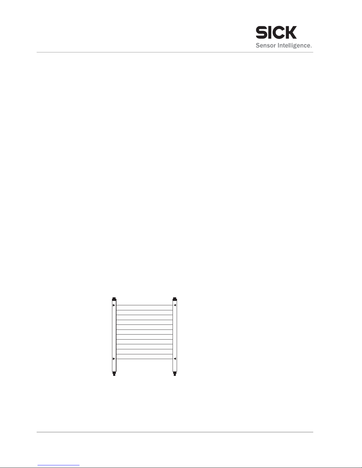
Aufbau und Anzeigeelemente
SICK00025
MLG S
XLG E
MLG E
XLG S
4 © SICK AG • Advanced Industrial Sensors • Irrtümer und Änderungen vorbehalten •
8014221
Page 5

Quickstart
Modulares Lichtgitter MLG/XLG
© SICK AG • Advanced Industrial Sensors • Irrtümer und Änderungen vorbehalten • 5
8014221
LEDs
LED Beschreibung
Grüne LED Versorgungsspannung an.
Gelbe LED
leuchtet
dauerhaft
Sender und Empfänger sind korrekt zueinander ausgerichtet und der Lichtweg ist nicht unterbrochen.
Gelbe LED
blinkt
Sender und Empfänger sind nicht korrekt zueinan-
der ausgerichtet.
Verschmutzung festgestellt.
Zulässige Reichweite überschritten.
Gelbe LED aus Lichtweg unterbrochen.
Sender und Empfänger sind nicht korrekt zueinan-
der ausgerichtet.
Rote LED
Störung: → Siehe Betriebsanleitung, Kapitel "Störungsbehebung".
7-Segmentanzeige
7-Segementanzeige
Beschreibung
H Blocked Beams Hold (BBH) ist aktiv.
L Empfindlichkeit einlernen (Teach-in) ist aktiv.
P Parametermode ist aktiv.
S Stand-by ist aktiv.
E1, E2, E9
Störung: → Siehe Betriebsanleitung, Kapitel "Störungsbehebung".
Montage
Betriebsreichweite beachten.
Empfänger und Sender mit derselben Orientierung montieren.
Empfänger und Sender auf gleicher Höhe montieren.
1. Empfänger fest montieren.
2. Elektrischen Anschluss durchführen.
3. Sender zum Empfänger ausrichten. Bei korrekter Ausrichtung
leuchtet am Empfänger die gelbe LED dauerhaft.
4. Sender fest montieren.
Elektrischer Anschluss
Am Sender und Empfänger befindet sich ein Aufkleber mit dem An-
schlussschema und Angaben zu den Eingängen und Ausgängen.
Elektrischen Anschluss gemäß dem Anschlussschema durchführen.
Page 6

Quickstart
Modulares Lichtgitter MLG/XLG
6 © SICK AG • Advanced Industrial Sensors • Irrtümer und Änderungen vorbehalten •
8014221
Inbetriebnahme
Empfindlichkeit
einlernen (Teach-in)
Bei der Inbetriebnahme und ggf. in regelmäßigen Abständen muss
für jeden Empfangskanal des Lichtgitters die optimale Empfindlichkeit eingelernt werden. Dieses Verfahren wird auch als Teach-in
bezeichnet.
1. Zwischen Sender und Empfänger darf sich kein Objekt befinden.
Der Lichtweg muss frei sein.
2. Stromversorgung für das Lichtgitter einschalten. Die grünen LEDs
am Empfänger und am Sender müssen leuchten.
3. Je nach Lichtgittertyp:
MLG PROFIBUS DP und MLG CANopen: Teach-in-Mode über
Schnittstelle aktivieren und wieder deaktivieren.
MLG Programmierbar: Einlernprozess über das Konfigura-
tionsprogramm MLGsetup durchführen.
MLG/XLG mit Eingang: Einlernprozess über Eingang "In1
(Teach-in)" aktivieren. Nach 20 ms das Signal deaktivieren.
Sonstige MLGs/XLGs: Der Einlernprozess startet automatisch
nach dem Einschalten der Versorgungsspannung.
Während des Einlernprozesses wird in der 7-Segmentanzeige am
Empfänger ein "L" angezeigt.
4. Die gelbe LED am Empfänger leuchtet. Das Lichtgitter ist betriebsbereit.
Technische Daten
Betriebsreichweite Je nach Lichtgittertyp: 5 m oder 8,5 m
Versorgungsspannung UV 18 … 30 V DC
Stromaufnahme bei
24 V DC ohne Last
Sender: < 140 mA + 2 mA/Strahl
Empfänger: < 100 mA + 3 mA/Strahl
Schutzklasse III
Schutzschaltungen Anschlüsse verpolsicher
Ausgänge kurzschlussgeschützt
Störimpulsunterdrückung
Umgebungstemperaturbereich
–25 … +55 °C
Schutzart IP 65
Service
→ Siehe Rückseite.
Page 7

Quickstart
MLG/XLG modular light grid
Safety notes
CAUTION!
– There are detailed operating instructions in addi-
tion to the quickstart for the MLG/XLG modular
light grid. The quickstart is not intended to replace the operating instructions. Instruction
manuals can be downloaded via the internet at
“www.mysick.com”.
– All work such as electrical connection, mounting
and commissioning may only be performed by
skilled persons or skilled electricians.
NOTICE!
– Only operate the light grid using a protected low
voltage and safe electrical insulation according to
protection class III.
– Only carry out wiring work in a de-energized state.
– Only connect and disconnect cable connections
in a de-energized state.
– Reflections, impurities, dazzling, failure of indi-
vidual components and electromagnetic interference from other devices can cause incorrect
switching.
Limitation of liability
The manufacturer accepts no liability for damage caused by:
failing to observe the quickstart
incorrect use
use by untrained personnel
unauthorized alterations
technical modifications
use of unauthorized spare and wear parts.
© SICK AG • Advanced Industrial Sensors • Subject to change without notice • 7
8014221
Page 8

Quickstart
MLG/XLG modular light grid
Correct use
The MLG and XLG light grids are opto-electronic sensors consisting of
a sender (MLG S/XLG S) and a receiver (MLG E/XLG S).
The light grids are solely intended for the optical and non-contact
detection of objects, animals and people.
Improper use
The MLG and XLG light grids are not safety components in accor-
dance with the EC Machinery Directive (2006/42/EC).
The MLG and XLG light grids may not be used for personal protection
applications.
The MLG and XLG light grids are not safety light grids. The MLG and
XLG light grids may not be used as a safety device access protection
for persons, their hands or other bodily parts to hazardous areas.
The MLG and XLG light grids may not be used in potentially explosive
atmospheres.
No modifications or alterations may be made on the MLG and XLG
light grids.
All uses not described under correct use are prohibited.
Structure and status indicators
SICK00025
MLG S
XLG E
MLG E
XLG S
8 © SICK AG • Advanced Industrial Sensors • Subject to change without notice •
8014221
Page 9

Quickstart
MLG/XLG modular light grid
© SICK AG • Advanced Industrial Sensors • Subject to change without notice • 9
8014221
LEDs
LED Description
Green LED Supply voltage on.
Yellow LED
illuminates
permanently
Sender and receiver are aligned correctly to each other
and the light path is not interrupted.
Yellow LED
flashes
Sender and receiver are not correctly aligned to
each other.
Contamination found.
Permissible scanning range exceeded.
Yellow LED off Light path interrupted.
Sender and receiver are not correctly aligned to
each other.
Red LED
Malfunction: → See operating instructions, chapter
"Troubleshooting".
7-segment display
7-segment
display
Description
H Blocked Beams Hold (BBH) is active.
L Teach-in sensitivity is active.
P Parameterization mode is active.
S Stand-by is active.
E1, E2, E9
Malfunction: → See operating instructions, chapter
“Troubleshooting”.
Mounting
Observe operating range.
Mount the receiver and sender at the same orientation.
Mount the receiver and sender at the same height.
1. Mount the receiver in a fixed position.
2. Establish electrical connection.
3. Align the sender to the receiver. When aligned correctly, the
yellow LED on the receiver illuminates permanently.
4. Mount the sender in a fixed position.
Electrical connection
A label with a connection example and input and output specifica-
tions is located on the sender and the receiver. Establish electrical
connection according to the connection example.
Page 10

Quickstart
MLG/XLG modular light grid
10 © SICK AG • Advanced Industrial Sensors • Subject to change without notice •
8014221
Commissioning
Teach-in sensitivity During commissioning and at regular intervals, as necessary, the
optimum sensitivity must be taught in for each receiving beam path
on the light grid. This procedure is called teach-in.
1. No objects should be between the sender and the receiver. The
light path must be clear.
2. Switch on the power supply for the light grid. The green LEDs on
the receiver and the sender should illuminate.
3. Depending on the type of light grid:
MLG PROFIBUS DP and MLG CANopen: Activate and deacti-
vate teach-in mode via the interface.
MLG programmable: Use the configuration program
MLGsetup to teach-in.
MLG/XLG with input: Activate teach-in via input “In1 (Teach-
in)”. Deactivate the signal after 20 ms.
Other MLGs/XLGs: Teach-in starts automatically after the
supply voltage is switched on.
During teach-in, “L” will be displayed on the 7-segment display on
the receiver.
4. The yellow LED on the receiver illuminates. The light grid is operational.
Technical specifications
Operating range Depending on the type of light grid: 5 m or 8.5 m
Supply voltage UV 18 … 30 V DC
Current consumption
at U
V
= 24 V without load
Sender: < 140 mA + 2 mA/beam
Receiver: < 100 mA + 3 mA/beam
Protection class III
Protective circuits Reverse polarity protected connections
Short-circuit protected outputs
Interference pulse suppression
Ambient temperature
range
–25 … +55°C
Enclosure rating IP 65
Service
→ See reverse.
Page 11

Quickstart
MLG/XLG modular light grid
© SICK AG • Advanced Industrial Sensors • Subject to change without notice • 11
8014221
Page 12

8014221/2011-05-01 ∙ (2011-05) ∙ A5 sw int36
Australia
Phone +61 3 9497 4100
1800 33 48 02 – tollfree
E-Mail sales@sick.com.au
Belgium/Luxembourg
Phone +32 (0)2 466 55 66
E-Mail info@sick.be
Brasil
Phone +55 11 3215-4900
E-Mail sac@sick.com.br
Ceská Republika
Phone +420 2 57 91 18 50
E-Mail sick@sick.cz
China
Phone +852-2763 6966
E-Mail ghk@sick.com.hk
Danmark
Phone +45 45 82 64 00
E-Mail sick@sick.dk
Deutschland
Phone +49 211 5301-301
E-Mail kundenservice@sick.de
España
Phone +34 93 480 31 00
E-Mail info@sick.es
France
Phone +33 1 64 62 35 00
E-Mail info@sick.fr
Great Britain
Phone +44 (0)1727 831121
E-Mail info@sick.co.uk
India
Phone +91–22–4033 8333
E-Mail info@sick-india.com
Israel
Phone +972-4-999-0590
E-Mail info@sick-sensors.com
Italia
Phone +39 02 27 43 41
E-Mail info@sick.it
Japan
Phone +81 (0)3 3358 1341
E-Mail support@sick.jp
Nederlands
Phone +31 (0)30 229 25 44
E-Mail info@sick.nl
Norge
Phone +47 67 81 50 00
E-Mail austefjord@sick.no
Österreich
Phone +43 (0)22 36 62 28 8-0
E-Mail office@sick.at
Polska
Phone +48 22 837 40 50
E-Mail info@sick.pl
Republic of Korea
Phone +82-2 786 6321/4
E-Mail info@sickkorea.net
Republika Slovenija
Phone +386 (0)1-47 69 990
E-Mail office@sick.si
România
Phone +40 356 171 120
E-Mail office@sick.ro
Russia
Phone +7 495 775 05 34
E-Mail info@sick-automation.ru
Schweiz
Phone +41 41 619 29 39
E-Mail contact@sick.ch
Singapore
Phone +65 6744 3732
E-Mail admin@sicksgp.com.sg
South Africa
Phone +27 11 472 3737
E-Mail info@sickautomation.co.za
Suomi
Phone +358-9-25 15 800
E-Mail sick@sick.fi
Sverige
Phone +46 10 110 10 00
E-Mail info@sick.se
Taiwan
Phone +886 2 2375-6288
E-Mail sales@sick.com.tw
Türkiye
Phone +90 216 528 50 00
E-Mail info@sick.com.tr
United Arab Emirates
Phone +971 4 8865 878
E-Mail info@sick.ae
USA/Canada/México
Phone +1(952) 941-6780
1800-325-7425 – tollfree
E-Mail info@sickusa.com
More representatives and
agencies at www.sick.com
SICK AG | Waldkirch | Germany | www.sick.com
 Loading...