

Page 1
WTL16 - WTS16 Bluetooth®
O P E R A T I N G I N S T R U C T I O N S
Page 2
WTL16 - WTS16 Bluetooth®
O P E R A T I N G I N S T R U C T I O N S
de
en
es
fr
it
ja
pt
ru
zh
Page 3

Described product
WTL16, WTS16 - Bluetooth®
Manufacturer
SICK AG
Erwin-Sick-Str. 1
79183 Waldkirch
Germany
Legal information
This work is protected by copyright. Any rights derived from the copyright shall be
reserved for SICK AG. Reproduction of this document or parts of this document is only
permissible within the limits of the legal determination of Copyright Law. Any modifica‐
tion, abridgment or translation of this document is prohibited without the express writ‐
ten permission of SICK AG.
The trademarks stated in this document are the property of their respective owner.
© SICK AG. All rights reserved.
Original document
This document is an original document of SICK AG.
2
8022692.10DR | SICK
Subject to change without notice
Page 4

Contents
CONTENTS
1 Safety information............................................................................ 4
1.1 General safety notes................................................................................ 4
1.2 Notes on UL approval............................................................................... 4
2 Intended use...................................................................................... 4
3 Operating and status indicators...................................................... 4
4 Mounting............................................................................................. 6
5 Electrical installation........................................................................ 6
6 Commissioning.................................................................................. 7
7 Troubleshooting................................................................................. 14
8 Disassembly and disposal............................................................... 15
9 Maintenance...................................................................................... 15
10 Approvals............................................................................................ 16
10.1 Bluetooth® approvals............................................................................... 16
11 Technical data.................................................................................... 17
11.1 Technical data........................................................................................... 17
11.2 Bluetooth technical data®....................................................................... 17
8022692.10DR | SICK
Subject to change without notice
3
Page 5
2006/42/EC
NO
SAFETY
1 SAFETY INFORMATION
1 Safety information
1.1 General safety notes
■
Read the operating instructions before commissioning.
■
specialists.
■
■
■
These operating instructions contain information required during the life cycle of
the sensor.
1.2 Notes on UL approval
Connection, mounting, and configuration may only be performed by trained
Not a safety component in accordance with the EU Machinery Directive.
When commissioning, protect the device from moisture and contamination.
The device must be supplied by a Class 2 source of supply.
UL Environmental Rating: Enclosure type 1
2 Intended use
The WTL16 Bluetooth®, WTS16 Bluetooth® is an opto-electronic photoelectric proxim‐
ity sensor (referred to as “sensor” in the following) for the optical, non-contact detection
of objects, animals, and persons. If the product is used for any other purpose or modi‐
fied in any way, any warranty claim against SICK AG shall become void.
The WTS16 is particularly suited to the detection of flat, glossy, contrast-rich, and
uneven objects.
3 Operating and status indicators
Photoelectric proximity sensor with background suppression.
4
8022692.10DR | SICK
Subject to change without notice
Page 6
20
Ø 12,9
Ø 4,1
39,9
55,4
45,5
5
42
29,9
6
3
6,5
15
27,8
7,7
7,8
7,2
35,5
4,1
16
8,3
55,7
5
4
89
16
18,5
3
2
1
6
7
20
M12
18
Ø 4,1
39,9
55,4
55,7
45,5
5
7
42
29,9
52,9
6
17,5
3
6,5
15
28
7,5
35,5
4,1
5
4
16
16 18,5
3
2
1
89
6
7
Ø 4,1
39,9
55,4
45,5
5
42
29,9
6
3
6,5
15
27,8
7,7
7,8
7,2
35,5
4,1
16
55,7
4
3
12,2
12,2
1
2
2
20
24,2
Ø 12,9
8,3
78
5
6
M12
12,2
12,2
4
3
1
2
2
17,5
Ø 4,1
7
39,9
55,4
55,7
45,5
5
29,9
52,9
6)
3
6,5
15
28
7,5
35,5
4,1
42
20
18
24,2
16
78
5
6
OPERATING AND STATUS INDICATORS 3
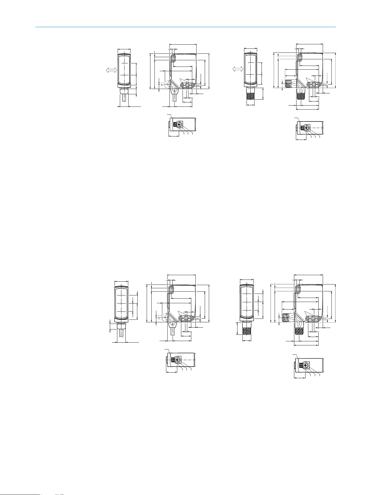
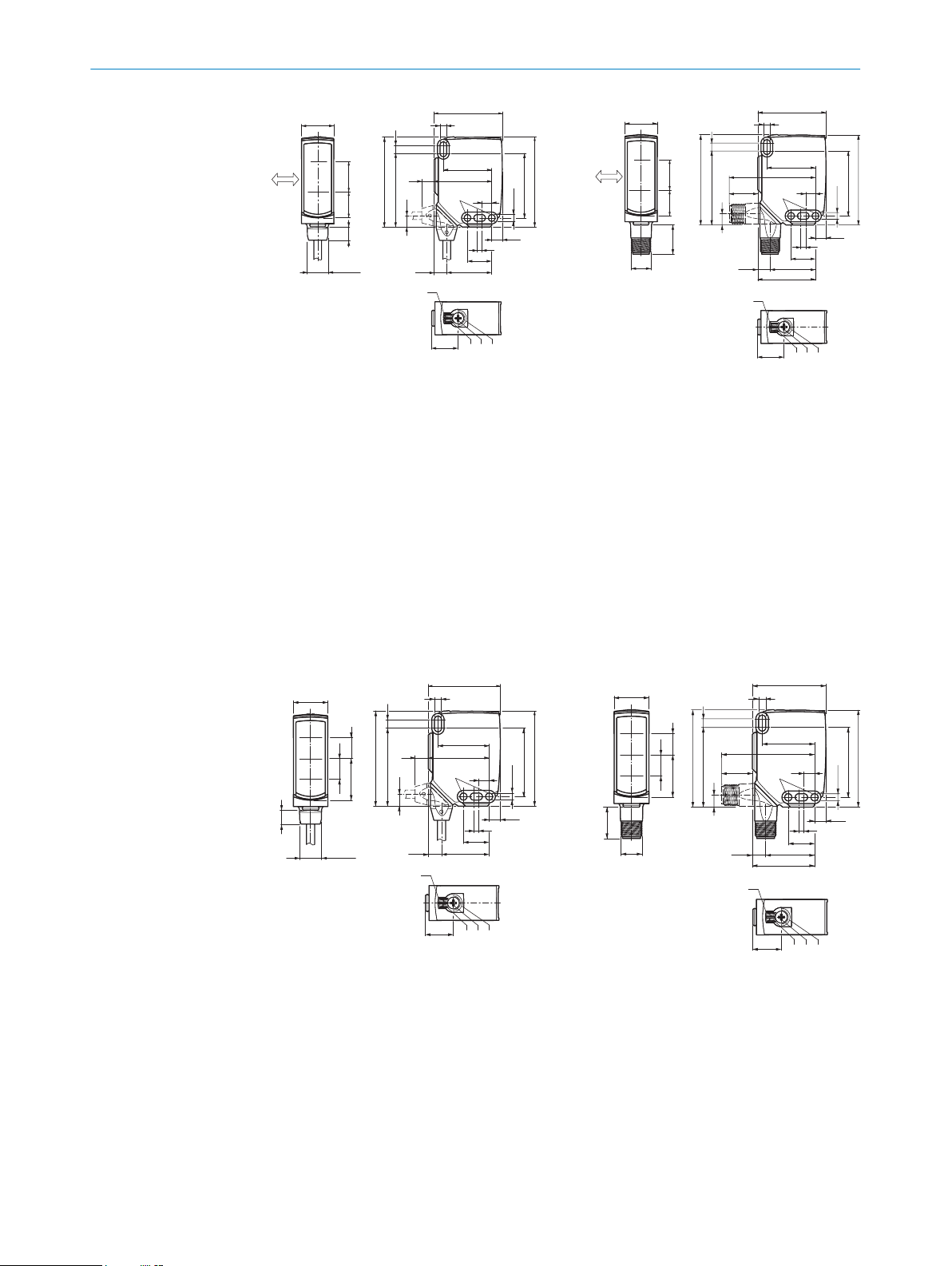
Figure 1: Dimensional drawing 1, WTL16
cable
Preferred direction of the target
1
object
Center of optical axis, sender
2
Center of optical axis, receiver
3
Fixing hole, Ø 4.1 mm
4
Connection
5
LED indicator green: Supply voltage
6
active
LED indicator yellow: Status of
7
received light beam
Press-turn element: Adjusting the
8
sensing range
BluePilot blue: Sensing range dis‐
9
play
Figure 2: Dimensional drawing 2, WTL16
male connector
Figure 3: Dimensional drawing 3, WTS16
cable
Center of optical axis, sender
1
Center of optical axis, receiver
2
Fixing hole, Ø 4.1 mm
3
Connection
4
LED indicator green: Supply voltage
5
active
LED indicator yellow: Status of
6
received light beam
Figure 4: Dimensional drawing 1, WTS16
male connector
5
8022692.10DR | SICK
Subject to change without notice
Page 7
1
2
4 3
1
2
4 3
1
2
4 3
4 MOUNTING
Press-turn element: Adjusting the
7
sensing range
BluePilot blue: Sensing range dis‐
8
play
4 Mounting
Mount the sensor using a suitable mounting bracket (see the SICK range of acces‐
sories).
Note the sensor’s maximum permissible tightening torque of < 1,3 Nm.
Note the preferred direction of the object relative to the sensor, see figure 1, figure 2
(only applies to WTL16).
5 Electrical installation
The sensors must be connected in a voltage-free state (UV = 0 V). The following informa‐
tion must be observed, depending on the connection type:
– Male connector connection: Note pin assignment.
– Cable: wire color
Only apply voltage/switch on the voltage supply (UV > 0 V) once all electrical connec‐
tions have been established.
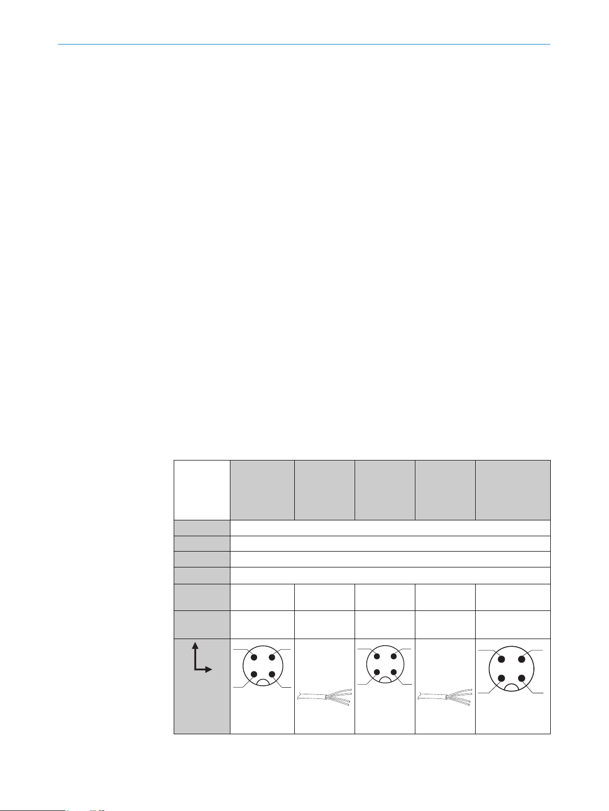
Explanations of the connection diagram (table 1, table 2).
MF (pin 2 configuration) = external input, teach-in, switching signal
QL1/C = switching output, IO-Link communication
DC: 10 ... 30 V DC
Table 1: DC
WTL16
WTS16
1 + (L+)
2 MF
3 - (M)
4 QL1/C
Default: MF
Default:
QL1/C
-24161xxxA00
-34161xxxA00
Q Q
Q Q
-1x161xxxA00-24162xxxA0
0
-34162xxxA0
0
Q Q www.sick.com
Q Q
1 = brn
2 = wht
3 = blu
4 = blk
-1x162xxxA00-2416xxxxA01A99
-3416xxxxA01A99
8020347
www.sick.com
8020347
1 = brn
2 = wht
3 = blu
4 = blk
AWG26
2
0.14 mm
0.14 mm
6
AWG26
2
8022692.10DR | SICK
Subject to change without notice
Page 8

Table 2: Push / pull
+ (L+)
Q
‒ (M)
+ (L+)
Q
‒ (M)
+ (L+)
Q
‒ (M)
+ (L+)
Q
‒ (M)
Q
Push-pull
(≤ 100 mA)
Q
Push-pull
(≤ 100 mA)
COMMISSIONING 6
6 Commissioning
Bluetooth® is switched on for initial commissioning. You can get SOPASair in the Google
PlayStore (Android) and in the App Store (iOS).
Operating system requirements: Android version 6.0, most current version of iOS.
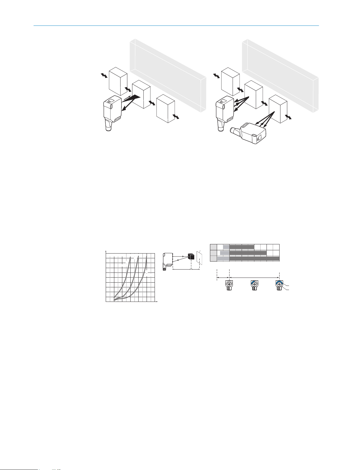
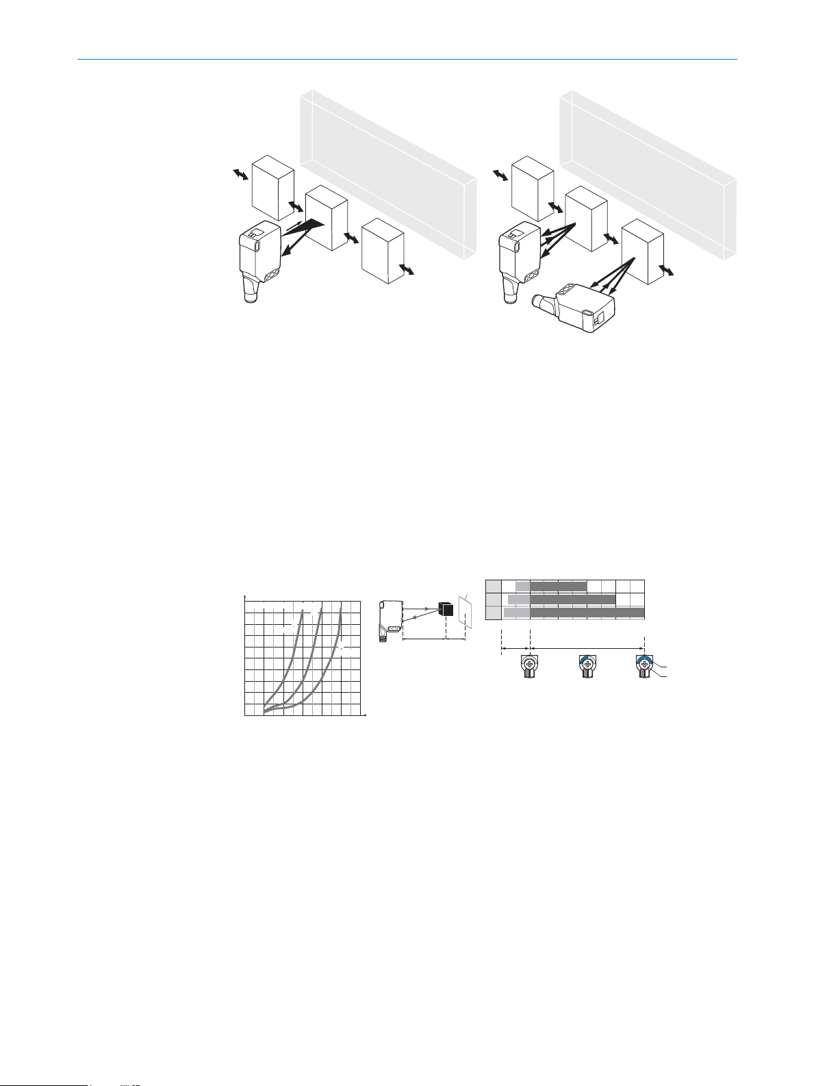
Alignment
WTL16 Bluetooth®, WTS16 Bluetooth®: Align sensor on object. Select the position so
that the red emitted light beam hits the center of the object. You must ensure that the
optical opening (front screen) of the sensor is completely clear [figure 5].
NOTE
For WTS16: If the objects are detected from above, we recommend installing the sen‐
sor at an angle in order to prevent total reflection by a reflective surface, see figure 11,
figure 14.
8022692.10DR | SICK
Subject to change without notice
7
Page 9
WTL16 WTS16
0
10
5
35
30
25
20
15
45
40
50
100
(3.94)
200
(7.87)
300
(11.81)
600
(23.62)
400
(15.75)
500
(19.69)
0
Distance in mm (inch)
1
2
3
WTL16P-xxxxx1xx
18%/90%
6%/90%
90%/90%
Minimum distance in mm (y) between the set sensing
range and background (white, 90%)
y
x
yx
white background (90%)
Example:
Sensing range on black, 6%,
x = 200 mm, y = 15 mm
100
(3.94)
200
(7.87)
Adjustment range
Distance in mm (inch)
A
300
(11.81)
400
(15.75)
500
(19.69)
0
1
2
3
50 300
25 400
10
500
BluePilot:
Sensing range
indicator (blue LED)
Teach-Turn
adjustment
A = Detection distance (depending on object remission)
100
100
100
6 COMMISSIONING
Figure 5: Alignment
Sensing range
Check the application conditions: Adjust the sensing range and distance to the object
or background and the remission capability of the object according to the correspond‐
ing diagram [see figure 6 and figure 7] (x = sensing range, y = minimum distance
between set sensing range and background (white 90%)). Remission: 6% = black 1,
18% = gray 2, 90% = white 3 (referring to standard white as per DIN 5033). We rec‐
ommend making the adjustments using an object with a low remission.
The minimum distance (= y) for background suppression can be determined from dia‐
gram [figure 61] as follows:
Example: x = 200 mm, y = 15 mm. That is, the background (white, 90%) is suppressed
at a distance of > 15 mm from the sensor.
Figure 6: Characteristic line 1, WTL16 Blue‐
tooth®-xxxxx1xx, red light
Sensing range on black, 6% remission
1
Sensing range on gray, 18% remission
2
Sensing range on white, 90% remission
3
8
8022692.10DR | SICK
Subject to change without notice
Page 10
0
20
10
60
50
40
30
80
70
90
200
(7.87)
400
(15.75)
600
(23.62)
1,000
(39.37)
800
(31.5)
0
1
2
3
WTS16P-xxxxx1xx
18%/90%
6%/90%
90%/90%
y
x
yx
Minimum distance in mm (y) between the set sensing
range and background (white, 90%)
white background (90%)
Example:
Sensing range on black, 6%,
x = 300 mm, y = 20 mm
Distance in mm (inch)
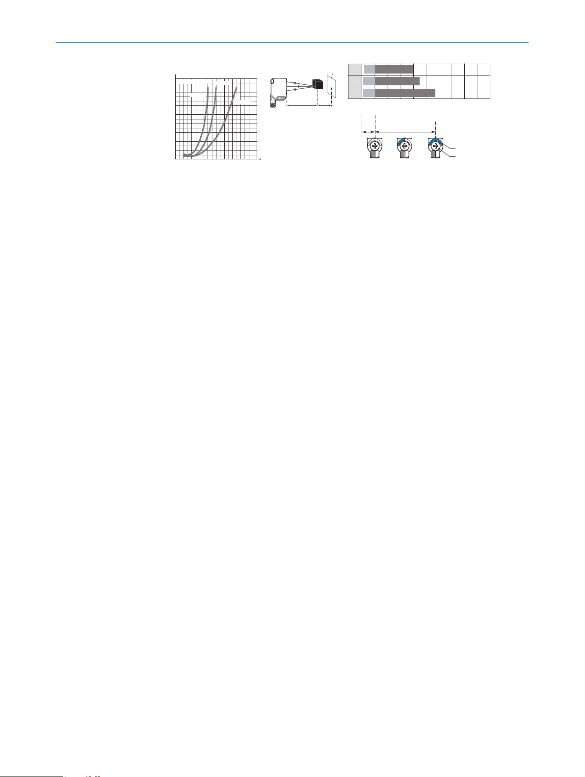
Figure 7: Characteristic line 1, WTS16 Blue‐
100
(3.94)
400
(15.75)
200
(7.87)
A
800
(31.5)
1,000
(39.37)
1,500
(59.06)
0
1
2
3
400
10 500
10
750
BluePilot:
Adjustment range
Distance in mm (inch)
Sensing range indicator
(blue LED)
Teach-Turn adjustment
A = Detection distance (depending on object remission)
100
100
10015
tooth®-xxxxx1xx, red light
Sensing range on black, 6% remission
1
Sensing range on gray, 18% remission
2
Sensing range on white, 90% remission
3
Sensing range setting WTL16, WTS16
COMMISSIONING 6
8022692.10DR | SICK
Subject to change without notice
9
Page 11
1...3 sec.
1
2
3
COMMISSIONING
6
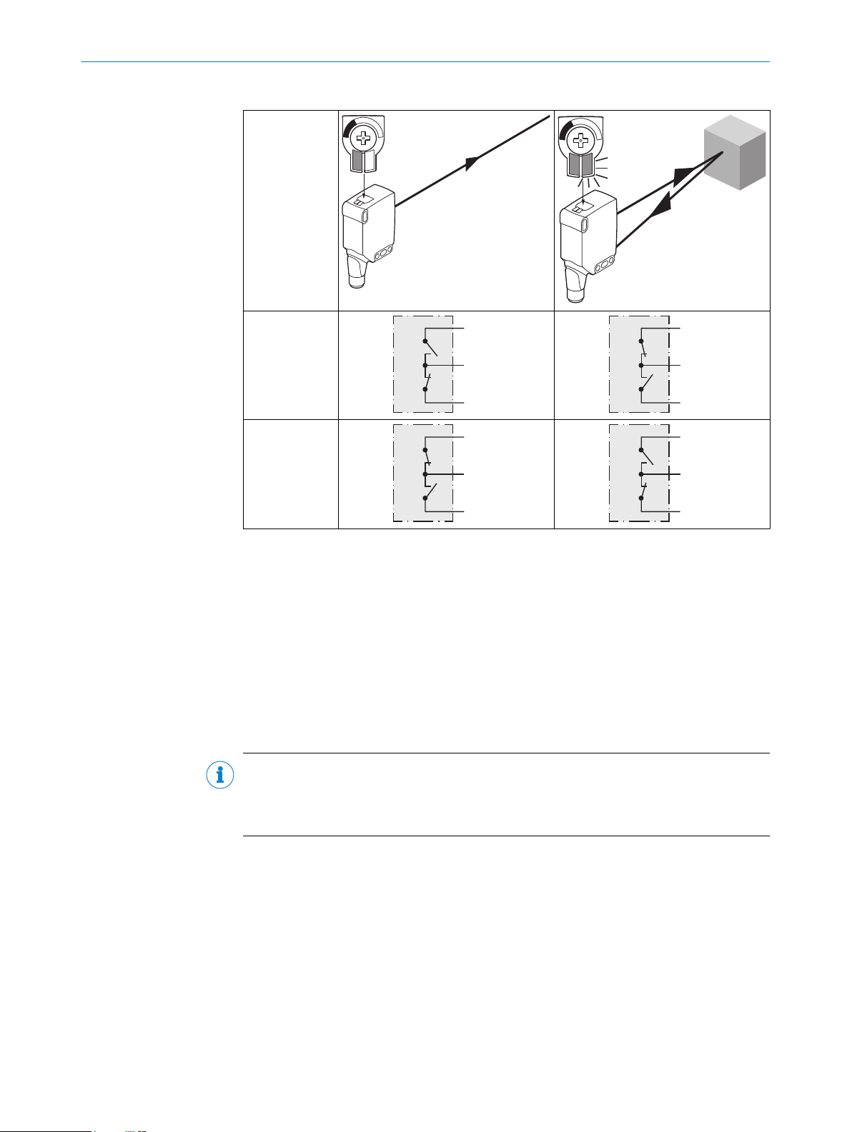
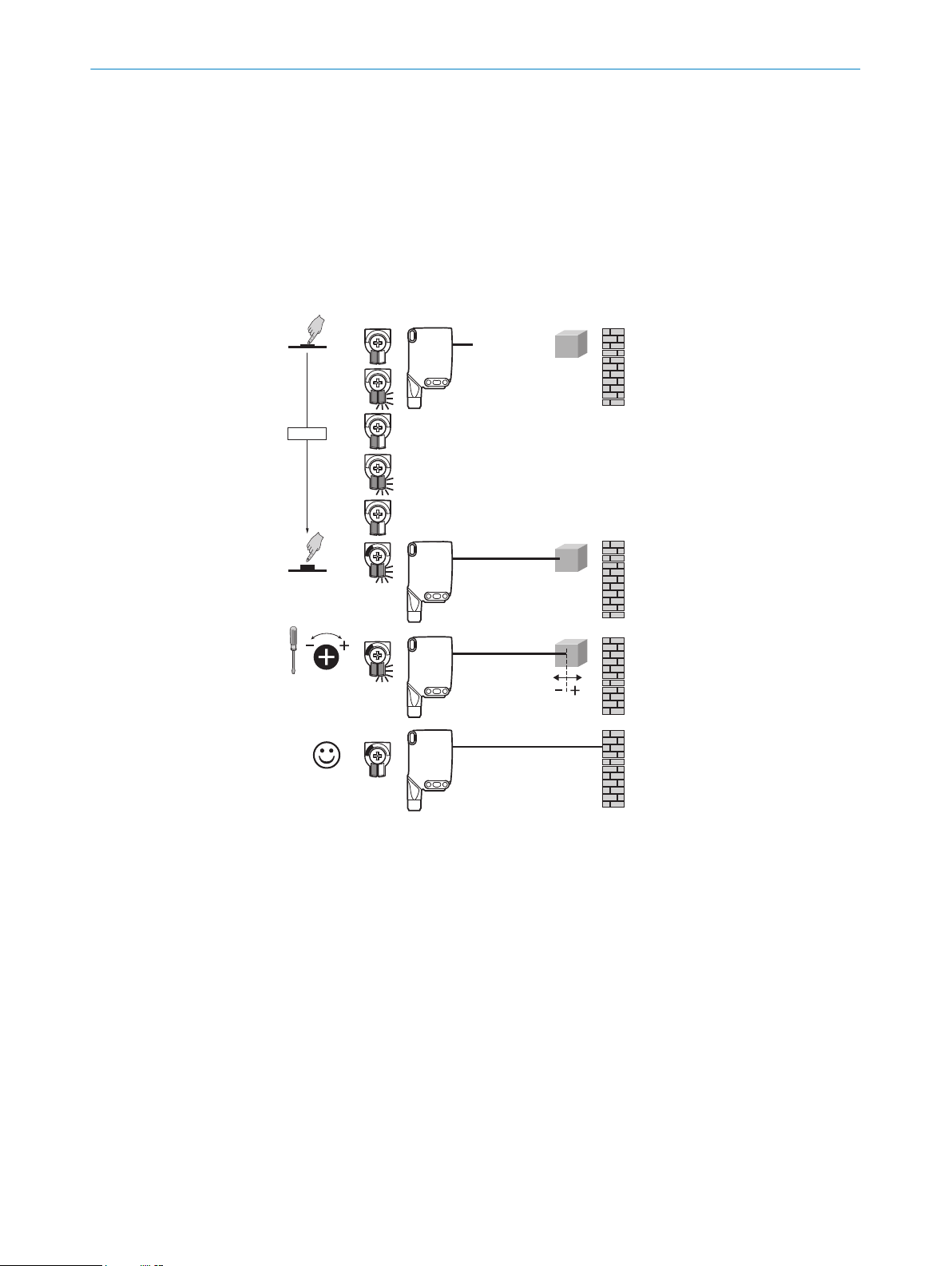
WTL16x-xxxxxx2xAxx, WTS16x-xxxxxx2xAxx with press-turn element:
The sensing range is adjusted by pressing the teach-in button (approx. 1-3 sec.).
Depending on the requirements, the potentiometer can be used for fine-tuning (without
pressing the teach-in button).
Clockwise rotation: sensing range increased.
Counterclockwise rotation: sensing range reduced.
The sensing range can also be adjusted using just the potentiometer. We recommend
placing the object within the sensing range, see figure 8 for an example. Once the sens‐
ing range has been adjusted, the object is removed from the path of the beam, which
causes the background to be suppressed and the switching output to change (see
table 1 and see table 2).
Figure 8: WTL16x-xxxxxx2xAxx, WTS16x-xxxxxx2xAxx red light, adjusting the sensing range with
press-turn element
10
8022692.10DR | SICK
Subject to change without notice
Page 12
1
2
3
COMMISSIONING
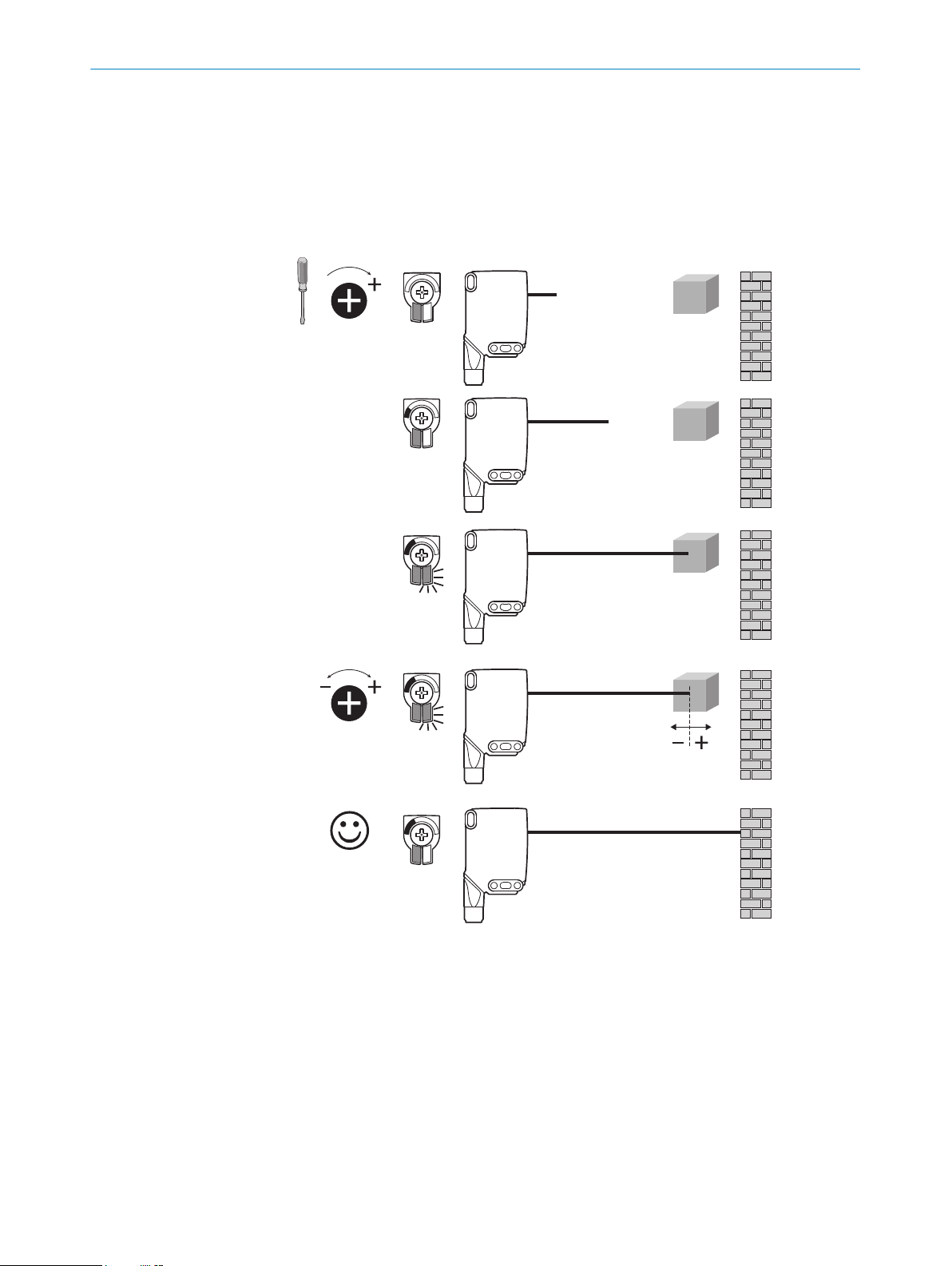
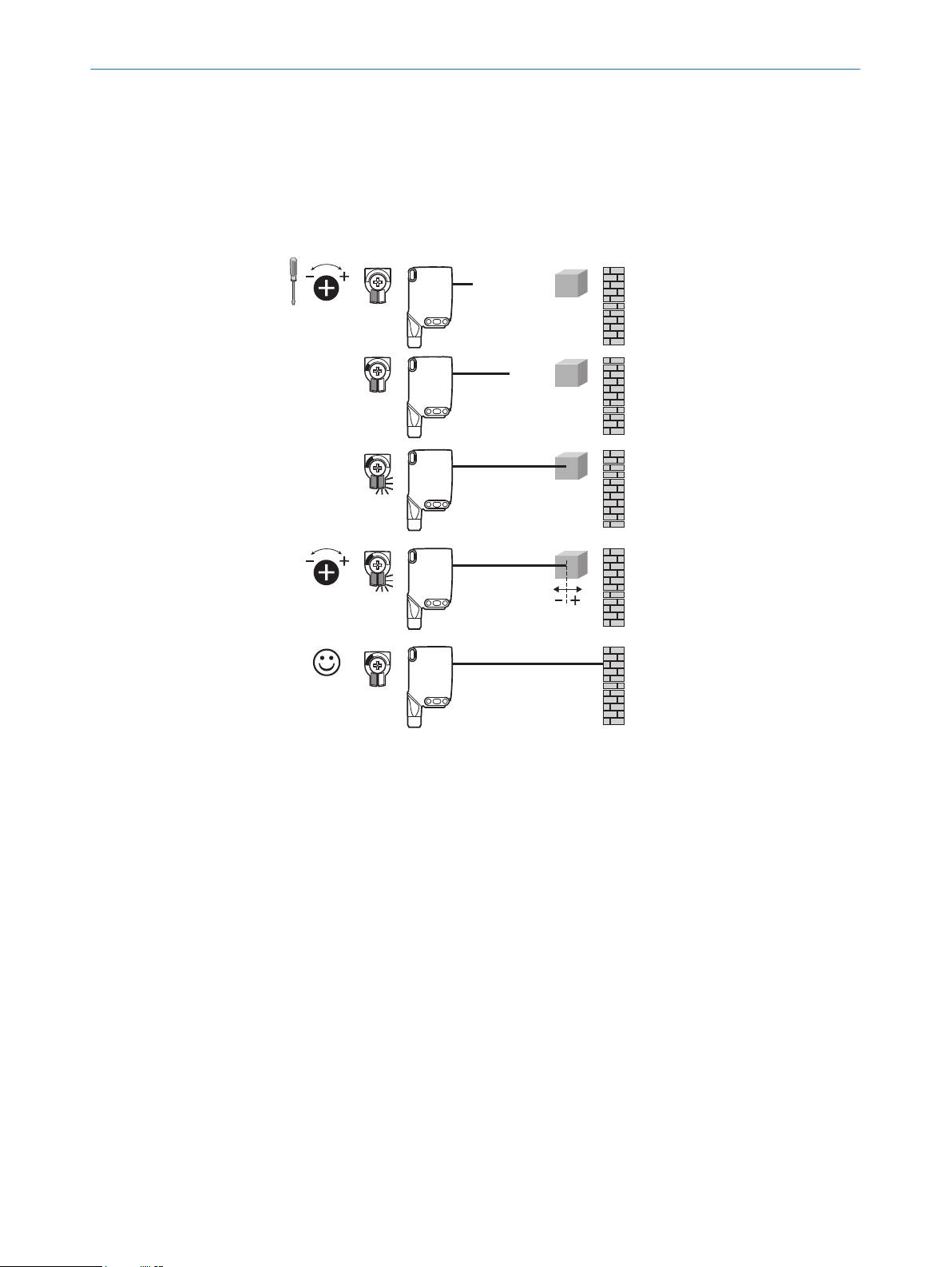
WTL16x-xxxxxx1xAxx, WTS16x-xxxxxx1xAxx with potentiometer:
The sensing range is adjusted with the potentiometer.
Clockwise rotation: sensing range increased.
Counterclockwise rotation: sensing range reduced.
We recommend placing the object within the sensing range, see figure 9 for an exam‐
ple. Once the sensing range has been adjusted, the object is removed from the path of
the beam, which causes the background to be suppressed and the switching output to
change (see table 1 and see table 2).
6
Figure 9: WTL16x-xxxxxx1xAxx, WTS16x-xxxxxx1xAxx red light, adjusting the sensing range with
potentiometer
8022692.10DR | SICK
Subject to change without notice
11
Page 13
1...3 sec.
1
2
COMMISSIONING
6
WTL16x-xxxxxx3xAxx, WTS16x-xxxxxx3xAxx with teach-in button:
The sensing range is adjusted by pressing the teach-in button (approx. 1-3 sec.). We
recommend placing the object within the sensing range, see figure 9 for an example.
Once the sensing range has been adjusted, the object is removed from the path of the
beam, which causes the background to be suppressed and the switching output to
change (see table 1 and see table 2).
Figure 10: WTL16x-xxxxxx3xAxx, WTS16x-xxxxxx3xAx red light, adjusting the sensing range with
teach-in button
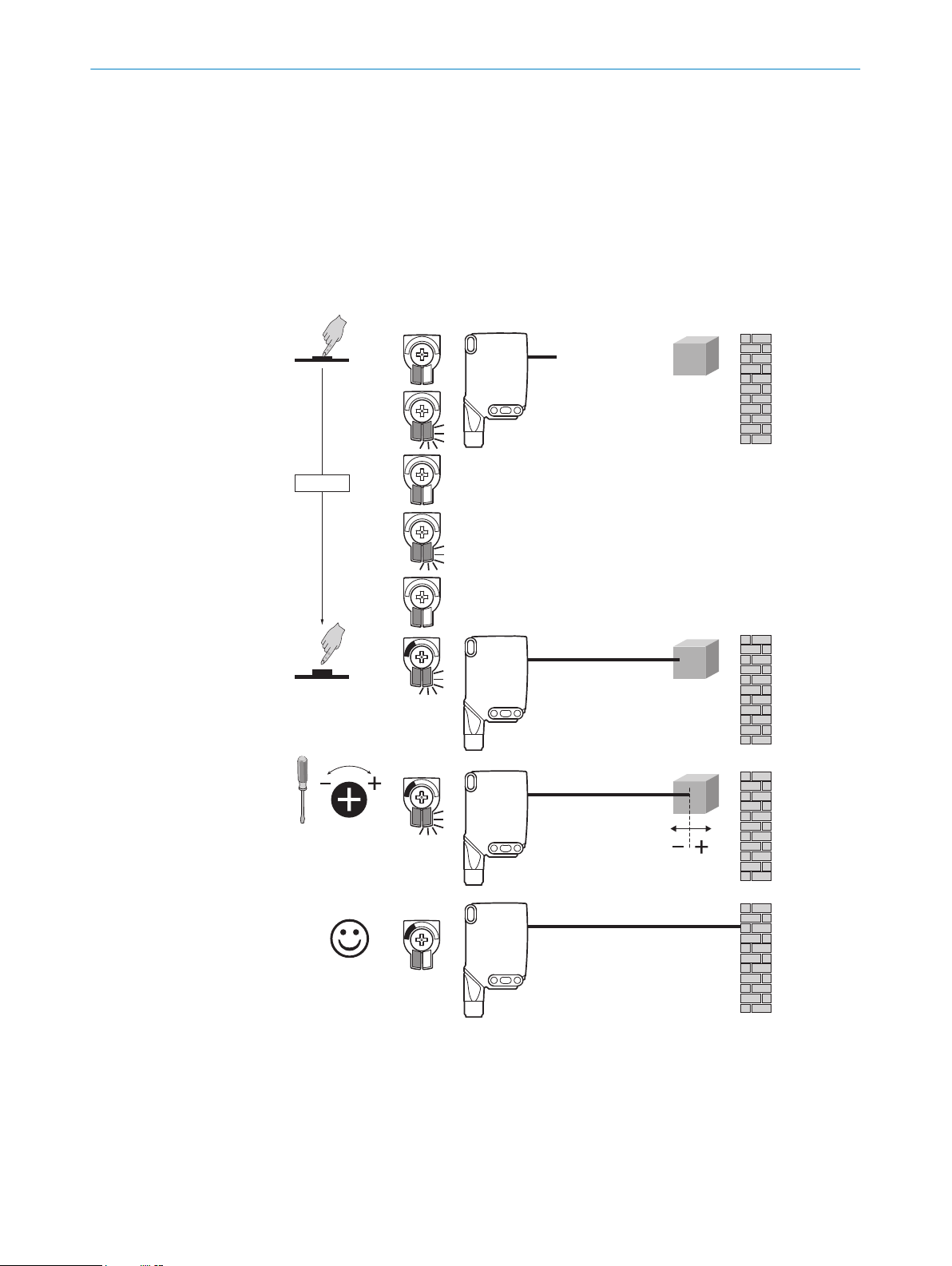
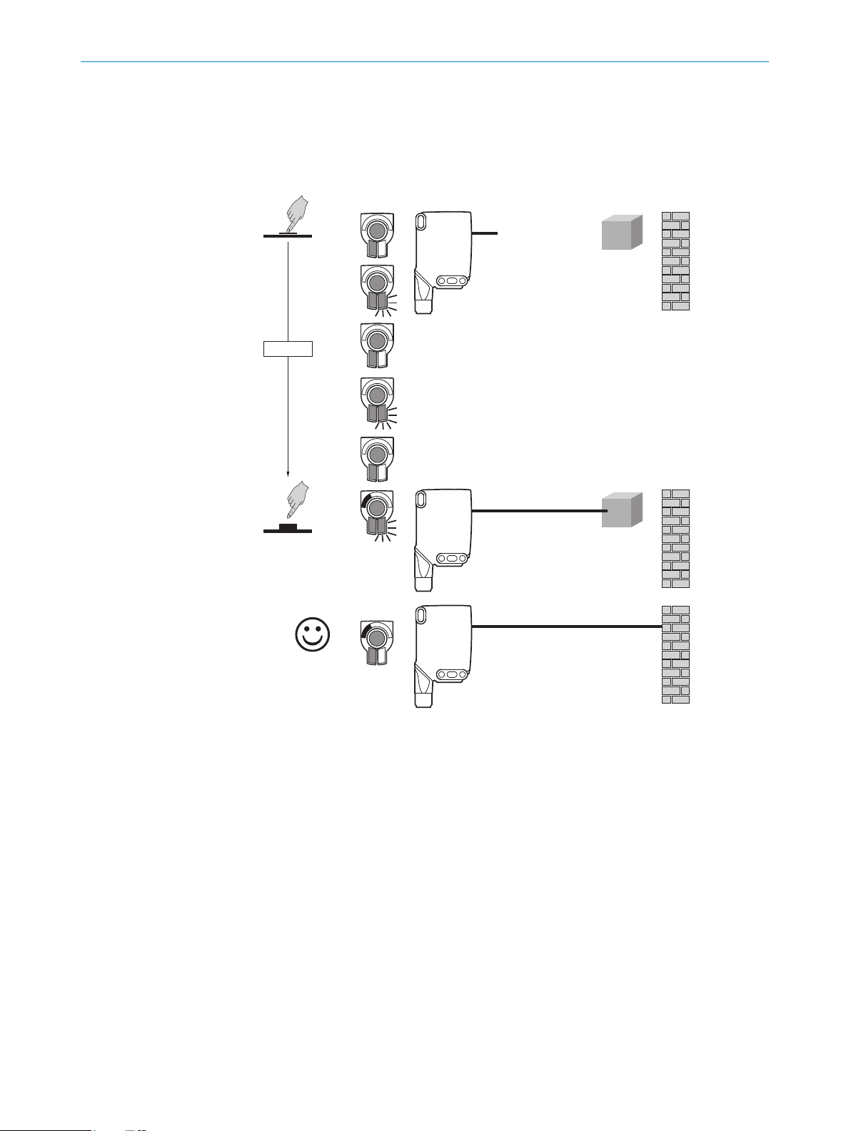
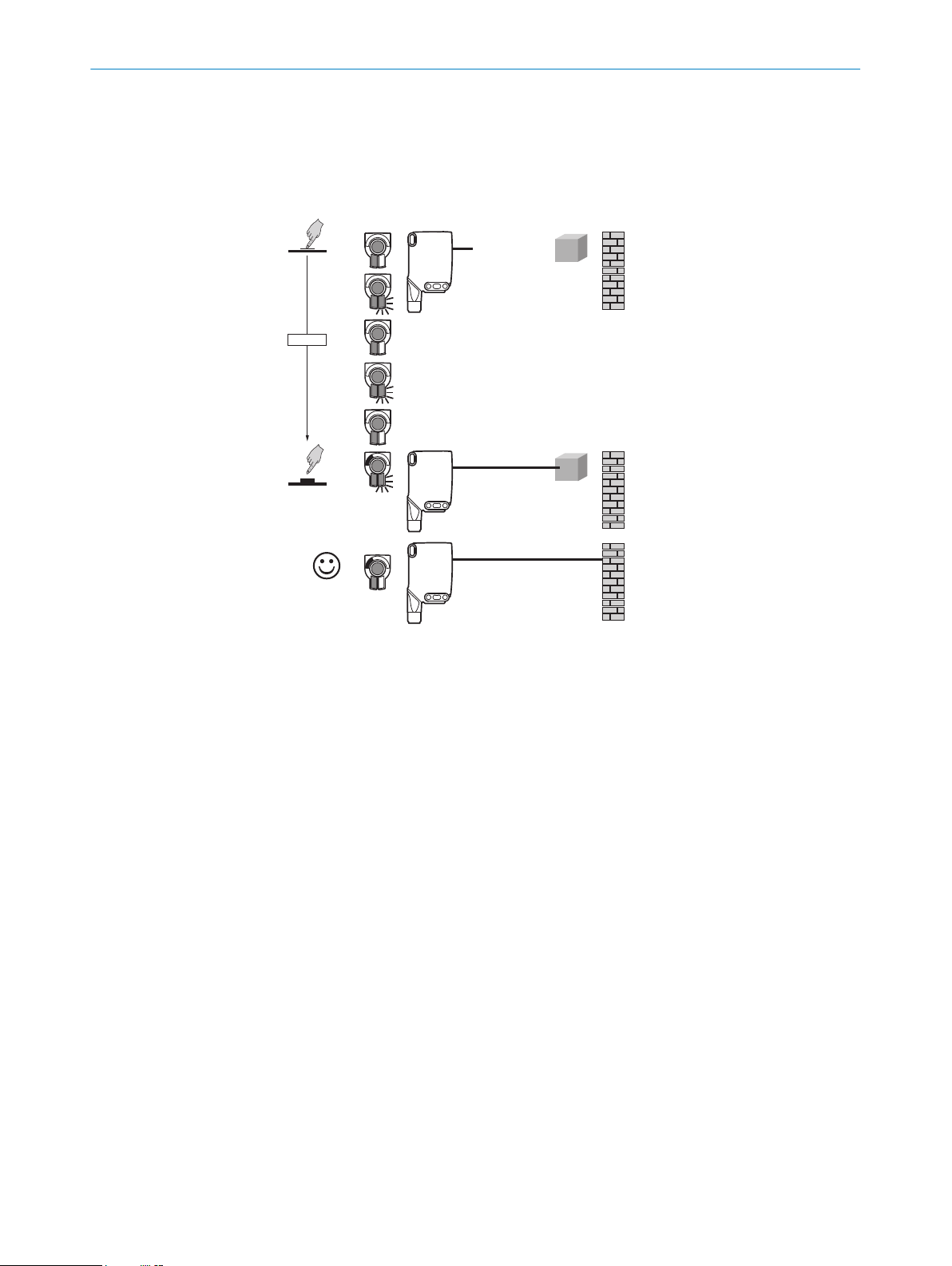
Sensing range setting WTS16
Detection of flat, glossy, contrast-rich, and uneven objects.
If the objects are detected from above, we recommend installing the sensor at an angle
in order to prevent total reflection by a reflective surface
1 When adjusting the sensing range, the light spot should be focused on an even,
uniform surface, e.g. a white sheet of paper.
12
8022692.10DR | SICK
Subject to change without notice
Page 14

1...3 sec.
Figure 11: WTS16 sensing range setting
COMMISSIONING
6
2 Turn the potentiometer a fraction counterclockwise until the yellow LED indicator
no longer lights up. The sensing range is now located a fraction above the con‐
veyor belt.
Figure 12: WTS16 sensing range setting
3 The conveyor belt should now be put into operation without any objects. If the yel‐
low LED indicator does not light up during the test run, the sensing range is set
correctly.
Figure 13: WTS16 sensing range setting
8022692.10DR | SICK
Subject to change without notice
4 If the object is in the path of the beam and the yellow LED indicator lights up, the
sensing range is set correctly.
13
Page 15

7 TROUBLESHOOTING
Figure 14: WTS16 sensing range setting
Process data structure (Version 1.1)
A00 A70 A71 A72 A73 A75
IO-Link V1.1
Process
data
Bit 0 / Data
type
Bit 1 / Data
type
Bit... /
Descrip‐
tion / Data
type
Bit... /
Descrip‐
tion / Data
type
2 ...15 /
[empty]
QL2 / Boolean Qint.1 /
2 ...15 /
[time mea‐
surement
value] /
UInt 14
2 bytes 4 bytes
Byte 0: bits 15... 8
Byte 1: bits 7... 0
QL1 / Boolean
Boolean
2 … 15 /
[counter
value] /
UInt 14
2 … 15 /
[length /
measure‐
ment] /
speed
SInt14
QL2 /
Boolean
2 / Qint.
1 /
Boolean
3 … 15 /
[time mea‐
surement
value] /
UInt13
Byte 0: bits 31...
24
Byte 1: bits 13...
16
Byte 2: bits 15...
8
Byte 3: bits 7... 0
Qint.1 / Boolean
2 … 7 / [empty]
8 … 31 / [carrier
load] / UInt 24
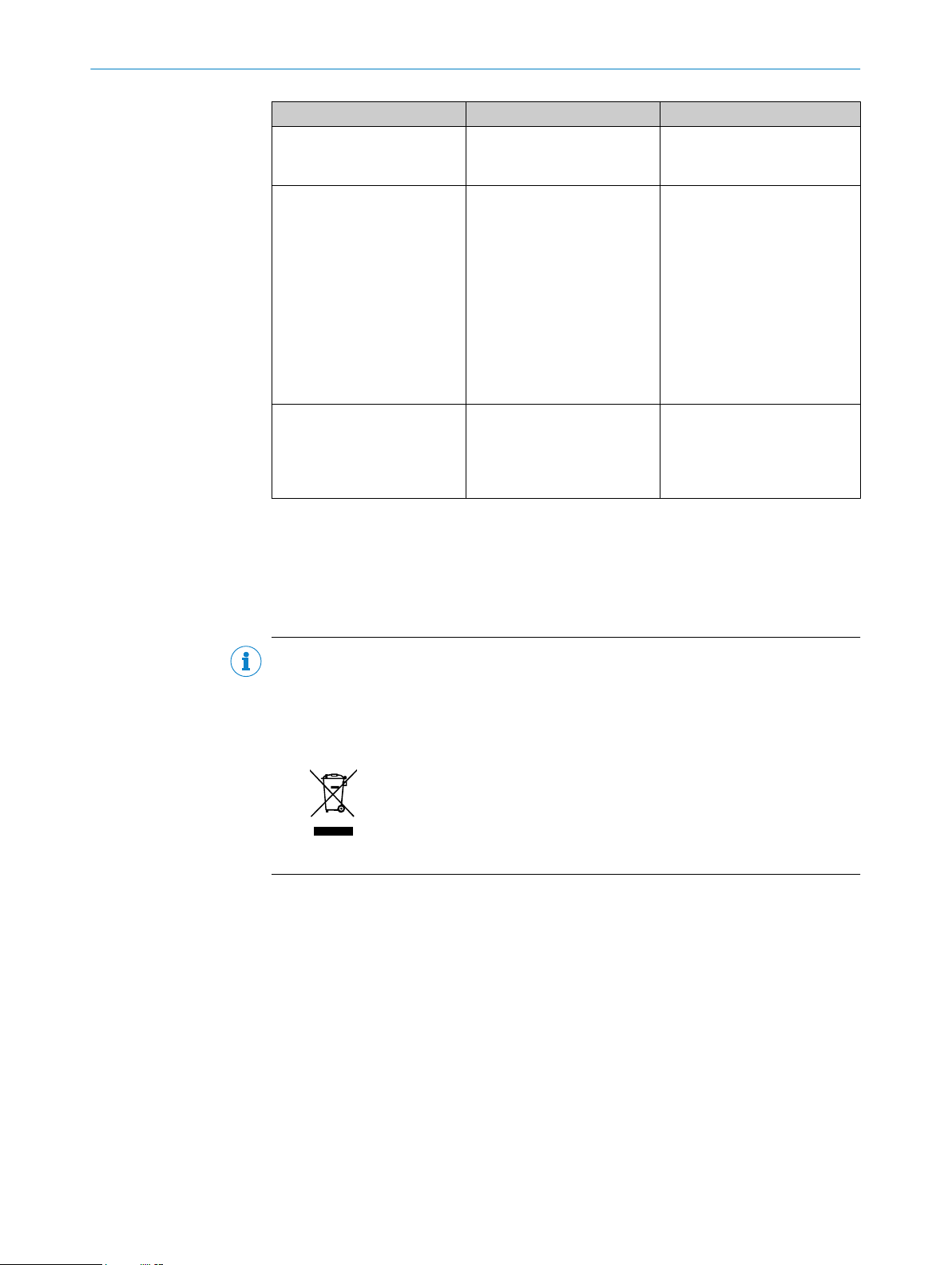
7 Troubleshooting
The Troubleshooting table indicates measures to be taken if the sensor stops working.
LED indicator/fault pattern Cause Measures
Green LED flashes IO-Link communication None
Switching outputs do not
behave in accordance with
table 2
WTS only: yellow LED flashes
quickly
Yellow LED lights up, no object
in the path of the beam
14
1. IO-Link communication
2. Change of the configuration
3. Short-circuit
When adjusting the sensing
range, the light spot is only
half on the object or on a very
high-contrast object
The sensing range distance is
too large
1. None
2. Adjustment of the configura‐
tion
3. Check electrical connections
Sensing range setting accord‐
ing to Section “Sensing range
setting for WTS16”.
Reduce the sensing range
8022692.10DR | SICK
Subject to change without notice
Page 16
DISASSEMBLY AND DISPOSAL 8
LED indicator/fault pattern Cause Measures
Object is in the path of the
beam, yellow LED does not
light up
The sensor is not displayed in
SOPASair
No connection can be made
to the sensor
Distance between the sensor
and the object is too long or
sensing range is set too short
1. Connection to another
hand-held exists.
2.The hand-held is outside of
the transmission range of the
sensor.
3. Bluetooth LE in the sensor
is deactivated.
4. Bluetooth LE in the handheld is deactivated.
5. MAC address filter acti‐
vated, hand-held not autho‐
rized.
1. The Android or iOS version
does not comply with require‐
ments.
2. SOPASair version does not
contain the required driver.
Increase the sensing range
1. No connection or deactiva‐
tion of the existing connection.
2. Thorough check of installa‐
tion situation (e.g. shielding by
metal).
3. Activation of Bluetooth LE
via SiLink2 master or IO-Link
4. Activation of Bluetooth LE
5. No or change to MAC
address filter.
1. Check the operating system.
2. Uninstall SOPASair, install
the most current app version.
8 Disassembly and disposal
The sensor must be disposed of according to the applicable country-specific regula‐
tions. Efforts should be made during the disposal process to recycle the constituent
materials (particularly precious metals).
NOTE
Disposal of batteries, electric and electronic devices
According to international directives, batteries, accumulators and electrical or
•
electronic devices must not be disposed of in general waste.
The owner is obliged by law to return this devices at the end of their life to the
•
respective public collection points.
•
This symbol on the product, its package or in this document, indicates
that a product is subject to these regulations.
9 Maintenance
SICK sensors are maintenance-free.
We recommend doing the following regularly:
8022692.10DR | SICK
Subject to change without notice
Clean the external lens surfaces
•
Check the screw connections and plug-in connections
•
No modifications may be made to devices.
Subject to change without notice. Specified product properties and technical data are
not written guarantees.
15
Page 17

APPROVALS
10
10 Approvals
10.1 Bluetooth® approvals
Country Comments
Canada IC: 21147-W16
USA FCC ID: 2AHDR-W16
Europe + EFTA EU countries
This device complies with Part 15 of the FCC Rules and with Industry Canada licenceexempt RSS standard(s). Operation is subject to the following two conditions: (1) this
device may not cause harmful interference, and (2) this device must accept any inter‐
ference received, including interference that may cause undesired operation.
Belgium (BE), Bulgaria (BG), Denmark (DK), Germany (DE), Estonia
(EE), Finland (FI), France (FR), Greece (GR), Ireland (IE), Italy (IT),
Latvia (LV), Lithuania (LT), Luxembourg (LU), Malta (MT), Nether‐
lands (NL), Austria (AT), Poland (PL), Portugal (PT), Romania (RO),
Sweden (SE), Slovakia (SK), Slovenia (SI), Spain (ES), Czech
Republic (CZ), Hungary (HU), United Kingdom (GB), Republic of
Cyprus (CY).
EFTA countries
Iceland, Liechtenstein, Norway, Switzerland
Le présent appareil est conforme aux CNR d'Industrie Canada applicables aux
appareils radio exempts de licence. L'exploitation est autorisée aux deux conditions
suivantes: (1) l'appareil ne doit pas produire de brouillage, et (2) l'utilisateur de
l'appareil doit accepter tout brouillage radioélectrique subi, même si le brouillage est
susceptible d'en compromettre le fonctionnement.
Changes or modifications made to this equipment not expressly approved by SICK AG
may void the FCC authorization to operate this equipment.
This equipment has been tested and found to comply with the limits for a Class A digital
device, pursuant to Part 15 of the FCC Rules. These limits are designed to provide rea‐
sonable protection against harmful interference when the equipment is operated in a
commercial environment. This equipment generates, uses, and can radiate radio fre‐
quency energy and, if not installed and used in accordance with the instruction manual,
may cause harmful interference to radio communications. Operation of this equipment
in a residential area is likely to cause harmful interference in which case the user will
be required to correct the interference at his own expense.
16
8022692.10DR | SICK
Subject to change without notice
Page 18

TECHNICAL DATA 11
11 Technical data
11.1 Technical data
WTL16 Bluetooth® WTS16 Bluetooth®
Sensing range max. 10 mm ... 500 mm
Light spot diameter/distance 30 mm x 3 mm (200
mm)
Supply voltage V
S
Current consumption ≤ 30 mA
Output current I
max.
Max. response time ≤ 500 µs
Switching frequency 1000 Hz
DC 10 ... 30 V DC 10 ... 30 V
2
< 50 mA
3
≤ 100 mA ≤ 100 mA
4
5
Enclosure rating IP66, IP67 IP66, IP67
Protection class III III
Circuit protection A, B, C, D
6
Ambient operating temperature –40 °C ... +60 °C –40 °C ... +60 °C
1
Object with 90 % remission (based on standard white DIN 5033)
2
16 VDC to 30 VDC, without load
3
10 VDC to 16 VDC, without load
4
Signal transit time with resistive load in switching mode. Deviating values possible in COM2 mode.
5
With a light/dark ratio of 1:1 in switching mode. Deviating values possible in IO-Link mode.
6
A = UV-connections reverse polarity protected
B = inputs and output reverse-polarity protected
C = Interference suppression
D = outputs overcurrent and short-circuit protected
1
10 mm ... 750 mm
Ø 8 mm (300 mm)
≤ 30 mA
< 50 mA
≤ 1,4 ms
350 Hz
A, B, C, D
2
3
4
5
6
1
11.2 Bluetooth technical data®
Features Values
Bluetooth® sensing range 100 m on sight
Radio type BLE
Radio class 2
Bluetooth® module manufacturer BROADCOM
Cypress Semiconductor Corporation
198 Champion Court San Jose
CA 95134-1709
RF band 2,402 - 2,480 MHz
Output power 2 dBM
Declaration ID D033906
Qualified design ID 89630
Specification name 4.1
Member company SICK AG
8022692.10DR | SICK
Subject to change without notice
17
Page 19
WTL16 - WTS16 Bluetooth®
B E T R I E B S A N L E I T U N G
de
en
es
fr
it
ja
pt
ru
zh
Page 20
Beschriebenes Produkt
WTL16, WTS16 - Bluetooth®
Hersteller
SICK AG
Erwin-Sick-Str. 1
79183 Waldkirch
Deutschland
Rechtliche Hinweise
Dieses Werk ist urheberrechtlich geschützt. Die dadurch begründeten Rechte bleiben
bei der Firma SICK AG. Die Vervielfältigung des Werks oder von Teilen dieses Werks ist
nur in den Grenzen der gesetzlichen Bestimmungen des Urheberrechtsgesetzes zuläs‐
sig. Jede Änderung, Kürzung oder Übersetzung des Werks ohne ausdrückliche schriftli‐
che Zustimmung der Firma SICK AG ist untersagt.
Die in diesem Dokument genannten Marken sind Eigentum ihrer jeweiligen Inhaber.
© SICK AG. Alle Rechte vorbehalten.
Originaldokument
Dieses Dokument ist ein Originaldokument der SICK AG.
8022692.10DR | SICK
Subject to change without notice
19
Page 21

INHALT
Inhalt
12 Zu Ihrer Sicherheit............................................................................. 21
12.1 Allgemeine Sicherheitshinweise.............................................................. 21
12.2 Hinweise zur UL Zulassung...................................................................... 21
13 Bestimmungsgemäße Verwendung............................................... 21
14 Bedien- und Anzeigeelemente........................................................ 21
15 Montage.............................................................................................. 23
16 Elektrische Installation..................................................................... 23
17 Inbetriebnahme................................................................................. 24
18 Störungsbehebung............................................................................ 31
19 Demontage und Entsorgung............................................................ 32
20 Wartung.............................................................................................. 32
21 Zulassungen....................................................................................... 33
21.1 Bluetooth® Zulassungen......................................................................... 33
22 Technische Daten.............................................................................. 34
22.1 Technische Daten..................................................................................... 34
22.2 Technische Daten Bluetooth®................................................................. 34
20
8022692.10DR | SICK
Subject to change without notice
Page 22
12 Zu Ihrer Sicherheit
2006/42/EC
NO
SAFETY
12.1 Allgemeine Sicherheitshinweise
■
Lesen Sie vor der Inbetriebnahme des Geräts die Betriebsanleitung.
■
Der Anschluss, die Montage und die Konfiguration des Geräts dürfen nur
von geschultem Fachpersonal vorgenommen werden.
■
Bei diesem Gerät handelt es sich um kein sicherheitsgerichtetes Bauteil im
Sinne der EU-Maschinenrichtlinie.
■
Bei der Inbetriebnahme ist das Gerät ausreichend vor Feuchtigkeit und Ver‐
schmutzung zu schützen.
■
Die vorliegende Betriebsanleitung enthält Informationen, die während des Lebens‐
zyklus der Lichtschranke benötigt werden.
ZU IHRER SICHERHEIT 12
12.2 Hinweise zur UL Zulassung
The device must be supplied by a Class 2 source of supply.
UL Environmental Rating: Enclosure type 1
13 Bestimmungsgemäße Verwendung
Die WTL16 Bluetooth® , WTS16 Bluetooth® ist ein optoelektronischer Reflexions-Licht‐
taster (im Folgenden Sensor genannt) und wird zum optischen, berührungslosen Erfas‐
sen von Sachen, Tieren und Personen eingesetzt. Bei jeder anderen Verwendung und
bei Veränderungen am Produkt verfällt jeglicher Gewährleistungsanspruch gegenüber
der SICK AG.
Die WTS16 ist besonders zur Detektion von flachen, glänzenden, kontrastreichen und
unebenen Objekten geeignet.
14 Bedien- und Anzeigeelemente
Reflexionslichttaster mit Hintergrundausblendung.
8022692.10DR | SICK
Subject to change without notice
21
Page 23
20
Ø 12,9
Ø 4,1
39,9
55,4
45,5
5
42
29,9
6
3
6,5
15
27,8
7,7
7,8
7,2
35,5
4,1
16
8,3
55,7
5
4
89
16
18,5
3
2
1
6
7
20
M12
18
Ø 4,1
39,9
55,4
55,7
45,5
5
7
42
29,9
52,9
6
17,5
3
6,5
15
28
7,5
35,5
4,1
5
4
16
16 18,5
3
2
1
89
6
7
Ø 4,1
39,9
55,4
45,5
5
42
29,9
6
3
6,5
15
27,8
7,7
7,8
7,2
35,5
4,1
16
55,7
4
3
12,2
12,2
1
2
2
20
24,2
Ø 12,9
8,3
78
5
6
M12
12,2
12,2
4
3
1
2
2
17,5
Ø 4,1
7
39,9
55,4
55,7
45,5
5
29,9
52,9
6)
3
6,5
15
28
7,5
35,5
4,1
42
20
18
24,2
16
78
5
6
14 BEDIEN- UND ANZEIGEELEMENTE
Abbildung 15: Maßzeichnung 1, WTL16 Lei‐
tung
Vorzugsrichtung des Tastgutes
1
Mitte Optikachse Sender
2
Mitte Optikachse Empfänger
3
Befestigungsbohrung, Ø 4,1 mm
4
Anschluss
5
Anzeige-LED grün: Betriebsspan‐
6
nung aktiv
Anzeige-LED gelb: Status Lichtemp‐
7
fang
Drück-Dreh-Element: Einstellung
8
des Schaltabstands
BluePilot blau: Schaltabstandsan‐
9
zeige
Abbildung 16: Maßzeichnung 2, WTL16
Stecker
Abbildung 17: Maßzeichnung 3, WTS16
Abbildung 18: Maßzeichnung 1, WTS16
Stecker
8022692.10DR | SICK
Subject to change without notice
Leitung
Mitte Optikachse Sender
1
Mitte Optikachse Empfänger
2
Befestigungsbohrung, Ø 4,1 mm
3
Anschluss
4
Anzeige-LED grün: Betriebsspan‐
5
nung aktiv
Anzeige-LED gelb: Status Lichtemp‐
6
fang
22
Page 24

Drück-Dreh-Element: Einstellung
1
2
4 3
1
2
4 3
1
2
4 3
7
des Schaltabstands
BluePilot blau: Schaltabstandsan‐
8
zeige
15 Montage
Den Sensor an einen geeigneten Befestigungswinkel montieren (siehe SICK-ZubehörProgramm).
Maximal zulässiges Anzugsdrehmoment des Sensors von < 1,3 Nm beachten.
Vorzugsrichtung des Objektes zum Sensor beachten, siehe Abbildung 15, Abbildung 16
(gilt nur für WTL16).
16 Elektrische Installation
Anschluss der Sensoren muss spannungsfrei (UV = 0 V) erfolgen. Je nach Anschlussart
sind die folgenden Informationen zu beachten:
– Steckeranschluss: Pinbelegung beachten.
– Leitung: Adernfarbe
MONTAGE 15
Erst nach Anschluss aller elektrischen Verbindungen die Spannungsversorgung (UV > 0
V) anlegen bzw. einschalten.
Erläuterungen zum Anschlussschema (Tabelle 3, Tabelle 4).
MF (Pin-2-Konfiguration) = Externer Eingang, Teach-in, Schaltsignal
QL1/C = Schaltausgang, IO-Link Kommunikation
DC: 10 ... 30 V DC
Tabelle 3: DC
WTL16
WTS16
1 + (L+)
2 MF
3 - (M)
4 QL1/C
Default: MF
Default:
QL1/C
-24161xxxA00
-34161xxxA00
Q Q
Q Q
-1x161xxxA00-24162xxxA0
0
-34162xxxA0
0
Q Q www.sick.com
Q Q
1 = brn
2 = wht
3 = blu
4 = blk
-1x162xxxA00-2416xxxxA01A99
-3416xxxxA01A99
8022709
www.sick.com
8022709
1 = brn
2 = wht
3 = blu
4 = blk
8022692.10DR | SICK
Subject to change without notice
0.14 mm
AWG26
2
0.14 mm
2
AWG26
23
Page 25
+ (L+)
Q
‒ (M)
+ (L+)
Q
‒ (M)
+ (L+)
Q
‒ (M)
+ (L+)
Q
‒ (M)
17 INBETRIEBNAHME
Tabelle 4: Push / Pull
Q
push-pull
(≤ 100 mA)
Q
push-pull
(≤ 100 mA)
17 Inbetriebnahme
Bluetooth® ist bei der Ersteinbetriebnahme eingeschaltet. SOPASair erhalten Sie im
Google PlayStore (Android) und im App Store (iOS).
Anforderungen an das Betriebssystem: Android-Version 6.0, iOS aktuellste Version.
Ausrichtung
WTL16 Bluetooth®, WTS16 Bluetooth®: Sensor auf Objekt ausrichten. Positionierung
so wählen, dass der rote Sendelichtstrahl in der Mitte des Objekts auftrifft. Es ist dar‐
auf zu achten, dass die optische Öffnung (Frontscheibe) des Sensors vollständig frei ist
[Abbildung 19].
HINWEIS
Bei WTS16: Wenn die Detektion der Objekte von oben erfolgt, empfehlen wir einen
geneigten Einbau des Sensors, damit eine Totalreflexion durch eine spiegelnde Oberflä‐
che vermieden wird, siehe Abbildung 25 - Abbildung 28.
24
8022692.10DR | SICK
Subject to change without notice
Page 26
WTL16 WTS16
0
10
5
35
30
25
20
15
45
40
50
100 200 300 600400 500
0
Abstand in mm
1
2
3
WTL16P-xxxxx1xx
18%/90%
6%/90%
90%/90%
Mindestabstand in mm (y) zwischen eingestelltem
Schaltabstand und Hintergrund (weiß, 90%)
y
x
yx
weißer Hintergrund (90%)
Beispiel:
Schaltabstand auf Schwarz, 6%,
x = 200 mm, y = 15 mm
100 200
Einstellbereich
Abstand in mm
A
300 400 500
0
1
2
3
50 300
25 400
10
500
BluePilot:
Schaltabstandsanzeige (blaue LED)
Drück-Dreh-Element
A = Detektionsabstand (abhängig von Objektremission)
100
100
100
INBETRIEBNAHME 17
Abbildung 19: Ausrichtung
Schaltabstand
Einsatzbedingungen prüfen: Schaltabstand und Distanz zum Objekt bzw. Hintergrund
sowie Remissionsvermögen des Objektes mit dem zugehörigen Diagramm [siehe
Abbildung 20, Abbildung 21] abgleichen (x = Schaltabstand, y = Mindestabstand zwi‐
schen eingestelltem Schaltabstand und Hintergrund (weiß 90%)). Remission: 6 % =
schwarz 1, 18 % = grau 2, 90 % = weiß 3 (bezogen auf Standardweiß nach DIN
5033). Wir empfehlen, die Einstellung mit einem Objekt von niedriger Remission vorzu‐
nehmen.
Die minimale Distanz (= y) für die Hintergrundausblendung kann aus dem Diagramm
[Abbildung 20 1] wie folgt ermittelt werden:
Beispiel: x = 200 mm, y = 15 mm. D. h. der Hintergrund (weiß, 90%) wird ab einer Dis‐
tanz von > 15 mm vom Sensor ausgeblendet.
Abbildung 20: Kennlinie 1, WTL16 Bluetooth®-
Schaltabstand auf Schwarz, 6 % Remis‐
1
sion
Schaltabstand auf Grau, 18 % Remission
2
Schaltabstand auf Weiß, 90 % Remis‐
3
sion
8022692.10DR | SICK
Subject to change without notice
xxxxx1xx, Rotlicht
25
Page 27

0
20
10
60
50
40
30
80
70
90
200 400 600 1.000800
0
Abstand in mm
1
2
3
WTS16P-xxxxx1xx
18%/90%
6%/90%
90%/90%
Mindestabstand in mm (y) zwischen eingestelltem
Schaltabstand und Hintergrund (weiß, 90%)
y
x
yx
weißer Hintergrund (90%)
Beispiel:
Schaltabstand auf Schwarz, 6%,
x = 300 mm, y = 20 mm
100 400200
Einstellbereich
Abstand in mm
A
800 1.000 1.500
0
1
2
3
15 400
10 500
10
750
BluePilot:
Schaltabstandsanzeige (blaue LED)
Drück-Dreh-Element
A = Detektionsabstand (abhängig von Objektremission)
100
100
100
17 INBETRIEBNAHME
Abbildung 21: Kennlinie 1, : WTS16 Bluetooth®-
xxxxx1xx, Rotlicht
Schaltabstand auf Schwarz, 6 % Remis‐
1
sion
Schaltabstand auf Grau, 18 % Remission
2
Schaltabstand auf Weiß, 90 % Remis‐
3
sion
Einstellung Schaltabstand WTL16, WTS16
26
8022692.10DR | SICK
Subject to change without notice
Page 28
1...3 sec.
1
2
3
INBETRIEBNAHME
17
WTL16x-xxxxxx2xAxx, WTS16x-xxxxxx2xAxx mit Drück-Dreh-Element:
Durch Drücken der Teach-in-Taste (ca. 1- 3 sec.) wird der Schaltabstand eingestellt. Je
nach Anforderungen kann mit dem Potentiometer (ohne Drücken der Teach-in-Taste)
eine Feineinstellung vorgenommen werden.
Drehung nach rechts: Erhöhung des Schaltabstandes.
Drehung nach links: Verringerung des Schaltabstandes.
Der Schaltabstand kann auch alleinig mit dem Potentiometer eingestellt werden. Wir
empfehlen, den Schaltabstand in das Objekt zu legen, z.B. siehe Abbildung 8. Nachdem
der Schaltabstand eingestellt worden ist, das Objekt aus dem Strahlengang entfernen,
der Hintergrund wird dabei ausgeblendet und der Schaltausgang ändert sich (siehe
Tabelle 3, Tabelle 4).
8022692.10DR | SICK
Subject to change without notice
Abbildung 22: WTL16x-xxxxxx2xAxx, WTS16x-xxxxxx2xAxx Rotlicht, Einstellung des Schaltabstan‐
des mit Drück-Dreh-Element
27
Page 29
1
2
3
INBETRIEBNAHME
17
WTL16x-xxxxxx1xAxx, WTS16x-xxxxxx1xAxx mit Potentiometer:
Mit dem Potentiometer wird der Schaltabstand eingestellt.
Drehung nach rechts: Erhöhung des Schaltabstandes.
Drehung nach links: Verringerung des Schaltabstandes.
Wir empfehlen, den Schaltabstand in das Objekt zu legen, z.B. siehe Abbildung 9. Nach‐
dem der Schaltabstand eingestellt worden ist, das Objekt aus dem Strahlengang entfer‐
nen, der Hintergrund wird dabei ausgeblendet und der Schaltausgang ändert sich
(siehe Tabelle 3, Tabelle 4).
Abbildung 23: WTL16x-xxxxxx1xAxx, WTS16x-xxxxxx1xAxx Rotlicht, Einstellung des Schaltabstan‐
des mit Potentiometer
28
8022692.10DR | SICK
Subject to change without notice
Page 30
1...3 sec.
1
2
INBETRIEBNAHME
17
WTL16x-xxxxxx3xAxx, WTS16x-xxxxxx3xAxx mit Teach-in-Taste:
Durch Drücken der Teach-in-Taste (ca. 1- 3 sec.) wird der Schaltabstand eingestellt. Wir
empfehlen, den Schaltabstand in das Objekt zu legen, z.B. siehe Abbildung 9. Nachdem
der Schaltabstand eingestellt worden ist, das Objekt aus dem Strahlengang entfernen,
der Hintergrund wird dabei ausgeblendet und der Schaltausgang ändert sich (siehe
Tabelle 3, Tabelle 4).
Abbildung 24: WTL16x-xxxxxx3xAxx, WTS16x-xxxxxx3xAx Rotlicht, Einstellung des Schaltabstan‐
des mit Teach-in-Taste
Einstellung Schaltabstand WTS16
Detektion von flachen, glänzenden, kontrastreichen und unebenen Objekten.
Wenn die Detektion der Objekte von oben erfolgt, empfehlen wir einen geneigten Ein‐
bau des Sensors, damit eine Totalreflexion durch eine spiegelnde Oberfläche vermie‐
den wird
1 Für die Einstellung des Schaltabstandes soll der Lichtfleck auf eine homogene und
ebene Oberfläche, z.B. weißes Blatt, ausgerichtet werden.
8022692.10DR | SICK
Subject to change without notice
29
Page 31

1...3 sec.
INBETRIEBNAHME
17
Abbildung 25: Einstellung Schaltabstand WTS16
2 Das Potentiometer nur minimal nach links drehen bis die gelbe Anzeige-LED nicht
mehr leuchtet. Der Schaltabstand befindet sich nun minimal oberhalb des Förder‐
bandes.
Abbildung 26: Einstellung Schaltabstand WTS16
3 Das Förderband soll nun ohne Objekte in Betrieb genommen werden. Wenn die
gelbe Anzeige-LED während des Testlaufs nicht leuchtet, ist der Schaltabstand kor‐
rekt eingestellt.
Abbildung 27: Einstellung Schaltabstand WTS16
30
4 Wenn das Objekt im Strahlengang ist und die gelbe Anzeige-LED leuchtet, ist der
Schaltabstand korrekt eingestellt.
8022692.10DR | SICK
Subject to change without notice
Page 32

Abbildung 28: Einstellung Schaltabstand WTS16
Process data structure (Version 1.1)
A00 A70 A71 A72 A73 A75
IO-Link V1.1
Process
data
Bit 0/ Data
type
Bit 1/ Data
type
Bit... /
Descrip‐
tion / Data
type
Bit... /
Descrip‐
tion / Data
type
2...15 /
[empty]
QL2 / Boolean Qint.1 /
2...15 /
[Time
measure‐
ment
value] /
UInt 14
2 Byte 4 Byte
Byte 0 : Bit 15... 8
Byte 1: Bit 7... 0
QL1 / Boolean
Boolean
2 … 15 /
[Counter
value] /
UInt 14
2 … 15 /
[Length /
measure‐
ment] /
STÖRUNGSBEHEBUNG 18
Byte 0 : Bit 31...
Byte 1: Bit 13... 16
Byte 2: Bit 15... 8
Byte 3: Bit 7... 0
speed
SInt14
QL2 / Boo‐
lean
2 / Qint.
1 / Boo‐
lean
3 … 15 /
[Time
measure‐
ment
value] /
UInt13
Qint.1 / Boolean
2…7 / [empty]
8 … 31 / [Carrier
load] / UInt 24
24
18 Störungsbehebung
Tabelle Störungsbehebung zeigt, welche Maßnahmen durchzuführen sind, wenn die
Funktion des Sensors nicht mehr gegeben ist.
Anzeige-LED / Fehlerbild Ursache Maßnahme
grüne LED blinkt IO-Link Kommunikation keine
Schaltausgänge verhalten sich
nicht gemäß
Tabelle 4
Nur WTS: gelbe LED blinkt
schnell
8022692.10DR | SICK
Subject to change without notice
1. IO-Link Kommunikation
2. Änderung der Konfiguration
3. Kurzschluss
Während der Einstellung des
Schaltabstandes befindet sich
der Lichtfleck nur zur Hälfte
auf dem Objekt oder auf
einem sehr kontrastreichen
Objekt
1. keine
2. Anpassung der Konfigura‐
tion
3. Elektrische Anschlüsse prü‐
fen
Einstellung des Schaltabstan‐
des gemäß Abschnitt "Einstel‐
lung Schaltabstand für
WTS16".
31
Page 33

19 DEMONTAGE UND ENTSORGUNG
Anzeige-LED / Fehlerbild Ursache Maßnahme
gelbe LED leuchtet, kein
Objekt im Strahlengang
Objekt ist im Strahlengang,
gelbe LED leuchtet nicht
In SOPASair wird der Sensor
nicht angezeigt
Es kann keine Verbindung
zum Sensor aufgebaut werden
Schaltabstand ist auf zu gro‐
ßen Abstand eingestellt
Abstand zwischen Sensor und
Objekt ist zu groß oder Schalt‐
abstand ist zu gering einge‐
stellt
1. Verbindung zu einem ande‐
ren Handheld besteht.
2.Das Handheld befindet sich
außerhalb des Sendebereichs
des Sensors.
3. Bluetooth LE im Sensor ist
deaktiviert.
4. Bluetooth LE im Handheld
ist deaktiviert.
5. MAC-Adressfilter aktiviert,
Handheld nicht autorisiert.
1. Die Android bzw. iOS-Ver‐
sion entspricht nicht den
Anforderungen.
2. SOPASair Version enthält
nicht den erforderlichen Trei‐
ber.
Schaltabstand verringern
Schaltabstand vergrößern
1. keine bzw. Deaktivierung der
bestehenden Verbindung.
2. Prüfung der Einbausituation
(z.B. Abschirmung durch
Metall).
3. Aktivierung von Bluetooth LE
per SiLink2 Master oder IOLink
4. Aktivierung von Bluetooth LE
5. keine bzw. Änderung des
MAC-Adress-Filters.
1. Prüfen Sie das Betriebssys‐
tem.
2. Deinstallieren Sie SOPASair,
Installieren Sie die aktuellste
App-Version.
19 Demontage und Entsorgung
Die Lichtschranke muss entsprechend den geltenden länderspezifischen Vorschriften
entsorgt werden. Bei der Entsorgung sollte eine werkstoffliche Verwertung (insbeson‐
dere der Edelmetalle) angestrebt werden.
HINWEIS
Entsorgung von Batterien, Elektro- und Elektronikgeräten
Gemäß den internationalen Vorschriften dürfen Batterien, Akkus sowie Elektro-
•
und Elektronikgeräte nicht mit dem Hausmüll entsorgt werden.
Der Besitzer ist gesetzlich verpflichtet, diese Geräte am Ende ihrer Lebensdauer
•
bei den entsprechenden öffentlichen Sammelstellen abzugeben.
•
Dieses Symbol auf dem Produkt, dessen Verpackung oder im vorliegen‐
den Dokument gibt an, dass ein Produkt den genannten Vorschriften unterliegt.
20 Wartung
SICK-Sensoren sind wartungsfrei.
Wir empfehlen, in regelmäßigen Abständen
32
die optischen Grenzflächen zu reinigen
•
Verschraubungen und Steckverbindungen zu überprüfen
•
Veränderungen an Geräten dürfen nicht vorgenommen werden.
Irrtümer und Änderungen vorbehalten. Angegebene Produkteigenschaften und techni‐
sche Daten stellen keine Garantieerklärung dar.
8022692.10DR | SICK
Subject to change without notice
Page 34

21 Zulassungen
21.1 Bluetooth® Zulassungen
Land Kommentare
Canada IC: 21147-W16
USA FCC ID: 2AHDR-W16
Europa + EFTA EU Länder
This device complies with Part 15 of the FCC Rules and with Industry Canada licenceexempt RSS standard(s). Operation is subject to the following two conditions: (1) this
device may not cause harmful interference, and (2) this device must accept any interfe‐
rence received, including interference that may cause undesired operation.
ZULASSUNGEN
Belgium (BE), Bulgaria (BG), Denm ark (DK), Germany (DE), Esto‐
nia (EE), Finland (FI), France (FR), Greece (GR), Ireland (IE), Italy
(IT), Latvia (LV), Lithuania (LT), Luxembourg (LU), Malta (MT),
Netherlands (NL), Austria (AT), Poland (PL), Portugal (PT), Romania
(RO), Sweden (SE), Slovakia (SK), Slovenia (SI), Spain (ES), Czech
Republic (CZ), Hungary (HU), Unit ed Kingdom (GB), Republic of
Cyprus (CY).
EFTA Länder
Iceland, Liechtenstein, Norway, Switzerland
21
Le présent appareil est conforme aux CNR d'Industrie Canada applicables aux appa‐
reils radio exempts de licence. L'exploitation est autorisée aux deux conditions suivan‐
tes: (1) l'appareil ne doit pas produire de brouillage, et (2) l'utilisateur de l'appareil doit
accepter tout brouillage radioélectrique subi, même si le brouillage est susceptible d'en
compromettre le fonctionnement.
Changes or modifications made to this equipment not expressly approved by SICK AG
may void the FCC authorization to operate this equipment.
This equipment has been tested and found to comply with the limits for a Class A digital
device, pursuant to Part 15 of the FCC Rules. These limits are designed to provide rea‐
sonable protection against harmful interference when the equipment is operated in a
commercial environment. This equipment generates, uses, and can radiate radio fre‐
quency energy and, if not installed and used in accordance with the instruction manual,
may cause harmful interference to radio communications. Operation of this equipment
in a residential area is likely to cause harmful interference in which case the user will
be required to correct the interference at his own expense.
8022692.10DR | SICK
Subject to change without notice
33
Page 35

22 TECHNISCHE DATEN
22 Technische Daten
22.1 Technische Daten
WTL16 Bluetooth® WTS16 Bluetooth®
Schaltabstand max. 10 mm ... 500 mm
Lichtfleckdurchmesser/Entfernung 30 mm x 3 mm (200
mm)
Versorgungsspannung U
V
Stromaufnahme ≤ 30 mA
Ausgangsstrom I
max.
Ansprechzeit max. ≤ 500 µs
Schaltfrequenz 1000 Hz
DC 10 ... 30 V DC 10 ... 30 V
2
< 50 mA
3
≤ 100 mA ≤ 100 mA
4
5
Schutzart IP66, IP67 IP66, IP67
Schutzklasse III III
Schutzschaltungen A, B, C, D
6
Betriebsumgebungstemperatur –40 °C ... +60 °C –40 °C ... +60 °C
1
Tastgut mit 90 % Remission (bezogen auf Standard-Weiß DIN 5033)
2
16VDC...30VDC, ohne Last
3
10VDC...16VDC, ohne Last
4
Signallaufzeit bei ohmscher Last im Schaltmodus. Abweichende Werte im COM2-Modus möglich.
5
Bei Hell-Dunkel-Verhältnis 1:1 im Schaltmodus. Abweichende Werte im IO-Link-Modus möglich.
6
A = UV-Anschlüsse verpolsicher
B = Ein- und Ausgänge verpolsicher
C = Störimpulsunterdrückung
D = Ausgänge überstrom- und kurzschlussfest
1
10 mm ... 750 mm
Ø 8 mm (300 mm)
≤ 30 mA
< 50 mA
≤ 1,4 ms
350 Hz
A, B, C, D
2
3
4
5
6
1
22.2 Technische Daten Bluetooth®
Merkmale Werte
Bluetooth® Reichweite 100 m auf Sicht
Funkart BLE
Funkklasse 2
Hersteller Bluetooth® Modul BROADCOM
Cypress Semiconductor Corporation
198 Champion Court San Jose
CA 95134-1709
RF Band 2402 - 2480 MHz
Ausgangs-Leistung 2 dBM
Declaration ID D033906
Qualified Design ID 89630
Specification Name 4.1
Mitglieds Unternehmen SICK AG
34
8022692.10DR | SICK
Subject to change without notice
Page 36

WTL16 - WTS16 Bluetooth®
N O T I C E D ’ I N S T R U C T I O N
de
en
es
fr
it
ja
pt
ru
zh
Page 37

Produit décrit
WTL16, WTS16 - Bluetooth®
Fabricant
SICK AG
Erwin-Sick-Straße 1
79183 Waldkirch
Allemagne
Remarques juridiques
Cet ouvrage est protégé par les droits d'auteur. Les droits établis restent dévolus à la
société SICK AG. La reproduction de l'ouvrage, même partielle, n'est autorisée que
dans le cadre légal prévu par la loi sur les droits d'auteur. Toute modification, tout
abrègement ou toute traduction de l'ouvrage est interdit sans l'accord écrit exprès de la
société SICK AG.
Les marques citées dans ce document sont la propriété de leurs détenteurs respectifs.
© SICK AG. Tous droits réservés.
Document original
Ce document est un document original de SICK AG.
36
8022692.10DR | SICK
Subject to change without notice
Page 38

Contenu
CONTENU
23 Pour votre sécurité............................................................................ 38
23.1 Consignes générales de sécurité............................................................. 38
23.2 Remarques sur l’homologation UL.......................................................... 38
24 Utilisation conforme.......................................................................... 38
25 Éléments de commande et d’affichage........................................ 38
26 Montage.............................................................................................. 40
27 Installation électrique....................................................................... 40
28 Mise en service.................................................................................. 41
29 Élimination des défauts................................................................... 48
30 Démontage et mise au rebut.......................................................... 49
31 Maintenance...................................................................................... 49
32 Homologations................................................................................... 50
32.1 Bluetooth® approvals............................................................................... 50
33 Caractéristiques techniques............................................................ 51
33.1 Caractéristiques techniques.................................................................... 51
33.2 Caractéristiques techniques Bluetooth®................................................ 51
8022692.10DR | SICK
Subject to change without notice
37
Page 39

2006/42/EC
NO
SAFETY
23 POUR VOTRE SÉCURITÉ
23 Pour votre sécurité
23.1 Consignes générales de sécurité
■
Lire la notice d’instruction avant la mise en service.
■
Le raccordement, le montage et la configuration ne doivent être réalisés
que par un personnel qualifié.
■
N’est pas un composant de sécurité selon la Directive machines de l’UE.
■
Lors de la mise en service, protéger l’appareil contre l’humidité et la conta‐
mination.
■
Cette notice d’instruction contient des informations nécessaires durant le cycle de
vie du capteur.
23.2 Remarques sur l’homologation UL
The device must be supplied by a Class 2 source of supply.
UL Environmental Rating: Enclosure type 1
24 Utilisation conforme
La WTL16 Bluetooth®, WTS16 Bluetooth® est un détecteur à réflexion directe
optoélectronique (appelé capteur dans ce document) qui permet la détection optique
sans contact d’objets, d’animaux et de personnes. Toute autre utilisation ou modifica‐
tion du produit annule la garantie de SICK AG.
La variante WTS16 convient particulièremen à la détection d’objets plats, brillants,
riches en contrastes et inégaux.
25 Éléments de commande et d’affichage
Détecteur à réflexion directe avec élimination d’arrière-plan
38
8022692.10DR | SICK
Subject to change without notice
Page 40

20
Ø 12,9
Ø 4,1
39,9
55,4
45,5
5
42
29,9
6
3
6,5
15
27,8
7,7
7,8
7,2
35,5
4,1
16
8,3
55,7
5
4
89
16
18,5
3
2
1
6
7
20
M12
18
Ø 4,1
39,9
55,4
55,7
45,5
5
7
42
29,9
52,9
6
17,5
3
6,5
15
28
7,5
35,5
4,1
5
4
16
16 18,5
3
2
1
89
6
7
Ø 4,1
39,9
55,4
45,5
5
42
29,9
6
3
6,5
15
27,8
7,7
7,8
7,2
35,5
4,1
16
55,7
4
3
12,2
12,2
1
2
2
20
24,2
Ø 12,9
8,3
78
5
6
M12
12,2
12,2
4
3
1
2
2
17,5
Ø 4,1
7
39,9
55,4
55,7
45,5
5
29,9
52,9
6)
3
6,5
15
28
7,5
35,5
4,1
42
20
18
24,2
16
78
5
6
ÉLÉMENTS DE COMMANDE ET D’AFFICHAGE 25
Illustration 29: Plan coté 1, WTL16 câble
Sens recommandé de l’objet à
1
détecter
Centre de l’axe optique émetteur
2
Centre de l’axe optique récepteur
3
Trou de fixation, Ø 4,1 mm
4
Raccordement
5
LED d’état verte : tension d’alimen‐
6
tation active
LED d’état jaune : état réception de
7
lumière
Bouton poussoir rotatif : réglage de
8
la distance de commutation
BluePilot bleu : indication de la dis‐
9
tance de commutation
Illustration 30: Plan coté 2, WTL16 connec‐
teur mâle
Illustration 31: Plan coté 3, WTS16 câble
Illustration 32: Plan coté 1, WTS16 connec‐
teur mâle
39
8022692.10DR | SICK
Subject to change without notice
Centre de l’axe optique émetteur
1
Centre de l’axe optique récepteur
2
Trou de fixation, Ø 4,1 mm
3
Raccordement
4
LED d’état verte : tension d’alimen‐
5
tation active
LED d’état jaune : état réception de
6
lumière
Bouton poussoir rotatif : réglage de
7
la distance de commutation
Page 41

1
2
4 3
1
2
4 3
1
2
4 3
26 MONTAGE
BluePilot bleu : indication de la dis‐
8
tance de commutation
26 Montage
Montez le capteur sur une équerre de fixation adaptée (voir la gamme d’accessoires
SICK).
Respecter le couple de serrage maximum autorisé du capteur de < 1,3 Nm.
Tenir compte de la direction préférentielle de l’objet par rapport au capteur, voir
illustration 29, illustration 30 (ne s’applique qu’à WTL16).
27 Installation électrique
Le raccordement des capteurs doit s’effectuer hors tension (Uv = 0 V). Selon le mode
de raccordement, respecter les informations suivantes :
– Raccordement du connecteur : respecter l’affectation des broches.
– Câble : couleur des fils
Après avoir terminé tous les raccordements électriques, appliquer ou activer l’alimenta‐
tion électrique (Uv > 0 V).
Explications du schéma de raccordement (tableau 5, tableau 6).
MF (configuration broche 2) = entrée externe, apprentissage, signal de commutation
QL1/C = sortie de commutation, communication IO-Link
CC 10 ... 30 V CC
Tableau 5: CC
WTL16
WTS16
1 + (L+)
2 MF
3 - (M)
4 QL1/C
Par défaut :
MF
Par défaut :
QL1/C
-24161xxxA00
-34161xxxA00
Q Q
Sortie Q Sortie Q
-1x161xxxA00-24162xxxA0
1 = brn (mar‐
3 = blu (bleu)
4 = blk (noir)
ron)
2 = wht
(blanc)
-1x162xxxA00-2416xxxxA01-
0
-34162xxxA0
0
Sortie Q Sortie Q www.sick.com
Q Q
1 = brn (mar‐
ron)
2 = wht
(blanc)
3 = blu (bleu)
4 = blk (noir)
A99
-3416xxxxA01A99
8020347
www.sick.com
8020347
40
0,14 mm
AWG26
2
0,14 mm
AWG26
2
8022692.10DR | SICK
Subject to change without notice
Page 42

Tableau 6: Push/Pull
+ (L+)
Q
‒ (M)
+ (L+)
Q
‒ (M)
+ (L+)
Q
‒ (M)
+ (L+)
Q
‒ (M)
Sortie Q
Push-pull
(≤ 100 mA)
Q
Push-pull
(≤ 100 mA)
MISE EN SERVICE 28
28 Mise en service
Bluetooth® est activé lors de la première mise en service. SOPASair est disponible sur
Google PlayStore (Android) et l’App Store (iOS).
Système d’exploitation requis : version Android 6.0, dernière version iOS.
Alignement
WTL16 Bluetooth®, WTS16 Bluetooth®: aligner le capteur sur l’objet. Choisir la posi‐
tion de sorte que le faisceau lumineux émis rouge touche l’objet en plein centre.
S’assurer que l’ouverture optique (vitre frontale) du capteur est parfaitement dégagée
[illustration 33].
REMARQUE
Chez WTS16 : Lorsque la détection des objets se fait par le haut, nous recommandons
un montage incliné du capteur pour éviter une réflexion totale par une surface
réfléchissante, voir illustration 39, illustration 42.
8022692.10DR | SICK
Subject to change without notice
41
Page 43

WTL16 WTS16
0
10
5
35
30
25
20
15
45
40
50
100
(3.94)
200
(7.87)
300
(11.81)
600
(23.62)
400
(15.75)
500
(19.69)
0
Distance in mm (inch)
1
2
3
WTL16P-xxxxx1xx
18%/90%
6%/90%
90%/90%
Minimum distance in mm (y) between the set sensing
range and background (white, 90%)
y
x
yx
white background (90%)
Example:
Sensing range on black, 6%,
x = 200 mm, y = 15 mm
100
(3.94)
200
(7.87)
Adjustment range
Distance in mm (inch)
A
300
(11.81)
400
(15.75)
500
(19.69)
0
1
2
3
50 300
25 400
10
500
BluePilot:
Sensing range
indicator (blue LED)
Teach-Turn
adjustment
A = Detection distance (depending on object remission)
100
100
100
28 MISE EN SERVICE
Illustration 33: Alignement
Distance de commutation
Vérifier les conditions d’utilisation : comparer la distance de commutation et la dis‐
tance à l’objet ou à l’arrière-plan et les caractéristiques de rémission de l’objet avec le
diagramme correspondant [voir illustration 34 et illustration 35] (x = distance de com‐
mutation, y = distance minimale entre la distance de commutation réglée et l’arrièreplan (blanc 90 %). Réflectance : 6 % = noir 1, 18 % = gris 2, 90 % = blanc 3 (par
rapport au blanc standard selon DIN 5033). Nous recommandons de procéder au
réglage avec un objet peu réfléchissant.
La distance minimale (=y) pour l’élimination d’arrière-plan peut être calculée à partir du
diagramme [illustration 34 1] comme suit :
Exemple : x = 200 mm, y = 15 mm. C’est à dire que l’arrière-plan (blanc, 90 %) est
masqué à partir d’une distance du capteur > 15 mm.
Illustration 34: Caractéristique 1, WTL16 Blue‐
tooth®-xxxxx1xx, lumière rouge
Distance de commutation sur noir, 6 %
1
de rémission
Distance de commutation sur gris, 18 %
2
de rémission
Distance de commutation sur blanc,
3
90 % de réflectivité
42
8022692.10DR | SICK
Subject to change without notice
Page 44

0
20
10
60
50
40
30
80
70
90
200
(7.87)
400
(15.75)
600
(23.62)
1,000
(39.37)
800
(31.5)
0
1
2
3
WTS16P-xxxxx1xx
18%/90%
6%/90%
90%/90%
y
x
yx
Minimum distance in mm (y) between the set sensing
range and background (white, 90%)
white background (90%)
Example:
Sensing range on black, 6%,
x = 300 mm, y = 20 mm
Distance in mm (inch)
Illustration 35: Caractéristique 1 : WTS16 Blue‐
100
(3.94)
400
(15.75)
200
(7.87)
A
800
(31.5)
1,000
(39.37)
1,500
(59.06)
0
1
2
3
400
10 500
10
750
BluePilot:
Adjustment range
Distance in mm (inch)
Sensing range indicator
(blue LED)
Teach-Turn adjustment
A = Detection distance (depending on object remission)
100
100
10015
tooth®-xxxxx1xx, lumière rouge
Distance de commutation sur noir, 6 %
1
de rémission
Distance de commutation sur gris, 18 %
2
de rémission
Distance de commutation sur blanc,
3
90 % de réflectivité
Réglage distance de commutation WTL16, WTS16
MISE EN SERVICE 28
8022692.10DR | SICK
Subject to change without notice
43
Page 45

1...3 sec.
1
2
3
MISE EN SERVICE
28
WTL16x-xxxxxx2xAxx, WTS16x-xxxxxx2xAxx avec bouton poussoir rotatif :
Appuyer sur le bouton d’apprentissage (pendant environ 1 à 3 secondes) pour régler la
distance de commutation. Selon les exigences, il est possible de procéder à un réglage
fin avec le potentiomètre (sans appuyer sur le bouton d’apprentissage).
Rotation vers la droite : augmentation de la distance de commutation.
Rotation vers la gauche : réduction de la distance de commutation.
La distance de commutation peut aussi être sélectionnée uniquement au moyen du
potentiomètre. Nous recommandons de placer la distance de commutation dans
l’objet, par ex. voir l’illustration 8. Après le réglage de la distance de commutation,
extraire l’objet de la trajectoire du faisceau, ce qui élimine l’arrière-plan et modifie la
sortie de commutation (voir tableau 5, voir tableau 6).
Illustration 36: WTL16x-xxxxxx2xAxx, WTS16x-xxxxxx2xAxx lumière rouge, réglage de la distance
de commutation avec le bouton poussoir rotatif
44
8022692.10DR | SICK
Subject to change without notice
Page 46

1
2
3
MISE EN SERVICE
WTL16x-xxxxxx1xAxx, WTS16x-xxxxxx1xAxx avec potentiomètre :
Le potentiomètre permet de régler la distance de commutation.
Rotation vers la droite : augmentation de la distance de commutation.
Rotation vers la gauche : réduction de la distance de commutation.
Nous recommandons de placer la distance de commutation dans l’objet, par ex. voir
l’illustration 9. Après le réglage de la distance de commutation, extraire l’objet de la tra‐
jectoire du faisceau, ce qui élimine l’arrière-plan et modifie la sortie de commutation
(voir tableau 5, voir tableau 6).
28
Illustration 37: WTL16x-xxxxxx1xAxx, WTS16x-xxxxxx1xAxx lumière rouge, réglage de la distance
de commutation avec le potentiomètre
8022692.10DR | SICK
Subject to change without notice
45
Page 47

1...3 sec.
1
2
MISE EN SERVICE
28
WTL16x-xxxxxx3xAxx, WTS16x-xxxxxx3xAxx avec bouton d’apprentissage :
Appuyer sur le bouton d’apprentissage (pendant environ 1 à 3 secondes) pour régler la
distance de commutation. Nous recommandons de placer la distance de commutation
dans l’objet, par ex. voir l’illustration 9. Après le réglage de la distance de commutation,
extraire l’objet de la trajectoire du faisceau, ce qui élimine l’arrière-plan et modifie la
sortie de commutation (voir tableau 5, voir tableau 6).
Illustration 38: WTL16x-xxxxxx3xAxx, WTS16x-xxxxxx3xAx lumière rouge, réglage de la distance
de commutation avec le bouton d’apprentissage
Réglage distance de commutation WTS16
Détection d’objets plats, brillants, riches en contrastes et inégaux.
Lorsque la détection des objets se fait par le haut, nous recommandons un montage
incliné du capteur pour éviter une réflexion totale par une surface réfléchissante
1 Pour le réglage de la distance de commutation, le spot lumineux doit être aligné
sur une surface homogène et plane, p. ex. une feuille blanche.
46
8022692.10DR | SICK
Subject to change without notice
Page 48

1...3 sec.
Illustration 39: Réglage distance de commutation WTS16
MISE EN SERVICE
28
2 Tourner ensuite légèrement le potentiomètre vers la gauche jusqu’à ce que la LED
jaune s’éteigne. La distance de commutation se trouve légèrement au-dessus de
la bande transporteuse.
Illustration 40: Réglage distance de commutation WTS16
3 La bande transporteuse doit maintenant être mise en service sans objets. Si la
LED jaune ne s’allume pas pendant la course de test, la distance de commutation
est réglée correctement.
Illustration 41: Réglage distance de commutation WTS16
8022692.10DR | SICK
Subject to change without notice
4 Si l’objet se trouve dans la trajectoire du faisceau et que la LED jaune s’allume, la
distance de commutation est réglée correctement.
47
Page 49

29 ÉLIMINATION DES DÉFAUTS
Illustration 42: Réglage distance de commutation WTS16
Process data structure (Version 1.1)
IO-Link V1.1
Données de
processus
Bit 0 / type
de données
Bit 1 / type
de données
Bit... / des‐
crip‐
tion / type
de données
Bit... / des‐
crip‐
tion / type
de données
A00 A70 A71 A72 A73 A75
2 octets 4 octets
2 ...
15 / [vide]
Octet 0 : bit 15 ... 8
Octet 1 : bit 7 ... 0
QL1 / booléen
QL2 / booléen Qint.1 /
booléen
2 ...
15 / [vale
ur de
mesure du
temps] / U
lnt 14
2 ...
15 / [contr
e-
valeur] / U
lnt 14
2 ...
15 / [lon‐
gueur / m
esure de
la
vitesse] /
Slnt14
QL2 /
booléen
2 / Qint.
1 /
booléen
3 ...
15 / [vale
ur de
mesure du
temps] / U
lnt13
Octet 0 : bit 31 ...
Octet 1 : bit 13 ...
Octet 2 : bit 15 ...
Octet 3 : bit 7 ... 0
Qint.1 / booléen
8 ... 31 / [charge
support] / Ulnt 24
24
16
8
2 ... 7 / [vide]
29 Élimination des défauts
Le tableau Élimination des défauts présente les mesures à appliquer si le capteur ne
fonctionne plus.
LED d'état / image du défaut Cause Mesure
La LED verte clignote Communication IO-Link Aucune
Les sorties de commutation
ne se comportent pas selon
tableau 6
48
1. Communication IO-Link
2. Modification de la configu‐
ration
3. Court-circuit
1. Aucune
2. Adaptation de la configura‐
tion
3. Vérifier les raccordements
électriques
8022692.10DR | SICK
Subject to change without notice
Page 50

DÉMONTAGE ET MISE AU REBUT 30
LED d'état / image du défaut Cause Mesure
Uniquement pour WTS: la LED
clignote rapidement
La LED jaune s'allume, pas
d'objet dans la trajectoire du
faisceau
L'objet est dans la trajectoire
du faisceau, la LED jaune ne
s'allume pas
Le capteur n’apparaît pas
dans SOPASair.
Impossible d’établir une
connexion avec le capteur
Durant le réglage de la dis‐
tance de commutation, le spot
lumineux se trouve à moitié
seulement sur l’objet ou sur
un objet à très fort contraste.
La distance de commutation
est réglée sur une distance
trop grande
La distance entre le capteur
et l'objet est trop grande ou la
portée est trop faible
1. Connexion existante avec
un autre appareil portatif.
2.L’appareil portatif se trouve
en dehors de la zone d’émis‐
sion du capteur.
3. Bluetooth LE désactivé
dans le capteur.
4. Bluetooth LE désactivé
dans l’appareil portatif.
5. Filtre d’adresse MAC activé,
appareil portatif non autorisé.
1. La version Android / iOS ne
satisfait pas aux exigences.
2. La version de SOPASair ne
renferme pas le pilote néces‐
saire.
Réglage de la distance de com‐
mutation selon Section
« Réglage distance de commu‐
tation pour les cap‐
teurs WTS163.
Réduire la portée
Augmenter la portée
1. Aucune connexion ou
connexion existante désac‐
tivée.
2. Contrôle de la figure de
montage (p. ex. blindage par
du métal).
3. Activation de Bluetooth LE
par SiLink2 Master ou IO-Link
4. Activation de Bluetooth LE
5. aucun filtre d’adresse MAC
ou filtre d’adresse MAC
modifié.
1. Contrôlez le système
d’exploitation.
2. Désinstallez SOPASair et ins‐
tallez la dernière version de
l’appli.
30 Démontage et mise au rebut
Le capteur doit être mis au rebut selon les régulations spécifiques au pays respectif.
Dans la limite du possible, les matériaux du capteur doivent être recyclés (notamment
les métaux précieux).
REMARQUE
Mise au rebut des batteries, des appareils électriques et électroniques
Selon les directives internationales, les batteries, accumulateurs et appareils élec‐
•
triques et électroniques ne doivent pas être mis au rebut avec les ordures
ménagères.
Le propriétaire est obligé par la loi de retourner ces appareils à la fin de leur cycle
•
de vie au point de collecte respectif.
•
Ce symbole sur le produit, son emballage ou dans ce document indique
qu’un produit est soumis à ces régulations.
31 Maintenance
Les capteurs SICK ne nécessitent aucune maintenance.
Nous vous recommandons de procéder régulièrement
8022692.10DR | SICK
Subject to change without notice
49
Page 51

HOMOLOGATIONS
32
au nettoyage des surfaces optiques
•
au contrôle des vissages et des connexions enfichables
•
Ne procéder à aucune modification sur les appareils.
Sujet à modification sans préavis. Les caractéristiques du produit et techniques four‐
nies ne sont pas une déclaration de garantie.
32 Homologations
32.1 Bluetooth® approvals
Country Comments
Canada IC: 21147-W16
USA FCC ID: 2AHDR-W16
Europe + EFTA EU countries
Belgium (BE), Bulgaria (BG), Denmark (DK), Germany (DE), Estonia
(EE), Finland (FI), France (FR), Greece (GR), Ireland (IE), Italy (IT),
Latvia (LV), Lithuania (LT), Luxembourg (LU), Malta (MT), Nether‐
lands (NL), Austria (AT), Poland (PL), Portugal (PT), Romania (RO),
Sweden (SE), Slovakia (SK), Slovenia (SI), Spain (ES), Czech Repu‐
blic (CZ), Hungary (HU), United Kingdom (GB), Republic of Cyprus
(CY).
EFTA countries
Iceland, Liechtenstein, Norway, Switzerland
This device complies with Part 15 of the FCC Rules and with Industry Canada licenceexempt RSS standard(s). Operation is subject to the following two conditions: (1) this
device may not cause harmful interference, and (2) this device must accept any interfe‐
rence received, including interference that may cause undesired operation.
Le présent appareil est conforme aux CNR d'Industrie Canada applicables aux appa‐
reils radio exempts de licence. L'exploitation est autorisée aux deux conditions sui‐
vantes: (1) l'appareil ne doit pas produire de brouillage, et (2) l'utilisateur de l'appareil
doit accepter tout brouillage radioélectrique subi, même si le brouillage est susceptible
d'en compromettre le fonctionnement.
Changes or modifications made to this equipment not expressly approved by SICK AG
may void the FCC authorization to operate this equipment.
This equipment has been tested and found to comply with the limits for a Class A digital
device, pursuant to Part 15 of the FCC Rules. These limits are designed to provide rea‐
sonable protection against harmful interference when the equipment is operated in a
commercial environment. This equipment generates, uses, and can radiate radio fre‐
quency energy and, if not installed and used in accordance with the instruction manual,
may cause harmful interference to radio communications. Operation of this equipment
in a residential area is likely to cause harmful interference in which case the user will
be required to correct the interference at his own expense.
50
8022692.10DR | SICK
Subject to change without notice
Page 52

CARACTÉRISTIQUES TECHNIQUES 33
33 Caractéristiques techniques
33.1 Caractéristiques techniques
WTL16 Bluetooth® WTS16 Bluetooth®
Portée max. 10 mm ... 500 mm
Diamètre spot / distance 30 mm x 3 mm (200
mm)
Tension d'alimentation U
V
Consommation électrique ≤ 30 mA
Courant de sortie I
max.
Temps de réponse max. ≤ 500 µs
Fréquence de commutation 1000 Hz
DC 10 ... 30 V DC 10 ... 30 V
2
< 50 mA
3
≤ 100 mA ≤ 100 mA
4
5
Indice de protection IP66, IP67 IP66, IP67
Classe de protection III III
Protections électriques A, B, C, D
6
Température de service –40 °C ... +60 °C –40 °C ... +60 °C
1
Objet avec 90 % de réémission (par rapport au blanc standard selon DIN 5033)
2
16 V CC ... 30 V CC, sans charge
3
10 V CC ... 16 V CC, sans charge
4
Durée du signal sur charge ohmique en mode commutation. Valeurs différentes possibles en mode COM2.
5
Pour un rapport clair/sombre de 1:1 en mode de commutation. Valeurs différentes possibles en mode IO-Link.
6
A = raccordements UV protégés contre les inversions de polarité
B = entrées et sorties protégées contre les inversions de polarité
C = Suppression des impulsions parasites
D = sorties protégées contre les courts-circuits et les surcharges
1
10 mm ... 750 mm
Ø 8 mm (300 mm)
≤ 30 mA
< 50 mA
≤ 1,4 ms
350 Hz
A, B, C, D
2
3
4
5
6
1
33.2 Caractéristiques techniques Bluetooth®
Caractéristiques Valeurs
Portée Bluetooth® 100 m à vue
Type de radio BLE
Classe de radio 2
Fabricant module Bluetooth® BROADCOM
Cypress Semiconductor Corporation
198 Champion Court San Jose
CA 95134-1709
Bande RF 2402 à 2480 MHz
Puissance de sortie 2 dBM
Declaration ID D033906
Qualified Design ID 89630
Nom spécification 4.1
Entreprise membre SICK AG
8022692.10DR | SICK
Subject to change without notice
51
Page 53

WTL16 - WTS16 Bluetooth®
M A N U A L D E I N S T R U Ç Õ E S
de
en
es
fr
it
ja
pt
ru
zh
Page 54

Produto descrito
WTL16, WTS16 - Bluetooth®
Fabricante
SICK AG
Erwin-Sick-Str. 1
79183 Waldkirch
Alemanha
Notas legais
Reservados os direitos autorais do presente documento. Todos os direitos permane‐
cem em propriedade da empresa SICK AG. A reprodução total ou parcial desta obra só
é permitida dentro dos limites regulamentados pela Lei de Direitos Autorais. É proibido
alterar, resumir ou traduzir esta obra sem a autorização expressa e por escrito da SICK
AG.
As marcas citadas neste documento são de propriedade de seus respectivos pro‐
prietários.
© SICK AG. Todos os direitos reservados
Documento original
Este é um documento original da SICK AG.
8022692.10DR | SICK
Subject to change without notice
53
Page 55

ÍNDICE
Índice
34 Para a sua segurança....................................................................... 55
34.1 Instruções gerais de segurança.............................................................. 55
34.2 Indicações sobre a homologação UL...................................................... 55
35 Especificações de uso...................................................................... 55
36 Elementos de comando e indicação.............................................. 55
37 Montagem.......................................................................................... 57
38 Instalação elétrica............................................................................. 57
39 Colocação em operação.................................................................. 59
40 Eliminação de falhas........................................................................ 65
41 Desmontagem e descarte............................................................... 66
42 Manutenção....................................................................................... 66
43 Homologações................................................................................... 67
43.1 Bluetooth® approvals............................................................................... 67
44 Dados técnicos.................................................................................. 68
44.1 Dados técnicos......................................................................................... 68
44.2 Dados técnicos do Bluetooth®................................................................ 68
54
8022692.10DR | SICK
Subject to change without notice
Page 56

34 Para a sua segurança
2006/42/EC
NO
SAFETY
34.1 Instruções gerais de segurança
■
Leia o manual de instruções antes de colocar em operação.
■
Conexão, montagem e configuração só podem ser realizadas por especia‐
listas treinados.
■
Não é um componente de segurança em conformidade com a Diretriz de
Máquinas da UE.
■
Ao colocar em operação, proteja o dispositivo de umidade e contaminação.
■
Esse manual de instruções contém informações necessárias durante o ciclo de
vida do sensor.
PARA A SUA SEGURANÇA 34
34.2 Indicações sobre a homologação UL
The device must be supplied by a Class 2 source of supply.
UL Environmental Rating: Enclosure type 1
35 Especificações de uso
O WTL16 Bluetooth®, WTS16 Bluetooth® é um sensor optoeletrônico de reflexão
(doravante denominado “sensor”) utilizado para a detecção óptica e sem contato de
objetos, animais e pessoas. Qualquer utilização diferente ou alterações do produto oca‐
sionam a perda da garantia da SICK AG.
O WTS16 é especialmente adequado à detecção de objetos planos, brilhantes, contras‐
tantes e desnivelados.
36 Elementos de comando e indicação
Sensor fotoelétrico de reflexão com supressão do fundo
8022692.10DR | SICK
Subject to change without notice
55
Page 57

20
Ø 12,9
Ø 4,1
39,9
55,4
45,5
5
42
29,9
6
3
6,5
15
27,8
7,7
7,8
7,2
35,5
4,1
16
8,3
55,7
5
4
89
16
18,5
3
2
1
6
7
20
M12
18
Ø 4,1
39,9
55,4
55,7
45,5
5
7
42
29,9
52,9
6
17,5
3
6,5
15
28
7,5
35,5
4,1
5
4
16
16 18,5
3
2
1
89
6
7
Ø 4,1
39,9
55,4
45,5
5
42
29,9
6
3
6,5
15
27,8
7,7
7,8
7,2
35,5
4,1
16
55,7
4
3
12,2
12,2
1
2
2
20
24,2
Ø 12,9
8,3
78
5
6
M12
12,2
12,2
4
3
1
2
2
17,5
Ø 4,1
7
39,9
55,4
55,7
45,5
5
29,9
52,9
6)
3
6,5
15
28
7,5
35,5
4,1
42
20
18
24,2
16
78
5
6
36 ELEMENTOS DE COMANDO E INDICAÇÃO
Figura 43: Desenho dimensional 1, WTL16
cabo
Direção preferencial do material a
1
ser detectado
Centro do eixo do sistema óptico,
2
emissor
Centro do eixo do sistema óptico
3
receptor
Furo de fixação, Ø 4,1 mm
4
Conexão
5
LED indicador verde: tensão de ali‐
6
mentação ativa
Indicador LED amarelo: status
7
recepção luminosa
Elemento de pressão e giro: confi‐
8
guração da distância de comutação
BluePilot azul: indicação da
9
distância de comutação
Figura 44: Desenho dimensional 2, WTL16
conector macho
Figura 45: Desenho dimensional 3, WTS16
cabo
Centro do eixo do sistema óptico,
1
emissor
Centro do eixo do sistema óptico
2
receptor
Furo de fixação, Ø 4,1 mm
3
Conexão
4
Figura 46: Desenho dimensional 1, WTS16
conector macho
8022692.10DR | SICK
Subject to change without notice
56
Page 58

LED indicador verde: tensão de ali‐
5
mentação ativa
Indicador LED amarelo: status
6
recepção luminosa
Elemento de pressão e giro: confi‐
7
guração da distância de comutação
BluePilot azul: indicação da
8
distância de comutação
37 Montagem
Montar o sensor e o refletor em uma cantoneira de fixação adequada (ver a linha de
acessórios SICK).
Observar o torque de aperto máximo permitido de < 1,3 Nm para o sensor.
Observar a direção preferencial do objeto em relação ao sensor ,ver figura 43,
figura 44 (válido somente para WTL16).
38 Instalação elétrica
MONTAGEM 37
A conexão dos sensores deve ser realizada em estado desenergizado (UV = 0 V). Con‐
forme o tipo de conexão, devem ser observadas as seguintes informações:
– Conector: observar a disposição dos pinos.
– Cabo: Cor dos fios
Instalar ou ligar a alimentação de tensão (UV > 0 V) somente após a conexão de todas
as conexões elétricas.
Explicações relativas ao esquema de conexões (tabela 7, tabela 8).
MF (configuração do pino 2) = entrada externa, Teach-in, sinal de comutação
QL1/C = saída de comutação, comunicação IO-Link
8022692.10DR | SICK
Subject to change without notice
57
Page 59

1
2
4 3
1
2
4 3
1
2
4 3
+ (L+)
Q
‒ (M)
+ (L+)
Q
‒ (M)
+ (L+)
Q
‒ (M)
+ (L+)
Q
‒ (M)
38 INSTALAÇÃO ELÉTRICA
CC: 10 ... 30 V CC
Tabela 7: CC
WTL16
WTS16
Default: MF
Default:
QL1/C
-24161xxxA00
-34161xxxA00
-1x161xxxA00-24162xxxA0
0
-34162xxxA0
0
1 + (L+)
2 MF
3 - (M)
4 QL1/C
Q Q
Q Q
Q Q www.sick.com
Q Q
1 = brn (mar‐
rom)
2 = wht
(branco)
3 = blu (azul)
4 = blk
(preto)
-1x162xxxA00-2416xxxxA01-
-A99
-3416xxxxA01-
-A99
8020347
www.sick.com
8020347
1 = brn (mar‐
rom)
2 = wht
(branco)
3 = blu (azul)
4 = blk
(preto)
Tabela 8: Push / Pull
Q
push-pull
(≤ 100 mA)
Q
push-pull
(≤ 100 mA)
0,14 mm
AWG26
2
0,14 mm
2
AWG26
58
8022692.10DR | SICK
Subject to change without notice
Page 60

39 Colocação em operação
WTL16 WTS16
O Bluetooth® é ligado na primeira colocação em operação. Você pode obter SOPASair
na Google PlayStore (Android) e na App Store (iOS).
Requisitos para o sistema operativo: Android-Version 6.0, iOS versão mais atual.
Alinhamento
WTL16 Bluetooth®, WTS16 Bluetooth®: alinhar o sensor ao objeto. Selecionar o posici‐
onamento de forma que o feixe da luz de emissão vermelha incida sobre o centro do
objeto. Certificar-se de que a abertura óptica (vidro frontal) do sensor esteja completa‐
mente livre [figura 47].
NOTA
No WTS16: se a detecção dos objetos é feita partindo de cima, recomendamos uma
montagem adequada do sensor para que uma reflexão total através de uma superfície
refletora seja evitada, ver figura 53, figura 56.
COLOCAÇÃO EM OPERAÇÃO
39
Figura 47: Alinhamento
Distância de comutação
Verificar as condições de uso: equiparar a distância de comutação e distância até o
objeto ou plano de fundo, bem como a refletividade do objeto, com o respectivo dia‐
grama [ver figura 48 e figura 49] (x = distância de comutação, y = distância mínima
entre a distância de comutação ajustada e o plano de fundo (branco 90%)). Lumi‐
nescência: 6% = preto 1, 18% = cinza 2, 90% = branco 3 (com base no padrão
branco da norma DIN 5033). Recomendamos efetuar o ajuste com um objeto de baixa
luminescência.
A distância mínima (= y) para a supressão de fundo pode ser determinada com base
no diagrama [figura 48 1] como a seguir:
Exemplo: x = 200 mm, y = 15 mm. Isto significa, que o sensor suprime o plano de
fundo (branco, 90%) a partir de uma distância > 15 mm.
8022692.10DR | SICK
Subject to change without notice
59
Page 61

0
10
5
35
30
25
20
15
45
40
50
100
(3.94)
200
(7.87)
300
(11.81)
600
(23.62)
400
(15.75)
500
(19.69)
0
Distance in mm (inch)
1
2
3
WTL16P-xxxxx1xx
18%/90%
6%/90%
90%/90%
Minimum distance in mm (y) between the set sensing
range and background (white, 90%)
y
x
yx
white background (90%)
Example:
Sensing range on black, 6%,
x = 200 mm, y = 15 mm
100
(3.94)
200
(7.87)
Adjustment range
Distance in mm (inch)
A
300
(11.81)
400
(15.75)
500
(19.69)
0
1
2
3
50 300
25 400
10
500
BluePilot:
Sensing range
indicator (blue LED)
Teach-Turn
adjustment
A = Detection distance (depending on object remission)
100
100
100
0
20
10
60
50
40
30
80
70
90
200
(7.87)
400
(15.75)
600
(23.62)
1,000
(39.37)
800
(31.5)
0
1
2
3
WTS16P-xxxxx1xx
18%/90%
6%/90%
90%/90%
y
x
yx
Minimum distance in mm (y) between the set sensing
range and background (white, 90%)
white background (90%)
Example:
Sensing range on black, 6%,
x = 300 mm, y = 20 mm
Distance in mm (inch)
100
(3.94)
400
(15.75)
200
(7.87)
A
800
(31.5)
1,000
(39.37)
1,500
(59.06)
0
1
2
3
400
10 500
10
750
BluePilot:
Adjustment range
Distance in mm (inch)
Sensing range indicator
(blue LED)
Teach-Turn adjustment
A = Detection distance (depending on object remission)
100
100
10015
COLOCAÇÃO EM OPERAÇÃO
39
Figura 48: Curva característica 1, WTL16 Blue‐
tooth®-xxxxx1xx, luz vermelha
Distância de comutação sobre preto,
1
luminescência 6%
Distância de comutação sobre cinza,
2
luminescência 18%
Distância de comutação sobre branco,
3
remissão 90%
60
Figura 49: Curva característica 1, : WTS16 Blue‐
tooth®-xxxxx1xx, luz vermelha
Distância de comutação sobre preto,
1
luminescência 6%
Distância de comutação sobre cinza,
2
luminescência 18%
distância de comutação sobre branco,
3
remissão 90%
Ajuste da distância de comutação WTL16, WTS16
8022692.10DR | SICK
Subject to change without notice
Page 62

1...3 sec.
1
2
3
COLOCAÇÃO EM OPERAÇÃO
WTL16x-xxxxxx2xAxx, WTS16x-xxxxxx2xAxx com elemento de pressão e giro:
O ajuste da distância de comutação é efetuado com a pressão da tecla Teach-in (aprox.
1-3 seg.). Dependendo dos requisitos, é possível fazer um ajuste fino com o
potenciômetro (sem apertar a tecla teach-in).
Giro para direita: aumento da distância de comutação.
Giro para esquerda: redução da distância de comutação.
A distância de comutação também pode ser ajustada somente com o potenciômetro.
Recomendamos posicionar a distância de comutação no objeto, por ex., ver a figura 8
Após o ajuste da distância de comutação, remover o objeto do caminho óptico; o fundo
é suprimido e a saída de comutação se altera (ver tabela 7e tabela 8).
39
Figura 50: WTL16x-xxxxxx2xAxx, WTS16x-xxxxxx2xAxx luz vermelha, ajuste da distância de
comutação com elemento de pressão e giro
8022692.10DR | SICK
Subject to change without notice
61
Page 63

1
2
3
COLOCAÇÃO EM OPERAÇÃO
39
WTL16x-xxxxxx1xAxx, WTS16x-xxxxxx1xAxx com potenciômetro:
O potenciômetro permite o ajuste da distância de comutação.
Giro para direita: aumento da distância de comutação.
Giro para esquerda: redução da distância de comutação.
Recomendamos posicionar a distância de comutação no objeto, por ex., ver a figura 9.
Após o ajuste da distância de comutação, remover o objeto do caminho óptico; o fundo
é suprimido e a saída de comutação se altera (ver tabela 7e tabela 8).
Figura 51: WTL16x-xxxxxx1xAxx, WTS16x-xxxxxx1xAxx luz vermelha, ajuste da distância de
comutação com potenciômetro
62
8022692.10DR | SICK
Subject to change without notice
Page 64

1...3 sec.
1
2
COLOCAÇÃO EM OPERAÇÃO
WTL16x-xxxxxx3xAxx, WTS16x-xxxxxx3xAxx com tecla teach-in:
O ajuste da distância de comutação é efetuado com a pressão da tecla Teach-in (aprox.
1-3 seg.). Recomendamos posicionar a distância de comutação no objeto, por ex., ver a
figura 9. Após o ajuste da distância de comutação, remover o objeto do caminho
óptico; o fundo é suprimido e a saída de comutação se altera (ver tabela 7e tabela 8).
39
Figura 52: WTL16x-xxxxxx3xAxx, WTS16x-xxxxxx3xAx luz vermelha, ajuste da distância de
comutação com tecla teach-in
Ajuste da distância de comutação WTS16
Detecção de objetos planos, brilhantes, contrastantes e desnivelados.
Se a detecção dos objetos é feita partindo de cima, recomendamos uma montagem
adequada do sensor para que uma reflexão total através de uma superfície refletora
seja evitada.
1 Para o ajuste da distância de comutação, o ponto de luz deve ser alinhado a uma
superfície homogênea e plana, p. ex. folha branca.
8022692.10DR | SICK
Subject to change without notice
63
Page 65

1...3 sec.
COLOCAÇÃO EM OPERAÇÃO
39
Figura 53: Ajuste da distância de comutação WTS16
2 Girar o potenciômetro para a esquerda somente até o indicador LED amarelo apa‐
gar. A distância de comutação se encontra agora apenas bem pouco acima da
esteira transportadora.
Figura 54: Ajuste da distância de comutação WTS16
3 A esteira transportadora deve agora ser operada sem objetos. Se o indicador LED
amarelo durante o funcionamento teste não acender mais, a distância de
comutação é ajustada corretamente.
Figura 55: Ajuste da distância de comutação WTS16
64
4 Se o objeto estiver no caminho ótico e o indicador LED amarelo acender, a
distância de comutação está ajustada corretamente.
8022692.10DR | SICK
Subject to change without notice
Page 66

Figura 56: Ajuste da distância de comutação WTS16
Process data structure (Version 1.1)
A00 A70 A71 A72 A73 A75
IO-Link V1.1
Process
data
Bit 0/ Data
type
Bit 1/ Data
type
Bit... / Des‐
cription /
Data type
Bit... / Des‐
cription /
Data type
2...15 /
[empty]
QL2 / Boolean Qint.1 /
2...15 /
[Time
measure‐
ment
value] /
UInt 14
2 Byte 4 Byte
Byte 0 : Bit 15... 8
Byte 1: Bit 7... 0
QL1 / Boolean
Boolean
2 … 15 /
[Counter
value] /
UInt 14
2 … 15 /
[Length /
measure‐
ment] /
ELIMINAÇÃO DE FALHAS 40
Byte 0 : Bit 31...
24
Byte 1: Bit 13... 16
Byte 2: Bit 15... 8
Byte 3: Bit 7... 0
speed
SInt14
QL2 / Boo‐
lean
2 / Qint.
1 / Boo‐
lean
3 … 15 /
[Time
measure‐
ment
value] /
UInt13
Qint.1 / Boolean
2…7 / [empty]
8 … 31 / [Carrier
load] / UInt 24
40 Eliminação de falhas
A tabela Eliminação de falhas mostra as medidas a serem executadas, quando o sen‐
sor não estiver funcionando.
Indicador LED / padrão de
erro
LED verde intermitente Comunicação IO-Link Nenhuma
As saídas de comutação não
se comportam de acordo com
a
tabela 8
LED amarelo intermitente Durante o ajuste da distância
8022692.10DR | SICK
Subject to change without notice
Causa Medida
1. Comunicação IO-Link
2. Alteração da configuração
3. Curto-circuito
de comutação, o ponto de luz
se encontra apenas pela
metade sobre o objeto ou
sobre um objeto muito con‐
trastante
1. Nenhuma
2. Adaptação da configuração
3. Verificar as conexões elétri‐
cas
Ajuste da distância de
comutação segundo Parágrafo
“Ajuste da distância de
comutação para WTS16”.
65
Page 67

41 DESMONTAGEM E DESCARTE
Indicador LED / padrão de
erro
LED amarelo aceso, nenhum
objeto no caminho óptico
Objeto está no caminho
óptico, LED amarelo apagado
No SOPASair, o sensor não é
mostrado
Não é possível estabelecer
uma conexão com o sensor
Causa Medida
A distância de comutação é
ajustada com uma distância
grande demais
Distância entre sensor e
objeto é grande demais ou
distância de comutação foi
ajustada para um valor baixo
demais
1. Há uma conexão com um
outro dispositivo portátil.
2.O dispositivo portátil se
encontra fora da área de
transmissão do sensor.
3. Bluetooth LE no sensor
está desativado.
4. Bluetooth LE no dispositivo
portátil está desativado.
5. Filtro de endereço MAC ati‐
vado, dispositivo portátil não
autorizado.
1. A versão Android ou iOS
não corresponde aos requisi‐
tos.
2. A versão SOPASair não
contém o driver necessário.
Reduzir a distância de
comutação
Aumentar a distância de
comutação
1. ausência ou desativação da
conexão existente.
2. Verificação da situação de
montagem (p.ex. blindagem
por metal).
3. Ativação do Bluetooth LE por
SiLink2 Master ou IO-Link
4. Ativação do Bluetooth LE
5. ausência ou modificação do
filtro MAC-Adress.
1. Verifique o sistema opera‐
tivo.
2. Desinstale Sie SOPASair, ins‐
tale a atual versão App.
41 Desmontagem e descarte
O sensor deve ser descartado de acordo com os regulamentos específicos por país
aplicáveis. Deve-se realizar um esforço durante o processo de descarte para reciclar os
materiais constituintes (particularmente metais preciosos).
NOTA
Descarte de pilhas e dispositivos elétricos e eletrônicos
De acordo com diretrizes internacionais, pilhas, acumuladores e dispositivos
•
elétricos ou eletrônicos não devem ser descartados junto do lixo comum.
O proprietário é obrigado por lei a retornar esses dispositivos ao fim de sua vida
•
útil para os pontos de coleta públicos respectivos.
•
Este símbolo sobre o produto, seu pacote o neste documento, indica que
um produto está sujeito a esses regulamentos.
42 Manutenção
Os sensores SICK não requerem manutenção.
Recomendamos que se efetue em intervalos regulares
66
uma limpeza das superfícies ópticas
•
uma verificação das conexões roscadas e dos conectores
•
Não são permitidas modificações no aparelho.
8022692.10DR | SICK
Subject to change without notice
Page 68

Sujeito a alterações sem aviso prévio. As propriedades do produto e os dados técnicos
especificados não constituem nenhum certificado de garantia.
43 Homologações
43.1 Bluetooth® approvals
Country Comments
Canada IC: 21147-W16
USA FCC ID: 2AHDR-W16
Europe + EFTA EU countries
HOMOLOGAÇÕES
Belgium (BE), Bulgaria (BG), Denmark (DK), Germany (DE), Estonia
(EE), Finland (FI), France (FR), Greece (GR), Ireland (IE), Italy (IT),
Latvia (LV), Lithuania (LT), Luxembourg (LU), Malta (MT), Nether‐
lands (NL), Austria (AT), Poland (PL), Portugal (PT), Romania (RO),
Sweden (SE), Slovakia (SK), Slovenia (SI), Spain (ES), Czech Repu‐
blic (CZ), Hungary (HU), United Kingdom (GB), Republic of Cyprus
(CY).
EFTA countries
Iceland, Liechtenstein, Norway, Switzerland
43
This device complies with Part 15 of the FCC Rules and with Industry Canada licence-
-exempt RSS standard(s). Operation is subject to the following two conditions: (1) this
device may not cause harmful interference, and (2) this device must accept any interfe‐
rence received, including interference that may cause undesired operation.
Le présent appareil est conforme aux CNR d'Industrie Canada applicables aux appa‐
reils radio exempts de licence. L'exploitation est autorisée aux deux conditions suivan‐
tes: (1) l'appareil ne doit pas produire de brouillage, et (2) l'utilisateur de l'appareil doit
accepter tout brouillage radioélectrique subi, même si le brouillage est susceptible d'en
compromettre le fonctionnement.
Changes or modifications made to this equipment not expressly approved by SICK AG
may void the FCC authorization to operate this equipment.
This equipment has been tested and found to comply with the limits for a Class A digital
device, pursuant to Part 15 of the FCC Rules. These limits are designed to provide rea‐
sonable protection against harmful interference when the equipment is operated in a
commercial environment. This equipment generates, uses, and can radiate radio fre‐
quency energy and, if not installed and used in accordance with the instruction manual,
may cause harmful interference to radio communications. Operation of this equipment
in a residential area is likely to cause harmful interference in which case the user will
be required to correct the interference at his own expense.
8022692.10DR | SICK
Subject to change without notice
67
Page 69

44 DADOS TÉCNICOS
44 Dados técnicos
44.1 Dados técnicos
WTL16 Bluetooth® WTS16 Bluetooth®
Distância de comutação máx. 10 mm ... 500 mm
Diâmetro do ponto de luz/distância 30 mm x 3 mm (200
mm)
Tensão de alimentação U
V
Consumo de corrente ≤ 30 mA
Corrente de saída I
max.
Tempo máx. de resposta ≤ 500 µs
Frequência de comutação 1000 Hz
DC 10 ... 30 V DC 10 ... 30 V
2
< 50 mA
3
≤ 100 mA ≤ 100 mA
4
5
Tipo de proteção IP66, IP67 IP66, IP67
Classe de proteção III III
Circuitos de proteção A, B, C, D
6
Temperatura ambiente de funcionamento –40 °C ... +60 °C –40 °C ... +60 °C
1
Objeto a ser detectado com 90% de luminância (com base no padrão branco DIN 5033)
2
16VCC...30VCC, sem carga
3
10VCC...16VCC, sem carga
4
Tempo de duração do sinal em carga ôhmica no modo de comutação. Valores diferentes possíveis no modo COM2.
5
Na proporção claro-escuro 1:1 no modo de comutação. Valores diferentes possíveis no modo IO-Link.
6
A = conexões protegidas contra inversão de pólos U
B = Entradas e saídas protegidas contra polaridade inversa
C = Supressão de impulsos parasitas
D = Saídas protegidas contra sobrecorrente e curto-circuito
V
1
10 mm ... 750 mm
Ø 8 mm (300 mm)
≤ 30 mA
< 50 mA
≤ 1,4 ms
350 Hz
A, B, C, D
2
3
4
5
6
1
44.2 Dados técnicos do Bluetooth®
Características Valores
Bluetooth® alcance 100 m na vista
Tipo de transmissão BLE
Classe de transmissão 2
Fabricante módulo Bluetooth® BROADCOM
Cypress Semiconductor Corporation
198 Champion Court San Jose
CA 95134-1709
Banda RF 2402 - 2480 MHz
Potência de saída 2 dBM
Declaration ID D033906
Qualified Design ID 89630
Specification Name 4.1
Empresa associada SICK AG
68
8022692.10DR | SICK
Subject to change without notice
Page 70

WTL16 - WTS16 Bluetooth®
I S T R U Z I O N I P E R L ’ U S O
de
en
es
fr
it
ja
pt
ru
zh
Page 71

Descrizione prodotto
WTL16, WTS16 - Bluetooth®
Produttore
SICK AG
Erwin-Sick-Str. 1
79183 Waldkirch
Germania
Note legali
Questo manuale è protetto dai diritti d'autore. I diritti che ne conseguono rimangono
alla ditta SICK. Il manuale o parti di esso possono essere fotocopiati esclusivamente
entro i limiti previsti dalle disposizioni di legge in materia di diritti d’autore. Non è con‐
sentito modificare, abbreviare o tradurre il presente manuale senza previa autorizza‐
zione scritta della ditta SICK AG.
I marchi riportati nel presente manuale sono di proprietà del rispettivo proprietario.
© SICK AG. Tutti i diritti riservati.
Documento originale
Questo documento è un originale della ditta SICK AG.
70
8022692.10DR | SICK
Subject to change without notice
Page 72

Indice
INDICE
45 Norme di sicurezza............................................................................ 72
45.1 Avvertenze di sicurezza generali.............................................................. 72
45.2 Indicazioni sull’omologazione UL............................................................. 72
46 Uso conforme alle disposizioni........................................................ 72
47 Elementi di comando e di visualizzazione..................................... 72
48 Montaggio.......................................................................................... 74
49 Installazione elettrica....................................................................... 74
50 Messa in funzione............................................................................. 75
51 Eliminazione difetti........................................................................... 82
52 Smontaggio e smaltimento............................................................. 83
53 Manutenzione.................................................................................... 83
54 Autorizzazioni..................................................................................... 84
54.1 Bluetooth® approvals............................................................................... 84
55 Dati tecnici.......................................................................................... 85
55.1 Dati tecnici................................................................................................ 85
55.2 Dati tecnici Bluetooth®............................................................................ 85
8022692.10DR | SICK
Subject to change without notice
71
Page 73

2006/42/EC
NO
SAFETY
45 NORME DI SICUREZZA
45 Norme di sicurezza
45.1 Avvertenze di sicurezza generali
■
Prima di eseguire la messa in servizio, leggere le istruzioni per l’uso.
■
Il collegamento, il montaggio e la configurazione devono essere eseguiti
esclusivamente da personale tecnico qualificato.
■
Non è un componente di sicurezza ai sensi della Direttiva Macchine UE.
■
Durante la messa in servizio, proteggere il dispositivo dall’umidità e da pos‐
sibili contaminazioni.
■
Le presenti Istruzioni per l’uso contengono informazioni necessarie durante il ciclo
di vita del sensore.
45.2 Indicazioni sull’omologazione UL
The device must be supplied by a Class 2 source of supply.
UL Environmental Rating: Enclosure type 1
46 Uso conforme alle disposizioni
WTL16 Bluetooth®, WTS16 Bluetooth® è un sensore fotoelettrico energetico (di
seguito denominato sensore) utilizzato per il rilevamento ottico senza contatto di
oggetti, animali e persone. Se viene utilizzato diversamente e in caso di modifiche del
prodotto, decade qualsiasi diritto alla garanzia nei confronti di SICK.
WTS16 è particolarmente indicato per il rilevamento di oggetti piatti, lucidi, con contra‐
sto elevato e irregolari.
47 Elementi di comando e di visualizzazione
Sensore fotoelettrico energetico con soppressione di sfondo.
72
8022692.10DR | SICK
Subject to change without notice
Page 74

20
Ø 12,9
Ø 4,1
39,9
55,4
45,5
5
42
29,9
6
3
6,5
15
27,8
7,7
7,8
7,2
35,5
4,1
16
8,3
55,7
5
4
89
16
18,5
3
2
1
6
7
20
M12
18
Ø 4,1
39,9
55,4
55,7
45,5
5
7
42
29,9
52,9
6
17,5
3
6,5
15
28
7,5
35,5
4,1
5
4
16
16 18,5
3
2
1
89
6
7
Ø 4,1
39,9
55,4
45,5
5
42
29,9
6
3
6,5
15
27,8
7,7
7,8
7,2
35,5
4,1
16
55,7
4
3
12,2
12,2
1
2
2
20
24,2
Ø 12,9
8,3
78
5
6
M12
12,2
12,2
4
3
1
2
2
17,5
Ø 4,1
7
39,9
55,4
55,7
45,5
5
29,9
52,9
6)
3
6,5
15
28
7,5
35,5
4,1
42
20
18
24,2
16
78
5
6
ELEMENTI DI COMANDO E DI VISUALIZZAZIONE 47
Figura 57: Disegno quotato 1, WTL16, cavo
Direzione preferenziale dell’oggetto
1
Centro asse ottico trasmettitore
2
Centro asse ottico ricevitore
3
Foro di fissaggio, Ø 4,1 mm
4
Collegamento
5
Indicatore LED verde: tensione di
6
alimentazione attiva
Indicatore LED giallo: stato ricezione
7
luce
Elemento a pressione-rotazione:
8
impostazione della distanza di
lavoro
BluePilot blu: visualizzazione
9
distanza di lavoro
Figura 58: Disegno quotato 2, WTL16, con‐
nettore maschio
Figura 59: Disegno quotato 3, WTS16, cavo
Figura 60: Disegno quotato 1, WTS16, con‐
nettore maschio
73
8022692.10DR | SICK
Subject to change without notice
Centro asse ottico trasmettitore
1
Centro asse ottico ricevitore
2
Foro di fissaggio, Ø 4,1 mm
3
Collegamento
4
Indicatore LED verde: tensione di
5
alimentazione attiva
Indicatore LED giallo: stato ricezione
6
luce
Page 75

1
2
4 3
1
2
4 3
1
2
4 3
48 MONTAGGIO
Elemento a pressione-rotazione:
7
impostazione della distanza di
lavoro
BluePilot blu: visualizzazione
8
distanza di lavoro
48 Montaggio
Montare il sensore su una staffa di fissaggio adatta (vedi il programma per accessori
SICK).
Rispettare la coppia di serraggio massima consentita del sensore di < 1,3 Nm.
Rispettare la direzione preferenziale dell’oggetto in relazione al sensore - cfr. v.
figura 57, figura 58 (solo per WTL16).
49 Installazione elettrica
Il collegamento dei sensori deve avvenire in assenza di tensione (UV = 0 V). In base al
tipo di collegamento si devono rispettare le seguenti informazioni:
– Collegamento a spina: osservare la configurazione dei pin.
– Cavo: colore filo
Solamente in seguito alla conclusione di tutti i collegamenti elettrici, ripristinare o
accendere l’alimentazione elettrica (UV > 0 V).
Spiegazioni dello schema di collegamento (tabella 9, tabella 10).
MF (configurazione pin 2) = ingresso esterno, teach-in, segnale di commutazione
QL1/C = uscita di commutazione, comunicazione IO-Link
DC: 10 ... 30 V DC
Tabella 9: DC
WTL16
WTS16
1 + (L+)
2 MF
3 - (M)
4 QL1/C
Default: MF
Default:
QL1/C
-24161xxxA00
-34161xxxA00
Q Q
Q Q
-1x161x‐
xxA00
1 = brn
2 = wht
3 = blu
4 = blk
-24162x‐
xxA00
-34162x‐
xxA00
Q Q www.sick.com
Q Q
-1x162x‐
xxA00
1 = brn
2 = wht
3 = blu
4 = blk
-2416xxxxA01A99
-3416xxxxA01A99
8020347
www.sick.com
8020347
74
0,14 mm
AWG26
2
0,14 mm
AWG26
2
8022692.10DR | SICK
Subject to change without notice
Page 76

Tabella 10: Push/Pull
+ (L+)
Q
‒ (M)
+ (L+)
Q
‒ (M)
+ (L+)
Q
‒ (M)
+ (L+)
Q
‒ (M)
Q
push-pull
(≤ 100 mA)
Q
push-pull
(≤ 100 mA)
MESSA IN FUNZIONE 50
50 Messa in funzione
Bluetooth® è acceso alla prima messa in servizio. SOPASair è disponibile in Google
PlayStore (Android) e in App Store (iOS).
Requisiti del sistema operativo: versione Android 6.0, versione iOS più recente.
Orientamento
WTL16 Bluetooth®, WTS16 Bluetooth®: orientare il sensore sul rispettivo oggetto. Sce‐
gliere la posizione in modo tale che il raggio di luce rosso emesso colpisca il centro
dell’oggetto. Accertarsi che l’apertura ottica del sensore (frontalino) sia completamente
libera [figura 61].
INDICAZIONE
Per WTS16: se il rilevamento degli oggetti avviene dall’alto, si raccomanda un montag‐
gio adeguato del sensore tale da evitare la riflessione totale dovuta a eventuali super‐
fici riflettenti - v. figura 67 , figura 70.
8022692.10DR | SICK
Subject to change without notice
75
Page 77

WTL16 WTS16
0
10
5
35
30
25
20
15
45
40
50
100
(3.94)
200
(7.87)
300
(11.81)
600
(23.62)
400
(15.75)
500
(19.69)
0
Distance in mm (inch)
1
2
3
WTL16P-xxxxx1xx
18%/90%
6%/90%
90%/90%
Minimum distance in mm (y) between the set sensing
range and background (white, 90%)
y
x
yx
white background (90%)
Example:
Sensing range on black, 6%,
x = 200 mm, y = 15 mm
100
(3.94)
200
(7.87)
Adjustment range
Distance in mm (inch)
A
300
(11.81)
400
(15.75)
500
(19.69)
0
1
2
3
50 300
25 400
10
500
BluePilot:
Sensing range
indicator (blue LED)
Teach-Turn
adjustment
A = Detection distance (depending on object remission)
100
100
100
50 MESSA IN FUNZIONE
Figura 61: Orientamento
Distanza di lavoro
Controllare le condizioni d’impiego: predisporre la distanza di lavoro e la distanza
dall’oggetto o dallo sfondo nonché il fattore di riflessione dell’oggetto in base al relativo
diagramma [v. figura 62 e figura 63] (x = distanza di lavoro, y = distanza minima tra
distanza di lavoro impostata e sfondo (bianco, 90%). Coefficiente di riflessione: 6% =
nero 1, 18% = grigio 2, 90% = bianco 3 (riferito al bianco standard secondo DIN
5033). Si consiglia di effettuare l’impostazione con un oggetto con basso coefficiente
di riflessione.
La distanza minima (= y) per la soppressione dello sfondo può essere rilevata dal dia‐
gramma [figura 62 1] come segue:
Esempio: x = 200 mm, y = 15 mm. Questo significa che lo sfondo (bianco 90%) viene
soppresso a partire da una distanza > 15 mm dal sensore.
Figura 62: Linea caratteristica 1, WTL16 Blue‐
tooth®-xxxxx1xx, luce rossa
Distanza di lavoro su nero, 6% di coeffi‐
1
ciente di riflessione
Distanza di lavoro su grigio, 18% di coef‐
2
ficiente di riflessione
Distanza di lavoro su bianco, 90% di
3
coefficiente di riflessione
76
8022692.10DR | SICK
Subject to change without notice
Page 78

0
20
10
60
50
40
30
80
70
90
200
(7.87)
400
(15.75)
600
(23.62)
1,000
(39.37)
800
(31.5)
0
1
2
3
WTS16P-xxxxx1xx
18%/90%
6%/90%
90%/90%
y
x
yx
Minimum distance in mm (y) between the set sensing
range and background (white, 90%)
white background (90%)
Example:
Sensing range on black, 6%,
x = 300 mm, y = 20 mm
Distance in mm (inch)
Figura 63: Linea caratteristica 1, WTS16 Blue‐
100
(3.94)
400
(15.75)
200
(7.87)
A
800
(31.5)
1,000
(39.37)
1,500
(59.06)
0
1
2
3
400
10 500
10
750
BluePilot:
Adjustment range
Distance in mm (inch)
Sensing range indicator
(blue LED)
Teach-Turn adjustment
A = Detection distance (depending on object remission)
100
100
10015
tooth®-xxxxx1xx, luce rossa
Distanza di lavoro su nero, 6% di coeffi‐
1
ciente di riflessione
Distanza di lavoro su grigio, 18% di coef‐
2
ficiente di riflessione
Distanza di lavoro su bianco, 90% di
3
coefficiente di riflessione
Regolazione distanza di lavoro WTL16, WTS16
MESSA IN FUNZIONE 50
8022692.10DR | SICK
Subject to change without notice
77
Page 79

1...3 sec.
1
2
3
MESSA IN FUNZIONE
50
WTL16x-xxxxxx2xAxx, WTS16x-xxxxxx2xAxx con elemento a pressione-rotazione:
Premendo il pulsante teach-in (circa 1-3 sec.) viene impostata la distanza di lavoro. A
seconda delle esigenze, con il potenziometro (senza premere il pulsante teach-in) è pos‐
sibile eseguire un’impostazione di precisione.
Rotazione verso destra: aumento della distanza di lavoro.
Rotazione verso sinistra: riduzione della distanza di lavoro.
La distanza di lavoro può anche essere impostata unicamente con il potenziometro. Si
consiglia di inserire nell’oggetto la distanza di lavoro, ad es. vedere l’immagine 8. Dopo
aver impostato la distanza di lavoro, allontanare l’oggetto dalla traiettoria del raggio; lo
sfondo viene quindi soppresso e l’uscita di commutazione cambia [v. tabella 9 e
tabella 10].
Figura 64: WTL16x-xxxxxx2xAxx, WTS16x-xxxxxx2xAxx luce rossa, impostazione della distanza di
lavoro con l’elemento a pressione-rotazione
78
8022692.10DR | SICK
Subject to change without notice
Page 80

1
2
3
MESSA IN FUNZIONE
WTL16x-xxxxxx1xAxx, WTS16x-xxxxxx1xAxx con potenziometro:
Con il potenziometro viene impostata la distanza di lavoro.
Rotazione verso destra: aumento della distanza di lavoro.
Rotazione verso sinistra: riduzione della distanza di lavoro.
Si consiglia di inserire nell’oggetto la distanza di lavoro, ad es. vedere l’immagine 9.
Dopo aver impostato la distanza di lavoro, allontanare l’oggetto dalla traiettoria del rag‐
gio; lo sfondo viene quindi soppresso e l’uscita di commutazione cambia [v. tabella 9 e
tabella 10].
50
Figura 65: WTL16x-xxxxxx1xAxx, WTS16x-xxxxxx1xAxx luce rossa, impostazione della distanza di
lavoro con potenziometro
8022692.10DR | SICK
Subject to change without notice
79
Page 81

1...3 sec.
1
2
MESSA IN FUNZIONE
50
WTL16x-xxxxxx3xAxx, WTS16x-xxxxxx3xAxx con pulsante teach-in:
Premendo il pulsante teach-in (circa 1-3 sec.) viene impostata la distanza di lavoro. Si
consiglia di inserire nell’oggetto la distanza di lavoro, ad es. vedere l’immagine 9. Dopo
aver impostato la distanza di lavoro, allontanare l’oggetto dalla traiettoria del raggio; lo
sfondo viene quindi soppresso e l’uscita di commutazione cambia [v. tabella 9 e
tabella 10].
Figura 66: WTL16x-xxxxxx3xAxx, WTS16x-xxxxxx3xAx luce rossa, impostazione della distanza di
lavoro con pulsante teach-in
Regolazione distanza di lavoro WTS16
Rilevamento di oggetti piatti, lucidi, con contrasto elevato e irregolari.
Se il rilevamento degli oggetti avviene dall’alto, si raccomanda un montaggio adeguato
del sensore tale da evitare la riflessione totale dovuta a eventuali superfici riflettenti.
1 Per l’impostazione della distanza di lavoro è necessario che il punto luminoso sia
orientato verso una superficie omogenea e piana, ad es. un foglio bianco.
80
8022692.10DR | SICK
Subject to change without notice
Page 82

1...3 sec.
Figura 67: Impostazione distanza di lavoro WTS16
MESSA IN FUNZIONE
50
2 Ruotare appena il potenziometro verso sinistra finché l’indicatore LED giallo non è
più acceso. La distanza di lavoro si trova ora al di sopra del nastro trasportatore.
Figura 68: Impostazione distanza di lavoro WTS16
3 A questo punto il nastro trasportatore deve essere messo in funzione senza
oggetti. Se durante la prova il LED giallo non si accende, la distanza di lavoro è
impostata correttamente.
Figura 69: Impostazione distanza di lavoro WTS16
8022692.10DR | SICK
Subject to change without notice
4 Se l’oggetto si trova nel fascio luminoso e il LED giallo si accende, la distanza di
lavoro è impostata correttamente.
81
Page 83

51 ELIMINAZIONE DIFETTI
Process data structure (Version 1.1)
IO-Link V1.1
Process
data
Bit 0/ Data
type
Bit 1/ Data
type
Bit... /
Descrip‐
tion / Data
type
Bit... /
Descrip‐
tion / Data
type
Figura 70: Impostazione distanza di lavoro WTS16
A00 A70 A71 A72 A73 A75
2 byte 4 byte
Byte 0 : bit 15... 8
Byte 1: bit 7... 0
QL1 / Boolean
QL2 / Boolean Qint.1 /
2...15 /
[empty]
2...15 /
[Time
measure‐
ment
value] /
UInt 14
2 … 15 /
[Counter
value] /
UInt 14
2 … 15 /
[Length /
measure‐
Boolean
speed
ment] /
SInt14
QL2 / Boo‐
lean
2 / Qint.
1 / Boo‐
lean
3 … 15 /
[Time
measure‐
ment
value] /
UInt13
Byte 0: bit 31... 24
Byte 1: bit 13... 16
Byte 2: bit 15... 8
Byte 3: bit 7... 0
Qint.1 / Boolean
2…7 / [empty]
8 … 31 / [Carrier
load] / UInt 24
51 Eliminazione difetti
La tabella di rimozione dei disturbi mostra quali provvedimenti si devono adottare
quando il sensore non funziona più.
Indicatore LED / figura di
errore
Il LED verde lampeggia Comunicazione IO-Link Nessuno
Le uscite di commutazione
non si comportano conforme‐
mente alle
tabella 10
Solo WTS: il LED giallo lam‐
peggia velocemente
82
Causa Provvedimento
1. Comunicazione IO-Link
2. Modifica della configura‐
zione
3. Corto circuito
Durante l’impostazione della
distanza di lavoro, il punto
luminoso si trova solo per
metà sull’oggetto o su un
oggetto pieno di contrasti
1. Nessuno
2. Adattamento della configu‐
razione
3. Controllare i collegamenti
elettrici
Impostazione della distanza di
lavoro secondo Paragrafo
“Impostazione della distanza di
lavoro per WTS16”.
Subject to change without notice
8022692.10DR | SICK
Page 84

SMONTAGGIO E SMALTIMENTO 52
Indicatore LED / figura di
errore
il LED giallo si accende, nes‐
sun oggetto nella traiettoria
del raggio
L'oggetto è nella traiettoria del
raggio, il LED giallo non si
accende
In SOPASair il sensore non
viene visualizzato
Non può essere effettuato
alcun collegamento con il sen‐
sore
Causa Provvedimento
La distanza di lavoro è impo‐
stata a una distanza ecces‐
siva
La distanza tra sensore e
oggetto è troppo grande o la
distanza di commutazione ha
un'impostazione troppo bassa
1. Esiste un collegamento con
un altro handheld.
2.Handheld esterno al campo
di emissione del sensore.
3. Bluetooth LE disattivato nel
sensore.
4. Bluetooth LE disattivato
nell’handheld.
5. Filtro di indirizzo MAC atti‐
vato, handheld non autoriz‐
zato.
1. La versione Android o iOS
non corrisponde ai requisiti.
2. La versione SOPASair non
contiene il driver necessario.
Diminuire la distanza di com‐
mutazione
Aumentare la distanza di com‐
mutazione
1. Nessun collegamento o
disattivazione del collegamento
esistente.
2. Verifica della condizione di
montaggio (ad es. schermo
mediante metallo).
3. Attivazione di Bluetooth LE
tramite master SiLink2 o IOLink
4. Attivazione di Bluetooth LE
5. Nessuna modifica del filtro
di indirizzo MAC.
1. Controllare il sistema opera‐
tivo.
2. Disinstallare SOPASair,
installare la versione App più
recente.
52 Smontaggio e smaltimento
Il sensore deve essere smaltito in conformità con le leggi nazionali vigenti in materia.
Durante il processo di smaltimento, riciclare se possibile i materiali che compongono il
sensore (in particolare i metalli nobili).
INDICAZIONE
Smaltimento di batterie, dispositivi elettrici ed elettronici
In base a direttive internazionali, le batterie, gli accumulatori e i dispositivi elettrici
•
ed elettronici non devono essere smaltiti tra i rifiuti generici.
Il titolare è tenuto per legge a riconsegnare questi dispositivi alla fine del loro ciclo
•
di vita presso i rispettivi punti di raccolta pubblici.
•
Questo simbolo presente sul prodotto, nella sua confezione o nel presente
documento, indica che un prodotto è soggetto a tali regolamentazioni.
53 Manutenzione
I sensori SICK sono esenti da manutenzione.
A intervalli regolari si consiglia di
8022692.10DR | SICK
Subject to change without notice
pulire le superfici limite ottiche
•
Verificare i collegamenti a vite e gli innesti a spina
•
Non è consentito effettuare modifiche agli apparecchi.
83
Page 85

AUTORIZZAZIONI
54
Contenuti soggetti a modifiche senza preavviso. Le proprietà del prodotto e le schede
tecniche indicate non costituiscono una dichiarazione di garanzia.
54 Autorizzazioni
54.1 Bluetooth® approvals
Country Comments
Canada IC: 21147-W16
USA FCC ID: 2AHDR-W16
Europe + EFTA EU countries
Belgium (BE), Bulgaria (BG), Denmark (DK), Germany (DE), Estonia
(EE), Finland (FI), France (FR), Greece (GR), Ireland (IE), Italy (IT),
Latvia (LV), Lithuania (LT), Luxembourg (LU), Malta (MT), Nether‐
lands (NL), Austria (AT), Poland (PL), Portugal (PT), Romania (RO),
Sweden (SE), Slovakia (SK), Slovenia (SI), Spain (ES), Czech Repu‐
blic (CZ), Hungary (HU), United Kingdom (GB), Republic of Cyprus
(CY).
EFTA countries
Iceland, Liechtenstein, Norway, Switzerland
This device complies with Part 15 of the FCC Rules and with Industry Canada licenceexempt RSS standard(s). Operation is subject to the following two conditions: (1) this
device may not cause harmful interference, and (2) this device must accept any interfe‐
rence received, including interference that may cause undesired operation.
Le présent appareil est conforme aux CNR d'Industrie Canada applicables aux appa‐
reils radio exempts de licence. L'exploitation est autorisée aux deux conditions suivan‐
tes: (1) l'appareil ne doit pas produire de brouillage, et (2) l'utilisateur de l'appareil doit
accepter tout brouillage radioélectrique subi, même si le brouillage est susceptible d'en
compromettre le fonctionnement.
Changes or modifications made to this equipment not expressly approved by SICK AG
may void the FCC authorization to operate this equipment.
This equipment has been tested and found to comply with the limits for a Class A digital
device, pursuant to Part 15 of the FCC Rules. These limits are designed to provide rea‐
sonable protection against harmful interference when the equipment is operated in a
commercial environment. This equipment generates, uses, and can radiate radio fre‐
quency energy and, if not installed and used in accordance with the instruction manual,
may cause harmful interference to radio communications. Operation of this equipment
in a residential area is likely to cause harmful interference in which case the user will
be required to correct the interference at his own expense.
84
8022692.10DR | SICK
Subject to change without notice
Page 86

DATI TECNICI 55
55 Dati tecnici
55.1 Dati tecnici
WTL16 Bluetooth® WTS16 Bluetooth®
Distanza max. di commutazione 10 mm ... 500 mm
Diametro punto luminoso/distanza 30 mm x 3 mm (200
mm)
Tensione di alimentazione U
V
Consumo di corrente ≤ 30 mA
Corrente di uscita I
max.
Tempo di reazione max. ≤ 500 µs
Frequenza di commutazione 1000 Hz
DC 10 ... 30 V DC 10 ... 30 V
2
< 50 mA
3
≤ 100 mA ≤ 100 mA
4
5
Tipo di protezione IP66, IP67 IP66, IP67
Classe di protezione III III
Commutazioni di protezione A, B, C, D
6
Temperatura ambientale di funzionamento –40 °C ... +60 °C –40 °C ... +60 °C
1
Oggetto con il 90% di remissione (riferito al bianco standard DIN 5033)
2
16 V DC ... 30 V DC, senza carico
3
10 V DC ... 16 V DC, senza carico
4
Durata segnale con carico ohmico in modalità di commutazione. Possibilità di valori diversi in modalità COM2.
5
Con rapporto chiaro/scuro 1:1 in modalità di commutazione. Possibilità di valori diversi in modalità IO-Link
6
A = UV-Allacciamenti protetti dall'inversione di polarità
B = entrate e uscite protette da polarità inversa
C = Soppressione impulsi di disturbo
D = uscite protette da sovracorrente e da cortocircuito.
1
10 mm ... 750 mm
Ø 8 mm (300 mm)
≤ 30 mA
< 50 mA
≤ 1,4 ms
350 Hz
A, B, C, D
2
3
4
5
6
1
55.2 Dati tecnici Bluetooth®
Caratteristiche Valori
Portata Bluetooth® 100 m a vista
Tipo di tecnologia radio BLE
Classe di potenza 2
Produttore modulo Bluetooth® BROADCOM
Cypress Semiconductor Corporation
198 Champion Court San Jose
CA 95134-1709
RF Band 2402-2480 MHz
Potenza in uscita 2 dBM
Declaration ID D033906
Qualified Design ID 89630
Specification Name 4.1
Membro associato SICK AG
8022692.10DR | SICK
Subject to change without notice
85
Page 87

WTL16 - WTS16 Bluetooth®
I N S T R U C C I O N E S D E U S O
de
en
es
fr
it
ja
pt
ru
zh
Page 88

Producto descrito
WTL16, WTS16 - Bluetooth®
Fabricante
SICK AG
Erwin-Sick-Str. 1
79183 Waldkirch
Alemania
Información legal
Este documento está protegido por la legislación sobre la propiedad intelectual. Los
derechos derivados de ello son propiedad de SICK AG. Únicamente se permite la repro‐
ducción total o parcial de este documento dentro de los límites establecidos por las
disposiciones legales sobre propiedad intelectual. Está prohibida la modificación, abre‐
viación o traducción del documento sin la autorización expresa y por escrito de SICK
AG.
Las marcas mencionadas en este documento pertenecen a sus respectivos propieta‐
rios.
© SICK AG. Reservados todos los derechos.
Documento original
Este es un documento original de SICK AG.
8022692.10DR | SICK
Subject to change without notice
87
Page 89

ÍNDICE
Índice
56 Para su seguridad............................................................................. 89
56.1 Indicaciones generales de seguridad..................................................... 89
56.2 Indicaciones sobre la homologación UL................................................. 89
57 Uso conforme a lo previsto.............................................................. 89
58 Elementos de mando y visualización............................................. 89
59 Montaje............................................................................................... 91
60 Instalación eléctrica.......................................................................... 91
61 Puesta en marcha............................................................................. 92
62 Resolución de problemas................................................................ 99
63 Desmontaje y eliminación............................................................... 100
64 Mantenimiento.................................................................................. 100
65 Homologaciones................................................................................ 101
65.1 Bluetooth® approvals............................................................................... 101
66 Datos técnicos................................................................................... 102
66.1 Datos técnicos.......................................................................................... 102
66.2 Datos técnicos de Bluetooth®................................................................. 102
88
8022692.10DR | SICK
Subject to change without notice
Page 90

56 Para su seguridad
2006/42/EC
NO
SAFETY
56.1 Indicaciones generales de seguridad
■
Lea las instrucciones de uso antes de realizar la puesta en servicio.
■
Únicamente personal especializado y debidamente cualificado debe llevar
a cabo las tareas de conexión, montaje y configuración.
■
No se trata de un componente de seguridad según las definiciones de la
directiva de máquinas de la UE.
■
Al realizar la puesta en servicio, el dispositivo se debe proteger ante la
humedad y la contaminación.
■
Las presentes instrucciones de uso contienen la información necesaria para toda
la vida útil del sensor.
PARA SU SEGURIDAD 56
56.2 Indicaciones sobre la homologación UL
The device must be supplied by a Class 2 source of supply.
UL Environmental Rating: Enclosure type 1
57 Uso conforme a lo previsto
Las WTL16 Bluetooth® y WTS16 Bluetooth® son fotocélulas optoelectrónicas de
reflexión sobre espejo (en lo sucesivo llamadas sensor) empleadas para la detección
óptica y sin contacto de objetos, animales y personas. Cualquier uso diferente al pre‐
visto o modificación en el producto invalidará la garantía por parte de SICK AG.
La WTS16 es perfecta para la detección de objetos planos, brillantes, ricos en contras‐
tes e irregulares.
58 Elementos de mando y visualización
Fotocélula de reflexión sobre espejo con supresión de fondo.
8022692.10DR | SICK
Subject to change without notice
89
Page 91

20
Ø 12,9
Ø 4,1
39,9
55,4
45,5
5
42
29,9
6
3
6,5
15
27,8
7,7
7,8
7,2
35,5
4,1
16
8,3
55,7
5
4
89
16
18,5
3
2
1
6
7
20
M12
18
Ø 4,1
39,9
55,4
55,7
45,5
5
7
42
29,9
52,9
6
17,5
3
6,5
15
28
7,5
35,5
4,1
5
4
16
16 18,5
3
2
1
89
6
7
Ø 4,1
39,9
55,4
45,5
5
42
29,9
6
3
6,5
15
27,8
7,7
7,8
7,2
35,5
4,1
16
55,7
4
3
12,2
12,2
1
2
2
20
24,2
Ø 12,9
8,3
78
5
6
M12
12,2
12,2
4
3
1
2
2
17,5
Ø 4,1
7
39,9
55,4
55,7
45,5
5
29,9
52,9
6)
3
6,5
15
28
7,5
35,5
4,1
42
20
18
24,2
16
78
5
6
58 ELEMENTOS DE MANDO Y VISUALIZACIÓN
Figura 71: Dibujo acotado 1, cable WTL16
Orientación preferente del objeto
1
Centro del eje óptico del emisor
2
Centro del eje óptico del receptor
3
Orificio de fijación, Ø 4,1 mm
4
Conexión
5
LED indicador verde: tensión de ali‐
6
mentación activa
LED indicador amarillo: estado de
7
recepción de luz
Pulsador giratorio: ajuste de la dis‐
8
tancia de conmutación
BluePilot azul: indicador de distan‐
9
cia de conmutación
Figura 72: Dibujo acotado 2, conector
WTL16
Figura 73: Dibujo acotado 3, cable WTS16
Figura 74: Dibujo acotado 1, conector
Centro del eje óptico del emisor
1
90
Centro del eje óptico del receptor
2
Orificio de fijación, Ø 4,1 mm
3
Conexión
4
LED indicador verde: tensión de ali‐
5
mentación activa
LED indicador amarillo: estado de
6
recepción de luz
Pulsador giratorio: ajuste de la dis‐
7
tancia de conmutación
WTS16
8022692.10DR | SICK
Subject to change without notice
Page 92

BluePilot azul: indicador de distan‐
1
2
4 3
1
2
4 3
1
2
4 3
8
cia de conmutación
59 Montaje
Montar el sensor en una escuadra de fijación adecuada (véase el programa de acceso‐
rios SICK).
Respetar el par de apriete máximo admisible del sensor de < 1,3 Nm.
Respetar la orientación preferente del objeto con respecto al sensor, véase figura 71,
figura 72(válido solo para WTL16).
60 Instalación eléctrica
Los sensores deben conectarse sin tensión (Uv = 0 V). Debe tenerse en cuenta la
siguiente información en función del tipo de conexión:
– Conexión de enchufes: observar la asignación de terminales.
– Cable: color del hilo
No aplicar ni conectar la alimentación de tensión (UV > 0 V) hasta que no se hayan fina‐
lizado todas las conexiones eléctricas.
MONTAJE 59
Explicaciones relativas al diagrama de conexiones (tabla 11, tabla 12).
MF (configuración 2 de terminales) = entrada externa, teach-in, señal de conmutación
QL1/C = salida conmutada, comunicación con sistema IO-Link
CC: 10 ... 30 V CC
Tabla 11: CC
WTL16
WTS16
1 + (L+)
2 MF
3 - (M)
4 QL1/C
Por defecto:
MF
Por defecto:
QL1/C
-24161xxxA00
-34161xxxA00
Q Q
Q Q
-1x161xxxA00-24162xxxA0
0
-34162xxxA0
0
Q Q www.sick.com
Q Q
1 = brn
(marrón)
2 = wht
(blanco)
3 = blu (azul)
4 = blk
(negro)
-1x162xxxA00-2416xxxxA01A99
-3416xxxxA01A99
8020347
www.sick.com
8020347
1 = brn
(marrón)
2 = wht
(blanco)
3 = blu (azul)
4 = blk
(negro)
8022692.10DR | SICK
Subject to change without notice
0,14 mm
AWG26
2
0,14 mm
2
AWG26
91
Page 93

+ (L+)
Q
‒ (M)
+ (L+)
Q
‒ (M)
+ (L+)
Q
‒ (M)
+ (L+)
Q
‒ (M)
61 PUESTA EN MARCHA
Tabla 12: Push / Pull
Q
push-pull
(≤ 100 mA)
Q
push-pull
(≤ 100 mA)
61 Puesta en marcha
Bluetooth® se conecta durante la puesta en servicio inicial. SOPASair está disponible
en Google PlayStore (Android) y en App Store (iOS).
Requisitos del sistema operativo: versión 6.0 de Android; última versión de iOS.
Alineación
WTL16 Bluetooth®, WTS16 Bluetooth®: oriente el sensor hacia un objeto. Debe selec‐
cionarse una posición que permita que el haz de luz roja del emisor incida en el centro
del objeto. Hay que procurar que la apertura óptica (pantalla frontal) del sensor esté
completamente libre [figura 75].
INDICACIÓN
En WTS16: si la detección de los objetos se efectúa desde arriba, recomendamos mon‐
tar el sensor inclinado para evitar así una reflexión total debido a una superficie reflec‐
tante, véase figura 81, figura 84.
92
8022692.10DR | SICK
Subject to change without notice
Page 94

WTL16 WTS16
0
10
5
35
30
25
20
15
45
40
50
100
(3.94)
200
(7.87)
300
(11.81)
600
(23.62)
400
(15.75)
500
(19.69)
0
Distance in mm (inch)
1
2
3
WTL16P-xxxxx1xx
18%/90%
6%/90%
90%/90%
Minimum distance in mm (y) between the set sensing
range and background (white, 90%)
y
x
yx
white background (90%)
Example:
Sensing range on black, 6%,
x = 200 mm, y = 15 mm
100
(3.94)
200
(7.87)
Adjustment range
Distance in mm (inch)
A
300
(11.81)
400
(15.75)
500
(19.69)
0
1
2
3
50 300
25 400
10
500
BluePilot:
Sensing range
indicator (blue LED)
Teach-Turn
adjustment
A = Detection distance (depending on object remission)
100
100
100
PUESTA EN MARCHA 61
Figura 75: Alineación
Distancia de conmutación
Comprobar las condiciones de aplicación: comparar la distancia de conmutación y la
distancia respecto al objeto o al fondo, así como la capacidad de reflectancia del
objeto, con el diagrama correspondiente [véase figura 76, figura 77] (x = distancia de
conmutación, y = distancia mínima entre la distancia de conmutación ajustada y el
fondo [blanco, 90%]). Reflectancia: 6% = negro 1, 18% = gris 2, 90% = blanco 3
(referido al blanco estándar según DIN 5033). Recomendamos realizar los ajustes con
un objeto de reflectancia baja.
La distancia mínima (= y) para la supresión del fondo puede calcularse a partir del dia‐
grama [figura 76 1] del modo siguiente:
Ejemplo: x = 200 mm, y = 15 mm. Es decir, el fondo (blanco, 90%) se suprimirá a partir
de una distancia > 15 mm del sensor.
Figura 76: Curva característica 1, WTL16 Blue‐
Distancia de conmutación sobre negro,
1
6% de reflectancia
Distancia de conmutación sobre gris,
2
18% de reflectancia
Distancia de conmutación sobre blanco,
3
90% de reflectancia
8022692.10DR | SICK
Subject to change without notice
tooth®-xxxxx1xx, luz roja
93
Page 95

0
20
10
60
50
40
30
80
70
90
200
(7.87)
400
(15.75)
600
(23.62)
1,000
(39.37)
800
(31.5)
0
1
2
3
WTS16P-xxxxx1xx
18%/90%
6%/90%
90%/90%
y
x
yx
Minimum distance in mm (y) between the set sensing
range and background (white, 90%)
white background (90%)
Example:
Sensing range on black, 6%,
x = 300 mm, y = 20 mm
Distance in mm (inch)
100
(3.94)
400
(15.75)
200
(7.87)
A
800
(31.5)
1,000
(39.37)
1,500
(59.06)
0
1
2
3
400
10 500
10
750
BluePilot:
Adjustment range
Distance in mm (inch)
Sensing range indicator
(blue LED)
Teach-Turn adjustment
A = Detection distance (depending on object remission)
100
100
10015
61 PUESTA EN MARCHA
Figura 77: Curva característica 1, WTS16 Blue‐
1
2
3
Ajuste de la distancia de conmutación WTL16, WTS16
tooth®-xxxxx1xx, luz roja
Distancia de conmutación sobre negro,
6% de reflectancia
Distancia de conmutación sobre gris,
18% de reflectancia
Distancia de conmutación sobre blanco,
90% de reflectancia
94
8022692.10DR | SICK
Subject to change without notice
Page 96

1...3 sec.
1
2
3
PUESTA EN MARCHA
WTL16x-xxxxxx2xAxx, WTS16x-xxxxxx2xAxx con pulsador giratorio:
Pulsando la tecla teach-in (aprox. de 1 a 3 s) se ajusta la distancia de conmutación. En
función de los requisitos, con el potenciómetro (sin pulsar la tecla teach-in) puede lle‐
varse a cabo un ajuste de precisión.
Giro hacia la derecha: aumenta la distancia de conmutación.
Giro hacia la izquierda: se reduce la distancia de conmutación.
La distancia de conmutación también puede ajustarse solo con el potenciómetro.
Recomendamos poner la distancia de conmutación en el objeto, p. ej., véase la imagen
8. Una vez ajustada la distancia de conmutación, retirar el objeto de la trayectoria del
haz, el fondo se suprime, y la salida conmutada cambia (véase tabla 11 and véase
tabla 12).
61
Figura 78: WTL16x-xxxxxx2xAxx, WTS16x-xxxxxx2xAxx luz roja, ajuste de la distancia de conmu‐
tación con pulsador giratorio
8022692.10DR | SICK
Subject to change without notice
95
Page 97

1
2
3
PUESTA EN MARCHA
61
WTL16x-xxxxxx1xAxx, WTS16x-xxxxxx1xAxx con potenciómetro:
Con el potenciómetro se ajusta la distancia de conmutación.
Giro hacia la derecha: aumenta la distancia de conmutación.
Giro hacia la izquierda: se reduce la distancia de conmutación.
Recomendamos poner la distancia de conmutación en el objeto, p. ej., véase la imagen
9. Una vez ajustada la distancia de conmutación, retirar el objeto de la trayectoria del
haz, el fondo se suprime, y la salida conmutada cambia (véase tabla 11 and véase
tabla 12).
Figura 79: WTL16x-xxxxxx1xAxx, WTS16x-xxxxxx1xAxx luz roja, ajuste de la distancia de conmu‐
tación con potenciómetro
96
8022692.10DR | SICK
Subject to change without notice
Page 98

1...3 sec.
1
2
PUESTA EN MARCHA
WTL16x-xxxxxx3xAxx, WTS16x-xxxxxx3xAxx con tecla teach-in:
Pulsando la tecla teach-in (aprox. de 1 a 3 s) se ajusta la distancia de conmutación.
Recomendamos poner la distancia de conmutación en el objeto, p. ej., véase la imagen
9. Una vez ajustada la distancia de conmutación, retirar el objeto de la trayectoria del
haz, el fondo se suprime, y la salida conmutada cambia (véase tabla 11 and véase
tabla 12).
61
Figura 80: WTL16x-xxxxxx3xAxx, WTS16x-xxxxxx3xAx luz roja, ajuste de la distancia de conmu‐
tación con tecla teach-in
Ajuste de la distancia de conmutación WTS16
Detección de objetos planos, brillantes, ricos en contrastes e irregulares.
Si la detección de los objetos se efectúa desde arriba, recomendamos montar el sen‐
sor inclinado para evitar así una reflexión total debido a una superficie reflectante
1 Para ajustar la distancia de conmutación, el spot debe orientarse a una superficie
lisa y homogénea, p. ej., una hoja de papel blanco.
8022692.10DR | SICK
Subject to change without notice
97
Page 99

1...3 sec.
PUESTA EN MARCHA
61
Figura 81: Ajuste de la distancia de conmutación para WTS16
2 Girar el potenciómetro mínimamente hacia la izquierda hasta que el LED indicador
amarillo deje de iluminarse. La distancia de conmutación se encuentra ahora un
poco por encima de la cinta transportadora.
Figura 82: Ajuste de la distancia de conmutación para WTS16
3 Ahora debe ponerse en funcionamiento la cinta transportadora sin objetos. Si el
LED indicador amarillo no se ilumina durante el funcionamiento de prueba, la dis‐
tancia de conmutación se ha ajustado correctamente.
Figura 83: Ajuste de la distancia de conmutación para WTS16
98
4 Si el objeto se encuentra en la trayectoria del haz y el LED indicador amarillo se
ilumina, la distancia de conmutación se ha ajustado correctamente.
8022692.10DR | SICK
Subject to change without notice
Page 100

RESOLUCIÓN DE PROBLEMAS 62
Figura 84: Ajuste de la distancia de conmutación para WTS16
Process data structure (Version 1.1)
A00 A70 A71 A72 A73 A75
IO-Link V1.1
Datos de
proceso
Bit 0 / tipo
de datos
Bit 1 / tipo
de datos
Bit... / des‐
cripción /
tipo de
datos
Bit... / des‐
cripción /
tipo de
datos
2 ... 15 /
[vacío]
QL2 / booleano Qint.1 /
2 ... 15 /
[valor de
medición
de
tiempo] /
UInt 14
2 bytes 4 bytes
Byte 0: bit 15 ... 8
Byte 1: bit 7 ... 0
QL1 / booleano
booleano
2 … 15 /
[valor de
conta‐
dor] / UInt
14
2 … 15 /
[longitud /
medición
de veloci‐
dad] /
SInt14
QL2 / boo‐
leano
2 / Qint.
1 / boo‐
leano
3 … 15 /
[valor de
medición
de
tiempo] /
UInt13
Byte 0: bit 31 ...
24
Byte 1: bit 13 ...
16
Byte 2: bit 15 ... 8
Byte 3: bit 7 ... 0
Qint.1 / booleano
2 … 7 / [vacío]
8 … 31 / [carga de
portador] / UInt
24
62 Resolución de problemas
La tabla “Resolución de problemas” muestra las medidas que hay que tomar cuando
ya no está indicado el funcionamiento del sensor.
LED indicador / imagen de
error
El LED verde parpadea Comunicación con sistema IO-
Las salidas conmutadas no se
comportan según la
tabla 12
8022692.10DR | SICK
Subject to change without notice
Causa Acción
ninguna
Link
1. Comunicación con sistema
IO-Link
2. Cambio de la configuración
3. Cortocircuito
1. ninguna
2. Adaptación de la configu‐
ración
3. Comprobar las conexiones
eléctricas
99
 Loading...