

Page 1

WI180C-PB
WI180C-PB PROFIBUS coupler
en
OPERATING INSTRUCTIONS
Page 2

Described product WI180C-PB
Manufacturer SICK AG
Erwin-Sick-Str. 1
79183 Waldkirch
Germany
Legal information This document is protected by copyright. The associated rights are reserved by
SICK AG. Reproduction of this document or parts of this document is only permissible
within the limits of the legal provisions of Copyright Law. Any modication, abridgment
or translation of this document is prohibited without the express written permission of
SICK AG.
The trademarks mentioned in this document are the property of their respective owners.
© SICK AG. All rights reserved.
Original document This document is an original document of SICK AG.
2
WI180C-PB | PROFIBUS COUPLER 8018416.YM10/COMAT/ 2015-03-13 | SICK AG
Subject to change without notice
Page 3

Contents
1 About this document .......................................................................................5
1.1 Purpose of this document ..........................................................................................5
1.2 Target group ................................................................................................................ 5
1.3 Information depth ....................................................................................................... 5
1.4 Symbols used .............................................................................................................5
1.5 Symbols and document conventions ........................................................................6
1.6 Product information ...................................................................................................7
1.7 Further information ....................................................................................................7
2 Safety information ...........................................................................................8
2.1 General safety notes ..................................................................................................8
2.2 Correct use .................................................................................................................. 8
2.3 Foreseeable misuse ................................................................................................... 8
3 Product description ..........................................................................................9
3.1 Product characteristics ..............................................................................................9
3.2 Setup and function ..................................................................................................... 9
3.3 Interfaces ..................................................................................................................10
3.3.1 PROFIBUS ..................................................................................................10
3.3.2 Power supply .............................................................................................10
3.3.3 Grounding..................................................................................................11
4 Transport and storage .................................................................................. 12
4.1 Transport ...................................................................................................................12
4.2 Storage ......................................................................................................................12
5 Mounting......................................................................................................... 13
5.1 Required materials ...................................................................................................13
5.2 Preparing mounting location ...................................................................................13
5.3 Scope of delivery ......................................................................................................13
5.4 Mounting procedure .................................................................................................13
5.5 Connecting the device ..............................................................................................14
6 Commissioning .............................................................................................. 15
6.1 Conguration ............................................................................................................15
6.2 Switching on .............................................................................................................15
7 Operation ........................................................................................................ 16
7.1 Safety ........................................................................................................................16
7.2 Daily thorough check ................................................................................................16
7.3 LED status indicators ...............................................................................................16
7.4 Addressing the devices ............................................................................................17
7.5 Communication via PROFIBUS ................................................................................18
7.5.1 Read access ..............................................................................................18
7.5.2 Write access ..............................................................................................19
7.6 WI180C-PB index map overview .............................................................................20
7.7 WLL180T index map overview (via WI180C-PB) ....................................................21
Subject to change without notice
WI180C-PB | PROFIBUS COUPLER8018416.YM10/COMAT/ 2015-03-13 | SICK AG
3
Page 4

8 Fault indicators .............................................................................................. 24
8.1 LED fault indicators ..................................................................................................24
8.2 Error codes ................................................................................................................24
8.2.1 Diagnostic faults for the WI180C-PB.......................................................24
8.2.2 Diagnostic faults for the WLL180T ..........................................................25
8.2.3 Communication error ...............................................................................25
9 Decommissioning ......................................................................................... 26
9.1 Dismantling ...............................................................................................................26
9.2 Disposal ....................................................................................................................26
10 Technical data ................................................................................................ 27
10.1 Dimensional drawings ..............................................................................................27
10.2 Technical data ..........................................................................................................28
10.3 Ordering information, accessories ..........................................................................29
4
WI180C-PB | PROFIBUS COUPLER 8018416.YM10/COMAT/ 2015-03-13 | SICK AG
Subject to change without notice
Page 5
1 About this document
Read these operating instructions carefully before you mount and commission the
WI180C-PB.
1.1 Purpose of this document
These operating instructions contain information required during the life cycle of the
WI180C-PB and its variants WI180C-PB(Sxx).
These operating instructions must be made available to all those who work with the
WI180C-PB(Sxx).
Please read these operating instructions carefully and make sure that you understand
the content fully before working with the WI180C-PB(Sxx).
1.2 Target group
These operating instructions are intended for the following target groups: Project developers (planners, developers, designers), installers, electricians, programmers, operators and maintenance personnel.
The structure of these operating instructions is based on the life-cycle phases of the
WI180C-PB: Project planning, mounting, electrical installation, commissioning, operation, maintenance and disposal.
1ABOUT THIS DOCUMENT
1.3 Information depth
These operating instructions contain information about the following topics relating to
the WI180C-PB(Sxx):
− Product description
− Mounting
− Electrical installation
− Commissioning and conguration
Furthermore, when planning and using sensors such as the WI180C-PB(Sxx), technical
expertise is required, which is not covered in this document.
Ofcial and legal regulations for operating the WI180C-PB(Sxx) volume measurement
system must always be complied with.
You can nd further information on the Internet at www.sick.com.
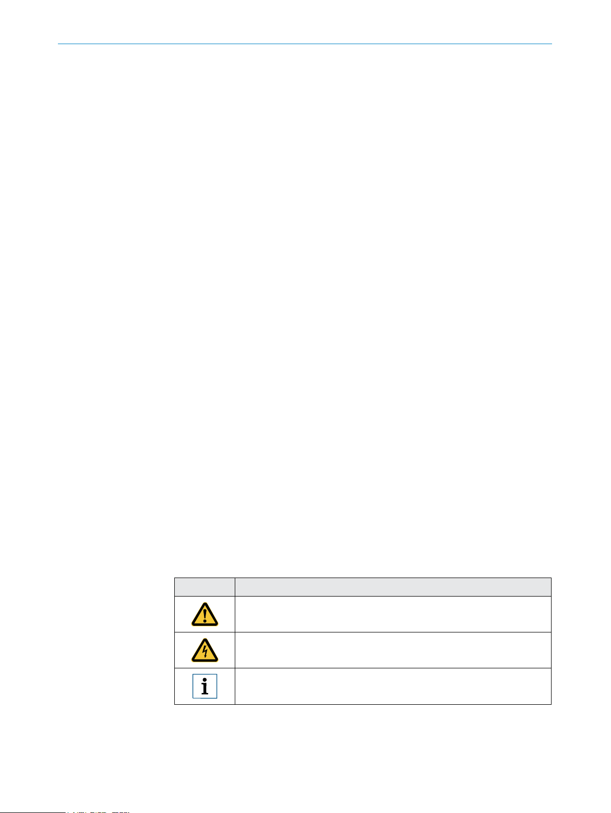
1.4 Symbols used
Symbol Meaning
This symbol indicates a hazard where the product may be damaged by
improper handling.
This symbol refers to a hazard due to electrical charge which may
damage the product.
Subject to change without notice
This symbol precedes a note containing important additional information.
WI180C-PB | PROFIBUS COUPLER8018416.YM10/COMAT/ 2015-03-13 | SICK AG
5
Page 6
1 ABOUT THIS DOCUMENT
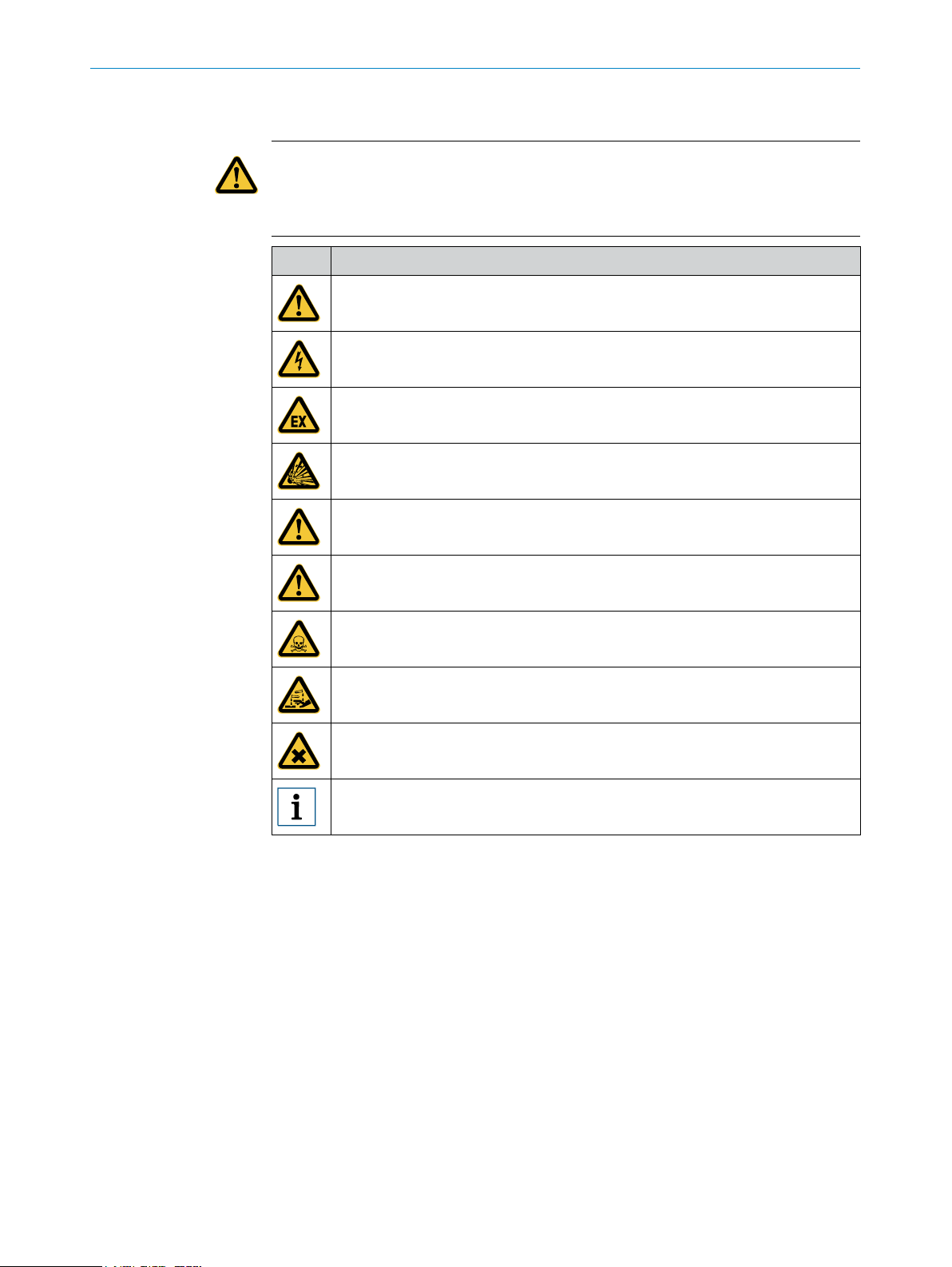
1.5 Symbols and document conventions
WARNING!
A warning indicates a specic or potential danger.
This is intended to protect you against accidents.
Read and follow the warnings carefully!
Symbol Meaning
Danger (general)
Danger of electric shock
Danger in potentially explosive environments
Danger due to explosive substances
Danger due to inammable substances
Danger due to oxidizing agents
Danger due to toxic substances
Danger due to corrosive substances
Danger due to harmful substances
General note with important additional information
6
WI180C-PB | PROFIBUS COUPLER 8018416.YM10/COMAT/ 2015-03-13 | SICK AG
Subject to change without notice
Page 7

1.6 Product information
1ABOUT THIS DOCUMENT
Product name
Device version
Manufacturer
1.7 Further information
www.sick.com
The following information is available on the Internet:
− Other language versions
− Data sheets and application examples
− CAD data of drawings and dimensional drawings
− Certicates (e.g. EU declaration of conformity)
− Current device les
WI180C-PB, WI180C-PB(Sxx)
PROFIBUS
SICK AG
Subject to change without notice
WI180C-PB | PROFIBUS COUPLER8018416.YM10/COMAT/ 2015-03-13 | SICK AG
7
Page 8

2 SAFETY INFORMATION
2 Safety information
2.1 General safety notes
• The mounting, electrical installation and conguration of the device must be carried out by professionally qualied personnel only.
• Before mounting, it is imperative that you familiarize yourself with the operating
instructions for the connected devices.
• When mounting and electrical installation work is being carried out, always comply
with applicable health and safety and environmental regulations.
• The WI180C-PB must not be used outdoors or in areas with ammable/explosive
atmospheres!
• When installing the device, always consider the electrical connected loads.
• Replace faulty or damaged cables and male connectors immediately.
• Replace damaged or faulty couplers immediately.
• When mounting the device, it is imperative that you use suitable mounting equip-
ment and that you consider their specic requirements.
• Ensure a constant power supply to the device within the set parameters.
• Only operate the WI180C-PB within the set operating parameters.
• Regularly check that the WI180C-PB is functioning properly.
• Structural modications to the WI180C-PB are not permitted.
• The WI180C-PB is not designed as a safety product.
2.2 Correct use
Correct use requires that the WI180C-PB is used industrially indoors without any spe-
cic climatic and atmospheric requirements.
Any use outside of the areas mentioned in each case will be considered to be incorrect
use and void any warranty claims against SICK AG.
2.3 Foreseeable misuse
Not taking account of the pin assignment or using an incorrect adapter cable may
damage or destroy the connected PROFIBUS coupler.
Connecting the PROFIBUS coupler to signal or power cables that are too long may lead
to a loss of data and damage to the PROFIBUS coupler.
8
WI180C-PB | PROFIBUS COUPLER 8018416.YM10/COMAT/ 2015-03-13 | SICK AG
Subject to change without notice
Page 9
3 Product description
3.1 Product characteristics
The WI180C-PB is an interface coupler, which can be used to connect connected
devices (e.g. WLL180T) to the PROFIBUS DP. The relevant devices are connected via a
simple plug system on the side of the coupler.
Usually, the entire system is mounted on a mounting rail close to the application.
The coupler supports up to 16 connected devices, which are likewise connected to one
another via the plug system.
Further properties:
− Probus DP-V1 Slave
− Option to communicate via function block (e.g. Siemens SFB52 or SFB53).
Pre-congured SICK function blocks are available to download from www.sick.com.
− Transmission rates of 9.6 Kbits/s–12 Mbit/s
Further specications can be found in the technical data (see page 28).
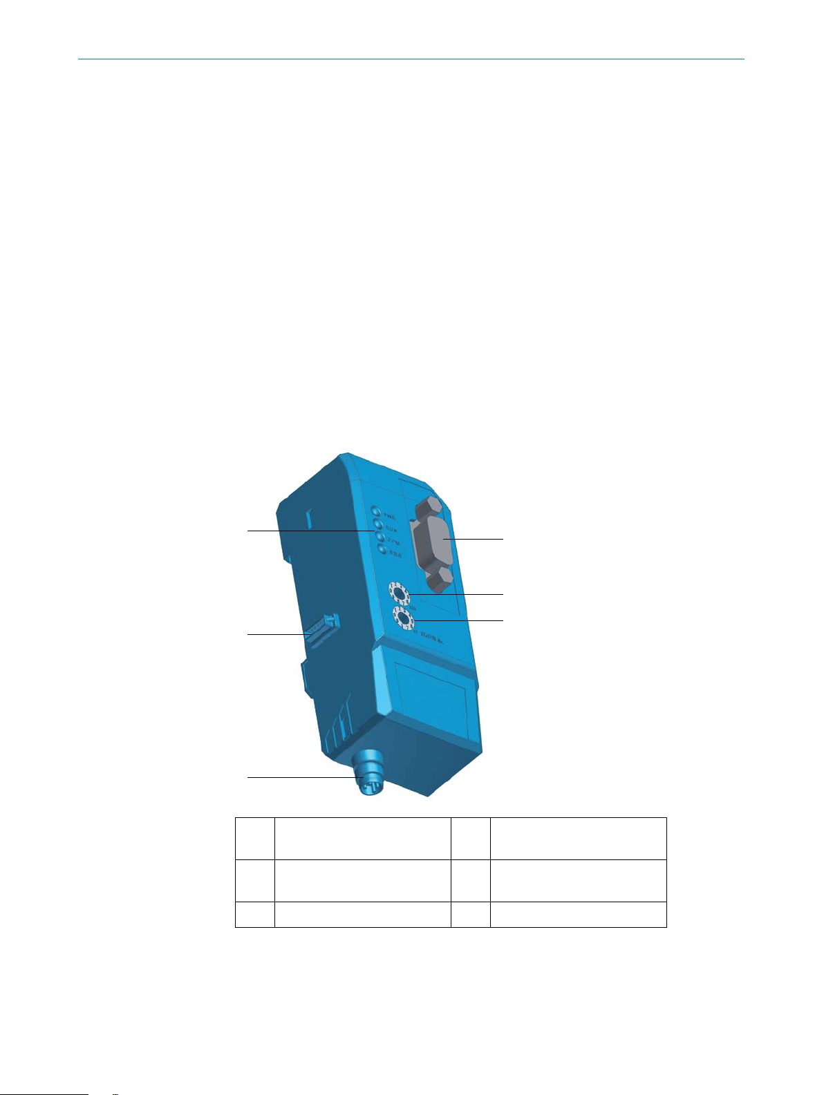
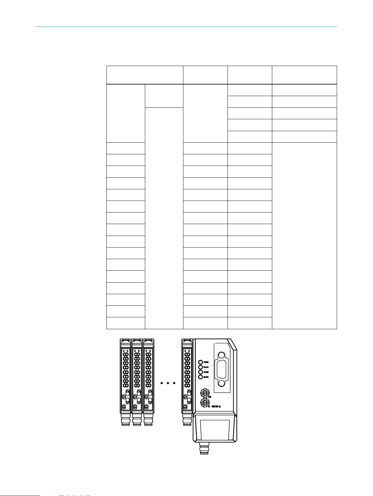
3.2 Setup and function
3PRODUCT DESCRIPTION
Subject to change without notice
1 D-sub connection (RS485),
9-pin, PROFIBUS
2 Switch station no. ×10 5 Bus male connector
3 Switch station no. ×1 6 Status LEDs
4 Power supply connection
(M8), 4-pin
(system bus)
WI180C-PB | PROFIBUS COUPLER8018416.YM10/COMAT/ 2015-03-13 | SICK AG
9
Page 10
3 PRODUCT DESCRIPTION
4
2
1 3
3.3 Interfaces
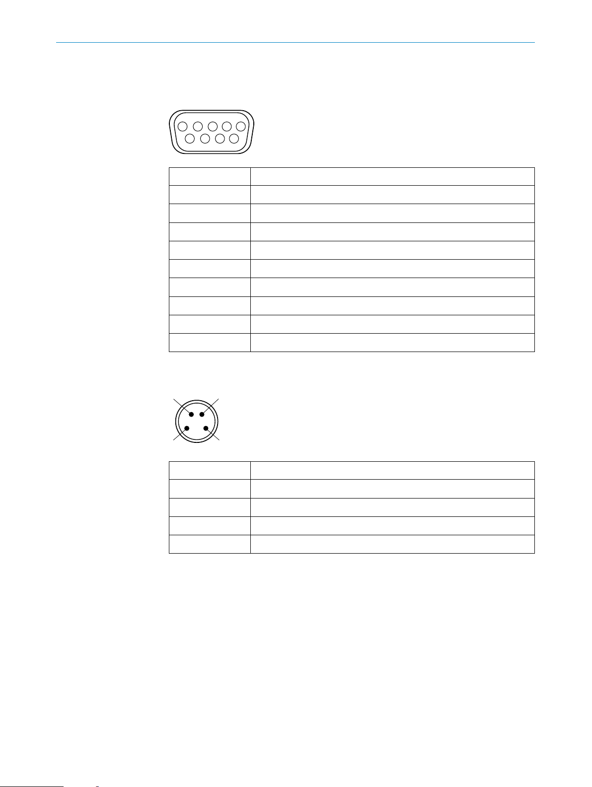
3.3.1 PROFIBUS
Pin Pin assignment
1 Not assigned
2 Not assigned
3 RxD+/TxD+
4 RTS
5 DGND
6 +5 VDC
7 Not assigned
12345
6789
3.3.2 Power supply
8 RxD-/TxD-
9 Not assigned
Pin Pin assignment
1 +12–24 VDC
2 Not assigned
3 GND
4 Not assigned
10
WI180C-PB | PROFIBUS COUPLER 8018416.YM10/COMAT/ 2015-03-13 | SICK AG
Subject to change without notice
Page 11

3.3.3 Grounding
3PRODUCT DESCRIPTION
The WI180C-PB is grounded via the mounting rail by means of a spring contact:
Subject to change without notice
WI180C-PB | PROFIBUS COUPLER8018416.YM10/COMAT/ 2015-03-13 | SICK AG
11
Page 12

4 TRANSPORT AND STORAGE
4 Transport and storage
4.1 Transport
Either transport the WI180C-PB in the original packaging or use a padded transport
container. Make sure that you comply with the maximum permitted environmental conditions (see page 28).
4.2 Storage
If you want to store the WI180C-PB for a relatively long time, pack it as you would for
transport. Make sure that the storage location complies with the permitted environmental conditions (see page 28).
12
WI180C-PB | PROFIBUS COUPLER 8018416.YM10/COMAT/ 2015-03-13 | SICK AG
Subject to change without notice
Page 13

5 Mounting
5.1 Required materials
You need the following additional materials to mount the WI180C-PB.
− grounded mounting rail (pre-mounted)
− pre-assembled cable (max. 30 m) with M8 female connector
(pin assignment see page 10)
− pre-assembled cable for PROFIBUS with D-sub male connector
(pin assignment see page 10)
− one or more signal sources (e.g. WLL180T)
− small slotted screwdriver
5.2 Preparing mounting location
1. Mount a grounded mounting rail in the same area as the application.
2. Lay the two pre-assembled cables so that they can easily be connected to the
connections of the WI180C-PB. If necessary, use cable channels, cable ties and
cable grips.
5MOUNTING
5.3 Scope of delivery
− WI180C-PB
− Quick start instructions
5.4 Mounting procedure
1. Carefully unpack the WI180C-PB.
2. Clamp the WI180C-PB onto the mounting rail, as shown in the image.
3. Clamp the series-connected devices onto the mounting rail as shown in their
mounting instructions.
Subject to change without notice
WI180C-PB | PROFIBUS COUPLER8018416.YM10/COMAT/ 2015-03-13 | SICK AG
13
Page 14

5 MOUNTING
4. Push the series-connected devices onto the 5-pin connection on the left side of the
WI180C-PB. Make sure that the sequence is correct (see the operating instructions
for the relevant device).
5. Fix the connected devices on the mounting rail without any spaces.
5.5 Connecting the device
Note:
Switch the power supply off before you connect or replace the devices.
1. Connect the male D-sub connector for the PROFIBUS connection to the PROFIBUS
connection on the WI180C-PB and secure it using the knurled screws.
2. Connect the female M8 connector on the power supply to the underside of the
WI180C-PB and screw the male connector tight.
14
WI180C-PB | PROFIBUS COUPLER 8018416.YM10/COMAT/ 2015-03-13 | SICK AG
Subject to change without notice
Page 15

6 Commissioning
6.1 Conguration
1. Adjust the PROFIBUS address provided on the two address switches on the front of
the WI180C-PB. Use a small screwdriver to do this.
Note:
The address can be in the range between 01 and 99.
The upper rotary switch "×10" represents a multiple of 10. The lower rotary switch "xy"
represents a value between 0 and 9.
The WI180C-PB must be restarted after every change of address by switching off and
on again, before the new address is transferred.
6COMMISSIONING
2. Call up your PLC/PROFIBUS development or conguration environment.
3. Download the current device le "Sick0E99.GSD" from www.sick.com.
4. Install the device le "Sick0E99.GSD" in your project planning software.
6.2 Switching on
1. Switch on the power supply for the WI180C-PB.
2. Wait approximately two seconds until the WI180C-PB indicates that it is ready
(see page 16).
Subject to change without notice
WI180C-PB | PROFIBUS COUPLER8018416.YM10/COMAT/ 2015-03-13 | SICK AG
15
Page 16

7 OPERATION
7 Operation
7.1 Safety
A few guidelines must be followed to ensure the operational safety of the WI180C-PB:
− Carry out a daily functional check (see page 16).
− If you want to connect devices to the WI180C-PB or remove devices, switch off the
power supply rst.
− Only operate the WI180C-PB under the specied operating conditions
(see page 28).
7.2 Daily thorough check
You should carry out the following functional checks once a day:
− Check the function of the LED indicators.
− Use appropriate status queries to check communication with each of the
connected devices.
7.3 LED status indicators
PWR RUN COM ERR Description
– – – – No power supply
X – – – Power supply established, device is
being initialized
X X – – Initialization completed
X X X – Communication with DP master
established, fault-free function
X ashes
acyclically
X –(100 ms) –/X X/ashes
–/X X/ashes
acyclically
No communication with bus
devices or serious fault
Fault has occurred
acyclically
X –/ashes
–/X X Incorrect conguration
acyclically
X –/ashes
cyclically
X –/X – ashes
–/X ashes
acyclically
Conguration not completed
No communication with DP master
cyclically
Table 1:X: on, –: off
16
WI180C-PB | PROFIBUS COUPLER 8018416.YM10/COMAT/ 2015-03-13 | SICK AG
Subject to change without notice
Page 17
7.4 Addressing the devices
WI180C-PB
Slotnr. 234171
The individual devices are addressed in accordance with the following scheme:
7OPERATION
Slot number Device Example byte
address
Function
1 Output WI180C-PB 0 Teach-in version
2 b0: Reset fault
Input 0 Channel 1 status
2 Channel 2 status
4 External input status
2 Device #1 6 Light value received
3 Device #2 8
4 Device #3 10
5 Device #4 12
6 Device #5 14
7 Device #6 16
8 Device #7 18
9 Device #8 20
10 Device #9 22
11 Device #10 24
12 Device #11 26
13 Device #12 28
14 Device #13 30
15 Device #14 32
16 Device #15 34
17 Device #16 36
Subject to change without notice
Master
Slave 1
Slave 2
Slave 15
WI180C-PB | PROFIBUS COUPLER8018416.YM10/COMAT/ 2015-03-13 | SICK AG
17
Page 18

7 OPERATION
7.5 Communication via PROFIBUS
Function blocks are used for communicating with the connected devices.
Examples:
Standard function blocks:
− Read SFB52 RDREC dataset
− Write SFB52 WRREC dataset
Device-specic SICK function blocks
− Function block for interpreting the acyclic service data
− Parser function for interpreting the cyclic process data
When read, the device's response returns a 4 byte header and the requested data.
A 3 byte header and a 1 byte value for the written data is returned when writing.
7.5.1 Read access
Command telegram
Access type Probus slot Index Dataset length
0x5E (read) 1 byte 1 byte 1 byte
Response telegram
Access type Probus slot Index Dataset length Data
0x5E (read) 1 byte 1 byte 1 byte max. 32 byte
Example
The dealer name of the rst connected device should be read out.
Access type Probus slot Index Dataset length
0x5E 0x06 (Slot 1) 0x05 (5) 0x10 (16)
The response data packet – consisting of 4+16 bytes – contains the requested values:
Byte address Value
18
0 0x53 ("S")
1 0x49 ("I")
2 0x43 ("C")
3 0x4B ("K")
4 0x20 (" ")
5 0x41 ("A")
WI180C-PB | PROFIBUS COUPLER 8018416.YM10/COMAT/ 2015-03-13 | SICK AG
Subject to change without notice
Page 19

7.5.2 Write access
Command telegram
Response telegram
7OPERATION
6 0x47 ("G")
7 0x00 (0)
Note:
The value "0x00" terminates the byte sequence.
Access type Probus slot Index Dataset length Data
0x5F (write) 1 byte 1 byte 1 byte max. 32 byte
Example
Access type Probus slot Index Dataset length
0x5F (write) 1 byte 1 byte 1 byte
An 8 byte tag name should be written to the WI180C-PB.
Value
Access type
Probus slot
Index
Dataset length
Byte address: 0
Byte address: 1
Byte address: 2
Byte address: 3
Byte address: 4
Byte address: 5
0x5F
0x00 (Slot 0)
0x08 (8)
0x08 (8)
0x54 ("T")
0x61 ("a")
0x67 ("g")
0x20 (" ")
0x6E ("n")
0x61 ("a")
Subject to change without notice
Byte address: 6
Byte address: 7
0x6D ("m")
0x65 ("e")
The response packet – consisting of 4 bytes – returns the number of bytes written
(0x08).
WI180C-PB | PROFIBUS COUPLER8018416.YM10/COMAT/ 2015-03-13 | SICK AG
19
Page 20

7 OPERATION
7.6 WI180C-PB index map overview
Index no. Function Details Access Length
(Byte)
Description
0 Product/series b15–12 Manufacturer R 2 1: SICK AG
b11–8 Category 5: Communication unit
b7–0 Family 1: WI180C-PB
1 Product type R 2 1: WI180C-PB
2 Firmware version R 2
3 Protocol version R 2
4 Product revision R 2
5 Vendor name R 2–16 "SICK AG"
6 Product name R 2–32 "WI180C-PB"
7 Product ID R 2–16 "6052566"
8 User ID R/W 2–32 ASCII 32 characters max.
9 Operating status R 2 2: Run
10 Reserved
11 Network prole R 2–32 "Fieldbus PROFIBUS DP adapter
V1"
12...96 Reserved
97 Number of sensors R/W 2 0: no check
1–16: Check number of sensors
98 Error code R/W 2 Clear fault with desired value
99...209 Reserved
210 Warm start W 2 3: execute
211 Reserved
212 Return to factory
W 2 3: execute
settings
213...254 Reserved
255 System, reserved
20
WI180C-PB | PROFIBUS COUPLER 8018416.YM10/COMAT/ 2015-03-13 | SICK AG
Subject to change without notice
Page 21

7.7 WLL180T index map overview (via WI180C-PB)
7OPERATION
Index no. Function Details Access Length
(Byte)
Description
0 Product/series b15–12 Manufacturer R 2 1: SICK AG
b11–8 Category 1: Fiber photoelectric sensor
b7–0 Family 1: WLL180T, 1 output
2: WLL180T, 2 outputs
1 Product type R 2 17: WLL180T
2 Firmware version R 2 0x0200
3 Protocol version R 2 0x0001
4 Product revision R 2 0x0001
5 Vendor name R 2–16 "SICK AG"
6 Product name R 2–32 ASCII 32 characters max.
7 Product ID R 2–16 ASCII 16 characters max.
8 User ID R/W 2–32 Space
9 Operating status R 2 0: Init
1: Idle
2: Run
3: In use by user
10...12 Reserved
13 Parameter bytes R 2 Amount of parameter data to be
saved
14...97 Reserved
98 Error code R/W 2 Clear fault with desired value
99 Reserved
100 Display R/W 2 0: numerical display
1: bar graph
2: percentage display
101 Detection mode R/W 2 0: normal
1: rising signal edge of detected
light
2: falling signal edge of detected
light
3: differential value to the next
(left) unit
102 Teach-in mode CH1 R/W 2 0: 2-point
103 CH2 R/W 2
1: 1-point
2: Transparent
3: Zone
4: Auto
Subject to change without notice
WI180C-PB | PROFIBUS COUPLER8018416.YM10/COMAT/ 2015-03-13 | SICK AG
21
Page 22

7 OPERATION
Index no. Function Details Access Length
(Byte)
Description
104 Response time R/W 2 0: 16 µs
1: 70 µs
2: 250 µs
3: 3 ms
4: 8 ms
105 Transmitting power R/W 2 0: low
1: medium
2: normal
106 Input R/W 2 0: External teach-in
1: Test input
2: Synchronization
3: Reset the counter
4: Master teach-in
5: No function
107 Pushbutton lock R/W 2 0: cancel
1: complete block
2: blocked, external teach-in
108 Operating Mode CH1 R/W 2 0: light
109 CH2 R/W 2
1: dark
110 threshold level CH1 lower limit R/W 2 0...9999
111 CH1 upper limit R/W 2
112 CH2 lower limit R/W 2
113 CH2 upper limit R/W 2
114 Timer setting CH1 R/W 2 0: switch-off delay
115 CH2 R/W 2
1: pulse (one shot)
116 Switch-off delay CH1 R/W 2 0...9999: 0...9999 ms
117 Switch-on delay CH1 R/W 2
-1...-9: 0.1....0.9 ms
118 Switch-off delay CH2 R/W 2
119 Switch-on delay CH2 R/W 2
120...122 Reserved
123 hysteresis R/W 2 1...40%
124...125 Reserved
126 Energy saving mode R/W 2 0: Off
1: energy saving display
127 Display reversal R/W 2 0: normal
1: reversed display
128...199 Reserved
200 Save zero reset W 2 desired value
22
WI180C-PB | PROFIBUS COUPLER 8018416.YM10/COMAT/ 2015-03-13 | SICK AG
Subject to change without notice
Page 23

7OPERATION
Index no. Function Details Access Length
(Byte)
Description
201 Cancel zero reset W 2 desired value
202 1-point teach-in W 2 1: CH1
203 2-point teach-in W 2
2: CH2
204...209 Reserved
210 Warm start W 2 3: execute
211 Return to main menu W 2
212 Return to factory
W 2 3: execute
settings
213...254 Reserved
255 System, reserved
Subject to change without notice
WI180C-PB | PROFIBUS COUPLER8018416.YM10/COMAT/ 2015-03-13 | SICK AG
23
Page 24

8 FAULT INDICATORS
8 Fault indicators
8.1 LED fault indicators
PWR RUN COM ERR Description
X ashes
acyclically
X –(100 ms) –/X X/ashes
X –/ashes
acyclically
X –/X – ashes
Table 2:X: on, –: off
8.2 Error codes
8.2.1 Diagnostic faults for the WI180C-PB
Error code Description
0x06 Number of connected bus devices was reduced
0x09 Different number of registered and actually connected bus devices
0x0A Timeout during communication with bus device
0x0B Internal communication fault
–/X X/ashes
acyclically
No communication with bus
devices or serious fault
Fault has occurred
acyclically
–/X X Incorrect conguration
No communication with DP master
cyclically
0x0C Unexpected response from internal bus
24
WI180C-PB | PROFIBUS COUPLER 8018416.YM10/COMAT/ 2015-03-13 | SICK AG
Subject to change without notice
Page 25

8.2.2 Diagnostic faults for the WLL180T
Error code Description
0x12 End of the data
0x13 Attempt to write blocked parameters
0x14 Teach different output channel
0x15 Attempt to apply 2-point teach to a mode that does not support it
0x16 Forbidden parameter value for warm start or initialization
0x17 Parameter value outside of permitted limits
0x18 Index value outside of permitted limits
0x19 Attempt to teach counter mode
0x1B Received light value too weak during teach-in
0x1C Received light value too high during teach-in
0x1D Difference in received light values between rst and second point too
small during 2-point teaching
8FAULT INDICATORS
8.2.3 Communication error
Error code Description
0xB0 Forbidden index value
0xB1 Forbidden data length
0xB2 Forbidden slot number
0xB6 Access denied
0xB8 Defective parameters
Subject to change without notice
WI180C-PB | PROFIBUS COUPLER8018416.YM10/COMAT/ 2015-03-13 | SICK AG
25
Page 26

9 DECOMMISSIONING
9 Decommissioning
9.1 Dismantling
1. Switch off the power supply for the WI180C-PB.
2. Disconnect the male connector of the power supply and the PROFIBUS male
connector.
3. Detach the mountings for the connected devices.
4. Disconnect the connected devices from the bus male connector of the WI180C-PB.
5. Carefully push up the WI180C-PB until you can tip it forwards.
9.2 Disposal
6. Remove the WI180C-PB from the mounting rail.
At the end of its service life, the WI180C-PB must be disposed of correctly as waste
electronics. Take the regulations in your country into account also.
26
WI180C-PB | PROFIBUS COUPLER 8018416.YM10/COMAT/ 2015-03-13 | SICK AG
Subject to change without notice
Page 27

10 Technical data
10
10.1 Dimensional drawings
10TECHNICAL DATA
25.3
39
38.2
33.2
18.835
27.1
92
102.55
37.9
Subject to change without notice
10.4
No. Description No. Description
1 PWR-LED 5 Switch station no. (x1 and x10)
2 RUN-LED 6 Power supply connection (M8),
4-pin
3 COM-LED 7 Bus male connector (system bus)
4 ERR-LED 8 D-sub connection (RS-485), 9-pin,
PROFIBUS
WI180C-PB | PROFIBUS COUPLER8018416.YM10/COMAT/ 2015-03-13 | SICK AG
27
Page 28

10 TECHNICAL DATA
10.2 Technical data
Description Value
Electrical
Supply voltage 12 – 24 VDC ± 10%
Power consumption 2 W
Switch-on delay (WI180C-PB) 500 ms
Switch-on delay (overall system) 2000 ms
Prole PROFIBUS DP-V1
Maximum number of modules to be con-
16
nected
Transmission rates in kbit/s 9.6/19.2/45.45/93.75/187.5/500/
1.500/3.000/6.000/12.000
Maximum distance between nodes 1.200 m @ 9.6 – 93.75 kbit/s
1.000 m @ 187.5 kbit/s
400 m @ 500 kbit/s
200 m @ 1.500 kbit/s
100 m @ 3.000 – 12.000 kbit/s
Process data 2x output, 1x input, 14 bit received light
Asynchronous data Fieldbus index map, see page 20 ff.
Transmission interface RS-485
LEDs PWR, RUN, COM, ERR (3x green, 1x red)
EMC
Product safety
Mechanical
Power supply Male M8 plug connector, 4-pin
Other interfaces Male bus connector, 5-pin, internal
system bus
D-sub, 9-pin, PROFIBUS
Noise immunity (Length of cable ≤30 m) in accordance with EN 61000-6-2/
EN 61131-2
Emission in accordance with EN 55011, class A
Protection class 3
Short-circuit protection in accordance with VDE 0160
Protection category IP50
Sensitivity to vibrations IEC 68, 10 – 55 Hz
Shock resistance IEC 68, 500 m/s² (~50 G)
Housing material Polycarbonate
Dimensions (HxWxD) in mm 39.2 x 102.55 x 39
Connections M8, 4-pin, power supply
D-sub, 9-pin, PROFIBUS
Male bus connector, 5-pin, bus con-
nector
Environmental
parameters
28
WI180C-PB | PROFIBUS COUPLER 8018416.YM10/COMAT/ 2015-03-13 | SICK AG
Air humidity (operation/storage) 35 – 85% relative humidity
Subject to change without notice
Page 29

Temperature range (storage) -40 – +70 °C
10TECHNICAL DATA
Temperature range (Operation, ≤3 connected
devices)
Temperature range (Operation, ≤8 connected
devices)
Temperature range (Operation, ≤16 connected
devices)
10.3 Ordering information, accessories
Part number Type Description
6009870 D0L-0804-G02M Female connector, M8, 4-pin, straight, 2 m cable
6009872 D0L-0804-G05M Female connector, M8, 4-pin, straight, 5 m cable
6009871 D0L-0804-W02M Female connector, M8, 4-pin, angled, 2 m cable
6009873 D0L-0804-W05M Female connector, M8, 4-pin, angled, 5 m cable
5313011 BF-EB01-W190 End piece for mounting rails
-25 – +55 °C
-25 – +50 °C
-25 – +45 °C
Subject to change without notice
WI180C-PB | PROFIBUS COUPLER8018416.YM10/COMAT/ 2015-03-13 | SICK AG
29
Page 30

30
WI180C-PB | PROFIBUS COUPLER 8018416.YM10/COMAT/ 2015-03-13 | SICK AG
Subject to change without notice
Page 31

Subject to change without notice
WI180C-PB | PROFIBUS COUPLER8018416.YM10/COMAT/ 2015-03-13 | SICK AG
31
Page 32

8018416.YM10 /2015-03-13 ∙ COMAT/ITL (2015-03) ∙ USmod 4c int44
Australia
Phone +61 3 9457 0600
1800 334 802 – tollfree
E-Mail sales@sick.com.au
Austria
Phone +43 (0)22 36 62 28 8-0
E-Mail office@sick.at
Belgium/Luxembourg
Phone +32 (0)2 466 55 66
E-Mail info@sick.be
Brazil
Phone +55 11 3215-4900
E-Mail marketing@sick.com.br
Canada
Phone +1 905 771 14 44
E-Mail information@sick.com
Czech Republic
Phone +420 2 57 91 18 50
E-Mail sick@sick.cz
Chile
Phone +56 2 2274 7430
E-Mail info@schadler.com
China
Phone +86 4000 121 000
E-Mail info.china@sick.net.cn
Denmark
Phone +45 45 82 64 00
E-Mail sick@sick.dk
Finland
Phone +358-9-2515 800
E-Mail sick@sick.fi
France
Phone +33 1 64 62 35 00
E-Mail info@sick.fr
Gemany
Phone +49 211 5301-301
E-Mail info@sick.de
Great Britain
Phone +44 (0)1727 831121
E-Mail info@sick.co.uk
Hong Kong
Phone +852 2153 6300
E-Mail ghk@sick.com.hk
Hungary
Phone +36 1 371 2680
E-Mail office@sick.hu
India
Phone +91–22–4033 8333
E-Mail info@sick-india.com
Israel
Phone +972-4-6881000
E-Mail info@sick-sensors.com
Italy
Phone +39 02 27 43 41
E-Mail info@sick.it
Japan
Phone +81 (0)3 5309 2112
E-Mail support@sick.jp
Malaysia
Phone +603 808070425
E-Mail enquiry.my@sick.com
Netherlands
Phone +31 (0)30 229 25 44
E-Mail info@sick.nl
New Zealand
Phone +64 9 415 0459
0800 222 278 – tollfree
E-Mail sales@sick.co.nz
Norway
Phone +47 67 81 50 00
E-Mail sick@sick.no
Poland
Phone +48 22 837 40 50
E-Mail info@sick.pl
Romania
Phone +40 356 171 120
E-Mail office@sick.ro
Russia
Phone +7-495-775-05-30
E-Mail info@sick.ru
Singapore
Phone +65 6744 3732
E-Mail sales.gsg@sick.com
Slovakia
Phone +421 482 901201
E-Mail mail@sick-sk.sk
Slovenia
Phone +386 (0)1-47 69 990
E-Mail office@sick.si
South Africa
Phone +27 11 472 3733
E-Mail info@sickautomation.co.za
South Korea
Phone +82 2 786 6321
E-Mail info@sickkorea.net
Spain
Phone +34 93 480 31 00
E-Mail info@sick.es
Sweden
Phone +46 10 110 10 00
E-Mail info@sick.se
Switzerland
Phone +41 41 619 29 39
E-Mail contact@sick.ch
Taiwan
Phone +886 2 2375-6288
E-Mail sales@sick.com.tw
Thailand
Phone +66 2645 0009
E-Mail tawiwat@sicksgp.com.sg
Turkey
Phone +90 (216) 528 50 00
E-Mail info@sick.com.tr
United Arab Emirates
Phone +971 (0) 4 88 65 878
E-Mail info@sick.ae
USA/Mexico
Phone +1(952) 941-6780
1 (800) 325-7425 – tollfree
E-Mail info@sick.com
Vietnam
Phone +84 8 62920204
E-Mail Ngo.Duy.Linh@sicksgp.com.sg
More representatives and agencies
at www.sick.com
SICK AG | Waldkirch | Germany | www.sick.com
 Loading...