

Page 1
04 06
Amplifier Unit WI130
Australia
Phone +61 3 9497 4100
E-Mail: sales@sick.com.au
Belgium/Luxembourg
Phone +32 (0)2 466 55 66
E-Mail: info@sick.be
Brasil
Phone +55 11 5091-4900
E-Mail: sac@sick.com.br
Ceská Republika
Phone +420 2 57 91 18 50
E-Mail: sick@sick.cz
China
Phone +852-2763 6966
E-Mail: ghk@sick.com.hk
Danmark
Phone +45 45 82 64 00
E-Mail: sick@sick.dk
Deutschland
Phone +49 (0)2 11 53 01-0
E-Mail: info@sick.de
España
Phone +34 93 480 31 00
E-Mail: info@sick.es
France
Phone +33 1 64 62 35 00
E-Mail: info@sick.fr
Great Britain
Phone +44 (0)1727 831121
E-Mail: info@sick.co.uk
India
Phone +91 –22– 2822 7084
E-Mail: info@sick-india.com
Italia
Phone +39 02 27 40 93 19
E-Mail: info@sick.it
Japan
Phone +81 (0)3 3358 1341
E-Mail: info@sick.jp
Nederlands
Phone +31 (0)30 229 25 44
E-Mail: info@sick.nl
We reserve the right to make changes without prior notification
For further information regarding the configuration menu and
teaching function please take note of the handbook. Available on
the internet at www.sick.com or from your contact person at SICK.
Safety Precautions
Carefully read and understand the safety precautions before operation.
The important information is provided to protect your health and property.
Do not apply any other installing or operating procedure other than that described
in this manual.
Meanings of Safety Symbols
Indicates a possible hazard that may result in death,
WARNING
CAUTION
serious injury, or serious property damage if the product is used without observing the stated instructions.
Indicates a possible hazard that may result in
personal injury or property damage if the product is
used without observing the stated instructions.
Mandatory Requirements
WARNING
CAUTION
This product is not an explosion-proof construction.
Do not use the product under flammable, explosive
gas or liquid environment.
Do not use the product in water.
Do not disassemble, repair, or convert the product.
Failure to do this may cause failure, fire, or electric
shock.
Operate within the rated range.
This product cannot be used as a safety device to
protect human body.
Use of controls or adjustments or performance of
procedures other than those specified herein may
result in hazardous radiation exposure.
Norge
Phone +47 67 81 50 00
E-Mail: austefjord@sick.no
Österreich
Phone +43 (0)22 36 62 28 8-0
E-Mail: of fice@sick.at
Polska
Phone +48 22 837 40 50
E-Mail: info@sick.pl
Republic of Korea
Phone +82-2 786 6321/4
E-Mail: kang@sickkorea.net
Republika Slowenija
Phone +386 (0)1-47 69 990
E-Mail: of fice@sick.si
Russia
Phone +7 95 775 05 30
E-Mail info@sick-automation.ru
Schweiz
Phone +41 41 619 29 39
E-Mail: contact@sick.ch
Singapore
Phone +65 6744 3732
E-Mail: admin@sicksgp.com.sg
Suomi
Phone +358-9-25 15 800
E-Mail: sick@sick.fi
Sverige
Phone +46 8 680 64 50
E-Mail: info@sick.se
Taiwa n
Phone +886 2 2365-6292
E-Mail: sickgrc@ms6.hinet.net
Türkiye
Phone +90 216 388 95 90 pbx
E-Mail: info@sick.com.tr
USA/Canada/México
Phone +1(952) 941-6780
E-Mail: info@sickusa.com
More representatives and agencies
in all major industrial nations at
www.sick.com
2tni ZB 006 · eetnaraug yna tneserper ton od atad lacinhcet dna serutaef tcudorp deificeps ehT
Operational Precautions
CAUTION
Use the specified sensor head to connect this
product. Any use other than specified will cause
accident or product damage.
It is dangerous to wire or attach/remove the
connector with the power on. Make sure to turn
off the power before operation.
Make sure to use the product with the
protective cover attached and closed.
Installing in the following places may result in
malfunction:
1. A dusty or steamy place
2. A place generating corrosive gas
3. A place directly receiving scattering water
or oil.
4. A place suffered from heavy vibration or
impact.
The product is not designed for outdoor use.
Do not use the sensor in transient state after
power on (approx. 100 ms).
Do not wire with the high voltage cable or the
power line.
malfunction by induction or damage.
The sensor performance or digital display values
may depend on the individual units or the condition
of detected product.
Failure to do this will cause
Specification
Model
Cable type
M8 connector type
Master
WI130T-P/N720
-
- WI130T-P/N340
Adaptable sensor head
Advanced Model (2CH)
Power source, voltage
12 to 24 V DC ± 10 % including a ripple
45 mA or less / 24 VConsumption current
60µs / 500µs / 2ms (Fast/Standard/Long)Response time
Control output
Indicator light
Digital display
Timer function
Setting input/output
Operating temperature/humidity
Store temperature/humidity
Shock resistance
Load current: 100 mA or less, Residual voltage:1.8 V or less
Laser emission indicator light: Green, Output Indicator light: Orange (1·2CH)
Teaching indicator light: Red, Channel indicator light: Green (1·2CH)
Current output:4 to 20 mAAnalog output
External input setting
(1 point teaching, synchronizing
input, floodlight off, counter reset)
Output setting
(
2CH output + Alarm output
*1
10 to 55 Hz Double amplitude 1.5 mm 2 hours for each direction of X, Y, and Z
NPN / PNP Open collector
7-segment 8-digit display
OFF, On delay, Off delay, One-shot
-25 to +55°C / 35 to 85 % RH (No freezing)
-40 to +70°C / 35 to 85 % RH (No condensation)
PC: Case and coverMaterial
Weight (including the codes)
*1 Operating temperature may differ according to the number of connection.
See as follows:
1 to 3 machine(s): -25 to +55°C
4 to 8 machines: -25 to +50°C * When not using analog output.
Cable type: 65 g, M8 connector type: 30 g
Standard Model (1CH)
W130-Series
1 ms to 9 sTimer time
External input setting
(1 point teaching, synchronizing
input, floodlight off, counter reset)
)
IP50Protective category
Master
Input/Output Schematic
NPN PNP
• WI130T-N720 • WI130T-P720
Protective
Protective
circuit
circuit
Main circuit
• WI130T-N340
Protective
circuit
Main circuit
Brown
12 to 24 V DC
Load
Load
Black
Control output 1 CH
White
Control output 2 CH
Blue
0 V
Black and
Analog output
white
Analog GND
Gray
External input
1
Brown
12 to 24 V DC
Load
4
Black
Control output 1 CH
2
Gray
External input
3
Blue
0 V
Protective
Protective
circuit
circuit
Main circuit
• WI130T-P340
Protective
circuit
Main circuit
Brown
Black
White
Load
Load
Blue
Black and
white
Gray
Brown
Black
Gray
Load
Blue
12 to 24 V DC
Control output 1 CH
Control output 2 CH
0 V
Analog output
Analog GND
External input
1
12 to 24 V DC
4
Control output 1 CH
2
External input
3
0 V
Pin layout
WI130T-P/N340
External input
12 to 24 V DC
Control output
2
4
1
3
0 V
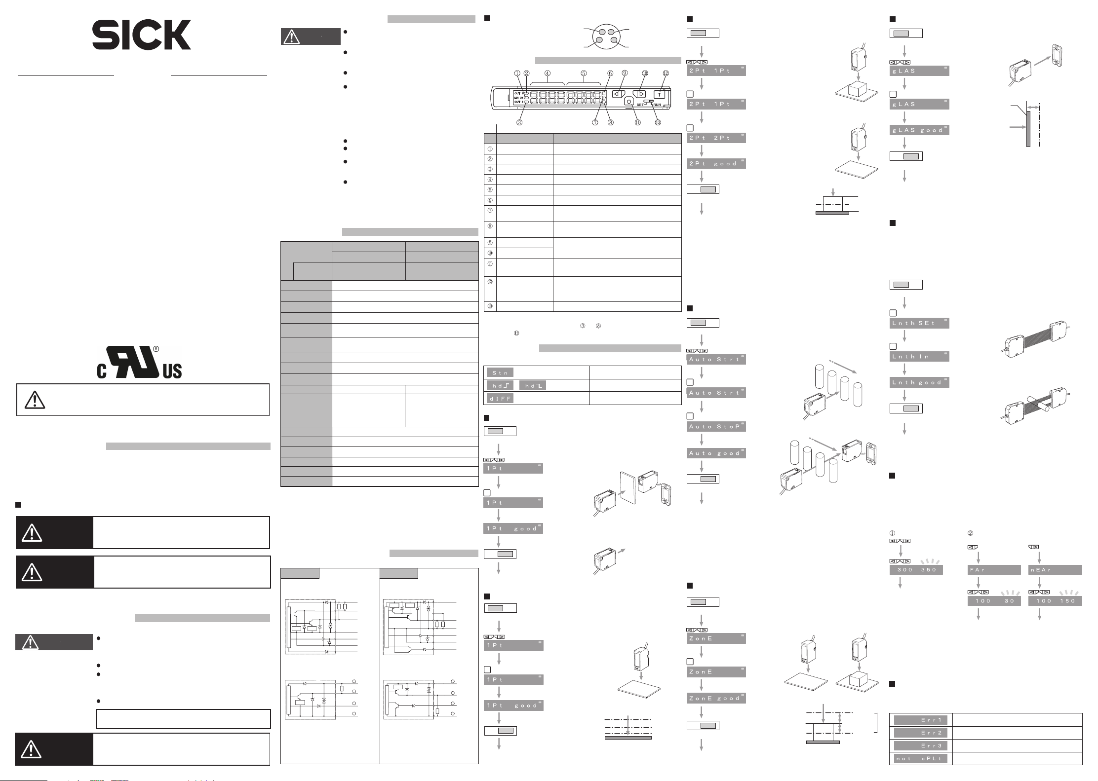
Each Part
NameNo.
Laser emission indicator light
1 CH output indicator light
2 CH output indicator light
Main monitor (Red)
Sub monitor (Green)
Teaching mode indicator light
Valid channel indicator light
(1 CH)
Valid channel indicator light
(2 CH)
UP button
DOWN button
Mode button
Teaching button
SET/RUN selection switch
Turns on while the amplifier is powered.
Turns on when the output of 1 CH is ON.
Turns on when the output of 2 CH is ON.
Displays light intensity, function, and the number of counts.
Displays the threshold, function selection, and the number of counts.
Turns on in the Teaching mode.
Keeps turning ON when the monitor display value,
adjustment, and the function setting are valid to 1 CH.
Keeps turning ON when the monitor display value,
adjustment, and the function setting are valid to 2 CH.
RUN mode: Displays or changes the threshold.
Function mode: Selects the function or changes the numerical values.
RUN mode: Switches to the Function mode. (0.5 s ≥)
Function mode: Fix the selection.
RUN mode: Switches the channel.
Function mode: Returns to RUN mode or performs scaling.
Set mode: Run the teaching.
Switches between Teaching mode and RUN mode.
* The button function varies in each mode: RUN mode, Function mode, and SET mode.
* WI130T-P/N340 are 1 output (1 CH) type, and do not turn on.The channel
switching of also becomes invalid.
Funct ion
Adjustment
The available teaching depends on "5.3 Detection Mode setting." Refer to below:
(Standard detection) All teachings are valid.
(Edge detection) No teaching is valid.
/
(Differential detection) Only one point teaching is valid.
Setting Maximum Sensitivity
SETRUN
T
SETRUN
The threshold flashes and the
display returns to normal.
SETRUN
T
SETRUN
The threshold flashes and the
display returns to normal.
Switch to SET.
Select the one point teaching.
Press the teaching button.
Switch to RUN.
One Point Teaching
Switch to SET.
Select the one point teaching.
Press the teaching button.
Switch to RUN.
Transmission type
Regressive Reflection type: Perform
adjustment when there is an object.
Reflection type: Perform adjustment
when there is no object.
Reflection type: Perform adjustment
with the background without object.
FaSt +15%Threshold
Stnd +5%
Long +1%
Set the threshold against the amount of
received light.
(Depends on the response speed setting.)
Two Points Teaching
SETRUN
T
T
SETRUN
The threshold flashes and the
display returns to normal.
Switch to SET.
Select the two points teaching.
1st point: Press the teaching button.
2nd point: Press the teaching button.
Switch to RUN.
Auto Teaching
SETRUN
T
T
SETRUN
The threshold flashes and the
display returns to normal.
Switch to SET.
Select the auto teaching.
Start: Press the teaching button.
End: Press the teaching button.
Switch to RUN.
Zone Teaching
SETRUN
T
SETRUN
The threshold flashes and the
display returns to normal.
Switch to SET.
Select the zone teaching.
Press the teaching button.
Switch to RUN.
Reflection type
1st: Perform adjustment when there
is an object.
2nd: Perform adjustment with the
background without object.
10%
10%
1st
2nd
Near
Upper limit
Lower limit
Far
Threshold
Set the threshold at the center
between the 1st and the 2nd points.
Reflection, Transmission, Regressive
Reflection type
Start and End: Perform adjustment
while the object is passing.
Reflection type: Perform adjustment
with the background without object,
and when there is an object.
Threshold
Threshold
Set the zone (detection range) to ±10 %
against the amount of received light.
Teaching Transparent Object
SETRUN
Switch to SET.
Press the teaching button.
T
Switch to RUN.
SETRUN
The threshold flashes and the
display returns to normal.
Rotating reflection type: Perform
when there is no object.
Reflection side
of reflector
-10%
Threshold
Set the threshold to -10 % against the
amount of received light.
Teaching Length Measurement
Valid only when the length measurement function is set. Allows to
determine the size or the length of object.
* Not displayed on the teaching mode menu unless the application of length
measurement is selected in the detection mode setting.
* Teaching length measurement or length measurement mode does not measure
the actual length of object accurately.
SETRUN
Switch to SET.
SET: Press the teaching button.
T
IN: Press the teaching button.
T
Transmission type (In length
measurement)
SET: Press the teaching button when
there is no object with the flood light
and the light receiver facing each
other.
IN: Press the teaching button when
there is an object.
Switch to RUN.
SETRUN
The upper limit flashes and
the display returns to normal.
Manual Adjustment
Pressing the UP/DOWN button in the RUN mode flashes the threshold.
It indicates that adjustment is possible. Adjust to any value using the
UP/DOWN button.
When using the zone teaching, the threshold of upper/lower limit can
be set individually.
Normal
Automatically returns to
the normal display 5
seconds after completion of
the setting (no operation).
* No operation state for 5 seconds during setting automatically returns the display
to normal as well.
When using zone teaching
Setting Lower Limit (Far)
Automatically returns to the normal display
5 seconds after completion of the setting
(no operation).
Setting Upper Limit (Near)
Error Display in Teaching
An error message is displayed in the event of error during adjustment.
Refer to the table below for readjustment.
Indicates shortage of light intensity or no
Zone
difference of light intensity.
Indicates a sampling error in teaching of a moving object.
Indicates a calculation error.
Indicates that the teaching is interrupted.
Page 2
Press the mode button.
1. Operation setting
TOP
2. Response speed setting
TOP
3. Timer setting
TOP
4. Sensitivity correction
setting
TOP
5. Detailed setting
(Expert mode)
TOP
6. Initialization setting
(Initial reset)
TOP
7. End of setting
Returns to the normal display.
Select an operation mode.
Select by using and fix by .
screen returns to the TOP of Operation setting.
ON when light comes in.
ON when light is blocked.
* The timer can be set individually for 1CH and 2CH.
Select a response speed.
Select by using and fix by .
The screen returns to the TOP of Response
speed setting.
High accuracy setting 2 ms
Standard setting 500 µs
Fastest setting 60 µs
Select a timer and the time.
Select by using and fix by .
OFF moves to the TOP of Timer setting and
others move to the Timer setting.
Timer off
Off delay timer
On delay timer
One shot timer
Timer Time Setting 1-9000 (1 ms - 9 s)
is for time changing, is for digit
change, and is to fix. Then the screen
returns to Timer setting TOP.
* The timer can be set individually for 1CH and 2CH.
* Parallel use of On delay timer and Off delay timer in
the same channel same channel is not possible.
Correct to the optimal value when sensitivity is
not enough.
Turn on using . The progressing status is
displayed in bar chart. After the end, the
screen returns to the TOP of Sensitivity
correction.
* Settings are only for turning on (ON) or turning off
(OFF).
Moves to the Detailed setting menu.
T
Turn on the sensitivity correction.
Turn off the sensitivity correction.
A
Initialize all settings.
Select by using and fix by .
The screen returns to the TOP of
Initialization setting.
Not initialize
Initialize
Initializing changes all settings to the factory default.
Precautions for Function Setting
which concomitant use is not allowed, from the displayed items. This does not
indicate any failure.
specified.
selected, and displays "d" when the down-counter is selected.
CH and 2 CH are changed when the setting of each function is modified.
connected to the right side from the cable connector of operated amplifier unit.
The
A
5.1 Zero-reset setting
TOP
5.2 Display setting
TOP
5.3 Detection mode setting
TOP
5.4 Counter setting
TOP
5.5 Output setting
TOP
5.6 External input setting
TOP
5.7 Analog function setting
TOP
5.8 All copy setting
TOP
BC
Set the displayed value on the main monitor to "0."
Select by using and fix by .
The screen returns to the TOP of Zero reset
setting.
Turn off Zero reset.
Turn on Zero reset.
Select a display method of normal main sub monitor.
Select by using and fix by .
The screen returns to the TOP of Display
setting.
Displayed in numeric display.
Displayed in bar display.
Displayed in percent (%) display.
Displayed in normal count display.
Displayed in total count display.
No display.
"cnt" or "tcnt" can be select only when the counter
function is valid.
Select a detection method from the list below:
Select by using and fix by .
The screen returns to the TOP of Detection
mode setting.
Sets to the normal detection.
Sets to the rising edge detection.
Sets to the trailing edge detection.
Sets to the differential detection.
Detects for length measurement.
* Make sure to connect two amplifier units before
differential detection.
Select counter function ON/OFF and a increasing/
decreasing direction of value.
Select by using and fix by .
OFF moves to the TOP of Counter setting,
and the others to number of count setting.
Counter off
Sets the count value to the
increasing direction.
Sets the count value to the
decreasing direction.
Number of count setting 0 - 9999999
is for count change, is for digit
change, and is to fix. The screen returns
to the Timer Setting TOP.
Select an output method of 1CH and 2CH.
Select by using and fix by .
The screen returns to the TOP of Output setting.
* WI130T-P/N340 do not allow these settings.
Select an assignment of external input.
Select by using and fix by .
The screen returns to the TOP of External
input setting.
* WI130T-P/N340
Moves to the analog function setting
detail menu.
T
1, 2CH: Control output
1CH: Control output,
2CH: Alarm output
Sets to the external teaching input.
Sets to the laser off input.
Sets to the synchro input.
(available only in use of length
measurement function)
Sets to the counter value reset
input.
D
Copy the setting to the connected amplifier units.
Select by using and fix by .
The screen returns to the TOP of All copy setting.
Does not copy.
TIP
Makes copy.
The key-locked amplifier unit setting is not
modified.
BC
Set the displayed value on the main monitor of
5.9 All zero-reset setting
TOP
5.10 All one point teaching
setting
TOP
5.11 Length measurement
standard value setting
TOP
5.12 End of Detail Setting
(Expert mode)
Returns to the TOP of Detail Setting (Expert mode).
connected amplifier units to 0.
TIP
The key-locked amplifier unit is not reset.
A single unit operates the teaching of all connected
amplifier units.
TIP
The key-locked amplifier unit does not
perform teaching.
Select a width of flood line of sensor head.
Valid only for WSE130L-52/54.
D
5.7.1 Analog output setting
TOP
5.7.2 Span setting
TOP
5.7.3 Output clamp hold
setting
TOP
5.7.4 Average counter setting
TOP
5.7.5 Hold setting
TOP
5.7.6 End of Analog function
setting
Returns to the TOP of Analog function setting.
Select either read out or turn off the analog output.
Set the slant of output.
Slant setting
* Full scale of the default is as follows:
Transmission, Regressive reflection, or Reflection type:
Transmission type and in setting length measurement:
0 - 3000 (Received light = Line width)
Select a measurement value state when
measurement is impossible.
Select a number of times of sampling.
Select a hold state.
* Settable only when the length measurement function
Select by using and fix by .
The screen returns to the TOP of all zero-reset setting.
Does not perform zero-reset.
Performs all zero-reset.
Select by using and fix by .
The screen returns to the TOP of All
one-point teaching setting.
Does not perform teaching.
Performs all one point teaching.
Select by using and fix by .
The screen returns to the TOP of Length
measurement standard value setting.
Turns off the setting.
Sets to 3000.
Select by using and fix by .
The screen returns to the TOP of Analog
output setting.
Turns off.
Reads out.
Select by using and fix by .
The screen moves to each detail setting.
Set 4 mA.
Set 20 mA.
is for slant change, is for digit
change, and is to fix. The screen returns
to the TOP of Span setting.
After end of 4A setting, the screen moves to 20A setting.
0 - 4000 (Amount of received light)
Select by using and fix by .
The screen returns to the TOP of Output
clamp hold setting.
Select by using and fix by .
The screen returns to the TOP of Average
counter setting.
Select by using and fix by .
The screen returns to the TOP of Hold setting.
is in use.
T
Set the output to approx. 24 mA.
Hold just before measurement
becomes impossible.
Set.
Average counter
1/4/8/16/32/64/128/
256/512/1024/2048
Normal measurement
Peak hold
Bottom hold
Peak to Peak hold
Switching Channel
T
Pressing the button during the RUN mode allows switching. At the same
time the channel indicator light switches.
T
* WI130T-P/N34/33/32/12 cannot be switched as they have a single output (1CH).
Returning to Normal Display with One Button
Pressing the button for 2 seconds or more in setting each function enables
T
to return to the normal display (RUN mode) without using Eit (Exit).
* Invalid while setting the timer time, number of count, or span slant.
Key Lock
Cancels all the operations. Useful to prevent accidental operation.
Hold down the but tons for 2 seconds or more simultaneously in the
RUN mode. Operate in the same way to cancel as well.
In locking When cancelled
TIP
During key lock, no command such as all teaching/copy is accepted from other
sensors.
Setting Amplifier Unit
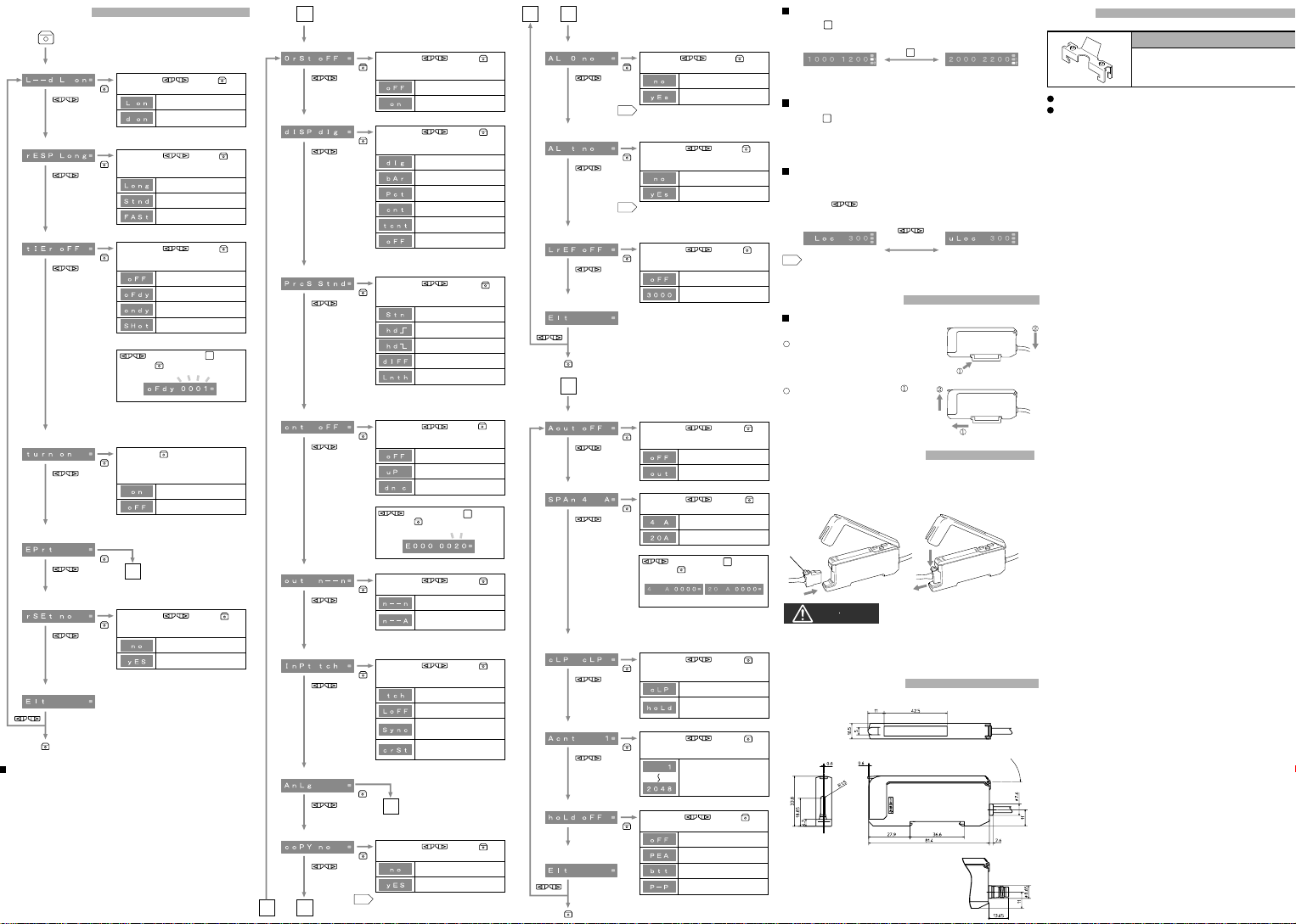
Attaching and Removing to/from DIN rail
Attachment of Amplifier Unit
Hook the claw on the connecting side of
sensor head to the DIN rail. Then press
down the hook until it locks.
Removal of Amplifier Unit
Pushing the unit to the direction of ,
hold up the connecting side of sensor
head and remove the unit.
Connecting Sensor Head
Open the protective cover and plug the connector into the amplifier unit with
the lock lever facing up.
Make sure that it clicks.
When removing, hold down the lock lever and pull out the connector.
Lock Lever
CAUTION
• Do not attach any sensor head other than the specified one (W130L
Series).
• When removing the connector, do not pull on the cable.
Failure to do so will break the cable or damage the product.
Dimensional drawing
• WI130-P/N
340/720
• WI130-P/N340
(Unit: mm)
Maximum aperture 180°
Options
End Unit
BEF-BE01-W190 (2 pcs)
The product specification may change without notice for improvement.
For any inquiry, please contact the manufacture/vendor below.
 Loading...