

Page 1
V4000 Press Brake sensor system
for protecting the press brake
OPERATING INSTRUCTIONS
GB
Page 2

Operating instructions
V4000 PB
This document is protected by copyright. The SICK AG company retains this right. Reproducing this document in
whole or part is only permissible within the limits of the statutory regulations of copyright law. Modifying or
abridging the document is impermissible without the express written permission of from the SICK AG company.
2 © SICK AG • Industrial Safety Systems • Germany • All rights reserved 8010505/TL63/2009-11-27
Page 3

Insert
V4000 PB
Update
Update
Please take note of the following updates to this document!
a
WARNING
Based on Machinery Directive 2006/42/EC, we have added the following supplementary
data or change notices on our product to the following document.
Scope
This document is an original document.
Cited standards and directives
The standards and directives cited in these operating instructions might have changed.
The following list indicates the standards and directives that might have been cited and
their successive versions.
Kindly replace the standards and directives cited in these operating instructions with the
successive versions listed in the table.
Previous standard or directive Successive standard and directive
Machinery Directive 98/37/EC Machinery Directive 2006/42/EC
Directive 93/68/EEC Directive 93/68/EC
EMC directive 89/336/EEC EMC directive 2004/108/EC
Low Voltage Directive 73/23/EC Low Voltage Directive 2006/95/EC
DIN 40050 EN 60529
IEC 536:1976 EN 61140
DIN EN 50178:1998-04/
VDE 0160:1998-04
EN 775 EN ISO 10218-1
EN 292-1 EN ISO 12100-1
EN 292-2 EN ISO 12100-2
EN 954-1 EN ISO 13849-1
EN 418 EN ISO 13850
EN 999 EN 999+A11)
EN 294 EN ISO 13857
EN 811 EN ISO 13857
EN 1050 EN ISO 14121-1
IEC 68, part 2-27 or IEC 68 EN 60068-2-27
IEC 68, part 2-29 EN 60068-2-27
IEC 68, part 2-6 EN 60068-2-6
EN 50178
prEN 501001 EN 61496-1
ANSI B11.19-1990 ANSI B11.19:200304, Annex D
1)
EN 999 will be replaced by EN ISO 13855.
8010505/TL63/2009-11-27 © SICK AG • Industrial Safety Systems • Germany • All rights reserved
Page 4
Insert
V4000 PB
Update
Electrical installation
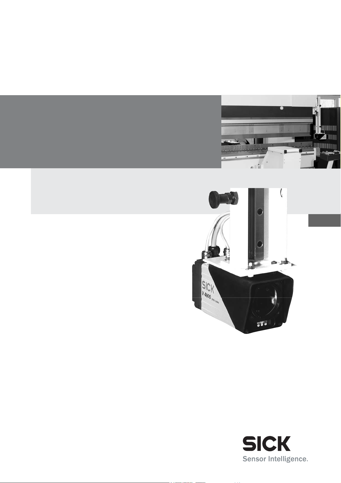
Prevent the formation of a potential difference between the load and the protective
a
WARNING
device!
If you connect loads that are not reverse-polarity protected to the OSSDs or the safety
outputs, you must connect the 0 V connections of these loads and those of the
corresponding protective device individually and directly to the same 0 V terminal strip.
This is the only way to ensure that, in the event of a defect, there can be no potential
difference between the 0 V connections of the loads and those of the corresponding
protective device.
OSSD1
Safety output 1
OSSD2
Safety output 2
OSSD1
Safety output 1
OSSD2
Safety output 2
Note
Technical specifications
Safety-related parameters according to EN ISO 13849, EN 62061, IEC 61508:
V4000 PB: General system data
Type Type 4 (IEC 61496)
Safety Integrity Level2) SIL3 (IEC 61508),
SILCL3 (EN 62061)
Category Category 4 (EN ISO 13849)
Category 4 (EN 954
3)
)
Performance Level2) PL e (EN ISO 13849)
PFHd (mean probability of a dangerous failure
1.52×10⁻⁸
per hour)
TM (mission time) 16.6 years (EN ISO 13849)
EC declaration of conformity
You can obtain the EC declaration of conformity with the standards used at: www.sick.com
2) For detailed information on the exact design of your machine/system, please contact your local SICK
representative.
3) Only valid for the assumption of conformity until 28.12.2009. From then on it will only be permissible to use
the successor EN ISO 13849.
© SICK AG • Industrial Safety Systems • Germany • All rights reserved 8010505/TL63/2009-11-27
Page 5

Insert
V4000 PB
Update
Checklist for the manufacturer
L
Checklist for the manufacturer/installer for the installation of electro-
sensitive protective equipment (ESPE)
Details about the points listed below must be present at least during initial commissioning — they are, however,
dependent on the respective application, the specifications of which are to be controlled by the manufacturer/installer.
This checklist should be retained and kept with the machine documentation to serve as reference during recurring
tests.
1. Have the safety rules and regulations been observed in compliance with the directives/standards applicable to
the machine?
2. Are the applied directives and standards listed in the declaration of conformity? Yes
3. Does the protective device fulfil the required PL/SILCL and PFHd according to EN ISO 138491/EN 62061 and
the type according to EN 614961?
4. Is the access to the hazardous area/hazardous point only possible through the protective field of the ESPE? Yes
5. Have appropriate measures been taken to prevent (mechanical protection) or monitor unprotected presence in
the hazardous area when protecting a hazardous area/hazardous point and have these been secured against
removal?
6. Are additional mechanical protective measures fitted and secured against manipulation which prevent reaching
under, over or around the ESPE?
7. Has the maximum stopping and/or stopping/run-down time of the machine been measured, specified and
documented (at the machine and/or in the machine documentation)?
8. Has the ESPE been mounted such that the required safety distance from the nearest hazardous point has been
achieved?
9. Are the ESPE devices correctly mounted and secured against manipulation after adjustment? Yes
10. Are the required protective measures against electric shock in effect (protection class)? Yes
11. Is the control switch for resetting the protective device (ESPE) or restarting the machine present and correctly
installed?
12. Are the outputs of the ESPE (OSSDs, ASInterface Safety at Work) integrated in compliance with the required
PL/SILCL according to EN ISO 13849/EN 62061 and does the integration comply with the circuit diagrams?
13. Has the protective function been checked in compliance with the test notes of this documentation? Yes
14. Are the given protective functions effective at every setting of the operating mode selector switch? Yes
15. Are the switching elements activated by the ESPE, e.g. contactors, valves, monitored? Yes
16. Is the ESPE effective over the entire period of the dangerous state? Yes
17. Once initiated, will a dangerous state be stopped when switching the ESPE on or off and when changing the
operating mode, or when switching to another protective device?
18. Has an information label for the daily check been attached so that it is easily visible for the operator? Yes
19. Have you made sure that the protective device itself when mounted is not a source of danger during machine
operation (for example, catching between the device and parts of the machine)?
This checklist does not replace the initial commissioning, nor the regular inspection by qualified safety personnel.
Yes
Yes
Yes
Yes
Yes
Yes
Yes
Yes
Yes
Yes
No
No
No
No
No
No
No
No
No
No
No
No
No
No
No
No
No
No
No
8010505/TL63/2009-11-27 © SICK AG • Industrial Safety Systems • Germany • All rights reserved
Page 6

Insert
V4000 PB
Update
© SICK AG • Industrial Safety Systems • Germany • All rights reserved 8010505/TL63/2009-11-27
Page 7

Operating instructions
V4000 PB
Contents
Contents
1 About this document ......................................................................................................6
1.1 Function of this document....................................................................................
1.2 Target groups ........................................................................................................
1.3 Scope .....................................................................................................................
1.4 Depth of information.............................................................................................
1.5 Abbreviations.........................................................................................................
1.6 Symbols used ........................................................................................................
6
6
6
6
7
8
2 On safety..........................................................................................................................
2.1 Specialist personnel..............................................................................................
2.2 Applications of the system ...................................................................................
2.3 Correct use of the system..................................................................................
2.4 General protective notes and protective measures.........................................
2.5 Safety in operation.............................................................................................
2.6 Environmental protection ..................................................................................
2.6.1 Disposal ............................................................................................
3 Product description .....................................................................................................
3.1 Special features .................................................................................................
3.2 Safety concept....................................................................................................
3.2.1 Protection principle of the V4000 PB .............................................
3.2.2 Protective volume during the operating cycle ................................
3.2.3 Intrusion of the protective volume during the operating cycle......
3.3 Range of use ......................................................................................................
3.4 Structure of the device ......................................................................................
3.4.1 Sender and receiver.........................................................................
3.4.2 Displays at the sender and receiver ...............................................
3.4.3 Interfaces at the receiver.................................................................
3.4.4 PBI (press brake interface)..............................................................
3.4.5 CDS (Configuration & Diagnostics Software)..................................
3.4.6 External operating elements ...........................................................
3.5 Possible system configurations.........................................................................
3.5.1 Source of the operator signals ........................................................
3.5.2 Baud rate communication interface ...............................................
3.5.3 Application name .............................................................................
3.5.4 Repetition interval of power-up cycle..............................................
3.5.5 Mounting of receiver........................................................................
3.5.6 Speed-dependent muting................................................................
3.5.7 Position-sensing system ..................................................................
3.5.8 External device monitoring (EDM)...................................................
3.5.9 Default value for braking distance..................................................
3.5.10 Travel for determining the braking distance ..................................
3.5.11 Braking offset ...................................................................................
3.5.12 Target speed v
3.5.13 Monitoring of the slow closing speed v
point..................................................................................................
3.5.14 Maximum closing speed and maximum overall machine
overrun..............................................................................................
3.5.15 Travel for determining the overall machine overrun......................
3.5.16 Standstill time for determining the top dead centre......................
3.5.17 Start delay for closing movement ..................................................
for determining the braking distance ............... 36
slow
from the pinch
crawl
9
9
9
10
10
11
16
16
17
17
18
18
20
21
22
23
23
24
26
28
29
31
31
33
33
33
33
34
34
34
35
35
36
36
37
37
38
38
39
8010505/TL63/2009-11-27 © SICK AG • Industrial Safety Systems • Germany • All rights reserved 3
Page 8

Operating instructions
V4000 PB
Contents
3.5.18 Time for standstill detection ............................................................ 39
3.5.19 Settling times for inputs ...................................................................
3.5.20 Discrepancy times for inputs ...........................................................
3.5.21 Start signal at reduced protective volume ......................................
3.5.22 Minimum state time for standard outputs......................................
3.5.23 Minimum switch-off time for safety-relevant outputs.....................
3.5.24 Bypass...............................................................................................
3.6 Protective operation ...........................................................................................
3.6.1 Power-up cycle ..................................................................................
3.6.2 Teach-in.............................................................................................
3.6.3 Protective volume modes in protective operation..........................
3.7 System sequences in protective operation.......................................................
3.7.1 Power-up cycle in standard mode....................................................
3.7.2 Teach-in.............................................................................................
3.7.3 Operating cycle in standard mode...................................................
3.7.4 Operating cycle in box mode............................................................
3.7.5 Operating cycle in back-stop mode .................................................
3.8 Alignment mode..................................................................................................
39
40
40
41
41
41
42
42
43
43
46
47
51
53
55
57
59
4 Mounting.......................................................................................................................
4.1 Steps for mounting .............................................................................................
4.1.1 Mounting the sender or receiver using SICK mounting kit 1.........
4.1.2 Mounting the sender or receiver using SICK mounting kit 2.........
4.1.3 Sticker: Information for daily inspection .........................................
5 Electrical installation...................................................................................................
5.1 Connecting the receiver ....................................................................................
5.2 Connecting the sender.......................................................................................
5.3 Making up the connections for receiver and sender.......................................
5.4 Connecting the PBI............................................................................................
5.5 External device monitoring (EDM) .....................................................................
5.6 Bypass.................................................................................................................
5.7 Configuration connection (serial interface).......................................................
6 Configuration................................................................................................................
6.1 Delivery state ......................................................................................................
6.2 Configuration preparations ................................................................................
7 Commissioning.............................................................................................................
7.1 Test notes ...........................................................................................................
7.2 Aligning sender and receiver .............................................................................
7.2.1 Initial alignment ................................................................................
7.2.2 Alignment following a tooling change..............................................
7.3 Function check ...................................................................................................
7.4 Regular checks of the protective device by specialist personnel...................
7.5 Daily checks of the protective device by authorised commissioned
persons ...............................................................................................................
60
60
60
61
62
63
63
66
67
67
69
70
71
72
72
73
74
74
74
74
81
83
86
86
8 Operation ......................................................................................................................
8.1 Switching the machine on..................................................................................
8.2 Selecting protective volume mode ....................................................................
8.3 Resetting .............................................................................................................
8.4 Carrying out a power-up cycle............................................................................
8.5 Carrying out teach-in ..........................................................................................
8.6 Bending in standard mode.................................................................................
88
88
89
89
89
91
92
4 © SICK AG • Industrial Safety Systems • Germany • All rights reserved 8010505/TL63/2009-11-27
Page 9

Operating instructions
V4000 PB
Contents
8.7 Bending in box mode ........................................................................................ 92
8.8 Bending in back-stop mode..............................................................................
8.9 Changing the sheet thickness...........................................................................
8.10 Tool changing .....................................................................................................
8.11 Care and maintenance ......................................................................................
92
92
93
93
9 Diagnostics...................................................................................................................
9.1 Response to errors and malfunctions...............................................................
9.2 Error displays of the LEDs..................................................................................
9.3 Error displays of the 7-segment display............................................................
9.4 Extended diagnostics via CDS...........................................................................
9.5 SICK support.......................................................................................................
10 Technical data..............................................................................................................
10.1 Device data sheet ..............................................................................................
10.1.1 V4000 PB technical data.................................................................
10.1.2 Technical data for PBI (press brake interface).............................
10.1.3 Incremental encoder technical data.............................................
10.2 Dimensional drawings .....................................................................................
10.2.1 Sender and receiver.......................................................................
10.2.2 SICK mounting kit 1 .......................................................................
11 Ordering information .................................................................................................
11.1 Scope of delivery..............................................................................................
11.2 Available systems.............................................................................................
11.3 Accessories.......................................................................................................
12 Glossary ......................................................................................................................
13 Annex .......................................................................................................................
13.1 Detailed system sequences in protective operation......................................
13.1.1 Power-up cycle................................................................................
13.1.2 Teach-in ..........................................................................................
13.1.3 Standard mode ..............................................................................
13.1.4 Box or back-stop mode with interruption of the protective
volume ............................................................................................
13.2 Declaration of Conformity................................................................................
13.3 Manufacturer’s checklist.................................................................................
13.4 List of tables.....................................................................................................
13.5 List of illustrations............................................................................................
13.6 Index .................................................................................................................
94
94
94
95
97
98
99
99
99
105
106
107
107
108
109
109
109
109
111
114
114
114
116
118
120
122
124
125
126
128
8010505/TL63/2009-11-27 © SICK AG • Industrial Safety Systems • Germany • All rights reserved 5
Page 10

Chapter 1 Operating instructions
V4000 PB
About this document
1 About this document
Read this chapter carefully before working with the operating instructions and the
V4000 Press Brake system.
For "V4000 Press Brake system" we shall use the abbreviation "V4000 PB" from now on.
1.1 Function of this document
These operating instructions are intended for the technical personnel of the machine
manufacturer or the machine operator in regards to safe mounting, electrical installation,
configuration, commissioning, operation and diagnostics of the V4000 PB sensor.
These operating instructions do not provide instructions for operating machines on which
the V4000 PB is, or will be, integrated. Information of this kind will be found in the
operating instructions for the machine.
1.2 Target groups
These operating instructions are intended for manufacturers, operators and the users of
press brakes which are to be protected by a V4000 PB. It also addresses people who
integrate the V4000 PB into a machine, initialise its use, or who check the unit.
Note
1.3 Scope
These operating instructions apply for the V4000 PB with the following type label entry in
the Operating Instructions field: 8 010 501. This document is part of SICK part number 8
010 501 (V4000 Press Brake sensor system in all available languages).
You will require a CDS (Configuration & Diagnostic Software) version 3.0 or greater for the
configuration and diagnostics of this system. To determine the software version, select the
Module info item from the ? menu in the menu bar.
1.4 Depth of information
These operating instructions contain information on the V4000 PB regarding the following
subjects:
Mounting
Electrical installation
Configuration and commissioning
Operation, care and maintenance
Planning and using protective devices such as the V4000 PB sensor also require specific
technical skills which are not detailed in these operating instructions.
When operating the V4000 PB sensor, the national, local and statutory rules and
regulations must be observed.
General information on health and safety using opto-electronic protective devices is
contained in the brochure "Safe Machines with Opto-Electronic Protective Devices".
Error diagnostics and remedying
Technical data and order numbers
Conformity and approval
6 © SICK AG • Industrial Safety Systems • Germany • All rights reserved 8010505/TL63/2009-11-27
Page 11

Operating instructions Chapter 1
V4000 PB
About this document
Note
ANSI
BWS
CDS
EDM
ESPE
HMI
LD
LD LED
MP
NC
OMO
ORT
OSSD
PBDC
PBI
PTDC
PP
SP
SPLC
V4000 PB
We also refer you to the SICK homepage on the Internet at
http://www.sick.com
Here you will find:
These operating instructions in different languages for viewing and printing
The EC Declaration of Conformity
1.5 Abbreviations
American National Standards Institute
Electro-sensitive protective equipment (ESPE) (e. g. V4000 PB)
SICK Configuration & Diagnostic Software = software for configuring and diagnosing the
V4000 PB system
External device monitoring
Electro-sensitive protective equipment
Human machine interface
Laser diode
Light-emitting diode
Mute point
Numerical control
Overall machine overrun
Overall response time
Output signal switching device = signal output of the protective device to the controller
used for switching off the movement which is the source of danger
Programmed bottom dead centre
Press brake interface
Programmed top dead centre
Pinch point
to v
Switch-over point (from v
p
Safety programmable logic control
V4000 Press Brake (sensor system)
slow
)
8010505/TL63/2009-11-27 © SICK AG • Industrial Safety Systems • Germany • All rights reserved 7
Page 12

Chapter 1 Operating instructions
V4000 PB
About this document
1.6 Symbols used
Recommendation
Note
;, , ;O(
O Yellow, Ö Yellow,
o Yellow
,
> Action …
a
WARNING
Recommendations are designed to provide some assistance for your decision-making
process regarding application of a certain function or technical measure.
Notes provide special information about the device.
Display indicators show the status of the 7-segment display of the receiver:
7 Constant display of the letter F
Flashing display of the letter F
7O) Alternating display of F and 2
LED symbols describe the state of an LED:
O The LED is illuminated constantly.
Ö The LED is flashing.
o The LED is off.
ON or OFF state:
ON
OFF
Instructions for taking action are shown by an arrow. Read carefully and follow the
instructions for action.
Warning!
A warning indicates concrete or potential dangers. They save you from harm.
Read warnings carefully and abide by them!
n
s r
Software notes show the location in the CDS (Configuration & Diagnostic Software) where
you can make the appropriate settings and adjustments. Go to the View menu, Dialogue
windows of the CDS and activate the item tabs to view the named dialogue boxes as
required. Otherwise use the software wizard to make the desired settings.
Sender and receiver
In drawings and diagrams, the s symbol denotes the sender and the symbol r the
receiver.
The term "dangerous state"
In the drawings in these operating instructions, the dangerous state (standard term) of the
machine is always represented as a movement of a machine part. In practical operation
there may be a number of different dangerous states:
Machine movements
Electrical conductors
Visible or invisible radiation
A combination of several risks and hazards
Representation of the signals for teach-in, alignment mode and selection of protective
volume mode
These operating instructions also describe the V4000 PB input and output signals. As a
way of uniquely representing the signals for teach-in, alignment mode and selection of
protective volume mode (input signals), tactile switching amplifiers (buttons, switches) are
used. The signals can be generated at the inputs of the V4000 PB by, for example, foot
switches, alignment buttons, teach-in buttons, selector switches and key-operated
switches or by the corresponding switching elements on the HMI of the press controller.
8 © SICK AG • Industrial Safety Systems • Germany • All rights reserved 8010505/TL63/2009-11-27
Page 13

Operating instructions Chapter 2
V4000 PB
On safety
2 On safety
This chapter deals with your own safety and the safety of the operators.
> Read this chapter carefully before working with the V4000 PB or with the machine
protected by the V4000 PB.
2.1 Specialist personnel
The V4000 PB must be mounted, connected, commissioned and serviced only by
specialist personnel. Specialist personnel are defined as persons who
due to their technical training and experience possess sufficient knowledge in the field
of safety equipment for making press brakes safe
and
who have been instructed by the responsible machine operator in the operation of the
machine and the current valid safety guidelines
and
have sufficient familiarity with the relevant national industrial safety regulations, work
safety regulations, directives and the generally recognised code of practice of the
industry (for example, DIN standards, VDE specifications, technical codes of other EC
member states) that they can judge whether the press brake is safe from the
occupational safety point of view
and
have access to and have read these operating instructions.
As a rule these will be specialist personnel, the manufacturer of the ESPE or even such
persons who have been given the corresponding training by the ESPE manufacturer, who
are mainly concerned with inspecting and testing ESPEs and have been commissioned by
the ESPE operator in this regard.
2.2 Applications of the system
The V4000 PB is an ESPE (electro-sensitive protective equipment) device designed to
protect the area beneath the die of press brakes at high closing speeds. As soon as an
object enters the protective volume beneath the die, the ESPE issues the signal to the
press controller to stop the fast closing movement and this system must then stop the
closing movement.
The V4000 PB system consists of a sender and a receiver which are mounted on the press
crosshead. The protective volume between the sender and the receiver moves with the
press crosshead and thus ensures that the safeguarded area stays beneath the die.
The system is a Type 4 ESPE as defined by to IEC 61 496-1 and 2 and is therefore allowed
for use with controls of safety category 4 in compliance with EN 954-1. It may be used in
safety applications up to SIL 3 in accordance with IEC 61 508.
8010505/TL63/2009-11-27 © SICK AG • Industrial Safety Systems • Germany • All rights reserved 9
Page 14
Chapter 2 Operating instructions
V4000 PB
On safety
Use of the V4000 PB in the open air or explosion hazard areas is not permitted. The
V4000 PB can only be used in normal industrial environments.
Do not use the V4000 PB as a separating protective measure!
a
WARNING
An opto-electronic protective device provides indirect protection, e.g., by switching off the
power at the source of the hazard. It cannot provide protection neither from parts thrown
out, nor from emitted radiation. Transparent objects are not detected.
Depending on its applications, mechanical protective devices may be needed in addition to
the V4000 PB.
2.3 Correct use of the system
The V4000 PB system is intended to be used solely at a fixed location on press brakes and
may only be used as defined by Section
only by specialist personnel and only on the machine where it has been mounted and
initially commissioned by specialist personnel in accordance with these operating
instructions.
SICK AG accepts no claims for liability if the equipment is used in any other way or if
modifications are made to the device, even in the context of mounting and installation.
2.2 "Applications of the system". It must be used
a
WARNING
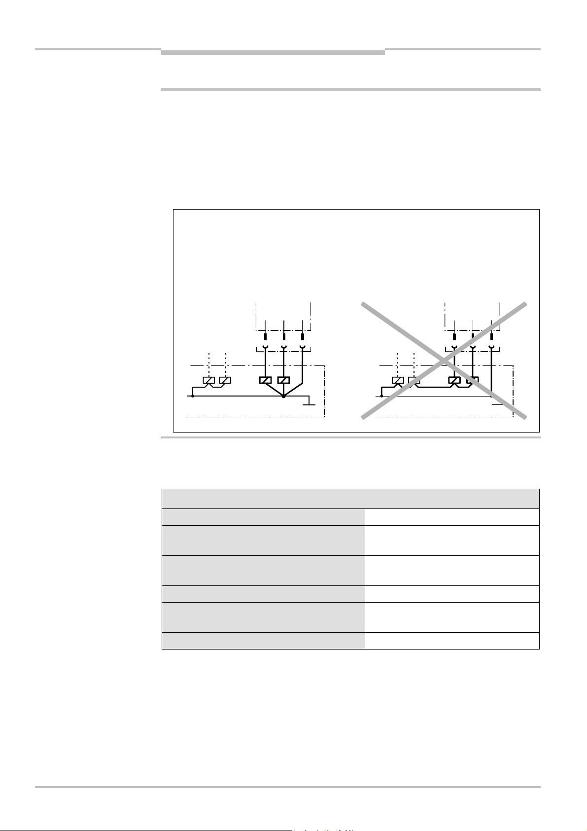
Fig. 1: Warning regarding
laser class 1M
2.4 General protective notes and protective measures
Protective notes
Please observe the following protective notes in order to ensure the correct and safe use
of the V4000 PB.
Warnings on the V4000 PB must be observed without fail.
The V4000 PB meets the requirements of laser protection class 1 M. Do not look into
the laser beam neither with the naked eye nor using optical equipment (such as
binoculars).
LASER RADIATION
DO NOT STARE INTO THE BEAM OR VIEW
DIRECTLY WITH OPTICAL INSTRUMENTS
CLASS 1M LASER PRODUCT
ACCORDING TO IEC 60825-1:2001
Max. output: < 5mW
Puls duration: < 2ms
Wavelength: 620 TO 650 nm
Complies with 21 CFR 1040.10 and 1040.11 except
for deviations pursuant to laser notice No. 50, July 2001
This device meets the norms: CDRH 21 CFR 1040.10, 1040.11 as well as DIN EN 60
825:2001. There the following note is required:”Caution – use of controls or
adjustments or performance of procedures other than those specified herein may result
in hazardous radiation exposure!”
The V4000 PB components must not be opened for maintenance work. Defective
devices have to be sent back to the manufactorer.
10 © SICK AG • Industrial Safety Systems • Germany • All rights reserved 8010505/TL63/2009-11-27
Page 15

Operating instructions Chapter 2
V4000 PB
On safety
The national/international rules and regulations apply to the installation, commissioning
and periodic technical inspections of the V4000 PB, in particular:
– Machinery Directive 98/37/EC
– Provision and use of Work Equipment Directive 89/655/EEC
– The work safety regulations/safety rules
– Relevant national health and safety regulations
Manufacturers and operators of the machine on which the V4000 PB is used are
responsible for obtaining and observing all applicable safety regulations and rules.
The notices, in particular the test regulations (see Chapter
operating instructions (e.g. on use, mounting, installation or integration into the existing
machine controller) must be observed.
The tests must be carried out by specialist personnel or specially qualified and
authorised personnel and must be recorded and documented to ensure that the tests
can be reconstructed and retraced at any time.
The operating instructions must be made available to the operator of the machine where
the V4000 PB is fitted. The machine operator is to be instructed in the use of the device
by specialist personnel and must be instructed to read the operating instructions of the
V4000 PB and of the machine.
7 "Commissioning") of these
a
WARNING
2.5 Safety in operation
Dangers which the V4000 PB does not protect against!
The different ways in which the press brake can be used in manufacturing means that
indirect dangers may arise.
Please observe and comply with the following points in order to protect yourself against
dangers during machine operation.
The V4000 PB safeguards the hazardous point beneath the die at high closing speeds
(over 10 mm/s) or irrespective of the speed up to a gap of 6 mm. The maximum height of
the protective volume up to the lower edge of the die is 26 mm.
Maximum protection is provided in standard protective volume mode.
In the case of box-bending or back-stop operation, use of a restricted protective volume is
possible. With this kind of work, the reduced dimensions of the protective volume means
that only limited protection against getting caught or crushed is possible.
If parts of the body are brought into the hazardous point within a box, they will only be
detected behind the tolerance zone around the pressure axis. There is a danger of injury
by being caught or crushed.
For a time interval of 100–150 ms (just before the gap height of 6 mm is reached) there is
the possibility of an object which is moving into the space between the die and the
workpiece being crushed.
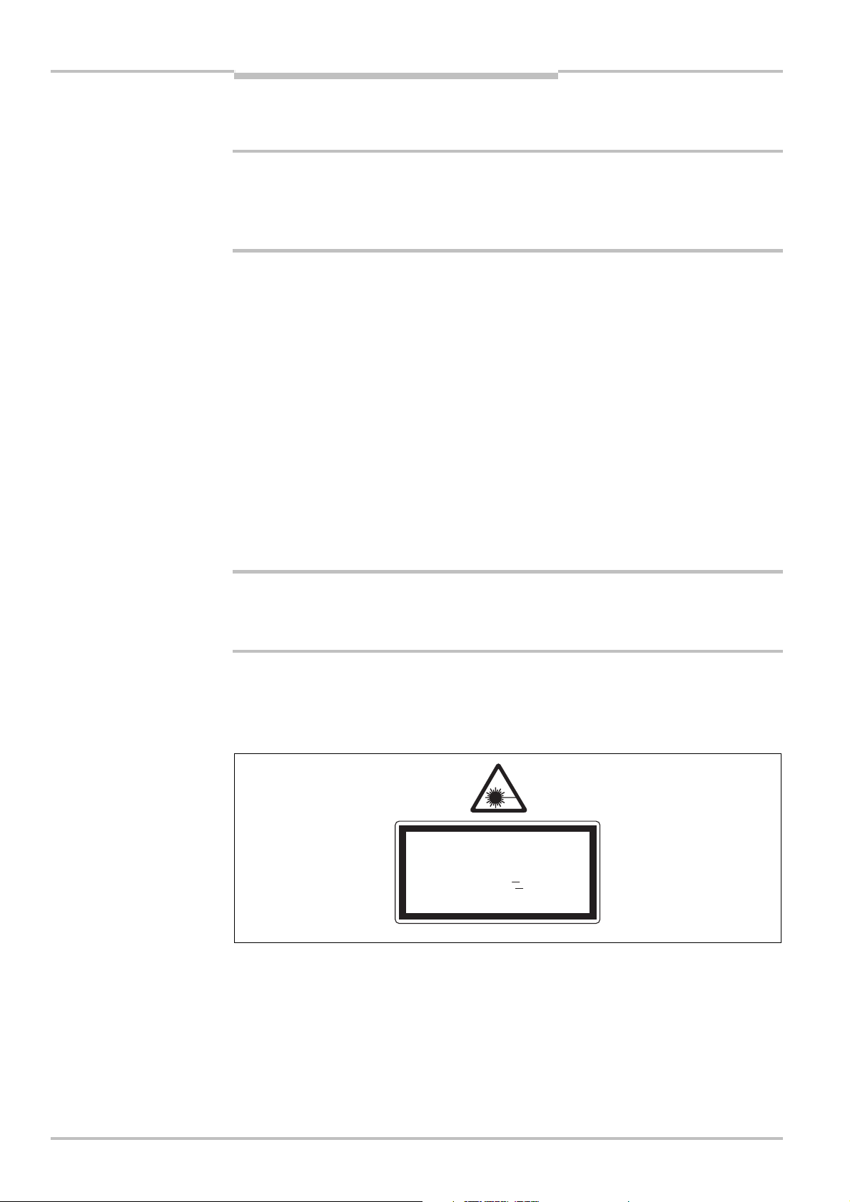
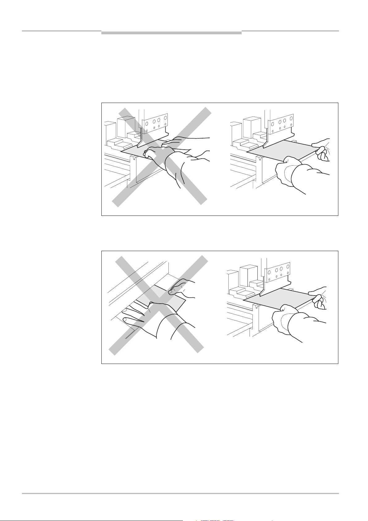
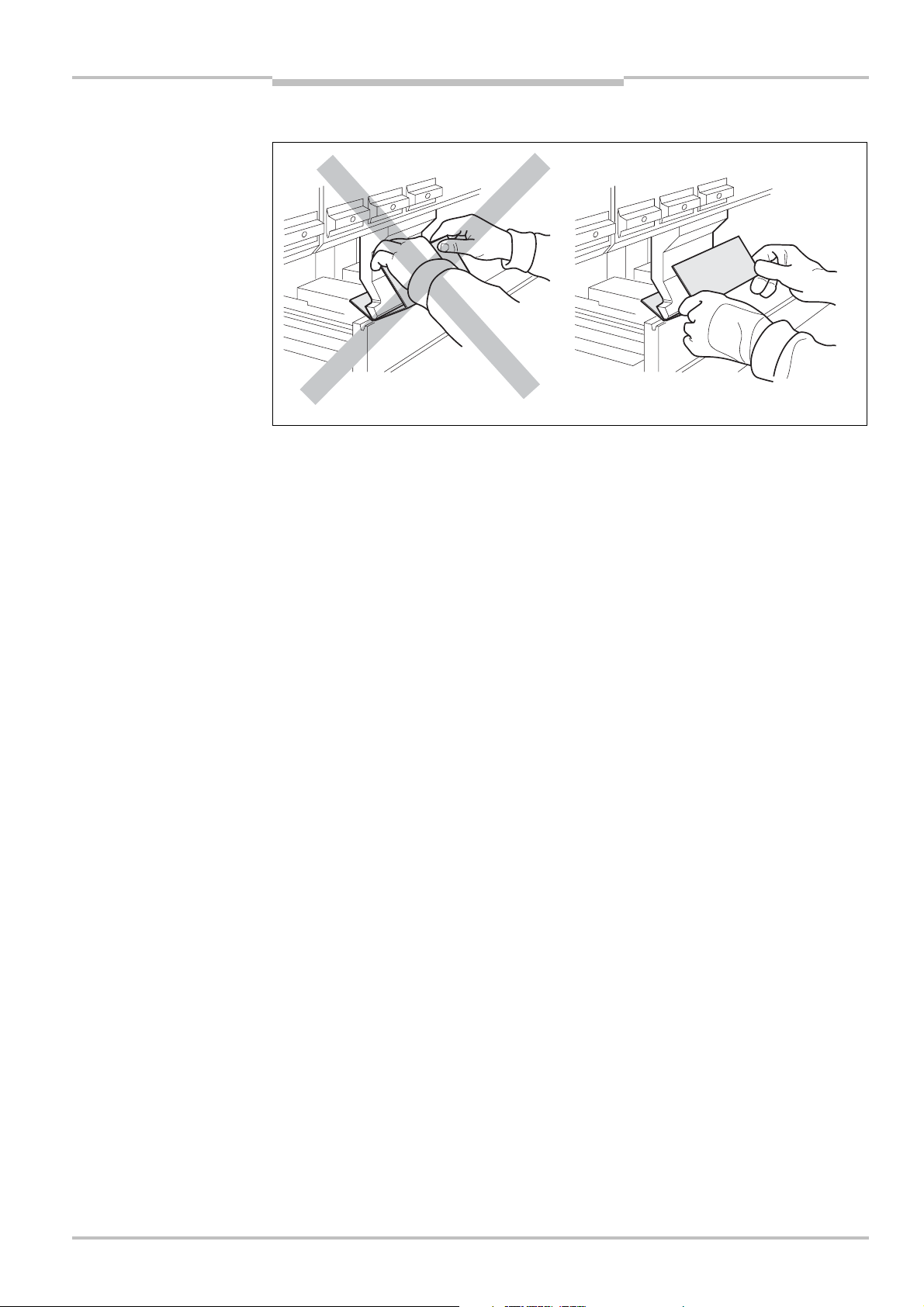
Correct handling of the workpiece
By handling the sheet properly you can avoid your hands or fingers being caught or
crushed.
8010505/TL63/2009-11-27 © SICK AG • Industrial Safety Systems • Germany • All rights reserved 11
Page 16
Chapter 2 Operating instructions
V4000 PB
On safety
> Use gloves to prevent:
– Injuries caused by edges, corners and burr
– Residues and rust caused by sweat from the hands getting on dies and workpieces
– Deposits on the hands
– Slipping of smooth workpieces
Fig. 2: Handling of the
workpiece 1
Fig.
3: Handling of the
workpiece 2
Note
> Hold the sheet by the left and right corners of the end facing you.
> Use both hands to hold the sheet firmly from below (thumb on top of the sheet, rest of
hand underneath)
> When holding the sheet, be sure not to spread your fingers.
Spread fingers will interrupt the protective volume of the V4000 PB. The protective
function of the V4000 PB will be triggered and the V4000 PB initiates a stop.
If the protective volume is limited (box-bending and back-stop operation) there will be an
additional risk of getting your hand caught.
12 © SICK AG • Industrial Safety Systems • Germany • All rights reserved 8010505/TL63/2009-11-27
Page 17
Operating instructions Chapter 2
V4000 PB
Fig. 4: Handling of
pre-flanged sheets
On safety
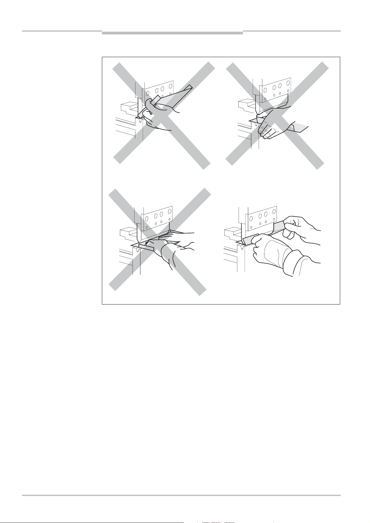
Correct handling of pre-flanged sheets
Note
If pre-flanged sheets are not handled correctly, your hands could get caught between the
sheet and the die or press crosshead.
> Hold the pre-flanged sheet by the left and right edges between the thumbs and index
fingers.
> Use both hands to hold the sheet firmly.
8010505/TL63/2009-11-27 © SICK AG • Industrial Safety Systems • Germany • All rights reserved 13
Page 18
Chapter 2 Operating instructions
V4000 PB
Fig. 5: Handling of
box-shaped workpieces
On safety
Correct handling with box-bending
Note
In box-bending and back-stop modes the protective volume is limited and a tolerance zone
around the pressure axis is hidden. If box-like workpieces are not handled correctly, your
hands could get caught between the workpiece and the die or press crosshead.
> Do not hold the upper box walls by the edges or corners on the pressure axis.
> Hold box-shaped workpieces by their back part (closest to you) outside the hazardous
point.
The V4000 PB cannot protect you against these dangers:
Crushing your hands or fingers between the workpiece and the press crosshead as a
result of handling the workpiece incorrectly during bending
Crushing your fingers between the die and the workpiece as a result of handling the
workpiece incorrectly
The risk of injury from workpieces falling when the press brake is opened
The risk of injury from large workpieces swinging upwards during bending
When bending aids are used:
Risk of injury due to the workpiece swinging up or down, or to the movement of the
bending aids
14 © SICK AG • Industrial Safety Systems • Germany • All rights reserved 8010505/TL63/2009-11-27
Page 19

Operating instructions Chapter 2
V4000 PB
Note
On safety
When automatically traversing rear stops are used:
– Crushing your hands or fingers between the rear stops and the female die during
traversing movements towards the operator
– The operator being crushed by large workpieces being pushed at him by the rear stops
Risk of injury in the rear space arising from automatically traversing stops, moving tools,
workpieces or bending aids.
Access to the rear space or standing in the rear space must be prevented by means of the
appropriate safety devices, such as a light grid.
Dangers arising from mounting of the V4000 PB
> When mounting the V4000 PB make sure that there will be no crushing or shearing
points between the moving sender and receiver and other stationary machine parts or
devices in the vicinity of the machine.
> If hazardous points cannot be avoided, they must be made safe by other protective
measures or remedied by design changes.
8010505/TL63/2009-11-27 © SICK AG • Industrial Safety Systems • Germany • All rights reserved 15
Page 20

Chapter 2 Operating instructions
V4000 PB
On safety
2.6 Environmental protection
The V4000 PB has been designed to minimise environmental impact. It uses only a
minimum of power and natural resources.
> At work, always act in an environmentally responsible manner.
2.6.1 Disposal
Disposal of unusable or irreparable devices should always occur in accordance with the
applicable country-specific waste-disposal regulations
(e.g. European Waste Code 16 02 14).
Before you can turn over the devices for environmentally-friendly recycling, you must
separate the different materials of the V4000 PB from one another.
> Separate the housing from the remaining components (especially the PCB).
> Press the front lens out of the lens holder.
Tab. 1: Overview of disposal
by component
> Send the separated components to the corresponding recycling centres (see
Component Disposal
Product
Housing
Front lens
PCBs, cables, plugs and
electrical connection pieces
Metal recycling (aluminium)
Glass recycling (used glass)
Electronics recycling
Tab. 1).
Note
a
WARNING
Packaging
Cardboard, paper
Polyethylene packaging
We would be pleased to be of assistance on the disposal of the V4000 PB. Contact your
local SICK representative.
Material separation may only be performed by specialist personnel!
Exercise care when disassembling the devices. The danger of injury is present.
Paper/cardboard recycling
Plastic recycling
16 © SICK AG • Industrial Safety Systems • Germany • All rights reserved 8010505/TL63/2009-11-27
Page 21

Operating instructions Chapter 3
V4000 PB
Product description
3 Product description
This chapter provides information on the special features and properties of the V4000 PB.
It describes the safety concept, the range of use, the structure and operating principle of
the device, configuration options and the various operating modes.
> Read this chapter before you mount, install and commission the V4000 PB.
3.1 Special features
Sender/receiver system
Response time 10 ms
Unambiguous status information via LED and 7-segment display shown directly on the
V4000 PB receiver
All inputs and outputs of the system integrated in the receiver
Simple combination of the V4000 PB system with alternative protective measures by
means of bypass inputs and outputs
No additional evaluation unit required in the control cabinet
V4000 PB system uses the existing measurement guides of the press brake for
determining speed, position and direction
Optional operation via hardware input devices or via the outputs of the press brake
controller (e.g. NC).
The SICK CDS user interface provides ease of configuration and comprehensive
expanded diagnostics of the V4000 PB system
Reliable pinch-point monitoring even when workpiece surface has irregularities or
unevenness
Automatic functions
Determination and monitoring of the pinch point
Monitoring of the relevant overall machine overrun of the press brake as a function of
speed
Monitoring of the slow closing speed (≤ 10 mm/s) from pinch point V4000 PB (can be
configured)
Dynamic adaptation of the switch-over point
Position-dependent muting (6 mm above the pinch point)
Speed-dependent muting (configurable)
Checking of the die position to detect coarse maladjustment
Detection of box wall in front and rear spaces
Protective operation
3 protective volume modes with adapted protective volume shape corresponding to
bending task
Loading of press hydraulics minimised by box and back-stop modes without emergency
stop at box wall
8010505/TL63/2009-11-27 © SICK AG • Industrial Safety Systems • Germany • All rights reserved 17
Page 22
Chapter 3 Operating instructions
6
r
/
r
V4000 PB
Product description
3.2 Safety concept
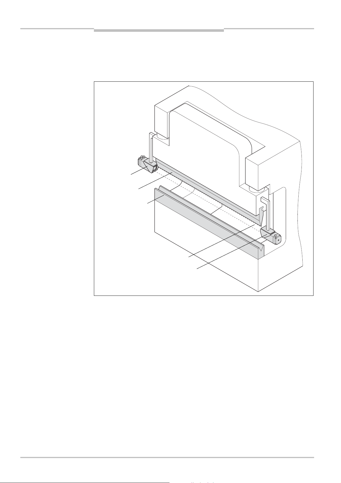
3.2.1 Protection principle of the V4000 PB
Fig.
: Press brake with
V4000 PB
Press crosshead
Receive
Die
Female die
Illumination field
protective volume
Sende
The V4000 PB consists of a sender and a receiver mounted on the press crosshead.
A light beam of light (illumination field) between sender and receiver forms a threedimensional protective field (protective volume) beneath the die tip measuring 40 mm
wide and 26 mm high. The protective volume follows the movement of the press
crosshead and in this way provides a travelling safety zone beneath the die tip.
The V4000 PB has three different kinds of protective volume (standard, box and backstop). These protective volumes differ in their dimensions and in their functions.
Should there be a partial or complete interruption of the protective volume by an object,
the output signal switching devices (OSSDs) of the ESPE which are integrated in the
receiver change over to the OFF state and generate a two-channel monitored switch-off
signal to the press controller which then must stop the closing movement of the press
crosshead with the die.
The evaluation and run concepts of the V4000 PB have been designed so that the ESPE
constantly checks its internal expected position (which depends on the operating mode,
the press crosshead position and the speed) against the actual external situation. Only
when the expected position is identical to the actual circumstances will the OSSDs remain
in the ON state. Any other result will put the OSSDs into the OFF state.
18 © SICK AG • Industrial Safety Systems • Germany • All rights reserved 8010505/TL63/2009-11-27
Page 23
Operating instructions Chapter 3
7
d
V4000 PB
Product description
The V4000 PB safeguards the hazardous point beneath the die at high closing speeds
(> 10 mm/s) and a pass-through gap height of more than 6 mm. If the gap height between
the top of the workpiece and the die tip is 6 mm or less, the ESPE switches automatically
into muting mode.
If the muting option is activated at a low closing speed (≤ 10 mm/s), the system will
automatically go into muting mode even when the slow closing speed is reached. The
speed is monitored continuously.
In the muting state, the protective volume is inactive and the OSSDs stay in the ON state.
Note
Whether muting is permitted at the slow closing speed varies from country to country. This
option is by default disabled in the configuration.
In the event of system errors (such as an error being detected when the hardware is
tested) the V4000 PB switches into lock-out state.
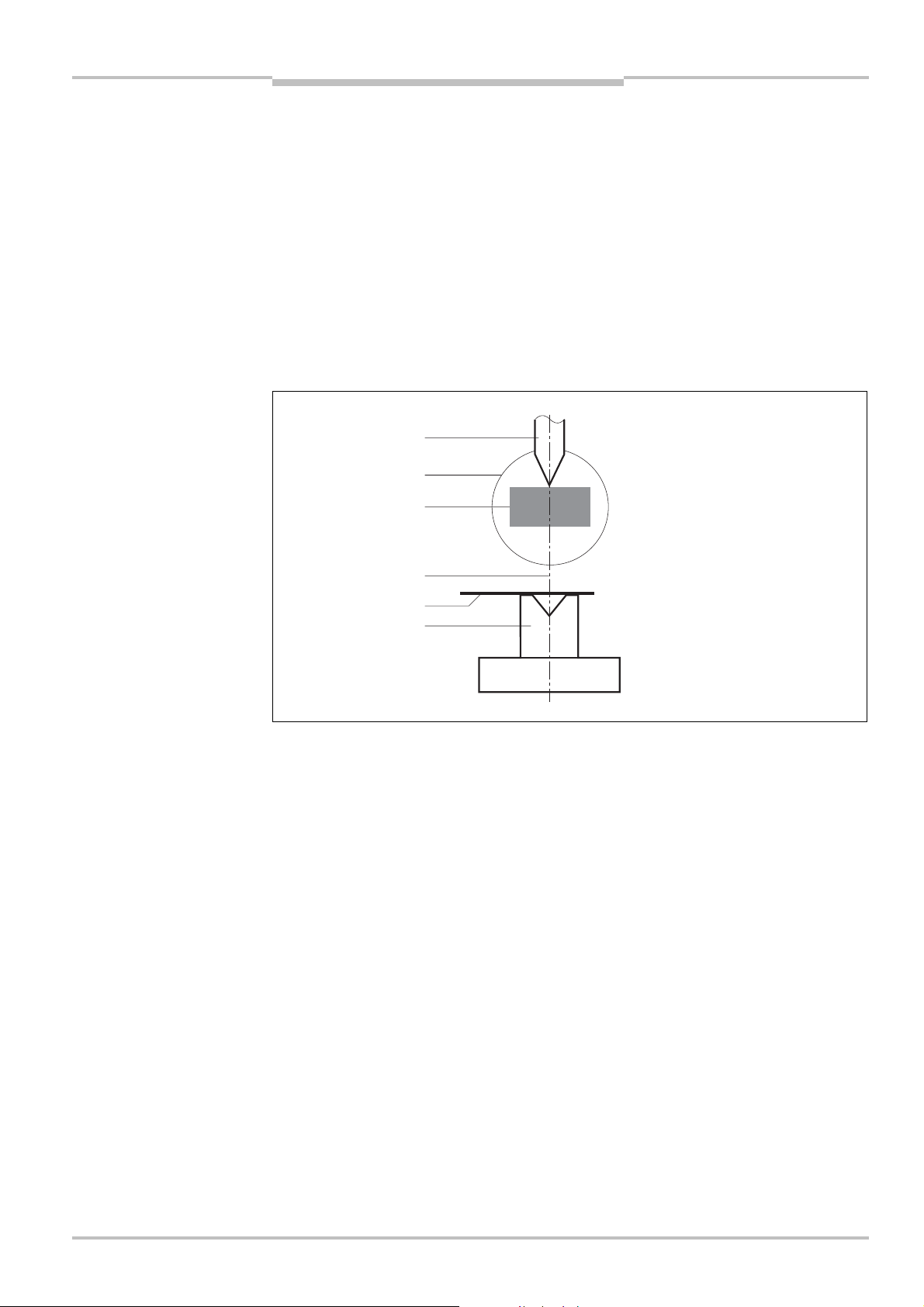
Fig.
: Definitions
Die
Illumination fiel
Protective volume
Pressure axis
Workpiece
Female die
8010505/TL63/2009-11-27 © SICK AG • Industrial Safety Systems • Germany • All rights reserved 19
Page 24
Chapter 3 Operating instructions
V4000 PB
Product description
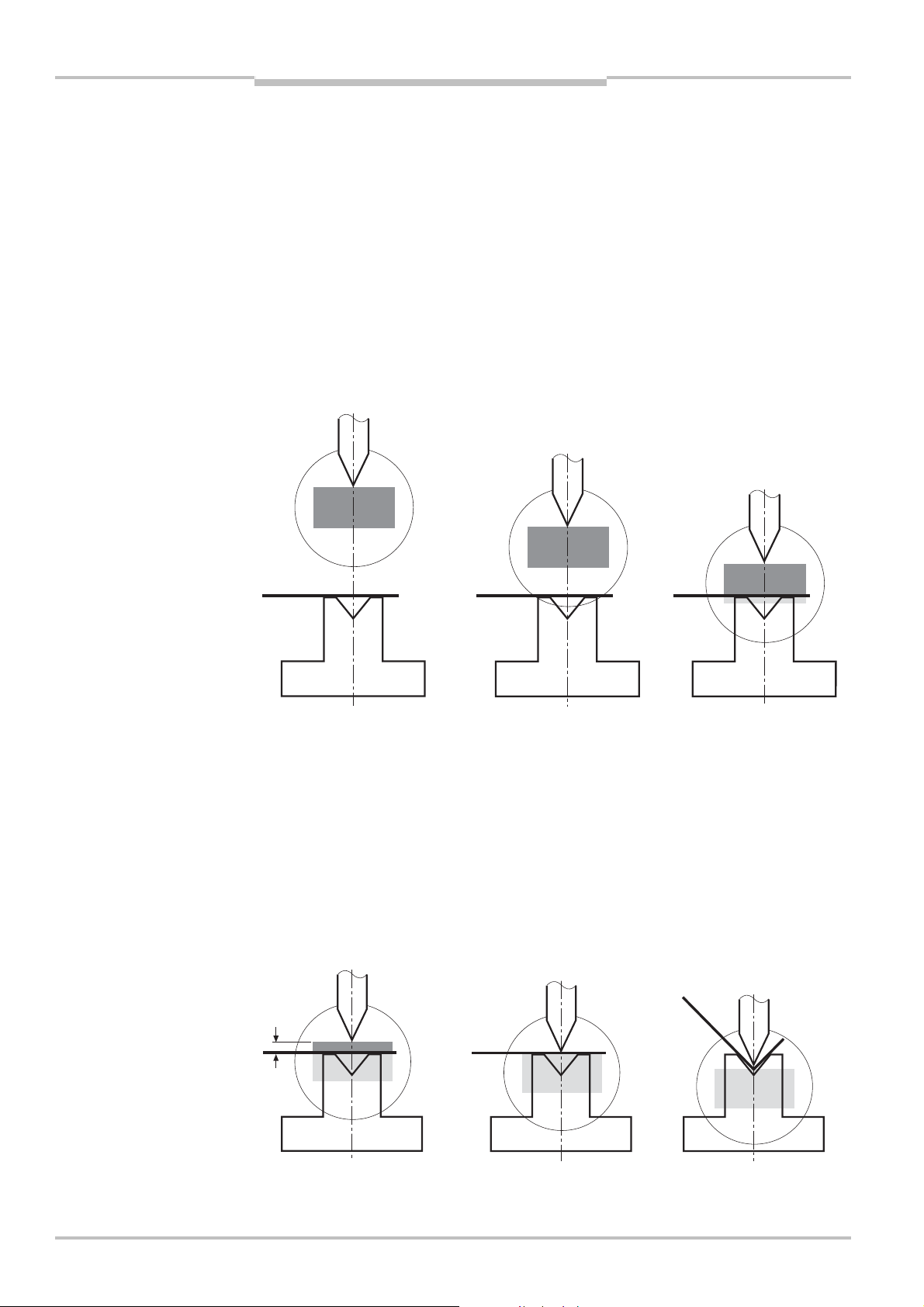
3.2.2 Protective volume during the operating cycle
This sequence shows the protective volume during one operating cycle.
Step
Protective volume
1 The die is at the
programmed top dead
centre.
The operator gives the
signal to start the
closing movement (foot
switch).
2 The die descends at
high speed
(> 10 mm/s).
The entire protective
volume is active.
3 At the switch-over point
the target speed is
requested by the
V4000 PB.
The press controller
initiates the braking
procedure.
The protective volume
stays active in the gap
opening.
Step
Protective volume
4 The calculation of the
switch-over point
includes an additional
6 mm safety gap
required to reach the
target speed (v
The protective volume
becomes inactive.
6 mm
slow
5 The die contacts the
workpiece (pinch point).
).
6 The die shapes the
workpiece. The
operating cycle ends at
the programmed bottom
dead centre. The die
goes back up.
20 © SICK AG • Industrial Safety Systems • Germany • All rights reserved 8010505/TL63/2009-11-27
Page 25
Operating instructions Chapter 3
V4000 PB
Product description
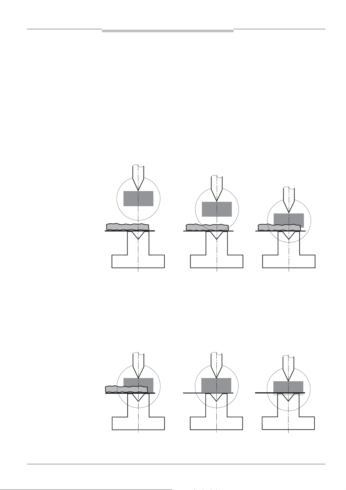
3.2.3 Intrusion of the protective volume during the operating cycle
This sequence shows how the V4000 PB responds when there is an interruption to the
protective volume.
Step
Protective volume
1 The die is at the
programmed top dead
centre.
There is a foreign object
on the workpiece or
female die.
The operator gives the
signal to start the
closing movement (foot
switch).
2 The die descends at
high speed
(> 10 mm/s).
The entire protective
volume is active.
3 Part of the protective
volume is interrupted by
the object.
The OSSDs go into the
OFF state and generate
a safe stop signal.
The press controller
must ensure the stop
procedure is
implemented.
Step
Protective volume
4 The die continues to
move in accordance
with the overall machine
overrun and stops at
least 5 mm above the
object.
5 The object is now
removed.
The protective volume is
clear again.
6 The operator gives the
signal once more to
start the closing
movement (foot switch).
The closing movement
starts and the operating
cycle resumes.
8010505/TL63/2009-11-27 © SICK AG • Industrial Safety Systems • Germany • All rights reserved 21
Page 26

Chapter 3 Operating instructions
V4000 PB
Product description
3.3 Range of use
The V4000 PB is an ESPE (electro-sensitive protective equipment) device designed to
protect the area beneath the die of press brakes at high closing speeds, it provides hand
and fingers protection.
The V4000 PB is suitable for stationary use in press brakes with a maximum distance of
7.5 m between the sender and the receiver.
The press brake must be designed to comply with the maximum stopping distance of
11 m.
This corresponds, for example, to a maximum overall machine overrun of 8.5 mm at a
maximum closing speed of 300 mm/s (see also Section
closing speed vcrawl from the pinch point").
Requirements for use of the V4000 PB
Before the V4000 PB can carry out its protective functions the following conditions must
be met:
It must be possible to influence the control of the press brake by electrical means.
The OSSDs of the V4000 PB must be incorporated into the press controller in such a way
that when the OSSDs give the switch-off signal:
– the dangerous state (high closing speed of > 10 mm/s) is stopped.
or
– the press, should the lock-out state occur, does not start up again.
The V4000 PB must be mounted and configured in such a way that it can detect objects
when they penetrate into the hazardous point.
3.5.13 "Monitoring of the slow
22 © SICK AG • Industrial Safety Systems • Germany • All rights reserved 8010505/TL63/2009-11-27
Page 27
Operating instructions Chapter 3
r
7
y
r
t
C
V4000 PB
Product description
3.4 Structure of the device
The V4000 PB comprises the following components:
Sender
Receiver with interfaces
PBI with interfaces
CDS (software for configuration and diagnostics of the V4000 PB sensor)
In addition the V4000 PB needs control signals from external operating elements.
The sections which follow describe the individual components of the device.
Fig. 8: Components
N
PBI
SPLC
Fig.
9: Sender and receiver
Incremental
encoders
3.4.1 Sender and receiver
Incremental
encoders
Operating
elements
HMI
CDS
Star
Receive
LEDs
-segment displa
Sende
LED
Sender and receiver are mounted on the press crosshead and follow the movements of
the crosshead. At start-up and every time there is a change of tooling, they need to be
precisely aligned to the length of the die used and to each other.
8010505/TL63/2009-11-27 © SICK AG • Industrial Safety Systems • Germany • All rights reserved 23
Page 28
Chapter 3 Operating instructions
w
V4000 PB
Product description
The laser diode in the sender emits light which is collected at the transmitting lens and
given parallel alignment. The beam of light, which has a constant diameter of 58 mm
(illumination field), travels along the lower side of the die to the receiver. In the receiver
the light beam is mapped at the image detector.
The evaluation electronics with all relevant inputs and outputs is built into the receiver.
Two output switching elements (OSSDs), which go into the OFF state when the sensor
function is triggered, pass on the signal for stopping the closing movement (high closing
speed > 10 mm/s).
3.4.2 Displays at the sender and receiver
Display at the sender
Fig. 10: Display at the sender
Tab.
2: Display at the sender
LED: Yello
An LED on the sender displays the status.
Display Meaning
O Yellow Power supply OK.
The sender of the V4000 PB is switched on.
24 © SICK AG • Industrial Safety Systems • Germany • All rights reserved 8010505/TL63/2009-11-27
Page 29
Operating instructions Chapter 3
3:
w
7
y
V4000 PB
Product description
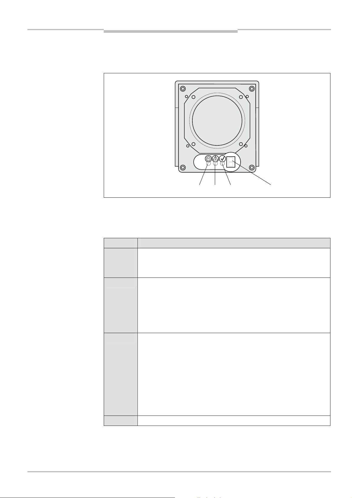
Displays at the receiver
The status of the system is displayed at the receiver by three LEDs and a
7-segment display.
Fig. 11: Displays at the
receiver
Yello
LEDs:
Red
Green
-segment displa
The LEDs tell the operator whether an input is expected and whether the OSSDs are in the
OFF or ON state.
The 7-segment display provides the operator with further information about the status of
the V4000 PB.
Tab.
the receiver display
Key to the LEDs on
Display Meaning
Ö Yellow
(10/90)
(90/10)
Operator action (input) is required (On % / Off % at 1 Hz)
– Alignment mode
– Teach-in request
O Yellow In production operation: Operator action (input) required
– In standard mode (release foot switch)
– In back-stop mode (first operation of the foot switch expected)
– In box mode (first operation of the foot switch expected)
During configuration: CDS connected and Configuration operating mode
selected
O Red System sending signals to switch off the machine
(OSSDs in the OFF state)
Additional states in which the red LED is illuminated:
– Self-test (system initialisation)
– Configuration
– Box mode
– Back-stop mode
– Lock-out state
– Alignment mode
O Green System free (OSSDs in the ON state)
8010505/TL63/2009-11-27 © SICK AG • Industrial Safety Systems • Germany • All rights reserved 25
Page 30

Chapter 3 Operating instructions
V4000 PB
Tab. 4:
Key to the 7-segment
display on the receiver
Product description
Display Meaning
6 System error. The device is defective. Replace the receiver.
M Muting state
` Switch on. This is followed by self-testing of the V4000 PB
(system initialisation).
L Standard mode
= Box mode
} Back-stop mode
Note
Other
displays
Further explanations of the 7-segment display will be found in the following sections:
Displays during system initialisation when the machine is switched on (see Section
"
Switching the machine on")
Displays within alignment mode (see Section
Error displays within lock-out state (see Section
All of the other displays are error messages, displays within alignment
mode or displays during the self-test (system initialisation).
8.1
7.2 "Aligning sender and receiver")
9.2 "Error displays of the LEDs")
3.4.3 Interfaces at the receiver
The receiver of the V4000 PB has the following interfaces:
Digital interface
Serial interfaces for configuration and diagnostics
Interface for connecting the sender
Interface for connecting the PBI
26 © SICK AG • Industrial Safety Systems • Germany • All rights reserved 8010505/TL63/2009-11-27
Page 31

Operating instructions Chapter 3
V4000 PB
Product description
Digital interface
The digital interface receives signals from the press controller or from external operating
elements and passes them on to the receiver; it also passes signals from the receiver on
to the press controller.
Tab. 5: Inputs and outputs at
the digital interface
Number
2 Actively tested semiconductor
Inputs and outputs
with safety relevance
switching outputs (OSSDs)
Function
For the switch-off signal to the press controller
which must stop the closing movement of the
press crosshead with the die
2 Inputs For the gated signal for starting the closing
movement
Number
Standard inputs and outputs Function
2 Pulsed outputs For the bypass signal
2 Inputs For the bypass signal
1 Input For external device monitoring (EDM)
1 Output For the target speed request to the press
controller
1 Input For activating alignment mode
1 Input For activating teach-in mode
3 Inputs For selecting the protective volume mode
(standard, box, back-stop) within protective
operation
1 Output For the signal to the press controller that
teach-in is being requested
Serial interface for configuration and diagnosis
The PC is connected to the receiver via the serial RS-232 interface for configuration of the
V4000 PB and for extended diagnostics with the SICK CDS Software in the event of
servicing. For a permanent connection of the PC (CDS) to the receiver an RS-422 interface
is available for extended diagnostics. A switch allows you to switch between the two
interfaces (see Section
6.1 "Delivery state").
Interface for connecting the sender
To allow control of the sender function by the receiver, the sender and the receiver are
electronically connected to the receiver via a signal line.
Interfaces for connecting the PBI
The receiver is provided with an interface for data transmission (incremental pulses of the
measurement guide) from the PBI.
8010505/TL63/2009-11-27 © SICK AG • Industrial Safety Systems • Germany • All rights reserved 27
Page 32

Chapter 3 Operating instructions
V4000 PB
Product description
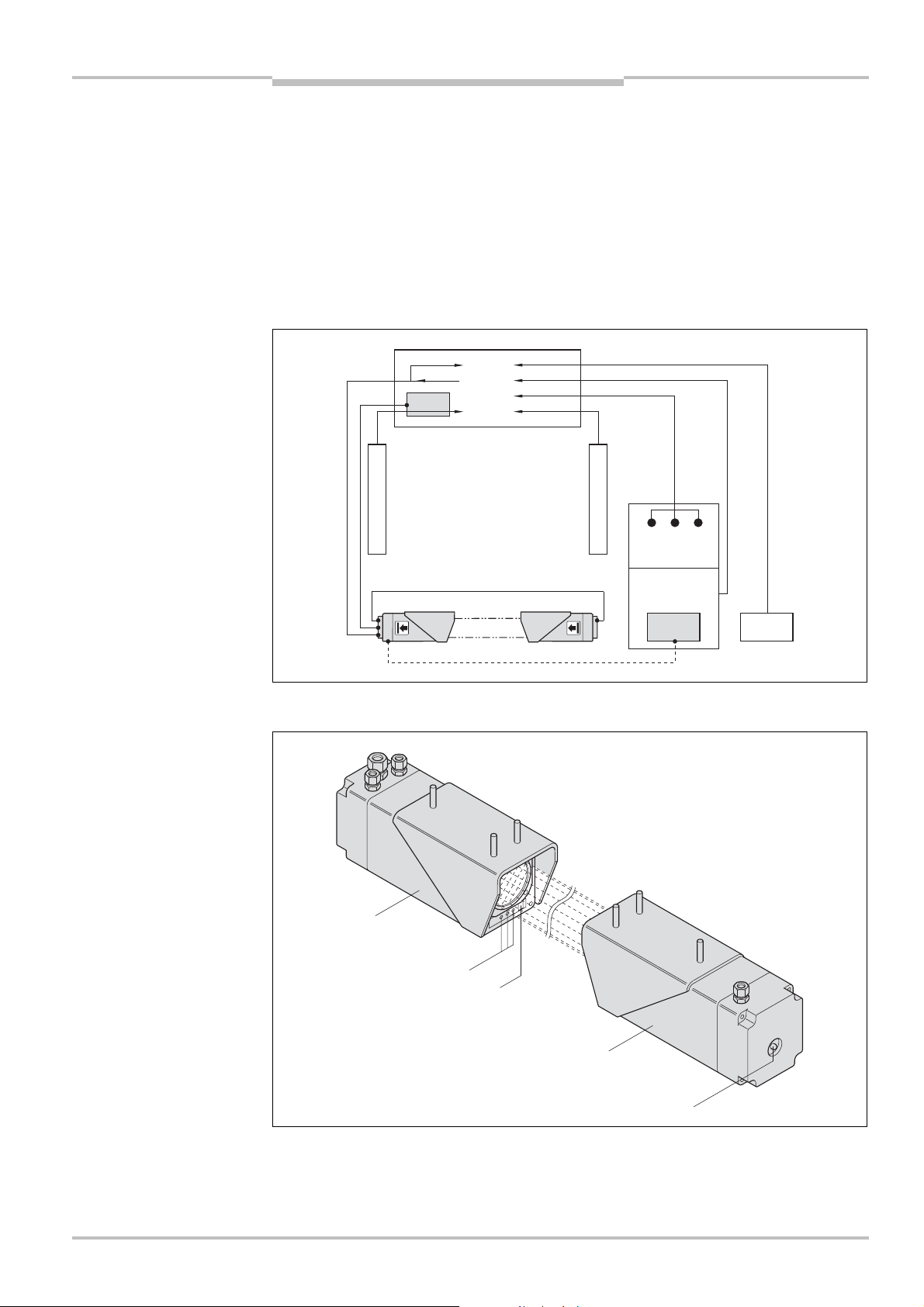
3.4.4 PBI (press brake interface)
Fig. 12: PBI (press brake
interface)
The incremental measurement guides of the press controller register the movement of the
press crosshead. The speed and direction of movement of the press crosshead and the
overall machine overrun are calculated by the V4000 PB from the signals of one
measurement guide and from other measured data (such as time).
The measurement guide is connected to the V4000 PB via the PBI in the control cabinet.
At the interface with the press controller the PBI taps onto the signals of the measurement
guide, decouples them and passes them on to the receiver.
Position detection must be checked to ensure it is working properly. The V4000 PB
monitors whether the signals (increments) from the measurement guide have a logical
order – in other words, whether they can be interpreted unambiguously as upward or
downward movement or standstill.
Example
If a start signal for the closing movement is detected by the safety-relevant inputs, it will be
assumed that the press brake is moving after a period of delay (start-up delay). If there is
no movement – in other words, the signals from the PBI cannot be unambiguously
interpreted as movement – the V4000 PB assumes that there is a fault in position
detection, switches the OSSDs into the OFF state, and goes into lock-out state.
The system will not change into the muting state unless the measurement system is
delivering correct information which agrees with the expected values.
28 © SICK AG • Industrial Safety Systems • Germany • All rights reserved 8010505/TL63/2009-11-27
Page 33

Operating instructions Chapter 3
w
V4000 PB
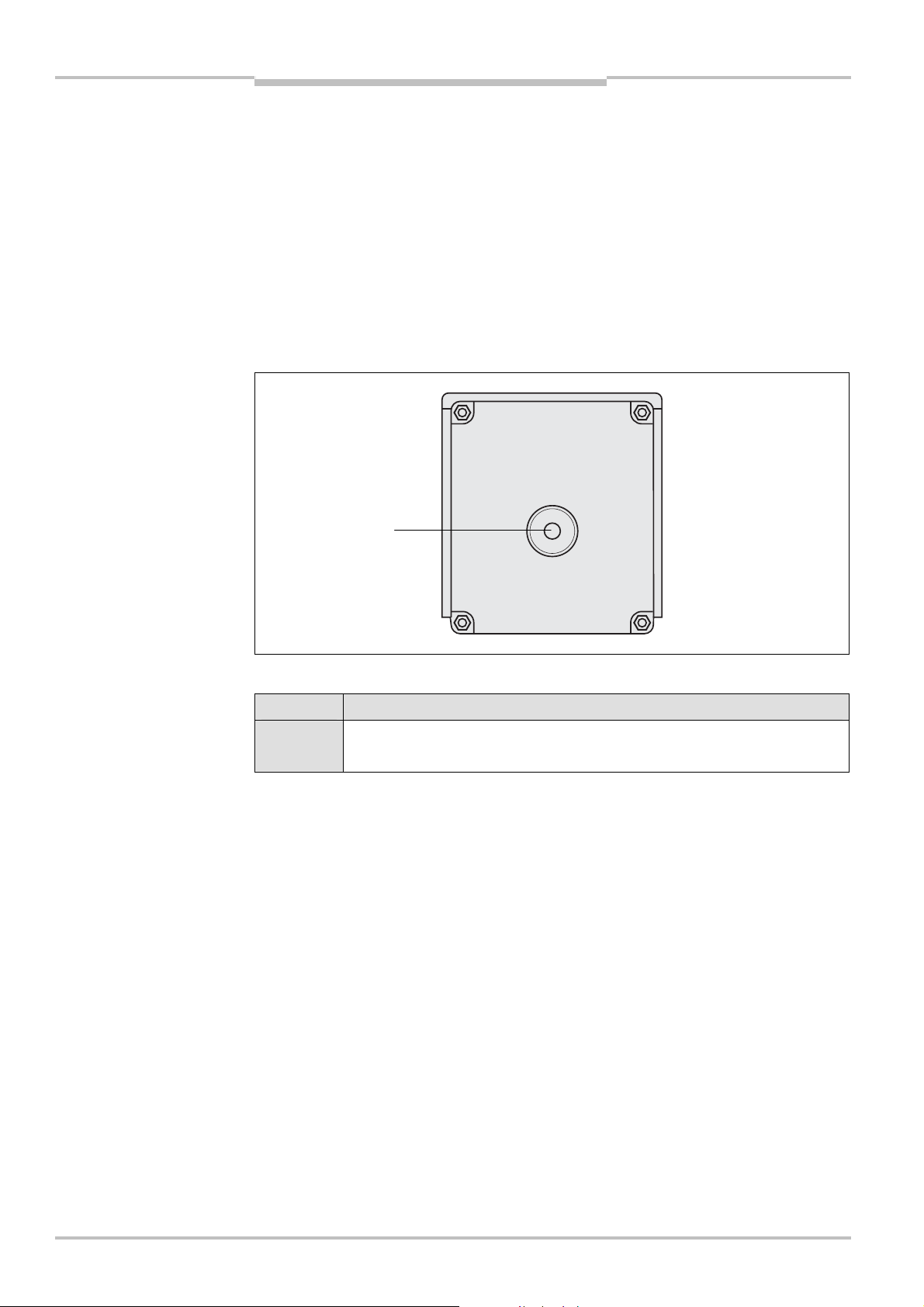
Fig. 13: Display at the PBI
Product description
Display at the PBI
LED: Yello
Tab.
6: Display at the PBI
Note
Display Meaning
O Yellow Power supply OK.
Interface at the PBI
The PBI of the V4000 PB has been designed for two-channel, incremental, linear
measurement guides with an RS- 422 interface. All signals of the measurement guide are
looped through.
3.4.5 CDS (Configuration & Diagnostics Software)
The V4000 PB is configured and diagnosed with the CDS software (Configuration &
Diagnostics Software) running on Windows 98 and later operating systems.
For more information see the Sections
3.5 "Possible device configurations" and 9.4
"Extended diagnostics via CDS".
8010505/TL63/2009-11-27 © SICK AG • Industrial Safety Systems • Germany • All rights reserved 29
Page 34

Chapter 3 Operating instructions
t
C
t
C
V4000 PB
Product description
System configuration: version A
In the case of press brakes with PC control and a Windows user interface, the CDS for
configuration or diagnostics of the V4000 PB can be integrated into the control system.
Note
Fig. 14: System configuration
with PC control
Permanent – on-line - diagnostics and operation must be implemented solely via the
RS-422 interface.
N
PBI
SPLC
Fig.
15: System configuration
without PC control
Incremental
encoders
Incremental
encoders
Operating
elements
HMI
CDS
Star
System configuration: version B
In the case of press brakes without PC control or a Windows user interface, the CDS for
configuring the V4000 PB must be connected to the receiver. A permanent connection
with the CDS is not necessary.
N
PBI
SPLC
Incremental
encoders
CDS
Incremental
encoders
Operating
elements
HMI
Star
30 © SICK AG • Industrial Safety Systems • Germany • All rights reserved 8010505/TL63/2009-11-27
Page 35

Operating instructions Chapter 3
V4000 PB
Note
Recommendation
Product description
3.4.6 External operating elements
For controlling the V4000 PB external signals are required. The V4000 PB has the
corresponding signal inputs for:
Starting the closing or opening movements of the press brake
Requesting alignment mode
Requesting or confirming teach-in
Selecting the protective volume mode (standard, box, back-stop)
Requesting bypass mode
The signals are generated either by operating elements such as buttons or selector
switches or by the outputs of the press controller (e.g. NC).
How these various possibilities are actually implemented (for example, foot switch,
alignment button, teach-in button, selector switch and key-operated switch, or
corresponding switching elements on the MMI of the press controller) falls within the area
of responsibility of the user.
All switching elements should be large and sturdy. It must be possible to operate them
reliably and simply while wearing gloves.
a
WARNING
n
3.5 Possible system configurations
This section describes the parameters and functions of the V4000 PB which can be
configured via CDS.
Check the V4000 PB after making changes!
After making any change to the configuration you must check the effectiveness of the
V4000 PB (function and configuration data).
When starting to configure the V4000 PB, you may save the configuration using an
application name with a maximum of 22 characters. You should use unique designations
with an evident relation to the concrete application name – such as "Machine name XYZ".
V4000 PB device symbol, context menu Configuration draft, Edit, Basic settings tab
8010505/TL63/2009-11-27 © SICK AG • Industrial Safety Systems • Germany • All rights reserved 31
Page 36

Chapter 3 Operating instructions
7
V4000 PB
Tab.
: Configurable
parameters and functions
Product description
Basic settings
Description in Section
Source of the operator signals 3.5.1
Baud rate of communication interface 3.5.2
Application name 3.5.3
Repetition interval of power-up cycle 3.5.4
Mounting of receiver 3.5.5
Position-sensing system 3.5.7
Increments per mm stroke
Measurement direction during closing movement
Speed-dependent muting 3.5.6
External device monitoring 3.5.8
Standstill time for determining the top dead centre 3.5.16
Start delay for closing movement 3.5.17
Time for standstill detection 3.5.18
Braking distance
Default value for braking distance 3.5.9
Travel for determining braking distance 3.5.10
Braking offset 3.5.11
Target speed v
Monitoring of the slow closing speed v
3.5.12
slow
from the pinch
crawl
3.5.13
point
Overall machine overrun
Max. overall machine overrun 3.5.14
Travel for determining overall machine overrun 3.5.15
Maximum closing speed 3.5.14
Inputs
Settling times for standard inputs
3.5.19
Settling times for safety-relevant inputs
Discrepancy time for safety-relevant inputs
3.5.20
Discrepancy time for protective volume selection
Maximum duration of 1st operation
3.5.21
(confirmation of reduced protective volume)
Start signal
Time for pause between 1st and 2nd operation
Outputs
Minimum state time for standard inputs 3.5.22
Minimum switch-off time of safety-relevant outputs 3.5.23
Bypass
Bypass 3.5.24
Discrepancy time for bypass inputs 3.5.20
32 © SICK AG • Industrial Safety Systems • Germany • All rights reserved 8010505/TL63/2009-11-27
Page 37

Operating instructions Chapter 3
V4000 PB
Note
Product description
3.5.1 Source of the operator signals
With the CDS the V4000 PB can be configured to accept operator signals (alignment,
teach-in, reset, and selection of the protective mode) either from the CDS software or from
external touch elements such as buttons or selector switches. Use of CDS to provide these
operator signals requires a dedicated permanent (on-line) communication interface
between the V4000 PB and CDS via a RS-232 port.
Another method for providing operator signals to the V4000 PB is via the HMI of the
numerical control. These signals could be collected via touch buttons connected to the NC
interface or via software buttons on the HMI console.
Signals of the operating elements of the CDS overwrite signals of the external operating
elements. There could be inconsistencies between the system state and the state of the
V4000 PB.
V4000 PB device symbol, context menu Configuration draft, Edit, Basic settings tab
n
3.5.2 Baud rate communication interface
By means of the CDS the baud rate (transmission rate) can be set at the serial interface
for configuration (between V4000 PB and connected PC). The setting will depend on how
powerful the PC is.
V4000 PB device symbol, context menu Configuration draft, Edit, Basic settings tab
n
n
n
3.5.3 Application name
When starting to configure the V4000 PB, you may save an application name with a
maximum of 22 characters.
Here you should use unique designations with an evident relation to the concrete
application name – such as "Machine name XYZ".
V4000 PB device symbol, context menu Configuration draft, Edit, Basic settings tab
3.5.4 Repetition interval of power-up cycle
The V4000 PB has an internal time monitor for certain functions. The time monitor should
ensure a regular check is made in the case of uninterrupted operation. The start times are
saved and compared with the current state. If the time for a particular function has
elapsed, a corresponding operator action will be requested.
Following an interruption to the supply voltage all times will be reset to zero.
The V4000 PB monitors the time since the last power-up cycle and requests a new powerup cycle if the configured value (≤ 24 h) is exceeded.
V4000 PB device symbol, context menu Configuration draft, Edit, Basic settings tab
8010505/TL63/2009-11-27 © SICK AG • Industrial Safety Systems • Germany • All rights reserved 33
Page 38

Chapter 3 Operating instructions
V4000 PB
Product description
3.5.5 Mounting of receiver
In back-stop mode, the active protective volume segment as seen from the operator side is
behind the pressure axis.
In order to place the active protective volume correctly, it is necessary to specify during
configuration on which side of the press brake (as seen from the operator side) the
receiver is mounted.
V4000 PB device symbol, context menu Configuration draft, Edit, Basic settings tab
n
3.5.6 Speed-dependent muting
Any one of the following conditions will result in automatic muting of the V4000 PB
(inactivation of the protective volume):
Gap size ≤ 6 mm above the taught-in pinch point
Upward movement
Note
In addition a closing movement at a low closing speed v
the system to go automatically into muting mode provided this option has been enabled
during configuration.
The closing speed is continually monitored. If the slow closing speed v
the muting state, muting will be deactivated and the protective volume activated.
With automatic muting at the slow closing speed v
close at slow closing speed despite an interruption of the protective volume.
If slow closing speed v
interrupted, the press will be stopped. After this the press brake can be closed at slow
closing speed via the press controller and a new start signal.
If slow closing speed has already been reached when the protective volume is interrupted,
a new start signal will not be needed.
If a slow closing speed (≤ 10 mm/s) is permitted by the applicable regulations as the sole
protective measure, the option may be activated by the machine setter. In ANSI standard
B11.3 "Safety Requirements for Power Press Brakes" the slow closing speed
(≤ 10 mm/s) is not specified as the sole protective measure!
V4000 PB device symbol, context menu Configuration draft, Edit, Basic settings tab
has not yet been reached when the protective volume is
crawl
crawl
(≤ 10 mm/s) will also cause
crawl
is exceeded in
crawl
it is possible for the press brake to
n
3.5.7 Position-sensing system
The measurement guides (incremental encoders) of the press controller register the
position of the press crosshead.
Increments per mm stroke
The V4000 PB requires the resolution of the incremental encoder [INC/mm] in order to
calculate the speed and direction of movement of the press crosshead and the overall
machine overrun from the signals of one measurement guide and from other measured
data (such as time).
The incremental encoder must support two channels with at least 45 INC/mm and a
maximum of 300 INC/mm at a closing speed of 300 mm/s. The recommendation is
50 INC/mm.
The specifications of the encoder manufacturer can differ from those for the V4000 PB. If,
for example, pulses/mm or a resolution of 10 μm is specified, these have to be converted
into increments/mm.
34 © SICK AG • Industrial Safety Systems • Germany • All rights reserved 8010505/TL63/2009-11-27
Page 39

Operating instructions Chapter 3
ON
F
OFF
V4000 PB
Product description
Measurement direction during closing movement
The 0° and the 90° signal of the incremental encoder are phase-shifted. During a closing
movement (positive sign) the V4000 PB expects the 0° signal to be leading.
Fig. 16: Incremental encoder
signals
0° signal
OF
Note
n
n
90° signal
ON
When connecting the incremental encoder channels, make sure that they do not swapped
or interchanged as this would lead to the direction of movement being misinterpreted. If a
measurement guide is replaced, you will need to check the configuration and input the
resolution of the new measurement guide into the configuration.
V4000 PB device symbol, context menu Configuration draft, Edit, Basic settings tab
3.5.8 External device monitoring (EDM)
The EDM checks if the contacts actually de-energise when the protective device responds.
If an external device monitor is present, external device monitoring must be activated in
the CDS. The V4000 PB will then check the contacts every time the protective volume is
interrupted and before the press brake restarts.
The external device monitor can tell whether a contact is welded or whether a contact/
relay has not de-energised due to a different mechanical fault. If, due to the failure of a
contactor, the system cannot go into a safe operating state the OSSDs will go into the OFF
state, the V4000 PB changes to lock-out state and a reset becomes necessary.
V4000 PB device symbol, context menu Configuration draft, Edit, Basic settings tab
Note
n
3.5.9 Default value for braking distance
The Braking distance tab only has to be configured if the press brake supports two speeds
(v
and v
p
slow
) and V
is connected.
slow
During the power-up cycle, the braking distance (transition from the high closing speed to
the target speed v
) is also determined.
slow
From the braking distance and the pinch point (which was determined during teach-in) the
positions for the switch-over and muting points are calculated.
The CDS includes a default value of 30 mm for the braking distance which may not, under
any circumstances, be exceeded by the measured braking distance.
V4000 PB device symbol, context menu Configuration draft, Edit, Braking distance tab
8010505/TL63/2009-11-27 © SICK AG • Industrial Safety Systems • Germany • All rights reserved 35
Page 40

Chapter 3 Operating instructions
V4000 PB
Product description
3.5.10 Travel for determining the braking distance
During the power-up cycle, the braking distance (transition from the high closing speed to
the target speed v
) is also determined. The travel for determing the braking distance is
slow
the distance the press requires to accelerate to the high closing speed and then brake
down again to the target speed v
slow
.
The CDS includes a set value of 30 mm for the travel for determining the braking distance.
V4000 PB device symbol, context menu Configuration draft, Edit, Braking distance tab
n
3.5.11 Braking offset
Tab. 8: Braking offset
n
During braking to the target speed v
, vibrations in the V4000 PB and braking distance
slow
fluctuations may occur.
The design of the V4000 PB specifies that the vibration tolerance of the V4000 PB for gap
sizes from 6 mm to 26 mm increases from ±4 mm to ±7 mm.
With the braking offset the gap size at which the target speed v
Braking
offset
Gap at v
Availability with braking
slow
distance fluctuations
is reached is increased.
slow
Remark
6 mm 6 mm ± 4 mm Maximum productivity
26 mm 26 mm ± 7 mm Maximum availability
The braking offset is added to the braking distance calculated from the power-up cycle:
With a braking offset of 6 mm the target speed v
is reached at the muting point (6
slow
mm above the pinch point).
If a braking offset of more than 6 mm is selected, the switch-over point will be shifted
upwards.
The V4000 PB requests the target speed v
The press brakes earlier and thus reaches the target speed v
before the calculated switch-over point.
slow
before the muting point.
slow
V4000 PB device symbol, context menu Configuration draft, Edit, Braking distance tab
3.5.12 Target speed v
for determining the braking distance
slow
In the determination of the braking distance, the target speed v
is the speed which the
slow
press must reach after the braking procedure.
The CDS specifies a set value of 10 mm/s for the target speed.
V4000 PB device symbol, context menu Configuration draft, Edit, Braking distance tab
n
36 © SICK AG • Industrial Safety Systems • Germany • All rights reserved 8010505/TL63/2009-11-27
Page 41

Operating instructions Chapter 3
V4000 PB
Product description
n
Note
n
3.5.13 Monitoring of the slow closing speed v
The slow closing speed (v
) is monitored from the pinch point at bending processes
crawl
from the pinch point
crawl
where the V4000 PB cannot be active (for example within a box).
If v
(≤ 10 mm/s) is exceeded, a stop command is output to the downstream control
crawl
system and the V4000 PB changes to the lock-out state.
V4000 PB device symbol, context menu Configuration draft, Edit, Braking distance tab
3.5.14 Maximum closing speed and maximum overall machine overrun
Maximum closing speed
The following values are defined for the closing speed:
= maximum closing speed (depends on machine design), held in the configuration
v
max
= high closing speed which is reached in the current operating cycle and is
v
P
measured by the V4000 PB
During configuration the maximum closing speed of the press is input as the maximum
closing speed v
. This speed must not be exceeded in any operating cycle.
max
The press crosshead travels at high closing speed (>10 mm/s) up to the switch-over point.
The high closing speed v
is continually monitored.
p
Should the press brake exceed the high closing speed of the last power-up cycle a new
power-up cycle will be needed. During the power-up cycle, the high closing speed v
and
p
the overall machine overrun D (as a function of the high closing speed) are determined.
The high closing speed must be less than or equal to the configured maximum closing
speed.
The configured maximum closing speed in combination with the configured maximum
overall machine overrun must not exceed the stopping distance of the V4000 PB and will
therefore need to be checked during configuration.
V4000 PB device symbol, context menu Configuration draft, Edit, Overall machine
overrun tab
Maximum overall machine overrun
The following values are defined for the overall machine overrun:
D
= maximum overall machine overrun (depends on machine design), held in the
max
configuration
D = overall machine overrun which is reached with the current emergency stop and
is measured by the V4000 PB
During configuration the maximum overall machine overrun of the press is input as the
maximum overall machine overrun D
. This overall machine overrun must not be
max
exceeded in any emergency stop.
During the closing movement of the press, and after an emergency stop, the press brake
will continue to run for a distance (overall machine overrun D) which is less than the
maximum machine overrun D
If the distance exceed the maximum machine overrun, D
max
.
, the V4000 PB will require a
max
new power-up cycle.
During the power-up cycle, the high closing speed v
and the overall machine overrun D (as
p
a function of the high closing speed) are determined.
At every emergency stop the overall machine overrun is measured. Should the overall
machine overrun measured exceed the value of the overall machine overrun of the last
power-up cycle the V4000 PB will switch into its lock-out state.
8010505/TL63/2009-11-27 © SICK AG • Industrial Safety Systems • Germany • All rights reserved 37
Page 42

Chapter 3 Operating instructions
V4000 PB
Note
n
Note
Product description
To cancel the lock-out state, a reset and a new power-up cycle are necessary. The overall
machine overrun is determined and at the next emergency stop is available as a wellfounded value for the overall machine overrun.
The configured maximum overall machine overrun in combination with the configured
maximum closing speed must not exceed the stopping distance of the V4000 PB and will
therefore need to be checked during configuration.
V4000 PB device symbol, context menu Configuration draft, Edit, Overall machine
overrun tab
Stopping distance
The stopping distance is a system parameter from the V4000 PB and the press brake
which is defined in the design of the V4000 PB.
The stopping distance S describes the maximum path distance that the press brake covers
in the time between the sensor function activation and the press being at a standstill.
The following condition applies: S = T
The response time T
machine overrun D
to the stopping distance.
A press brake with a large overall machine overrun can be equipped with the V4000 PB if
its maximum closing speed is limited by making modifications to the hydraulics system
(such as orifice plates). A very high closing speed is only possible when combined with a
short overall machine overrun.
The maximum overall machine overrun and the maximum closing speed must be
configured during installation so that they satisfy the condition of the stopping distance.
of the V4000 PB is constant. The parameters maximum overall
1
and maximum high closing speed v
max
* v
1
max
S ≤ 11 mm
+ D
max
can be adjusted with regard
max
n
Note
n
3.5.15 Travel for determining the overall machine overrun
During the power-up cycle, the overall machine overrun following an emergency stop
(transition from the high closing speed to standstill) is also determined. The travel for
determining the overall machine overrun is the distance the press requires to accelerate to
the high closing speed.
The CDS includes a default value of 30 mm for the maximum travel for determining the
overall machine overrun.
V4000 PB device symbol, context menu Configuration draft, Edit, Overall machine
overrun tab
3.5.16 Standstill time for determining the top dead centre
The V4000 PB recognises when the opening movement of the press has ended in the
operating cycle – in other words, when the top dead centre has been reached.
Should the press crosshead make no further upward movement for a specific, configured
period of time (standstill time), the V4000 PB will assume that the top dead centre has
been reached.
Detection of the top dead centres is only necessary during the power-up cycle. The top
dead centre is not monitored and not reaching it is permitted during production operation.
V4000 PB device symbol, context menu Configuration draft, Edit, Basic settings tab
38 © SICK AG • Industrial Safety Systems • Germany • All rights reserved 8010505/TL63/2009-11-27
Page 43

Operating instructions Chapter 3
OFF
V4000 PB
Product description
3.5.17 Start delay for closing movement
If a start signal for the closing movement is detected by the safety-relevant inputs, it will be
assumed that the press brake is moving after a period of delay. If there is no movement –
in other words, the signals from the PBI cannot be unambiguously interpreted as
movement – the V4000 PB assumes that there is a fault in position detection.
The time delay between the start signal to the V4000 PB for the closing movement and the
actual movement of the press brake depends on the switching times of the individual
components of the press.
V4000 PB device symbol, context menu Configuration draft, Edit, Basic settings tab
n
3.5.18 Time for standstill detection
The V4000 PB detects when the press is at a standstill.
Should the press crosshead make no further change in position for a specific, configured
period of time (standstill time), the V4000 PB will assume that the press is at a standstill.
V4000 PB device symbol, context menu Configuration draft, Edit, Basic settings tab
n
3.5.19 Settling times for inputs
Fig. 17: Settling times
n
When a switch is switched on or off, there will be an undefined state for a brief period. The
signal goes back and forth between the ON and OFF states until a defined state is
reached.
ON
Signal
t
An undefined state will result in an error following logic checking by the V4000 PB and will
thus initiate the lock-out state.
To prevent this from happening, a time period (the settling time) is configured via the CDS
for which the V4000 PB will ignore the undefined state.
Settling times can be configured for the following inputs and outputs:
Standard inputs
Safety-relevant inputs
V4000 PB device symbol, context menu Configuration draft, Edit, Inputs tab
8010505/TL63/2009-11-27 © SICK AG • Industrial Safety Systems • Germany • All rights reserved 39
Page 44

Chapter 3 Operating instructions
OFF
ON OFF
OFF
s
s
V4000 PB
Product description
3.5.20 Discrepancy times for inputs
Two-channel inputs supply two complementary signals. Here the switching-off operation
has ended somewhat earlier than the switching-on operation. This results for a brief period
in an undefined state.
Fig. 18: Discrepancy times
ON
Channel 1
Signal
Channel 2
t t
An undefined state will result in an error following logic checking by the V4000 PB and will
thus initiate the lock-out state.
To prevent this from happening, a time period (the discrepancy time) is configured via the
CDS for which the V4000 PB will ignore the undefined state.
Discrepancy times can be configured for the following inputs and outputs:
Safety-relevant inputs
Inputs for selecting the protective volume mode
Bypass input
V4000 PB device symbol, context menu Configuration draft, Edit, Inputs or Bypass tab
n
Fig. 19: Start signal
(double-click)
3.5.21 Start signal at reduced protective volume
Two different settings can be selected here:
Double-click (default setting)
Deselect double-click
Double-click (default setting)
In the case of the box and back-stop protective volume modes, the start signal for the
closing movement must be given twice. This is intended to draw the operator's attention to
the fact that he is working in a special mode in which only limited protection is provided by
the reduced protective volume.
Via the CDS you can configure the maximum duration of the first start signal (how long
the operator must operate the corresponding operating element) and the pause between
the first and second start signal.
2nd actuation
tart signal
Signal
ON
1st actuation
tart signal
t
1
Pause
t
2
40 © SICK AG • Industrial Safety Systems • Germany • All rights reserved 8010505/TL63/2009-11-27
Page 45

Operating instructions Chapter 3
V4000 PB
Note
Product description
Deselect double-click
At this setting the operator only has to trigger the start signal once (for example by
operating the foot switch once).
If you deselect the double-click, ensure that the operator has to select the Standard
protective field volume mode once briefly after a work interruption of more than 10
minutes, before continuing in the desired protective field volume mode.
V4000 PB device symbol, context menu Configuration draft, Edit, Inputs tab
n
3.5.22 Minimum state time for standard outputs
The time after which a digital output signal changes from the OFF to the ON state, or vice
versa, can be configured via the CDS so that the signal can be registered by the systems
connected to the V4000 PB. The minimum configurable state time is 0 ms while the
maximum configurable state time is 1000 ms.
V4000 PB device symbol, context menu Configuration draft, Edit, Outputs tab
n
3.5.23 Minimum switch-off time for safety-relevant outputs
The time for which the signal of the OSSD outputs remains at minimum in the OFF state
(after an interruption of the protective volume, for example), can be configured via the CDS
so that the signal can be registered by the systems connected to the V4000 PB.
The minimum configurable switch-off time is 100 ms while the maximum configurable
switch-off time is 1000 ms.
V4000 PB device symbol, context menu Configuration draft, Edit, Outputs tab
n
Note
n
3.5.24 Bypass
In bypass mode the press brake can be operated without the V4000 PB protective device
being activated.
To activate bypass mode, the bypass function is enabled in the configuration and the
outputs of the bypass function at the receiver connected with its inputs.
In bypass mode the OSSDs are in the ON state and all displays on the receiver are
switched off. The V4000 PB does not generate any output signals (request for target
speed, request for teach-in).
The bypass is deactivated by breaking the electrical connection between output and input.
After the bypass mode is deactivated, the V4000 PB changes to the restart interlock and
requests a new power-up cycle.
The operator is responsible for the use and perfect functioning of additional safety devices
which ensure the safe operation of the press brake (for example, the use of robots for
handling materials).
V4000 PB device symbol, context menu Configuration draft, Edit, Bypass tab
8010505/TL63/2009-11-27 © SICK AG • Industrial Safety Systems • Germany • All rights reserved 41
Page 46

Chapter 3 Operating instructions
V4000 PB
Product description
3.6 Protective operation
In protective operation the V4000 PB safeguards the hazardous point beneath the die
during the operating cycle at high closing speed (>10 mm/s).
Operating states within protective operation
The following operating states are available within protective operation:
Power-up cycle
Teach-in
Production operation
The following is true for all operating states:
The protective volume is active and is monitored for interruption.
The position, direction of movement, speed and overall machine overrun are monitored
and evaluated.
Protective volume modes in protective operation
Within protective operation there are also three protective volume modes available which
make it possible to adjust the protective volume to best suit the current bending job:
Standard mode
Box mode
Back-stop mode
3.6.1 Power-up cycle
In the power-up cycle the overall machine overrun at high closing speed and, if possible,
the braking distance (the transition from high closing speed to target speed) are
determined for monitoring during press operation. Following this the teach-in procedure is
carried out.
During the power-up cycle the protective volume is active.
The power-up cycle is requested by the V4000 PB after every switch-on or reset of the
V4000 PB.
At least once every 24 hours (in the case of continuous press operation) the V4000 PB
system automatically requests the power-up cycle.
The operator confirms the power-up cycle by giving the teach-in signal via the press
controller or external operating elements.
42 © SICK AG • Industrial Safety Systems • Germany • All rights reserved 8010505/TL63/2009-11-27
Page 47

Operating instructions Chapter 3
V4000 PB
Product description
3.6.2 Teach-in
During teach-in the pinch point (which depends on the thickness of the material or the
relative position of the top surface of the workpiece) is determined. The die contacts the
workpiece at the pinch point. From the pinch point the positions for the switch-over and
muting points are calculated.
During teach-in the protective volume is active.
The operator or the V4000 PB system can request teach-in.
The pinch point is monitored during each stroke of the press. The V4000 PB detects
when the position of the pinch point does not correspond to the value last determined.
The system then requests teach-in which the operator must confirm via the controller or
an external operating element.
Note
V4000 PB calculates from the pinch point all safety-relevant parameters (switch-over and
muting points). For this reason, following a change of material the safety-relevant
parameters will no longer apply.
This means that you will need to carry out the teach-in procedure every time the workpiece
material changes.
3.6.3 Protective volume modes in protective operation
Fig. 20: Protective volume in
standard mode
Standard mode
Standard mode is used when flat workpieces are to be bent and it is not expected that at
high closing speed the protective volume will be interrupted by the shape of the workpiece.
In standard mode the entire protective volume is monitored for interruption.
8010505/TL63/2009-11-27 © SICK AG • Industrial Safety Systems • Germany • All rights reserved 43
Page 48

Chapter 3 Operating instructions
V4000 PB
a
WARNING
Fig. 21: Reduced protective
volume in box mode
Product description
Box mode
Catching or crushing of fingers or hands is possible due to the protective volume being
partially blanked and also in the tolerance zone at the pressure axis!
The partial blanking of the protective volume means that objects within the tolerance zone
will not be detected.
> Make sure that the workpiece is handled correctly (see Section
operation").
Box mode is used when the workpiece needs to be bent several times (as when boxes or
trays are being made, for example) and it is expected that at high closing speed the
protective volume will be interrupted by the shape of the workpiece.
Box location in front space
Box location in rear space
2.5 "Safety in
Note
blanked
Box mode may be used in either of two variants:
Variant A
Up until the time when the protective volume is interrupted by the top of the box the entire
protective volume is checked for interruption (as in standard mode).
In the case of the protective volume being interrupted from one side, either in front of or
behind the pressure axis, this interruption will automatically be interpreted as the box wall.
In box mode the corresponding segment of the protective volume and a tolerance zone
(positioned centrally on the pressure axis) will be blanked automatically and the closing
movement will not be stopped.
If the protective volume is interrupted in both segments (in front of and behind the
pressure axis), this will initiate a stop signal which must stop the movement of the press
crosshead.
Since in box-bending the side walls of the box can project behind the pressure axis, the
tolerance zone at the pressure axis is blanked.
blanked
44 © SICK AG • Industrial Safety Systems • Germany • All rights reserved 8010505/TL63/2009-11-27
Page 49

Operating instructions Chapter 3
V4000 PB
Recommendation
Note
a
WARNING
Product description
Variant B
The press brake is closed at high closing speed leaving but a gap. As in standard mode the
entire protective volume is monitored. The operator stops the movement of the press
crosshead.
The box is then slid into the gap. The corresponding segment of the protective volume is
blanked automatically.
A new starting pulse finishes the operating cycle.
If possible use Variant B of box mode for bending boxes since the operating cycle is mostly
carried out in standard mode.
If the press brake is closed leaving a gap of [ 6 mm before the box is inserted into the gap,
work can be carried out in standard mode.
Back-stop mode
Catching or crushing of fingers or hands due to the protective volume being partially
blanked and also in the tolerance zone at the pressure axis!
The partial blanking of the protective volume means that objects within the tolerance zone
will not be detected.
> Make sure that the workpiece is handled correctly (see Section
operation").
2.5 "Safety in
Fig. 22: Reduced protective
volume in back-stop mode
Back-stop mode is used during bending of very short legs or flanges when the rear stops
have to be moved up very close to or even onto the female die with the result that the
protective volume is interrupted by the rear stop at high closing speed.
Boxes can also be bent in back-stop mode.
In back-stop mode, the protective volume segment on the operator side is blanked
completely and the part behind the pressure axis blanked partially.
The side on which the receiver is mounted is defined via the CDS and this ensures that the
correct protective volume segment is blanked.
blanked
blanked
8010505/TL63/2009-11-27 © SICK AG • Industrial Safety Systems • Germany • All rights reserved 45
Page 50

Chapter 3 Operating instructions
V4000 PB
Product description
3.7 System sequences in protective operation
Fig. 23: Definitions
Die
Note
Illumination field
PTDC
Protective volume
vp
SP
Pressure axis
Workpiece
Female die
v
slow
v
crawl
MP
PP
PBDC
vp High closing speed > 10 mm/s
Target speed following braking
v
slow
v
crawl
PTDC Programmed top dead centre of the press
SP Switch point =
MP Mute point – protective volume inactive
PP Pinch point
PBDC Programmed bottom dead centre of the press
Slow closing speed
Braking from v
V4000 PB switch-over point – request for target speed v
≤
10 mm/s (after the pinch point)
to v
slow
P
slow
From the system sequences you can see how the protective volume adapts itself during
the operating cycle and how it reacts if necessary. The machine movement, closing speed,
and the states and signals are shown in parallel. The protective volume is located below
the tip of the die.
A requirement for the following sequences is that v
is supported by the press controller.
slow
The time context and the behaviour of the input and output signals are dealt with in
Section
13.1 "Detailed system sequences in protective operation").
46 © SICK AG • Industrial Safety Systems • Germany • All rights reserved 8010505/TL63/2009-11-27
Page 51

Operating instructions Chapter 3
v
v
V4000 PB
Product description
3.7.1 Power-up cycle in standard mode
Start condition: the system starts, carries out the self-test and waits for acknowledgement
from the operator for the request signal for teach-in.
Step
Protective volume
Speed; machine movement
1 The die is at any point in
the operating cycle.
The operator gives the
signal for teach-in
(teach-in button).
PTDC
=0
2 The operator gives the
signal to start the
closing movement (foot
switch). The die
descends at maximum
closing speed.
is measured.
v
p
PTDC
p
3 After about 20 mm the
OSSDs go into the OFF
state and generate a
safe stop signal.
The high closing speed
must be stopped.
The V4000 PB
determines the overall
machine overrun.
PTDC
Stop
PBDC
PBDC
PBDC
O Red
System state
Ö Yellow
o Green
7-segment display
Start signal for closing
movement
Request signal V
slow
OSSD
Request signal for teach-in
8010505/TL63/2009-11-27 © SICK AG • Industrial Safety Systems • Germany • All rights reserved 47
L L L
o Red
o Yellow
O Green
O Red
o Yellow
o Green
Page 52

Chapter 3 Operating instructions
v
v
vp
V4000 PB
Product description
Step
Protective volume
Speed; machine movement
4 The overall machine
overrun of the press
brake is determined.
The overall machine
overrun must not
exceed the configured
value.
=0
PTDC
5 The operator gives the
signal once more to
start the closing
movement (foot switch).
The die descends at
maximum closing
speed v
.
P
PTDC
6 The target speed v
requested by the
V4000 PB.
The press controller
starts the braking
procedure.
When v
the braking distance is
calculated.
is reached
slow
slow
PTDC
is
System state
7-segment display
Start signal for closing
movement
Request signal v
slow
OSSD
Request signal for teach-in
slow
PBDC
PBDC
PBDC
O Red
o Yellow
o Green
o Red
o Yellow
O Green
o Red
o Yellow
O Green
L L L
48 © SICK AG • Industrial Safety Systems • Germany • All rights reserved 8010505/TL63/2009-11-27
Page 53

Operating instructions Chapter 3
v
S
v
V4000 PB
Product description
Step
Protective volume
Speed; machine movement
7 The request signal for
is cancelled.
v
slow
The die accelerates to
the high closing
speed v
.
P
p
8 The workpiece
interrupts the protective
volume. The OSSDs go
into the OFF state and
generate a safe stop
signal.
From this the pinch
point PP (workpiece
surface) is obtained.
top
9 The die must stop at
least 5 mm above the
workpiece.
The positions for the
switch-over and muting
points are calculated.
The operator cancels
the start signal (foot
switch).
PTDC
=0
System state
7-segment display
Start signal for closing
movement
Request signal v
slow
OSSD
Request signal for teach-in
PBDC
PBDC
PBDC
o Red
o Yellow
O Green
O Red
o Yellow
o Green
o Red
o Yellow
O Green
L L &
8010505/TL63/2009-11-27 © SICK AG • Industrial Safety Systems • Germany • All rights reserved 49
Page 54

Chapter 3 Operating instructions
V4000 PB
Product description
Step
Protective volume
Speed; machine movement
ß The operator gives the
signal once more to
start the closing
movement (foot switch).
The operating cycle
resumes on the basis of
this position.
The protective volume is
muted as soon as the
gap is ≤ 6 mm and the
V4000 PB has reached
the muting point MP.
The V4000 PB has
updated the parameters
and the first bending
without discarding of
material can be made
after giving a new start
signal.
PTDC
System state
7-segment display
Start signal for closing
movement
Request signal v
slow
OSSD
Request signal for teach-in
v
p
v
slow
v
crawl
o Red
o Yellow
O Green
&
SP
MP
PP
PBDC
50 © SICK AG • Industrial Safety Systems • Germany • All rights reserved 8010505/TL63/2009-11-27
Page 55

Operating instructions Chapter 3
vp
v
V4000 PB
Product description
3.7.2 Teach-in
Start condition: press is wide open
Step
Protective volume
Speed; machine movement
1 The die is at any point in
the operating cycle.
The operator gives the
signal for teach-in
(teach-in button).
The protective volume is
active.
=O
PTDC
2 The operator gives the
signal to start the
closing movement (foot
switch). The die
descends at high
closing speed v
The entire protective
volume is active.
.
P
PTDC
3 The workpiece
interrupts the protective
volume.
The OSSDs go into the
OFF state and generate
a safe stop signal.
From this the pinch
point PP (workpiece
surface) is obtained.
PTDC
Stop
PBDC
PBDC
PBDC
System state
7-segment display
Start signal for closing
movement
Request signal v
slow
OSSD
Request signal for teach-in
O Red
Ö Yellow
o Green
L L L
o Red
o Yellow
O Green
O Red
o Yellow
o Green
8010505/TL63/2009-11-27 © SICK AG • Industrial Safety Systems • Germany • All rights reserved 51
Page 56

Chapter 3 Operating instructions
MP
V4000 PB
Product description
Step
Protective volume
Speed; machine movement
4 The die must stop at
least 5 mm above the
workpiece surface.
The positions for the
switch-over and muting
points are calculated.
PTDC
5 The operator gives the
signal once more to
start the closing
movement (foot switch).
The operating cycle
resumes on the basis of
this position.
The protective volume is
muted as soon as the
gap is ≤ 6 mm and the
V4000 PB has reached
the muting point MP.
The first bending
without discarding of
material can be
completed.
PTDC
v
Stop
PP
PBDC
p
v
slow
v
crawl
U
PP
PBDC
System state
7-segment display
Start signal for closing
movement
Request signal v
slow
OSSD
Request signal for teach-in
O Red
o Yellow
o Green
& &
o Red
o Yellow
O Green
52 © SICK AG • Industrial Safety Systems • Germany • All rights reserved 8010505/TL63/2009-11-27
Page 57

Operating instructions Chapter 3
vp
V4000 PB
Product description
3.7.3 Operating cycle in standard mode
Step
Protective volume
Speed; machine movement
1 The die is at the
programmed top dead
centre PTDC.
The operator gives the
signal to start the
closing movement (foot
switch).
PTDC
2 The die descends at
high closing speed
).
(≤ v
P
The entire protective
volume is active.
3 At the switch-over point
SP the target speed is
requested by the
V4000 PB.
The press controller
starts the braking
procedure.
The protective volume
stays active in the gap
opening.
PTDC
System state
7-segment display
Start signal for closing
movement
Request signal v
slow
OSSD
v
v
vp
slow
crawl
SP
MP
PP
PBDC
SP
v
slow
v
crawl
MP
PP
PBDC
vp
v
v
slow
crawl
SP
MP
PP
PBDC
o Red
o Yellow
O Green
o Red
o Yellow
O Green
o Red
o Yellow
O Green
L L L
8010505/TL63/2009-11-27 © SICK AG • Industrial Safety Systems • Germany • All rights reserved 53
Page 58

Chapter 3 Operating instructions
v
v
v
Product description
V4000 PB
Step
Protective volume
Speed; machine movement
4 At the muting point MP
the gap size is 6 mm
and the target speed
has been reached.
The protective volume
becomes inactive.
5 The die contacts the
workpiece at the pinch
point PP.
6 The die shapes the
workpiece. The
operating cycle ends at
the programmed bottom
dead centre PBDC and
the die goes back-up.
6 mm
PTDC
PTDC
v
p
slow
SP
MP
PP
PBDC
v
p
v
slow
crawl
SP
MP
PP
PBDC
v
p
v
slow
crawl
MP
PP
PBDC
PTDC
SP
System state
7-segment display
Start signal for closing
movement
Request signal v
slow
OSSD
o Red
o Yellow
O Green
& & &
o Red
o Yellow
O Green
o Red
o Yellow
O Green
54 © SICK AG • Industrial Safety Systems • Germany • All rights reserved 8010505/TL63/2009-11-27
Page 59

Operating instructions Chapter 3
vp
v
V4000 PB
Product description
3.7.4 Operating cycle in box mode
Step
Protective volume
Speed; machine movement
1 The die is at the
programmed top dead
centre PTDC.
The operator gives the
signal to start the
closing movement (e.g.
double-click with the
foot switch).
2 The die descends at
high closing speed
).
(≤ v
P
The entire protective
volume is active.
3 If the box projects into
the protective volume in
front of the pressure
axis, the protective
volume in front of the
pressure axis will be
automatically blanked.
The die continues to
descend at maximum
speed v
The part of the
protective volume
behind the pressure
axis remains active.
.
p
PTDC
v
v
v
p
slow
crawl
SP
MP
PP
PBDC
SP
v
slow
v
crawl
MP
PP
PBDC
p
v
slow
v
crawl
SP
MP
PP
PBDC
(If double-click is
System state
7-segment display
Start signal for closing
movement
Request signal v
slow
OSSD
O Red
deselected,
O Yellow
V4000 PB is
green.)
o Green
= = =
o Red
o Yellow
O Green
o Red
o Yellow
O Green
8010505/TL63/2009-11-27 © SICK AG • Industrial Safety Systems • Germany • All rights reserved 55
Page 60

Chapter 3 Operating instructions
v
v
Product description
V4000 PB
Step
Protective volume
Speed; machine movement
4 At the switch-over
point SP the target
speed is requested by
V4000 PB.
The press controller
starts the braking
5 At the muting point MP
the gap size is 6 mm
and the target speed
has been reached.
The protective volume
becomes inactive.
6 The die contacts the
workpiece at the pinch
point PP.
The bending process is
the same as with
standard mode.
procedure.
The protective volume
segment remains active
in the gap opening
behind the pressure
axis.
PTDC
PTDC
PTDC
v
p
v
slow
v
crawl
SP
MP
PP
PBDC
v
p
slow
v
crawl
SP
MP
PP
PBDC
v
p
v
slow
crawl
MP
PP
PBDC
SP
System state
7-segment display
Start signal for closing
movement
Request signal v
slow
OSSD
o Red
o Yellow
O Green
= & &
o Red
o Yellow
O Green
o Red
o Yellow
O Green
56 © SICK AG • Industrial Safety Systems • Germany • All rights reserved 8010505/TL63/2009-11-27
Page 61

Operating instructions Chapter 3
Vp
V4000 PB
Product description
3.7.5 Operating cycle in back-stop mode
Step
Protective volume
Speed; machine movement
1 The die is at the
programmed top dead
centre PTDC.
The operator gives the
signal to start the
closing movement (e.g.
double-click with the
foot switch).
PTDC
2 The die descends at
high closing speed
).
(≤ v
P
A reduced protective
volume segment behind
the pressure axis is
active.
3 At the switch-over
point SP the target
speed is requested by
the V4000 PB.
The press controller
starts the braking
procedure.
The protective volume
segment stays active in
the gap opening.
PTDC
PTDC
System state
7-segment display
Start signal for closing
movement
Request signal v
slow
OSSD
v
v
v
p
slow
crawl
SP
MP
PP
PBDC
SP
v
slow
v
crawl
MP
PP
PBDC
vp
SP
v
slow
v
crawl
MP
PP
PBDC
(If double-click is
O Red
deselected,
V4000 PB is
O Yellow
green.)
o Green
o Red
o Yellow
O Green
o Red
o Yellow
O Green
} } }
8010505/TL63/2009-11-27 © SICK AG • Industrial Safety Systems • Germany • All rights reserved 57
Page 62

Chapter 3 Operating instructions
v
v
V4000 PB
Product description
Step
4 At the muting point MP
the gap size is 6 mm
and the target speed
has been reached.
The protective volume
becomes inactive.
5 The die contacts the
workpiece at the pinch
point PP.
The bending process is
the same as with
standard mode.
Protective volume
PTDC
PTDC
Speed; machine movement
v
p
slow
v
crawl
SP
MP
PP
PBDC
v
p
v
slow
crawl
SP
MP
PP
PBDC
System state
7-segment display
Start signal for closing
movement
Request signal v
slow
OSSD
o Red
o Yellow
O Green
& &
o Red
o Yellow
O Green
58 © SICK AG • Industrial Safety Systems • Germany • All rights reserved 8010505/TL63/2009-11-27
Page 63

Operating instructions Chapter 3
V4000 PB
Product description
3.8 Alignment mode
The alignment operating mode helps the operator in aligning the sender and the receiver.
When commissioning and every time there is a change of tooling, the sender and receiver
need to be mechanically aligned with respect to each other beneath the die and with
respect to the die tip.
The operator uses the alignment masks and the 7-segment display to align the sender and
receiver exactly to each other and determines the optimum alignment of the protective
Note
volume to the die (see also Section
The following applies to alignment mode:
The protective volume is not active.
The OSSDs are in the OFF state.
The operator has no protection from the V4000 PB.
In alignment mode the laser is visible. The V4000 PB meets the requirements of laser
protection class 1 M. There is no hazard for the operator.
> Do not look into the laser beam using optical equipment (such as binoculars).
7.2 "Aligning sender and receiver").
8010505/TL63/2009-11-27 © SICK AG • Industrial Safety Systems • Germany • All rights reserved 59
Page 64

Chapter 4 Operating instructions
V4000 PB
Mounting
4 Mounting
This chapter describes the preparation and completion of the mounting of the V4000 PB.
The following steps are necessary after mounting:
5)
6)
7.2)
a
WARNING
Electrical installation (Chapter
Configuration of the V4000 PB (Chapter
Aligning sender and receiver (Section
4.1 Steps for mounting
Pay particular attention to the following points during mounting:
> Mount the V4000 PB so that it is protected against moisture, contamination and
damage.
> Ensure that the viewing field of the front lenses is not restricted.
> In the case of machines with high vibration levels, use a screw-locking compound to
ensure mounting screws do not work themselves loose.
> Check the mounting screws regularly to ensure they are still tight.
Note
Fig. 24: Groove for
accommodating the sliding
nut
The sender and the receiver are mounted on the press crosshead in the same way.
4.1.1 Mounting the sender or receiver using SICK mounting kit 1
Preparation of the bracket on the press crosshead:
The SICK mounting kit 1 consists of an alignment plate with a sliding nut.
Your bracket on the press crosshead must have a corresponding groove (for dimensions,
see Fig. 24). The groove must be at least 100 mm long. In addition a free space must be
left for the front mounting bolt of the sender or receiver.
1 1
14
32
8.316.5 15
7
7
max. 40
max. 50
8.3
Free space for sensor
mounting bolt
60 © SICK AG • Industrial Safety Systems • Germany • All rights reserved 8010505/TL63/2009-11-27
Page 65

Operating instructions Chapter 4
A
Nut A
V4000 PB
Fig. 25: Mounting using
SICK mounting kit 1
Mounting
Mounting your V4000 PB with the SICK mounting kit 1:
Spring washer
uxiliary alignment plate
lignment plate
Washer
Note
Note
When installing mounting kit 1 make sure the supplied spring washers, plain washers,
nuts and auxiliary alignment plate are positioned correctly.
> Fasten the alignment plate to the sender or receiver.
> Slide the alignment plate with the sender or receiver into the groove prepared for it in
your bracket.
In back-stop mode, the active protective volume segment as seen from the operator side is
behind the pressure axis. This is why you will need to specify via the CDS in the
configuration on which side of the press brake the receiver is mounted.
4.1.2 Mounting the sender or receiver using SICK mounting kit 2
SICK mounting kit 2 consists of a device adapter with a groove for mounting the sliding nut
(SICK mounting kit 1) and a retaining arm which is mounted on the press crosshead. The
retaining arm has a rapid adjustment device for the vertical axis and an adjustment lever
in the direction of the press crosshead.
Latching marks can be provided on the vertical profile of the retaining arm to allow rapid
adjustment of the V4000 PB for frequent tool changes.
8010505/TL63/2009-11-27 © SICK AG • Industrial Safety Systems • Germany • All rights reserved 61
Page 66

Chapter 4 Operating instructions
V4000 PB
Mounting
Fig. 26: SICK mounting kit 2
> Before mounting SICK mounting kit 2, please read the mounting instructions (SICK Art.
No. 8010988) which are supplied with the kit.
4.1.3 Sticker: Information for daily inspection
> Once mounting is completed, you will need to attach the self-adhesive information note
supplied entitled "Information for daily inspection".
– Use only the information label in the language which the operators of the machine
speak and understand.
– Affix the information label such that it is easily visible by the operators during
operation. After attaching additional objects and equipment, the information label
must not be concealed from view.
62 © SICK AG • Industrial Safety Systems • Germany • All rights reserved 8010505/TL63/2009-11-27
Page 67

Operating instructions Chapter 5
V4000 PB
Electrical installation
5 Electrical installation
Switch off the machine!
a
WARNING
The machine could start unintentionally during electrical installation work.
> Ensure that the entire system is de-energised during the electrical installation.
Note
Fig. 27: Pin assignments of
digital interface
To ensure the specified electromagnetic compatibility (EMC), functional earthing (FE)
must be connected.
The external voltage supply of the devices must be capable of buffering brief mains
voltage failures of 20 ms as specified in EN 60 204. Suitable power supplies are
available as accessories from SICK (Siemens type series 6 EP 1).
Make sure the V4000 PB is protected by the appropriate fusing. The electrical data you
will need in order to ascertain the fuse ratings will be found in Chapter
data" in Table
30 on Page 102.
10 "Technical
5.1 Connecting the receiver
1 2 3 4 5 6 7 8 9 10 11 12 13 14 15 16
17 18 19 20 21 22 23 24 25 26 27 28 29 30 31 32
8010505/TL63/2009-11-27 © SICK AG • Industrial Safety Systems • Germany • All rights reserved 63
Page 68

Chapter 5 Operating instructions
V4000 PB
Electrical installation
Tab. 9: Pin assignment of
digital interface
Pin Signal Function
1 OSSD2 OSSD2 (switching output 2), 0.5 A
2 OSSD1 OSSD1 (switching output 1), 0.5 A
3 EDM Input, external device monitoring (EDM) (optional)
4 START Safe 24 V input,
gated signal for starting the closing movement
5 NSTART Safe 24 V input,
complementary, gated signal for starting the closing movement
6 BYPASS_OUT1 Pulsed output (bypass signal) (optional)
7 VSLOW_REQ Output, request signal for target speed (optional)
8 BYPASS_OUT2 Pulsed output (bypass signal) (optional)
9 TEACH_REQ Output, request signal for teach-in mode
10 BYPASS_IN1 Input, bypass signal (optional)
11 TEACH_BUTTON Input, signal for teach-in mode
12 BYPASS_IN2 Input, bypass signal (optional)
13 ADJ_BUTTON Input, signal for alignment mode
14 DMODE3 Input, signal for back-stop protective volume mode
15 DMODE2 Input, signal for box protective volume mode
16 DMODE1 Input, signal for standard protective volume mode
17 NC Reserved
18 GND 0 V DC input (voltage supply)
19 +24V 24 V DC input (voltage supply)
20 24V_SENDER 24 V DC output (sender voltage supply)
200 mA
21 GND 0 V DC input (sender voltage supply)
22 SEND- Output, for differential signal to the sender
23 SEND+ Output, for differential signal to the sender
24 ENCO1+ Input, signal from PBI
25 ENCO1– Input, signal from PBI
26 ENCO2+ Input, signal from PBI
27 ENCO2– Input, signal from PBI
28 ENCO_GND 0 V DC input
29 TXD_232 /
422_TXD–
30 RXD_232 /
422_TXD+
31 GND /
422_RXD–
Output, connection for serial configuration interface
RS-232 / RS-422 (double assignment, can be set via switch S)
Output, connection for serial configuration interface
RS-232 / RS-422 (double assignment, can be set via switch S)
Input, connection for serial configuration interface
RS-232 / RS-422 (double assignment, can be set via switch S)
32 422_RXD+ Input, connection for serial configuration interface
RS-422 (optional)
64 © SICK AG • Industrial Safety Systems • Germany • All rights reserved 8010505/TL63/2009-11-27
Page 69

Operating instructions Chapter 5
V
t
v
t
A
t
/
V4000 PB
Electrical installation
Fig. 28: Connection diagram
for receiver
PIN
+24
10
11
12
13
14
15
16
17
18
19
20
21
22
23
24
25
26
27
28
29
30
31
32
K2
EDM
K1
k1
k2
Controller
e. g. NC
1
2
3
4
5
6
7
8
9
OSSD2
OSSD1
EDM
Star
Request for
Teach-in reques
Teach-in
lignmen
Back-stop
Box
Standard
GND
1
2
4
3
29
30
31
32
PBI
RS-232
slow
RS-422
GND
Fig.
29: OSSDs connection
OSDD 1
OSDD 2
8010505/TL63/2009-11-27 © SICK AG • Industrial Safety Systems • Germany • All rights reserved 65
Page 70

Chapter 5 Operating instructions
V4000 PB
Electrical installation
Note
Fig. 30: Pin assignments of
the sender
The machine controller must process the signals from OSSD1 and OSSD2 separately.
OSSD1 and OSSD2 must not be connected together.
> To ensure signal integrity connect OSSD1 and OSSD2 separately to the machine
controller (see also
Fig. 28).
5.2 Connecting the sender
Tab.
10: Pin assignments of
the sender
1234
Pin Signal Function
1 +24V 24 V DC input (voltage supply)
2 GND 0 V DC input (voltage supply)
3 SEND+ Input, signal from receiver
4 SEND– Input, signal from receiver
66 © SICK AG • Industrial Safety Systems • Germany • All rights reserved 8010505/TL63/2009-11-27
Page 71

Operating instructions Chapter 5
Electrical installation
V4000 PB
5.3 Making up the connections for receiver and sender
> Always use EMC-type cable glands for all through-holes.
The following cable glands are supplied:
Tab. 11: Cable glands
12: Cable cross-sections
Tab.
Cable gland Cable diameter
Receiver wiring space (3 through-holes)
M20 7–12 mm
M16 (x 2) 3–7 mm
Sender wiring space (1 through-holes)
M16 3–7 mm
> Use the following cable cross-sections for the individual connections:
Cable Recommended cable
Receiver to control
cabinet (M20)
18 wires,
0.34 - 0.5 mm²
Screened Usable as
trailing
cable
Yes Yes –
Other
requirements
Fig.
31: Pin assignments of
the PBI
Receiver to sender
4 wires, 0.34 mm² Yes No 2 twisted pairs
(M16)
Receiver to PBI
4 wires, 0.34 mm² Yes Yes 2 twisted pairs
(M16)
5.4 Connecting the PBI
17
18
19
20
21
22
23
24
25
26
27
28
29
30
31
32
for RS-422
for RS-422
1
2
3
4
5
6
7
8
9
10
11
12
13
14
15
16
8010505/TL63/2009-11-27 © SICK AG • Industrial Safety Systems • Germany • All rights reserved 67
Page 72

Chapter 5 Operating instructions
V4000 PB
Electrical installation
Tab. 13: Pin assignments of
the PBI
Pin Signal Function
1 UA0+ Input (RS-422), reference mark (optional)
2 UA0– Input (RS-422), reference mark (optional)
3 UA1+ Input (RS-422), 0° signal from incremental encoder
4 UA1– Input (RS-422), 0° signal from incremental encoder
5 UA2+ Input (RS-422), 90° signal from incremental encoder
6 UA2– Input (RS-422), 90° signal from incremental encoder
7 Shield Shield
8 UP_5V 5 V DC output (voltage supply for incremental encoder)
9 UN_0V 0 V DC output (voltage supply for incremental encoder)
10 Sense_5V 5 V DC input (for measurement of voltage supply at incremental
encoder) (optional)
11 Sense_0V 0 V DC input (for measurement of voltage supply at incremental
encoder) (optional)
12 UAS Input, error signal from incremental encoder (optional)
13 Shield Shield
14 +5V_Opt. 5 V DC output (optional voltage supply for incremental encoder),
0.15 A (optional)
15 GND 0 V DC input (voltage supply)
16 +24V 24 V DC input (voltage supply), 0.5 A
17 UA0+ Output (RS-422), reference mark (optional)
18 UA0– Output (RS-422), reference mark (optional)
19 UA1+ Output (RS-422), signal to numerical control
20 UA1– Output (RS-422), signal to numerical control
21 UA2+ Output (RS-422), signal to numerical control
22 UA2– Output (RS-422), signal to numerical control
23 Shield Cable shield
24 UP_5V 5 V DC input (voltage supply from numerical control for
incremental encoder)
25 UN_0V 0 V DC input (voltage supply from numerical control for
incremental encoder)
26 Sense_5V 5 V DC output (for measurement of supply voltage at incremental
encoder) (optional)
27 Sense_0V 0 V DC output (for measurement of supply voltage at incremental
encoder) (optional)
28 UAS Output, error signal from the incremental encoder to numerical
control (optional)
29 ENCO1+ Output (RS-422), signal to the receiver
30 ENCO1– Output (RS-422), signal to the receiver
31 ENCO2+ Output (RS-422), signal to the receiver
32 ENCO2– Output (RS-422), signal to the receiver
68 © SICK AG • Industrial Safety Systems • Germany • All rights reserved 8010505/TL63/2009-11-27
Page 73

Operating instructions Chapter 5
V4000 PB
Electrical installation
Fig. 32: PBI connection
diagram
+24 V
Measurement guide
(incremental encoder)
GND
PIN
1
2
3
4
5
6
7
8
9
10
11
12
13
14
15
16
PBI
17
18
19
20
21
22
23
24
25
26
27
28
29
30
31
32
Controller
e. g. NC
Notes
n
5.5 External device monitoring (EDM)
The EDM checks if the contacts actually de-energise when the protective device responds.
If, after an attempted reset, the EDM does not detect a response from the switching
amplifier within 300 ms, the EDM will deactivate the OSSD switching outputs again.
External device monitoring is implemented in such a way that there is positive closing of
both N/C contacts (k1, k2) when the contact elements (K1, K2) reach their de-energised
position after the protective device has responded. 24 V is then applied at the input of the
EDM (see
means one of the contact elements is faulty and the external device monitoring prevents
the machine starting up again.
Contacts or relays monitored by EDM must be positively driven.
If you connect the contact elements to be monitored to the EDM input, then you must
activate the option EDM in the CDS (Configuration & Diagnostic Software). If you fail to
do so, after the V4000 PB is switched on the 7-segment display will show /.
If you later deselect the EDM option, pin 6 of the system plug must not remain
connected to 24 V.
Fig. 28). If 24 V is not present after the response of the protective device , this
8010505/TL63/2009-11-27 © SICK AG • Industrial Safety Systems • Germany • All rights reserved 69
Page 74

Chapter 5 Operating instructions
V4000 PB
Electrical installation
5.6 Bypass
In bypass mode the press brake can be operated without an activated V4000 PB
protective device. In bypass mode the OSSDs are in the ON state and all displays on the
receiver are switched off. The V4000 PB does not generate any output signals (targetspeed request, teach-in request).
To activate bypass mode, the bypass function should be enabled in the configuration and
the outputs of the bypass function at the receiver connected with its inputs.
The bypass is disabled by interrupting the electrical connection. When bypass mode is
disabled, the V4000 PB goes into restart interlock and requests a power-up cycle.
Fig. 33: Bypass connection
diagram
PIN 6
PIN 8
PIN 12
PIN 10
Notes
n
If you connect the bypass, you must activate the bypass function in the CDS (Configuration
& Diagnostic Software). Should implausible states of the two input signals occur, the
7-segment display will show the error message TO/.
The operator is responsible for the use and perfect functioning of additional safety devices
which ensure the safe operation of the press brake (such as using robots for material
handling).
70 © SICK AG • Industrial Safety Systems • Germany • All rights reserved 8010505/TL63/2009-11-27
Page 75

Operating instructions Chapter 5
V4000 PB
Electrical installation
5.7 Configuration connection (serial interface)
Fig. 34: Pin assignments for
configuration interface
Tab.
14: Pin assignment of
permanent configuration
connection with RS-422
15: Pin assignments of
Tab.
temporary configuration
connection with RS-232
4
3
2
1
Switch S in position RS-422 (see Section
Pin Colour Meaning PC-side RS-422
6.1)
1 Brown 422 RxD+ Pin 3 (TxD+)
2 White 422 TxD+ Pin 2 (RxD+)
3 Blue 422 RxD– Pin 4 (TxD–)
4 Black 422 TxD– Pin 1 (RxD–)
Switch S in position RS-232, default (see Section 6.1)
Pin Colour Meaning PC-side RS-232 SubD
1 Brown – NC
2 White RxD Pin 3
3 Blue 0 V DC (voltage supply) Pin 5
4 Black TxD Pin 2
Notes
The following instructions only apply when the V4000 PB is connected temporarily with a
PC.
> Connect the connecting cable to the configuration connection of the receiver.
> When configuration is finished, remove the connecting cable from the configuration
connection.
8010505/TL63/2009-11-27 © SICK AG • Industrial Safety Systems • Germany • All rights reserved 71
Page 76

Chapter 6 Operating instructions
V4000 PB
Configuration
6 Configuration
6.1 Delivery state
The V4000 PB is delivered in a state which is safe.
The V4000 PB is in the Waiting for configuration device mode.
The switching outputs (OSSDs) are in the OFF state.
The 7-segment display shows -.
Notes
Fig. 35: Switch setting
The maximum overall machine overrun and the maximum closing speed must be
configured at installation such that they satisfy the condition of the stopping distance.
You can change this configuration with CDS.
The serial interface for configuration is switched to RS-232. In the case of a permanent –
on-line – connection, the interface will need to be changed over to RS-422 with the switch
S. The RS-422 interface must be supported on the PC or controller side and connected
properly.
72 © SICK AG • Industrial Safety Systems • Germany • All rights reserved 8010505/TL63/2009-11-27
Page 77

Operating instructions Chapter 6
V4000 PB
Configuration
6.2 Configuration preparations
To configure the V4000 PB you will need:
CDS (Configuration & Diagnostic Software) on CD
User manual for the CDS on CD
A PC or notebook running Windows 9x / NT 4 / 2000 Professional / XP and with an
RS-232 serial interface (the PC or notebook is not supplied)
Connecting cable for connecting the PC and the V4000 PB (SICK part no. 6 021 195)
How to prepare the configuration:
> Ensure that the V4000 PB is properly mounted and connected electrically.
> Plan all the necessary settings (operating modes etc.).
> To configure the device, please read the user manual for the CDS (Configuration &
Diagnostic Software) and use the on-line help function of the program.
Notes
Should the V4000 PB need to have repairs done by SICK, the configuration will be restored
to its original state.
> For this reason you should back up your configuration on a separate data medium.
8010505/TL63/2009-11-27 © SICK AG • Industrial Safety Systems • Germany • All rights reserved 73
Page 78

Chapter 7 Operating instructions
V4000 PB
Commissioning
7 Commissioning
Do not commission without a check by specialist personnel!
a
WARNING
Notes
> Before you operate a system protected by the V4000 PB for the first time, make sure
that the system is first checked and released by specialist personnel.
> To this regard please read the notes in Chapter 2 "
After replacing single components of the safety system a commissioning has to be done.
On safety" on Page 9.
7.1 Test notes
The purpose of the tests described below is to confirm the safety requirements specified in
the national and international rules and regulations, especially in the Machinery Directive
and the Use of Work Equipment Directive (EC Conformity).
These tests are also intended as a way of detecting whether protection is being affected by
sources of extraneous light or by other unusual environmental influences.
It is therefore essential that these tests be carried out.
Recommendation
Notes
7.2 Aligning sender and receiver
7.2.1 Initial alignment
Sender and receiver must be aligned exactly with respect to each other and with respect to
the die of the press brake in order to ensure the safety function of the sensor. This is done
with the alignment masks in alignment mode.
How to prepare for initial alignment:
> Ensure that the V4000 PB is properly mounted and connected electrically.
> Ensure that the press is fitted with at least one die segment.
> Switch on the power supply to the V4000 PB.
To increase the accuracy of initial alignment, the press crosshead should be fitted with one
die segment at the right-hand edge and one at the left.
The laser is visible in alignment mode. The V4000 PB meets the requirements of laser
protection class 1M. The operator is not at any risk.
> Do not look into the laser beam with optical devices (such as a binoculars).
74 © SICK AG • Industrial Safety Systems • Germany • All rights reserved 8010505/TL63/2009-11-27
Page 79

Operating instructions Chapter 7
37:
A
A
t
A
V4000 PB
Fig. 36: Die segments
Commissioning
Fig.
lignment masks
Notes
lignment poin
Die tip
A
BB
Focussing screen
C
lignment point for alignment beam
Sender
Die, left-hand
Die, right-hand
Receiver
Four alignment masks and the values appearing on the 7-segment display will help you
align the sender and receiver.
The alignment beam must in each case pass through the hole (alignment point) in the
masks.
8010505/TL63/2009-11-27 © SICK AG • Industrial Safety Systems • Germany • All rights reserved 75
Page 80

Chapter 7 Operating instructions
A
A
V4000 PB
Fig. 38:
directions
djustment
Commissioning
The sender and receiver can be adjusted in four directions.
II
III
IV
I
Tab. 16:
directions
djustment
Direction Meaning
I Adjustment in the vertical direction on the retaining arm
II Adjustment in the horizontal direction via the grooved guide in the alignment
plate
III Rotation of the sender on the horizontal plane in the slots of the alignment
plate
IV Rotation of the sender on the vertical plane by adjusting the screw on the
rear pin
Fig. 39: Fitting masks
A and B
Notes
Alignment of the sender
> Use the corresponding operating element to access alignment mode.
If there is no alignment point saved, alignment mode will be requested automatically after
switching on.
Mask A
Mask B
> Affix mask A in front of the front lens on the sender housing.
> On the sender side attach mask B to the die. Make sure that the die tip coincides with
the bottom edge of the half-moon-shaped cut-out and that it is on the longitudinal axis
which is marked on the mask.
76 © SICK AG • Industrial Safety Systems • Germany • All rights reserved 8010505/TL63/2009-11-27
Page 81

Operating instructions Chapter 7
A
V4000 PB
Commissioning
Fig. 40:
directions I and II
Fig.
lignment in
41: Fitting mask B
II
I
Mask A
Mask B
> Move the sender bracket in directions I and II until the alignment beam goes through the
hole in mask B.
Mask B
> On the receiver side attach the second mask B to the die. Make sure that the die tip
coincides with the bottom edge of the half-moon-shaped cut-out and that it is on the
longitudinal axis which is marked on the mask.
8010505/TL63/2009-11-27 © SICK AG • Industrial Safety Systems • Germany • All rights reserved 77
Page 82

Chapter 7 Operating instructions
A
V4000 PB
Commissioning
Fig. 42:
directions III and IV
lignment in
Notes
Notes
III
IV
> Move the sender bracket in directions III and IV until the alignment beam goes through
the hole of the second mask B.
Adjustment in direction III
With the aid of a steel plate with three notches (auxiliary alignment plate) which is
mounted between the front bolts and three notches in the alignment plate, the sender can
be rotated on the horizontal plane ±3° out of its central position. Here the sender rotates
in the slots in the alignment plate – in other words, the sensor is turned on the rear bolts
and relative to the alignment plate.
When aligning the sender, make sure that the nuts of the bolts on which the alignment
plate is mounted are only tightened up handtight. The spring washers will provide the
necessary tension.
> Insert the blade of a screwdriver (blade 4) into the middle notch of the alignment plate
or steel plate.
> Turn the screwdriver blade slowly clockwise or anti-clockwise in the middle notch until
the alignment beam goes through the hole in the second mask B.
> You can use the left-hand or right-hand notch to turn the sender even further clockwise
or anti-clockwise if this is necessary.
Make sure that the alignment beam goes through both B masks. You may need to make
realignment adjustments in directions I and II and in directions III and IV.
> Fix the sender brackets in place.
78 © SICK AG • Industrial Safety Systems • Germany • All rights reserved 8010505/TL63/2009-11-27
Page 83

Operating instructions Chapter 7
A
A
A
A
V4000 PB
Commissioning
Alignment of the receiver
Risk of injury if incorrectly aligned!
Fig. 43:
receiver
a
WARNING
lignment of the
Incorrect alignment of the V4000 PB can result in serious injuries.
> After every alignment operation, carry out a function check.
lignment point
focussing screen
uxiliary points
focussing screen
lignment point
alignment beam
> Affix mask C in front of the front lens on the receiver housing.
Tab. 17: Display during
alignment of sender and
receiver
Notes
> Move the receiver bracket in directions I and II until the alignment beam goes through
the hole in the mask.
> Move the receiver bracket in directions III and IV until the three target points (alignment
point and two auxiliary points) coincide with the collecting zone on the focussing screen.
> Use the 7-segment display to carry out fine alignment.
The CDS provides a graphic representation of the alignment state of the receiver. You can
also carry out fine alignment with the aid of the CDS display.
Display Meaning Action
l Image detector not illuminated
> Check the connection of the sender.
> Check the rough alignment of the
sender and receiver and correct if
necessary.
> Check the masks. They may have
been mixed up or fitted at an angle.
1 Invalid pattern
m
Alignment point or all points on
left outside the target zone
E
Alignment point or all points
> Move the sender bracket in directions
I and II until the alignment point is in
the target zone.
above the target zone
Alignment point or all points on
right above the target zone
o
Alignment point or all points on
left above the target zone
{
Alignment point or all points on
right outside the target zone
8010505/TL63/2009-11-27 © SICK AG • Industrial Safety Systems • Germany • All rights reserved 79
Page 84

Chapter 7 Operating instructions
V4000 PB
Commissioning
Display Meaning Action
H Alignment point or all points
below the target zone
q
s
t
v
%
Alignment point or all points on
left below the target zone
Alignment point or all points on
right below the target zone
Alignment point in the target
zone, position of the auxiliary
points at alignment point out of
tolerance (clockwise rotation)
Alignment point in the target
zone, position of the auxiliary
points at alignment point out of
tolerance (anti-clockwise
rotation)
Alignment point or all points
horizontally outside tolerance
Distance between the auxiliary
points outside tolerance
An attempt has been made to
save an invalid alignment point.
Alignment point in the target
range, auxiliary points in
tolerance
> Move the sender bracket in directions
I and II until the alignment point is in
the target zone.
> Move the sender bracket in directions
III and IV until the alignment point is
in the target zone and the auxiliary
points in tolerance.
> Check the masks.
> Replace the device (internal
mis-justment).
> Cancel the "Save alignment point"
request and continue with alignment.
> For at least 1 second request
alignment mode in order to save the
alignment point.
> Once the sender and receiver are in the right position (7-segment display %) fasten
down the receiver brackets.
> For at least one second request alignment mode.
The alignment point will be saved.
When the request for alignment mode is cancelled, the V4000 PB will be reset.
When the self-test (system initialisation) is completed, the V4000 PB calls for a power-up
cycle.
> Remove all masks.
> Press the teach-in button.
The request for the power-up cycle is acknowledged and the cycle carried out (see
Section
> Carry out the function check using the test piece (see Section
8.4 "Carrying out a power-up cycle").
7.3 "Function check").
80 © SICK AG • Industrial Safety Systems • Germany • All rights reserved 8010505/TL63/2009-11-27
Page 85

Operating instructions Chapter 7
V4000 PB
Commissioning
7.2.2 Alignment following a tooling change
Recommendation
a
WARNING
Fig. 44: Tracking without
latching marks
Notes
Alignment may have to be readjusted after a tool change.
If you are working with only a few dies of different lengths, it is worth setting up latching
marks (defined, vertical bracket positions or markings on the bracket).
How to prepare for alignment following a tool change:
> Ensure that sender and receiver are correctly aligned at first alignment.
> Switch on the power supply to the V4000 PB.
Tracking without latching marks (checking and initial setting-up of latching marks)
Risk of injury if incorrectly aligned!
Incorrect alignment of the V4000 PB can result in serious injuries.
> After every alignment operation, carry out a function check.
Mask A
> Press the alignment mode button (signal for alignment mode).
> Affix mask A in front of the front lens on the sender housing.
> Move the sender bracket in direction I until the die tip alignment point is intersected by
the lower edge of the die.
> Move the receiver bracket in direction I until the correct position is confirmed via the
7-segment display (alignment tolerance ± 6 mm).
> Once the sender and receiver are in the right position (7-segment display %), hold down
the button for alignment mode for at least one second.
The alignment point will be saved.
When the signal for alignment mode is cancelled, the V4000 PB will be reset.
When the self-test (system initialisation) is completed, the V4000 PB calls for a power-up
cycle.
> Remove mask A.
> Press the power-up cycle button.
The request for the power-up cycle is acknowledged and the cycle carried out (see
Section
> Carry out the function check using the test piece (see Section
8.4 "Carrying out a power-up cycle").
7.3 "Function check").
8010505/TL63/2009-11-27 © SICK AG • Industrial Safety Systems • Germany • All rights reserved 81
Page 86

Chapter 7 Operating instructions
V4000 PB
a
WARNING
Commissioning
Tracking with latching marks
Risk of injury if incorrectly aligned!
Incorrect alignment of the V4000 PB can result in serious injuries.
> After every alignment operation, carry out a function check.
> Align the sender and receiver on the brackets (manufacturer's brackets) vertically, that
is, in direction I.
> Carry out the function check using the test piece (see Section
> Initiate a reset by pressing the alignment and teach-in buttons simultaneously.
When the self-test (system initialisation) is completed, the V4000 PB calls for a power-up
cycle.
> Press the power-up cycle button.
The request for the power-up cycle is acknowledged and the cycle carried out (see
Section
> Carry out the function check using the test piece (see Section
8.4 "Carrying out a power-up cycle").
7.3 "Function check").
7.3 "Function check").
82 © SICK AG • Industrial Safety Systems • Germany • All rights reserved 8010505/TL63/2009-11-27
Page 87

Operating instructions Chapter 7
V4000 PB
Commissioning
7.3 Function check
During the function check the following aspects are checked:
Protective function with the test rod (objects larger than 14 mm)
Distance from the tool
Emergency stop properties
Overall machine overrun
Fig. 45: Test piece
50
h=10
h=15
h=35
h=40
Ø 14
How to prepare for the function check:
> Ensure that the press is fitted with a die which extends for its full working length.
> Ensure that sender and receiver have been correctly aligned at first alignment.
> Switch on the power supply to the V4000 PB.
> Select standard mode (see Section
> Carry out a power-up cycle (see Section
8.2 "Selecting protective volume mode").
8.4 "Carrying out a power-up cycle").
8010505/TL63/2009-11-27 © SICK AG • Industrial Safety Systems • Germany • All rights reserved 83
Page 88

Chapter 7 Operating instructions
V4000 PB
Fig. 46: Function check with
test rod
Commissioning
Function check with the test rod (handle of the test piece)
> Slowly pass the rod (the handle of the test piece) along the die tip for the full extent of
the protective volume.
The rod must be detected over the whole extent of the protective volume beneath the die
tip.
During this test, the red LED on the receiver must stay on the whole time.
84 © SICK AG • Industrial Safety Systems • Germany • All rights reserved 8010505/TL63/2009-11-27
Page 89

Operating instructions Chapter 7
V4000 PB
Commissioning
Function check with the test piece
Notes
Fig. 47: Function check with
test piece (10 mm)
The pinch point must be known from teach-in.
> Place the section of the test piece having a height of 10 mm on the female die or on the
workpiece so that the section lies in the middle of the pressure axis.
> Start the closing movement with the maximum closing speed.
The protective volume is interrupted by the test piece and the closing movement stopped
by the OFF state of the V4000 PB.
After the closing movement has stopped, the die tip must not be touching the test piece.
Fig. 48: Function check with
test piece (15 mm)
It must then be possible to push the following section (having a height of 15 mm) into the
remaining gap.
> Check whether the following section having a height of 15 mm can be pushed into the
remaining gap.
> Carry out the test on the outer left- and outer right-hand side and in the centre of the
press.
> In order to increase security, repeat the test with the 35mm-high section (40 mm for
checking the gap).
8010505/TL63/2009-11-27 © SICK AG • Industrial Safety Systems • Germany • All rights reserved 85
Page 90

Chapter 7 Operating instructions
V4000 PB
Commissioning
7.4 Regular checks of the protective device by specialist personnel
Regular checks will ensure that any changes to the machine or manipulation of the
protective device after commissioning are detected.
> Check the system at the inspection intervals specified in the national rules and
regulations.
> If major modifications have been made to the machine or the protective device, or if the
V4000 PB has been modified or repaired, the system must be checked again as
Tab. 18: Regular checks
specified in the checklist in the annex (see Section
Check Daily Annually/after
commissioning
Alignment x x
Protective function
with test rod
Emergency stop
properties of the
entire system
Overall machine
overrun
Configuration data
x x x
x x x
x
13.3 "Manufacturer’s checklist").
Following a tool change
x
a
WARNING
Number of
repetitions
1 10 1
7.5 Daily checks of the protective device by authorised commissioned persons
The effectiveness of the protective device must be checked daily or prior to the start of
work by a specialist or by authorised commissioned persons, using the correct test rod.
The check must furthermore be carried out at each tool change.
Do not operate the machine if errors or faults are found during the checks!
If any of the following conditions is not fulfilled, no work may be carried out at the
machine.
> In this case have the installation of the V4000 Press Brake checked by specialist
personnel.
Visual inspection of the protective device
> Check the protective device (mounting, housing, electrical connection, optics) for
damage or wear.
> Switch the machine on and check whether at least one LED at the receiver of the
V4000 Press Brake (LED below the receiver lens) lights up permanently.
Checking the protective volume
> Check whether the red LED at the receiver of the V4000 Press Brake lights up when the
protective volume is interrupted with the test rod (handle of the test piece) below the die
tip. Carry out the test along the entire protective volume below the die tip.
> Carry out a power-up cycle using a workpiece.
86 © SICK AG • Industrial Safety Systems • Germany • All rights reserved 8010505/TL63/2009-11-27
Page 91

Operating instructions Chapter 7
V4000 PB
Commissioning
> Carry out the following test on the left and right side of the female die and in the
centre of the female die.
– Place the section of the test piece having a height of 10 mm on the workpiece so that
the section lies in the middle of the pressure axis.
– Start the closing movement with the maximum closing speed.
– After the press has stopped, check whether the following section having a height of
15 mm can be pushed into the remaining gap.
> In order to increase security, repeat the test with the section of the test piece having a
height of 35 mm and check whether the following section having a height of 40 mm can
be pushed into the remaining gap after the press has stopped. Also carry out this test on
the left and right side of the female die and in the centre of the female die.
8010505/TL63/2009-11-27 © SICK AG • Industrial Safety Systems • Germany • All rights reserved 87
Page 92

Chapter 8 Operating instructions
V4000 PB
Operation
8 Operation
Nuisance shutdowns due to air contamination!
a
WARNING
Tab. 19: Displays during the
power-up cycle
The functioning of the V4000 PB can be affected by air contamination and nuisance
shutdowns may be the result.
> Keep the area around the V4000 PB free of smoke, fumes, steam and other types of air
contamination (particularly contamination of the lenses, such as by oil).
How to prepare for operation:
> Carry out the daily check (see Section
authorised commissioned persons").
7.5 "Daily checks of the protective device by
8.1 Switching the machine on
Display sequence during switch-on
After the system is switched on, the sender and receiver carry out a self-test (system
initialisation). The 7segment display indicates the device status during the self-test.
The display values have the following meaning:
Display Meaning
` Switch on. This is followed by the self-test of the V4000 PB.
D, E, F, G,
H, I, J, M
* It has not (yet) been possible to complete the self-test successfully.
Testing the 7-segment display. All segments are activated
sequentially.
+ The input states do not (yet) correspond to the values expected.
- V4000 PB requires configuration.
Other display Protective volume mode: see Section 8.2 "Selecting protective
volume mode"
Device error: see Section
display"
9.3 "Error displays of the 7-segment
88 © SICK AG • Industrial Safety Systems • Germany • All rights reserved 8010505/TL63/2009-11-27
Page 93

Operating instructions Chapter 8
V4000 PB
Operation
8.2 Selecting protective volume mode
> Use the selector switch to select protective volume mode (standard, box or back-stop
mode).
Depending on which protective volume mode you have selected you will see the following
displays on the 7-segment display:
Tab. 20: Protective volume
mode displays
Note
Display Meaning
L Standard mode
= Box mode
} Back-stop mode
> If the selector switch is pointing to box or back-stop, switch the selector switch to
standard protective volume mode first and then to the protective volume mode you
want.
The protective volume mode you have selected will be available thereafter with every start
signal.
In the case of the box or back-stop protective volume modes, the start signal for the
closing movement can be triggered either by double-clicking or by a single action. If single
triggering is used, non-operation is time-monitored. The operator will then be warned that
the machine is working in a special mode in which there is only limited protection due to a
reduction in the protective volume.
Tab. 21: Carrying out a
power-up cycle, for example
in standard mode
8.3 Resetting
A V4000 PB reset corresponds to a switch-on. After the reset, there will be a self-test and a
power-up cycle.
> Make a reset by pressing simultaneously the buttons for alignment mode and for
teach-in.
8.4 Carrying out a power-up cycle
Following machine switch-on and system initialisation the V4000 PB requests teach-in
mode. A power-up cycle will be requested if the V4000 PB has, during operation, detected
a time-out since the last power-up cycle, or the V4000 PB has been reset.
The power-up cycle cannot be carried out unless the standard protective volume mode has
been previously selected, if only for a brief period. After this the power-up cycle can be
carried out in any protective volume mode.
Action Result LED display
> If necessary, open the press. The press is open. O Red
Ö Yellow
(90/10)
> Press the teach-in button. The request for the power-up
cycle is acknowledged.
O Green
> Insert the workpiece. – O Green
8010505/TL63/2009-11-27 © SICK AG • Industrial Safety Systems • Germany • All rights reserved 89
Page 94

Chapter 8 Operating instructions
V4000 PB
Operation
Action Result LED display
> Press the foot switch (start
signal for the closing
movement).
> Release the foot switch (this
cancels the start signal).
> Press the foot switch again
(start signal for the closing
movement).
> Release the foot switch (this
cancels the start signal).
> Press the foot switch again
(start signal for the closing
movement).
The press closes at high
closing speed.
The V4000 PB switches the
OSSDs off.
The high closing speed is
stopped.
The overall machine overrun is
checked.
– O Green
The V4000 PB requests the
target speed from the press
controller (only if v
connected).
The press controller starts the
braking procedure.
The V4000 PB detects and
accepts the target speed.
The braking distance is
determined once the target
speed has been reached.
The V4000 PB cancels the
request for target speed.
The press controller can
accelerate up to the high
closing speed.
The workpiece interrupts the
protective volume.
The press stops.
The pinch point is determined.
The overall machine overrun is
checked.
O Green
The press finishes the operating
cycle.
slow
is
O Green
O Red
O Green
O Red
O Green
> Carry out the function check
(see Section
7.3).
The press is now ready for
operation.
O Green
90 © SICK AG • Industrial Safety Systems • Germany • All rights reserved 8010505/TL63/2009-11-27
Page 95

Operating instructions Chapter 8
V4000 PB
Operation
8.5 Carrying out teach-in
Recommendation
Tab. 22: Carrying out
teach-in, for example in
standard mode
Note
From the pinch point the V4000 PB calculates all safety-relevant parameters (switch-over
point and muting point). For this reason the safety-relevant parameters cease to apply
after a change of material.
> This means you should carry out teach-in every time a material is changed.
Teach-in cannot be carried out unless the standard protective volume mode has been
previously selected. Once this has been done, teach-in can be carried out in any protective
volume mode.
If the V4000 PB does not detect the pinch point or does so only after a repeated request
for teach-in, use the magnetic plate supplied to cover the female die opening beneath the
workpiece.
The magnetic plate should be flush with the top surface of the female die. It must not
project above the level of the workpiece surface.
Action Result LED display
> Select standard protective
–
volume mode.
> Press the teach-in button. –
> If necessary, open the press. The press is open. O Green
> Insert the workpiece. – O Green
> Press the foot switch (start
signal for the closing
movement).
The press controller
accelerates up to the high
closing speed.
The workpiece interrupts the
protective volume.
O Green
O Red
> Release the foot switch (this
cancels the start signal).
> Press the foot switch again
(start signal for the closing
movement).
The press stops.
The pinch point is determined.
The overall machine overrun is
checked.
O Green
The press finishes the
O Green
operating cycle.
The press is now ready for
operation.
8010505/TL63/2009-11-27 © SICK AG • Industrial Safety Systems • Germany • All rights reserved 91
Page 96

Chapter 8 Operating instructions
V4000 PB
Operation
8.6 Bending in standard mode
> Select standard protective volume mode (7-segment display L).
> If the sheet thickness of the workpiece has changed, carry out teach-in (see Section
"
Carrying out teach-in").
> Insert the workpiece.
> Press the foot switch (start signal for the closing movement).
The press carries out the operating cycle.
8.5
8.7 Bending in box mode
Catching or crushing of fingers or hands due to partial blanking of the protective
a
WARNING
volume and also within the tolerance zone at the pressure axis!
Due to partial blanking of the protective volume, objects in the tolerance zone will not be
detected.
> Make sure the workpiece is handled correctly (see Section
2.5 "Safety in operation").
a
WARNING
> Select box protective volume mode (7-segment display = ).
> If the sheet thickness of the workpiece has changed, carry out teach-in (see Section
"
Carrying out teach-in").
8.5
8.8 Bending in back-stop mode
Catching or crushing of fingers or hands due to partial blanking of the protective
volume and also within the tolerance zone!
Due to partial blanking of the protective volume, objects in the tolerance zone will not be
detected.
> Make sure the workpiece is handled correctly (see Section
> Select back-stop protective volume mode (7-segment display } ).
> If the sheet thickness of the workpiece has changed, carry out teach-in (see Section
"
Carrying out teach-in").
2.5 "Safety in operation").
8.5
8.9 Changing the sheet thickness
If the sheet thickness of the workpiece changes you will need to carry out teach-in again
(see Section
8.5 "Carrying out teach-in").
92 © SICK AG • Industrial Safety Systems • Germany • All rights reserved 8010505/TL63/2009-11-27
Page 97

Operating instructions Chapter 8
V4000 PB
Operation
8.10 Tool changing
The following steps may be necessary after a tool change:
Alignment following a tool change (see Section
Standard protective volume mode (see Section
Carrying out a power-up cycle (see Section
Function check with the test piece (see Section
7.2.2)
8.2)
8.4)
7.3)
8.11 Care and maintenance
Hazardous radiation exposure by the laser beam during disassembling!
a
WARNING
The V4000 PB is maintenance-free. The V4000 PB does not contain any repairable
components.
> Do not attempt to disassemble the V4000 PB for repair.
> Return a defective unit to the manufacturer.
Notes
The front lenses of the sender and receiver should not be cleaned unless they are dirty.
To avoid damage to the V4000 PB do not use aggressive or abrasive cleaning agents.
Cleaning the front lenses:
> Use a clean brush to remove dust from the front lens.
> Spray the lens with glass cleaning liquid containing alcohol so that the front lens is
wetted but no droplets form on the lens.
> To remove hard particles of grit or the like from the lens, carefully dab away the liquid
with the SICK lens cloth (SICK part no. 4 003 353).
> Spray the front lens again and with a dry part of the cloth wipe off the lens. Do not apply
pressure to remove the liquid since hard particles could then scratch the lens.
> After cleaning, check the positions of the sender and receiver to ensure the safety
function of the sensor is still present. If necessary, re-align the sender and receiver (see
Section
> Carry out a function check (see Section
7.2 "Aligning sender and receiver").
7.3 "Function check").
8010505/TL63/2009-11-27 © SICK AG • Industrial Safety Systems • Germany • All rights reserved 93
Page 98

Chapter 9 Operating instructions
V4000 PB
Diagnostics
9 Diagnostics
This chapter describes how to identify and remedy errors and malfunctions of the
V4000 PB.
9.1 Response to errors and malfunctions
Cease operation if there is malfunctioning or other operational problems!
a
WARNING
> Stop the machine if you cannot clearly identify or allocate the error and if you cannot
safely remedy the malfunction.
Lock-out state
With certain errors or an erroneous configuration, the system can go into the lockout
state.
To put the device back into operation, carry out the following steps:
> Correct the source of the problem as described in Section
LEDs" and
> Switch the V4000 PB power supply off and back on again:
– Either make a reset by pressing simultaneously the buttons for alignment mode and
for teach-in.
– Or switch the machine off and back on again.
9.3 "Error displays of the 7-segment display".
9.2 "Error displays of the
Tab. 23: Error displays of the
sender LED
Tab. 24: Error displays of the
receiver LEDs
9.2 Error displays of the LEDs
This section explains what the LED error displays mean and how you can respond.
Error displays of the sender LED
Display Possible cause Remedying the error
o Yellow No operating voltage, or
Error displays of the receiver LEDs
Display Possible cause Remedying the error
o Red and
o Green
voltage too low.
The bypass function has
been selected.
> Check the voltage supply and switch it on
if necessary.
> Check to see whether the bypass function
has been selected (configuration).
> Check whether there is adequate
operating voltage
94 © SICK AG • Industrial Safety Systems • Germany • All rights reserved 8010505/TL63/2009-11-27
Page 99

Operating instructions Chapter 9
V4000 PB
Diagnostics
9.3 Error displays of the 7-segment display
This section explains the meaning of the error displays of the 7-segment display and how
you can respond.
Tab. 25: Error displays of the
7-segment display
Display Possible cause Remedying the error
+ Erroneous input
signals
> Check the input signals, foot switch and the
protective volume mode selector switch.
- Configuration
incomplete
/ EDM error
(switch-on)
EDM error
6O(
System error
7O( Overcurrent at
switching output 1
7O) Short-circuit at
switching output 1
7O* Short-circuit at
switching output 1
The display goes off automatically once the
configuration has been successfully transferred.
If the - does not disappear:
> Check the configuration of the system using the
CDS (Configuration & Diagnostic Software).
> Re-transfer the corrected configuration to the
system.
> Check the contactors and their wiring, eliminate
any wiring errors, if necessary.
> Check the voltage level at the EDM input.
> Check to see whether the EDM configuration is
correct.
> Check the contactors and their wiring, eliminate
any wiring errors, if necessary.
> Check the voltage level at the EDM input.
> Check to see whether the EDM configuration is
correct.
> Due to an EDM error, the device is in the lock-
out state. Carry out a reset.
> Have the receiver replaced.
> Check the contactor. Replace, if necessary.
> Check the wiring for a short-circuit to 0 V.
> Check the wiring for a short-circuit to 24 V.
> Check the wiring for a short-circuit to 0 V.
7O+ Overcurrent at
switching output 2
7O, Short-circuit at
> Check the contactor. Replace, if necessary.
> Check the wiring for a short-circuit to 0 V.
> Check the wiring for a short-circuit to 24 V.
switching output 2
7O- Short-circuit at
> Check the wiring for a short-circuit to 0 V.
switching output 2
7O. Short-circuit between
> Check the wiring and rectify the error.
switching outputs 1
and 2
7O0 Internal error > Check the OSSD load.
> Have the receiver replaced.
8010505/TL63/2009-11-27 © SICK AG • Industrial Safety Systems • Germany • All rights reserved 95
Page 100

Chapter 9 Operating instructions
V4000 PB
Diagnostics
Display Possible cause Remedying the error
TO+ Discrepancy time is
longer than configured
TO- No protective volume
mode selected, or
several
TO/ Bypass input signals
are implausible
5O, Incremental encoder
signal is implausible
QO) Dazzle
2O( The maximum closing
speed taught in during
the power-up cycle has
been exceeded
> Re-configure the discrepancy time accordingly.
> Check the connection and the function of the
protective volume mode selector switch.
> Re-configure the discrepancy time accordingly.
> Check for a short-circuit in the connection of the
selector switch on the switching amplifier.
This message cannot appear unless the bypass
has been activated in the configuration.
> Check the bypass wiring, eliminating any wiring
errors or short-circuits, if necessary.
> Check the configuration.
> Check the incremental encoder.
> Check the wiring.
> Cut out outside light from an external light
source, if necessary.
> Check the wiring from the sender or receiver,
eliminating any wiring errors, if necessary.
> Carry out a power-up cycle.
2O) The maximum closing
speed specified in the
configuration has been
exceeded
2O* The overall machine
overrun specified in
the configuration has
been exceeded
2O- The press is closing
although the foot
switch has not been
operated
The press is closing
although the OSSDs
have been deactivated
;O) Invalid configuration of
the EDM
> Reconfigure the maximum closing speed
accordingly.
> Check to see whether the incremental encoder
signals have got mixed up, eliminating the
wiring error, if necessary.
There may be a error in the press brake (see
press brake operating instructions).
> Reconfigure the overall machine overrun
accordingly.
> Check to see whether the incremental encoder
signals have got mixed up, eliminating the
wiring error, if necessary.
There may be an error in the press brake (see
press brake operating instructions).
There may be an error in the press brake (see
press brake operating instructions).
> Verify that the machine-side EDM is connected.
96 © SICK AG • Industrial Safety Systems • Germany • All rights reserved 8010505/TL63/2009-11-27
 Loading...