

Page 1

UM18-2 Pro
Ultrasonic sensors
OPERATING INSTRUCTIONS
Page 2

Described product UM18-2 Pro
Manufacturer SICK AG
Erwin-Sick-Str. 1
79183 Waldkirch
Germany
Legal information
Original document This document is an original document of SICK AG.
This work is protected by copyright. Any rights derived from the copyright shall be
reserved for SICK AG. Reproduction of this document or parts of this document is
only permissible within the limits of the legal determination of Copyright Law. Any
modication, abridgment or translation of this document is prohibited without the
express written permission of SICK AG.
The trademarks stated in this document are the property of their respective owner.
© SICK AG. All rights reserved.
2 © SICK AG • Subject to change without notice • 8014865/ZUJ3/2018-11-29
Page 3

Table of contents
Table of contents
1 General information ........................................................................... 7
1.1 Information regarding the operating instructions ....................7
1.2 Explanation of symbols .............................................................7
1.3 Limitation of liability ..................................................................8
1.4 Scope of delivery .......................................................................8
1.5 Customer service ....................................................................... 8
1.6 EU declaration of conformity .....................................................8
2 Safety .................................................................................................. 9
2.1 Correct use ................................................................................. 9
2.2 Improper use ..............................................................................9
2.3 Requirements for skilled persons and operating personnel 10
3 Identication .................................................................................... 11
3.1 Type label ................................................................................ 11
3.2 Type code ................................................................................ 12
4 Structure and function .................................................................... 13
4.1 Structure and status indicators ............................................. 13
4.2 Function ................................................................................... 14
5 Mounting .......................................................................................... 15
5.1 Mounting the ultrasonic sensor ............................................. 15
5.2 Smooth object surfaces ......................................................... 15
5.3 Mounting multiple ultrasonic sensors ................................... 16
5.3.1 Minimum mounting distances ............................... 16
5.3.2 Synchronization mode ............................................ 16
5.3.3 Multiplex mode ....................................................... 17
6 Electrical connection ..................................................................... 19
6.1 Safety ....................................................................................... 19
6.2 Wiring notes ............................................................................ 19
6.3 Connecting the ultrasonic sensor electrically ....................... 20
6.4 Connection diagrams ............................................................. 21
6.4.1 Ultrasonic sensors with switching outputs ............ 21
6.4.2 Ultrasonic sensors with analog outputs ................ 22
8014865/ZUJ3/2018-11-29 • © SICK AG • Subject to change without notice 3
Page 4

Table of contents
7 Commissioning ................................................................................ 23
7.1 Ultrasonic sensors with switching outputs ............................ 23
7.1.1 Teach-in the switching point – method A .............. 23
7.1.2 Teach-in the switching point – method B .............. 23
7.1.3 Teach-in the window ............................................... 24
7.1.4 Teach-in the background ........................................ 24
7.1.5 Conguring as normally open or normally closed . 25
7.2 Ultrasonic sensors with an analog output ............................ 25
7.2.1 Conguring the scaling of the analog output ....... 25
7.2.2 Conguring the rising or falling output
characteristic curve ................................................ 26
7.3 Additional settings for all sensor models .............................. 26
7.3.1 Switching between teach-in and synchronization/
multiplex mode ....................................................... 26
7.3.2 Resetting the settings to the factory setting ......... 27
7.4 Temperature compensation ................................................... 28
7.5 Measured value lter .............................................................. 29
8 IO-Link interface .............................................................................. 32
8.1 Physical layer .......................................................................... 32
8.2 Process data ........................................................................... 33
8.3 Service data ............................................................................ 33
8.3.1 IO-Link-specic ........................................................ 33
8.3.2 SICK-specic UM18-21712A21_ .......................... 34
8.3.3 SICK-specic UM18-21712A21_ .......................... 35
8.3.4 SICK-specic UM18-21212A21_ .......................... 36
8.3.5 SICK-specic UM18-21812A21_ .......................... 37
8.4 Error Codes ............................................................................. 38
9 Cleaning and maintenance ............................................................. 39
9.1 Cleaning .................................................................................. 39
9.2 Maintenance ........................................................................... 39
10 Troubleshooting ............................................................................... 40
10.1 Possible fault indicators ......................................................... 40
10.2 Disposal ................................................................................... 40
4 © SICK AG • Subject to change without notice • 8014865/ZUJ3/2018-11-29
Page 5

Table of contents
11 Technical data .................................................................................. 41
11.1 Dimensions ............................................................................. 41
11.2 Optics/Performance ............................................................... 42
11.3 Power supply ........................................................................... 43
11.3.1 Sensors with switching outputs ............................. 43
11.3.2 Sensors with analog outputs ................................. 43
11.4 Inputs ....................................................................................... 43
11.5 Outputs .................................................................................... 43
11.5.1 Sensors with switching outputs ............................. 43
11.5.2 Sensors with analog outputs ................................. 44
11.6 Interfaces ................................................................................ 44
11.7 Ambient conditions ................................................................. 45
11.8 Structural design .................................................................... 45
11.9 "Detection zone" diagrams ..................................................... 46
12 Accessories ...................................................................................... 48
12.1 "Connect+ Adapter" (CPA) ...................................................... 48
13 CongurationOverview ................................................................... 49
13.1 Conguration overview for sensors with switching outputs . 49
13.2 Conguration overview for sensors with analog outputs ..... 49
13.3 Additional settings for all sensors ......................................... 50
Index .......................................................................................................... 51
8014865/ZUJ3/2018-11-29 • © SICK AG • Subject to change without notice 5
Page 6

6 © SICK AG • Subject to change without notice • 8014865/ZUJ3/2018-11-29
Page 7

General information
1 General information
1.1 Information regarding the operating instructions
These operating instructions supplement the Quick start guide and contain
additional information and detailed descriptions for using SICK AG's
UM18-2 Pro ultrasonic sensors. These operating instructions are intended
for specialists and electricians.
1.2 Explanation of symbols
Warnings Warnings in these operating instructions are indicated by symbols.
The warnings are introduced by signal words that indicate the extent of
the danger.
These warnings must be observed at all times and care must be taken to
avoid accidents, personal injury, and material damage.
DANGER!
… indicates a situation of imminent danger, which will
lead to a fatality or serious injuries if not prevented.
WARNING!
… indicates a potentially dangerous situation, which may
lead to a fatality or serious injuries if not prevented.
CAUTION!
… indicates a potentially dangerous situation, which may
lead to minor/slight injuries if not prevented.
IMPORTANT!
… indicates a potentially harmful situation, which may
lead to material damage if not prevented.
Tips and recommendations
NOTE!
… highlights useful tips and recommendations as well as
information for ecient and trouble-free operation.
8014865/ZUJ3/2018-11-29 • © SICK AG • Subject to change without notice 7
Page 8

General information
1.3 Limitation of liability
Applicable standards and regulations, the latest state of technological
development and many years of knowledge and experience have all been
taken into account when assembling the data and information contained in
these operating instructions.
The manufacturer accepts no liability for damage caused by:
• Failing to observe the operating instructions
• Incorrect use
• Use by untrained personnel
• Unauthorized conversions
• Technical modications
• Use of unauthorized spare parts/wearing parts.
With special variants, where optional extras have been ordered, or owing to
the latest technical changes, the actual delivery may vary from the features
and illustrations shown here.
1.4 Scopeofdelivery
1.5 Customerservice
The scope of delivery includes the following:
• UM18-2 Pro ultrasonic sensor
• Optional: Accessories (→ Page 48, Chapter 12).
Supplied documentation:
• Quick start guide
Do not hesitate to contact our customer service should you require any
technical information.
Please refer to the back page of these operating instructions for your
agent's contact details.
NOTE!
Before calling, make a note of all type label data such as
type code, serial number etc. to ensure faster processing.
1.6 EU declaration of conformity
→ You can download the EU declaration of conformity online from
"www.sick.com/um18".
8 © SICK AG • Subject to change without notice • 8014865/ZUJ3/2018-11-29
Page 9

2 Safety
2.1 Correct use
2.2 Improper use
Safety
The UM18-2 Pro is an ultrasonic sensor for non-contact detection of
objects, animals, and persons.
SICK AG assumes no liability for losses or damage arising from the use of
the product, either directly or indirectly. This applies in particular to use of
the product that does not conform to its intended purpose and is neither
described nor mentioned in this documentation.
The UM18-2 Pro ultrasonic sensor does not constitute a safety component
according to the EC Machinery Directive (2006/42/EC).
The UM18-2 Pro ultrasonic sensor must not be used in areas having
a danger of explosions.
Any other use that is not described as correct use is prohibited.
Never install or connect accessories if their quantity and composition are
not clearly specied, or if they have not been approved by SICK AG.
8014865/ZUJ3/2018-11-29 • © SICK AG • Subject to change without notice 9
Page 10

Safety
2.3 Requirements for skilled persons and operating personnel
WARNING
Riskofinjuryduetoinsucienttraining!
Improper handling may result in considerable personal
injury and material damage.
For this reason:
• All activities should always be performed only by
designated persons.
These operating instructions list the training requirements for the various
elds of activity, as follows:
• Skilled personnel
Due to their specialist training, skills, and experience, as well as their
knowledge of the relevant regulations, such persons are able to perform
tasks delegated to them and detect any potential dangers on their own
initiative.
• Electricians
Due to their specialist training, skills, and experience, as well as their
knowledge of the relevant standards and provisions, such persons are
able to perform work on electrical systems and detect any potential
dangers on their own initiative.
In Germany, electricians must meet the specications of the BGV
A3 Work Safety Regulations (e.g. Master Electrician). Other relevant
regulations applicable in other countries must be observed.
10 © SICK AG • Subject to change without notice • 8014865/ZUJ3/2018-11-29
Page 11

3 Identication
1
2354
3.1 Type label
The ultrasonic sensor includes the following type label:
POWERQ
D-79183 Waldkirch
Made in Germany
Fig. 1: UM18-2 Pro type label
1 Order number
2 Type designation
3 Information about output
4 Supply voltage
5 Serial number
Identication
8014865/ZUJ3/2018-11-29 • © SICK AG • Subject to change without notice 11
Page 12

Identication
3.2 Type code
U M 1 8 – 2 1 7 1 2 A 2 1 1
1 2 3 4 5 6 7 8 9 10 11 12 13
Position Description
1 to 4
5
6
7
8 … 9
10
11
12
13
Table 1: Type code, UM18-2 Pro ultrasonic sensors
Product family
UM18
Generation
2 2. Generation
Principle of operation
1 Scanning principle
Detection range
7 20 mm … 150 mm, 250 mm
1 30 mm … 250 mm, 350 mm
2 65 mm … 350 mm, 600 mm
8 120 mm … 1000 mm, 1300 mm
Connectionandhousingversion
12 M12 plug, 5-pin, nickel-plated brass without display
Output function
A 1x Push-pull switching output
B 2x Push-pull switching output
6 1x Analog output 4 mA ... 20 mA
7 1x Analog output DC 0 V … 10 V
IO-Link
2 available
1 not available
Performance
1 Pro version
Alignment
1 Straight
2 Angled
12 © SICK AG • Subject to change without notice • 8014865/ZUJ3/2018-11-29
Page 13
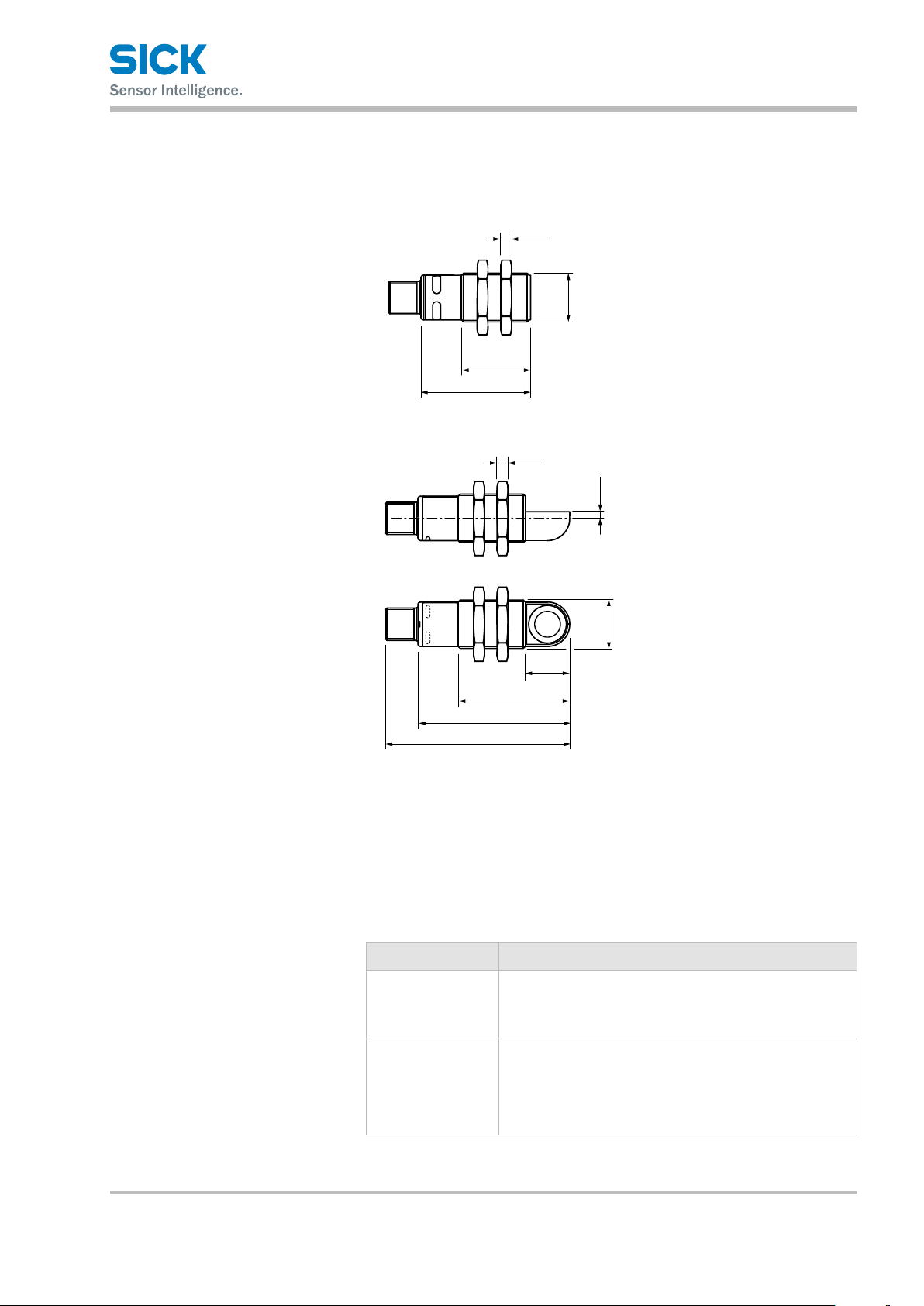
4 Structure and function
4
All dimensions in mm (inch)
1
4
(0.13)
1
4.1 Structure and status indicators
4
3
40.5 (1.59)
Structure and function
(0.16)
M18 x 1
2
25.5 (1.00)
2
(0.16)
3.4
3
4
16
41.5 (1.63)
56.5 (2.22)
68.5 (2.70)
Fig. 2: Structure: top "UM18-2xxxxxxx1 ultrasonic sensor"
bottom "UM18-2xxxxxxx2 ultrasonic sensor"
1 Connection
2 Mounting nuts, width across 24 mm
3 Supply voltage active LED status indicator (green)
4 Switching/analog output LED status indicator (orange)
(0.63)
M18 x 1
Status indicators (LEDs)
8014865/ZUJ3/2018-11-29 • © SICK AG • Subject to change without notice 13
Status display Description
Green Supply voltage
• Green LED: Supply voltage on
• LED o: Supply voltage o
Orange
Table 2: Status indicators (LEDs)
Switching/analog output
• LED orange: Switching output active/measured value
within analog output scaling
• LED o: Switching output inactive/measured value
outside analog output scaling
Page 14

Structure and function
4.2 Function
The UM18-2 Pro is an ultrasonic sensor for performing non-contact
distance measurement or detection of objects, animals, and persons.
The circuit variations have the following operation modes: Distance to
Object (DtO), Window (Wnd), and Object between Sensor and Background
(ObSB). The measured distance value is transferred cyclically over an
IO-Link interface.
Depending on the model, the analog versions output a voltage or current
value corresponding to the measured distance value and the scaling on
the customer side.
14 © SICK AG • Subject to change without notice • 8014865/ZUJ3/2018-11-29
Page 15
5 Mounting
1
2
5.1 Mounting the ultrasonic sensor
Mounting
NOTE!
Distance measurement is not possible within the blind
zone of the ultrasonic sensor. → See Page 42,
Chapter 11.2.
NOTE!
→ For mounting accessories, see Internet
"www.sick.com/um18", Accessories.
1. Select the mounting location for the ultrasonic sensor according to
the requirement. Keep in mind the specications in the technical
data, such as the detection range. → For dimensions, see Page 41,
Chapter 11.1. → For detection range, see Page 46, Chapter 11.9.
2. Insert the ultrasonic sensor through the hole in the mounting bracket.
3. Tighten mounting nuts using a maximum torque of 15 Nm.
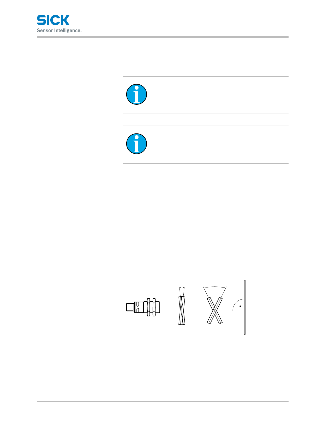
5.2 Smooth object surfaces
For smooth object surfaces, we recommend an angle of 90° ± 3° between
the sensor axis and the object surface. A larger angle is possible for rough
surfaces.
≤ ± 3° ≥ ± 3°
Fig. 3: Alignment of the sensor for smooth and rough object surfaces
1 Alignment for smooth object surfaces
2 Alignment for rough object surfaces
8014865/ZUJ3/2018-11-29 • © SICK AG • Subject to change without notice 15
Page 16

Mounting
5.3 Mounting multiple ultrasonic sensors
5.3.1 Minimum mounting distances
If you would like to operate multiple ultrasonic sensors and the mount-
ing distance is lower than the value specied in Table 3 (page 16), we
recommend using synchronization or multiplex mode. Synchronization or
multiplex mode avoids mutual interference between the sensors.
→ For synchronization mode, see Page 16, Chapter 5.3.2.
→ For multiplex mode, see Page 17, Chapter 5.3.3.
Minimum mounting distances
withoutsynchronizationmodeor
multiplex mode
Ultrasonic sensor Minimum distance for
parallel mounting
UM18-217x > 250 mm > 1300 mm
UM18-211x > 350 mm > 2500 mm
UM18-212x > 400 mm > 2500 mm
UM18-218x > 700 mm > 4000 mm
Table 3: Minimum mounting distances without synchronization mode or
multiplex mode
Minimumdistancewhen
devicesaremounted
opposite one another
5.3.2 Synchronizationmode
NOTE!!
The synchronization mode is not available in IO-Link
mode.
Descriptionofsynchronizationmode Synchronization mode begins automatically as soon as the sensors are
interconnected via PIN 5 (MF).
The sensors measure simultaneously in synchronization mode.
This operating mode prevents unwanted mutual interference since
measurements from dierent times are not incorrectly compared with one
another. The sensors can therefore be mounted without taking into account
mounting distances.
The acoustic pulses of a sensor deected by an object can still be analyzed
by neighboring sensors. This makes it possible to implement more reliable
and simultaneous monitoring of large areas with synchronization mode, but
without position detection of the recorded objects.
The detection zone is enlarged to a size which covers all synchronized
sensors. A maximum of 20 sensors of type UM18-2 Pro can be connected,
and they can also be combined with synchronizable SICK ultrasonic
sensors from other product families.
The response time of the overall system is determined by the sensor with
the highest response time.
16 © SICK AG • Subject to change without notice • 8014865/ZUJ3/2018-11-29
Page 17

Synchronizationmodestructureand
t
operating principle
5.3.3 Multiplex mode
Mounting
PIN 5
Fig. 4: Synchronization mode
NOTE!!
The multipex mode is not available in IO-Link mode.
Description of multiplex mode To change to multiplex mode, sensors must be interconnected via
PIN 5 (MF) and dierent addresses must be assigned to them using the
Connect+ software.
In multiplex mode, all sensors measure in alternation in a dened
sequence. This operating mode prevents unwanted mutual interference
since measurements from dierent times cannot be incorrectly compared
with one another. The sensors can therefore be mounted without taking
into account mounting distances.
Thanks to alternating measurement, the monitoring of large areas is
possible with additional position detection of recorded objects.
The detection zone is enlarged to a size which covers all connected
sensors. A maximum of 20 sensors of type UM18-2 Pro can be connected,
and they can also be combined with synchronizable SICK ultrasonic
sensors from other product families.
Since measurement by the sensors is done in alternation, the response
time of the total system is increased in accordance with the “overall
response time” formula.
NOTE!
For multiplex mode, you must assign a unique address to
the sensors. The "Connect + Adapter" and the associated
software is required for this (order no. 6037782)
8014865/ZUJ3/2018-11-29 • © SICK AG • Subject to change without notice 17
Page 18

t
Mounting
Overallresponsetime Response time
n: Number of connected sensors
Multiplex mode structure and operating principle
PIN 5
Fig. 5: Multiplex mode
= 4 • [(1.1 ms • n) + 0.75 ms • (1 + 2 + … + n)] +
overall
sum of the response times of all connected sensors
18 © SICK AG • Subject to change without notice • 8014865/ZUJ3/2018-11-29
Page 19

6 Electrical connection
6.1 Safety
Incorrectsupplyvoltage
Workingwithliveparts
Electrical connection
IMPORTANT!
Equipmentdamageduetoincorrectsupplyvoltage!
An incorrect supply voltage may result in damage to
the equipment.
For this reason:
• Operate the ultrasonic sensor using only a protected
low voltage and safe electrical insulation as per
Protection Class III.
IMPORTANT!
6.2 Wiring notes
Equipment damage or unpredictable operation due to
workingwithliveparts!
Working with live parts may result in unpredictable
operation.
For this reason:
• Carry out wiring work only when the power is o.
• Connect and disconnect cable connections only when
the power is o.
IMPORTANT!
Faultsduetoincorrectwiring!
Incorrect wiring may result in operational faults.
For this reason:
• Follow the wiring notes precisely.
NOTE!
We recommend using preassembled cables for
the wiring. → For preassembled cables, see Internet
"www.sick.com/um18", Accessories.
8014865/ZUJ3/2018-11-29 • © SICK AG • Subject to change without notice 19
Page 20

Electrical connection
All electrical connections of the ultrasonic sensor are congured as M12
round connectors.
The IP 67 protection class is only achieved using screwed plug connectors
or cover caps.
By using suitable cable entries and wiring, you can avoid interference
from devices such as switching power supplies, motors, clocked drives,
and contactors.
• Lay cables as far away as possible from cables having a high level of
radiated emission. If needed, employ additional measures such as
shielding plates.
• Do not lay cables parallel to other cables, particularly devices with a high
level of radiated emission, such as frequency converters.
• Do not lay cables parallel to energy cables.
6.3 Connecting the ultrasonic sensor electrically
1. Ensure that there is no voltage.
2. Connect the ultrasonic sensor according to the connection diagram.
→ See Page 21, Chapter 6.4.
20 © SICK AG • Subject to change without notice • 8014865/ZUJ3/2018-11-29
Page 21

6.4 Connection diagrams
Q/C
1
2
3
5
Q/Q/C
NOTE!
The lead colors specied in Sections 6.4.1 and 6.4.2
apply to SICK AG's preassembled cables. The lead
colors may vary for preassembled cables from other
manufacturers.
→ For preassembled cables, see Internet
"www.sick.com/en/um18", Accessories.
6.4.1 Ultrasonicsensorswithswitchingoutputs
Electrical connection
UM18-21xxxAxxx
1
brn
L+
4
blk
blu
wht
gra
Q/¯
3
M
2
nc
5
MF
4
Fig. 6: UM18-21xxxAxxx connection diagram,
M12 plug, 5-pin, A-coded
Contact Marking Wire color Description
1 L+ Brown Supply voltage:
→ See Page 43, Chapter 11.3.
2 Nc White Not assigned
3 M Blue Supply voltage: 0 V
4
5 MF Gray Multifunction input/output for
Black Switching output /
IO-Link communication
• External teach-in
• Synchronization mode/multiplex
mode
• Connect+ communication
Table 4: Description of UM18-21xxxAxxx plug
8014865/ZUJ3/2018-11-29 • © SICK AG • Subject to change without notice 21
Page 22

1
2
3
5
Electrical connection
6.4.2 Ultrasonicsensorswithanalogoutputs
UM18-21xxx6xxx,
UM18-21xxx7xxx
1
brn
L+
4
blk
blu
wht
gra
nc
3
M
2
Q
A
5
MF
4
Fig. 7: UM18-21xxx6xxx (4 … 20 mA) and UM18-21xxx7xxx (0 … 10 V)
connection diagram, M12 plug, 5-pin, A-coded
Contact Marking Wire color Description
1 L+ Brown Supply voltage:
→ See Page 43, Chapter 11.3.
2 Q
A
3 M Blue Supply voltage: 0 V
4 Nc Black Not assigned
5 MF Gray Multifunction input/output for
White Analog output
• External teach
• Synchronization mode/multiplex
mode
• Connect+ communication
Table 5: Description of UM18-21xxx6xxx and UM18-21xxx7xxx plugs
22 © SICK AG • Subject to change without notice • 8014865/ZUJ3/2018-11-29
Page 23

Commissioning
1
1
7 Commissioning
7.1 Ultrasonicsensorswithswitchingoutputs
→ For a graphical overview of the various setup options,
see Page 49, Chapter 13.1 and Page 50, Chapter 13.3.
7.1.1 Teach-intheswitchingpoint–methodA
Distance to object (DtO) In method A, the switching output is set when the object is located within
the taught-in switching range. The orange LED lights up when the switching
output is active.
Fig. 8: Teach-in the switching point – method A
1 Switching point
1. Position object at 1.
2. Apply "L+" to "MF" for approximately 3 seconds until both LEDs ash
simultaneously.
3. When both LEDs ash alternately, apply "L+" for approximately
1 second to "MF".
b The ultrasonic sensor's switching point has been taught-in.
The ultrasonic sensor is in normal operational mode.
Congure the switching output as normally closed or normally open.
→ See Page 25, Chapter 7.1.5.
7.1.2 Teach-intheswitchingpoint–methodB
Distance to object (DtO) In method B, the switching output is set when the object is located within
the taught-in switching range plus 8 %. The orange LED lights up when
the switching output is active.
+ 8 %
Fig. 9: Teach-in the switching point – Method B
1 Switching point
8014865/ZUJ3/2018-11-29 • © SICK AG • Subject to change without notice 23
Page 24

21
1
Commissioning
1. Position object at 1.
2. Apply "L+" to "MF" for approximately 3 seconds until both LEDs ash
simultaneously.
3. When both LEDs ash alternately, apply "L+" to "MF" for approximately
3 seconds until both LEDs again ash alternately.
b The ultrasonic sensor's switching point has been taught-in.
The ultrasonic sensor is in normal operational mode.
Congure the switching output as normally closed or normally open.
→ See Page 25, Chapter 7.1.5.
7.1.3 Teach-inthewindow
Window The switching output is set when the object is located within the window.
The orange LED lights up when the switching output is active.
Fig. 10: Teach-in the window
1 Switching point 1
2 Switching point 2
1. Position object at 1.
2. Apply "L+" to "MF" for approximately 3 seconds until both LEDs ash
3. When both LEDs ash alternately, position object at 2.
4. Apply "L+" to "MF" for approximately 1 second.
b The ultrasonic sensor's switching point has been taught-in.
Congure the switching output as normally closed or normally open.
→ See Page 25, Chapter 7.1.5.
7.1.4 Teach-in the background
ObjectbetweenSensorand
Background(ObSB)
The output is set when the object is located between the sensor and a xed
background. The orange LED lights up when the switching output is active.
Even at changing ambient conditions the object is detected in the range of
0 % ... 85 % of the taught-in distance.
simultaneously.
The ultrasonic sensor is in normal operational mode.
85 %
Fig. 11: Teach-in the background
1 Background
24 © SICK AG • Subject to change without notice • 8014865/ZUJ3/2018-11-29
Page 25

1. Position object at 1.
12
2. Apply "L+" to "MF" for approximately 3 seconds until both LEDs ash
simultaneously.
3. When both LEDs ash alternately, apply "L+" to "MF" for approximately
10 seconds until both LEDs stop ashing.
b The ultrasonic sensor's switching point has been taught-in.
The ultrasonic sensor is in normal operational mode.
Congure the switching output as normally closed or normally open.
→ See Page 25, Chapter 7.1.5.
7.1.5 Conguringasnormallyopenornormallyclosed
Factory setting: normally open
1. Apply "L+" to "MF" for approximately 13 seconds until both LEDs ash
alternately.
2. The green LED ashes. The orange LED indicates the current setting:
Commissioning
• On: normally open
• O: normally closed
3. To change the setting, apply "L+" to "MF" for approximately 1 second.
The orange LED changes its status.
4. After conguring, wait approximately 10 seconds until the green LED
stops ashing.
b The setting has been applied. The ultrasonic sensor is in normal
operational mode.
7.2 Ultrasonicsensorswithananalogoutput
→ For a graphical overview of the various setup options,
see Page 49, Chapter 13.2 and Page 50, Chapter 13.3.
7.2.1 Conguringthescalingoftheanalogoutput
The orange LED lights up when the object is located within the congured
scaling.
The minimum distance between the two scaling limits is 1 mm. A failed
teach-in is indicated by the simultaneous rapid ashing of both LEDs.
The original settings are retained.
Fig. 12: Teach-in the analog output
1 Scaling limit near the sensor
2 Scaling limit away from the sensor
8014865/ZUJ3/2018-11-29 • © SICK AG • Subject to change without notice 25
Page 26

Commissioning
1. Position object at 1.
2. Apply "L+" to "MF" for approximately 3 seconds until both LEDs ash
simultaneously.
3. When both LEDs ash alternately, position object at 2.
4. Apply "L+" to "MF" for approximately 1 second.
b The analog output has been taught-in. The ultrasonic sensor is in
normal operational mode.
NOTE!
You can teach-in the limit near the sensor or the limit
away from the sensor rst. You can teach-in the output
characteristics afterwards. → See the following section.
7.2.2 Conguringtherisingorfallingoutputcharacteristiccurve
Factory setting: "Rising output characteristic curve"
1. Apply "L+" to "MF" for approximately 13 seconds until both LEDs ash
alternately.
2. The green LED ashes. The orange LED indicates the current setting:
• On: Rising output characteristic curve
• O: Falling output characteristic curve
3. To change the setting, apply "L+" to "MF" for approximately 1 second.
The orange LED changes its status.
4. After conguring, wait approximately 10 seconds until the green LED
stops ashing.
b The setting has been applied. The ultrasonic sensor is in normal
operational mode.
7.3 Additional settings for all sensor models
7.3.1 Switchingbetweenteach-inandsynchronization/multiplexmode
NOTE!
The teach-in functionality is deactivated when
synchronization/multiplex mode is activated.
For synchronization/multiplex mode, the ultrasonic
sensors must be interconnected via the "MF" input (pin
5). You can operate a maximum of 20 UM18-2 Pro
sensors in synchronization/multiplex mode.
26 © SICK AG • Subject to change without notice • 8014865/ZUJ3/2018-11-29
Page 27

Commissioning
Factory setting: Teach-in
1. Switch o the supply voltage.
2. Apply "M" to "MF".
3. Switch on the supply voltage and wait approximately 3 seconds until
both LEDs ash simultaneously.
4. The green LED ashes. The orange LED indicates the current setting:
• On: Teach-in
• O: Synchronization/multiplex mode
5. To change the setting, apply "M" to "MF" for approximately 1 second.
The orange LED changes its status.
6. After conguring, wait approximately 10 seconds until the green LED
stops ashing.
b The setting has been applied. The ultrasonic sensor is in normal
operational mode.
→ For additional information about synchronization/multiplex mode and
the minimum mounting distances without synchronization/multiplex mode,
see Page 16, Chapter 5.3.
7.3.2 Resetting the settings to the factory setting
1. Switch o the supply voltage.
2. Apply "M" to "MF".
3. Switch on the supply voltage and wait approximately 13 seconds until
both LEDs stop ashing.
4. Before switching o the supply voltage, disconnect "M" from "MF" in
order to apply the factory setting.
b All settings have been reset to the factory setting. The ultrasonic
sensor is in normal operational mode.
8014865/ZUJ3/2018-11-29 • © SICK AG • Subject to change without notice 27
Page 28

Commissioning
7.4 Temperature compensation
The UM18-2 Pro sensors feature internal temperature compensation. Due
to the sensor heating up, the temperature compensation function will reach
its optimal working point after approximately one minute.
Temperature compensation is calibrated for standard mounting condi-
tions, using an aluminum mounting bracket and mounting screws, at the
factory. It is automatically and optimally calibrated to the individual installation situation when the sensor is cold and the switching output has been
deactivated for approx. 30 min., or the analog output has been outputting
a constant value of between 11 and 13 mA or 4.4. and 5.6 V for approx.
30 min. If the measured value changes over the course of these 30 min.,
the calibration process running in the background is aborted. The standard
parameters or the parameters last calibrated are retained. This function is
very helpful when the installation situation diers greatly from the standard
mounting conditions (e.g. in the case of thermally insulated mounting) and
a very high level of accuracy is required.
Temperature compensation can be switched o via
“Connect+ Adapter,” not temperature-compensated: 0.17 %/K
28 © SICK AG • Subject to change without notice • 8014865/ZUJ3/2018-11-29
Page 29

Commissioning
7.5 Measuredvaluelter
Filter settings The following lter settings can be selected for the UM18-2 Pro ultrasonic
sensors using "Connect+ Adapter":
Filter F00 provides an unltered output for the measured values.
This mode is not permitted, as undesired EMC faults could result.
Decreasing distance values are checked by lters F01 and F02 only for
plausibility and then output without any further conditions. After checking
for plausibility, increasing distance values are tracked only if they do not
exceed a specied tolerance range for the rate of increase. If the deviations
are too great, they are classied as interference variables by the software
and bridged for an adjustable holding time according to lter strength P.
Filter F01 provides interference protection against individual pulses such
as EMC spikes in connection with protection against measured value jumps
that are away from the sensor. The lter is suitable for bridging signal
jumps.
Filter F02 provides interference protection against individual pulses
such as EMC spikes in connection with protection against very brief
measured value jumps away from the sensor. The lter reacts very quickly
to measured values near the sensor and provides a smoothed output of
measured values based on approximately arithmetic averaging. This lter
is therefore especially suitable for smoothing uctuating measured values.
Smoothing according to the lter strength P.
Filter F03 and F04 do not include a plausibility check. Thereby they waive
an interference protection against single interfering impulses and thus
resulting measurement value jumps with direction to smaller (F03) or larger
(F04) distance values. In return they react very quickly to measurement
value changes in the preferred distance level (F03: near sensor; F04: away
from sensor) and provide a smoothed output of measurement values in
this distance level, according to lter strength P.
In the opposite direction an adjustable holding time as well as an averaging
take eect, both operating according to lter strength P.
With lter F03 background reections of unexpected objects are faded out.
With lter F04 foreground reections of unexpected objects (e.g. stirring
tools) are faded out.
Filteroverview
Filter feature Plausibility check Dwelltime Preferred distance
level
Functionality Interference
protection against
individual pulses
(EMC)
Filter F00 (No lter) No No No preference No
F01 (Approximation lter) Ye s Yes Near sensor No
F02 (Average value lter) Ye s Low Near sensor Yes
F03 (Foreground lter) No Yes Near sensor Yes
F04 (Background lter) No Yes Away from sensor Yes
Table 6: Filter overview
Bridging measured
value jumps
Near sensor/away
from sensor
Averaging
"Smoothing"
the output of
measured values
8014865/ZUJ3/2018-11-29 • © SICK AG • Subject to change without notice 29
Page 30

Commissioning
Filter parameters
Filter type (F) Filter strength (P) Plausibility check Holding time
overxcycles
F00 – No No No No
F01 0 (factory setting) Ye s 4 Near sensor No
1 Yes 8 Near sensor No
2 Yes 12 Near sensor No
3 Yes 16 Near sensor No
4 Yes 20 Near sensor No
5 Yes 50 Near sensor No
6 Yes 100 Near sensor No
7 Yes 200 Near sensor No
8 Yes 500 Near sensor No
9 Yes 1000 Near sensor No
F02 0 Yes 4 Near sensor 2
1 (factory setting) Ye s 4 Near sensor 4
2 Yes 8 Near sensor 6
3 Yes 8 Near sensor 8
4 Yes 8 Near sensor 10
5 Yes 8 Near sensor 20
6 Yes 8 Near sensor 32
7 Yes 8 Near sensor 64
8 Yes 8 Near sensor 128
9 Yes 8 Near sensor 255
F03 0 Yes 4 Near sensor 1
1 Yes 8 Near sensor 2
2 Yes 12 Near sensor 3
3 Yes 16 Near sensor 4
4 Yes 20 Near sensor 8
5 Yes 50 Near sensor 16
6 Yes 100 Near sensor 32
7 Yes 200 Near sensor 64
8 Yes 500 Near sensor 128
9 Yes 1000 Near sensor 255
F04 0 Ja 4 Away from sensor 1
1 Ja 8 Away from sensor 2
2 Ja 12 Away from sensor 3
3 Ja 16 Away from sensor 4
4 Ja 20 Away from sensor 8
5 Ja 50 Away from sensor 16
6 Ja 100 Away from sensor 32
7 Ja 200 Away from sensor 64
8 Ja 500 Away from sensor 128
9 Ja 1000 Away from sensor 255
Table 7: Filter parameters
Preferred distance
level
Averaging
overxcycles
30 © SICK AG • Subject to change without notice • 8014865/ZUJ3/2018-11-29
Page 31

Commissioning
Cycle time The cycle time corresponds to the measuring interval of the respective
sensor type.
UM18-217xxxxxx: 8 ms
UM18-211xxxxxx: 8 ms
UM18-212xxxxxx: 16 ms
UM18-218xxxxxx: 20 ms
Factory setting • Sensors with switching output: lter type F01 and lter strength 0
• Sensors with analog output: lter type F02 and lter strength 1
Foreground suppression Use foreground suppression to suppress stray reections caused by
objects in the vicinity of the sensor.
NOTE!
Interfering objects must not create multiple reections.
The ultrasonic sensor must not be covered by interfering
objects that aect the detection range.
8014865/ZUJ3/2018-11-29 • © SICK AG • Subject to change without notice 31
Page 32

IO-Link interface
8 IO-Link interface
8.1 Physical layer
The ultrasonic sensors with switching outputs are IO-Link-capable in
accordance with the V1.1 specication.
You can download the specic sensor IO-Link device description online
from "www.sick.com/um18".
NOTE!
If an ultrasonic sensor in SIO mode has been taught-in
via teach-in or via a "Connect+ Adapter," we recommend
resetting the sensor to its factory setting before
conguration using IO-Link.
Description Value
SIO mode
(standard I/O mode)
Output rate • UM18-217xxxxxx: 8 ms
Speed COM2 (38.4 kBaud)
Process data width 16 bits (frame type 2.2)
Table 8: Physical layer
Yes
• UM18-211xxxxxx: 8 ms
• UM18-212xxxxxx: 16 ms
• UM18-218xxxxxx: 20 ms
32 © SICK AG • Subject to change without notice • 8014865/ZUJ3/2018-11-29
Page 33

IO-Link interface
8.2 Process data
The process data for the UM18-2 Pro ultrasonic sensors has a data width
of 16 bits.
Description Value
Access Read
Data 2 bytes
Data type UINT (unsigned integer)
Table 9: Process data
MSB LSB
Bit 15 Bit 14 Bit 13 Bit 12 Bit 11 Bit 10 Bit 9 Bit 8 Bit 7 Bit 6 Bit 5 Bit 4 Bit 3 Bit 2 Bit 1 Bit 0
Distance value (15-bit) with a resolution of 0.1 mm Q
Table 10: Data format – process data, distance value, and switching output Q
8.3 Servicedata
8.3.1 IO-Link-specic
Index
decimal
(hex)
16 (0x10) Manufacturer
17 (0x11) Manufacturer text R www.sick.com –
18 (0x12) Product name R UM18-2 –
19 (0x13) Product ID R UM18-21212A21 Sensor description
20 (0x14) Product text R Ultrasonic sensor –
22 (0x16) Hardware version R 5.0 –
23 (0x17) Firmware version R 1.0.42 –
Table 11: IO-Link-specic service data
Description Format Access Value range Example Remarks
R SICK AG
name
→ See IO-Link
specication.
8014865/ZUJ3/2018-11-29 • © SICK AG • Subject to change without notice 33
Page 34

IO-Link interface
8.3.2 SICK-specicUM18-21712A21_
Index
Description Format Access Value range Example Remarks
decimal
(hex)
64 (0x40) Switching point 1 UINT16 R/W 306 ... 3609
(21 ... 248 mm)
65 (0x41) Switchback point 1 UINT16 R/W 320 ... 3624
(22 ... 249 mm)
71 (0x47) Switching point 2 UINT16 R/W 335 ... 65512
(23 ... 250 mm)
72 (0x48) Switchback point 2 UINT16 R/W 335 ... 65512
(23 ... 250 mm)
73 (0x49) Foreground
suppression
66 (0x42) Switching output
function
67 (0x43) Filter UINT8 R/W • 00: F00
UINT8 R/W 0 ... 1878
(0 ... 129 mm)
UINT8 R/W • 00: normally closed
• 02: normally open
2)
• 01: F01
• 02: F02
68 (0x44) Filter strength UINT8 R/W • 00: P00
• 01: P01
• 02: P02
• 03: P03
• 04: P04
• 05: P05
• 06: P06
• 07: P07
• 08: P08
• 09: P09
74 (0x4A) Teach via pin 5 in
SIO mode
UINT8 R/W • 00: deactivated
• 16: activated
320 corresponds
to
22 mm
Specify values
1)
as a multiple
of the internal
measurement value
1)
resolution (0.069 m).
–
→ See also
Page 29,
Chapter 7.5.
For the selected
measured value lter,
you can select a lter
strength between 0
(weak ltering eect)
and 9 (strong ltering
eect).
–
Teach
Index
decimal
(hex)
02 (0x02) TE ACH UINT W • 161: Method A
Description Format Access Value range Example Remarks
A teach overwrites
• 162: Method B
• 164: Two-way
reection barrier
• 168: Reset to
factory setting
a function that has
already been set with a
newly selected function.
If a teach is successful,
the old value is
retained.
→ See Page 23,
Chapter 7.1
and Page 49,
Chapter 13.1.
1) Window operation deactivated for values > 3638.
2) Operation with lter setting "F00" is not permitted, as EMC faults may occur in this case.
Table 12: SICK-specic service data UM18-21712A21_
34 © SICK AG • Subject to change without notice • 8014865/ZUJ3/2018-11-29
Page 35

8.3.3 SICK-specicUM18-21712A21_
IO-Link interface
Index
Description Format Access Value range Example Remarks
decimal
(hex)
64 (0x40) Switching point 1 UINT16 R/W 436 ... 5065
(30 ... 348 mm)
65 (0x41) Switchback point 1 UINT16 R/W 451 ... 5080
(31 ... 349 mm)
71 (0x47) Switching point 2 UINT16 R/W 466 ... 65512
(32 ... 350 mm)
72 (0x48) Switchback point 2 UINT16 R/W 451 ... 65512
(31 ... 349 mm)
73 (0x49) Foreground
suppression
66 (0x42) Switching output
function
67 (0x43) Filter UINT8 R/W • 00: F00
UINT8 R/W 0 ... 3246
(0 ... 223 mm)
UINT8 R/W • 00: normally closed
• 02: normally open
2)
• 01: F01
• 02: F02
68 (0x44) Filter strength UINT8 R/W • 00: P00
• 01: P01
• 02: P02
• 03: P03
• 04: P04
• 05: P05
• 06: P06
• 07: P07
• 08: P08
• 09: P09
74 (0x4A) Teach via pin 5 in
SIO mode
UINT8 R/W • 00: deactivated
• 16: activated
800 corresponds
to 55 mm
Specify values
1)
as a multiple
of the internal
1)
measurement value
resolution (0.069 mm).
–
→ See also Page 29,
Chapter 7.5.
For the selected
measured value lter,
you can select a lter
strength between 0
(weak ltering eect)
and 9 (strong ltering
eect).
–
Teach
Index
decimal
(hex)
02 (0x02) TE ACH UINT W • 161: Method A
Description Access Access Value range Example Remarks
A teach overwrites
• 162: Method B
• 164: Two-way
reection barrier
• 168: Reset to
factory setting
a function that has
already been set
with a newly selected
function.
If a teach is not
successful, the old
value is retained.
→ See Page 23,
Chapter 7.1
and Page 49,
Chapter 13.1.
1) Window operation deactivated for values > 5094.
2) Operation with lter setting "F00" is not permitted, as EMC faults may occur in this case.
Table 13: SICK-specic service data UM18-21112A21_
8014865/ZUJ3/2018-11-29 • © SICK AG • Subject to change without notice 35
Page 36

IO-Link interface
8.3.4 SICK-specicUM18-21212A21_
Index
Description Format Access Value range Example Remarks
decimal
(hex)
64 (0x40) Switching point 1 UINT16 R/W 946 ... 8704
(65 ... 598 mm)
65 (0x41) Switchback point 1 UINT16 R/W 961 ... 8718
(66 ... 599 mm)
71 (0x47) Switching point 2 UINT16 R/W 975 ... 65512
(67 ... 600 mm)
72 (0x48) Switchback point 2 UINT16 R/W 961 ... 65512
(66 ... 599 mm)
73 (0x49) Foreground
suppression
66 (0x42) Switching output
function
67 (0x43) Filter UINT8 R/W • 00: F00
UINT8 R/W 0 ... 4236
(0 ... 291 mm)
UINT8 R/W • 00: normally closed
• 02: normally open
2)
• 01: F01
• 02: F02
68 (0x44) Filter strength UINT8 R/W • 00: P00
• 01: P01
• 02: P02
• 03: P03
• 04: P04
• 05: P05
• 06: P06
• 07: P07
• 08: P08
• 09: P09
74 (0x4A) Teach via pin 5 in
SIO mode
UINT8 R/W • 00: deactivated
• 16: activated
100 corresponds
to 69 mm
Specify values
1)
as a multiple
of the internal
1)
measurement value
resolution (0.069 mm).
–
→ See also Page 29,
Chapter 7.5.
For the selected
measured value lter,
you can select a lter
strength between 0
(weak ltering eect)
and 9 (strong ltering
eect).
–
Teach
Index
decimal
(hex)
02 (0x02) TE ACH UINT W • 161: Method A
Description Format Access Value range Example Remarks
A teach overwrites
• 162: Method B
• 164: Two-way
reection barrier
• 168: Reset to
factory setting
a function that has
already been set
with a newly selected
function.
If a teach is not
successful, the old
value is retained.
→ See Page 23,
Chapter 7.1
and Page 49,
Chapter 13.1.
1) Window operation deactivated for values > 8733.
2) Operation with lter setting "F00" is not permitted, as EMC faults may occur in this case.
Table 14: SICK-specic service data UM18-21212A21_
36 © SICK AG • Subject to change without notice • 8014865/ZUJ3/2018-11-29
Page 37

8.3.5 SICK-specicUM18-21812A21_
IO-Link interface
Index
Description Format Access Value range Example Remarks
decimal
(hex)
64 (0x40) Switching point 1 UINT16 R/W 1747 ... 18892
(120 ... 1298 mm)
65 (0x41) Switchback point 1 UINT16 R/W 1761 ... 18907
(121 ... 1299 mm)
71 (0x47) Switching point 2 UINT16 R/W 1776 ... 65512
(122 ... 1300 mm)
72 (0x48) Switchback point 2 UINT16 R/W 1761 ... 65512
(121 ... 1299 mm)
73 (0x49) Foreground
suppression
66 (0x42) Switching output
function
67 (0x43) Filter UINT8 R/W • 00: F00
UINT8 R/W 0 ... 12969
(0 ... 891 mm)
UINT8 R/W • 00: normally closed
• 02: normally open
2)
• 01: F01
• 02: F02
68 (0x44) Filter strength UINT8 R/W • 00: P00
• 01: P01
• 02: P02
• 03: P03
• 04: P04
• 05: P05
• 06: P06
• 07: P07
• 08: P08
• 09: P09
74 (0x4A) Teach via pin 5 in
SIO mode
UINT8 R/W • 00: deactivated
• 16: activated
2000 corresponds
to 138 mm
1)
1)
Specify values
as a multiple
of the internal
measurement value
resolution (0.069 mm).
–
→ See also Page 29,
Chapter 7.5.
For the selected
measured value lter,
you can select a lter
strength between 0
(weak ltering eect)
and 9 (strong ltering
eect).
–
Teach
Index
decimal
(hex)
02 (0x02) TE ACH UINT W • 161: Method A
Description Format Access Value range Example Remarks
A teach overwrites
• 162: Method B
• 164: Two-way reec-
tion barrier
• 168: Reset to factory setting
a function that has
already been set
with a newly selected
function.
If a teach is successful,
the old value is
retained.
→ See Page 23,
Chapter 7.1
and Page 49,
Chapter 13.1.
1) Window operation at value.
2) Operation with lter setting "F00" is not permitted, as EMC faults may occur in this case.
Table 15: SICK-specic service data UM18-21812A21_
8014865/ZUJ3/2018-11-29 • © SICK AG • Subject to change without notice 37
Page 38

IO-Link interface
8.4 Error Codes
→ For error codes, see IO-Link specication V1.1.
38 © SICK AG • Subject to change without notice • 8014865/ZUJ3/2018-11-29
Page 39

9 Cleaning and maintenance
9.1 Cleaning
Cleaning and maintenance
IMPORTANT!
Equipment damage due to improper cleaning!
Improper cleaning may result in equipment damage.
For this reason:
• Never use cleaning agents containing aggressive
substances.
• Never use pointed objects for cleaning.
9.2 Maintenance
The ultrasonic sensor requires the following maintenance work at regular
intervals:
Interval Maintenancework To be performed by
Cleaning interval depends
on ambient conditions and
climate
Every 6 months Check the screw connections and plug connections. Specialist
Table 16: Maintenance schedule
Clean housing. Specialist
8014865/ZUJ3/2018-11-29 • © SICK AG • Subject to change without notice 39
Page 40

Troubleshooting
10 Troubleshooting
10.1 Possible fault indicators
LEDs on the ultrasonic sensor Possible causes Troubleshooting
Green and orange LEDs
ash at the same rate for
3 seconds.
Table 17: Possible fault indicators
10.2 Disposal
Teach point is outside the permitted range. Check teach distance and perform teach
again.
Teach failed, for example, due to interfering
reections or mounting distances that are
too small when using multiple sensors.
Analog output only: Taught-in distance
between the scaling limits is below 1 mm.
• Check the sensor detection zone and keep
free. If necessary, shield existing sources
of interference.
• When using multiple sensors, observe
minimum mounting distances without
synchronization mode and operate
sensors in synchronization mode if
necessary.
→ See Page 16, Chapter 5.3.2.
Repeat teach for window limits.
Please observe the following when disposing of the removal sensor:
• Do not dispose of the device along with household waste.
• Dispose of the device according to the applicable regulations in your
country.
40 © SICK AG • Subject to change without notice • 8014865/ZUJ3/2018-11-29
Page 41

11 Technical data
4
All dimensions in mm (inch)
1
4
(0.13)
1
11.1 Dimensions
Technical data
NOTE!
You can download, save, and print the relevant online
data sheet for your ultrasonic sensor, including technical
data, dimensions, and connection diagrams,
from "www.sick.com/UM18".
(0.16)
4
M18 x 1
3
2
25.5 (1.00)
40.5 (1.59)
2
(0.16)
3.4
3
4
16
41.5 (1.63)
56.5 (2.22)
68.5 (2.70)
Fig. 13: Structure: top "UM18-2xxxxxxx1 ultrasonic sensor"
1 Connection
2 Mounting nuts, width across 24 mm
3 Supply voltage active LED status indicator (green)
4 Switching/analog output LED status indicator (orange)
bottom "UM18-2xxxxxxx2 ultrasonic sensor"
(0.63)
M18 x 1
8014865/ZUJ3/2018-11-29 • © SICK AG • Subject to change without notice 41
Page 42

Technical data
11.2 Optics/Performance
Detection areas (typical) → See Page 46, Chapter 11.9, "”Detection zone” diagrams".
Operating range • UM18-217xxxxxx: 20 mm ... 150 mm
• UM18-211xxxxxx: 30 mm ... 250 mm
• UM18-212xxxxxx: 65 mm ... 350 mm
• UM18-218xxxxxx: 120 mm ... 1000 mm
Limiting range • UM18-217xxxxxx: 250 mm
• UM18-211xxxxxx: 350 mm
• UM18-212xxxxxx: 600 mm
• UM18-218xxxxxx: 1300 mm
Accuracy ± 1 % in relation to the current measured value
Repeatability ± 0.15 % in relation to the current measured value
Temperature compensation • Temperature drift compensated internally
→ See Page 28, Chapter 7.4.
• Temperature compensation can be switched o via
"Connect+ Adapter," not temperature-compensated: 0.17 %/K
Resolution ≥ 0.069 mm
Ultrasonic frequency • UM18-217xxxxxx: 380 kHz
• UM18-211xxxxxx: 320 kHz
• UM18-212xxxxxx: 400 kHz
• UM18-218xxxxxx: 200 kHz
Output time • UM18-217xxxxxx: 8 ms
• UM18-211xxxxxx: 8 ms
• UM18-212xxxxxx: 16 ms
• UM18-218xxxxxx: 20 ms
Initialization time < 300 ms
Switching frequency • UM18-217xxxxxx: 25 Hz
• UM18-211xxxxxx: 25 Hz
• UM18-212xxxxxx: 12 Hz
• UM18-218xxxxxx: 10 Hz
Response time
1)
• UM18-217xxxxxx: 32 ms
• UM18-211xxxxxx: 32 ms
• UM18-212xxxxxx: 64 ms
• UM18-218xxxxxx: 80 ms
1) For sensors with analog output: depending on the application, subsequent smoothing of the analog signal may increase the response time
by up to 200 %.
Table 18: Performance data
42 © SICK AG • Subject to change without notice • 8014865/ZUJ3/2018-11-29
Page 43

11.3 Powersupply
11.3.1 Sensorswithswitchingoutputs
Technical data
Supply voltage V
1)
,
s
• DC 15 … 30 V
sensors with switching output
UM18-2xxxxxAxxx
Power consumption (without load) < 1.2 W
Residual ripple ± 10 % within the acceptable supply voltage V
1) Limit values: Max. 8 A for operation in a short-circuit protected network.
Table 19: Supply – sensors with switching outputs
11.3.2 Sensorswithanalogoutputs
Supply voltage V
sensors with switching output
UM18-2xxxxx7xx
Supply voltage V
sensors with switching output
UM18-2xxxxx6xx
Circuit protection V
Power consumption (without load) < 1.2 W
Residual ripple ± 10 % within the acceptable supply voltage V
1) Limit values: Max. 8 A for operation in a short-circuit protected network.
Table 20: Supply – sensors with analog outputs
1)
,
s
1)
,
s
DC 15 ... 30 V DC
• DC 10 … 30 V DC at RL ≤ 100 Ω
• DC 20 … 30 V DC at RL ≥ 100 Ω
connections, reverse polarity protected
s
s
s
11.4 Inputs
Multifunction input MF • Teach-in
• Connect+ communication
• Synchronization/multiplex mode
Table 21: Inputs
11.5 Outputs
11.5.1 Sensorswithswitchingoutputs
Sensors with switching outputs UM18-2xxxxAxxx
Switching output • Push-pull: PNP/NPN
• HIGH: V
• IO-Link
– (< 3 V), LOW: < 3 V
s
8014865/ZUJ3/2018-11-29 • © SICK AG • Subject to change without notice 43
Page 44

Technical data
Hysteresis • UM18-217xxxxxx: 2 mm
• UM18-211xxxxxx: 3 mm
• UM18-212xxxxxx: 5 mm
• UM18-218xxxxxx: 20 mm
Congurable via "Connect+ Adapter"
Circuit protection Short-circuit protected
Maximum output current < 100 mA
Table 22: Outputs – sensors with switching outputs
11.5.2 Sensorswithanalogoutputs
Sensors with analog outputs • UM18-2xxxx6xxx: 4 mA … 20 mA
• UM18-2xxxx7xxx: DC 0 … 10 V DC
Analog output
UM18-2xxxx6xxx
Analog output
UM18-2xxxx7xxx
• 4 mA … 20 mA
• RL ≤ 500 Ω, at V
• Rising, falling characteristic curve, congurable
• DC 0 … 10 V DC
• RL ≥ 100 Ω
≤ 20 V: max. load ≤ 100 Ω
s
• Rising, falling characteristic curve, congurable
Resolution 12 Bit
Circuit protection UM18-2xxxxx6xx: Voltage output is short-circuit protected
Table 23: Outputs – sensors with analog outputs
11.6 Interfaces
IO-Link For sensors with switching outputs
Connect+ Conguration interface for communication via "Connect+ Adapter"
accessories
Table 24: Interfaces
44 © SICK AG • Subject to change without notice • 8014865/ZUJ3/2018-11-29
Page 45

11.7 Ambient conditions
Protection class III
Electromagnetic compatibility
Ambient temperature range –25 °C … +70 °C
Storage temperature range –40 °C … +85 °C
Enclosure rating IP 67 according to EN 60529
1) Operation with lter setting "F00" is not permitted, as EMC faults may occur in this case.
Table 25: Ambient conditions
1)
EN 61000-6-2, EN 55011, Class A
EN 60947-5-2/-3
11.8 Structural design
Dimensions → See Page 41, Chapter 11.1.
Technical data
Weight • Straight: 25 g
• Angled: 30 g
Materials • Housing: Nickel-plated brass
• Ultrasonic transducer: polyurethane foam, glass epoxy resin
Connections Plug M12, 5-pin
Display • Green LED: operation
• Orange LED: on when switching/analog output is active
Table 26: Structural design
8014865/ZUJ3/2018-11-29 • © SICK AG • Subject to change without notice 45
Page 46

(1.97)
(9.84)
(5.91)
(7.87)
(3.94)
Detection area in mm (inch)
Detection area in mm (inch)
100
(3.94)
150
(5.91)
150
(5.91)
Detection area in mm (inch)
100
(3.94)
50
(1.97)
50
(1.97)
0
Detection area in mm (inch)
0
50
(1.97)
150
(5.91)
100
(3.94)
200
(7.87)
250
(9.84)
300
(11.81)
350
(13.78)
3
4
5
2
1
Technical data
11.9 "Detectionzone"diagrams
UM18-217 UM18-211
250
2
200
150
3
1
100
4
5
50
0
100
(3.94)50(1.97)
Fig. 14: "UM18-217" detection zone
1 Detection zone depends on reection characteristics,
size, and alignment of the object
2 Limiting range
3 Operating range
4 Example object: aligned plate 500 mm x 500 mm
5 Example object: round bar with diameter 10 mm
0
50
(1.97)
100
(3.94)
Fig. 15: "UM18-211" detection zone
1 Detection zone depends on reection characteristics,
size, and alignment of the object
2 Limiting range
3 Operating range
4 Example object: aligned plate 500 mm x 500 mm
5 Example object: round bar with diameter 10 mm
46 © SICK AG • Subject to change without notice • 8014865/ZUJ3/2018-11-29
Page 47

UM18-212 UM18-218
200
(7.87)
300
(11.81)
300
(11.81)
200
(7.87)
100
(3.94)
100
(3.94)
0
Detection area in mm (inch)
3
4
5
2
1
0
100
(3.94)
300
(11.81)
200
(7.87)
400
(15.75)
500
(19.69)
600
(23.62)
Detection area in mm (inch)
500
(19.69)
500
(19.69)
250
(9.84)
250
(9.84)
0
Detection area in mm (inch)
3
4
5
2
1
0
500
(19.69)
250
(9.84)
750
(29.53)
1,000
(39.37)
1,250
(49.21)
1,500
(59.06)
Detection area in mm (inch)
Technical data
Fig. 16: "UM18-212" detection zone
1 Detection zone depends on reection characteristics,
2 Limiting range
3 Operating range
4 Example object: aligned plate 500 mm x 500 mm
5 Example object: round bar with diameter 10 mm
size, and alignment of the object
Fig. 17: "UM18-218" detection zone
1 Detection zone depends on reection characteristics,
size, and alignment of the object
2 Limiting range
3 Operating range
4 Example object: aligned plate 500 mm x 500 mm
5 Example object: round bar with diameter 10 mm
8014865/ZUJ3/2018-11-29 • © SICK AG • Subject to change without notice 47
Page 48

Accessories
12 Accessories
NOTE!
For accessories, go to "www.sick.com/UM18", "Accessories".
12.1 "Connect+ Adapter" (CPA)
Description "Connect+ Adapter" with associated software
Programming tool including adapter, cable, and T-piece for USB (A/B)
Order No. 6037782
48 © SICK AG • Subject to change without notice • 8014865/ZUJ3/2018-11-29
Page 49

CongurationOverview
13 CongurationOverview
13.1 Congurationoverviewforsensorswithswitchingoutputs
Teach-in switching output
Default setting: Normally open contact, switching point (DtO) at maximum operating range
1 211 1
85 %
Teach-in switching point
(DtO= Distance to Object) –
method A
Position object at
Apply L+ at MF for approx.
3 s until both LEDs flash
simultaneously
Both LEDs: flash
Apply L+ at MF for approx. 1 s
1
alternately
Teach-in switching point
(DtO= Distance to Object + 8%) –
method B
Position object at 1 Position object at 1
Apply L+ at MF for approx.
3 s until both LEDs flash
simultaneously
Both LEDs:
Apply L+ at MF for approx.
3 s until both LEDs flash
again alternately
flash
alternately
Teach-in switching window
Apply L+ at MF for approx.
3 s until both LEDs flash
Both LEDs:
Position object at 2
Both LEDs:
Apply L+ at MF for approx. 1 s
Normal operation mode
simultaneously
flash
alternately
flash
alternately
Teach-in background (ObSB
mode = Object between Sensor
and Background)
Position background at 1
Apply L+ at MF for approx.
3 s until both LEDs flash
simultaneously
Both LEDs:
Apply L+ at MF for approx. 10 s
until both LEDs stop flashing
flash
alternately
13.2 Congurationoverviewforsensorswithanalogoutputs
Teach-in analog output
Default setting: Rising output
characteristics from min. to max.
operating range
Set normally closed/
normally open contact
Apply L+ at MF for approx.
13 s until both LEDs flash
Green LED: flashes
Orange LED:
To change the setting, apply
L+ at MF for approx. 1 s
Orange LED: switches status
Wait approx. 10 s
Green LED: stops flashing
alternately
on: normally open
off: normally closed
Teach-in analog output scaling
Position object at
Apply L+ at MF for approx. 3 s until
both LEDs flash simultaneously
Both LEDs:
Both LEDs:
Apply L+ at MF for approx. 1 s
flash
alternately
Position object at
flash
alternately
Normal operation mode
Set rising/falling
output characteristics
Apply L+ at MF for approx. 13 s
until both LEDs flash alternately
Green LED:
Orange LED:
To change the setting, apply
L+ at MF for approx. 1 s
Orange LED: switches status
Green LED: stops flashing
flashes
on: rising,
off: falling output
characteristics
Wait approx. 10 s
8014865/ZUJ3/2018-11-29 • © SICK AG • Subject to change without notice 49
Page 50

CongurationOverview
13.3 Additional settings for all sensors
Further settings
Switching between teach-in and
synchronization/multiplex mode
Switch off the supply voltage
Apply M at MF
Switch on the supply voltage
Wait approx. 3 s until both LEDs
flash simultaneously
Green LED:
Orange LED: on: teach-in
To change the setting,
apply M at MF for approx. 1 s
Orange LED: changes status
Green LED: stops flashing
flashes
off: synchronization/
multiplex mode
Wait approx. 10 s
Normal operation mode
Reset to the factory setting
Switch off the supply voltage
Apply M at MF
Switch on the supply voltage
Wait approx. 13 s until both
LEDs stop flashing
Before switching off the supply
voltage, disconnect M from MF to
apply the factory setting
50 © SICK AG • Subject to change without notice • 8014865/ZUJ3/2018-11-29
Page 51

Index
Index
A
Accessories.................................................................... 48
Ambient conditions ....................................................... 45
Analog output
Output characteristics ................................................ 26
Scaling......................................................................... 25
C
Cleaning ......................................................................... 39
Commissioning
Sensors with switching outputs ................................. 23
Conguration Overview ................................................. 49
Connection diagram
Sensors with analog outputs ..................................... 22
Sensors with switching outputs ................................. 21
Correct use .......................................................................9
Customer service .............................................................8
D
Detection range ............................................................. 46
Dimensions .................................................................... 41
Disposal ......................................................................... 40
DtO (Distance to Object) ............................................... 23
E
EC declaration of conformity ...........................................8
Electrical connection..................................................... 19
Electricians .................................................................... 10
Error codes (IO-Link) ..................................................... 38
F
Factory setting
Reset to the factory setting ....................................... 27
Filter settings ................................................................. 29
Foreground suppression ............................................... 31
Function ......................................................................... 14
G
General information .........................................................7
I
Identication .................................................................. 11
Incorrect use .....................................................................9
Inputs ............................................................................. 43
IO-Link
Error Codes ................................................................. 38
Process data ............................................................... 33
Service data ................................................................ 33
IO-Link interface ............................................................ 32
L
LEDs ............................................................................... 13
Limitation of liability .........................................................8
M
Maintenance ................................................................. 39
Measured value lter .................................................... 29
Filter settings .............................................................. 29
Minimal mounting distances ........................................ 16
Mounting
For smooth object surfaces ....................................... 15
General information ................................................... 15
Minimum mounting distances ................................... 16
Multiple sensors ......................................................... 16
Multiplex mode .............................................................. 17
O
ObSB (Object between Sensor and Background) ....... 24
Operating instructions .....................................................7
Operating personnel
Requirements ............................................................. 10
Output characteristics .................................................. 26
Outputs
Sensors with analog outputs ..................................... 44
Sensors with switching outputs ................................. 43
Overview of settings ...................................................... 49
P
Performance data ......................................................... 42
Power supply ................................................................. 43
Process data (IO-Link) ................................................... 33
R
Reset .............................................................................. 27
S
Safety ................................................................................9
Electrical connection .................................................. 19
Scope of delivery ..............................................................8
Skilled personnel .......................................................... 10
Requirements ............................................................. 10
Smooth object surfaces ................................................ 15
Status displays .............................................................. 13
Status indicators ........................................................... 13
Structural design ........................................................... 45
Structure ........................................................................ 13
Synchronization mode .................................................. 16
Switching on ................................................................ 26
T
Teach-in
Distance to object (DtO) ............................................. 23
Method A ..................................................................... 23
Method B .................................................................... 23
Sensors with analog outputs ..................................... 25
Sensors with switching outputs ................................. 23
Two-way reection barrier .......................................... 24
8014865/ZUJ3/2018-11-29 • © SICK AG • Subject to change without notice 51
Page 52

Index
Window operation mode ............................................ 24
Window (Wnd) ............................................................. 24
Teaching in the analog output ...................................... 25
Technical data ............................................................... 41
Troubleshooting ............................................................. 40
Type code ....................................................................... 12
Type label ....................................................................... 11
W
Window .......................................................................... 24
Wiring notes ................................................................... 19
52 © SICK AG • Subject to change without notice • 8014865/ZUJ3/2018-11-29
Page 53

Page 54

8014865/ZUJ3/2018-11-29 ∙ 8M_DR ∙ (2018-11) ∙ A4 4c int47
Australia
Phone +61 3 9457 0600
1800 334 802 – tollfree
E-Mail sales@sick.com.au
Austria
Phone +43 22 36 62 28 8-0
E-Mail office@sick.at
Belgium/Luxembourg
Phone +32 2 466 55 66
E-Mail info@sick.be
Brazil
Phone +55 11 3215-4900
E-Mail marketing@sick.com.br
Canada
Phone +1 905 771 14 44
E-Mail information@sick.com
Czech Republic
Phone +420 2 57 91 18 50
E-Mail sick@sick.cz
Chile
Phone +56 2 2274 7430
E-Mail info@schadler.com
China
Phone +86 20 2882 3600
E-Mail info.china@sick.net.cn
Denmark
Phone +45 45 82 64 00
E-Mail sick@sick.dk
Finland
Phone +358-9-2515 800
E-Mail sick@sick.fi
France
Phone +33 1 64 62 35 00
E-Mail info@sick.fr
Germany
Phone +49 211 5301-301
E-Mail info@sick.de
Hong Kong
Phone +852 2153 6300
E-Mail ghk@sick.com.hk
Hungary
Phone +36 1 371 2680
E-Mail office@sick.hu
India
Phone +91 22 6119 8900
E-Mail info@sick-india.com
Israel
Phone +972 4 6881000
E-Mail info@sick-sensors.com
Italy
Phone +39 02 274341
E-Mail info@sick.it
Japan
Phone +81 3 5309 2112
E-Mail support@sick.jp
Malaysia
Phone +6 03 8080 7425
E-Mail enquiry.my@sick.com
Mexico
Phone +52 (472) 748 9451
E-Mail mario.garcia@sick.com
Netherlands
Phone +31 30 2044 000
E-Mail info@sick.nl
New Zealand
Phone +64 9 415 0459
0800 222 278 – tollfree
E-Mail sales@sick.co.nz
Norway
Phone +47 67 81 50 00
E-Mail sick@sick.no
Poland
Phone +48 22 539 41 00
E-Mail info@sick.pl
Romania
Phone +40 356 171 120
E-Mail office@sick.ro
Russia
Phone +7 495 775 05 30
E-Mail info@sick.ru
Singapore
Phone +65 6744 3732
E-Mail sales.gsg@sick.com
Slovakia
Phone +421 482 901201
E-Mail mail@sick- sk.sk
Slovenia
Phone +386 591 788 49
E-Mail office@sick.si
South Africa
Phone +27 11 472 3733
E-Mail info@sickautomation.co.za
South Korea
Phone +82 2 786 6321
E-Mail info@sickkorea.net
Spain
Phone +34 93 480 31 00
E-Mail info@sick.es
Sweden
Phone +46 10 110 10 00
E-Mail info@sick.se
Switzerland
Phone +41 41 619 29 39
E-Mail contact@sick.ch
Taiwan
Phone +886 2 2375-6288
E-Mail sales@sick.com.tw
Thailand
Phone +66 2645 0009
E-Mail Ronnie.Lim@sick.com
Turkey
Phone +90 216 528 50 00
E-Mail info@sick.com.tr
United Arab Emirates
Phone +971 4 88 65 878
E-Mail info@sick.ae
United Kingdom
Phone +44 1727 831121
E-Mail info@sick.co.uk
USA
Phone +1 800 325 7425
E-Mail info@sick.com
Vietnam
Phone +84 945452999
E-Mail Ngo.Duy.Linh@sick.com
Further locations at www.sick.com
SICK AG | Waldkirch | Germany | www.sick.com
 Loading...