

Page 1
BETRIEBSANLEITUNG
Beachten Sie die Sicherheitshinweise und
Keine Inbetriebnahme ohne Prüfung durch
Stellen Sie vor der Inbetriebnahme sicher,
UE48-3OS
Sicherheitsrelais
de
SICK AG • Erwin-Sick-Straße 1
D-79183 Waldkirch • www.sick.com
8010593/ZV47/2018-08-02 • REIPA/XX
Printed in Germany (2018-08) • Alle Rechte
vorbehalten • Irrtümer und Änderungen
vorbehalten
1 Geltungsbereich
Diese Betriebsanleitung ist gültig für die
Sicherheitsrelais UE48-3OS mit dem folgenden
Typenschild-Eintrag im Feld Operating
Instructions: 8010593
Das Herstellungsdatum des Geräts finden Sie
auf dem Typenschild im Feld Date Code im
Format jjwwxxxx (jj = Jahr, ww = Kalenderwoche, xxxx = Seriennummer).
Diese Betriebsanleitung ist eine OriginalBetriebsanleitung.
2 Zur Sicherheit
Dieses Kapitel dient Ihrer Sicherheit und der
Sicherheit der Anlagenbediener.
= Bitte lesen Sie dieses Kapitel sorgfältig, be-
vor Sie mit dem UE48-3OS oder der durch
das UE48-3OS geschützten Maschine
arbeiten.
2.1 Befähigte Personen
Das Sicherheitsrelais UE48-3OS darf nur von
befähigten Personen montiert, installiert, in
Betrieb genommen und geprüft werden.
Befähigt ist, wer …
• über eine geeignete technische Ausbildung
verfügt und
• vom Maschinenbetreiber in der Bedienung
und den gültigen Sicherheitsrichtlinien
unterwiesen wurde und
• Zugriff auf die Betriebsanleitung des
Sicherheitsrelais UE48-3OS hat und diese
gelesen und zur Kenntnis genommen hat.
2.2 Verwendungsbereiche des
Geräts
Das Sicherheitsrelais UE48-3OS ist einsetzbar:
• gemäß EN ISO 13 849 bis PL e und
Kategorie 4
• gemäß EN 62 061 bis SILCL3
• gemäß IEC 61 508 bis SIL3
Der tatsächlich erreichte Performance Level
bzw. die erreichte SIL-Anspruchsgrenze hängt
von der Außenbeschaltung, der Ausführung
der Verdrahtung, der Wahl der Befehlsgeber
und deren Anordnung an der Maschine ab.
Das Sicherheitsrelais UE48-3OS wurde nach
UL 508 getestet.
Über die kontaktbehafteten Schaltausgänge des
Sicherheitsrelais können die zugehörigen Aktoren
der Maschine oder Anlage sicher abgeschaltet
werden.
Das Sicherheitsrelais UE48-3OS dient zum
Gebrauch an:
• berührungslos wirkenden Schutzeinrichtungen
(BWS) mit überwachtem aktivem Schaltausgang
(OSSD): einkanalig, zweikanalig (gemäß
EN 61 496-1), z. B. mit folgenden SICK-Geräten:
C2000, M2000, C4000, M4000, S3000, S300
• Not-Halt-Tastern (EN ISO 13 850): ein- oder
zweikanalig, z. B. SICK ES21
• Sicherheitsverriegelungen (EN 1088): ein- oder
zweikanalig, wie z. B. Schutztüren
• Sicherheitsstromkreise nach EN 60 204-1, wie
z. B. bei beweglichen Abdeckungen
• und ist geeignet zur Nachschaltung an eine
Schaltmatte gemäß EN 13 856, kurzschlussbildend, in Vier-Leiter-Technik
2.3 Bestimmungsgemäße Verwendung
Das Sicherheitsrelais UE48-3OS darf nur im Sinne
von Abschnitt 2.2 „Verwendungsbereiche des
Geräts“ verwendet werden.
Es darf nur von befähigten Personen und nur an
der Maschine verwendet werden, an der es gemäß
der Betriebsanleitung von einer befähigten Person
montiert und erstmals in Betrieb genommen
wurde. Bei jeder anderen Verwendung sowie bei
Veränderungen am Gerät – auch im Rahmen von
Montage und Installation – verfällt jeglicher
Gewährleistungsanspruch gegenüber der SICK AG.
2.4 Allgemeine Sicherheitshinweise
und Schutzmaßnahmen
Schutzmaßnahmen!
Beachten Sie die nachfolgenden Punkte,
um die bestimmungsgemäße Verwendung des Sicherheitsrelais UE48-3OS zu
gewährleisten.
• Beachten Sie bei Montage, Installation
und Anwendung des Sicherheitsrelais die
in Ihrem Land gültigen Normen und
Richtlinien.
• Für Einbau und Verwendung des Sicherheitsrelais sowie für die Inbetriebnahme
und wiederkehrende technische Überprüfung gelten die nationalen/internationalen Rechtsvorschriften, insbesondere:
– die Maschinenrichtlinie
– die Arbeitsmittelbenutzungsrichtlinie
– die EMV-Richtlinie
– die Unfallverhütungsvorschriften und
Sicherheitsregeln
• Hersteller und Betreiber der Maschine,
an der ein Sicherheitsrelais verwendet
wird, müssen alle geltenden Sicherheitsvorschriften/-regeln in eigener Verantwortung einhalten.
• Die Prüfungen sind von befähigten Personen bzw. von eigens hierzu befugten
und beauftragten Personen durchzuführen und in jederzeit von Dritten nachvollziehbarer Weise zu dokumentieren.
• Die Betriebsanleitung ist dem Bediener der Maschine, an der das Sicherheitsrelais UE48-3OS verwendet wird, zur
Verfügung zu stellen.
• Der Maschinenbediener ist durch befähigte Personen einzuweisen und zum
Lesen der Betriebsanleitung anzuhalten.
3 Produktbeschreibung
3.1 Aufbau und Arbeitsweise des
Geräts
Die Eingänge des Sicherheitsrelais UE48-3OS sind
für den Anschluss der im Abschnitt 2.2 „Verwendungsbereiche des Geräts“ aufgeführten
Befehlsgeber oder Sicherheitssensoren vorbereitet. Die drei Freigabestrompfade sind als sichere
Ausgänge ausgeführt.
3.2 Gerätefunktionen
Das Betätigen des Sensors oder ein Eindringen in
das Schutzfeld der BWS bewirkt ein Öffnen der
Freigabestrompfade. Der manuelle oder automatische Reset sowie die Schützkontrolle sind je nach
Anforderung mittels externer Beschaltung zu realisieren (siehe 5.4 „Rücksetzung“ und 5.5 „Schützkontrolle“).
Schließen Sie zur Erreichung von
SIL3/PL e die Schützkontrolle an!
Um SIL3/PL e zu erreichen, muss eine
externe Diagnose mit DC ≥ 99 % angewendet werden (d. h. die Schützkontrolle
muss angeschlossen sein).
Beachten Sie hierzu auch Kapitel 12 „Applikationsbeispiele“.
3.3 Anzeigeelemente
Anzeige Bedeutung
SUPPLY Ν Grün Versorgungsspannung aktiv
K1 Ν Grün Kanal 1 geschaltet
K2 Ν Grün Kanal 2 geschaltet
4 Montage
Montage nur mit Schutzart IP54 oder
höher!
Das Sicherheitsrelais darf nur im Schaltschrank montiert werden. Der Schaltschrank muss mindestens die Schutzart
IP54 erfüllen.
= Montage gemäß EN 50 274.
= Die Module sind in einem 22,5 mm breiten Auf-
baugehäuse für 35-mm-Hutschienen gemäß
EN 60 715 untergebracht.
5 Elektroinstallation
Hinweis:
Alle angeschlossenen Leistungs-Schaltelemente
und die Leitungen müssen eine Stromtragfähigkeit, maximalem Kurzschlussstrom (gemäß
EN 60 947-5-1) von I
Anlage spannungsfrei schalten!
• Die Spannungsversorgung muss den Vorschrif-
ten für Kleinspannungen mit sicherer Trennung
(SELV, PELV) für Überspannungskategorie II
gemäß EN 60 664 und EN 50 178 genügen.
Hinweis:
Die an das Sicherheitsrelais angeschlossenen
Komponenten müssen mit ihrer Basisisolierung
der höchsten am Sicherheitsrelais angeschlossenen Spannung entsprechen.
Alle Stromkreise (und ggf. weitere EDM) müssen
dann ebenfalls entsprechend der höchsten Spannungsebene ausgeführt werden.
• Alle Anschlüsse, Verdrahtung und Verlegung
müssen der geforderten Kategorie gemäß
EN ISO 13 849 und EN 62 061 entsprechen
(z. B. geschützte Verlegung, Einzelmantelleitung
mit Schirm etc.).
• Um die Kontaktausgänge des UE48-3OS zu
schützen und die Lebensdauer zu erhöhen,
müssen die angeschlossenen Lasten mit z. B.
Varistoren und RC-Gliedern ausgerüstet werden.
Hierbei ist zu beachten, dass sich die Ansprechzeiten je nach Art der Schutzbeschaltung verlängern. Bei Installation in Umgebungen der
Überspannungskategorie III müssen externe
Schutzelemente verwendet werden.
• Die Sicherheitsausgänge und die Schützkontrolle (EDM) müssen innerhalb des Schaltschranks
verdrahtet werden.
• Um das Verschweißen der Kontakte der eingebauten Relais zu verhindern, ist eine Überstromschutzeinrichtung, Kurzschlussschutz
(Betriebsklasse gG) nach der entsprechenden
Gebrauchskategorie zu wählen und in die Freigabestrompfade einzubinden (siehe Abb. 2,
Sicherung F2/F3/F4).
5.1 Klemmen-Belegung
Klemme Beschreibung
A1 Spannungsversorgung (+24 V DC)
A2 Spannungsversorgung (0 V DC)
S11 + Steuerspannung
S21 0 V Steuerspannung
S12 + Eingangskreis 1 (K1)
S31 + Eingangskreis 2 (K2)
S22 – Eingangskreis 2 (K2)
S33 Für Resetkreis (entspricht S12)
S33–S34 Manueller Reset
S33–S35 Automatischer Reset
13–14 Freigabestrompfad 1
23–24 Freigabestrompfad 2
33–34 Freigabestrompfad 3
5.2 Betriebsarten: BWS
Einkanaliger Betrieb
Der Schaltausgang der BWS wird an der Klemme
S12 angeschlossen. Zwischen S21–S22 und
S31–S33 ist jeweils eine Drahtbrücke anzuschließen.
Zweikanaliger Betrieb
Ein Schaltausgang der BWS ist an S12, der zweite
Schaltausgang an S31 anzuschließen. S21–S22
sind durch eine Drahtbrücke zu verbinden.
= 1000 A besitzen.
max
5.3 Betriebsarten: taktile Sensoren
Einkanaliger Betrieb
Das potenzialfreie Schaltelement des Sicherheitssensors wird zwischen S11 und S12 angeschlossen. Zwischen S33–S31 und S21–S22 ist jeweils
eine Drahtbrücke anzuschließen (siehe Abb. 3).
Zweikanaliger Betrieb
Die zwei potenzialfreien Schaltelemente des
Sicherheitssensors sind zwischen S11 und S12
bzw. S21 und S22 anzuschließen. Zwischen S11–
S31 ist eine Drahtbrücke anzuschließen (siehe
Abb. 4 und Abb. 5).
5.4 Rücksetzung
Manuelle Rücksetzung
Die Rücksetztaste (Schließerkontakt) muss zwischen den Klemmen S33 und S34 verdrahtet werden. Die Rücksetztaste ist außerhalb des Gefahrbereichs so zu installieren, dass sie nicht aus dem
Gefahrbereich heraus betätigt werden kann.
Außerdem muss der Benutzer den Gefahrbereich
beim Betätigen vollständig überblicken können.
Der Reset ist überwacht. Bei Not-Aus-Anwendung
ist manuelle Rücksetzung zu verwenden.
Automatische Rücksetzung
Zwischen S33–S35 ist eine Drahtbrücke
anzuschließen.
5.5 Schützkontrolle
Die Schützkontrolle der eingebundenen Aktoren
wird nur beim Rücksetzen wirksam. Das Verbinden
der Öffnerkontakte der angesteuerten Schaltglieder in Reihe mit dem Rücksetzkreis bewirkt diese
Schützkontrolle.
6 Inbetriebnahme und
regelmäßige Prüfungen
eine befähigte Person!
Bevor Sie eine durch das Sicherheitsrelais
geschützte Anlage erstmals in Betrieb
nehmen, muss die Anlage durch eine
befähigte Person überprüft und dokumentiert freigegeben werden.
= Beachten Sie hierzu die Hinweise in
Kapitel 2 „Zur Sicherheit“.
= Beachten Sie die entsprechenden
Gesetze und nationalen Vorschriften.
Kontrollieren Sie den Gefahrbereich!
=
dass sich niemand im Gefahrbereich
aufhält.
= Sichern Sie den Gefahrbereich gegen das
Betreten durch Personen ab.
Regelmäßige Prüfung der Schutzeinrichtungen
durch befähigte Personen
= Prüfen Sie die Anlage entsprechend den natio-
nal gültigen Vorschriften innerhalb der darin
geforderten Fristen.
– Jede Sicherheitsapplikation muss in einem
von Ihnen festgelegten Zeitintervall überprüft
werden.
– Die Wirksamkeit der Schutzeinrichtungen
muss durch befugte und beauftragte
Personen geprüft werden.
= Wenn Änderungen an der Maschine oder der
Schutzeinrichtung durchgeführt wurden oder
das Sicherheitsrelais umgerüstet oder instand
gesetzt wurde, dann müssen Sie die gesamte
Sicherheitsapplikation erneut prüfen.
7 Verhalten im Fehlerfall
Kein Betrieb bei unklarem
Fehlverhalten!
= Setzen Sie die Maschine außer
Betrieb, wenn Sie den Fehler nicht
eindeutig zuordnen können und nicht
sicher beheben können.
Vollständiger Funktionstest nach
Fehlerbeseitigung!
= Führen Sie nach der Beseitigung
eines Fehlers einen vollständigen
Funktionstest durch.
8 Entsorgung
Entsorgen Sie unbrauchbare Geräte
immer gemäß den jeweils gültigen
landesspezifischen Abfallbeseitigungsvorschriften.
9 Bestelldaten
Artikel Artikelnummer
UE48-3OS für 24 V AC/DC
mit Schraubklemmen
UE48-3OS für 24 V AC/DC
mit Steckblockklemmen
(Typenschlüssel)
6025089
(UE48-3OS2D2)
6025097
(UE48-3OS3D2)
10 Konformität mit
EU-Richtlinien
UE48-3OS, Safety relay
SICK AG, Erwin-Sick-Straße 1, D-79183
Waldkirch
Sie finden die EU-Konformitätserklärung und
die aktuelle Betriebsanleitung, indem Sie auf
www.sick.com im Suchfeld die Artikelnummer
eingeben (Artikelnummer: siehe Typenschildeintrag im Feld „Ident. no.“).
Direktlink zur EU-Konformitätserklärung:
www.sick.com/9091706
Der Unterzeichner, der den Hersteller vertritt,
erklärt hiermit, dass das Produkt in Übereinstimmung mit den Bestimmungen der nachstehenden EU-Richtlinie(n) (einschließlich aller
zutreffenden Änderungen) ist, und dass die in
der EU-Konformitätserklärung angegebenen
Normen und/oder technischen Spezifikationen
zugrunde gelegt sind.
• MACHINERY DIRECTIVE 2006/42/EC
• EMC DIRECTIVE 2014/30/EU
• ROHS DIRECTIVE 2011/65/EU
Waldkirch: 2018-07-10
ppa. Walter Reithofer
Vice President R&D
(GBC Industrial Safety)
authorized for technical
documentation
Notified body: No. 0340, DGUV Test, Prüf- und
Zertifizierungsstelle Elektrotechnik, GustavHeinemann-Ufer 130, 50968 Köln
EC type-examination: ET 16022
ppa. Birgit Knobloch
Vice President
Operations
(GBC Industrial
Safety)
Page 2
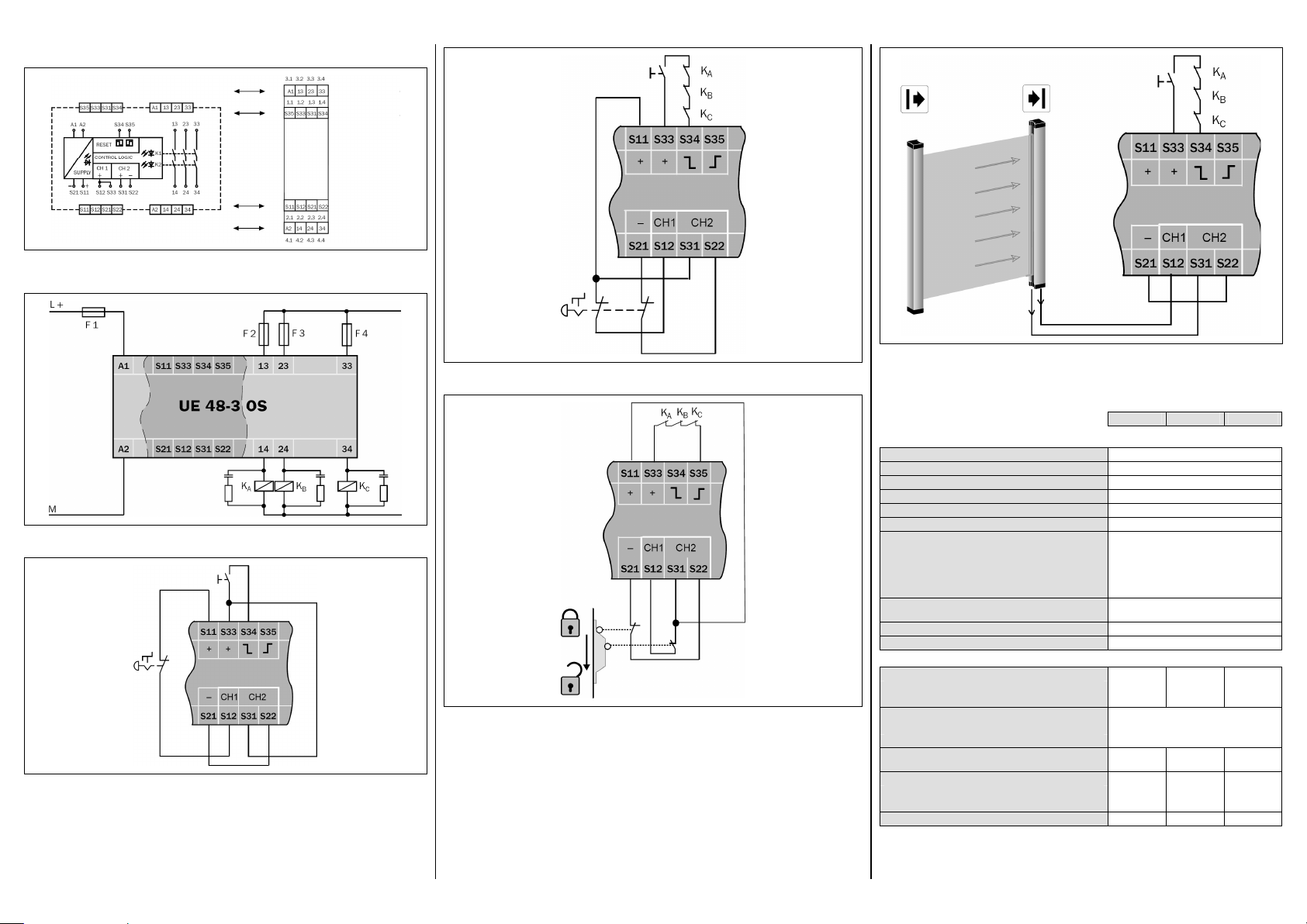
11 Schaltbild
Steckblockklemme
Gerätean
schluss
Steckblockklemme
Geräteanschluss
Steckblockklemme
Geräteanschluss
Steckblockklemme
Geräteanschluss
Abb. 1: Schaltbild UE48-3OS
12 Applikationsbeispiele
Abb. 2: Basisbeschaltung UE48-3OS: Spannungsversorgung, zweikanaliger Ausgangskreis (siehe
Technische Daten)
Abb. 3: Beispiel eines einkanaligen Not-Aus mit manueller Rücksetzung
Abb. 4: Beispiel eines zweikanaligen Not-Aus mit Querschlussüberwachung, m anueller Rücksetzung,
Schützkontrolle
Abb. 5: Beispiel einer zweikanaligen Schutztürabsicherung mit Querschlussüberwachung und manueller
Rücksetzung
Abb. 6: Beispiel einer berührungslos wirkenden Schutzeinrichtung (BWS) mit aktiven Schaltausgängen (OSSD), manueller Rücksetzung, Schützkontrolle
13 Technische Daten
13.1 Datenblatt
Minimal Typisch Maximal
Allgemeine Systemdaten
Sicherheits-Integritätslevel
SIL-Anspruchsgrenze
Safe failure fraction (SFF) 90 % (EN 62 061)
Hardware-Fehlertoleranz (HFT) 1 (EN 62 061)
Kategorie Kategorie 4 (EN ISO 13 849)
Performance Level
B
-Wert (Relais)
10D
AC-15, 230 V, I = 1,5 A
DC-13, 24 V, I = 2,5 A
PFHD (mittlere Wahrscheinlichkeit eines Gefahr
bringenden Ausfalls pro Stunde)
TM (Gebrauchsdauer) 20 Jahre (EN ISO 13 849)
Stoppkategorie 0 (EN 60 204-1)
Versorgungsspannung (A1, A2)
Eingangsspannung (A1, A2)
AC-Betrieb 21,6 V 24 V 26,4 V
DC-Betrieb 20,4 V 24 V 26,4 V
Spannungsversorgung (A1, A2)
Ausgangsstrompfade > 25 V AC/60 V DC PELV
Ausgangsstrompfade ′ 25 V AC/60 V DC SELV oder PELV
Restwelligkeit bei DC-Betrieb
(innerhalb der Grenzen von UV)
Leistungsaufnahme
AC-Betrieb 5 VA
DC-Betrieb 2,6 W
Nennfrequenz bei AC-Betrieb 50 Hz 60 Hz
1)
1)
I = 0,75 A
I = 0,63 A
1)
SIL3 (IEC 61 508)
SILCL3 (EN 62 061)
PL e (EN ISO 13 849)
1,26 × 10⁶ Schaltspiele
5,9 × 10⁶ Schaltspiele
435 × 103 Schaltspiele
10 × 106 Schaltspiele
–8
2)
3 × 10
2,4 V
SS
1)
Der tatsächlich erreichte Performance Level hängt von der Applikation ab. Für detaillierte Informationen zur exakten
Auslegung Ihrer Maschine/Anlage setzen Sie sich bitte mit Ihrer zuständigen SICK-Niederlassung in Verbindung.
2)
Bei DC = 99 % und MTTFD = 100 a (gemäß EN ISO 13 849, Tab. K1 und Formel C.7) und 8760 Schaltspielen/a.
Page 3

Minimal Typisch Maximal
L/R = 40 ms
L/R = 0 ms
L/R = 40 ms
Kontaktabstand:
AC-15: 230 VDC-
13: 24 V
DC-1: 24 V
AC-1: 230 V
Steuerspannung S33/S11 und S21
Steuerspannung 17,4 V DC 22 V DC 26,4 V DC
Steuerstrom 40 mA 100 mA
Kurzschlussstrom zwischen S33/S11 und S21 300 mA
Sicherung Elektronische Sicherung
Ansprechzeit bei Querschluss 50 ms
Einschaltzeit nach Querschluss 50 ms
Galvanische Trennung zwischen
A1/A2 und S21, S11, S33
Nein
Eingangskreise (S12, S31, S22, S34, S35)
Eingangsspannung (S12 und S31)
HIGH 17,4 V DC 26,4 V DC
LOW –3V DC +5 V DC
Eingangsstrom S12 und S31/S22 40 mA 100 mA
Eingangsstrom S34/S35 5 mA 50 mA
Rücksetzzeit
Manuelle Rücksetzung (S34) 40 ms
Automatische Rücksetzung
(BWS: S33/S35; taktil: S12/S35)
80 ms
Betätigungszeit Rücksetztaste 50 ms
Mindestabschaltzeit/Mindesteinschaltzeit 7 ms
Zulässige Testpulszeit/Testhäufigkeit
1000 µs/
10 s-1
Leitungswiderstand am Eingangskreis 35 Ohm
Ausgangsstrompfade (13/14, 23/24, 33/34)
Rückfallverzögerungszeit (K1/K2) 25 ms
Mindestausschaltzeit 70 ms 130 ms
Kontaktwerkstoff und Oberfläche Ag Sn O2 + 2µ Au
Freigabestrompfade (Schließer), sicherheitsrelevant 3
Kontaktart Zwangsgeführt
Kontaktbelastbarkeit (siehe Diagramm)
Schaltspannung AC 10 V 230 V AC
Schaltspannung DC 10 V 300 V DC
Schaltstrom 10 mA 6 A
Summenstrom I
Für UL 508- und CSA-Anwendungen
sum
12 A
Schaltspannung AC 230 V
Schaltstrom 6 A
Summenstrom I
Gebrauchskategorie (EN 60 947-5-1)
sum
AC-15 Ue 230 V AC, Ie 4 A (360 Sch/h)
12 A
AC-15 Ue 230 V AC, Ie 3 A (3600 Sch/h)
DC-13 Ue 24 V DC, Ie 4 A (360 Sch/h)
DC-13 Ue 24 V DC, Ie 2,5 A (3600 Sch/h)
Kontaktabsicherung gG 6 A
Zulässige Schalthäufigkeit 3600/h
Lebensdauer mechanisch 107 Schaltspiele
Minimal Typisch Maximal
DC-Ausschaltvermögen Elektrische Lebensdauer
1,2 mm
tLB: Lichtbogen-
brenndauer
Schaltstrom (A)
tLB > 5 ms
tLB < 5 ms
tLB < 5 ms
Schaltspannung (V DC)
Schaltstrom (A)
Schaltspiele
Betriebsdaten
Berührungsschutz (EN 60 664-1, EN 60 947-1)
Bemessungsstoßspannung U
Überspannungskategorie II
(EN 60 664-1) 4 kV
Imp
Bemessungsspannnung 300 V AC
Störaussendung EN 61 000-6-4
Störfestigkeit EN 61 000-6-2
Prüfspannung U
Schutzart
50 Hz 2 kV
eff
Gehäuse IP40 (EN 60 529)
Klemmen IP20 (EN 60 529)
Montage Hutschiene (EN 60 715)
Betriebsumgebungstemperatur –25 °C +55 °C
Lagertemperatur –25 °C +75 °C
Leiterquerschnitte
Eindraht (1×) 0,14 mm² 2,5 mm²
Eindraht (2×, gleicher Querschnitt) 0,14 mm² 0,75 mm²
Feindrahtig mit Aderendhülsen (1×) 0,25 mm² 2,5 mm²
Feindrahtig mit Aderendhülsen (2×, gleicher
Querschnitt)
0,2 mm² 0,5 mm²
Zulässiges Anzugsdrehmoment 0,5 Nm 0,6 Nm
Für UL 508- und CSA-Anwendungen
Anschlussquerschnitt
AWG 26-14
(nur 60/75 °C-Kupferlitzen verwenden)
Anzugsdrehmoment 5–7 lb⋅in
Gewicht 210 g
13.2 Maßbilder
Abb. 7: Maßbild UE48-3OS mit Schraubklemmen (mm)
Abb. 8: Maßbild UE48-3OS mit Steckblockklemmen (mm)
Page 4

OPERATING INSTRUCTIONS
The tests must be carried out by qualified
the tests can be reproduced and retraced
Commissioning requires a thorough check
UE48-3OS
Safety relay
en
SICK AG • Erwin-Sick-Straße 1
D-79183 Waldkirch • www.sick.com
8010593/ZV47/2018-08-02 • REIPA/XX
Printed in Germany (2018-08) • All rights
reserved • Subject to change without notice
1 Scope
These operating instructions are only applicable to the UE48-3OS safety relays with the
following entry on the type label in the field
Operating Instructions: 8010593
You will find the device’s date of manufacture
on the type label in the field Date Code in the
format yywwxxxx (yy = year, ww = calender
week, xxxx = serial number).
These operating instructions are original
operating instructions.
2 On safety
This chapter deals with your own safety and
the safety of the equipment operators.
= Please read this chapter carefully before
working with the UE48-3OS or with the
machine protected by the UE48-3OS.
2.1 Qualified safety personnel
The UE48-3OS safety relay must only be
mounted, installed, commissioned and
checked by qualified safety personnel.
Qualified safety personnel are defined as
persons who …
• have undergone the appropriate technical
training and
• have been instructed by the responsible
machine operator in the operation of the
machine and the current valid safety
guidelines and
• have access to the operating instructions of
the UE48-3OS safety relay and have read
and familiarised themselves with them.
2.2 Applications of the device
The UE48-3OS safety relay can be used:
• in accordance with EN ISO 13 849 up to PL e
and category 4
• in accordance with EN 62 061 to SILCL3
• in accordance with IEC 61 508 up to SIL3
The actual performance level or SIL claim limit
achieved depends on the external circuit, the
design of the wiring, the selection of the
control switch and its placement on the
machine.
The UE48-3OS safety relay has been evaluated
to UL 508.
The related actuators on the machine or
system can be safely shut down using the
safety relay’s output signal switching contacts.
The UE48-3OS safety relay is used for:
• electro-sensitive protective equipment (ESPE)
with monitored active output signal switching
device (OSSD): single-channel, dual-channel (in
accordance with EN 61 496-1), e.g. with the
following SICK devices: C2000, M2000, C4000,
M4000, S3000, S300
• emergency stop pushbuttons (EN ISO 13 850):
single- or dual-channel, e.g. SICK ES21
• safety interlocks (EN 1088): single- or dualchannel, e.g. safety doors
• safety circuits in accordance with EN 60 204-1,
e.g. for moving covers
• and is suitable for connecting downstream of a
pressure mat as per EN 13 856, normally open,
in four-wire technology
2.3 Correct use
The UE48-3OS safety relay must be used only as
defined in section 2.2 “Applications of the device”.
It must be used only by qualified safety personnel
and only on the machine where it has been installed and initialised by qualified safety personnel
in accordance with the operating instructions. If
the device is used for any other purposes or modified in any way — also during mounting and installation — any warranty claim against SICK AG shall
become void.
2.4 General safety notes and protective
measures
Pay attention to the safety notes and
protective measures!
Please observe the following items in order
to ensure the correct use of the UE48-3OS
safety relay.
• During the mounting, installation and
usage of the safety relay, observe the
standards and directives applicable in
your country.
• The national/international rules and
regulations apply to the installation,
commissioning, use and periodic
technical inspection of the safety relay,
in particular:
– Machinery Directive
– Work Equipment Directive
– EMC directive
– the work safety regulations and safety
rules
• Manufacturers and operators of the machine on which a safety relay is used are
responsible for obtaining and observing
all applicable safety regulations and
rules.
•
safety personnel or specially qualified
and authorised personnel and must be
recorded and documented to ensure that
at any time by third parties.
• The operating instructions must be made
available to the operator of the machine
where the UE48-3OS safety relay is used.
• The machine operator is to be instructed
in the use of the device by qualified
safety personnel and must be instructed
to read the operating instructions.
3 Product description
3.1 Structure and operating principle
of the device
The inputs on the UE48-3OS safety relay are
prepared for the connection of the control
switches or safety sensors listed in section 2.2
“Applications of the device”. The three enable
current paths are designed as safe outputs.
3.2 Device functions
The actuation of the sensor or the entry into the
ESPE’s protective field results in the opening of
the enable current paths. Manual or automatic
reset as well as external device monitoring are to
be implemented using external wiring as required
(see 5.4 “Reset” and 5.5 “External device
monitoring”).
In order to attain SIL3/PL e, connect the
external device monitoring!
In order to reach SIL3/PL e, an external
diagnosis with DC ≥ 99 % must be applied
(i.e. the external device monitoring must be
connected).
Please also read the notes in chapter 12
“Application examples”.
3.3 Status indicators
Display Meaning
SUPPLY Ν Green Supply voltage active
K1 Ν Green Channel 1 switched
K2 Ν Green Channel 2 switched
4 Mounting
Mounting only with enclosure rating IP54
or better!
The safety relay is only allowed to be mounted in the control cabinet. The control cabinet must at least comply with enclosure
rating IP54.
= Mounting in accordance with EN 50 274.
= The modules are located in a 22.5 mm wide
modular system for 35 mm mounting rails as
per EN 60 715.
5 Electrical installation
Note:
All external switching elements and their wiring
must withstand an ampacity, maximal short-circuit
load of I
= 1000 A (according to EN 60 947-5-1).
max
Switch the entire machine/system off
line!
• The voltage supply must satisfy the regulations
for extra-low voltages with safe isolation (SELV,
PELV) for overvoltage category II as per
EN 60 664 and EN 50 178.
Note:
The basic insulation of the components connected
to the safety relay must match the highest voltage
connected to the safety relay.
All circuits (and if necessary other EDM) must then
also be designed for the highest voltage level.
• All connections, wiring and cable runs must
comply with the required category as per
EN ISO 13 849 und EN 62 061 (e.g. cables laid
with protection, individually sheathed cable with
screen etc.).
• To protect the contact outputs on the UE48-3OS
and to increase the service life, the loads
connected must be equipped with, e.g., varistors
and RC circuits. Please also note that the selection of the arc suppression can increase the
total response time of the safety function. For
installation in environments of overvoltage
category III, external protection elements must
be used.
• The output signal switching devices and the
external device monitoring (EDM) must be wired
in the control cabinet.
• To prevent the welding of the contacts on the
built-in relay, an overcurrent protection device
with short-circuit protection (duty class gG) in
accordance with the related usage category is to
be selected and integrated into the enable
current paths (see Fig. 2, fuse F2/F3/F4).
5.1 Pin assignments
Terminal Description
A1 Voltage supply (+24 V DC)
A2 Voltage supply (0 V DC)
S11 + Control voltage
S21 0 V control voltage
S12 + Input circuit 1 (K1)
S31 + Input circuit 2 (K2)
S22 – Input circuit 2 (K2)
S33 For reset circuit (complies S12)
S33–S34 Manual Reset
S33–S35 Automatic reset
13–14 Enable current path 1
23–24 Enable current path 2
33–34 Enable current path 3
5.2 Operating modes: ESPE
Single-channel operation
The output signal switching device on the ESPE is
connected to terminal S12. Wire jumpers are to be
connected between S21 and S22 as well as
between S31 and S33.
Dual-channel operation
One output signal switching device on the ESPE is
to be connected to S12, the second output signal
switching device to S31. S21–S22 are to be
connected using a wire jumper.
5.3 Operating modes: tactile sensors
Single-channel operation
The volt-free switching element on the safety
sensor is connected between S11 and S12. Wire
jumpers are to be connected between S33 and
S31 as well as between S21 and S22. (see Fig. 3).
Dual-channel operation
The two volt-free switching elements on the safety
sensor are to be connected between S11 and S12
or S21 and S22. A wire jumper is to be connected
between S11 and S31 (see Fig. 4 and Fig. 5).
5.4 Reset
Manual reset
The reset button (N/O contact) must be wired
between the terminals S33 and S34. The reset
button is to be installed outside the hazardous
area such that it cannot be pressed from inside
the hazardous area. When operating the reset
button, the operator must have full visual
command of the hazardous area. The reset is
monitored. For emergency switching off
applications, a manual reset is to be used.
Automatic reset
A wire jumper is to be connected between S33 and
S35.
5.5 External device monitoring
The external device monitoring for the actuators
integrated is only effective on reset. The connection of the N/C contacts for the contact elements
operated in series with the reset circuit provides
this external device monitoring.
6 Commissioning and regular
tests
by qualified safety personnel!
Before you operate a system protected by
the safety relay for the first time, make sure
that the system is first checked and
released by qualified safety personnel.
= Please read the notes in chapter 2 “On
safety”.
= Observe the relevant laws and national
regulations.
Check the hazardous area!
= Ensure there is nobody in the hazardous
area before commissioning.
= Secure the hazardous area against entry.
Regular inspection of the protective devices by
qualified safety personnel
= Check the system following the inspection
intervals specified in the national rules and
regulations.
– Each safety application must be checked at
an interval specified by you.
– The effectiveness of the protective devices
must be checked daily by a specialist or by
authorised personnel.
= If changes have been made to the machine or
the protective device, or the safety relay has
been changed or repaired, you must again
thoroughly check the entire safety application.
7 In the event of faults or
errors
Cease operation if the cause of the
malfunction has not been clearly
identified!
= Stop the machine if you cannot clearly
identify or allocate the error and if you
cannot safely rectify the malfunction.
Complete function test after rectification
of fault!
= After rectifying a fault, perform a
complete function test.
8 Disposal
Always dispose of serviceableness devices
in compliance with local/national rules and
regulations with respect to waste disposal.
9 Ordering information
Part Part number
UE48-3OS for 24 V AC/DC
with screw type terminals
UE48-3OS for 24 V AC/DC
with removable terminals
(type code)
6025089
(UE48-3OS2D2)
6025097
(UE48-3OS3D2)
10 Compliance with EU
directives
UE48-3OS, Safety relay
SICK AG, Erwin-Sick-Straße 1, D-79183
Waldkirch
You can call up the EU declaration of confor-
mity and the current operating instructions by
entering the part number in the search field at
www.sick.com (part number: see the type label
entry in the “Ident. no.” field).
Direct link to EU declaration of conformity:
www.sick.com/9091706
The undersigned, representing the manufacturer, herewith declares that the product is in
conformity with the provisions of the following
EU directive(s) (including all applicable amendments), and that the standards and/or technical specifications stated in the EU declaration
of conformity have been used as a basis for
this.
• MACHINERY DIRECTIVE 2006/42/EC
• EMC DIRECTIVE 2014/30/EU
• ROHS DIRECTIVE 2011/65/EU
Waldkirch: 2018-07-10
ppa. Walter Reithofer
Vice President R&D
(GBC Industrial Safety)
authorized for technical
documentation
Notified body: No. 0340, DGUV Test, Prüf- und
Zertifizierungsstelle Elektrotechnik, GustavHeinemann-Ufer 130, 50968 Köln
EC type-examination: ET 16022
ppa. Birgit Knobloch
Vice President
Operations
(GBC Industrial
Safety)
Page 5

11 Internal circuitry
Removable terminal
Device connection
Removable terminal
Device connection
Removable terminal
Device connection
Removable terminal
Device connection
Fig. 1: Internal circuitry UE48-3OS
12 Application examples
Fig. 2: Basic circuit UE48-3OS: voltage supply, dual-channel output circuit (see technical
specifications)
Fig. 3: Example of single-channel emergency switching off with manual reset
Fig. 4: Example of dual-channel emergency switching off with cross-circuit monitoring, manual reset,
external device monitoring
Fig. 5: Example of dual-channel guard protection with cross-circuit monitoring and manual reset
Fig. 6: Example of an electrosensitive protective device (ESPE) with active output signal switching
devices (OSSD), manual reset, external device monitoring
13 Technical specifications
13.1 Data sheet
Minimum Typical Maximum
General system data
Safety integrity level
SIL claim limit
Safe failure fraction (SFF) 90 % (EN 62 061)
Hardware fault tolerance (HFT) 1 (EN 62 061)
Category Category 4 (EN ISO 13 849)
Performance Level
B
value (relay)
10D
AC-15, 230 V, I = 1.5 A
DC-13, 24 V, I = 2.5 A
PFHD (mean probability of a dangerous failure per
2)
hour)
TM (mission time) 20 years (EN ISO 13 849)
Stop category 0 (EN 60 204-1)
Supply voltage (A1, A2)
Input voltage (A1, A2)
AC operation 21.6 V 24 V 26.4 V
DC operation 20.4 V 24 V 26.4 V
Voltage supply (A1, A2)
Output current circuits > 25 V AC/60 V DC PELV
Output current circuits ′ 25 V AC/60 V DC SELV or PELV
Residual ripple with DC operation
(within the limits of VS)
Power consumption
AC operation 5 VA
DC operation 2.6 W
Nominal frequency for AC operation 50 Hz 60 Hz
1)
The Performance Level actually attained depends on the application. For detailed information on the exact design of
your machine/system, please contact your local SICK representative.
2)
With DC = 99 % and MTTFD = 100 a (according to EN ISO 13 849, Tab. K1 and formula C.7) and 8760 switching
operations/a.
1)
I = 0.75 A
I = 0.63 A
1)
SIL3 (IEC 61 508)
SILCL3 (EN 62 061)
1)
PL e (EN ISO 13 849)
1.26 × 10⁶ switching operations
5.9 × 10⁶ switching operations
435 × 103 switching operations
10 × 106 switching operations
–8
3 × 10
2.4 V
SS
Page 6

Minimum Typical Maximum
L/R = 40 ms
L/R = 0 ms
L/R = 40 ms
Contact
AC-15: 230 V
DC-13: 24 V
DC-1: 24 V
AC-1: 230 V
Control voltage S33/S11 and S21
Control voltage 17.4 V DC 22 V DC 26.4 V DC
Control current 40 mA 100 mA
Short-circuit current between S33/S11 and S21 300 mA
Fuse Electronic fuse
Response time in case of cross-circuit 50 ms
Switch on time after cross-circuit 50 ms
Electrical isolation between A1/A2 and S21, S11, S33 No
Input circuits (S12, S31, S22, S34, S35)
Input voltage (S12 and S31)
HIGH 17.4 V DC 26.4 V DC
LOW –3V DC +5 V DC
Input current S12 and S31 40 mA 100 mA
Input current S34/S35 5 mA 50 mA
Reset time
Manual reset (S34) 40 ms
Automatic reset
(ESPE: S33/S35; tactile: S12/S35)
80 ms
Reset button operation time 50 ms
Minimum shutdown time/minimum switch-on time 7 ms
Permissible test pulse duration/test frequency
1000 µs/
10 s-1
Cable resistance on the input circuit 35 Ohm
Output current circuits (13/14, 23/24, 33/34)
Reactivation delay (K1/K2) 25 ms
Minimum switch off time 70 ms 130 ms
Contact material and surface finish Ag Sn O2 + 2µ Au
Enable current paths (normally open contact), safety
relevant
3
Contact type Positively guided
Max. contact load (see diagram)
Switching voltage AC 10 V 230 V
Switching voltage DC 10 V 300 V
Switching current 10 mA 6 A
Total current I
For UL 508 and CSA applications
sum
12 A
Switching voltage AC 230 V
Switching current 6 A
Total current I
Usage category (EN 60 947-5-1)
sum
AC-15 Ue 230 V AC, Ie 4 A (360 switching
operations/h)
AC-15 Ue 230 V AC, Ie 3 A (3600
switching operations/h)
DC-13 Ue 24 V DC, Ie 4 A (360 switching
operations/h)
DC-13 Ue 24 V DC, Ie 2.5 A (3600
switching operations/h)
12 A
Contact fuse protection gG 6 A
Permissible switching frequency 3600/h
Service life, mechanical 107 switching operations
Minimum Typical Maximum
DC contact current-breaking capacity Service life, electrical
clearance:
1.2 mm
tLB: Arc duration
tLB > 5 ms
Switching current (A)
tLB < 5 ms
Switching voltage (V DC)
tLB < 5 ms
Switching current (A)
Switching operations
Operating data
Protection against physical contact (EN 60 664-1,
EN 60 947-1)
Rated impulse voltage V
Overvoltage category II
(EN 60 664-1) 4 kV
Imp
Rated voltage 300 V AC
Radiated emissions EN 61 000-6-4
Interference resistance EN 61 000-6-2
Test voltage U
Enclosure rating
50 Hz 2 kV
rms
Housing IP40 (EN 60 529)
Terminals IP20 (EN 60 529)
Mounting Mounting rail (EN 60 715)
Ambient operating temperature –25 °C +55 °C
Storage temperature –25 °C +75 °C
Wire cross-sections
Single wire (1×) 0.14 mm² 2.5 mm²
Single wire (2×, same cross-section) 0.14 mm² 0.75 mm²
Fine stranded wire with ferrules (1×) 0.25 mm² 2.5 mm²
Fine stranded wire with ferrules (2×, same cross-
section)
0.2 mm² 0.5 mm²
Allowed tightening torque 0.5 Nm 0.6 Nm
For UL 508 and CSA applications
Connection cross-section
AWG 26-14
(only use 60/75 °C copper flexible wire)
Tightening torque 5-7 lb⋅in
Weight 210 g
13.2 Dimensional drawings
Fig. 7: Dimensional drawing UE48-3OS with screw type terminals (mm)
Fig. 8: Dimensional drawing UE48-3OS with removable terminals (mm)
 Loading...