

SICK Flexi Classic series, UE410-GU, UE410-MU, UE410-8DI, UE410-XU Operating Instructions Manual
...Page 1
Flexi Classic
Modular Safety Controller
OPERATING INSTRUCTIONS
en
Page 2

Operating instructions
Flexi Classic
This document is protected by the law of copyright, whereby all right s established therein remain with the
company SICK AG. Reproduction of this document or parts of this document is only permissible within the limits
of the legal det ermination of Copyright Law. Alteration or abridgement of the document is not permitted without
the explicit written approval of the company SICK AG.
2 © SICK AG • Industrial Safety Systems • Germany • All rights reserved 8011509/YPP0/2015-10-26
Subject to change without notice
Page 3

Operating instructions
Flexi Classic
Contents
Contents
1 About this document.................................................................................................... 6
1.1 Function of this document................................................................................6
1.2 Target group .....................................................................................................6
1.3 Information depth.............................................................................................6
1.4 Scope................................................................................................................7
1.5 Abbreviations....................................................................................................7
1.6 Symbols used ................................................................................................... 7
2 On safety.....................................................................................................................11
2.1 Qualified safety personnel..............................................................................11
2.2 Applications of the device...............................................................................11
2.3 Correct use .....................................................................................................12
2.4 General safety notes and protective measures..............................................12
2.5 Environmental protection ...............................................................................14
2.5.1 Disposal.........................................................................................14
2.5.2 Separation of materials.................................................................14
3 Product description....................................................................................................15
3.1 Special features..............................................................................................15
3.2 Structure.........................................................................................................16
3.2.1 UE410-MU main module...............................................................16
3.2.2 UE410-GU main module................................................................17
3.2.3 UE410-8DI input extension module ..............................................18
3.2.4 UE410-XU input/output extension ................................................18
3.2.5 UE410-2RO/UE410-4RO output modules.....................................18
3.2.6 Gateways.......................................................................................18
3.2.7 Module overview, adjustments and facilities for connecting
sensors..........................................................................................19
3.3 UE410-MU main module ................................................................................22
3.3.1 Controls and status indicators ......................................................24
3.3.2 Terminal assignment.....................................................................25
3.3.3 Outputs..........................................................................................26
3.4 UE410-GU main module.................................................................................27
3.4.1 Controls and status indicators ......................................................28
3.4.2 Terminal assignment.....................................................................29
3.4.3 Global emergency stop with the UE410-GU ..................................29
3.4.4 Local emergency stop on the UE410-GU.......................................31
3.4.5 Inputs............................................................................................32
3.4.6 Outputs..........................................................................................32
3.4.7 Connection of a UE410-8DI...........................................................33
3.4.8 Power-up delay and response time of the UE410-GU ...................33
3.4.9 Diagnostics and troubleshooting for the UE410-GU......................33
3.5 UE410-XU module ..........................................................................................35
3.5.1 Controls and status indicators ......................................................35
3.6 UE410-MU/UE410-XU programs....................................................................36
3.6.1 Program 1......................................................................................37
3.6.2 Program 2......................................................................................38
3.6.3 Programs 3.1 and 3.2 ...................................................................39
3.6.4 Program 4......................................................................................40
3.6.5 Programs 5.1 and 5.2 ...................................................................41
3.6.6 Program 6......................................................................................42
8011509/YPP0/2015-10-26 © SICK AG • Industrial Safety Systems • Germany • All rights reserved 3
Subject to change without notice
Page 4

Contents
3.6.7 Program 7..................................................................................... 43
3.6.8 Program 8..................................................................................... 44
3.6.9 Program 9..................................................................................... 45
3.6.10 Connection of sensors to the UE410-MU/UE410-XU.................... 46
3.7 UE410-GU programs...................................................................................... 49
3.8 UE410-8DI input extension module............................................................... 51
3.8.1 AND link........................................................................................ 52
3.8.2 OR link.......................................................................................... 53
3.8.3 Bypass .......................................................................................... 53
3.8.4 Reciprocal assignment — Mirror mode ......................................... 54
3.8.5 Connection of sensors to the UE410-8DI ..................................... 54
3.8.6 Controls and status indicators...................................................... 56
3.8.7 Inputs and outputs ....................................................................... 57
3.9 UE410-2RO/UE410-4RO output modules ..................................................... 57
3.9.1 Output module UE410-2RO.......................................................... 57
3.9.2 Output module UE410-4RO.......................................................... 58
3.9.3 Controls and status indicators...................................................... 59
3.9.4 UE410-2RO inputs and outputs.................................................... 59
3.9.5 UE410-4RO inputs and outputs.................................................... 59
Operating instructions
Flexi Classic
4 Special applications and functions........................................................................... 60
4.1 RE300 magnetic safety switch....................................................................... 61
4.2 IN4000 inductive safety switch...................................................................... 62
4.3 Testable single-beam photoelectric safety switches...................................... 63
4.4 Two-hand operation/jog mode....................................................................... 66
4.5 OR function.................................................................................................... 67
4.6 Muting function.............................................................................................. 68
4.6.1 Muting with two sensors............................................................... 69
4.6.2 Muting cycle..................................................................................69
4.6.3 Muting sensors............................................................................. 69
4.7 Placement of muting sensors ........................................................................ 70
4.7.1 Muting with two sensors (a sensor pair), crossed placement....... 71
4.7.2 4-sensor muting, sequential layout .............................................. 72
4.7.3 Muting with UE410-MU/UE410-XU............................................... 72
4.8 SICK muting sensors...................................................................................... 73
4.9 Bypass............................................................................................................ 74
4.10 Connecting S1, S2, S3................................................................................... 75
4.10.1 Operation with restart interlock.................................................... 75
4.10.2 Operation without restart interlock............................................... 75
4.10.3 Operation with external device monitoring (EDM) ........................ 75
4.11 Retriggering of the delayed OSSDs................................................................ 76
4.12 Grouping of subsystems ................................................................................ 78
4.13 ENABLE input................................................................................................. 79
5 Mounting/dismantling .............................................................................................. 80
5.1 Steps for mounting the modules.................................................................... 80
5.2 Steps for dismantling the modules................................................................ 81
5.3 Removing the anti-manipulation cover .......................................................... 82
6 Electrical installation................................................................................................ 83
4 © SICK AG • Industrial Safety Systems • Germany • All rights reserved 8011509/YPP0/2015-10-26
Subject to change without notice
Page 5

Operating instructions
Flexi Classic
Contents
7 Application examples and connection diagrams......................................................85
7.1 L21 on the UE410-MU/XU..............................................................................85
7.2 Emergency stop on the UE410-MU/XU...........................................................85
7.3 RE300 on the UE410-MU/XU.........................................................................86
7.4 Two-hand IIIC on the UE410-MU/XU...............................................................86
7.5 C2000 and emergency stop on the UE410-MU/XU, two hazardous
areas...............................................................................................................87
7.6 i11 on the UE410-MU/XU, two independent hazardous areas.......................87
7.7 IN4000 on the UE410-MU/XU........................................................................88
7.8 C4000 on the UE410-MU/XU, 2-sensor muting.............................................88
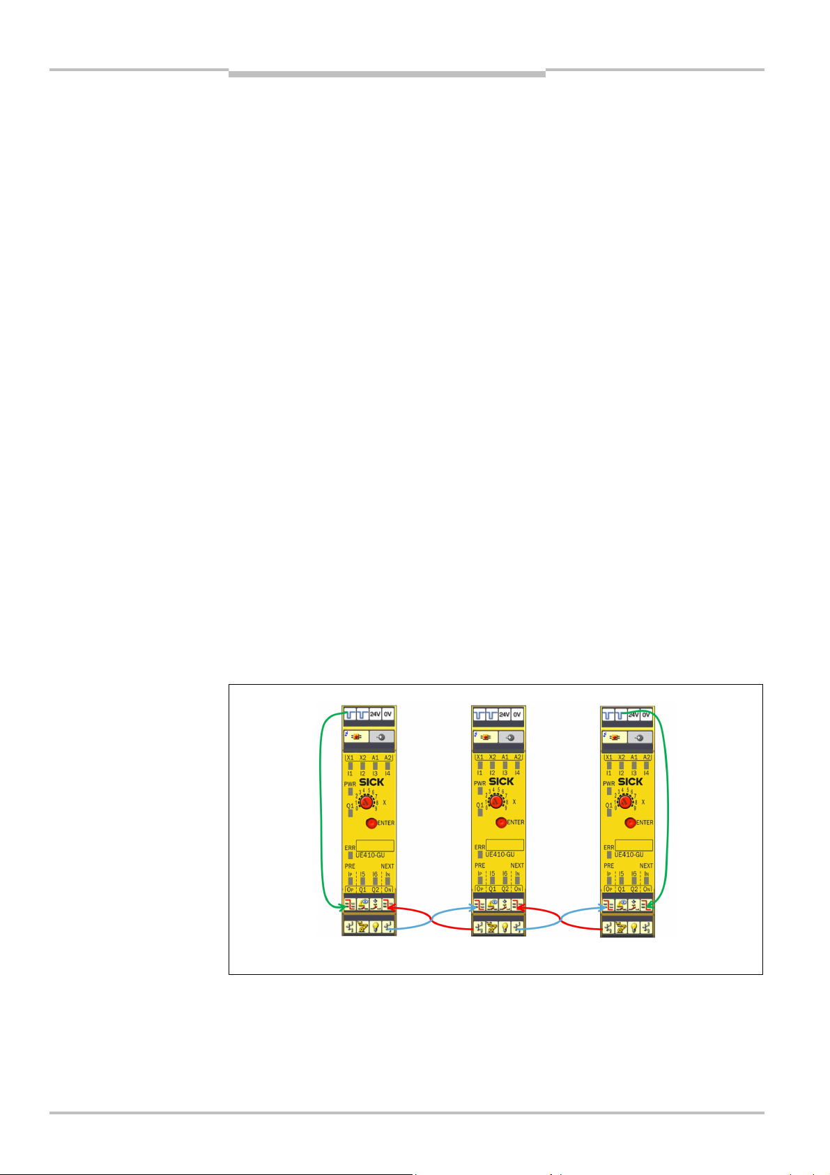
7.9 Global emergency stop with two UE410-GU...................................................89
8 Commissioning...........................................................................................................90
8.1 Validation of the application...........................................................................90
8.2 Test notes.......................................................................................................91
8.2.1 Tests before the first commissioning ............................................91
8.2.2 Regular testing..............................................................................91
8.2.3 Regular inspection of the protective device by qualified
safety personnel............................................................................91
9 Configuration..............................................................................................................92
9.1 Accepting the system configuration................................................................92
10 Diagnostics.................................................................................................................93
10.1 In the event of faults or errors........................................................................93
10.2 Replacement of a module ..............................................................................93
10.3 SICK support...................................................................................................94
10.4 Error indications of the ERR error LED............................................................94
10.5 Anti-manipulation measures...........................................................................95
11 Technical specifications ............................................................................................96
11.1 Data sheet......................................................................................................96
11.1.1 UE410-MU/UE410-XU modules ....................................................96
11.1.2 UE410-GU module...................................................................... 101
11.1.3 UE410-8DI input extension module ........................................... 105
11.1.4 UE410-2RO/UE410-4RO output modules.................................. 107
11.2 Dimensional drawings................................................................................. 111
11.2.1 UE410-MU and UE410-GU main modules.................................. 111
11.2.2 UE410-XU, UE410-8DI, UE410-2RO, UE410-4RO, UE410-
PRO, UE410-DEV, UE410-CAN modules..................................... 111
12 Ordering information............................................................................................... 112
12.1 Available modules ....................................................................................... 112
12.2 Accessories/spare parts.............................................................................. 115
12.2.1 Single-beam photoelectric safety switches ................................ 115
12.2.2 Non-contact safety switches....................................................... 116
12.2.3 Safety light curtains and multiple light beam safety devices ..... 117
12.2.4 Safety laser scanners and safety camera system...................... 117
12.2.5 Muting lamps and cables........................................................... 117
12.2.6 Anti-manipulation cover.............................................................. 117
13 Annex....................................................................................................................... 118
13.1 Compliance with EU directives..................................................................... 118
13.2 Manufacturer’s checklist............................................................................. 118
13.3 List of tables................................................................................................ 119
13.4 List of illustrations....................................................................................... 120
8011509/YPP0/2015-10-26 © SICK AG • Industrial Safety Systems • Germany • All rights reserved 5
Subject to change without notice
Page 6

Chapter 1 Operating instructions
About this document
Flexi Classic
1 About this document
Please read this chapter carefully before working with this documentation and the Flexi
Classic modular safety controller.
1.1 Function of this document
These operating instructions are designed to address the technical personnel of the machine manufacturer or the machine operator in regards to safe mounting, configuration,
electrical installation, commissioning, operation and maintenance of the Flexi Classic
modular safety controller.
These operating instructions do not provide instructions for operating machines on which
the safety controller is, or will be, integrated. Information on this is to be found in the appropriate operating instructions for the machine.
1.2 Target group
These operating instructions are addressed to planning engineers, machine designers and
operators of plants and systems which are to be protected by a Flexi Classic modular safe-
ty controller. They are also addressed to people who integrate the Flexi Classic modular
safety controller into a machine, initialise its use, or who are in charge of servicing and
maintaining the device.
Note
1.3 Information depth
These operating instructions contain the following information on the Flexi Classic modular
safety controller:
• mounting
• electrical installation
• commissioning and configuration
• care and maintenance
Planning and using SICK protective devices also require specific technical skills which are
not detailed in this documentation.
When operating the Flexi Classic modular safety controller, the national, local and statutory rules and regulations must be observed.
General information on accident prevention using opto-electronic protective devices can
be found in the competence brochure “Guidelines Safe Machinery”.
We also refer you to the homepage on the Internet at www.sens-control.com.
Here you will find information on:
• product and application animations
• configuration aid
• these operating instructions in different languages for viewing and printing
• fault, error diagnosis and
troubleshooting
• part numbers
• conformity and approval
6 © SICK AG • Industrial Safety Systems • Germany • All rights reserved 8011509/YPP0/2015-10-26
Subject to change without notice
Page 7

Operating instructions Chapter 1
Flexi Classic
About this document
1.4 Scope
These operating instructions are original operating instructions.
These operating instructions apply to all Flexi Classic safety controller modules with the
following entry in the field Operating Instructions on the type label: “E-01” or higher. Take
into account the respectively applicable operating instructions (refer to the type label entry
on the modules).
1.5 Abbreviations
EDM
ESPE
OSSD
PLC
SIL
SILCL
Note
Ν, ∏, ν
= Take action …
WARNING
External device monitoring
Electro-sensitive protective equipment (e.g. C4000)
Output signal switching device
Programmable logic controller
Safety Integrity Level
SIL claim limit
1.6 Symbols used
Refer to notes for special features of the device.
LED symbols describe the state of a diagnostics LED. Examples:
Ν The LED is illuminated constantly.
∏ The LED is flashing.
ν The LED is off.
Instructions for taking action are shown by an arrow. Read carefully and follow the
instructions for action.
Warning!
A warning notice indicates an actual or potential risk or health hazard. They are designed
to help you to prevent accidents.
Read carefully and follow the warning notices!
8011509/YPP0/2015-10-26 © SICK AG • Industrial Safety Systems • Germany • All rights reserved 7
Subject to change without notice
Page 8
Chapter 1 Operating instructions
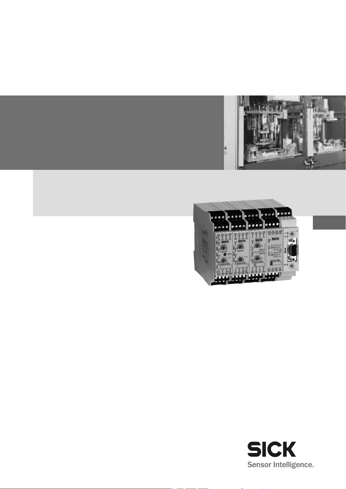
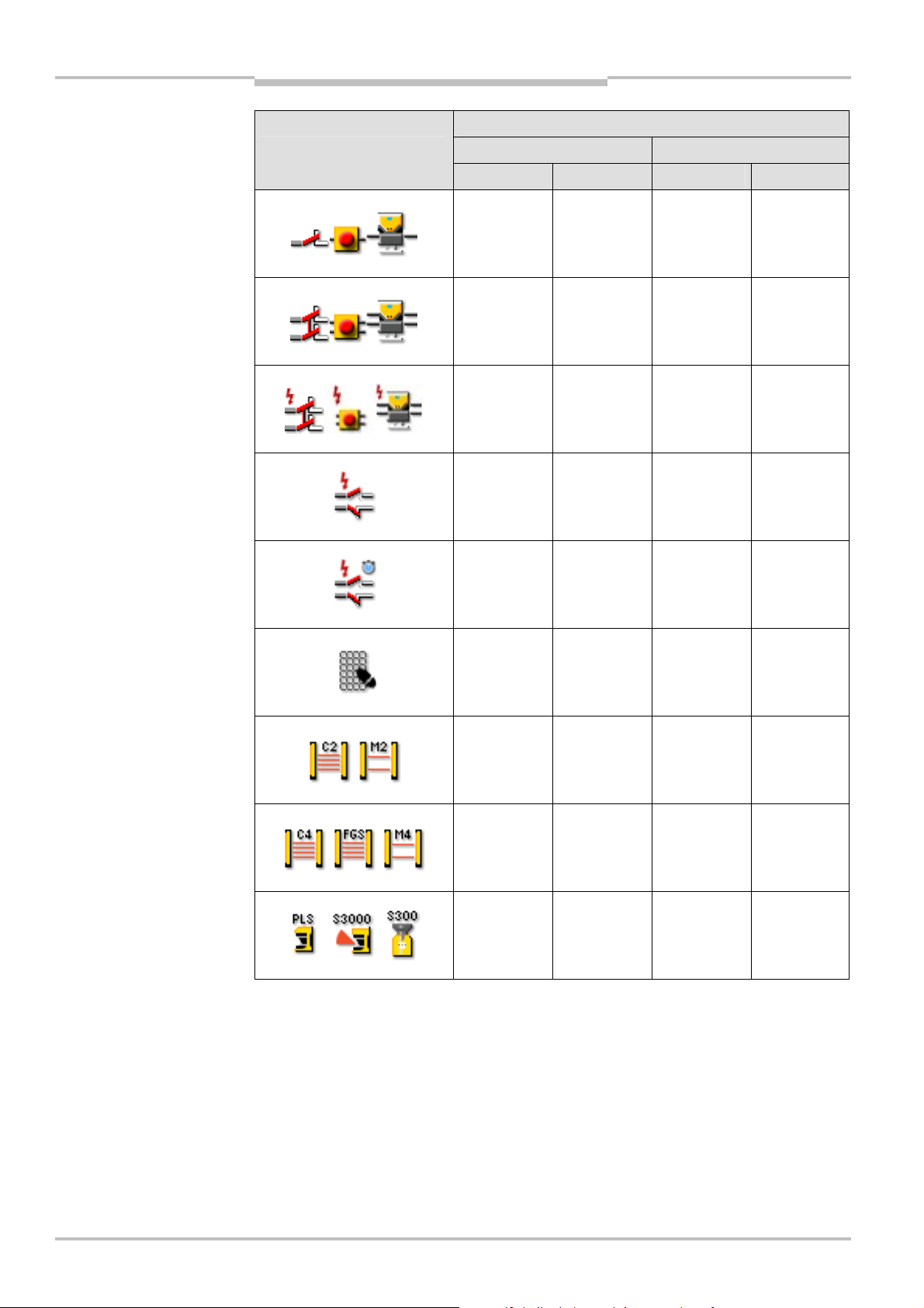
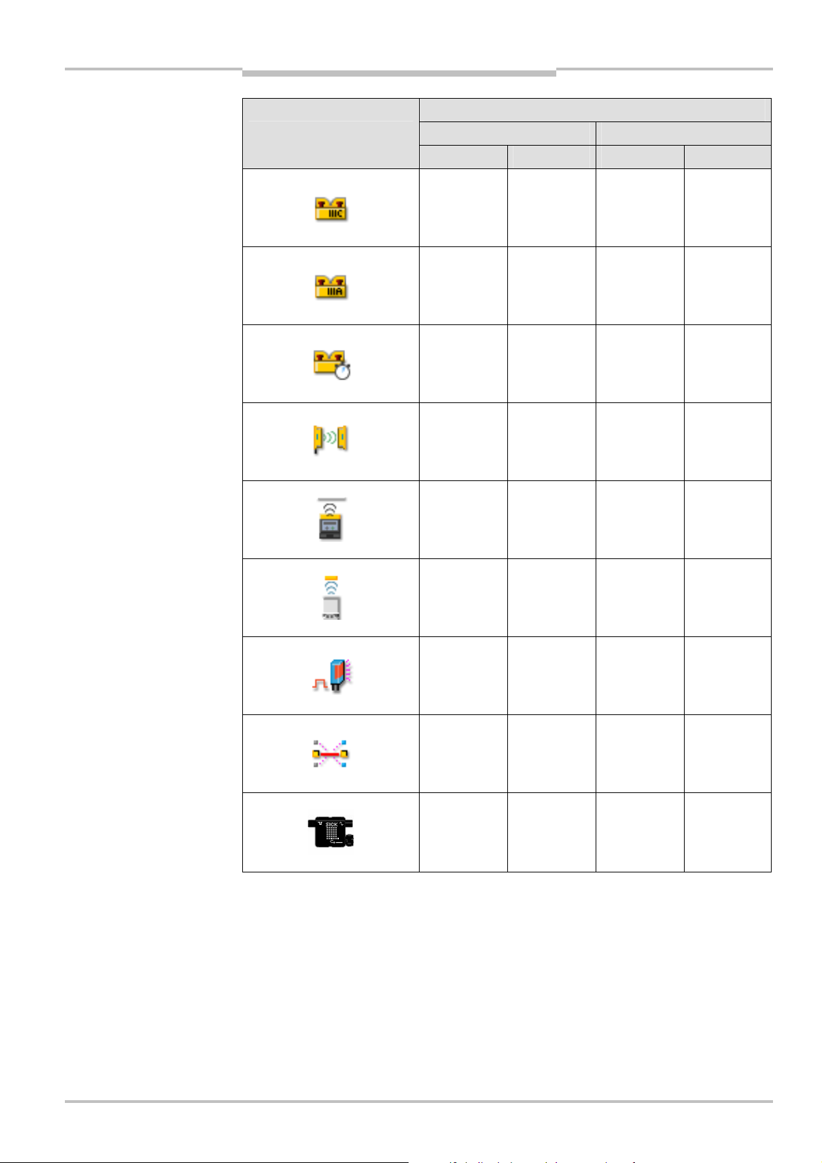
Tab.1:
Sensor symbols
About this document
Flexi Classic
Symbol Sensors
Electro-mechanical safety switches
Emergency stop button
Electro-sensitive protective equipment (ESPE)
Sensors that can be tested (e.g. photoelectric switches)
Inductive safety sensors (e.g. IN4000)
Two-hand operating panel (IIIA)
Two-hand operating panel (IIIC)
Jog mode via two-hand operating panel (IIIA) (time limit 5 s)
Muting lamp and Reset required lamp (not monitored)
Lamp permanently ON: Muting active
Lamp flashing 1 Hz: Reset required
Pressure sensitive mats (4-wire system)
Reset button
8 © SICK AG • Industrial Safety Systems • Germany • All rights reserved 8011509/YPP0/2015-10-26
Flexi Loop
Subject to change without notice
Page 9
Operating instructions Chapter 1
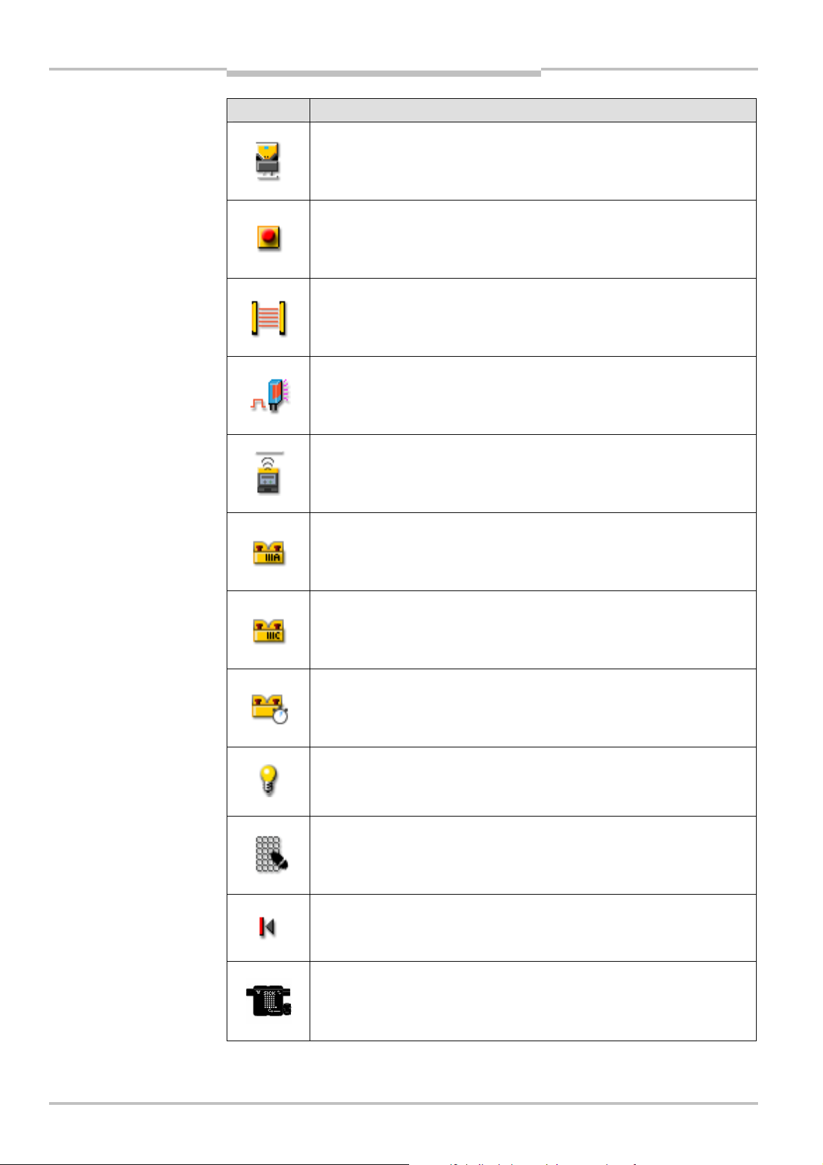
Tab.2:
Module function
Flexi Classic
About this document
symbols
Symbol Module functions
Bypass function with electro-mechanical dual-channel equivalent switch
(e.g. enabling switch),
Bypass function limited to 60 s
Muting station with two inputs for muting sensors
Retriggering
Monitored semiconductor output
Off delay
ENABLE (EN)
8011509/YPP0/2015-10-26 © SICK AG • Industrial Safety Systems • Germany • All rights reserved 9
Subject to change without notice
Page 10
Chapter 1 Operating instructions
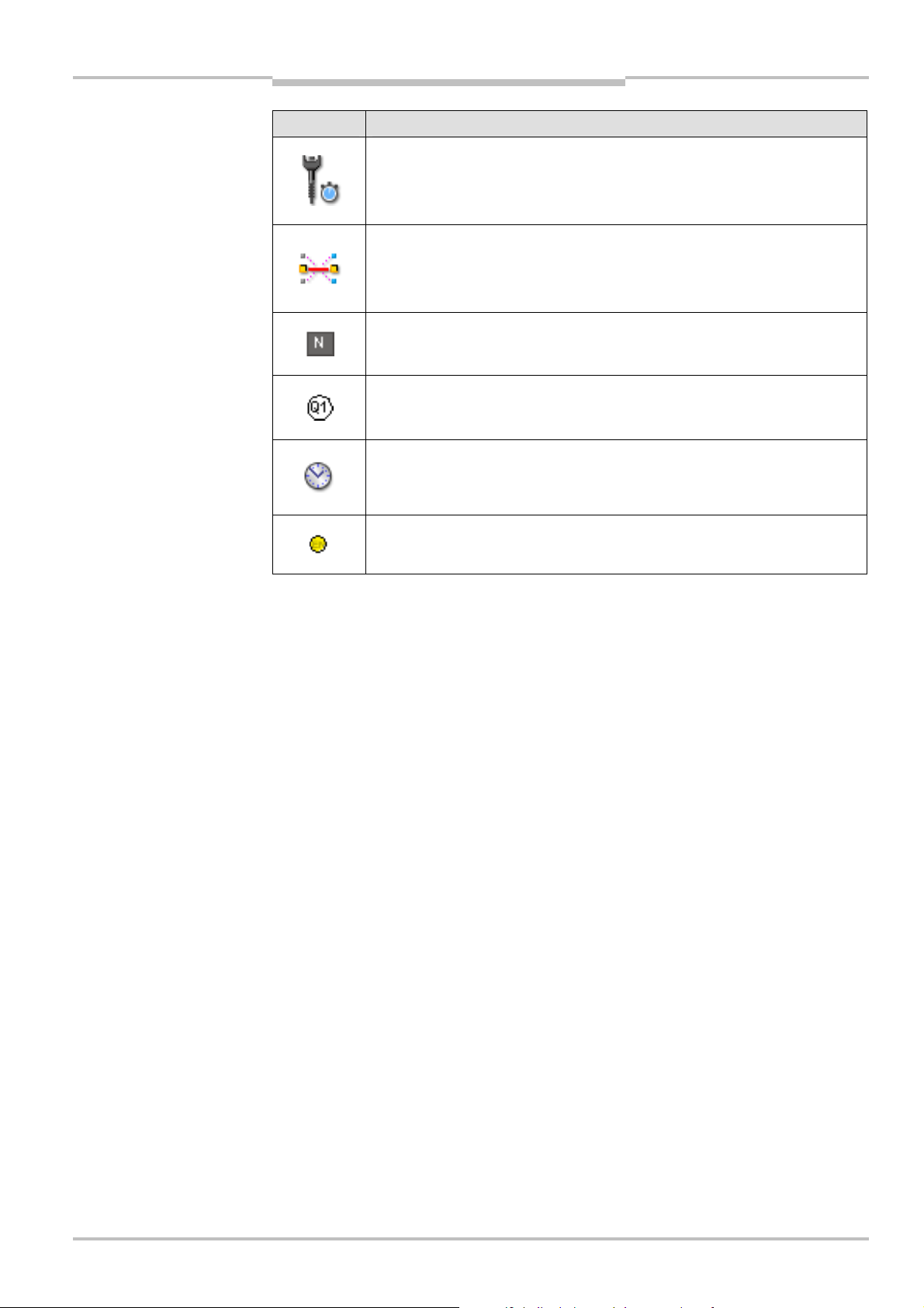
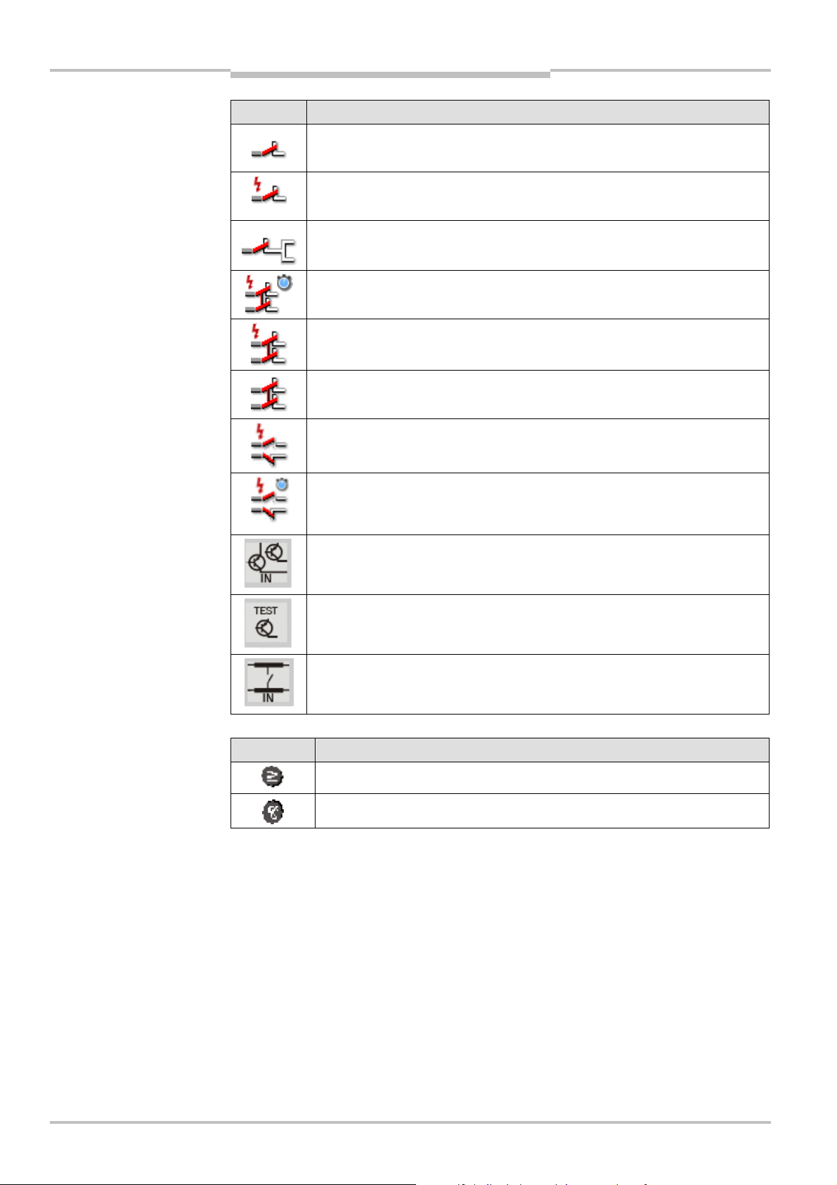
Tab.3:
Input assignment
Tab.4:
Logic symbols
About this document
Flexi Classic
symbols
Symbol Input assignment
Single-channel N/C contact
Single-channel N/C contact, cross-circuit detecting
Single-channel N/C contact at two inputs
Dual-channel N/C contact, equivalent, cross-circuit detecting, with
monitoring of synchronisation (1500 ms)
Dual-channel N/C contact, equivalent, cross-circuit detecting
Dual-channel N/C contact, equivalent
Dual-channel N/C / N/O contact, complementary, cross-circuit detecting
Dual-channel N/C / N/O contact, complementary, cross-circuit detecting,
with monitoring of synchronisation (1500 ms), (e.g. magnetically coded
switch RE300)
Dual-channel semiconductor input, monitored (ESPE)
Single-channel N/C contact/semiconductor input (e.g. sensors that can be
tested)
Switching mats, pressure-sensitive (4-wire system)
Symbol Logic
OR link
AND link
10 © SICK AG • Industrial Safety Systems • Germany • All rights reserved 8011509/YPP0/2015-10-26
Subject to change without notice
Page 11

Operating instructions Chapter 2
Flexi Classic
On safety
2 On safety
This chapter deals with your own safety and the safety of the equipment operators.
= Please read this chapter carefully before working with the Flexi Classic modular safety
controller or with the machine protected by the Flexi Classic modular safety controller.
2.1 Qualified safety personnel
The Flexi Classic modular safety controller must be mounted, commissioned and serviced
only by qualified safety personnel.
Qualified safety personnel are defined as persons who …
• have undergone the appropriate technical training
and
• who have been instructed by the responsible machine operator in the operation of the
machine and the current valid safety guidelines
and
• have access to the operating instructions of the Flexi Classic and those of the particular
modules and have read and familiarised themselves with them
and
• have access to the operating instructions for the protective devices (e.g. C4000)
connected to the safety controller and have read and familiarised themselves with
them.
2.2 Applications of the device
The Flexi Classic modular safety controller is a configurable control system for safety
applications.
The category in accordance with EN ISO 13 849-1 or the SIL in accordance with IEC 61 508
and the SILCL in accordance with EN 62 061 depend on the external circuit, the realisation
of the wiring, the choice of the sensors and their location at the machine.
The device corresponds to up to category 4 in accordance with EN ISO 13 849-1; applications can reach up to SIL3 in accordance with IEC 61 508, up to SILCL3 in accordance
with EN 62 061 or PL e in accordance with EN ISO 13 849-1. The emergency stop function
in the device corresponds to stop category 0 or 1 in accordance with EN 60 204-1.
In order to reach the SIL3 safety level (see chapter 11 “Technical specifications” on
page 96) in accordance with IEC 61 508, the following test must be made at least every
365 days:
• The Flexi Classic system must be powered down.
• The Flexi Classic system must be powered up.
• All safety functions of the connected safety sensors must be verified.
The type of safety sensors as well as the method of wiring must be chosen according to
the category which is to be achieved.
Opto-electronic and tactile safety sensors (e.g. light curtains, laser scanners, safety switches, sensors, emergency stop pushbuttons) are connected to the modular safety controller
and are linked logically. The corresponding actuators of the machines or systems can be
switched off safely via the switching outputs of the safety controller.
The Flexi Classic safety controller has been tested in accordance with UL 508.
8011509/YPP0/2015-10-26 © SICK AG • Industrial Safety Systems • Germany • All rights reserved 11
Subject to change without notice
Page 12

Chapter 2 Operating instructions
On safety
Flexi Classic
2.3 Correct use
The Flexi Classic modular safety controller may only be used as intended in section 2.2
“Applications of the device”. It may only be used by specialist personnel and only at the
machine at which it was mounted and initially commissioned by qualified safety personnel
in accordance with these operating instructions.
If the device is used for any other purposes or modified in any way — also during mounting
and installation — any warranty claim against SICK AG shall become void.
2.4 General safety notes and protective measures
Observe the safety notes and protective measures!
WARNING
Please observe the following items in order to ensure correct use of the Flexi Classic
modular safety controller.
• When mounting, installing and using the Flexi Classic, observe the standards and
directives applicable in your country.
• The national/international rules and regulations apply to the installation, use and
periodic technical inspection of the Flexi Classic modular safety controller, in particular:
– Machinery Directive 2006/42/EC
– EMC Directive 2004/108/EC (valid until 19.04.2016)
EMC Directive 2014/30/EU (valid from 20.04.2016)
– Provision and Use of Work Equipment Directive 2009/104/EC
– Low Voltage Directive 2006/95/EC (valid until 19.04.2016)
Low Voltage Directive 2014/35/EU (valid from 20.04.2016)
– The work safety regulations/safety rules
• Manufacturers and owners of the machine on which a Flexi Classic is used are
responsible for obtaining and observing all applicable safety regulations and rules.
• The notes, in particular the test notes (see chapter 8 “Commissioning” on page 90) of
these operating instructions (e.g. on use, mounting, installation or integration into the
existing machine controller) must be observed.
• The tests must be carried out by qualified safety personnel or specially qualified and
authorised personnel and must be recorded and documented to ensure that the tests
can be reconstructed and retraced at any time by third parties.
• These operating instructions must be made available to the operator of the machine
where the Flexi Classic is used. The machine operator is to be instructed in the use of
the device by qualified safety personnel and must be instructed to read the operating
instructions.
• To meet the requirements of the relevant product standards (e.g. EN 61 496-1), the
external voltage supply for the devices (SELV) must, among other aspects, be able to
bridge a power failure lasting 20 ms. Suitable power supplies are available as accessories from SICK.
• The modules of the Flexi Classic family conform to Class A, Group 1, in accordance with
EN 55 011. Group 1 encompasses all ISM devices in which intentionally generated
and/or used conductor-bound RF energy that is required for the inner function of the
device itself occurs.
12 © SICK AG • Industrial Safety Systems • Germany • All rights reserved 8011509/YPP0/2015-10-26
Subject to change without notice
Page 13

Operating instructions Chapter 2
Flexi Classic
WARNING
WARNING
On safety
The Flexi Classic system complies, as per the “radiated emissions” generic standard,
with the requirements of class A (industrial applications).
The Flexi Classic system is therefore only suitable for use in an industrial environment.
Loss of the safety function through an incorrect configuration!
Plan and carry out configuration carefully!
The configuration of safety applications must be carried out with the greatest accuracy and
must match the status and the condition of the machine or system to be monitored.
= Check whether the configured safety application monitors the machine or system as
planned and whether the safety of a configured application is ensured at all times. This
must be ensured in each operating mode and partial application. Document the result
of this check!
= In each case, observe the instructions for commissioning and daily checking in the
operating instructions of the protective devices integrated into the safety application!
= Note the warnings and function descriptions of protective devices connected to the
safety controller! Contact the respective manufacturer of the protective device if in
doubt!
8011509/YPP0/2015-10-26 © SICK AG • Industrial Safety Systems • Germany • All rights reserved 13
Subject to change without notice
Page 14

Chapter 2 Operating instructions
Tab.5:
Overview on
disposal
On safety
Flexi Classic
2.5 Environmental protection
The Flexi Classic modular safety controller has been designed to minimise environmental
impact. It uses only a minimum of power and natural resources.
= At work, always act in an environmentally responsible manner.
2.5.1 Disposal
Disposal of unusable or irreparable devices should always occur in accordance with the
applicable country-specific waste-disposal regulations (e.g. European Waste Code
16 02 14).
Note
WARNING
We would be pleased to be of assistance to you on the disposal of these devices.
Contact us.
2.5.2 Separation of materials
Material separation may only be performed by qualified safety personnel!
Caution is required when dismantling devices. There is a risk of injuries.
Before you send the devices for appropriate recycling, it is necessary to separate the
different materials in the Flexi Classic.
= Separate the housing from the rest of the parts (in particular the circuit board).
= Send the separated components for recycling as appropriate (see Tab. 5).
by components
Components Disposal
Product
Housing, circuit boards, cables,
connectors and electrical connecting
pieces
Packaging
Cardboard, paper
Electronic recycling
Paper/cardboard recycling
14 © SICK AG • Industrial Safety Systems • Germany • All rights reserved 8011509/YPP0/2015-10-26
Subject to change without notice
Page 15
Operating instructions Chapter 3
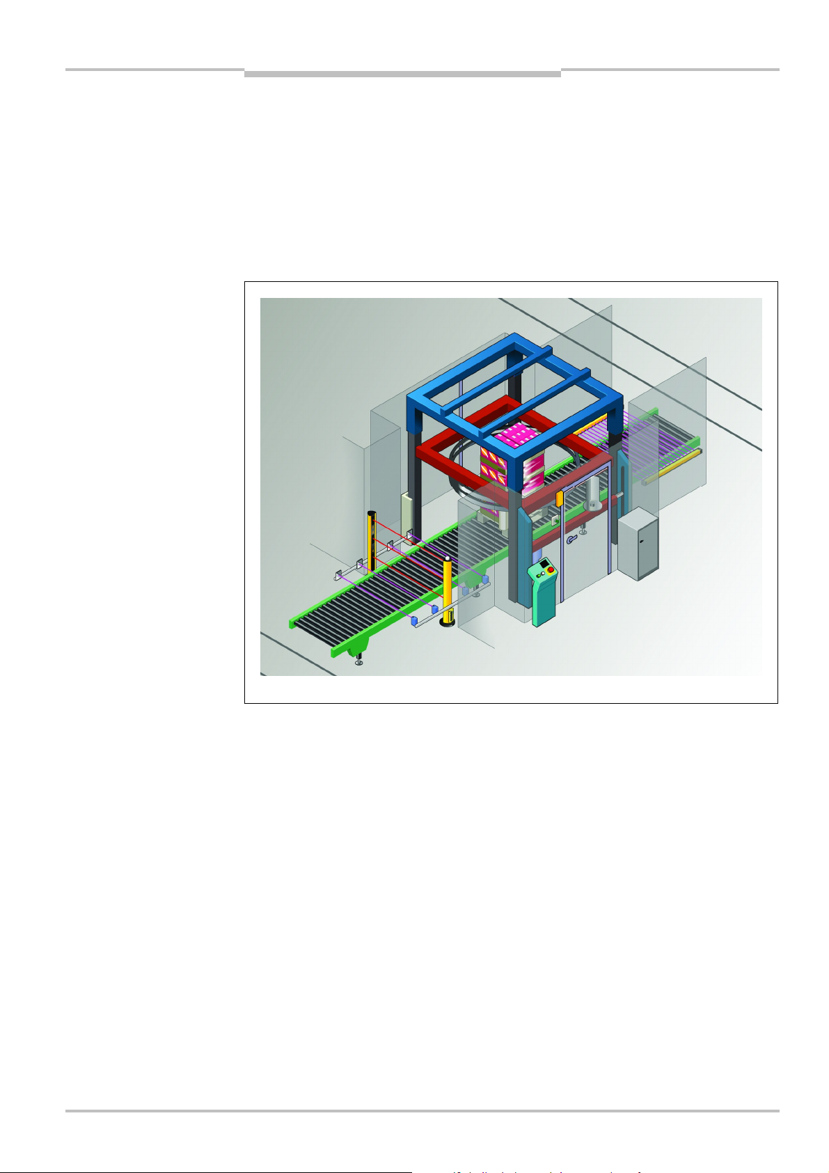
Fig.1:
Flexi Classic
modular
Flexi Classic
Product description
3 Product description
This chapter provides information on the special features and properties of the Flexi
Classic modular safety controller. It describes the construction and the operating principle
of the device.
= Please read this chapter before mounting, installing and commissioning the device.
3.1 Special features
safety controller
The Flexi Classic series is a safety controller concept comprising different modules that
can be interconnected individually. This allows the system to be extended to up to 104
inputs or outputs.
Each of these modules has a compact width of 22.5 mm. The units are of plug-in style with
communication between the individual units over an internal bus.
The required logic and function is specified by means of rotary switches on the modules.
An exception thereof are the relay modules and the fieldbus modules that are used for
integration in a higher level controller without a safety function. These modules are output
units and have no effect on the logic set or the function of the upstream units.
8011509/YPP0/2015-10-26 © SICK AG • Industrial Safety Systems • Germany • All rights reserved 15
Subject to change without notice
Page 16
Chapter 3 Operating instructions
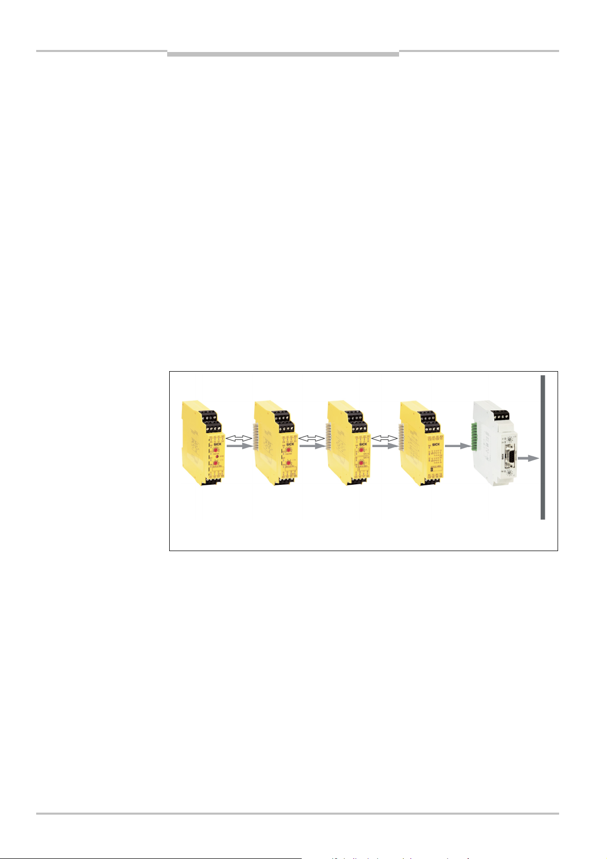
Fig.2:
Safety controller
Product description
Flexi Classic
The Flexi Classic series consists of the following modules:
• main module UE410-MU
• main module UE410-GU
• input/output extension module UE410-XU
• input extension module UE410-8DI
• output modules UE410-2RO and UE410-4RO
• gateways, e.g.
– UE410-PRO (PROFIBUS-DP)
– UE410-CAN (CANopen)
– UE410-DEV (DeviceNet)
– UE410-EN1 (EtherNet/IP)
– UE410-EN3 (Modbus TCP)
– UE410-EN4 (PROFINET IO)
3.2 Structure
A Flexi Classic system always consists of a single main module (UE410-MU or UE410-GU)
and, if necessary, additional input and output extensions as well as a corresponding bus
module.
structure Flexi Classic
(example with UE410-MU)
Main module
4 inputs /4 outputs
Input/output extension module
4 in puts/4 o utputs
Input extension module
8 in puts
UE410-8DIUE410-XUUE410-MU
Output module
2/4 outputs
UE410-2RO/
UE410-4RO
Gateway
E.g. UE410 -PRO, UE410-DEV,
UE410-CAN (see operating
instructions Flexi Classic
Gateways )
3.2.1 UE410-MU main module
The UE410-MU is the main module in which the system configuration of the entire Flexi
Classic system is stored.
The UE410-MU has 4 safety inputs, 4 semiconductor outputs and 2 test outputs. The
9 programs that are available can be set by means of rotary switches that ensure the
connection of a large number of safety components. Functions such as EDM, resetting,
etc. are selected by means of the wiring of S1, S2 and S3. The UE410-MU can control two
applications acting independently as well as two applications that are dependent on each
other.
Fieldbus
16 © SICK AG • Industrial Safety Systems • Germany • All rights reserved 8011509/YPP0/2015-10-26
Subject to change without notice
Page 17

Operating instructions Chapter 3
Flexi Classic
Product description
The devices listed in the following can be connected to the UE410-MU and the modules
connected to it:
• emergency stop pushbuttons
• pressure sensitive mats
• two-hand controllers
• safety switches
• non-contact safety switches (e.g. RE300, T4000 Compact, IN4000)
• single-beam photoelectric safety switches (e.g. L21, L41)
• safety light curtains and multiple light beam safety devices (e.g. MSL, miniTwin,
C/M2000, C/M4000)
• safety laser scanners and safety camera systems (e.g. S300, V300, S3000)
Typical applications such as muting and OR links can be implemented simply, depending
on the setting of the program switch. If additional inputs or outputs are required, the
UE410-MU can be supplemented with a UE410-XU input/output extension module and/or
one or several UE410-8DI input extension modules.
If relay outputs are required, these can be implemented with the UE410-2RO/UE410-4RO
output modules.
Note
3.2.2 UE410-GU main module
The UE410-GU is a main module that can be used as an alternative to the UE410-MU. As
in the UE410-MU, the system configuration for the entire Flexi Classic system is saved in
the UE410-GU. The UE410-GU makes possible a global emergency stop function for several stations connected together that must each be equipped with a UE410-GU. A local
emergency stop is also possible on each UE410-GU.
The UE410-GU has 4 safety inputs (I1-I4), 1 semiconductor output (Q1), 1 output for a
lamp for “Global emergency stop status” and “Reset required” (Q2), 2 test outputs (X1, X2)
and 2 inputs and 2 outputs for the global emergency stop function (IP, IN, OP and ON). The
safe control inputs I5 and I6 are used to connect external device monitoring and a reset
button. The 9 available programs can be set using a rotary switch and make it possible to
connect a variety of safety components.
The following devices can be connected to the UE410-GU:
• emergency stop pushbutton
• safety switch
• non-contact safety switches (e.g. RE300, T4000 Compact)
• single-beam photoelectric safety switches (e.g. L21, L41)
• safety light curtains and multiple light beam safety devices (e.g. MSL, miniTwin,
C/M2000, C/M4000)
• safety laser scanners and safety camera systems (e.g. S300, V300, S3000)
If additional inputs are required, the UE410-GU can be expanded with one or more input
extension modules UE410-8DI.
The UE410-GU can also be expanded with a UE410-XU. This module does not act on the
global emergency stop.
If relay outputs are required, these can be implemented with the UE410-2RO/UE410-4RO
output modules.
The UE410-GU does not support all data sets from all gateways.
8011509/YPP0/2015-10-26 © SICK AG • Industrial Safety Systems • Germany • All rights reserved 17
Subject to change without notice
Page 18

Chapter 3 Operating instructions
Notes
Product description
Flexi Classic
3.2.3 UE410-8DI input extension module
The UE410-8DI module is an input extension with 8 inputs that can be linked using the OR,
AND or Bypass logic function to the respectively upstream UE410-MU, UE410-GU or
UE410-XU module. The 9 switch positions of the UE410-8DI rotary switch determine which
safety components can be connected to the UE410-MU/GU/XU and which type of logic is
used. The input extension module UE410-8DI acts exclusively on the next UE410-MU,
UE410-GU or UE410-XU module positioned to the left in the module structure, thus forming a function group. It is allowed to connect a maximum of 8 UE410-8DI modules to a
UE410-MU, UE410-GU or UE410-XU.
For more informationen on this topic see section 4.12 “Grouping of subsystems” on
page 78.
3.2.4 UE410-XU input/output extension
The UE410-XU module is an input/output extension with 4 safety inputs, 4 semiconductor
outputs and 2 test outputs. It has the same switch positions, logic functions and facilities
for connecting sensors as the UE410-MU. In contrast to the UE410-MU and UE410-GU, the
UE410-XU cannot store the system configuration.
• A UE410-XU can only be operated in combination with a UE410-MU or UE410-GU main
module.
• A main module and a UE410-XU can be linked logically with each other, thus forming a
subsystem (for further information please refer to section 4.12 “Grouping of subsystems” on page 78).
Note
3.2.5 UE410-2RO/UE410-4RO output modules
The UE410-2RO/UE410-4RO output extensions make one or two dual-channel, contactbased outputs available. They do not have any influence on the specified logic instructions
of a system structure and are controlled by the UE410-MU, UE410-GU or UE410-XU outputs.
3.2.6 Gateways
Gateways (fieldbus modules) can be added to the Flexi Classic modular system for diagnostic purposes. They output the system configuration and the input/output states as well
as the error and status information of all the modules.
Several gateways are available, e.g.:
• UE410-PRO for PROFIBUS-DP
• UE410-DEV for DeviceNet
• UE410-EN1 for EtherNet/IP
The UE410-GU does not support all data sets from all gateways.
You will find a complete list of all gateways and the data sets supported in the operating
instructions “Flexi Classic Gateways” or in the Internet on our homepage www.senscontrol.com.
All gateways have 4 non-safe application diagnostic outputs. The outputs are short-circuit
protected (see also the Flexi Classic Gateways operating instructions).
18 © SICK AG • Industrial Safety Systems • Germany • All rights reserved 8011509/YPP0/2015-10-26
Subject to change without notice
Page 19

Operating instructions Chapter 3
Tab.6:
Module overview
Tab.7:
Overview of setting
Flexi Classic
Product description
3.2.7 Module overview, adjustments and facilities for connecting sensors
Module Description
UE410-MU
• Main unit of the Flexi Classic modular safety
controller
• 4 safe inputs and 4 safe outputs
• Storage of the system configuration
UE410-GU
• Central function block of the Flexi Classic
modular safety controller
• Global emergency stop can be realized
• 4 safe inputs
• 1 safe output
• Storage of the system configuration
UE410-XU • Input/output extension/subsystem
• 4 safe inputs and 4 safe outputs
• Identical functionality as UE410-MU
UE410-8DI • Input extension
• 8 safe inputs
• Information coupling to the upstream UE410-
MU, UE410-GU or UE410-XU module
UE410-2RO 2 contacts (N/O), 1 signal contact (N/C)
possibilities
UE410-4RO 4 contacts (N/O), 2 signal contacts (N/C)
Flexi Classic gateways
e.g. UE410-PRO, UE410-DEV,
UE410-CAN
Setting possibility Can be set at the module Comment
ENTER button UE410-MU/UE410-GU
Status and diagnostics (information that is not
safety relevant) of a Flexi Classic on a fieldbus
(see Flexi Classic Gateways operating instructions)
Saving of all Flexi Classic system
programs, settings and wiring
Program 1-9
UE410-MU/UE410GU/UE410-XU
Selection of the safety sensors
and of the logic elements to be
connected
Off delay
0-5 s, 0-50 s or
0-300 s
UE410-MU/UE410-XU
Delays 1 or 2 outputs on the
module
3 different variants available
(Not on UE410-xxxT0)
Switch position 0-9 UE410-8DI
Selection of the logic elements
and of the safety sensors to be
connected
8011509/YPP0/2015-10-26 © SICK AG • Industrial Safety Systems • Germany • All rights reserved 19
Subject to change without notice
Page 20
Chapter 3 Operating instructions
Tab.8:
Connection of sen
-
Product description
Flexi Classic
sors to the UE410-MU,
UE410-XU and UE410-8DI
Sensor
Program
UE410-MU/UE410-XU UE410-8DI
A (I1/I2) B (I3/I4) A (I1-I4) B (I5-I8)
7, 8 1, 2, 7, 8, 9 1, 6, 7 1, 6, 7
7, 8 1, 2, 7, 8, 9 6, 7 6, 7
1, 5, 6, 9 5, 6 2, 3, 8 2, 3, 8
– – 4 4
2 – 5 5
1 – 2 2
3, 7, 8 1, 2, 7, 8, 9 6, 7 6, 7
3, 7, 8 1, 2, 7, 8, 9 6, 7 6, 7
3, 7, 8 1, 2, 7, 8, 9 6, 7 6, 7
20 © SICK AG • Industrial Safety Systems • Germany • All rights reserved 8011509/YPP0/2015-10-26
Subject to change without notice
Page 21
Operating instructions Chapter 3
Flexi Classic
Product description
Sensor
Program
UE410-MU/UE410-XU UE410-8DI
A (I1/I2) B (I3/I4) A (I1-I4) B (I5-I8)
4 4 – –
– 5.2 – –
– 5.1 – –
2 – 5 5
3 – – –
1, 5, 6, 7, 8
1, 2, 6, 7, 8,
2, 3, 6, 7, 8 2, 3, 6, 7, 8
9
3 – 1 1
3 3 – –
1, 5, 6, 9 5, 6 2, 3, 8 2, 3, 8
8011509/YPP0/2015-10-26 © SICK AG • Industrial Safety Systems • Germany • All rights reserved 21
Subject to change without notice
Page 22
Chapter 3 Operating instructions
Fig.3:
Scheme programs 1
-3Fig.4:
Scheme program 4
Product description
Flexi Classic
3.3 UE410-MU main module
The UE410-MU main module is the main module of the Flexi Classic modular safety controller. Only one UE410-MU can be integrated for each Flexi Classic system. A UE410-MU
can control up to two applications acting independently or two applications that are dependent on each other.
In order to increase the number of inputs, one or more UE410-8DI extension modules can
be used additionally.
An additional UE410-XU module can be used in order to increase the number of outputs
(for further information refer to section 4.12 “Grouping of subsystems” on page 78).
The system configuration is stored in the UE410-MU main module (ENTER button to accept
the program settings and system configuration) (for further information refer to section 9.1
“Accepting the system configuration” on page 92).
9 programs that can be set with a screwdriver at the program switch are available.
22 © SICK AG • Industrial Safety Systems • Germany • All rights reserved 8011509/YPP0/2015-10-26
Subject to change without notice
Page 23
Operating instructions Chapter 3
Fig.5:
Scheme
Fig.6:
Scheme program 8
Flexi Classic
programs 5-7, 9
Product description
Note
WARNING
The following functions can be set by selecting the program and connecting the terminals
S1, S2, and S3 at the module:
• type of the logic and of the safety sensors to be connected
• restart interlock
• external device monitoring (EDM)
Q1 and Q2 always switch off within the response time.
Q31) and Q4 can be deactivated with off delay by using the lower rotary switch (depending
on the device variant 0-5 s/0-50 s/0-300 s/not on UE410-xxxT0).
The outputs are tested periodically in order to detect errors in the safety outputs Q1-Q4.
When using XU modules see section 4.12 “Grouping of subsystems” on page 78.
For further information see section 3.6 “UE410-MU/UE410-XU programs” on page 36.
Subsequent changes to the program or to the wiring (S1-S3) without saving will result in a
safety-related shutdown.
8011509/YPP0/2015-10-26 © SICK AG • Industrial Safety Systems • Germany • All rights reserved 23
Subject to change without notice
1)
Q3 has various functions; see section 3.6 “UE410-MU/U E410-XU programs” on page 36.
Page 24
Chapter 3 Operating instructions
Fig.7:
UE410
-
MU controls
Tab.9:
UE410
-
MU
Button for accepting the
Program switch
Switch for off delay
Product description
Flexi Classic
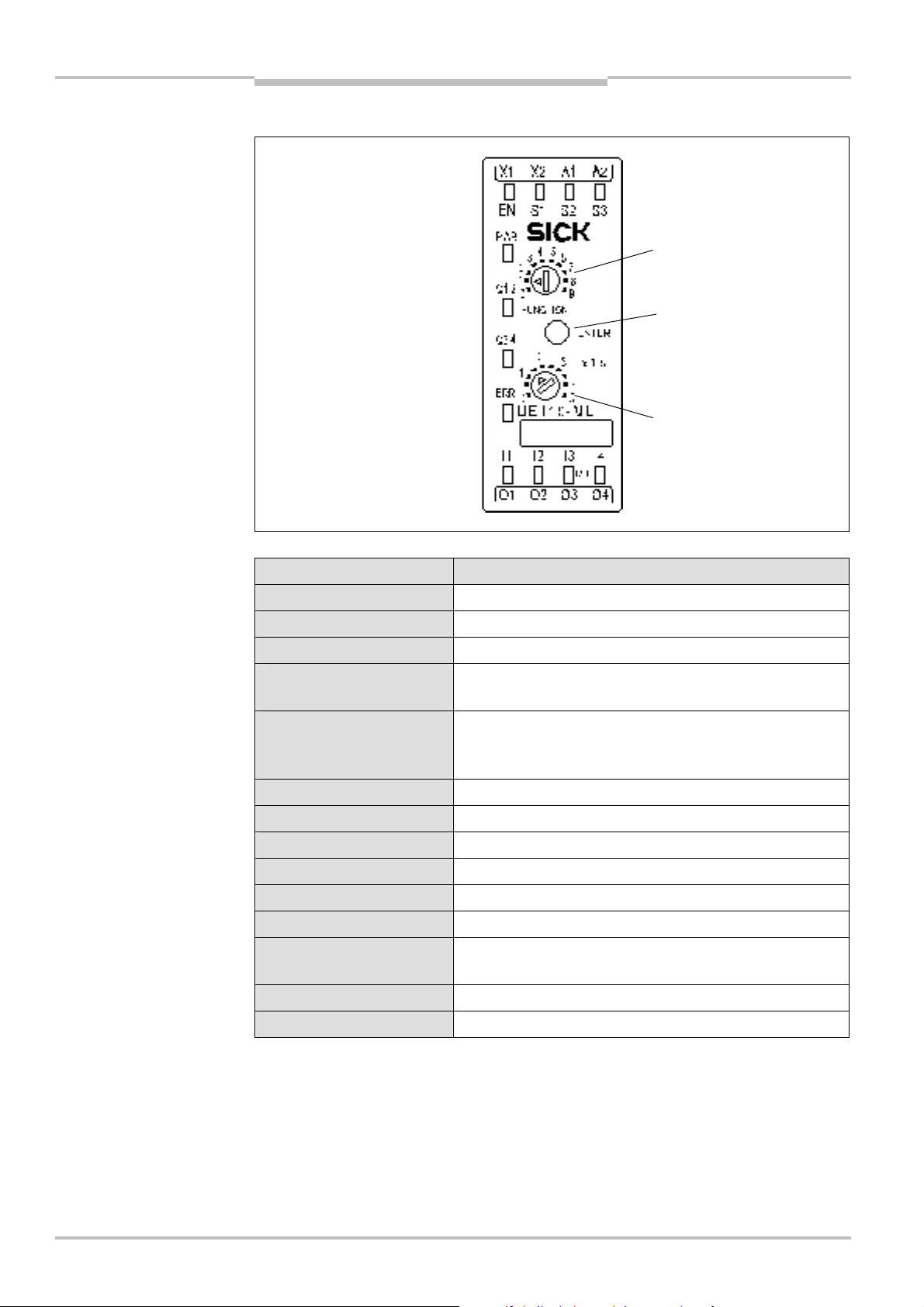
3.3.1 Controls and status indicators
and status indicators
system configuration
(not on UE410-xxxT0),
see Tab. 10
indications
LED indicators Meaning
PWR (green) Supply voltage present
Q1/Q2, Q3/Q4 (green) Switching state of the safety outputs (high level)
Q3/Q4 (green flashing) Q3/Q4 to high level during the course of the delay time
ERR (red flashing)
Indication for erroneous operational status on this
module, see chapter 10 “Diagnostics” on page 93
ERR (red)
Indication for erroneous operational status on the whole
system (the error is on another module), see chapter 10
“Diagnostics” on page 93
EN, S1-S3 (green) Voltage is present.
I1-I4 (green) Signal is present.
I1/I2 flash in phase Cross-circuit between I1/I2
I3/I4 flash in phase Cross-circuit between I3/I4
I1/I2 flash out of phase Process error at I1/I2
I3/I4 flash out of phase Process error at I3/I4
I1 to I4 flashes
Synchronization time/concurrence error, expected signal
is not present at the respective input.
S1-S3 flashes Expected signal is not present (e.g. EDM or Reset).
24 © SICK AG • Industrial Safety Systems • Germany • All rights reserved 8011509/YPP0/2015-10-26
Other indicators Device error, see chapter 10 “Diagnostics” on page 93
Subject to change without notice
Page 25

Operating instructions Chapter 3
Tab.10:
UE410
-MU
Tab.11:
UE410
-
MU terminal
Flexi Classic
Product description
operating elements
assignment
Switch/button Function
FUNCTION
10-step rotary switch (position 0 forbidden) for setting an input
circuit function (see section 3.6 “UE410-MU/UE410-XU programs”
on page 36)
X1s, X10s,
2)
X1min
10-step rotary switch for setting the off delay time (see section 3.6
“UE410-MU/UE410-XU programs” on page 36)
ENTER Button for accepting the system configuration (Teach-in).
See section 9.1 “Accepting the system configuration” on page 92.
3.3.2 Terminal assignment
Assignment Description
I1/I2 Input for logic path A
I3/I4 Input for logic path B
EN ENABLE input, activates the logic path(s)
S1
S2
Input for reset buttons (RESET), restart interlock (EDM), retriggering,
etc.
S3
A1 (+UB)
Voltage supply
A2 (GND)
X1
X2
Test outputs: cross-circuit detecting and short-circuit detecting control
signals for controlling safety sensors
3)
Q1-Q4 Monitored semiconductor outputs (OSSD)
Q3
Is used in Program 3 as the output for the muting lamp and Reset
required.
3)
2)
The maximum adjustable duration of the switch off delay is 5, 50 or 300 s depending on the device variant,
see section 12.1 “Available modules” on page 112.
3)
When using multiple modules see section 4.12 “Grouping of subsystems” on page 78.
8011509/YPP0/2015-10-26 © SICK AG • Industrial Safety Systems • Germany • All rights reserved 25
Subject to change without notice
Page 26

Chapter 3 Operating instructions
WARNING
Product description
Flexi Classic
3.3.3 Outputs
You have two possibilities to reach SIL3 or Category 4 for your application:
• dual-channel wiring of the outputs, e.g. Q1/Q2 to K1/K2
or
• single-channel wiring only with routing within protected areas such as in a control
cabinet, e.g. Q1 to K1/K2.
Safety-oriented devices must be suitable for safety related signals!
A function interruption of safety outputs results in a loss of the safety functions so that the
risk of serious injury exists.
• Do not connect any loads that exceed the rated values of the safety outputs.
• Wire the Flexi Classic system so that 24 V DC signals cannot contact the safety outputs.
• Connect the GND wires of the power supply to earth so that the devices do not switch
on when the safety output line is applied to frame potential.
• Use suitable components or devices that fulfil all the applicable regulations and
standards.
Actuators at the outputs can be wired single-channeled. In order to maintain the respective
Safety Integrity Level the lines have to be routed in such a manner that cross circuits to
other live signals can be excluded, for example by routing them within protected areas
such as in a control cabinet or in separate plastic-sheathed cables.
26 © SICK AG • Industrial Safety Systems • Germany • All rights reserved 8011509/YPP0/2015-10-26
Subject to change without notice
Page 27

Operating instructions Chapter 3
Flexi Classic
Product description
3.4 UE410-GU main module
The UE410-GU is a main module that can be used as an alternative to the UE410-MU. The
system configuration is stored in the main module (for further information please refer to
section 9.1 “Accepting the system configuration” on page 92).
Only one UE410-GU can be used per Flexi Classic system.
In order to increase the number of inputs, one or more UE410-8DI extension modules can
be used additionally.
To increase the number of outputs, an additional UE410-XU can be used (see section 4.12
“Grouping of subsystems” on page 78). A total of up to 12 Flexi Classic modules and one
gateway can be connected to the UE410-GU.
The UE410-GU makes possible a global emergency stop function for several stations connected together that must each be equipped with a UE410-GU. If the global emergency
stop on a module is operated, the safety outputs on all modules switch off. To reset a global emergency stop, the reset button must be operated on the same module on which the
global emergency stop was triggered.
Note
A global emergency stop must always be reset manually.
Along with the global emergency stop function, on each module it is also possible to select
a local emergency stop function with or without restart interlock. The local emergency stop
only acts on the safety output on the related module. A local emergency stop can be reset
either automatically or manually.
The safety output Q1 always switches within the response time. A switch off delay as on
the UE410-MU is not possible with the UE410-GU.
Different programs for the local inputs can be selected with the aid of a rotary switch.
9 programs are available using which the following functions can be set:
• type of the safety sensors to be connected
• global emergency stop or global and local emergency stop
• automatic or manual reset of a local emergency stop
For further information see section 3.7 “UE410-GU programs” on page 49.
WARNING
Subsequent changes to the program will result in a safety-related shutdown without
saving.
8011509/YPP0/2015-10-26 © SICK AG • Industrial Safety Systems • Germany • All rights reserved 27
Subject to change without notice
Page 28
Chapter 3 Operating instructions
Fig.8:
UE410
-
GU controls
Tab.12:
UE410
-
GU
Tab.13:
UE410
-
GU
Program switch
Button for accepting the
Product description
Flexi Classic
3.4.1 Controls and status indicators
and status indicators
system configuration
indications
LED indicators Meaning
PWR (green) Supply voltage is present.
Q1 (green) Safety output Q1 is high.
ERR (red flashing)
Indication for erroneous operational status on this module, see
chapter 10 “Diagnostics” on page 93
ERR (red)
Indication for erroneous operational status on the whole system
(the error is on another module), see chapter 10 “Diagnostics”
on page 93
I1/I2 (green) Global cut-off path closed
I3/I4 (green) Cut-off path closed
I1/I2 (green flashing
Cross-circuit between I1/I2
in phase)
I3/I4 (green flashing
Cross-circuit between I3/I4
in phase)
I1/I2 (green flashing
Process error at I1/I2
out of phase)
I3/I4 (green flashing
Process error at I3/I4
out of phase)
I5 (green) External device monitoring contact is closed.
operating elements
28 © SICK AG • Industrial Safety Systems • Germany • All rights reserved 8011509/YPP0/2015-10-26
I6 (green) Reset button is closed.
IP (green) Input IP is high.
IN (green) Input IN is high.
Other indicators Device error, see chapter 10 “Diagnostics” on page 93
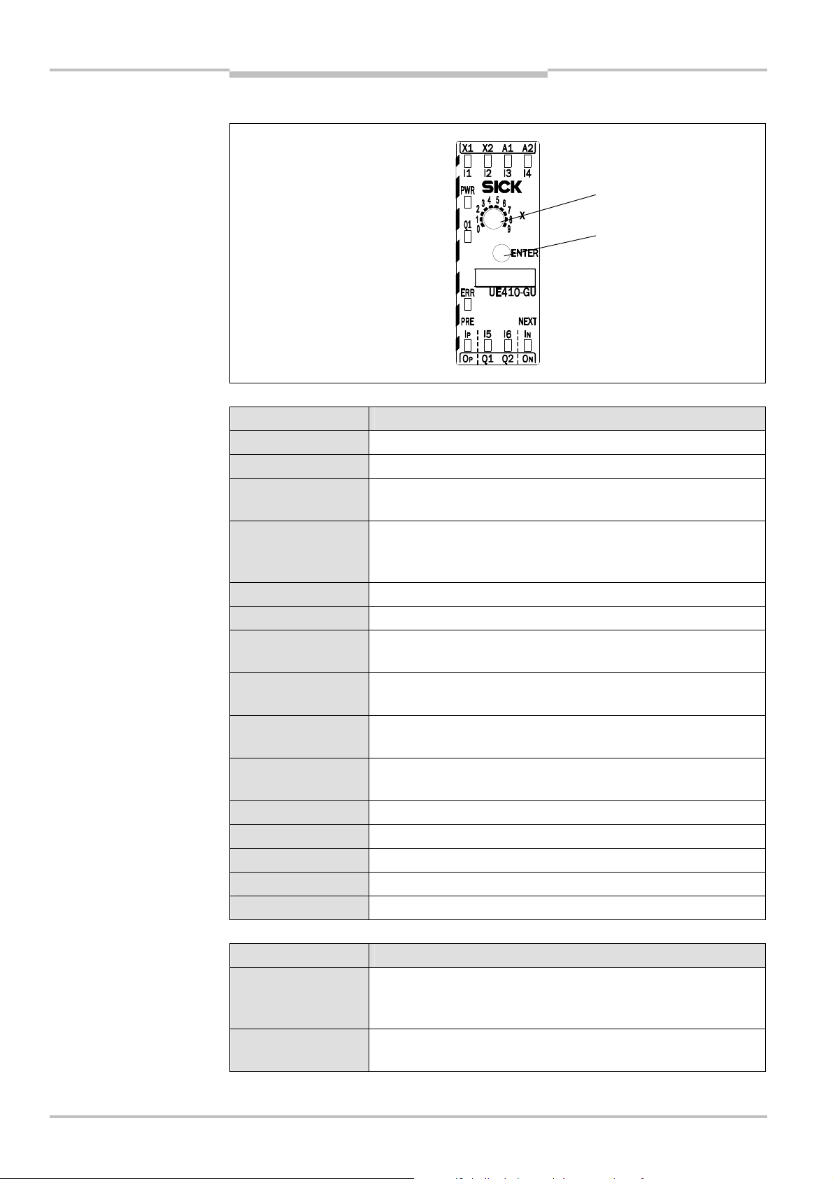
Switch/button Function
X
10-step rotary switch (position 0 forbidden) for setting an input
circuit function, see section 3.7 “UE410-GU programs” on
page 49
ENTER
Button for accepting the system configuration (Teach-in), see
section 9.1 “Accepting the system configuration” on page 92
Subject to change without notice
Page 29

Operating instructions Chapter 3
Tab.14:
UE410
-
GU terminal
Flexi Classic
Product description
3.4.2 Terminal assignment
assignment
Assignment Description
I1/I2 Global emergency stop (equivalent switch with test pulses)
I3/I4
Local emergency stop (local input, depending on the program
set)
A1 (+UB)
Voltage supply
A2 (GND)
X1
X2
Q1 Single-channel safety output (OSSD)
Q2
Test outputs: cross-circuit detecting and short-circuit detecting
control signals for controlling safety sensors
4)
4)
Connection for the lamp for “Global emergency stop status” and
“Reset required”
I5 Connection for the external device monitoring (EDM)
I6 Connection for the reset button
I
P
I
N
O
P
O
N
Input signal from the previous module (PRE_IN)
Input signal from the next module (NEXT_IN)
Output signal to the previous module (PRE_OUT)
Output signal to the next module (NEXT_OUT)
Notes
3.4.3 Global emergency stop with the UE410-GU
The global emergency stop makes possible the simultaneous shut down of the safety outputs on several Flexi Classic stations connected together that are each equipped with a
UE410-GU as the main module.
• In theory as many UE410-GU modules as required can be connected together to form a
global emergency stop system. However, it is recommended not to exceed 32 modules,
because each module increases the response time of the overall system (see the information on the global response time in section 11.1.2 “UE410-GU module” of the technical data on page 101).
• The different UE410-GU modules that together form a global emergency stop circuit do
not need to be in the same protected area. Faults in the area OX and IX, e.g. a shortcircuit or cross circuit, are detected and will result in shutdown.
• All UE410-GU modules that are on a common global emergency stop cut-off path must
be connected to the same GND connection.
Principle of operation
As long as the system is enabled, each UE410-GU sends a signal to the previous UE410GU (PRE) and to the next UE410-GU (NEXT). If the global emergency stop is activated on a
module (falling edge on I1/I2), then this module sets its safety output Q1 as well as the
signals to its neighboring modules (outputs OP and ON) to low. The neighboring modules
now also set their safety output Q1 as well as their outputs OP and ON to low.
The status of the global emergency stop is also output via the output Q2. If the global
emergency stop is activated on this UE410-GU, this status is indicated with a signal
flashing at 2 Hz on output Q2. If the global emergency stop has been activated on another
UE410-GU, then this status is indicated with a continuous high on output Q2.
4)
When using multiple modules see section 4.12 “Grouping of subsystems” on page 78.
8011509/YPP0/2015-10-26 © SICK AG • Industrial Safety Systems • Germany • All rights reserved 29
Subject to change without notice
Page 30
Chapter 3 Operating instructions
Fig.9:
Connecting several
First module
Last module
Module(s) in the middle
Product description
Flexi Classic
Once the cause of the global emergency stop has been rectified (inputs I1 and I2 are high
again, e.g. protective field clear), then the UE410-GU on which the global emergency stop
was originally triggered signals on output Q2 the status Reset required with a signal
flashing at 1 Hz.
Reset
A global emergency stop can only be reset manually. The reset must be undertaken on the
same module on which the global emergency stop was triggered.
Once the global cut-off path for this module is closed again (inputs I1 and I2 are high
again, e.g. protective field clear) and the reset button on this module is then operated, the
safety output Q1 on this module as well as the outputs OP and ON switch to high again.
The following conditions are to be noted for the reset:
• Only the falling edge is evaluated.
• The minimum actuation time for the reset button is ≥ 50 ms.
• The maximum actuation time for the reset button is ≤ 5 s.
If one of these criteria is not met, the emergency stop is not reset.
Wiring of the modules
To connect several UE410-GU modules together, the input IN on the previous UE410-GU
must be connected to the output OP on the next UE410-GU and the output ON on the previous UE410-GU must be connected to the input IP on the next UE410-GU.
For the specification of the connection cable please refer to the data sheet in section 11.1.2 “UE410-GU module” on page 101.
The first and last UE410-GU in an emergency stop system act as end modules. An end
module is a UE410-GU that has only one neighboring station. These modules are defined
by the wiring of the outputs X1 and X2.
• The end module without PRE is defined by wiring X1 to IP.
• The end module without NEXT is defined by wiring X2 to IN.
This wiring is saved with the configuration and checked each time on switching on.
UE410-GU modules
30 © SICK AG • Industrial Safety Systems • Germany • All rights reserved 8011509/YPP0/2015-10-26
Subject to change without notice
Page 31

Operating instructions Chapter 3
Flexi Classic
WARNING
Product description
Test the entire emergency stop function after any change to the wiring!
If a UE410-GU is subsequently removed from an emergency stop system and the system is
then correctly wired, this change will not be detected. For this reason the entire emergency
stop function must always be tested after any change to the wiring.
Stand-alone mode of a UE410-GU
It is also possible to operate a UE410-GU as a standalone device. For this purpose X1
must be wired to IP and X2 must be wired to IN on this device.
3.4.4 Local emergency stop on the UE410-GU
A local emergency stop can be configured on each UE410-GU depending on the program
set (see section 3.7 “UE410-GU programs” on page 49).
Principle of operation
If the local emergency stop is activated on a UE410-GU (falling edge on I3 and/or I4, depending on the program set), this module sets its safety output Q1 to low. The signals O
and ON remain high, i.e. the local emergency stop only acts on the safety output on the
UE410-GU on which the local emergency stop was triggered.
Once the cause of the local emergency stop has been rectified (inputs I3 and I4 are high
again, e.g. protective field clear), the safety output Q1 on the module switches to high
again after a successful reset.
P
Reset
A local emergency stop can be reset either manually or automatically depending on the
program set:
• Automatic reset: Once the local cut-off path is closed again (e.g. protective field clear),
then the safety output Q1 on the module also switches to high again.
• Manual reset: Once the local cut-off path is closed again (e.g. protective field clear),
output Q2 starts to flash at 1 Hz. If the reset button is then operated, the safety output
Q1 on the module switches to high again.
The following conditions are to be noted for the manual reset:
• Only the falling edge is evaluated.
• The minimum actuation time for the reset button is ≥ 50 ms.
• The maximum actuation time for the reset button is ≤ 5 s.
If one of these criteria is not met, the emergency stop is not reset.
8011509/YPP0/2015-10-26 © SICK AG • Industrial Safety Systems • Germany • All rights reserved 31
Subject to change without notice
Page 32

Chapter 3 Operating instructions
Notes
Product description
Flexi Classic
3.4.5 Inputs
Connection of the emergency stop pushbutton for the global emergency stop
(I1 and I2)
A two-pole equivalent safety switch must be connected to the inputs I1 and I2 as the
emergency stop pushbutton for the global emergency stop. The emergency stop pushbutton is tested via the connection of X1–I1 and X2–I2.
Connection of the sensors for the local emergency stop (I3 and I4)
The sensors for the local emergency stop are connected to the inputs I3 and I4 (see section 3.7 “UE410-GU programs” on page 49). The sensors are tested via the connection of
X1–I3 and X2–I4.
Connection of the external device monitoring (EDM) (I5)
The external device monitoring (EDM) is connected to I5.
Before each enable it is checked whether I5 is high. If this condition is not met, the safety
output Q1 is not set to high.
Connection of the reset button (I6)
The reset button must be connected to input I6.
• The reset button acts both as a reset button for the global emergency stop and for the
local emergency stop, if a program with manual reset is set for the local emergency stop
(program 2, 4, 6 or 8) (see section 3.7 “UE410-GU programs” on page 49).
• If a program with automatic reset is set for the local emergency stop, then the reset
button only acts on a global emergency stop, i.e. if a global emergency stop has been
triggered on the module and the module has the status Reset required.
WARNING
WARNING
3.4.6 Outputs
Lay the single-channel connection in a protected area!
To achieve SIL3 or category 4, you must lay the single-channel connection Q1 to K1/K2
such that cross-circuits to other electrical signals can be excluded, e.g. by laying in pro-
tected areas such as in a control cabinet or in separate plastic-sheathed cables.
Safety-relevant devices must be suitable for safety-relevant signal requirements!
Serious injury may occur due to breakdown of safety outputs or loss of required safety
functions.
• Do not connect loads that exceed the rated value of the safety outputs.
• Wire the Flexi Classic system so that 24 V DC signals cannot contact the safety outputs.
• Connect the GND wires of the power supply to earth so that the devices do not switch
on when the safety output line is applied to frame potential.
• All UE410-GU modules that are on a common global emergency stop cut-off path must
be connected to the same GND connection.
• Use appropriate components or devices in accordance with regulations and standards.
32 © SICK AG • Industrial Safety Systems • Germany • All rights reserved 8011509/YPP0/2015-10-26
Subject to change without notice
Page 33

Operating instructions Chapter 3
Flexi Classic
Note
Product description
3.4.7 Connection of a UE410-8DI
A UE410-8DI acts on the cut-off path A/B on a UE410-GU as follows:
• Input A (I1-I4) , QA acts on the global cut-off path.
• Input B (I5-I8) , QB acts on the local cut-off path.
An OR function or a bypass function that acts on the global cut-off path of the UE410-GU
(switch position 7 or 8, input A on the UE410-8DI) is not permitted and will result in a
configuration error (ERROR).
3.4.8 Power-up delay and response time of the UE410-GU
Power-up delay
The power-up delay of the UE410-GU is calculated as follows:
Power-up delay = local power-up delay + (N–1) × global power-up delay
Where:
Local power-up delay = power-up delay for the module on which the emergency stop was
triggered and reset
Global power-up delay = power-up delay of the other modules in the system
N = number of the UE410-GU modules in the system
You will find the values for the power-up delay on the data sheet in section 11.1.2 “UE410GU module” on page 101.
WARNING
Response times
Extended response time of the overall system on the usage of several UE410-GU
modules!
In a system consisting of several UE410-GU modules connected together, the power-up
delay and the response time are increased depending on the number of UE410-GU modules connected together. Take this aspect into account on planning your system. Otherwise the operator of the system will be in danger.
The response time of the UE410-GU is calculated as follows:
Response time = local response time + (N–1) × global response time
Where:
Local response time = response time of the module on which the emergency stop was
triggered
Global response time = response time of the other modules in the system
N = number of the UE410-GU modules in the system
You will find the values for the response times on the data sheet in section 11.1.2
“UE410-GU module” on page 101.
3.4.9 Diagnostics and troubleshooting for the UE410-GU
If a system with a global emergency stop function comprising several UE410-GU modules
is either entirely or partially at the standstill, then you can determine which module has
triggered the emergency stop as follows:
= Based on the LED indicators on any UE410-GU module in the system check whether the
emergency stop has been triggered by this module or the direction of the module that
has triggered the global or local emergency stop, see Tab. 15.
8011509/YPP0/2015-10-26 © SICK AG • Industrial Safety Systems • Germany • All rights reserved 33
Subject to change without notice
Page 34

Chapter 3 Operating instructions
Fig.10:
Diagnostic displays
Tab.15:
Diagnostics on the
Tab.16:
Significance of the
LED I3/I4: sensor with local
LED Q1: safety
output Q1
LED I1/I2: emergency stop
LED I
: status of all previous
LED I
: status of all next
on the UE410-GU
Product description
Flexi Classic
UE410-GU
Ν The LED or lamp is
illuminated constantly.
∏ The LED or lamp is
flashing (1 Hz).
⌠∏ The LED or lamp is
flashing (2 Hz).
ν The LED or lamp is off.
X Any
pushbutton with global action
P
modules
action
N
modules
= Also pay attention to the lamp on output Q2 (“Global emergency stop status”, “Reset
required”) on the related UE410-GU.
Q1 I1/I2 I3/I4 I
ν Ν ν Ν Ν ν
I
P
Lamp Q2 Cause
N
A local emergency stop has been
triggered on this station.
ν Ν X ν X Ν
A previous station has triggered a
global emergency stop.
ν Ν X X ν Ν
A next station has triggered a global
emergency stop.
Note
diagnostics LEDs I5 and I6 on
the UE410-GU
ν ν X X X ⌠∏
A global emergency stop has been
triggered on this station.
ν Ν Ν Ν Ν ∏ Reset is required on this station.
Ν Ν Ν Ν Ν ν
The safety output on the module is
active and the system enabled.
A combination of several causes may occur, e.g. if a local emergency stop and a global
emergency stop have been triggered.
LED I5 and I6 indications
In normal operation with safety output Q1 active the LEDs I5 and I6 are ν Off.
LED Meaning
I5 illuminates Ν Green
The safety output Q1 is shut down, the external actuators
have dropped out. Otherwise check the wiring.
I5 flashes ∏ Green
EDM error. Check the wiring. If necessary, replace the
actuator.
I6 illuminates Ν Green The reset button is pressed. Otherwise check the wiring.
I6 flashes ∏ Green
The reset button has been operated for too long. Check the
wiring if necessary.
Also note the description of the LED indicators on the UE410-GU in section 3.4.1 “Controls
and status indicators” on page 28 as well as chapter 10 “Diagnostics” on page 93.
34 © SICK AG • Industrial Safety Systems • Germany • All rights reserved 8011509/YPP0/2015-10-26
Subject to change without notice
Page 35

Operating instructions Chapter 3
Fig.11:
UE410
-
XU controls
Program switch
Switch for off delay
Flexi Classic
Product description
3.5 UE410-XU module
The UE410-XU module is an input/output extension or a subsystem with 4 safe inputs and
outputs. It has the identical functionality to the UE410-MU main module, however without
the system save using the ENTER button.
The UE410-XU cannot be used as a stand-alone device and always requires a UE410-MU
main module.
3.5.1 Controls and status indicators
and status indicators
(not on UE410-xxxT0)
Indicators, controls and terminal assignments are the same as on the UE410-MU main
module (see Tab. 9-Tab. 11).
8011509/YPP0/2015-10-26 © SICK AG • Industrial Safety Systems • Germany • All rights reserved 35
Subject to change without notice
Page 36

Chapter 3 Operating instructions
Tab.17:
UE410-MU/UE410
-
Product description
Flexi Classic
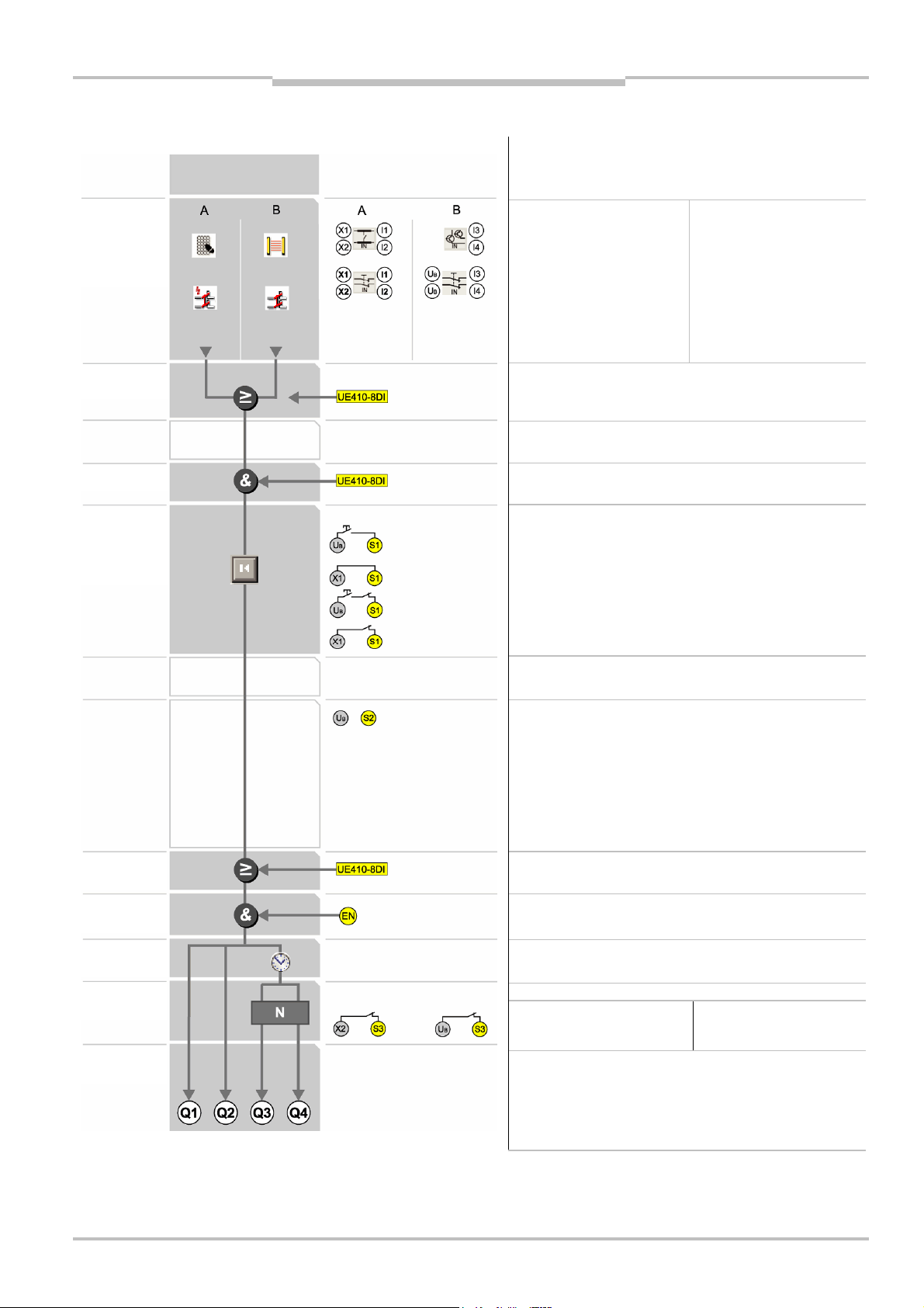
3.6 UE410-MU/UE410-XU programs
The modules have 9 settable programs each that can be set via a rotary switch.
Up to two applications acting independently or two applications that are dependent on
each other (A and B) can be controlled. These can act independently or dependent on
each other, depending on the program (see Fig. 3-Fig. 6).
The program selection determines the type of safety sensor equipment to be connected
and the logic instructions.
XU programs
Program Description
0 Module inactive
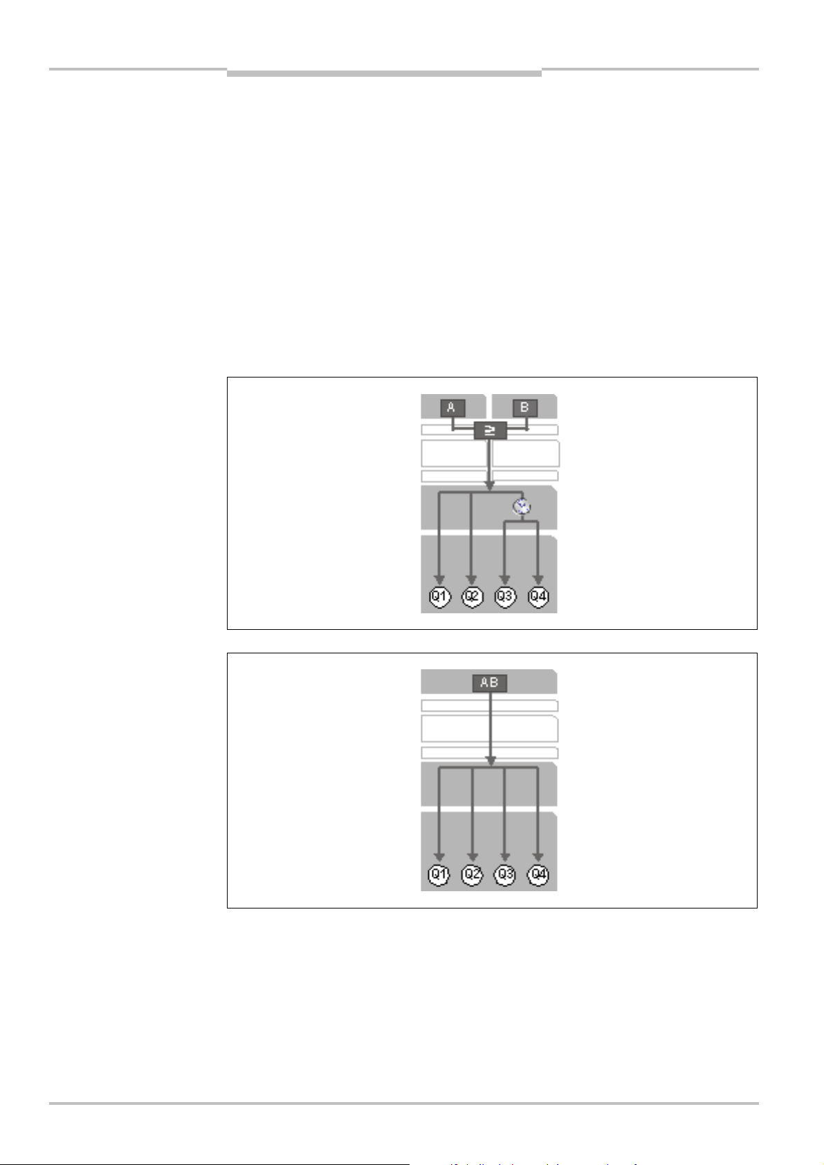
1-2
Input control circuit A is linked by means of OR logic to input control
circuit B and acts on all the safety outputs Q1-Q4.
3.1-3.2 • Input control circuit A acts on the safety outputs Q1, Q2, Q4.
• Input control circuit B is muting input and controls the muting lamp
via Q3.
4 Input control circuit AB acts on all the safety outputs AB (two-hand IIIC).
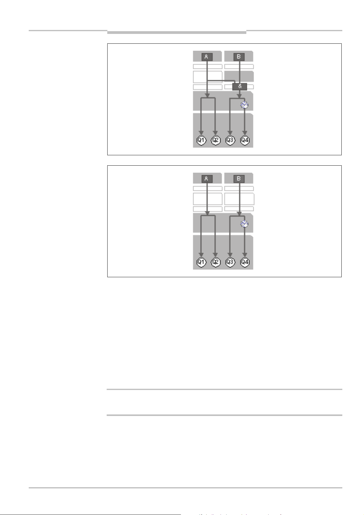
5-7 • Input control circuit A acts on both safety outputs Q1/Q2 and Q3/Q4.
• Input control circuit B acts only on the safety output Q3/Q4.
8 • Input control circuit A acts only on the safety output Q1/Q2.
• Input control circuit B acts only on the safety output Q3/Q4.
9 • Input control circuit A acts on both safety outputs Q1/Q2 and Q3/Q4.
• Input control circuit B acts only on the safety output Q3/Q4.
36 © SICK AG • Industrial Safety Systems • Germany • All rights reserved 8011509/YPP0/2015-10-26
Subject to change without notice
Page 37
Operating instructions Chapter 3
Inputs/
OR
AND
Restart
Bypass
ENABLE
Retriggering
Product description
Flexi Classic
3.6.1 Program 1
1 logic path
sensors
interlock
A
Dual-channel equivalent N/C
contact
Cross-circuit detecting control
signals
Synchronous time monitoring
(1500 ms)
Pressure-sensitive switching
mats (four-wire)
Flexi Loop
OR with UE410-8DI — switch position 7
AND with UE410-8DI — switch position 1-6
Connecting of S1:
∂ with restart interlock Q1/Q2, without EDM
∂ without restart interlock Q1/Q2, without EDM
∂ with restart interlock Q1/ Q2, with EDM
∂ without re start interlock Q 1/Q2, with EDM
B
Single-channel N/C contact
Dual-channel equivalent N/C
contact ( not cross-circuit
detecting)
ESPE (sensors with
semiconductor output)
Off delay
Outputs
Connecting of S2:
S2 may not be connected.
OR limited 60 s with UE410-8DI — switch position 8
Always wire ENABLE (expected 24 V DC)!
At ENABLE low Q1-Q4 are always low.
Off delay acts on Q3/Q4
(not on UE410-xxxT0).
Connecting of S3:
with/without EDM Q3/Q4
∂ retriggering ON
Undelayed OSSDs Q1/Q2
Delayable OSSDs Q3/Q4
with/without EDM Q3/Q4
∂ retriggering OFF
8011509/YPP0/2015-10-26 © SICK AG • Industrial Safety Systems • Germany • All rights reserved 37
Subject to change without notice
Page 38

Chapter 3 Operating instructions
Inputs/
OR
AND
Restart
Bypass
Retriggering
Product description
Flexi Classic
3.6.2 Program 2
1 logic path
sensors
interlock
A
Dual-channel complementary
N/C / N/O contact
ESPE (e.g. RE300)
Cross-circuit detecting control
signals
Synchronous time monitoring
(1500 ms)
OR with UE410-8DI — switch position 7
AND with UE410-8DI — switch position 1-6
Connecting of S1:
• with restart interlock Q1/Q2, without EDM
• without restart interlock Q1/Q2, without EDM
∂ with restart interlock Q1/ Q2, with EDM
∂ without re start interlock Q 1/Q2, with EDM
B
Single-channel N/C contact
Dual-channel equivalent N/C
contact ( not cross-circuit
detecting)
ESPE (sensors with
semiconductor output)
ENABLE
Off delay
Outputs
Connecting of S2:
S2 may not be connected.
OR limited 60 s with UE410-8DI — switch position 8
Always wire ENABLE (expected 24 V DC)!
At ENABLE low Q1-Q4 are always low.
Off delay acts on Q3/Q4
(not on UE410-xxxT0).
Connecting of S3:
with/without EDM Q3/Q4
∂ retriggering ON
Undelayed OSSDs Q1/Q2
Delayable OSSDs Q3/Q4
with/without EDM Q3/Q4
∂ retriggering OFF
38 © SICK AG • Industrial Safety Systems • Germany • All rights reserved 8011509/YPP0/2015-10-26
Subject to change without notice
Page 39

Operating instructions Chapter 3
Inputs/
OR
AND
Restart
O
ff delay
Outputs
Muting
Tested
Product description
Flexi Classic
3.6.3 Programs 3.1 and 3.2
Program 3.1 Program 3.2
1 logic path
sensors
interlock
Single-channel N/C contact
Dual-channel equivalent N/C
contact ( not cross-circuit
detecting)
ESPE (sensors with
semiconductor output)
OR with UE410-8DI — switch position 7
Muting sensors I3-I4 (PNP switching)
AND with UE410-8DI — switch position 1-6
Connecting of S1:
∂ with restart interlock Q1/Q2, without EDM
∂ without restart interlock Q1/Q2, without EDM
∂ with restart interlock Q1/ Q2, with EDM
∂ without re start interlock Q 1/Q2, with EDM
X1-I1 IN4000; Bridge X2-I2.
X2-I2 ESPE (sensors with PNP
semiconductor output)
Bridge X1-I1.
Bridge the input circuit not
used (does not apply to I3-I4).
Bypass
ENABLE
Retriggering
Connecting of S2:
S2 is connected to UB.
Connecting of S2:
S2 may not be connected.
OR limited 60 s with UE410-8DI — switch position 8
Always wire ENABLE (expected 24 V DC)!
At ENABLE low Q1-Q4 are always low.
Off delay acts only on Q4
(not on UE410-xxxT0).
Connecting of S3:
with/without EDM Q4
∂ retriggering ON
Undelayed OSSDs Q1/Q2
Delayable OSSD Q4
Output for muting lamp and Reset required lamp Q3
Q3 permanently High: Muting active
Q3 1 Hz flashing: Reset required
with/without EDM Q4
∂ retriggering OFF
8011509/YPP0/2015-10-26 © SICK AG • Industrial Safety Systems • Germany • All rights reserved 39
Subject to change without notice
Page 40

Chapter 3 Operating instructions
Inputs/
OR
AND
ENABLE
Product description
Flexi Classic
3.6.4 Program 4
1 logic path
sensors
2 dual-channel complementary N/C / N/O contacts
Two-hand control (to EN 574 IIIC)
Cross-circuit detecting control signals
OR with UE410-8DI — switch position 7
AND with UE410-8DI — switch position 1-6
Connecting of S1:
without restart interlock/with two-hand control start-up testing
(to EN 574 IIIC)
∂ with EDM Q1/Q2
∂ without EDM Q1/Q2
Bypass
Off delay
Outputs
Connecting of S2:
S2 may not be connected.
OR limited 60 s with UE410-8DI — switch position 8
Always wire ENABLE (expected 24 V DC)!
At ENABLE low Q1-Q4 are always low.
No off delay — switch DELAY to 0.
An off delay may not be set!
Connecting of S3:
with/without EDM Q3/Q4
Undelayed OSSDs Q1-Q4
No delayable OSSDs (two-hand standard)
40 © SICK AG • Industrial Safety Systems • Germany • All rights reserved 8011509/YPP0/2015-10-26
Subject to change without notice
Page 41

Operating instructions Chapter 3
Inputs/
OR
AND
Restart
Outputs
AND
Jog mode
AND
Product description
Flexi Classic
3.6.5 Programs 5.1 and 5.2
Program 5.1 Program 5.2
2 linked logic paths
sensors
interlock
A
Dual-channel equivalent N/C
contacts
Flexi Loop
OR with UE410-8DI — switch position 7
AND with UE410-8DI — switch position 1-6
Connecting of S1:
∂ with restart interlock Q1/Q2, without EDM
∂ without restart interlock Q1/Q2, without EDM
∂ with restart interlock Q1/ Q2, with EDM
∂ without re start interlock Q 1/Q2, with EDM
B
2 single-channel N/C contacts
Two-hand control
(to EN 574 IIIA) with or without
jog mode
Cross-circuit detecting control
signals
Bypass
ENABLE
Off delay
Connecting of S2:
without restart interlock + with start-up testing (tw o-hand standard)
Acts only on Q3/Q4.
Switch off path B:
Two-hand control unit (to EN 5 74 IIIA) with jog mode
Jog mode max. 5 s (Q3/Q4 rem ain switched on for only 5 s)
Two-hand control unit (to EN 574 IIIA) without jog mode
OR limited 60 s with UE410-8DI — switch position 8
Always wire ENABLE (expected 24 V DC)!
At ENABLE low Q1-Q4 are always low.
No off delay — switch DELAY to 0.
An off delay may not be set!
Connecting of S3:
with/without EDM for Q3/Q 4
Undelayed OSSDs Q1-Q4
No delayable OSSDs (two-hand standard)
8011509/YPP0/2015-10-26 © SICK AG • Industrial Safety Systems • Germany • All rights reserved 41
Subject to change without notice
Page 42
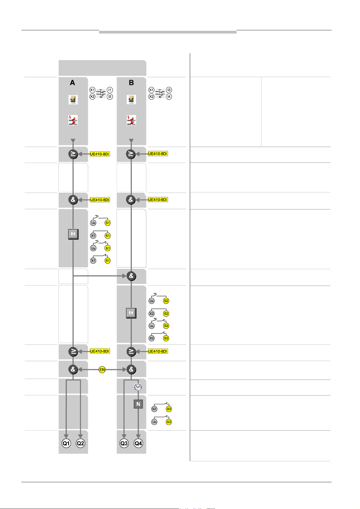
Chapter 3 Operating instructions
Inputs/
OR
Restart
Off delay
AND
AND
Restart
Product description
Flexi Classic
3.6.6 Program 6
2 linked logic paths
sensors
interlock
A
Dual-channel equivalent N/C
contacts
Cross-circuit detecting control
signals
Flexi Loop
OR with UE410-8DI — switch position 7
AND with UE410-8DI — switch position 1-6
Connecting of S1:
∂ with restart interlock Q1/Q2, without EDM
∂ without restart interlock Q1/Q2, without EDM
∂ with restart interlock Q1/ Q2, with EDM
∂ without re start interlock Q 1/Q2, with EDM
B
Dual-channel equivalent N/C
contacts
Cross-circuit detecting control
signals
Flexi Loop
interlock
Bypass
ENABLE
Retriggering
Outputs
Connecting of S2:
∂ with restart interlock Q3/ Q4, without EDM Q3
∂ without restart interlock Q3/Q4, without EDM Q3
∂ with restart interlock Q3/Q4, with EDM Q3
∂ without re start interlock Q 3/Q4, with EDM Q3
OR limited 60 s with UE410-8DI — switch position 8
Always wire ENABLE (expected 24 V DC)!
At ENABLE low Q1-Q4 are always low.
Off delay acts only on Q4
(not on UE410-xxxT0).
Connecting of S3:
with/without EDM Q4
∂ retriggering ON
∂ retriggering OFF
Undelayed OSSDs Q1-Q3
Delayable OSSD Q4
42 © SICK AG • Industrial Safety Systems • Germany • All rights reserved 8011509/YPP0/2015-10-26
Subject to change without notice
Page 43
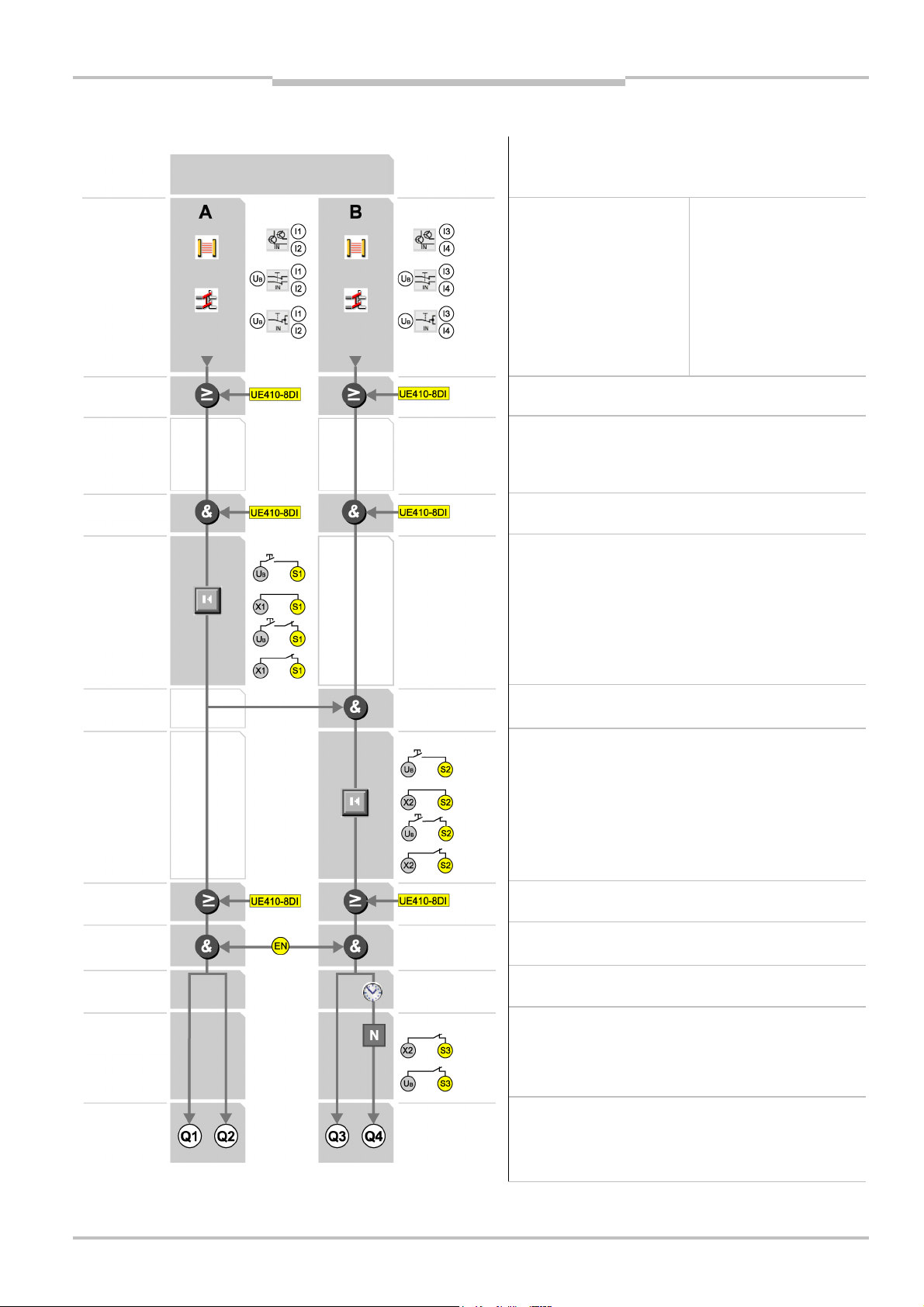
Operating instructions Chapter 3
Inputs/
OR
Restart
ENABLE
Outputs
AND
ANDRestart
Product description
Flexi Classic
3.6.7 Program 7
2 linked logic paths
sensors
interlock
A
Single-channel N/C contact
Dual-channel equivalent N/C
contact
(not cross-circuit detecting)
ESPE and sensors with
semiconductor output
OR with UE410-8DI — switch position 7
AND with UE410-8DI — switch position 1-6
Connecting of S1:
∂ with restart interlock Q1/Q2, without EDM
∂ without restart interlock Q1/Q2, without EDM
∂ with restart interlock Q1/ Q2, with EDM
∂ without re start interlock Q 1/Q2, with EDM
B
Single-channel N/C contacts
Dual-channel equivalent N/C
contact
(not cross-circuit detecting)
ESPE and sensors with
semiconductor output
interlock
Bypass
Off delay
Retriggering
Connecting of S2:
∂ with restart interlock Q3/ Q4, without EDM Q3
∂ without restart interlock Q3/Q4, without EDM Q3
∂ with restart interlock Q3/Q4, with EDM Q3
∂ without re start interlock Q 3/Q4, with EDM Q3
OR limited 60 s with UE410-8DI — switch position 8
Always wire ENABLE (expected 24 V DC)!
At ENABLE low Q1-Q4 are always low.
Off delay acts only on Q4
(not on UE410-xxxT0).
Connecting of S3:
with/without EDM Q4
∂ retriggering ON
∂ retriggering OFF
Undelayed OSSDs Q1-Q3
Delayable OSSD Q4
8011509/YPP0/2015-10-26 © SICK AG • Industrial Safety Systems • Germany • All rights reserved 43
Subject to change without notice
Page 44

Chapter 3 Operating instructions
Inputs/
OR
Restart
ENABLE
AND
AND
Restart
Retriggering
Product description
Flexi Classic
3.6.8 Program 8
2 independent logic paths
sensors
interlock
A
Single-channel N/C contact
Dual-channel equivalent N/C
contact
(not cross-circuit detecting)
ESPE and sensors with
semiconductor output
OR with UE410-8DI — switch position 7
AND with UE410-8DI — switch position 1-6
Connecting of S1:
∂ with restart interlock Q1/Q2, without EDM
∂ without restart interlock Q1/Q2, without EDM
∂ with restart interlock Q1/ Q2, with EDM
∂ without re start interlock Q 1/Q2, with EDM
B
Single-channel N/C contacts
Dual-channel equivalent N/C
contact
(not cross-circuit detecting)
ESPE and sensors with
semiconductor output
interlock
Bypass
Off delay
Outputs
Connecting of S2:
∂ with restart interlock Q3/ Q4, without EDM Q3
∂ without restart interlock Q3/Q4, without EDM Q3
∂ with restart interlock Q3/Q4, with EDM Q3
∂ without re start interlock Q 3/Q4, with EDM Q3
OR limited 60 s with UE410-8DI — switch position 8
Always wire ENABLE (expected 24 V DC)!
At ENABLE low Q1-Q4 are always low.
Off delay acts only on Q4
(not on UE410-xxxT0).
Connecting of S3:
with/without EDM Q4
∂ retriggering ON
∂ retriggering OFF
Undelayed OSSDs Q1-Q3
Delayable OSSD Q4
44 © SICK AG • Industrial Safety Systems • Germany • All rights reserved 8011509/YPP0/2015-10-26
Subject to change without notice
Page 45

Operating instructions Chapter 3
Inputs/
OR
Restart
Outputs
AND
AND
Restart
Retriggering
Product description
Flexi Classic
3.6.9 Program 9
2 linked logic paths
sensors
interlock
A
Dual-channel equivalent
N/C contacts
Cross-circuit detecting control
signals
Flexi Loop
OR with UE410-8DI — switch position 7
AND with UE410-8DI — switch position 1-6
Connecting of S1:
∂ with restart interlock Q1/Q2, without EDM
∂ without restart interlock Q1/Q2, without EDM
∂ with restart interlock Q1/ Q2, with EDM
∂ without re start interlock Q 1/Q2, with EDM
B
Single-channel N/C contacts
Dual-channel equivalent
N/C contact
(not cross-circuit detecting)
ESPE and sensors with
semiconductor output
interlock
Bypass
ENABLE
Off delay
Connecting of S2:
∂ with restart interlock Q3/ Q4, without EDM Q3
∂ without restart interlock Q3/Q4, without EDM Q3
∂ with restart interlock Q3/Q4, with EDM Q3
∂ without re start interlock Q 3/Q4, with EDM Q3
OR limited 60 s with UE410-8DI — switch position 8
Always wire ENABLE (expected 24 V DC)!
At ENABLE low Q1-Q4 are always low.
Off delay acts only on Q4
(not on UE410-xxxT0).
Connecting of S3:
with/without EDM Q4
∂ retriggering ON
∂ retriggering OFF
Undelayed OSSDs Q1-Q3
Delayable OSSD Q4
8011509/YPP0/2015-10-26 © SICK AG • Industrial Safety Systems • Germany • All rights reserved 45
Subject to change without notice
Page 46

Chapter 3 Operating instructions
Product description
Flexi Classic
3.6.10 Connection of sensors to the UE410-MU/UE410-XU
Notes
WARNING
Program Inputs of logic path A Inputs of logic path B
0 Module inactive
1
Dual-channel equivalent
N/C contact
cross-circuit detecting
synchronisation time
monitoring 1500 ms
Four-wire
cross-circuit detecting
(e.g. cross-circuit detecting
switching mats)
• The allocation of the outputs X1 to X2 to the inputs I1 to I4 depends on the selected
input circuit function.
• The functions of logic paths A and B can be set independently of each other.
Warning!
Unused inputs must be bridged as per the state shown!
= Connect the sensors (type depending on the switch position) in accordance with
Tab. 18.
X1-I1
X2-I2
X1-I1
X2-I2
Dual-channel non-isolated
semiconductors
Dual-channel N/C contact,
three-wire
Single-channel N/C contact UB-I3
UB-I3
UB-I4
UB-I3
UB-I4
UB-I4
2
Dual-channel
complementary N/C
contact
cross-circuit detecting
synchronisation time
monitoring 1500 ms
Dual-channel
complementary N/C
contact
cross-circuit detecting
synchronisation time
monitoring 1500 ms
X1-I1
X2-I2
X1-I1
X2-I2
Dual-channel non-isolated
semiconductors
Dual-channel N/C contact,
three-wire
Single-channel N/C contact UB-I3
UB-I3
UB-I4
UB-I3
UB-I4
UB-I4
46 © SICK AG • Industrial Safety Systems • Germany • All rights reserved 8011509/YPP0/2015-10-26
Subject to change without notice
Page 47

Operating instructions Chapter 3
Flexi Classic
Program Inputs of logic path A Inputs of logic path B
Product description
3
Single-channel
N/C contact
Dual-channel N/C
contact, three-wire
UB-I1
UB-I2
UB-I1
UB-I2
Muting
2 single-channel N/C contacts
or
dual-channel non-isolated
UB-I3
UB-I4
semiconductor
Dual-channel nonisolated semiconductors
3.1
Single-channel N/C
contacts/ESPE
(sensors with semiconductor output)
3.2
Single-channel N/C
contacts/IN4000
(inductive switch with
semiconductor output)
3.2
4
Two-hand control (X1-I1
N/O contact; X1-I2 N/C
UB-I1
UB-I2
X2-I2
(bridge
X1-I1)
X1-I1
(bridge
X2-I2)
X1-I1
X1-I2
Two-hand control (X1-I3 N/O
contact; X2-I4 N/C contact)
X2-I3
X2-I4
contact)
5
Dual-channel equivalent
N/C contact
X1-I1
X2-I2
2 single-channel N/O contacts,
cross-circuit detecting
X1-I3
X2-I4
cross-circuit detecting
6
Dual-channel equivalent
N/C contact
cross-circuit detecting
7
Dual-channel non-isolated
semiconductors
Dual-channel N/C contact,
three-wire
Single-channel N/C
contact
X1-I1
X2-I2
UB-I1
UB-I2
UB-I1
UB-I2
UB-I1
UB-I2
Dual-channel equivalent N/C
contact
X1-I3
X2-I4
cross-circuit detecting
Dual-channel non-isolated
semiconductors
Dual-channel N/C contact,
three-wire
UB-I3
UB-I4
UB-I3
UB-I4
Single-channel N/C contact UB-I3
UB-I4
8011509/YPP0/2015-10-26 © SICK AG • Industrial Safety Systems • Germany • All rights reserved 47
Subject to change without notice
Page 48

Chapter 3 Operating instructions
Program Inputs of logic path A Inputs of logic path B
Product description
Flexi Classic
8
Dual-channel non-isolated
semiconductors
Dual-channel N/C contact,
three-wire
Single-channel N/C
contact
9
Dual-channel equivalent
N/C contact
cross-circuit detecting
Tab. 18: Connection of sensors to the UE410-MU/UE410-XU
UB-I1
UB-I2
UB-I1
UB-I2
UB-I1
UB-I2
X1-I1
X2-I2
Dual-channel non-isolated
semiconductors
Dual-channel N/C contact,
three-wire
UB-I3
UB-I4
UB-I3
UB-I4
Single-channel N/C contact UB-I3
UB-I4
Dual-channel non-isolated
semiconductors
Dual-channel N/C contact,
three-wire
Single-channel N/C contact
UB-I3
UB-I4
UB-I3
UB-I4
UB-I3
UB-I4
48 © SICK AG • Industrial Safety Systems • Germany • All rights reserved 8011509/YPP0/2015-10-26
Subject to change without notice
Page 49
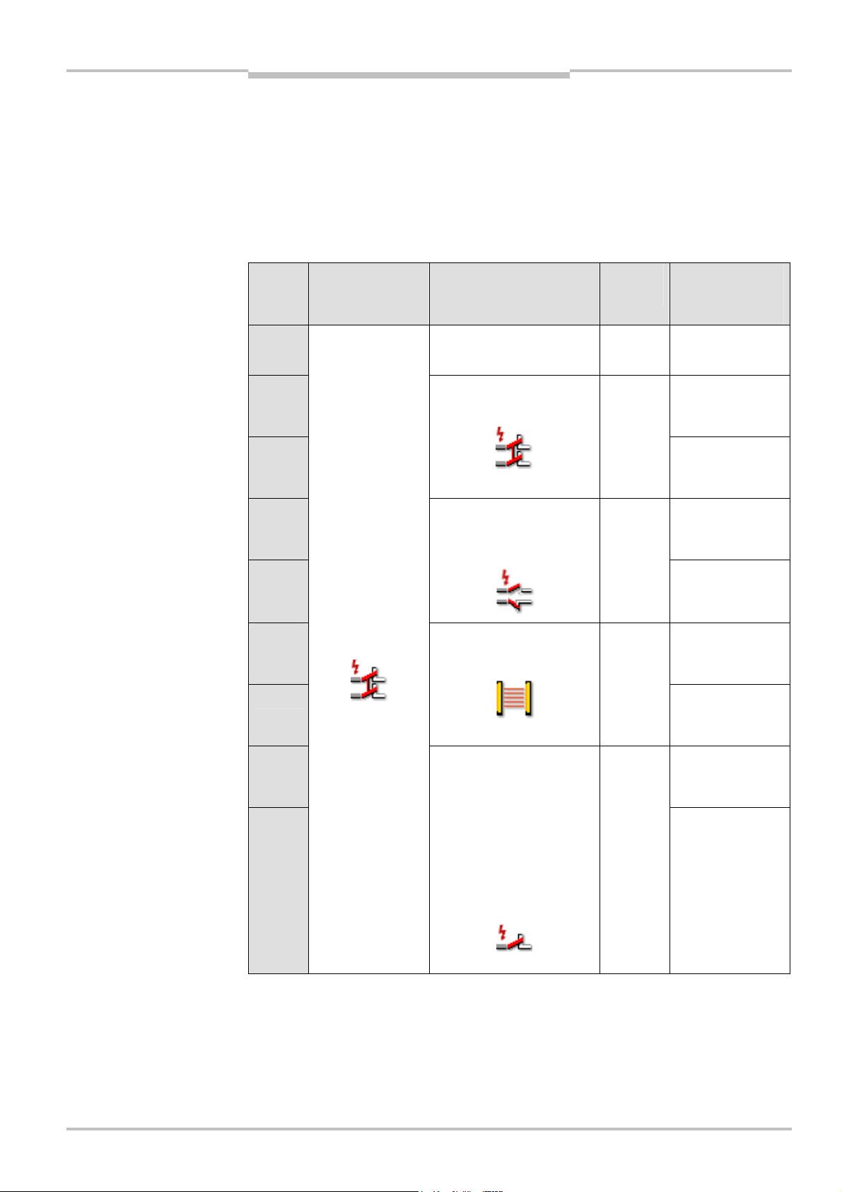
Operating instructions Chapter 3
Tab.19:
UE410
-
GU
Flexi Classic
Product description
3.7 UE410-GU programs
The UE410-GU has 9 programs that are set using the program switch.
The global emergency stop function with manual reset is active in all programs. Depending
on the program set, a local emergency stop function can also be configured with which it is
possible to choose between manual reset and automatic reset.
The selection of the program defines the type of safety sensor to be connected and the
principle of operation of the local reset. The operator logic is identical for all programs.
programs
Program
1 – – –
2 Manual
3
4 Manual
Function I1/I2
(global emergency
stop)
Function I3/I4
(local emergency stop)
Equivalent switch, crosscircuit detecting
Dual-channel N/C / N/O
contact, complementary,
Moni-
toring
I3–X1
I4–X2
I3–X1
I4–X2
Function I6
(reset of the local
emergency stop)
Automatic
cross-circuit detecting
5
Automatic
Equivalent switch,
cross-circuit
6 Manual
detecting
OSSD or untested safety
switch
I3–Ux
I4–Ux
6)
5)
Note
7
8 Manual
Single-channel N/C
contact, cross-circuit
I3–n. u.
I4–X2
Automatic
7)
detecting, e.g.
9
• emergency stop
Automatic
pushbutton
• safety switch
• testable sensors
(e.g. L41)
Switch position 0 is not permitted.
5)
A reset button for the global emergency stop must always be connected to I6. This button also acts as the
reset button for manually resetting the local emergency stop if necessary.
6)
Ux = independent 24 V supply that must be connected to the same GND connection as the power supply for
the UE410-GU.
7)
Not connected, i.e. I3 must not be connected.
8011509/YPP0/2015-10-26 © SICK AG • Industrial Safety Systems • Germany • All rights reserved 49
Subject to change without notice
Page 50

Chapter 3 Operating instructions
Inputs/
OR
Restart
AND
Restart
Product description
Flexi Classic
2 linked logic paths
sensors
interlock
A
Global emergency stop
e.g. program 6
Dual-channel equivalent N/C
contacts
Cross-circuit detecting control
signals
Flexi Loop
OR with UE4 10-8DI — switch position 7 input B
Switch position 7 input A i s not permitted, UE410-GU switches to
ERROR (configuration error).
AND with UE410-8DI — switch position 1-6
Global reset — connecting of I6:
∂ with restart interlock Q1
B
Local cut-off path
for programs see Tab. 19
e.g. program 6
Single-channel N/C contacts
Dual-channel equivalent N/C
contact ( not cross-circuit
detecting)
ESPE and sensors with
semiconductor output
interlock
Output
Local reset — connecting of I6:
∂ with restart interlock Q1
∂ only in the programs 2, 4, 6, 8
OR limited 60 s with UE410-8DI — switch position 8 input B
Switch position 8 input A i s not permitted, UE410-GU switches to
ERROR (configuration error).
50 © SICK AG • Industrial Safety Systems • Germany • All rights reserved 8011509/YPP0/2015-10-26
Subject to change without notice
Page 51

Operating instructions Chapter 3
Tab.20:
UE410
-
8DI switch
Flexi Classic
Product description
3.8 UE410-8DI input extension module
The UE410-8DI module is an input extension with 8 safe inputs.
A UE410-8DI is used to add additional inputs either to a UE410-MU, UE410-GU or UE410XU. The simultaneous use of up to UE410-8DI per UE410-MU, UE410-GU or UE410-XU is
possible.
A UE410-8DI input extension module acts exclusively on the next UE410-MU, UE410-GU or
UE410-XU module on the left in the module structure. It has two separate input groups
each with 4 inputs for connecting safe signal detectors and sensors. The UE410-8DI has a
separate switch for each input group (input A and B). The 9 positions on the rotary switch
determine the type of safety component which can be connected and with which logic (OR,
AND or Bypass) it will act on the UE410-MU, UE410-GU or UE410-XU.
The input group A of a UE410-8DI acts on the logic path A of a connected UE410-MU,
UE410-GU or UE410-XU.
The input group B of a UE410-8DI acts on the logic path B of a connected UE410-MU,
UE410-GU or UE410-XU.
Each input group consists of two input pairs. At input A, for example, this is I1/I2 and
I3/I4. Two inputs are AND-linked and form an input pair. This does not apply for switch
position 1.
positions
Switch
position
0 Selected input (A/B) is inactive — input signals are ignored.
Description
The connected single-channel sensor equipment is AND-linked to the
1
respective logic path of the UE410-MU/UE410-GU/UE410-XU modules.
Unused inputs have to be jumpered in accordance with the state logical “1”
(e.g. X4-I4, UB-I4).
The connected dual-channel sensor equipment is AND-linked to the
2-6
respective logic path of the UE410-MU/UE410-GU/UE410-XU modules.
Unused inputs have to be jumpered in accordance with the state logical “1”
(e.g. X4-I4, UB-I4).
7
The connected dual-channel sensor equipment is OR-linked to the
respective logic path of the UE410-MU/UE410-GU/UE410-XU modules.
The connected dual-channel sensor equipment is Bypass-linked to the
8
9
respective safety outputs of the UE410-MU/UE410-GU/UE410-XU modules
(time-limited OR function).
9)
Reciprocal assignment of input A/input B in order to link all 8 inputs on a
logic path.
For more informationen on this topic see section 4.12 “Grouping of subsystems” on
page 78.
8)
8)
An OR function that acts on the global cut-off path on the UE410-GU (switch position 7, input A on the
UE410-8DI) is not permitted and will result in a configuration err or (ERROR).
9)
A bypass function that acts on the global cut-off path on the UE410-GU (switch position 8, input A on the
UE410-8DI) is not permitted and will result in a configuration err or (ERROR).
8011509/YPP0/2015-10-26 © SICK AG • Industrial Safety Systems • Germany • All rights reserved 51
Subject to change without notice
Page 52

Chapter 3 Operating instructions
Tab.21:
UE410
-
8DI switch
Product description
Flexi Classic
3.8.1 AND link
The switch settings 1 to 6 of the UE410-8DI add inputs to the UE410-MU/UE410-GU/
UE410-XU modules and link them with AND logic.
If the input conditions I1-I4 and I5-I8 are logical “1”, the AND function is active and the
LED QA or QB is illuminated.
positions
Switch
position
Application Electrical configuration
0 For unused inputs –
1 • Emergency stop button
• Safety switch
• Testable sensors
2 • Emergency stop button
• Safety switch
• Switching mat (pressure-
sensitive)
• Flexi Loop
3 • Emergency stop button
• Safety switch
• Flexi Loop
4 • Safety switch
Single-channel N/C contact
Dual-channel N/C contact,
equivalent, cross-circuit
detecting
Dual-channel N/C contact,
equivalent, cross-circuit
detecting, synchronous time
monitoring 1500 ms
Dual-channel N/C / N/O
contact, complementary, crosscircuit detecting
5 • Safety switch
• RE300
6 • Emergency stop button
• Safety switch
• ESPE (e.g. C4000)
Dual-channel N/C / N/O
contact, complementary, crosscircuit detecting, synchronous
time monitoring. 1500 ms
Single-channel N/C contact
Dual-channel N/C contact,
equivalent
Dual-channel semiconductor
output
52 © SICK AG • Industrial Safety Systems • Germany • All rights reserved 8011509/YPP0/2015-10-26
Subject to change without notice
Page 53

Operating instructions Chapter 3
Tab.22:
OR link UE410
-
8DI
Tab.23:
Bypass UE410
-
8DI
Flexi Classic
Note
Product description
3.8.2 OR link
The switch position 7 of the UE410-8DI adds inputs to the UE410-MU/UE410-XU modules
and links these with OR logic.
All input pairs are AND-linked internally. For example, only if I1 and I2 are high is the OR
signal from this pair active. If the input conditions I1/I2 or I3/I4 are logical “1”, the OR
function is active and the LED QA or QB is illuminated.
OR function on the UE410-GU via UE410-8DI
On the UE410-GU the OR function is only available via the UE410-8DI input extension
module (switch position 7) and only on the local cut-off path, i.e. via input B.
An OR function that acts on the global cut-off path on the UE410-GU (switch position 7,
input A on the UE410-8DI) is not permitted and will result in a configuration error (ERROR).
Note
Switch
position
7 • Safety switch
3.8.3 Bypass
The switch position 8 of the UE410-8DI jumpers the outputs of the UE410-MU/UE410-XU
modules for the maximum duration of 60 s. The bypass is only active if I1 and I2 or I5 and
I6 are logical “1”. input pairs I3/I4 and I7/I8 do not have to be wired, they have no
function.
Bypass function on the UE410-GU via UE410-8DI
On the UE410-GU the bypass function is only available via the UE410-8DI input extension
module (switch position 8) and only on the local cut-off path, i.e. via input B.
A bypass function that acts on the global cut-off path on the UE410-GU (switch position 8,
input A on the UE410-8DI) is not permitted and will result in a configuration error (ERROR).
Application Electrical configuration
• ESPE (e.g. C4000)
Single-channel N/C contact
Dual-channel N/C contact,
equivalent
Dual-channel semiconductor
output
Switch
position
8
Bypass bypasses the safety device!
WARNING
8011509/YPP0/2015-10-26 © SICK AG • Industrial Safety Systems • Germany • All rights reserved 53
Subject to change without notice
It should only be possible to generate the bypass signal by means of a dual-channel N/O
key switch. The bypass should only be activated through a conscious act of the operator
and with a view of the hazardous area.
Application Electrical configuration
• Teach-in key-operated
switch
• Enabling switch
Dual-channel N/C contact,
equivalent, cross-circuit
detection
Page 54
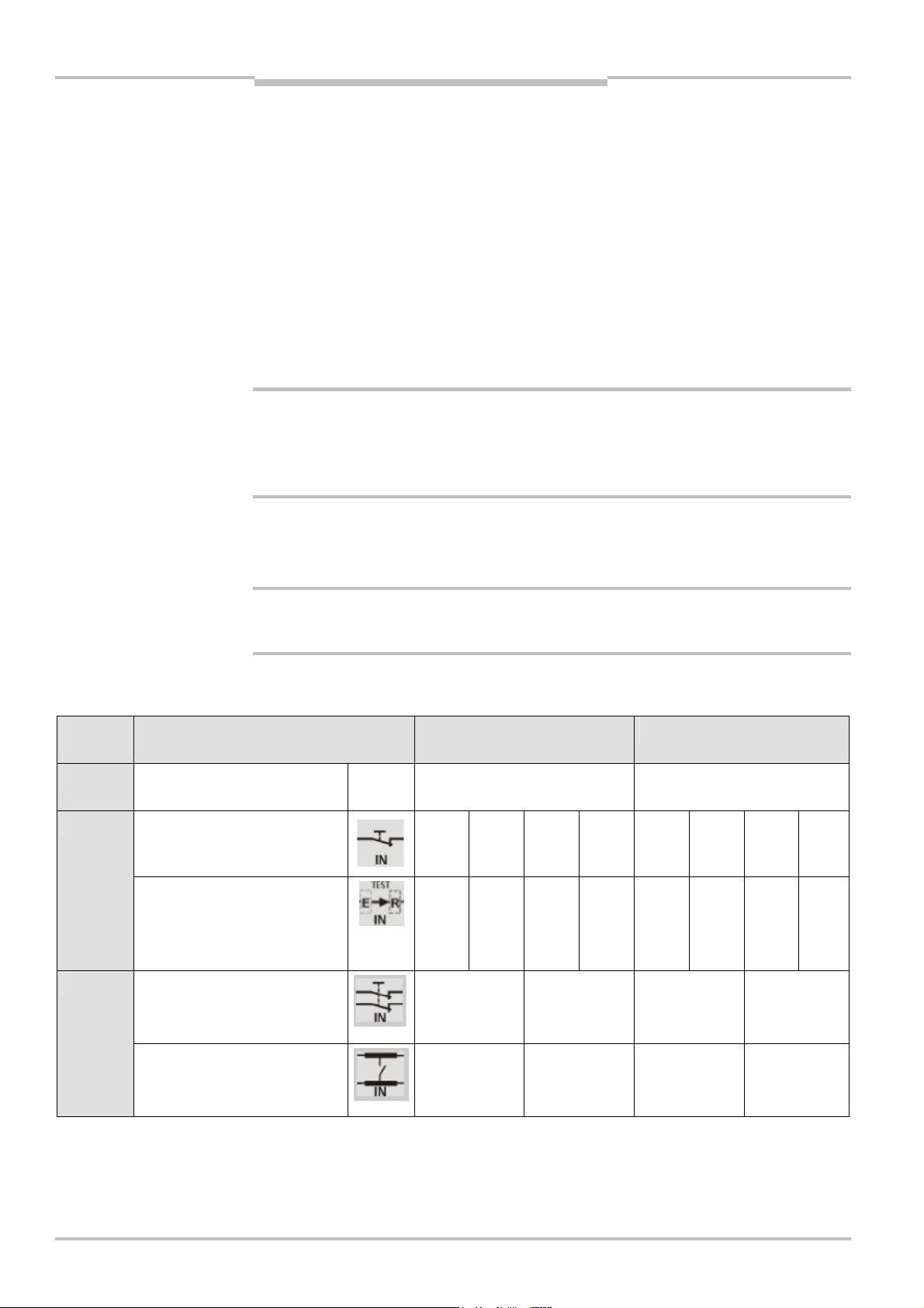
Chapter 3 Operating instructions
Note
WARNING
Product description
Flexi Classic
3.8.4 Reciprocal assignment — Mirror mode
Switch position 9:
The functionality and logical link of input B is assigned to the logic of input A. Input group A
then has 8 inputs.
Or:
The functionality and logical link of input A is assigned to the logic of input B. Input group B
then has 8 inputs.
Function 9 may only be selected for one of the two input groups respectively. Otherwise a
device error ERROR is generated and the ERR LED flashes.
3.8.5 Connection of sensors to the UE410-8DI
A UE410-8DI has two test pulse generators. This means that short-circuits between odd
(X1) and evenly (X2) numbered outputs will be detected. Short-circuits between two odd
(i.e. X1 and X3) or two evenly (i.e. X2 and X4) numbered outputs will not be detected.
Please heed this when wiring the safety sensors.
Switch
position
0
2
Notes
WARNING
All the inputs of Group A or B
are not used
AND
4 × single-channel with testing
AND
4 × single-channel with
sensors that can be tested
(ESPE)
AND
2 × dual-channel, cross-circuit
detection
• The assignment of outputs X1 to X8 to inputs I1 to I8 depends on the selected rotary
switch position.
• The functions of logic paths A and B can be set independently of each other.
When AND logic is used, unused inputs have to be jumpered in accordance with the state
logical “1” (e.g. X4-I4, UB-I4)!
= Connect the sensors (type depending on the switch position) in accordance with
Tab. 24.
Input A Input B
N.c. Terminals not connected Terminals not connected
X1-I1 X2-I2 X3-I3 X4-I4 X5-I5 X6-I6 X7-I7 X8-I81
X1-I1 X2-I2 X3-I3 X4-I4 X5-I5 X6-I6 X7-I7 X8-I8
X1-I1
X2-I2
X3-I3
X4-I4
X5-I5
X6-I6
X7-I7
X8-I8
AND
2 × dual-channel, cross-circuit
detection
X1-I1
X2-I2
X3-I3
X4-I4
X5-I5
X6-I6
X7-I7
X8-I8
54 © SICK AG • Industrial Safety Systems • Germany • All rights reserved 8011509/YPP0/2015-10-26
Subject to change without notice
Page 55

Operating instructions Chapter 3
Flexi Classic
Product description
Switch
position
3 AND
2 × dual-channel, cross-circuit
detection, synchronous time
monitoring 1500 ms
4 AND
2 × dual-channel, cross-circuit
detection
5 AND
2 × dual-channel, cross-circuit
detection, synchronous time
monitoring 1500 ms
6
AND
2 × dual-channel,
semiconductor
AND
2 × dual-channel, three-wire
AND
2 × single-channel
Input A Input B
X1-I1
X2-I2
X1-I1
X2-I2
X1-I1
X2-I2
OSSD1
OSSD2
+UB-I1
+UB-I2
+UB-I1
+UB-I2
Sensor
Sensor
-I1
-I2
X3-I3
X4-I4
X3-I3
X4-I4
X3-I3
X4-I4
OSSD1
OSSD2
+UB-I3
+UB-I4
+UB-I3
+UB-I4
Sensor
Sensor
-I3
-I4
X5-I5
X6-I6
X5-I5
X6-I6
X5-I5
X6-I6
OSSD1
OSSD2
+UB-I5
+UB-I6
+UB-I5
+UB-I6
Sensor
Sensor
-I5
-I6
X7-I7
X8-I8
X7-I7
X8-I8
X7-I7
X8-I8
OSSD1
OSSD2
+UB-I7
+UB-I8
+UB-I7
+UB-I8
Sensor
Sensor
-I7
-I8
7
OR
2 × dual-channel,
OSSD1
OSSD2
Sensor
Sensor
-I1
-I2
semiconductor
OR
2 × dual-channel,
+UB-I1
+UB-I2
three-wire
OR
2 × single-channel
8 Bypass
1 × dual-channel, cross-circuit
+UB-I1
+UB-I2
X1-I1
X2-I2
detection
9 Input supplement
With AND logic, unused inputs must be bridged to logical “1” (e.g. X4-I4, UB-I4)!
Tab. 24: Connection of sensors to the UE410-8DI
Function as for input B Function as for input A
–
OSSD1
OSSD2
+UB-I3
+UB-I4
+UB-I3
+UB-I4
I3 n.c.
I4 n.c.
Sensor
Sensor
-I3
-I4
OSSD1
OSSD2
+UB-I5
+UB-I6
+UB-I5
+UB-I6
X5-I5
X6-I6
Sensor
Sensor
-I5
-I6
OSSD1
OSSD2
+UB-I7
+UB-I8
+UB-I7
+UB-I8
I7 n.c.
I8 n.c.
Sensor
Sensor
-I7
-I8
8011509/YPP0/2015-10-26 © SICK AG • Industrial Safety Systems • Germany • All rights reserved 55
Subject to change without notice
Page 56

Chapter 3 Operating instructions
Fig.12:
UE410
-
8DI controls
Tab.25:
UE410
-
8DI LED
Tab.26:
UE410
-
8DI
Program switch input A
Program switch input B
Product description
Flexi Classic
3.8.6 Controls and status indicators
and status indicators
indications
LED indicators Meaning
PWR (green) Supply voltage via safety bus is present.
I1-I8 (green) Logical “1” is applied at the corresponding input.
I1, I2 flash in phase Cross-circuit between I1, I2
I3, I4 flash in phase Cross-circuit between I3, I4
I5, I6 flash in phase
Cross-circuit between I5, I6 or modules with different revision
code (see section 10.2 “Replacement of a module” on
page 93)
I7, I8 flash in phase
Cross-circuit between I7, I8 or modules with different revision
code (see section 10.2 “Replacement of a module” on
page 93)
I1, I2 flash out of phase Process error at I1, I2
I3, I4 flash out of phase Process error at I3, I4
I5, I6 flash out of phase Process error at I5, I6
I7, I8 flash out of phase Process error at I7, I8
I1 or I2 flashing Synchronous time (1500 ms) exceeded
I3 or I4 flashing Synchronous time (1500 ms) exceeded
I5 or I6 flashing Synchronous time (1500 ms) exceeded
operating elements
56 © SICK AG • Industrial Safety Systems • Germany • All rights reserved 8011509/YPP0/2015-10-26
I7 or I8 flashing Synchronous time (1500 ms) exceeded
QA (green) Input conditions input A of inputs I1 to I4 are fulfilled.
QB (green) Input conditions input B of inputs I5 to I8 are fulfilled.
ERR (red flashing)
Erroneous operational status on this module, see chapter 10
“Diagnostics” on page 93
ERR (red)
Erroneous operational status on the whole system (the error
is on another module), see chapter 10 “Diagnostics” on
page 93
Switch/button Function
INPUT A
INPUT B
10-step rotary switches for setting an input circuit function
(input group A or B)
Subject to change without notice
Page 57

Operating instructions Chapter 3
Tab.27:
Termina
ls
Fig.13:
Internal structure
Flexi Classic
Product description
3.8.7 Inputs and outputs
UE410-8DI
Assignment Description
I1-I4 Inputs for the connection of signal detectors or sensors (input A)
X1-X4
Test outputs: cross-circuit detecting control signals for controlling
sensors of the module (input A)
I5-I8 Inputs for the connection of signal detectors or sensors (input B)
X5-X8
Test outputs: cross-circuit detecting control signals for controlling
sensors of the module (input B)
For more informationen on this topic see section 4.12 “Grouping of subsystems” on
page 78.
3.9 UE410-2RO/UE410-4RO output modules
The UE410-2RO/UE410-4RO output modules make dual-channel contact-based outputs
with positively guided relay contacts available.
The output modules may only be operated in a system combination with a UE410-MU/XU.
A maximum of four UE410-4RO or eight UE410-2RO can be connected to a Flexi Classic
system.
The slot of an output module in the Flexi Classic system is on the end of the safety
assembly.
UE410-2RO
3.9.1 Output module UE410-2RO
The UE410-2RO has one control input (B1). This input controls two internal relays and
forms a redundant shutdown path comprising:
• two “safe enable current paths” (13/14, 23/24), dual-channel and floating,
• one “safe enable current path” (Y14), dual-channel and not floating,
• one “external device monitoring feedback circuit” (Y1/Y2), dual-channel and floating.
8011509/YPP0/2015-10-26 © SICK AG • Industrial Safety Systems • Germany • All rights reserved 57
Subject to change without notice
Page 58

Chapter 3 Operating instructions
Fig.14:
Internal
structure
Product description
Flexi Classic
3.9.2 Output module UE410-4RO
The UE410-4RO has two control inputs (B1, B2). These inputs control two-by-two internal
relays that form two independent redundant shutdown paths.
Control input (B1) operates two internal relays and forms one redundant shutdown path
comprising:
• two “safe enable current paths” (13/14, 23/24), dual-channel and floating,
• one “safe enable current path” (Y14), dual-channel and not floating,
• one “external device monitoring feedback circuit” (Y1/Y2), dual-channel and floating.
Control input (B2) operates two internal relays and forms one redundant shutdown path
comprising:
• two “safe enable current paths” (33/34, 43/44), dual-channel and floating,
• one “safe enable current path” (Y24), dual-channel and not floating,
• one “external device monitoring feedback circuit” (Y3/Y4), dual-channel and floating.
The UE410-4RO therefore has twice the functionality of an UE410-2RO.
UE410-4RO
58 © SICK AG • Industrial Safety Systems • Germany • All rights reserved 8011509/YPP0/2015-10-26
Subject to change without notice
Page 59
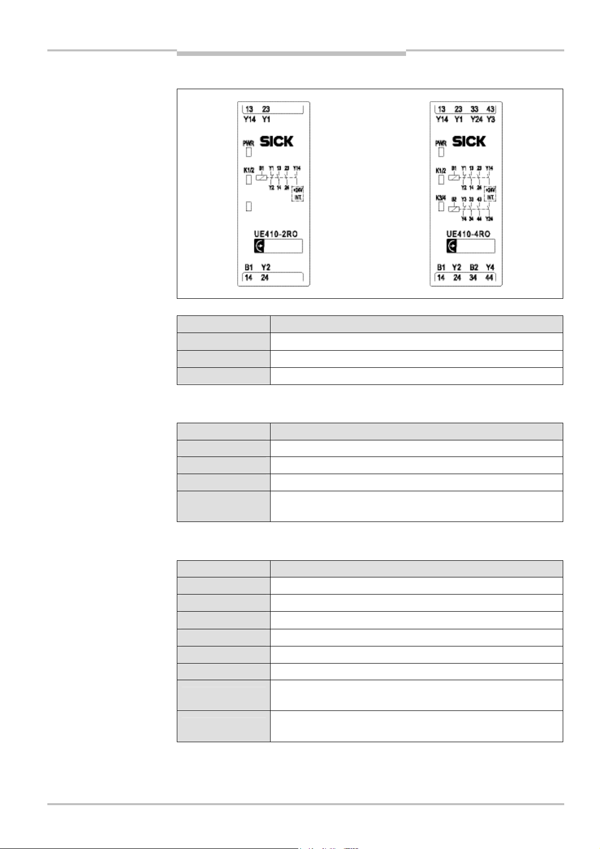
Operating instructions Chapter 3
Fig.15:
Tab.28:
Tab.29:
Termin als
Tab.30:
Termin als
Flexi Classic
Product description
3.9.3 Controls and status indicators
UE410-2RO/UE410-4RO
controls and status indicators
UE410-2RO/UE410-4RO
indicators
UE410-2RO
UE410-4RO
LED indicators Meaning
PWR (green) Supply voltage via safety bus is present
K1/2 (green) Relay K1/K2 — safety contacts closed
K3/4 (green) Relay K3/K4 — safety contacts closed
3.9.4 UE410-2RO inputs and outputs
Assignment Description
B1 Connecting relay K1/K2
13/14 and 23/24 Safety contacts for switch-off circuit K1/K2
Y1/Y2 Feedback circuit external device monitoring (EDM), N/C contact
Y14
N/O safety contact K1/K2, current-limited,
see chapter 11 “Technical specifications” on page 96
3.9.5 UE410-4RO inputs and outputs
Assignment Description
B1 Connecting relay K1/K2
B2 Connecting relay K3/K4
13/14 and 23/24 Safety contacts for switch-off circuit outputs K1/K2
33/34 and 43/44 Safety contacts for switch-off circuit outputs K3/K4
Y1/Y2 Feedback EDM K1/K2, N/C contact
Y3/Y4 Feedback EDM K3/K4, N/C contact
Y14
Y24
8011509/YPP0/2015-10-26 © SICK AG • Industrial Safety Systems • Germany • All rights reserved 59
Subject to change without notice
N/O safety contact K1/K2, current-limited,
see chapter 11 “Technical specifications” on page 96
N/O safety contact K3/K4, current-limited,
see chapter 11 “Technical specifications” on page 96
Page 60

Special applications and
Chapter 4 Operating instructions
functions
Flexi Classic
4 Special applications and functions
This chapter describes the special applications and functions that can be implemented
with a Flexi Classic system.
These are the connection and configuration of the safety sensors and the settings at the
Flexi Classic system:
• RE300 magnetic safety switch
• IN4000 inductive safety switch
• connection of testable single-beam photoelectric safety switches
• two-hand operation/jog mode
• OR function
• muting function
• bypass function
• connecting of S1, S2, S3
– restart interlock
– external device monitoring (EDM)
• retriggering
• grouping of subsystems
• ENABLE input
60 © SICK AG • Industrial Safety Systems • Germany • All rights reserved 8011509/YPP0/2015-10-26
Subject to change without notice
Page 61

Special applications and
Fig.16:
Connection of a
Operating instructions Chapter 4
Flexi Classic
functions
4.1 RE300 magnetic safety switch
RE300 magnetic safety sensors can be connected directly to the inputs of the
UE410-MU/UE410-GU/UE410-XU as well as UE410-8DI units. Up to eight RE300 can be
connected in series.
The necessary test signals for the RE300 switch are only generated in program 2 on the
UE410-MU/UE410-XU and in switch position 5 on the UE410-8DI. They comply with the
requirements for an application up to PL e according to EN ISO 13 849-1.
An RE300 can only be connected to the local cut-off path on I3 and I4 on the UE410-GU in
program 4 or 5. The necessary test signals (X1/X2) for the magnetic safety switch RE300
meet the requirements for applications up to PL e as per EN ISO 13 849-1.
Pay attention to the safety notes for the RE300 switch.
WARNING
RE300 to the UE410-MU/XU
Notes
• If RE300 sensors are cascaded, these have to be tested/activated regularly (for
example opening and closing of the protective doors connected to the sensors).
• Cascading of several RE300 sensors is limited by the line resistance (refer to the
operating instructions of the RE300 for further information).
• If RE300 sensors (N/C / N/O contacts) are connected, the unused input pairs have to
be connected to simulate a logical “1” input correspondingly at the UE410-8DI. The oddnumbered inputs/test outputs have to be jumpered respectively (for example I1-X1), the
even-numbered inputs/test outputs are not interconnected (for example I2-X2).
8011509/YPP0/2015-10-26 © SICK AG • Industrial Safety Systems • Germany • All rights reserved 61
Subject to change without notice
Page 62

Special applications and
Fig.17:
Connection of an
Fig.18:
Connection of two
Chapter 4 Operating instructions
Note
IN4000
functions
Flexi Classic
4.2 IN4000 inductive safety switch
IN4000 inductive safety sensors can be connected directly to the inputs of the
UE410-MU/UE410-XU units. The required test signals for the sensors are generated in the
program 3.2 of the UE410-MU/UE410-XU.
Up to nine safety sensors can be cascaded per input.
Inductive safety switches IN4000 cannot be connected to a UE410-GU.
Connection:
A safety sensor/cascade is connected to the input I1 and test output X1.
Further information is available in the IN4000 operating instructions.
IN4000
Note
Input I2 and test output X2 have to be jumpered. Terminal S2 may not be interconnected.
A selection of the IN4000 safety sensors is available in section 12.2 “Accessories/spare
parts” on page 115.
62 © SICK AG • Industrial Safety Systems • Germany • All rights reserved 8011509/YPP0/2015-10-26
Subject to change without notice
Page 63

Special applications and
Operating instructions Chapter 4
Flexi Classic
Notes
functions
4.3 Testable single-beam photoelectric safety switches
Testable single-beam photoelectric safety switches can be connected directly to the inputs
of the UE410-MU/UE410-GU/UE410-XU as well as UE410-8DI units.
• For category 2 testable photoelectric safety switches (e.g. L21) the response time of the
respective program applies.
• For category 4 testable photoelectric safety switches (e.g. L41), the response time is
calculated from the response time of the program plus the test period of the program.
• You can find the response times of the programs in chapter 11 “Technical specifica-
tions” on page 96.
The required test signals at X2 for the sensors are generated in program 3.2 of the
UE410-MU/UE410-XU.
The required test signals are generated on X2 in programs 8 and 9 on the UE410-GU.
In switch position 1 of the UE410-8DI the required test signals are generated at outputs
X1 to X8.
Up to 4 testable single-beam photoelectric switches can be cascaded per input. This
means, at the modules UE410-MU/UE410-GU/UE410-XU with one input (I2) each
respectively, at the UE410-8DI with inputs I1 to I8.
A selection of the testable single-beam photoelectric safety switches is available in
section 12.2 “Accessories/spare parts” on page 115.
WARNING
Note
Ensure protected laying of the connection cables!
If cascades are used, protected separate laying of the connection cables must be ensured.
Connection to UE410-MU/UE410-XU
A testable single-beam photoelectric safety switch/cascade uses the input I2 and test
output X2.
Connection to UE410-GU
A testable single-beam photoelectric safety switch/cascade uses the input I4 and test
output X2.
Connection to UE410-8DI
A testable single-beam photoelectric safety switch/cascade uses the inputs and test
outputs that belong together (for example I1/X1 to I8/X8).
• UE410-MU/UE410-XU:
Input I1 and test output X1 have to be jumpered. Terminal S2 may not be
interconnected.
• UE410-8DI:
The unused inputs have to be jumpered to the corresponding test outputs (for example
the free inputs I2/X2 to I8/X8).
8011509/YPP0/2015-10-26 © SICK AG • Industrial Safety Systems • Germany • All rights reserved 63
Subject to change without notice
Page 64

Special applications and
Fig.19:
Mounting to avoi
d
Chapter 4 Operating instructions
functions
Flexi Classic
Ensuring the protective function when a Flexi Classic system with single-beam
photoelectric safety switches is used
• Single-beam photoelectric safety switches may only be used as access protection in
accordance with EN ISO 13 855. Usage as finger and hand protection is not permissible.
• Interference beams (for example, direct/indirect sun irradiation, remote controls) are to
be prevented since they can reduce the availability of single-beam photoelectric safety
switches.
• The number of beams of the sender and receiver as well as the distance between the
beams must agree.
Mutual influence of single-beam photoelectric safety switches
• If several pairs of single-beam photoelectric safety switches are used, it is imperative
that the aperture angle of the sensors is observed to avoid the possibility of mutual
interference.
• If the senders are only mounted on one side, the light beams may not overlap on the
receiver side, i.e. the light beam of one sender may not reach two receivers.
• If the senders and receivers are mounted alternately, ensure that the light beam of
sender S1 cannot be received by receiver R3 and that the light beam of sender S3
cannot be received by receiver R1.
mutual optical influence
Mutual optical influence between cascades must be excluded.
Reflective surfaces that exist within the sending and receiving cones, placed or mounted
there can cause incorrect reflection and therefore non-detection of an object or a person.
All reflective surfaces and objects (for example material bins) must therefore be located at
a minimum distance (a) rotational-symmetrically around the optical axis between the
sender and receiver.
64 © SICK AG • Industrial Safety Systems • Germany • All rights reserved 8011509/YPP0/2015-10-26
Subject to change without notice
Page 65

Special applications and
Fig.20:
Minimum di
stance
alignment
Fig.21:
Minimum distance
Operating instructions Chapter 4
Flexi Classic
(a) to reflective surfaces,
correct mounting and
functions
S = Sender R = Receiver
D = Distance sender-receiver a = Minimum distance from reflective surfaces
1 = Limit of the hazardous area 3 = Direction of access to the hazardous area
2 = Reflective surface 4 = Optical axis
(a) as a factor of the distance
D for testable single-beam
photoelectric safety switches
The minimum distance (a) to reflective surfaces for single-beam photoelectric safety
switches with a field of view of 10° is calculated as follows:
• If the distance D = 3 m, the minimum distance a = 260 mm.
• If the distance D > 3 m, the minimum distance (a) is calculated using the following
equation:
a (mm) = 88.2 × D × 10³ (m)
8011509/YPP0/2015-10-26 © SICK AG • Industrial Safety Systems • Germany • All rights reserved 65
Subject to change without notice
Example:
Distance D between the sender and receiver amounts to 28 m.
With the corresponding value entered:
a (mm) = 88.2 × 28 m × 10³ = 2469.6 mm
The minimum distance (a) to the reflective surface has to amount to 2469.6 mm in this
example.
Page 66

Special applications and
Chapter 4 Operating instructions
Note
functions
Flexi Classic
4.4 Two-hand operation/jog mode
The two-hand operation function in accordance with type IIIC can be set in program 4 of
the UE410-MU/UE410-XU:
• Two pairs of complementary inputs (N/O / N/C contact pairs of both two-hand buttons)
are monitored.
• A valid input signal is only generated if the ON state (H/L level) exists at both inputs
within a period of 0.5 s (synchronous change, both two-hand buttons pressed) and if
both were in the OFF state (L/H level) beforehand.
In Program 5 at the main module UE410-MU the logic path B can monitor normal two-hand
operation (synchronous pressing of two pushbuttons within 0.5 s program 5.1), or twohand operation in jog mode (program 5.2), for example for traversing movements. Twohand operation in jog mode allows feeding or setting-up procedures.
The two-hand operation function in accordance with type IIIA can be set in program 5.1 of
the UE410-MU/UE410-XU:
• Two equivalent inputs (N/O contacts of both two-hand buttons) are monitored.
• A valid input signal is only generated if the ON state (H level) exists at both inputs within
a period of 0.5 s (synchronous change, both two-hand buttons pressed) and if both
were in the OFF state (L level) beforehand.
The jog operation function can be set in program 5.2 of the UE410-MU/XU:
• The evaluation in jog mode corresponds to two-hand operation IIIA with the difference
that the ON signal is limited to a duration of 5 s.
In the case of two-hand operation in jog mode an output signal is only generated as long
as both actuating parts are pressed. In jog mode, the duration for which the safety outputs
Q3/Q4 are on is limited to 5 s.
When the two actuating parts are released, the time is reset. Renewed activation of the
two actuation parts is possible.
In order to activate jog mode, terminal S2 remains unused. For two-hand applications,
S2 is jumpered with the supply voltage +UB.
It is not impossible to implement two-hand applications using a UE410-GU.
66 © SICK AG • Industrial Safety Systems • Germany • All rights reserved 8011509/YPP0/2015-10-26
Subject to change without notice
Page 67

Special applications and
Operating instructions Chapter 4
Flexi Classic
functions
4.5 OR function
Note
WARNING
Note
The OR function can be implemented at the UE410-MU/UE410-XU modules (switch
positions 1 and 2) or by an input extension module UE410-8DI (switch position 7).
Switch the machine to a safe state when using the OR function!
As long as the OR function is active, the outputs of the main module do not switch off. You
must ensure that while the OR function is being used, for example for the set-up mode,
other protective measures, e.g. the safe set-up mode of the machine, are activated so that
there is no danger to persons or parts of the machine while the OR function is being used.
A logic path A/B can be muted by using an OR signal. Thus, for example, a safety function
can be muted in set-up mode by means of an enabling switch. An OR link of two safety
functions is also possible.
The OR function does not have a time limit.
OR function with input extension module
All the programs of the main module offer the possibility of linking signals of the OR function at the UE410-8DI input extension modules to the input signals of the UE410-MU/
UE410-XU by means of a logical OR (also refer to section 3.8.2 “OR link” on page 53).
OR function on the UE410-MU/UE410-XU
The OR function can be implemented in the programs 1 and 2. I1/I2 is linked to I3/I4 OR.
OR function on the UE410-GU via UE410-8DI
On the UE410-GU the OR function is only available via the UE410-8DI input expansion module (switch position 7) and only on the local cut-off path, i.e. via input B.
An OR function that acts on the global cut-off path on the UE410-GU (switch position 7,
input A on the UE410-8DI) is not permitted and will result in a configuration error (ERROR).
8011509/YPP0/2015-10-26 © SICK AG • Industrial Safety Systems • Germany • All rights reserved 67
Subject to change without notice
Page 68

Special applications and
Fig.22:
Safety on mounting
Ensure that muting cannot be u
nintentionally triggered
Chapter 4 Operating instructions
Note
WARNING
functions
Flexi Classic
4.6 Muting function
Muting overrides the protective effect of a safety device temporarily. This means that
material can be transported to or from a machine or system without the working process
having to be interrupted.
In the case of muting additional sensor signals are used to differentiate between humans
and material. To this purpose an evaluation unit (for example the Flexi Classic modular
safety controller) evaluates the signals from external sensors logically and, if the muting
condition is valid, mutes the protective device so that the material to be transported can
pass the protective device. As soon as anything except the material enters the hazardous
area, the working process is interrupted.
It is not possible to implement muting applications using the UE410-GU.
Pay attention to the following safety notes!
• Muting is only allowed to be activated during the period when the material to be transported (e.g. on a pallet) blocks the access to the hazardous area.
• Muting must be triggered by at least two independently wired signals (e.g. from muting
sensors) and must not depend entirely on software signals (for instance from a PLC).
• Muting must be removed immediately as soon as the material to be transported no
longer blocks the access to the dangerous movement so that the protective device is
once more effective.
• The material to be transported must be detected over its entire length, i.e. there must
be no interruption in the output signals.
• Always position the sensors so that the minimum distance to the protective device is
observed!
• Prevent the unintentional triggering of muting by a person by mounting the sensors
appropriately!
the muting sensors
Note
by a person!
Always mount the muting lamp where it can be clearly seen!
The muting lamp must be clearly visible from all sides of the hazardous area and for the
system operator.
68 © SICK AG • Industrial Safety Systems • Germany • All rights reserved 8011509/YPP0/2015-10-26
Subject to change without notice
Page 69

Special applications and
Fig.23:
Schematic layout
A1
Hazardous area
A2
ESPE
Material
Means of tran
sport
Operating instructions Chapter 4
Flexi Classic
functions
4.6.1 Muting with two sensors
0 1 2
In the example, the material moves from left to right on a conveyor belt 0. As soon as the
muting sensors A1 and A2 are activated 1, the protection provided by the ESPE protective
device is muted and the material can move into the hazardous area. As soon as the
muting sensors are clear again 2, the protection provided by the protective device is reactivated.
4.6.2 Muting cycle
The muting cycle is the defined sequence of all processes that take place during muting.
The cycle starts when the first muting sensor is activated. The cycle ends when the last
muting sensor returns to its initial state (e.g. clear light path for optical sensors). Only then
is it possible to activate muting again.
Material can be transported several times during a muting cycle, if the muting condition is
maintained continuously, i.e. at least one pair of sensors remains activated continuously.
4.6.3 Muting sensors
Muting sensors detect material and supply the necessary signals as required by an evaluation unit (e.g. the Flexi Classic modular safety controller.) If the muting conditions are
met, the evaluation unit can mute the protective device based on the sensor signals.
Sensor signals can be generated by the following external sensors:
• optical sensors
• inductive sensors
• mechanical switches
• controller signals
SICK muting sensors
An overview of the SICK muting sensors is available in the section 4.8 “SICK muting
sensors” on page 73.
8011509/YPP0/2015-10-26 © SICK AG • Industrial Safety Systems • Germany • All rights reserved 69
Subject to change without notice
Page 70

Special applications and
Fig.24:
Detection of material
Fig.25:
Minimum distance,
Fig.26:
Principle of operation
Material
Muting sensor
Means of transport
Transport level
v
S
Hazardous area
ESPE
Detection zone
Background
Sensor
Material is
Material is not
Chapter 4 Operating instructions
WARNING
during muting
Note
functions
Flexi Classic
4.7 Placement of muting sensors
Pay attention to the following notes on the placement of the muting sensors!
= Always position the muting sensors such that only the material is detected and not the
means of transport (pallet or vehicle).
= Always position the muting sensors such that material can pass unhindered, but people
are reliably detected.
= Always position the muting sensors such that, on the detection of the material 0, a
minimum distance to the light beams on the ESPE 1 is maintained.
The minimum distance provides the processing time necessary until muting is activated.
material detection to the
ESPE on muting
of sensors with background
suppression
1
0
How to calculate the minimum distance:
S ″ v × 61 ms
Where …
S = minimum distance (mm)
v = velocity of the material (e.g. of the conveyor) (m/s)
= Use optical sensors with background suppression. These detect material only up to a
specific distance. Objects that are further away than the material to be detected are not
detected.
70 © SICK AG • Industrial Safety Systems • Germany • All rights reserved 8011509/YPP0/2015-10-26
detected
detected
Subject to change without notice
Page 71

Special applications and
Fig.27:
Muting with two
Tab.31:
Conditions for
ESPE
A1A2S3S
S
Hazardous area
Operating instructions Chapter 4
Flexi Classic
functions
4.7.1 Muting with two sensors (a sensor pair), crossed placement
sensors, crossed placement
muting with two sensors,
crossed placement
2
1
0
In the example, the material moves from left to right or, alternatively, from right to left. As
soon as the muting sensors A1 and A2 are activated, the protection provided by the protective device (ESPE) is muted.
The following requirements must be met:
Condition Description
A1 & A2 Muting applies as long as this condition is met.
Notes
How to calculate the distance:
S1″ v × 61 ms
Where …
S1 = minimum distance between the light beams of the ESPE and the detection by the
muting sensors (mm)
v = velocity of the material (e.g. of the conveyor) (m/s)
• The material can flow in both directions.
• In order for materials to be conveyed in both directions, place the intersection of the
muting sensors 0 exactly on the course of the light beams of the ESPE. In order for
material to be conveyed in one direction only, place the intersection behind the light
beams of the ESPE seen from the conveyor direction.
• This placement is suitable for through-beam photoelectric switches and photoelectric
reflex switches.
8011509/YPP0/2015-10-26 © SICK AG • Industrial Safety Systems • Germany • All rights reserved 71
Subject to change without notice
Page 72

Special applications and
Fig.28:
Simulated 4
-
sensor
ESPE
S
S1S
Hazardous area
A1A2B1
B2
Chapter 4 Operating instructions
muting
functions
Flexi Classic
4.7.2 4-sensor muting, sequential layout
3
2
In the example, the material moves from left to right. As soon as the muting sensors A1 &
A2 are activated, the protection provided by the protective device (ESPE) is muted. The
protection remains muted until one of the sensors in the muting sensor pair B1 & B2 is
clear again.
WARNING
4.7.3 Muting with UE410-MU/UE410-XU
A simple muting function can be implemented at the UE410-MU/UE410-XU modules
(programs 3.1 and 3.2) by using inputs I3 and I4 for the muting sensors. Inputs I3 and I4
are AND-linked to each other and mute the safety sensor equipment connected to I1/I2.
A muting lamp can be connected to output Q3.
Features of the muting function for UE410-MU/UE410-XU:
• The outputs on the muting sensors must be “0” on powering up the Flexi Classic, otherwise a process error will be generated and the system will generate ERROR.
• Muting duration indefinite
• Switching behaviour of the muting sensors is not limited in time.
• Direction independent muting
• Inputs I3/I4 for muting sensors can be “1” simultaneously.
• The muting lamp is not current monitored and has two functions:
– Muting lamp ON continuously, then muting is active,
– Muting lamp flashes at 1 Hz, then the Reset required is active.
Muting with 4 sensors:
• With this 4-sensor muting two muting sensors each are connected to one input of the
UE410-MU/UE410-XU. Take into account that the muting sensors A1/B2 and A2/B1
are combined respectively.
• Only “high-side”-switching sensors may be used for 4-sensor muting. Thereby it has to
be ensured that a “high” always overwrites a “low”. This type of muting may only be
used after thorough risk analysis/error analysis.
72 © SICK AG • Industrial Safety Systems • Germany • All rights reserved 8011509/YPP0/2015-10-26
Subject to change without notice
Page 73

Special applications and
Tab.32:
Selection of the
Operating instructions Chapter 4
Flexi Classic
functions
4.8 SICK muting sensors
optical SICK muting sensors
Notes
Sensor Type Switching output Q type
Photoelectric proximity
switch
Photoelectric reflex switch
Through-beam photoelectric
switch
For the selection and settings for the SICK optical muting sensors in muting applications,
the following applies:
• The outputs must be PNP switching.
• Other type series are possible.
WT24-2
WT27-3
WT260
WL23-2
WL27-3
WL260
WL12-3
WL14-2
WL18-3
WS/WE24-2
WS/WE27-3
WS260/WE260
Light switching
Dark switching
Dark switching
8011509/YPP0/2015-10-26 © SICK AG • Industrial Safety Systems • Germany • All rights reserved 73
Subject to change without notice
Page 74

Special applications and
Chapter 4 Operating instructions
Notes
WARNING
functions
Flexi Classic
4.9 Bypass
The bypass function bypasses the logic paths A/B in the UE410-MU/UE410-XU or the logic
path B in the UE410-GU and forces their safety outputs to logical “1” for 60 s. The bypass
function overrides the logic paths A/B in the UE410-MU/UE410-XU and forces the corresponding safety outputs to logical “1” for 60 s. The bypass function can be implemented via
a UE410-8DI input extension module (switch position 8).
The bypass signal is limited to a duration of 60 s. After the period has expired, bypass operation can be activated again after deactivation.
• On the UE410-GU the bypass function can only be implemented on the local cut-off path
via input B.
• A bypass function on the UE410-GU that acts on the global cut-off path (input A) is not
permitted and will result in a configuration error (ERROR).
Ensure that there is no danger during bypass operation!
As long as the bypass function is active, the safety outputs of the UE410-MU/UE410-GU/
UE410-XU modules are activated. You have to ensure that there is no danger to persons or
parts of the machine or system during bypass operation.
WARNING
Notes
The bypass function may only be activated by a key-operated switch with an automatic
reset and two levels or by two input signals that are independent of each other, e.g. two
position switches.
Check the connected key-operated pushbutton for bypass regularly!
= Using organisational measures, ensure that the key-operated pushbutton for bypass is
actuated once after a certain interval. This is necessary so that the Flexi Classic can
identify an error condition of the key-operated pushbutton for bypass or an error condition in its connection cable that occurs up until then. The interval is to be defined to suit
the specific case dependant on the application.
= Constantly check in the operating mode in which you have configured the bypass active
whether the bypass function can be activated and deactivated.
• It must be possible to view the entire hazardous point when pressing the key-operated
pushbutton for bypass.
• It may not be possible to actuate the key-operated pushbutton for bypass in the hazardous area.
• The safety controller ends the bypass automatically when an error occurs.
74 © SICK AG • Industrial Safety Systems • Germany • All rights reserved 8011509/YPP0/2015-10-26
Subject to change without notice
Page 75

Special applications and
Tab.33:
EDM by means
Tab.34:
EDM by means
Operating instructions Chapter 4
Flexi Classic
Note
functions
4.10 Connecting S1, S2, S3
Three control inputs S1, S2, and S3 are available for the configuration of the control circuit
functions (restart interlock, retriggering, EDM) at the UE410-MU/UE410-XU modules.
No control inputs are available on the UE410-GU.
4.10.1 Operation with restart interlock
In the case of operation with a restart interlock the reset button is connected to the respective input (S1/S2). The required starting condition for cancelling the restart interlock
is only fulfilled, when the reset button is pressed and released again and the feedback
circuit is closed.
4.10.2 Operation without restart interlock
The outputs are activated as soon as the input conditions of the safety sensors have the
value of logical “1”. A reset button is not required.
4.10.3 Operation with external device monitoring (EDM)
of S1
of S2
The static EDM monitors whether the controlled contactors have dropped out during resetting. The EDM is included in the feedback circuits S1, S2 and S3 in accordance with the
set program.
S1Connecting
Without EDM With EDM
Manual reset (with restart
interlock)
Automatic reset (without
restart interlock)
S2Connecting
Without EDM With EDM
Manual reset (with restart
interlock)
8011509/YPP0/2015-10-26 © SICK AG • Industrial Safety Systems • Germany • All rights reserved 75
Subject to change without notice
Automatic reset (without
restart interlock)
Page 76

Special applications and
Tab.35:
Retriggering time
Fig.29:
Retriggering ON,
Fig.30:
Retriggering OFF,
Fig.31:
Retriggering OFF,
Fig.32:
Retri
ggering OFF,
Can be set up to x seconds
Can be set up t o x seconds
Can be set up t o x seconds
Can be set up t o x seconds
400
ms
Chapter 4 Operating instructions
Note
functions
Flexi Classic
4.11 Retriggering of the delayed OSSDs
The behaviour of the off delay (not on UE410-xxxT0) can be influenced by means of retriggering. Retriggering is specified by connecting Terminal S3 to the voltage supply +UB or the
module-specific cycle output X2.
Retriggering is not possible on the UE410-GU.
Example: Retriggering ON
During automatic operation a protective door is opened and the off delay is started for the
corresponding releases. If the door is closed again before the delay time has expired, the
releases do not switch off and the machine continues to run without interruption.
Example: Retriggering OFF
During manual operation the emergency stop pushbutton is activated and the off delay is
started for the corresponding releases. If the emergency stop pushbutton is reset again
before the delay time has expired and the reset button is pressed, the releases are nevertheless de-activated. Renewed releasing via the reset button is not possible until the delay
time has expired.
response
with/without restart interlock
with restart interlock
Retriggering Course
ON
If the safe input state (all input conditions are valid) of the input circuits is
attained again before the time has expired, the delayed output circuits do
not change and the delay time is reset
OFF
The delayed output circuits open after the delay time has expired irrespective of the state of the input circuits.
In the case of an automatic start and a safe input state before the delay
time has expired, the delayed OSSDs are de-activated for 400 ms, and
are then re-activated
Inputs
Output Q
Inputs
Start button
Output Q
X
X
without restart interlock
without restart interlock
76 © SICK AG • Industrial Safety Systems • Germany • All rights reserved 8011509/YPP0/2015-10-26
Inputs
Output Q
Inputs
Output Q
X
X
Subject to change without notice
Page 77
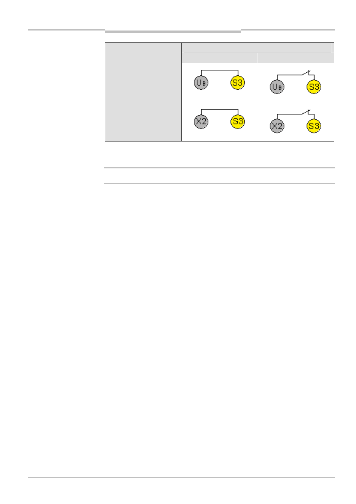
Special applications and
Tab.36:
EDM by means
Operating instructions Chapter 4
Flexi Classic
functions
of S3
Notes
WARNING
S3Connecting
Without EDM With EDM
Without retriggering
With retriggering
• S1 and S3 must always be connected.
• S2 must be connected depending on the program.
All later changes at the connection of S1, S2 and S3 cause a lock-out (ERR).
• During the configuration phase (when the voltage is activated) of the manual reset with
the reset button, the corresponding S-input must be open or be connected to a highresistance output, for example of a PLC (high or low potential causes an incorrect
configuration).
• In order to monitor external contactors that may be connected to the safe outputs Q1 to
Q4, the N/C contacts of the respective contactors or output extensions have to be connected in series with the corresponding control inputs.
8011509/YPP0/2015-10-26 © SICK AG • Industrial Safety Systems • Germany • All rights reserved 77
Subject to change without notice
Page 78
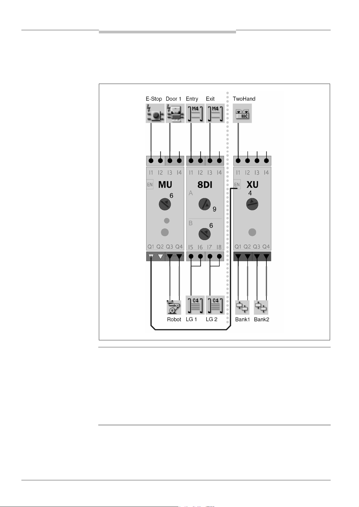
Special applications and
Fig.33:
Cascading of safety
Chapter 4 Operating instructions
functions
Flexi Classic
4.12 Grouping of subsystems
circuits
Note
In case of single-channel wiring of a safety capable output (Q1-Q4) to a signal input (EN), it
is possible to achieve category 4 in accordance with EN ISO 13 849-1 or SILCL3 in accord-
ance with EN 62 061.
78 © SICK AG • Industrial Safety Systems • Germany • All rights reserved 8011509/YPP0/2015-10-26
WARNING
Exclude cross-circuits by means of appropriate cabling!
• If several modules are used (> 1), cross-circuits on test pulse outputs (X1-Xn) can not
always be detected.
• If two modules are used (UE410-MU or UE410-GU and a UE410- XU), cross-circuits on
safety outputs (Q1-Q4) can not always be detected.
= If several modules are used, the possibility of cross-circuits has to be excluded by
means of appropriate cabling measures (protected installation, plastic-sheathed cable
etc.).
Subject to change without notice
Page 79
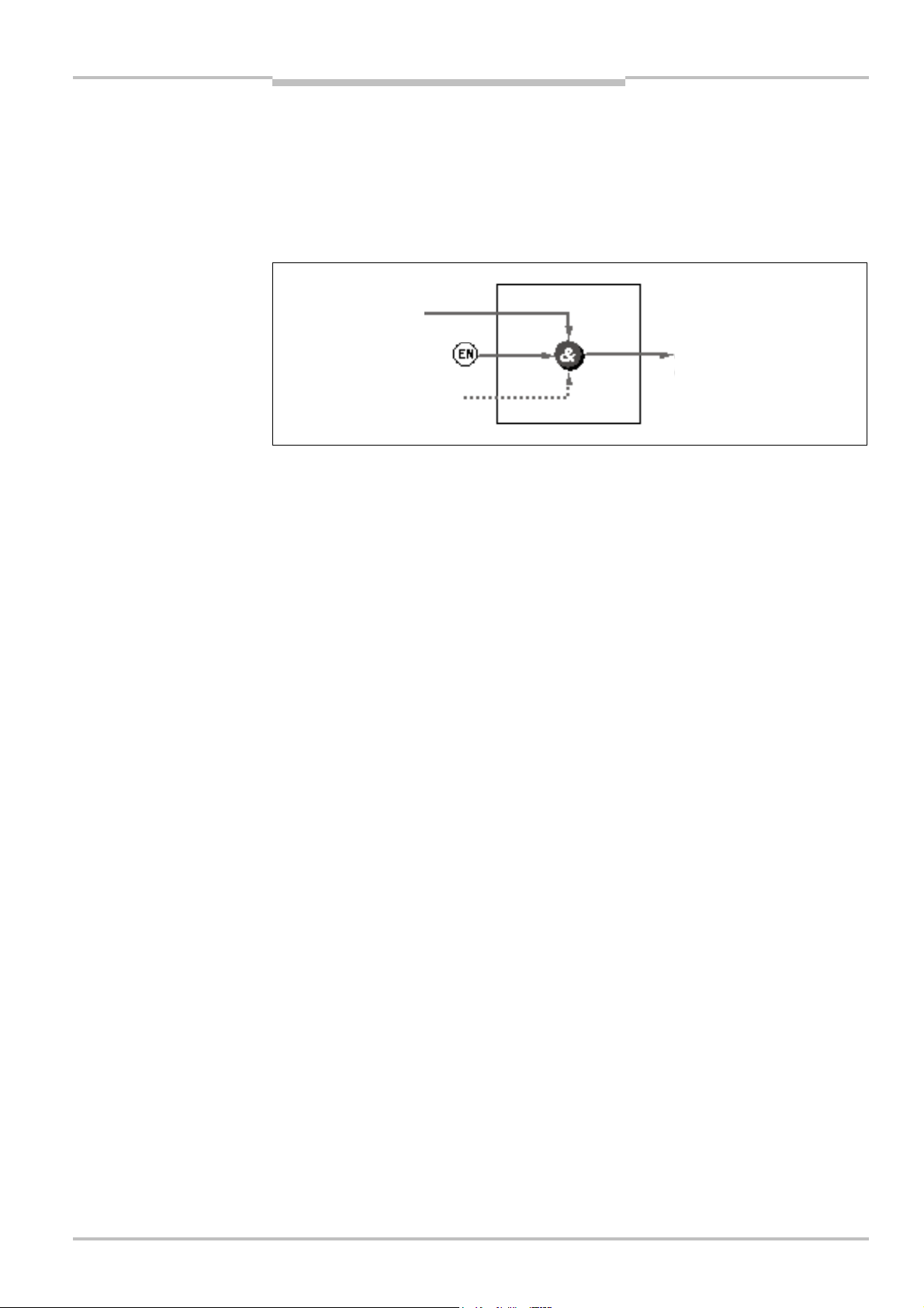
Special applications and
Fig.34:
ENABLE input
ENABLE function
(switch on and switch off
Operating instructions Chapter 4
Flexi Classic
Note
Note
functions
4.13 ENABLE input
For all UE410-MU- and UE410-XU-devices with a type label entry from E1: In case of singlechannel wiring of a safety capable output (Q1-Q4) to a signal input (EN), it is possible to
achieve category 4 in accordance with EN ISO 13 849-1 or SIL3 in accordance with
IEC 61 508.
The ENABLE input is not available on the UE410-GU.
Q
Start
signal for the start function)
Q
EN
(output of the ENABLE function)
Start-up interlock
The ENABLE input makes it possible to cascade safety circuits or to form sub-systems. The
ENABLE input has a higher priority than all other input signals (sensors, muting, bypass,
OR function).
Unused ENABLE inputs must be connected to the supply voltage +UB.
When the ENABLE input goes low (0 V DC), the OSSDs (Q1-Q4) always go low and at the
same time no signal such as a reset or muting is detected until ENABLE is high again.
Switching OFF and switching ON ENABLE does not require a renewed reset on the related
modules, the OSSDs (Q1-Q4) go high.
If a time delay has been set on Q3/Q4, the delay starts after the ENABLE input goes low.
8011509/YPP0/2015-10-26 © SICK AG • Industrial Safety Systems • Germany • All rights reserved 79
Subject to change without notice
Page 80
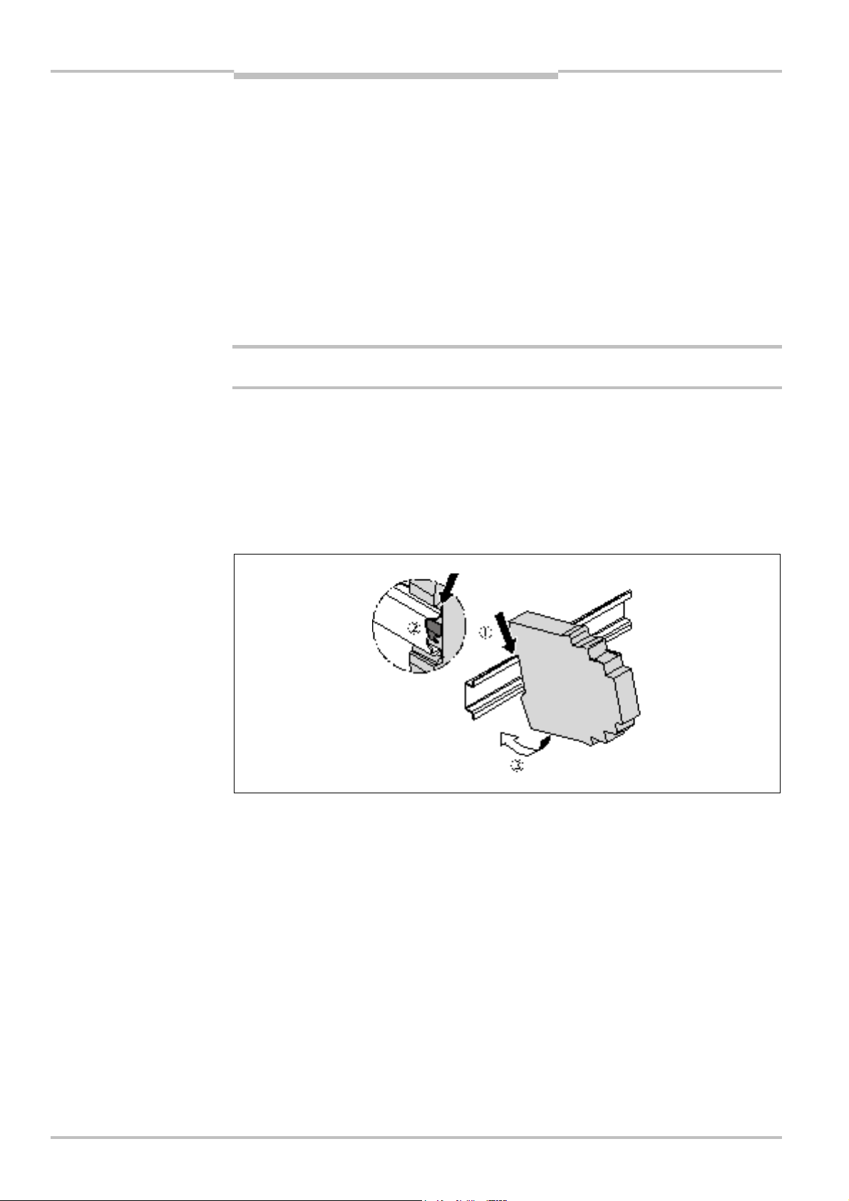
Chapter 5 Operating instructions
Fig.35:
Hanging the module
Mounting/dismantling
Flexi Classic
5 Mounting/dismantling
This chapter describes the mounting of the modules and the anti-manipulation cover for
the Flexi Classic modular safety controller.
The following steps are necessary after mounting and installation:
• completing the electrical connections (chapter 6)
• configuration (chapter 9)
• checking the installation (section 8.2)
5.1 Steps for mounting the modules
WARNING
into the DIN mounting rail
The Flexi Classic system is only for use in a control cabinet rated to at least IP 54.
• In a Flexi Classic system the main module UE410-MU is positioned at the extreme left
and one of the optional gateways, e.g. UE410-PRO, at the extreme right.
• The connection between the modules is effected by means of the plug connection
integrated in the housing.
• Mounting according to EN 50 274
• The modules are located in a 22.5 mm wide housing for 35 mm DIN mounting rails as
per EN 60 715.
80 © SICK AG • Industrial Safety Systems • Germany • All rights reserved 8011509/YPP0/2015-10-26
= Hang the device onto the DIN mounting rail (0).
= Ensure that the earthing spring contact is positioned correctly (1). The earthing spring
contact of the module must contact the DIN mounting rail making good electrical
contact.
= Latch the module onto the DIN mounting rail by pressing it lightly in the direction of the
arrow (2).
Subject to change without notice
Page 81

Operating instructions Chapter 5
Fig.36:
Installing the end
Fig.37:
Removing the plug
-
in
Fig.38:
Disconnecting the
Flexi Classic
clips
Mounting/dismantling
= If there are several modules, slide the modules together individually in the direction of
the arrow until the side plug connection latches in.
= Install end clips on the right and left.
terminals
plug connection
5.2 Steps for dismantling the modules
= Remove the plug-in terminals with wiring and the end clips.
8011509/YPP0/2015-10-26 © SICK AG • Industrial Safety Systems • Germany • All rights reserved 81
Subject to change without notice
Page 82

Chapter 5 Operating instructions
Fig.39:
Removing the
Fig.40:
Anti-manipulation
Mounting/dismantling
Flexi Classic
= If there are several modules, slide the modules away from each other individually in the
direction of the arrow until the side plug connection is separated.
module from the DIN
mounting rail
= Press the module downwards (0) and remove it from the DIN mounting rail in the
direction of the arrow while keeping it pressed down (1).
cover
5.3 Removing the anti-manipulation cover
To prevent tampering on the Flexi Classic, SICK provides an optional anti-manipulation
cover (see section 12.2.6 “Anti-manipulation cover” on page 117).
= Insert a screwdriver in the opening (0).
= The cover fastening is released by upward movements. The cover can be removed (1).
= The cover is closed by engaging it.
82 © SICK AG • Industrial Safety Systems • Germany • All rights reserved 8011509/YPP0/2015-10-26
Subject to change without notice
Page 83

Operating instructions Chapter 6
Flexi Classic
Electrical installation
6 Electrical installation
WARNING
Notes
Switch the entire machine/system off line!
The machine/system could inadvertently start up while you are connecting the devices.
• The Flexi Classic modular safety controller fulfils the EMC requirements in accordance
with the basic specification EN 61 000-6-2 for industrial use and EN 61 131-2 for control systems.
• The control cabinet or mounting housing of the Flexi Classic must at least comply with
enclosure rating IP 54.
• The modules of the Flexi Classic family conform to Class A, Group 1, in accordance with
EN 55 011. Group 1 encompasses all ISM devices in which intentionally generated
and/or used conductor-bound RF energy that is required for the inner function of the
device itself occurs.
• Mounting according to EN 50 274
• In order to ensure EMC safety, the DIN mounting rail must be connected to FE.
• You must connect the Flexi Classic to the same voltage supply as the connected protec-
tive devices.
• To meet the requirements of the relevant product standards (e.g. EN 61 496-1), the
external voltage supply for the devices (SELV) must, among other aspects, be able to
bridge a power failure lasting 20 ms. Suitable power supplies are available as accessories from SICK.
• When several power supplies are used, all mass connections (GND) must be connected
to each other.
• All UE410-GU modules that are on a common global emergency stop cut-off path must
be connected to the same GND connection.
• The power supply as well as all signals connected have to fulfil the regulations for extra-
low voltages with safe separation (SELV, PELV) in accordance with EN 60664 and
EN 50178 (equipment of electrical power installation with electronic devices) or NEC
Class 2 according to UL 1310.
• For installation in environments with overvoltage category III, external protection
elements must be used. The required level of protection as per EN 62 305-1 can be
achieved using an external snubber circuit. The protection elements (SPD – surge
protective devices) must comply with the requirements as per EN 61 643-11.
• The cables of a connected reset button must be laid in separate plastic-sheathed
cables.
• All connected sensors and downstream controllers and wiring/installation must corres-
pond to the required category according to EN ISO 13 849-1 and to the SILCL according
to EN 62 061 (e.g. protected installation, single plastic-sheathed cable with shielding
etc.).
• In order to protect the safety outputs and to increase the life of the module, the external
load must be equipped with e.g. varistors and RC circuits. Please also note that the
selection of the arc suppression can increase the total response time of the safety
function.
8011509/YPP0/2015-10-26 © SICK AG • Industrial Safety Systems • Germany • All rights reserved 83
Subject to change without notice
Page 84

Chapter 6 Operating instructions
WARNING
Electrical installation
Flexi Classic
• The wiring of single-channel safety outputs as well as the external device monitoring
(EDM) and ENABLE (EN) must be performed inside the control cabinet.
• External faults (e.g. cross-circuits) between two modules within a Flexi Classic system
are to be avoided through use of appropriate countermeasures (separating effected
wires, single plastic-sheathed cable etc.). For more informationen on this topic see
section 4.12 “Grouping of subsystems” on page 78.
Special features to note during wiring:
A UE410-8DI has two test pulse generators. This means that short-circuits between odd
(X1) and evenly (X2) numbered outputs will be detected. Short-circuits between two odd
(i.e. X1, X3, X5, X7) or two evenly (i.e. X2, X4, X6, X8) numbered outputs will not be detected (see also section 4.12 “Grouping of subsystems” on page 78).
= Mount the reset device so that it cannot be actuated by a person located in the ha-
zardous area. When operating the reset device, the operator must have full visual
command of the hazardous area.
84 © SICK AG • Industrial Safety Systems • Germany • All rights reserved 8011509/YPP0/2015-10-26
Subject to change without notice
Page 85

Application examples and
Fig.41:
Connection of t
hree
Fig.42:
Connection of an
Operating instructions Chapter 7
Flexi Classic
connection diagrams
7 Application examples and connection diagrams
L21 to the UE410-MU/XU
Note
By taking into account all the necessary boundary conditions and their evaluation in a
Failure Mode and Effects Analysis (FMEA), applications up to a maximum of SIL3
(IEC 61 508) can be achieved.
7.1 L21 on the UE410-MU/XU
Program 3.2 with restart interlock and EDM
emergency stop to the
UE410-MU/XU
7.2 Emergency stop on the UE410-MU/XU
Program 1 with restart interlock and EDM
8011509/YPP0/2015-10-26 © SICK AG • Industrial Safety Systems • Germany • All rights reserved 85
Subject to change without notice
Page 86

Application examples and
Fig.43:
Connection of an
Fig.44:
Connection of a two
-
Chapter 7 Operating instructions
RE300 to the UE410-MU/XU
connection diagrams
Flexi Classic
7.3 RE300 on the UE410-MU/XU
Program 2 with restart interlock and EDM
hand switch IIIC to the
UE410-MU/XU
7.4 Two-hand IIIC on the UE410-MU/XU
Program 4 without restart interlock and with EDM
86 © SICK AG • Industrial Safety Systems • Germany • All rights reserved 8011509/YPP0/2015-10-26
Subject to change without notice
Page 87
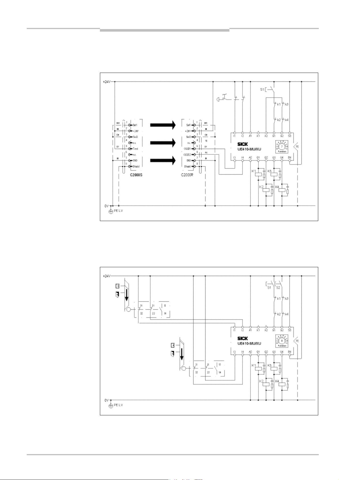
Application examples and
Fig.45:
Connection of a
Fig.46:
Connection of two
Operating instructions Chapter 7
Flexi Classic
C2000 and emergency stop
to the UE410-MU/XU
connection diagrams
7.5 C2000 and emergency stop on the UE410-MU/XU,
two hazardous areas
Program 7 with restart interlock and EDM
i11 to the UE410-MU/XU, two
hazardous areas
7.6 i11 on the UE410-MU/XU, two independent hazardous
areas
Program 8 with restart interlock and EDM
8011509/YPP0/2015-10-26 © SICK AG • Industrial Safety Systems • Germany • All rights reserved 87
Subject to change without notice
Page 88
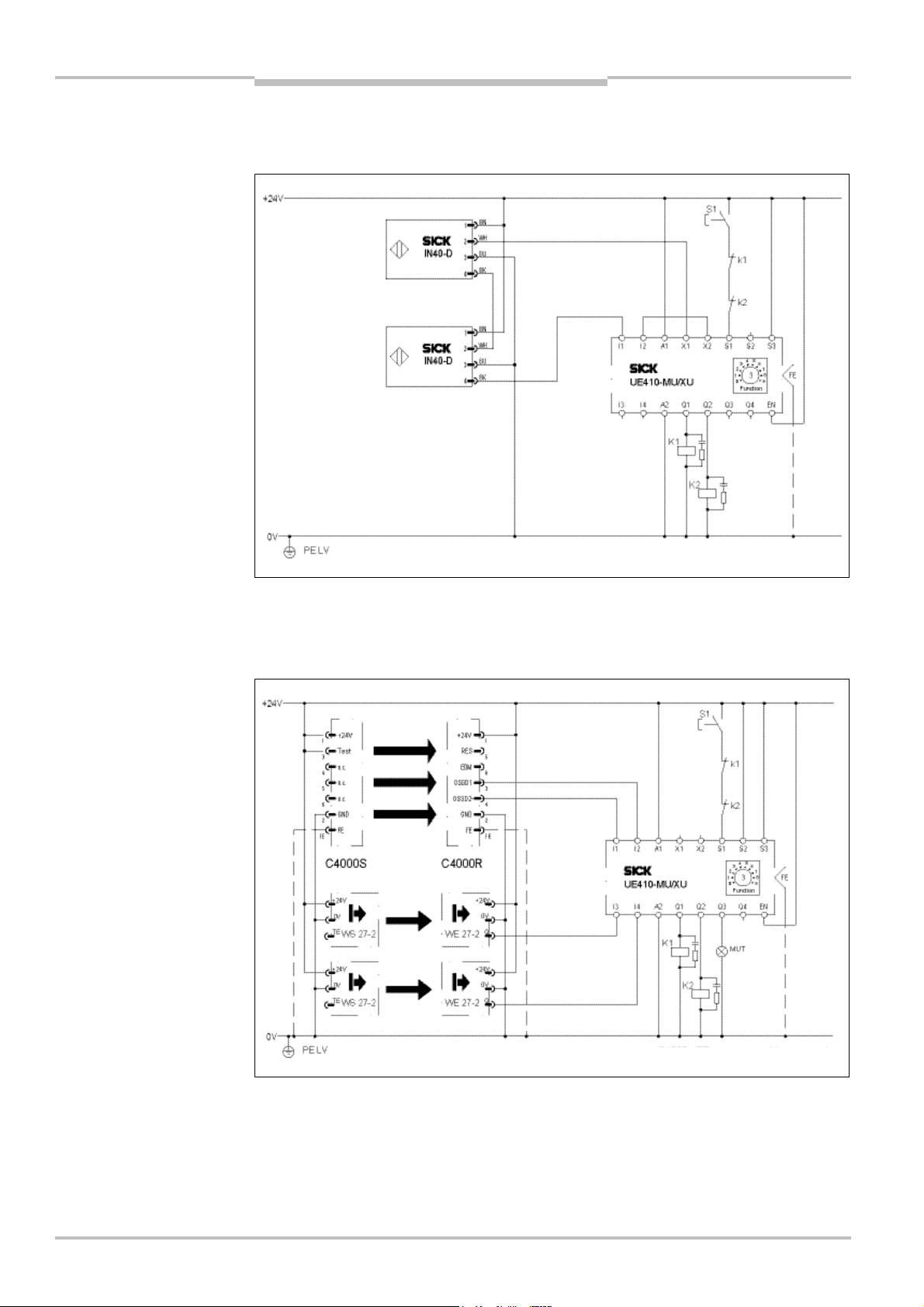
Application examples and
Fig.47:
Connection of two
Fig.48:Connection of a
C4000
-
FE must be connected
Chapter 7 Operating instructions
IN4000 to the UE410-MU/XU
connection diagrams
Flexi Classic
7.7 IN4000 on the UE410-MU/XU
Program 3.2 with restart interlock and EDM
C4000 to the UE410-MU/XU,
2-sensor muting
7.8 C4000 on the UE410-MU/XU, 2-sensor muting
Program 3.1 with restart interlock and EDM
88 © SICK AG • Industrial Safety Systems • Germany • All rights reserved 8011509/YPP0/2015-10-26
Subject to change without notice
Page 89

Application examples and
Fig.49:
Global emergency
Operating instructions Chapter 7
Flexi Classic
stop with two UE410-GU
connection diagrams
7.9 Global emergency stop with two UE410-GU
Program 1 (global emergency stop only)
8011509/YPP0/2015-10-26 © SICK AG • Industrial Safety Systems • Germany • All rights reserved 89
Subject to change without notice
Page 90

Chapter 8 Operating instructions
Commissioning
Flexi Classic
8 Commissioning
Do not commission without a check by qualified safety personnel!
WARNING
WARNING
Note
Note
Before the initial commissioning of the system in which you are using a Flexi Classic modular safety controller, it must be checked and released documented by qualified safety
personnel.
Check the hazardous area!
You must ensure that no one is located in the hazardous area before commissioning.
= Check the hazardous area and secure it against being entered by people (e.g. set up
warning signs, attach blocking ropes or similar). Observe the relevant laws and local
regulations.
8.1 Validation of the application
You may only commission the system if validation was successful. Validation may only be
performed by professionals trained accordingly.
The general acceptance comprises the following test points:
= Check whether the connection of the components to the connections corresponds to
the required Performance Level in accordance with EN ISO 13 849-1 or to the SIL in
accordance with IEC 61 508 or the SILCL in accordance with EN 62 061.
= Check the devices connected to the safety controller in accordance with the test notes
from the accompanying operating instructions.
You will find the “Tests before the first commissioning” chapter for this in the operating
instructions of the ESPE from SICK AG.
= Clearly mark all connection cables and plugs at the safety controller.
= Perform a complete verification of the safety functions of the system in each operating
mode and an error simulation. Observe the response times of the individual applications in particular.
Completely document the configuration of the system, the individual devices and the result
of the safety check.
The software for the configuration documentation is available
• on the Internet under http://www.sick.com/senscontrol
• on the Flexi Classic Mini CD (part no. 2040332)
90 © SICK AG • Industrial Safety Systems • Germany • All rights reserved 8011509/YPP0/2015-10-26
Subject to change without notice
Page 91

Operating instructions Chapter 8
Flexi Classic
Commissioning
8.2 Test notes
8.2.1 Tests before the first commissioning
The purpose of the tests before the first commissioning is to confirm the safety requirements specified in the national/international rules and regulations, especially in the
Machine and Work Equipment Directive.
= Check the effectiveness of the protective device mounted to the machine, using all
selectable operating modes and functions.
= Ensure that the operating personnel of the machine fitted with the safety controller are
instructed by the qualified safety personnel of the machine owner before beginning
work. Instructing the operating personnel is the responsibility of the machine owner.
8.2.2 Regular testing
The Flexi Classic system must be tested regularly.
In order to reach SILCL3 in accordance with EN 62 061 (see chapter 11 “Technical
WARNING
specifications” on page 96), the following test must be made at least every 365 days:
• The Flexi Classic system must be powered down.
• The Flexi Classic system must be powered up.
• All safety functions of the connected safety sensors must be verified.
8.2.3 Regular inspection of the protective device by qualified safety personnel
= Check the system following the inspection intervals specified in the national rules and
regulations. This procedure ensures that any changes on the machine or manipulations
of the protective device after the first commissioning are detected.
= Each safety application must be checked at an interval specified by you. The effective-
ness of the protective devices must be tested by qualified personnel.
= If any modifications have been made to the machine or the protective device, or if the
safety controller has been changed or repaired, the system must be checked again as
specified in the checklist in the annex.
8011509/YPP0/2015-10-26 © SICK AG • Industrial Safety Systems • Germany • All rights reserved 91
Subject to change without notice
Page 92

Chapter 9 Operating instructions
Configuration
Flexi Classic
9 Configuration
Check the configuration for the protective device after every change!
WARNING
If you change the configuration, you must check the effectiveness of the protective device.
Please observe the test notes in the operating instructions of the connected protective
device.
To configure the Flexi Classic you will need:
• a screwdriver
9.1 Accepting the system configuration
= Switch off the voltage supply (terminals A1, A2) at all the main modules.
= Use a screwdriver to set the desired switch positions (programs and functions) at the
rotary switches of all the modules of the system.
= Set the control functions at all the modules of the system by external connecting of the
terminals S1, S2 and S3.
= Switch on the voltage supply of all the modules while keeping the ENTER button of the
main module UE410-MU or UE410-GU pressed.
WARNING
Note
WARNING
Do not actuate any of the RESET buttons connected when in this state!
= When the ERR indicator begins to flash, release the ENTER button within 3 seconds.
The selected operating mode is stored in non-volatile memory and is active.
If the ENTER button is pressed for more than 3 seconds, the entire system switches to the
error state. The ERR indicator flashes.
Please refer to the description in section 10.4 “Error indications of the ERR error LED” on
page 94.
All later changes at the connection of S1, S2 and S3 will cause a lock-out (ERR).
92 © SICK AG • Industrial Safety Systems • Germany • All rights reserved 8011509/YPP0/2015-10-26
Subject to change without notice
Page 93

Operating instructions Chapter 10
Flexi Classic
Diagnostics
10 Diagnostics
10.1 In the event of faults or errors
Cease operation if the cause of the malfunction has not been clearly identified!
WARNING
Stop the machine if you cannot clearly identify or allocate the error and if you cannot safely
rectify the malfunction.
Complete function test after rectification of fault!
Carry out a full functional test after a malfunction has been remedied.
The ERROR operational status
With certain malfunctions or a faulty configuration, the Flexi Classic enters the safe status.
The ERR LEDs of the safety controller modules show the corresponding errors. To place
the device back in operation:
= Rectify the cause of the malfunction in accordance with the indication of the ERR LED.
= Switch the voltage supply of the Flexi Classic off and back on again.
10.2 Replacement of a module
If in an existing Flexi Classic system a module is replaced, the following has to be
observed:
UE410-MU and UE410-GU
Each time a device is replaced, it is necessary to accept the system configuration again
(see section 9.1 “Accepting the system configuration” on page 92).
UE410-XU
If in an existing Flexi Classic system a device is replaced by another device with a differing
revision code (e.g. C-XX to E-XX), then it is necessary to accept the system configuration
again (see section 9.1 “Accepting the system configuration” on page 92). This is not
necessary if the revision code remains the same.
UE410-8DI
If in an existing Flexi Classic system a device is replaced by another device with a differing
revision code (e.g. C-XX to E-XX), then the system configuration must be accepted again
(see section 9.1 “Accepting the system configuration” on page 92). This is not necessary if
the revision code remains the same.
Additionally from revision code D-XX or higher you must pay attention to the wiring: If the
devices were wired as described in these operating instructions (see section 3.8.5
“Connection of sensors to the UE410-8DI” on page 54), no change is necessary. If the
devices were wired e.g. via external distributor modules (X1 and X2 led back to I1 to I8),
then a module exchange from revision code ≤ C-XX to ≥ D-XX requires that connection I5 is
exchanged with I6 and I7 is exchanged with I8.
8011509/YPP0/2015-10-26 © SICK AG • Industrial Safety Systems • Germany • All rights reserved 93
Subject to change without notice
Page 94

Chapter 10 Operating instructions
Tab.37:
Error indications of
Diagnostics
Flexi Classic
10.3 SICK support
If you cannot rectify an error with the help of the information provided in this chapter,
please contact your local SICK representative.
Note
If you send in a device for repair, you will receive it back in the delivery state. Therefore
write down the configuration(s) of your devices.
10.4 Error indications of the ERR error LED
This section explains what the LED error indications mean and how you can respond.
the ERR LED
Note
LED indicators Possible cause Rectification of the error
Ν
2 × ∏ Error at the module configuration = Repeat the configuration.
3 × ∏ Rotary switch manipulated
4 × ∏
5 × ∏ Supply voltage defective = Check the voltage supply.
6 × ∏ Self-diagnostics, internal error, etc.
S3 and ENABLE must always be wired on the UE410-MU/XU. Otherwise the outputs Q1-Q4
cannot be enabled.
Sequential error on modules that
did not detect the error initially
Change to the configuration in the
electrically unpowered state
• on the rotary switch or
• to S1-S3 (UE410-MU/XU only)
or
Slot list comparison found difference or differing module revisions
= Eliminate the error at the
respective module.
= Turn the rotary switch back to
the original position.
= Carry out a power-up or repeat
teaching-in.
= Reset configuration to original
state or
= Re-connect module to original
position or
= Carry out a power-up and accept
the configuration again.
= Cycle power. Check wiring and
rotary switch setting.
94 © SICK AG • Industrial Safety Systems • Germany • All rights reserved 8011509/YPP0/2015-10-26
Subject to change without notice
Page 95

Operating instructions Chapter 10
Tab.38:
Anti-manipulation
Flexi Classic
Diagnostics
10.5 Anti-manipulation measures
measures
Reaction of the system Cause Rectification of the error
• Immediate de-activa-
tion of all outputs
• System changes to
“System error” status.
• Red ERR LED of the
respective module
Changeover of a
rotary switch
= Return the switch back to the old
position (setting aid if voltage
remains activated: flashing PWR
LED changes to steady green).
= Restart the system by switching
the voltage off and on again.
flashes.
• Green PWR LED
flashes.
• All other ERR LEDs to
steady red
• Message via diagnos-
tics module
• De-activation of the
outputs of the system/
subsystem during the
next cycle
UE410-MU/XU only:
Change in the control
circuit configuration
(inputs S1, S2, S3)
= Reset the old configuration at
S1, S2, S3.
= Restart the system by switching
the voltage off and on again.
• Red ERR LED of the
respective module
flashes.
• Message via diagnos-
tics module
The last configurations
are saved internally in
non-volatile memory and
can be read by the
manufacturer if required.
• Outputs of the system
cannot be activated.
• Red ERR LED of the
master module
(UE410-MU) flashes.
• All other ERR LEDs to
steady red
• Outputs of the
system/subsystem
cannot be activated.
• Red ERR LED of the
master module
(UE410-MU) flashes.
• All other ERR LEDs to
steady red
Intentional use of an
incorrect
configuration
Changeover of a
rotary switch
UE410-MU/XU only:
Change in the control
circuit configuration
(inputs S1, S2, S3)
You can read out the last (correct)
configuration using one of the Flexi
Classic Gateways.
= Check the configuration visually
at regular intervals.
= Return the switch back to the old
position (setting aid if voltage
remains activated: flashing PWR
LED changes to steady green).
= Restart the system by switching
the voltage off and on again.
= Reset the old configuration at
S1, S2, S3.
= Restart the system by switching
the voltage off and on again.
8011509/YPP0/2015-10-26 © SICK AG • Industrial Safety Systems • Germany • All rights reserved 95
Subject to change without notice
Page 96
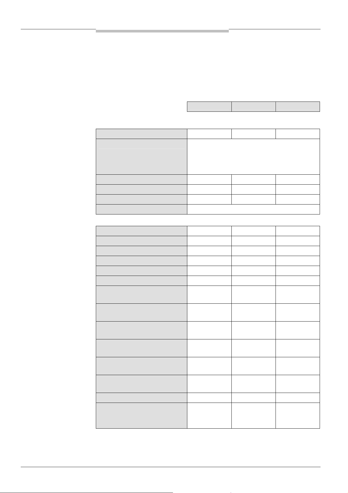
Chapter 11 Operating instructions
Tab.39:
Data sheet
Technical specifications
Flexi Classic
11 Technical specifications
11.1 Data sheet
11.1.1 UE410-MU/UE410-XU modules
UE410-MU/UE410-XU
Minimum Typical Maximum
Supply circuit (A1, A2)
Supply voltage U
B
Type of supply voltage
19.2 V DC 24 V DC 30 V DC
PELV or SELV
The current of the power supply unit for the main
module has to be limited to a maximum of 6 A —
either by the power supply unit itself or by a fuse.
Residual ripple U
ss
– – 3 V
Power consumption – – 3 W
Maximum switch-on time – – 60 s
Short-circuit protection 4 A gG with tripping characteristic B or C
Input circuit (I1-I4, EN, S1-S3)
Number of inputs – – 8
Input voltage (high) 13 V DC – 30 V DC
Input voltage (low) –5 V DC – 5 V DC
Input current (high) 2.4 mA 3 mA 3.8 mA
Input current (low) –2.5 mA – 2.1 mA
Input capacitance 9 nF 10 nF 11 nF
Minimum switch-off time
10)
(I1/I2)
7 ms – –
program 3.1, 7, 8
Minimum switch-off time
10)
(I1/I2)
20 ms – –
program 1, 2, 4, 5, 6, 9
Minimum switch-off time
10)
(I1/I2)
20 ms – –
pressure sensitive mat
Minimum switch-off time
10)
(I3/I4)
7 ms – –
program 1, 2, 7, 8, 9
Minimum switch-off time
10)
(I3/I4)
20 ms – –
program 4, 5, 6
Minimum switch-off time
10)
70 ms/20 ms – –
(X1-I1/X2-I2) program 3.2
Minimum switch-off time (EN) 7 ms – –
Maximum break time of the input
– – 1 ms
signal without switching of the
outputs (Q1-Q4)
10)
Time without sensor, the data for the sensors connected apply in addition.
96 © SICK AG • Industrial Safety Systems • Germany • All rights reserved 8011509/YPP0/2015-10-26
Subject to change without notice
Page 97
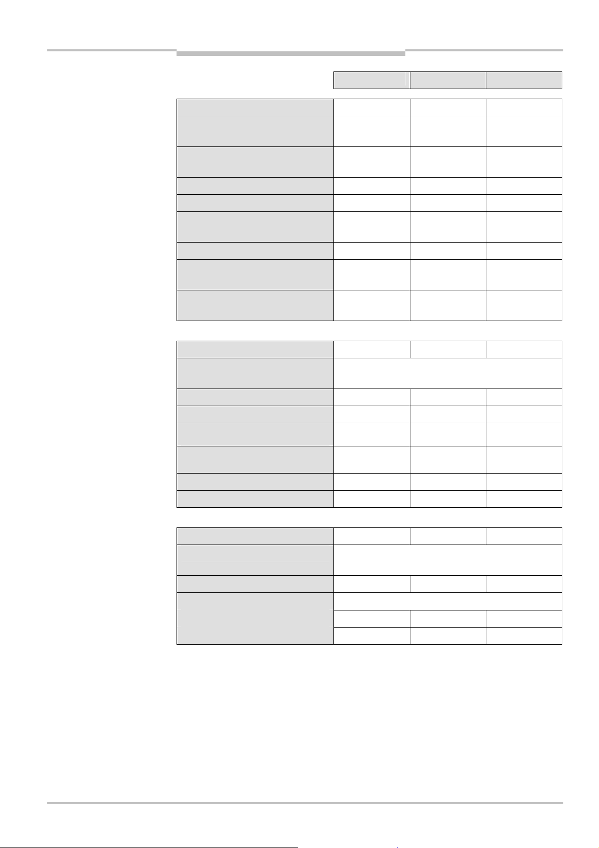
Operating instructions Chapter 11
Flexi Classic
Technical specifications
Minimum Typical Maximum
Power-up delay 70 ms – –
Synchronous time monitoring
– 1500 ms –
program 1, 2
Synchronous time monitoring
– 500 ms –
program 4 and 5
Muting ON program 3
11)
– – 61 ms
Muting OFF program 3 – 61 ms 165 ms
Muting gap suppression
program 3
13)
95 ms – 100 ms
Reset time – – 124 ms
Teach-in time of ENTER button
– – 3 s
UE410-MU (during power-up)
Duration of actuation of the reset
50 ms – 5 s
button (only S1, S2)
Control outputs (X1, X2)
Number of outputs – – 2
Type of output
PNP semiconductors, short-circuit protected, crosscircuit detecting
14)
Output voltage 16 V DC – 30 V DC
Output current
Test period (X1, X2) program 1, 2,
15)
– – 120 mA
–
– 40 ms
4, 5, 6, 9
Test period (X1, X2) program 3.2 –
–
X1 = 384 ms
X2 = 40 ms
Load capacity – – 1,000 nF
12)
Cable resistance – – 100 Ω
Output circuit (Q1, Q2, Q3, Q4)
Number of outputs – 4 –
Type of output
PNP semiconductors, short-circuit protected, crosscircuit detecting
14)
Switching voltage 18.4 V DC – 30 V DC
Switching current
IQn, TA ≤ 45 °C – – 2,0 A
IQn, TA ≤ 55 °C – – 1,6 A
11)
Time between muting condition valid (I3/I4 high) and muting possible.
12)
Max. switch-off time at muting error.
13)
One muting input (I3 or I4) may be LOW for the specifi ed time.
14)
Cross circuit detecting only within a module.
15)
The total output current for a Flexi Classic system is limited. The current for supplying all sensors that are
connected to the UE410-MU/XU (X1/X2) and UE410-8DI (X1-X8) must be I < 600 mA and the current on a
Flexi Classic gateway must be I < 100 mA . If this total current is insufficient, please contact the SICK hotline.
8011509/YPP0/2015-10-26 © SICK AG • Industrial Safety Systems • Germany • All rights reserved 97
Subject to change without notice
Page 98

Chapter 11 Operating instructions
Σ
IQn [A]
TA [°C]
T
Technical specifications
Flexi Classic
Minimum Typical Maximum
Total current I
sum
ΣIQn, TA ≤ 45 °C – – 4 A
ΣIQn, TA ≤ 55 °C – – 3.2 A
Load diagram for the Q1 to Q4 outputs of the
UE410-MU/UE410-XU modules
Total current per temperature
A max
Test pulse width 500 μs 640 μs 700 μs
Test pulse frequency 12.5 Hz – 32 Hz
Inductive switch-off energy
– – 370 mJ
E = 0.5 × L × I²
Load capacity – – 500 nF
Cable length (single, ⊕ 1.5 mm2) – – 100 m
Response time (I1/I2)
16)
program
– – 13 ms
3.1, 7, 8
Response time (I1/I2)
16)
program
– – 29 ms
1, 2, 4, 5, 6, 9
Response time (I1/I2)
16)
program
– – 38 ms
1 pressure sensitive mat
Response time of all programs
– – 56 ms
with tested ESPE Cat. 4 (e.g. L41)
Response time (I3/I4)
16)
– – 13 ms
program 1, 2, 7, 8, 9
Response time (I3/I4)
16)
– – 29 ms
program 4, 5
Response time (I1-X1, I2-X2)
16)
– – 79 ms/29 ms
program 3.2
Response time
17)
on connection of
56 ms
Flexi Loop
16)
Time without sensor, the data for the sensors connected apply in addition.
17)
Response time not including Flexi Loop and not including sensor. Also take into account the response times of
Flexi Loop and the sensors connected.
98 © SICK AG • Industrial Safety Systems • Germany • All rights reserved 8011509/YPP0/2015-10-26
Subject to change without notice
Page 99
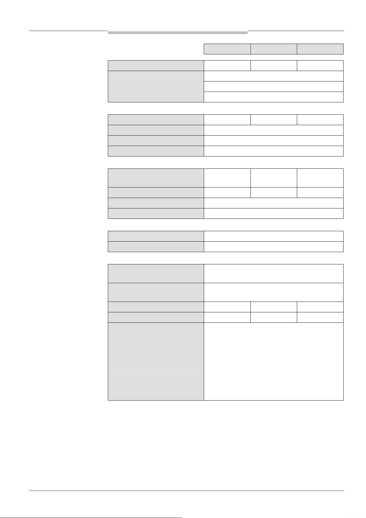
Operating instructions Chapter 11
Flexi Classic
Technical specifications
Minimum Typical Maximum
Response time (EN)
Time delay (adjustable)
18)
– – 13 ms
0 / 0.5 / 1 /1.5 / 2 / 2.5 / 3 / 3.5 / 4 / 5 s
0 / 5 / 10 / 15 / 20 / 25 / 30 / 35 / 40 / 50 s
0 / 0.5 / 1 / 1.5 / 2 / 2.5 / 3 / 3.5 / 4 / 5 min
General system data
Weight (without packaging) – 0.18 kg –
Electrical safety Class III
Interference resistance EN 61 000-6-2
Radiated emission EN 61 000-6-4
Operating data
Ambient operating temperature
–25 °C – 55 °C
(UL/CSA: ambient temperature)
Storage temperature –25 °C – 70 °C
Air humidity 10 % to 95 %, non-condensing
Climatic conditions EN 61 131-2
Mechanical strength
Vibration EN 61 131-2
Vibration resistance 5-500 Hz/5 grms (EN 60 068-2-64)
Terminal and connection data
Single-wire or fine-wire
1 × 0.14 mm² to 2.5 mm² or
2 × 0.14 mm² to 0.75 mm²
Fine-wire with terminal crimps to
EN 46 228
1 × 0.25 mm² to 2.5 mm² or
2 × 0.25 mm² to 0.5 mm²
Insulation stripping length – – 8 mm
Maximum tightening torque – – 0.6 Nm
For UL 508 and CSA applications
UE410-xx3…, UE410-xxx3…
– Connection cross-section AWG 30-12
(only use 60/75 °C copper flexible wire)
– Tightening torque
5-7 lb⋅in
UE410-xx4…, UE410-xxx4…
– Connection cross-section AWG 30-12
(only use 60/75 °C copper flexible wire)
18)
Cascading subsystems.
8011509/YPP0/2015-10-26 © SICK AG • Industrial Safety Systems • Germany • All rights reserved 99
Subject to change without notice
Page 100

Chapter 11 Operating instructions
Tab.40:
PFD and PFHd
Technical specifications
Flexi Classic
Minimum Typical Maximum
Safety specific characteristics
All these data are based on an ambient temperature of +40 °C.
19)
19)
SIL3 (IEC 61 508)
SILCL3 (EN 62 061)
Safety Integrity Level
SIL claim limit
Category Category 4 (EN ISO 13 849-1)
Performance Level
19)
PL e (EN ISO 13 849-1)
TM (mission time) 20 years (EN ISO 13 849-1)
PFD 3.9 × 10
PFHd (1/h) 2.5 × 10
-6
-9
SFF 96 %
DC 99 %
values for UE410-MU/
UE410-XU
Single-channel
input, single-
channel output
PFD (⊕) 2.2 × 10
–5
Single-channel
input, dual-
channel output
5.2 × 10
–6
Dual-channel
input, single-
channel output
2.1 × 10
–5
Dual-channel
input, dual-
channel output
3.9 × 10
% of SIL3 2.2 % 0.5 % 2.1 % 0.4 %
PFHd (1/h) 6.0 × 10
–9
2.5 × 10
–9
6.0 × 10
–9
2.5 × 10
% of SIL3 6.0 % 2.5 % 6.0 % 2.5 %
–6
–9
100 © SICK AG • Industrial Safety Systems • Germany • All rights reserved 8011509/YPP0/2015-10-26
19)
For detailed information on the safety design of your machine/system, please contact your local SICK
representative.
Subject to change without notice
 Loading...