

Page 1
B ET R I E BS AN L E I TU NG
Hersteller und Betreiber der Maschine, an der ein
e
UE10-3OS
Erweiterungsgerät für
Basisgeräte
de
SICK AG • Industrial Safety Systems
ErwinSick-Straße 1
D-79183 Waldkirch • www.sick.com
8009656/YSS0/2016-03-17 • REIPA/XX
Printed in Germany (2016-03) • Alle Rechte
vorbehalten • Irrtümer und Änderungen vorbehalten
1 Geltungsbereich
Diese Betriebsanleitung ist gültig für die Erweiterungsgeräte UE103OS für Basisgeräte mit dem folgenden
Typenschild-Eintrag im Feld Operating Instructions:
8009656
Das Herstellungsdatum des Gerätes finden Sie auf
dem Typenschild im Feld Date Code im Format jjwwxxxx
(jj = Jahr, ww = Kalenderwoche, xxxx = Seriennummer).
Diese Betriebsanleitung ist eine Original-Betriebsanleitung.
2 Zur Sicherheit
Dieses Kapitel dient Ihrer Sicherheit und der Sicherheit
der Anlagenbediener.
Bitte lesen Sie dieses Kapitel sorgfältig, bevor S ie
mit dem UE103OS oder der durch das UE103OS
geschützten Maschine arbeiten.
2.1 Befähigte Personen
Das Erweiterungsgerät UE103OS darf nur von befähigten Personen montiert, installiert, in Betrieb genommen und geprüft werden.
Befähigt ist, wer …
über eine geeignete technische Ausbildung verfügt
und
vom Maschinenbetreiber in der Bedienung und den
gültigen Sicherheitsrichtlinien unterwiesen wurde
und
Zugriff auf die Betriebsanleitung des Erweiterungs-
gerätes UE103OS und diese gelesen und zur
Kenntnis genommen hat.
2.2 Verwendungsbereiche des Gerätes
Das Erweiterungsgerät UE103OS ist einsetzbar:
gemäß EN ISO 13 849 bis PL e und Kategorie 4
gemäß EN 62 061 bis SILCL3
gemäß IEC 61 508 bis SIL3
Der tatsächlich erreichte Performance Level bzw. die
erreichte SIL-Anspruchsgrenze hängt von der Außenbeschaltung, der Ausführung der Verdrahtung, der
Wahl der Befehlsgeber und deren Anordnung an der
Maschine ab.
Das Erweiterungsgerät UE10-3OS wurde nach UL 508
getestet.
Das Erweiterungsgerät UE103OS dient zum Gebrauch an
berührungslos wirkenden Schutzeinrichtungen (BWS) mit
überwachtem aktivem Schaltausgang (OSSD):
einkanalig, zweikanalig (gemäß IEC 614 961)
Sicherheitsgeräten mit überwachten Halbleiter-
ausgängen, wie z.B. Flexi Classic und Flexi Soft
Das UE103OS hat keine Wiederanlaufsperre und keine
Schützkontrolle.
2.3 Bestimmungsgemäße Verwendung
Das Erweiterungsgerät UE103OS darf nur im Sinne von Abschnitt 2.2 „Verwendungsbereiche des Gerätes“ verwendet
werden.
Es darf nur von befähigten Personen und nur an der Maschine verwendet werden, an der es gemäß der Betriebsanleitung von einer befähigten Person montiert und erstmals in
Betrieb genommen wurde. Bei jeder anderen Verwendung
sowie bei Veränderungen am Gerät – auch im Rahmen von
Montage und Installation – verfällt jeglicher Gewährleistungsanspruch gegenüber der SICK AG.
2.4 Allgemeine Sicherheitshinweise und
Schutzmaßnahmen
Beachten Sie die Sicherheitshinweise und
Schutzmaßnahmen!
Beachten Sie die nachfolgenden Punkte, um die
bestimmungsgemäße Verwendung des Erweiterungsgerätes UE103OS zu gewährleisten.
Beachten Sie bei Montage, Installation und An-
wendung des Erweiterungsgerätes die in Ihrem
Land gültigen Normen und Richtlinien.
Für Einbau und Verwendung des Erweiterungsge-
rätes sowie für die Inbetriebnahme und wiederkehrende technische Überprüfung gelten die
nationalen/internationalen Rechtsvorschriften,
insbesondere:
– dieMaschinenrichtlinie
– dieArbeitsmittelbenutzungsrichtlinie
– dieEMV-Richtlinie
– dieUnfallverhütungsvorschriften und Sicher-
heitsregeln
Erweiterungsgerät verwendet wird, müssen alle
geltenden Sicherheitsvorschriften/-regeln in
eigener Verantwortung einhalten.
Die Prüfungen sind von befähigten Personen
bzw. von eigens hierzu befugten und beauftragten Personen durchzuführen und in jederzeit von
Dritten nachvollziehbarer Weise zu dokumentieren.
Die Betriebsanleitung ist dem Bediener der Ma-
schine, an der das UE103OS verwendet wird,
zur Verfügung zu stellen.
Der Maschinenbediener ist durch befähigte Per-
sonen einzuweisen und zum Lesen der Betriebsanleitung anzuhalten.
2.5 Umweltgerechtes Verhalten
Die Entsorgung unbrauchbarer oder irreparabler Geräte
muss immer gemäß den jeweils gültigen landesspezifischen
Abfallbeseitigungsvorschriften (z. B.Eur opäischerA bfallschlüssel 16 02 14) erfolgen.
3 Produktbeschreibung
Über die kontaktbehafteten Schaltausgänge des Erweiterungsgerätes können die zugehörigen Aktoren der Maschine
oder Anlage sicher abgeschaltet werden.
DasSchalten derHalbleiterausgängeder vorgeschalteten
Basisgerätesteuert überdie zweiseparatenEingangskreise
die internenRelais. DieFreigabestrompfade dienen alssichere
Ausgänge. DerMeldestrompfadist ein nichtsicherer Ausgang.
DerRückmeldestrompfaddient alsSchützkontrolle fürdie
Überwachungdurch das Basisgerät.
Schließen Sie zur Erreichung von SIL3/PL e die
Schützkontrolle an!
Um SIL3/PL e zu erreichen, muss eine externe Diagnose mit DC R 99 % angewendet werden (d.h. die
Schützkontrolle muss angeschlossen sein).
Beachten Sie hierzu auch Kapitel 11
„Applikationsbeispiele“.
Anzeigeelemente
Anzeige Bedeutung
K1 Grün Kanal 1 geschaltet
K2 Grün Kanal 2 geschaltet
4 Montage
Montage nur mit Schutzart IP 54 oder höher!
Das Erweiterungsgerät darf nur im Schaltschrank
montiert werden. Der Schaltschrank muss mindestens die Schutzart IP 54 erfüllen.
Montage gemäß EN 50 274.
Die Module sind in einem 22,5 mm breiten Aufbau-
gehäuse für 35-mm-Hutschienen gemäß EN 607 15
untergebracht.
5 Elektroinstallation
Hinweis:
Alle angeschlossenen Leistungs-Schaltelemente und die
Leitungen müssen eine Stromtragfähigkeit, maximalem
Kurzschlussstrom (gemäß EN 60947-5-1) von I
besitzen.
Anlage spannungsfrei schalten!
Die Spannungsversorgung muss den Vorschriften für
Kleinspannungen mit sicherer Trennung (SELV, PELV) für
Überspannungskategorie II gemäß EN 60 664 und
EN 50 178 genügen.
Hinweis:
Die Überspannungskategorie III kann erreicht werden,
wenn die Kontaktkreise Y1/Y2 und 41/42 im selben
Stromkreis betrieben werden wie die vorgeschalteten
OSSDs (Schutzkleinspannung). Bei Installation in Umgebungen der Überspannungskategorie III müssen
externe Schutzelemente verwendet werden.
Alle Anschlüsse, Verdrahtung und Verlegung müssen
der geforderten Kategorie gemäß EN ISO 13 849 und
EN 62 061 entsprechen (z.B. geschützte Verlegung,
Einzelmantelleitung mit Schirm etc.).
Eingänge B2 und B4 immer mit dem 0VPotenzial der
Versorgungsspannung der Basisgeräte verbinden.
Um die Kontaktausgänge des UE103OS zu schützen
und die Lebensdauer zu erhöhen, müssen die angeschlossenen Lasten mit z. B.Varis toren undR C-Gliedern
ausgerüstet werden. Hierbei ist zu beachten, dass sich
die Ansprechzeiten je nach Art der Schutzbeschaltung
verlängern.
DieSicherheitsausgängeund dieS chützkontrolle(EDM)
müsseninnerhalbdes Schaltschranksverdrahtetwerden.
Um das Verschweißen der Kontakte der eingebauten
Relais zu verhindern, ist eine Überstromschutzeinrichtung
mit max. 6 A Kurzschlussschutz (Betriebsklasse gG) in die
Strompfade einzubinden (siehe Abb. 2, Freigabestrompfade-Sicherung F2/F3/F4).
max
= 1000 A
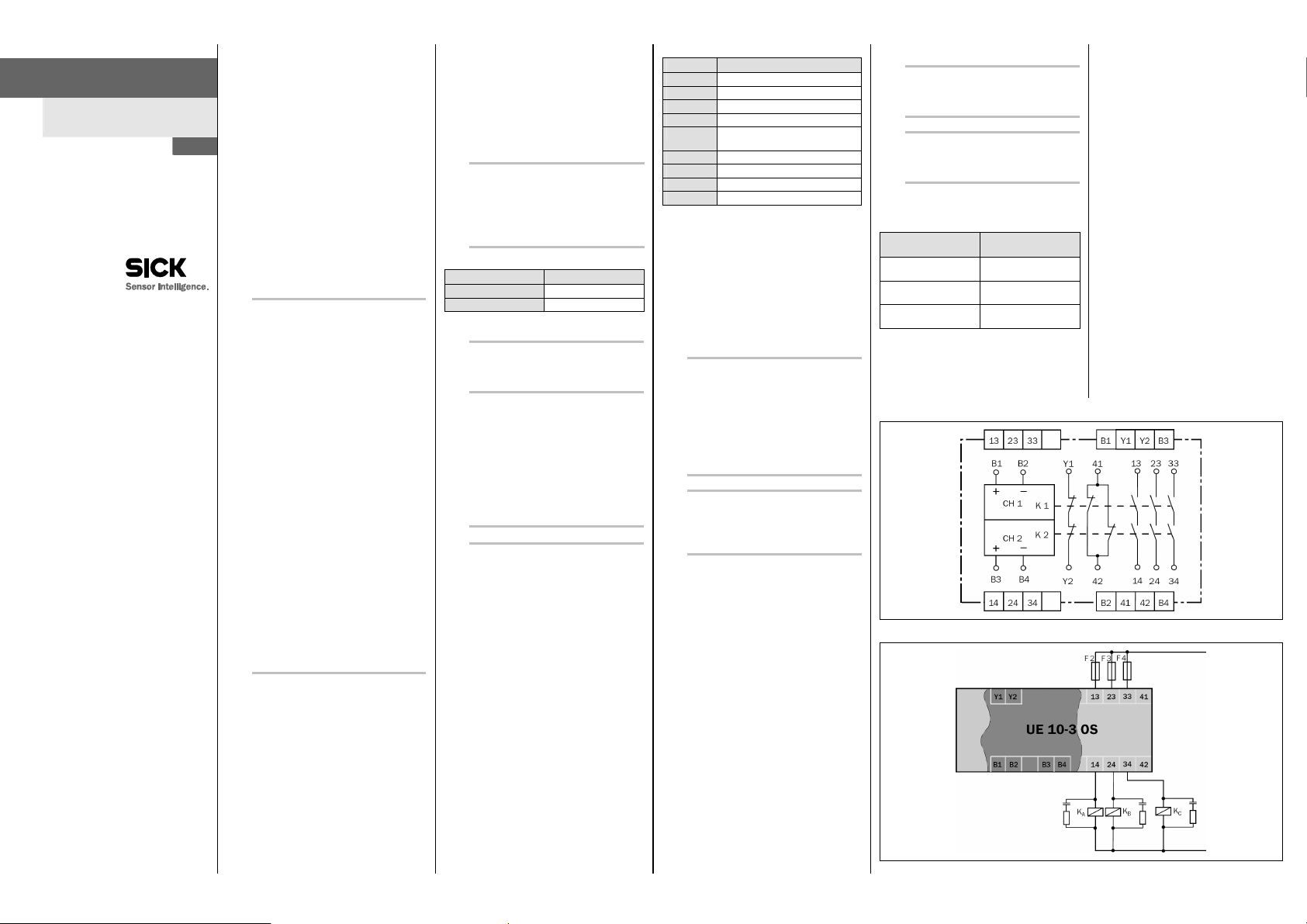
Klemmen-Belegung
Klemme Beschreibung
B1 Eingangskreis 1
B3 Eingangskreis 2
B2 0 V
B4 0 V
Y1-Y2
Rückmeldestrompfad (zur Verwendung
als Schützkontrolle)
13-14 Freigabestrompfad 1
23-24 Freigabestrompfad 2
33-34 Freigabestrompfad 3
41-42 Meldestrompfad (nicht sicher)
Einkanaliger Betrieb
Zwischen B1 und B3 ist eine Brücke anzuschließen. Der
Halbleiterausgang des Basisgerätes ist mit B1 zu verbinden; 0 V des Basisgerätes ist an die Kontakte B2 und B4
anzuschließen.
Zweikanaliger Betrieb
Die Halbleiterausgänge des Basisgerätes sind mit B1 und
B3 zu verbinden; 0 V des Basisgerätes ist an die Kontakte
B2 und B4 anzuschließen.
6 Inbetriebnahme und
regelmäßige Prüfungen
Keine Inbetriebnahme ohne Prüfung durch eine
befähigte Person!
Bevor Sie eine durch das Erweiterungsgerät
geschützte Anlage erstmals in Betrieb nehmen,
muss die Anlage durch eine befähigte Person
überprüft und dokumentiert freigegeben werden.
Beachten Sie hierzu die Hinweise in Kapitel 2
„Zur Sicherheit“.
Beachten Sie die entsprechenden Gesetze und
nationalen Vorschriften.
Kontrollieren Sie den Gefahrbereich!
S tellenSie vor der Inbetriebnahme sicher, dass
sich niemand im Gefahrbereich aufhält.
S ichernSie den Gefahrbereich gegen das
Betreten durch Personen ab.
Regelmäßige Prüfung der Schutzeinrichtungen durch
befähigte Personen
Pr üfenS iedie Anlage entsprechend den national gülti-
gen Vorschriften innerhalb der darin geforderten Fristen.
– JedeSicherheitsapplikation muss in einem von Ihnen
festgelegten Zeitintervall überprüft werden.
– DieWirksamkeit der Schutzeinrichtungen muss durch
befugte und beauftragte Personen geprüft werden.
Wenn Änderungen an der Maschine oder der Schutzein-
richtung durchgeführt wurden oder das Erweiterungsgerät
umgerüstet oder instand gesetzt wurde, dann müssen
Sie die gesamte Sicherheitsapplikation erneut prüfen.
7 Verhalten im Fehlerfall
Kein Betrieb bei unklarem Fehlverhalten!
S etzenSie die Maschine außer Betrieb, wenn Si
den Fehler nicht eindeutig zuordnen können und
nicht sicher beheben können.
Vollständiger Funktionstest nach
Fehlerbeseitigung!
Führen Sie nach der Beseitigung eines Fehlers
einen vollständigen Funktionstest durch.
8 Bestelldaten
8.1 Systeme
Artikel Artikelnummer
UE103OS für 24 V DC
mit Schraubklemmen
UE103OS für 24 V DC
mit Steckblockklemmen
UE10-3OS für 24 V DC
mit Zugfederklemmen
(Typenschlüssel)
6024917
(UE10-3OS2D0)
6024918
(UE10-3OS3D0)
1028303
(UE10-3OS4D0)
10 Schaltbild
Abb. 1: Schaltbild UE103OS
Abb. 2: Basisbeschaltung UE103OS
9 Konformität mit
EU;Richtlinien
EU-Konformitätserklärung (Auszug)
Der Unterzeichner, der den nachstehenden Hersteller
vertritt, erklärt hiermit, dass das Produkt in Übereinstimmung mit den Bestimmungen der nachstehenden
EU-Richtlinie(n) (einschließlich aller zutreffenden
Änderungen) ist, und dass die entsprechenden Normen und/oder technischen Spezifikationen zugrunde
gelegt sind.
Vollständige EU-Konformitätserklärung zum Download:
www.sick.com
Page 2
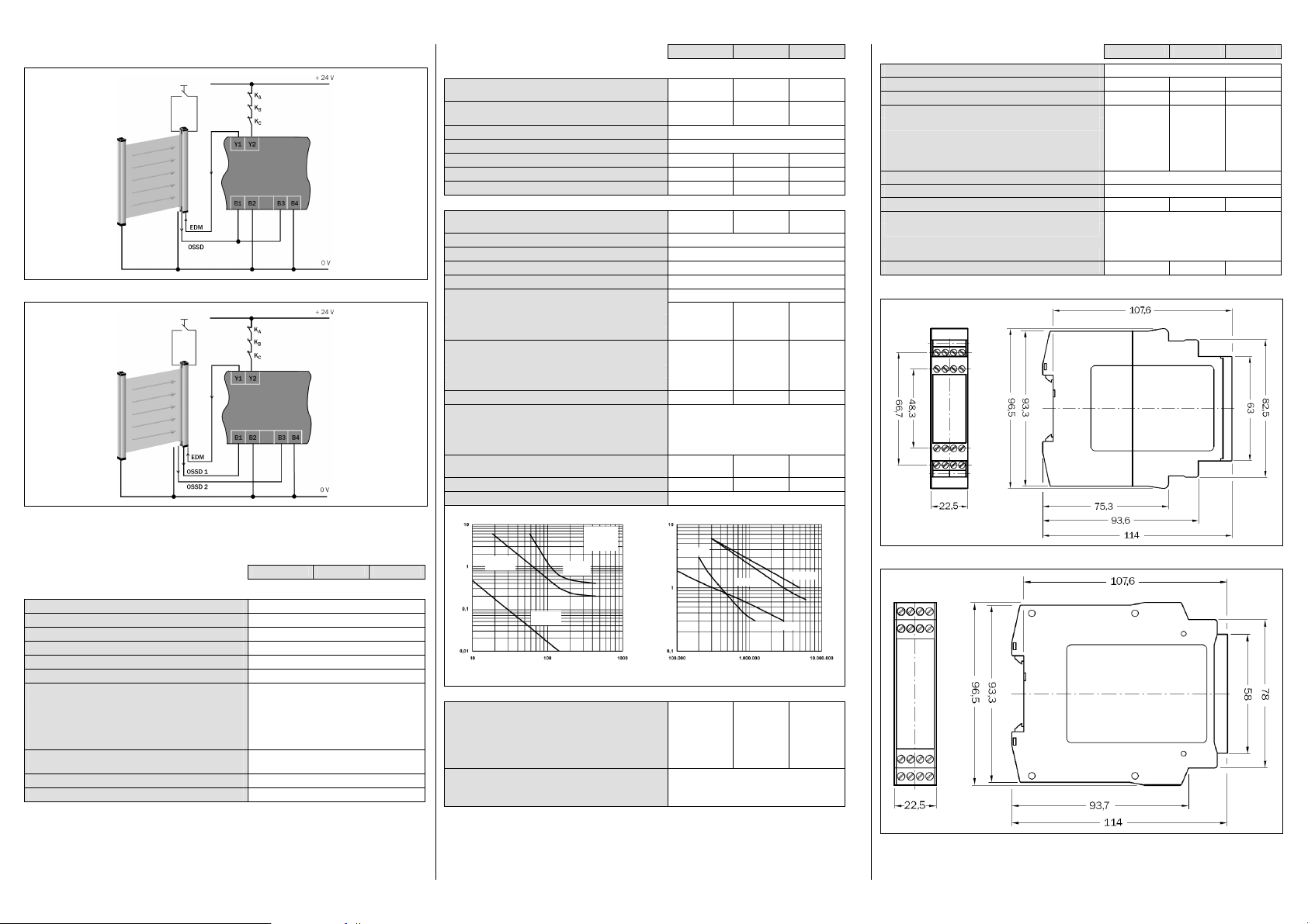
11 Applikationsbeispiele
Schaltstrom (A)
Schaltstrom (A)
Kontaktabstand:
AC-15:2 30VDC-
13:2 4V
DC-1:24 V
AC-1:23 0V
Abb. 3: Beispiel einkanaliger Lichtvorhang Typ 2 mit manueller Rücksetzung und Schützkontrolle
Abb. 4: Beispiel zweikanaliger Lichtvorhang Typ 4 mit manueller Rücksetzung und Schützkontrolle
12 Technische Daten
12.1 Datenblatt
Minimal Typisch Maximal
Allgemeine Systemdaten
Sicherheits-Integritätslevel
SIL-Anspruchsgrenze
Safe failure fraction (SFF) 90 % (EN 62061)
Hardware-Fehlertoleranz (HFT) 1 (EN 62 061)
Kategorie Kategorie 4 (EN ISO 13 849)
Performance Level
B
-Wert (Relais)
10d
AC15, 230 V, I = 1,5 A
AC15, 230 V, I = 0,75 A
DC13, 24 V, I = 2,5 A
DC13, 24 V, I = 0,63 A
PFHd (mittlere Wahrscheinlichkeit eines Gefahr bringenden
Ausfalls pro Stunde)
TM(Gebrauchsdauer) 20 Jahre (EN ISO 13 849)
Stoppkategorie 0/13)(EN 60 2041)
1)
1)
1)
2)
SIL3 (IEC 61 508)
SILCL3 (EN 62 061)
PL e (EN ISO 13 849)
6
Schaltspiele
1,26 × 10
6
Schaltspiele
5,9 × 10
3
Schaltspiele
435 × 10
6
10 × 10
Schaltspiele
–8
3 × 10
Minimal Typisch Maximal
Versorgungsspannung/Eingangskreis (B1-B2/B3-B4)
Eingangsspannung (B1-B2/B3-B4),
Nennspannung 24 V DC
Für UL-/CSA-Anwendungen:
Input voltage (B1-B2/B3-B4)
Ausgangsstrompfade > 25 V AC/60 V DC
Ausgangsstrompfade 25 V AC/60 V DC
Leistungsaufnahme (Gesamtleistung)
Einschaltstrom
15 V 24 V 30 V
24 V DC
PELV an B1-B2/B3-B4
SELV oder PELV an B1-B2/B3-B4
2 ×1,2 W
500 mA
Einschaltzeit (B1-B2/B3-B4)
Ausgangsstrompfade (13/14, 23/24, 33/34, 41/42, Y1/Y2)
Rückfallverzögerungszeit K1/K2
(Ansprechzeit Schutzfunktion)
Kontaktwerkstoff und Oberfläche
Freigabestrompfade (Schließer), sicherheitsrelevant
Meldestrompfade (Öffner), nicht sicherheitsrelevant
Rückmeldestrompfade (Öffner, Schützkontrolle)
Ag Sn O2+ 2 µm Au
3
1
1
16 ms 20 ms
Kontaktart Zwangsgeführt
Kontaktbelastbarkeit Rückmeldestrompfad (Y1, Y2)
Schaltspannung DC 10 V 24 V
Schaltstrom 5 mA 100 mA
Kontaktbelastbarkeit (siehe Diagramm)
Schaltspannung AC 10 V 230 V AC
Schaltspannung DC 10 V 300 V DC
Schaltstrom 5 mA 6 A
Summenstrom
Gebrauchskategorie (EN 60 947-5-1)
AC-15 Ue 230 V AC, Ie 4 A (360 Sch/h)
AC-15 Ue 230 V AC, Ie 3 A (3600 Sch/h)
DC-13 Ue 24 V DC, Ie 4 A (360 Sch/h)
DC-13 Ue 24 V DC, Ie 2,5 A (3600 Sch/h)
Kontaktabsicherung gG bzw.
Leitungsschutzschalter der Charakteristik B oder C
Zulässige Schalthäufigkeit
Lebensdauer mechanisch
7
10
Schaltspiele
3600/h
DC-Ausschaltvermögen Elektrische Lebensdauer
1,2mm
:Lichtbogen-
t
LB
L/R= 40 ms
t
>5 ms
LB
L/R= 40 ms
<5 ms
t
LB
brenndauer
L/R= 0 ms
<5 ms
t
LB
Schaltspannung (V DC)
Schaltspiele
Betriebsdaten
Berührungsschutz (EN 60 6641, EN 609471)
Bemessungsstoßspannung U
Überspannungskategorie
Bemessungsspannnung
Prüfspannung U
Imp
50 Hz
eff
4 kV
4)
II
300 V AC
2 kV
Schutzart
Gehäuse IP 40 (EN 60 529)
Klemmen IP 20 (EN 60 529)
40 ms
12 A
6 A
Minimal Typisch Maximal
Montage Hutschiene (EN 60 715)
Betriebsumgebungstemperatur
Lagertemperatur
–25 °C +55 °C
–25 °C +75 °C
Leiterquerschnitte
Eindraht (1×)
Eindraht (2×, gleicher Querschnitt)
Feindrahtig mit Aderendhülsen (1×)
Feindrahtig mit Aderendhülsen (2×, gleicher Querschnitt)
0,14 mm² 2,5 mm²
0,14 mm² 0,75 mm²
0,25 mm² 2,5 mm²
0,2 mm² 0,5 mm²
Störaussendung EN 61 00064
Störfestigkeit EN 61 00062
Zulässiges Anzugsdrehmoment
Für UL 508- und CSA-Anwendungen
Anschlussquerschnitt AWG 26-14
Anzugsdrehmoment 5-7 lb in
(nur 60/75 °C-Kupferlitzen verwenden)
Gewicht
12.2 Maßbilder
Abb. 5: Maßbild UE10-3OS mit Schraubklemmen
0,5 Nm 0,6 Nm
200 g
1)
Für detaillierte Informationen zur Sicherheitsauslegung Ihrer Maschine/Anlage setzen Sie sich bitte mit Ihrer
zuständigen SICK-Niederlassung in Verbindung.
2)
Bei DC = 99% und MTTFd = 100 a (gemäß EN ISO 13849, Tab. K1 und Formel C.7) und 8760 Schaltspielen/a.
3)
In Abhängigkeit vom Basisgerät, z.B. angeschlossene BWS.
4)
Zum Erreichen der Überspannungskategorie III siehe Hinweis in Kapitel 5.
Abb. 6: Maßbild UE10-3OS mit Steckblockklemmen
Page 3

O PE R A T IN G I N S T R U C T I ON S
apply to the installation, commissioning, use and
In order to attain SIL3/PL e, connect the external
UE10-3OS
Expansion module for basic
devices
en
SICK AG • Industrial Safety Systems
ErwinSick-Straße 1
D-79183 Waldkirch • www.sick.com
8009656/YSS0/2016-03-17 • REIPA/XX
Printed in Germany (2016-03) • All rights reserved •
Subject to change without notice
1 Scope
These operating instructions are only applicable to the
UE103OS basic device expansion modules with the
following entry on the type label in the field Operating
Instructions: 8009656
You will find the device’s date of manufacture on the
type label in the field Date Code in the format yywwxxxx
(yy = year, ww = calender week, xxxx = serial number).
These operating instructions are original operating
instructions.
2 On safety
This chapter deals with your own safety and the safety
of the equipment operators.
Please read this chapter carefully before working
with the UE103OS or with the machine protected
by the UE103OS.
2.1 Qualified safety personnel
The UE103OS expansion module must only be
installed, commissioned and serviced by qualified
safety personnel.
Qualified safety personnel are defined as persons
who …
have undergone the appropriate technical training
and
have been instructed by the responsible machine
operator in the operation of the machine and the
current valid safety guidelines and
have access to the operating instructions of the
UE103OS expansion module and have read and
familiarised themselves with them.
2.2 Applications of the device
The UE103OS expansion module can be used:
in accordance with EN ISO 13 849 up to PL e and
category 4
in accordance with EN 62 061 to SILCL3
in accordance with IEC 61 508 up to SIL3
The actual performance level or SIL claim limit achieved depends on the external circuit, the design of the
wiring, the selection of the control switch and its placement on the machine.
The UE10-3OS expansion module has been evaluated
to UL 508.
The UE103OS expansion module is used for:
electro-sensitive protective equipment (ESPE) with mo-
nitored active output signal switching device (OSSD):
single-channel, dual-channel (in accordance with
IEC 61 4961)
safety devices with monitored semiconductor outputs,
e.g. Flexi Classic and Flexi Soft
The UE103OS has no restart interlock and no external
device monitoring.
2.3 Correct use
The UE103OS expansion module must be used only as
defined in section 2.2 “Applications of the device”.
It must be used only by qualified safety personnel and only
on the machine where it has been installed and initialised
by qualified safety personnel in accordance with the operating instructions. If the device is used for any other purposes
or modified in any way — also during mounting and installation — any warranty claim against SICK AG shall become
void.
2.4 General safety notes and protective
measures
Pay attention to the safety notes and protective
measures!
Please observe the following items in order to ensure the correct use of the UE103OS expansion
module.
During the mounting, installation and usage of
the expansion module, observe the standards
and directives applicable in your country.
The national/international rules and regulations
periodic technical inspection of the expansion
module, in particular:
– Machinery Directive
– WorkEquipment Directive
– EMCdirective
– thework safety regulations and safety rules
Manufacturers and operators of the machine on
which a expansion module is used are responsible for obtaining and observing all applicable
safety regulations and rules.
The tests must be carried out by qualified safety
personnel or specially qualified and authorised
personnel and must be recorded and documented to ensure that the tests can be reproduced
and retraced at any time by third parties.
The operating instructions must be made avai-
lable to the operator of the machine where the
UE103OS is used.
The machine operator is to be instructed in the
use of the device by qualified safety personnel
and must be instructed to read the operating
instructions.
2.5 Environmental protection
Disposal of unusable or irreparable devices must always
occur in accordance with the applicable country-specific
waste-disposal regulations (e.g. European Waste Code
16 02 14).
3 Product description
The related actuators on the machine or system can be
safely shut down using the expansion module’s output
signal switching contacts.
The switching of the semiconductor outputs on the upstream basic devices controls the internal relays via the two
separate input circuits. The enable current paths are used
as safe outputs. The signalling current path is not a safe
output. The feedback current path is used as external
device monitoring for the monitoring by the basic device.
device monitoring!
In order to reach SIL3/PL e, an external diagnosis
with DC K 99 % must be applied (i.e. the external
device monitoring must be connected).
Please also read the notes in chapter 11
“Application examples”.
Status indicators
Display Meaning
K1 Green Channel 1 switched
K2 Green Channel 2 switched
4 Mounting
Mounting only with enclosure rating IP 54 or
better!
The expansion module is only allowed to be mounted in the control cabinet. The control cabinet must
at least comply with enclosure rating IP 54.
Mounting in accordance with EN 50 274.
The modules are located in a 22.5 mm wide modular
system for 35 mm mounting rails as per EN 60 715.
5 Electrical installation
Note:
All external switching elements and their wiring must
withstand an ampacity, maximal short-circuit load of
I
= 1000 A (according to EN 60947-5-1).
max
Switch the entire machine/system off line!
The voltage supply must satisfy the regulations for extra-
low voltages with safe isolation (SELV, PELV) for overvoltage category II as per EN 60 664 and EN 50178.
Note:
Overvoltage category III can be achieved if the contact
circuits Y1/Y2 and 41/42 are operated in the same circuit as the upstream OSSDs (safety extra-low voltage).
For installation in environments with overvoltage category III, external protection elements must be used.
All connections, wiring and cable runs must comply with
the required category as per EN ISO 138 49 and
EN 62 061 (e.g. cableslaid with pr otection,individually
sheathed cable with screen etc.).
Always connect inputs B2 and B4 to the 0V potential of
the supply voltage for the basic devices.
To protect the contact outputs on the UE103OS and to
increase the service life, the loads connected must be
equipped with, e.g., varistors and RC circuits. Please also
note that the selection of the arc suppression can increase the total response time of the safety function.
The output signal switching devices and the external
device monitoring (EDM) must be wired in the control
cabinet.
To prevent the welding of the contacts on the built-in
relay, an overcurrent protection device with max. 6 A
short-circuit protection (duty class gG) is to be integrated
into the current paths (see Fig. 2, enable current path
fuse F2/F3/F4).
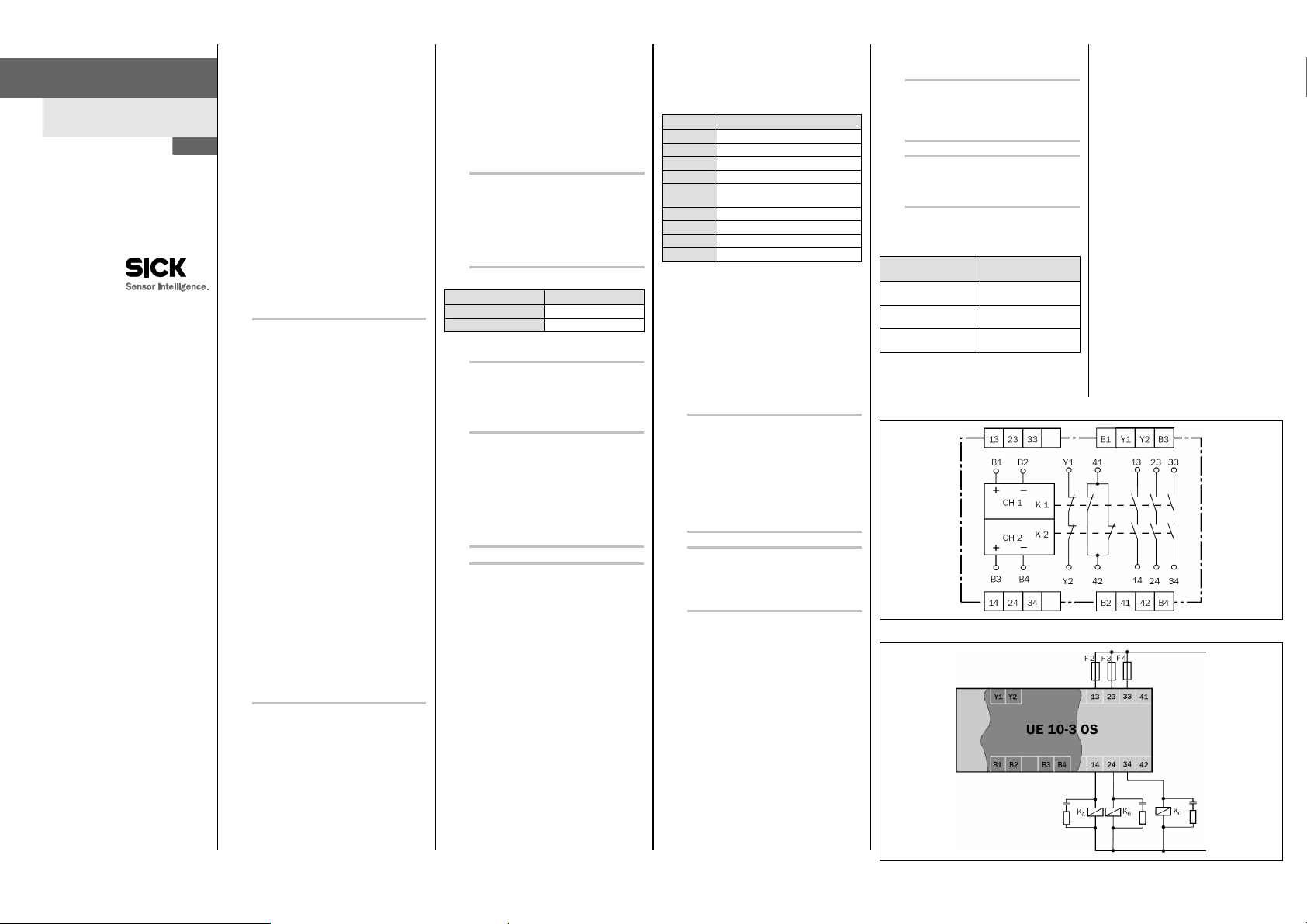
Pin assignments
Terminal Description
B1 Input circuit 1
B3 Input circuit 2
B2 0 V
B4 0 V
Y1-Y2
Feedback current path (for usage as
external device monitoring)
13-14 Enable current path 1
23-24 Enable current path 2
33-34 Enable current path 3
41-42 Signalling current path (not safe)
Single-channel operation
A jumper is to be connected between B1 and B3. The semiconductor output on the basic device is to be connected to
B1; 0 V on the basic device is to be connected to the contacts B2 and B4.
Dual-channel operation
The semiconductor outputs on the basic device are to be
connected to B1 and B3; 0 V on the basic device is to be
connected to the contacts B2 and B4.
6 Commissioning and regular
tests
Commissioning requires a thorough check by
qualified safety personnel!
Before you operate a system protected by the
expansion module for the first time, make sure that
the system is first checked and released by
qualified safety personnel.
Please read the notes in chapter 2 “On safety”.
Obs ervet herelevant laws and national
regulations.
Check the hazardous area!
Ens uret hereis nobody in the hazardous area
before commissioning.
S ecurethe hazardous area against entry.
Regular inspection of the protective devices by qualified
safety personnel
C heckthe system following the inspection intervals
specified in the national rules and regulations.
– Eachsafety application must be checked at an interval
specified by you.
– Theeffectiveness of the protective devices must be
checked daily by a specialist or by authorised
personnel.
If changes have been made to the machine or the pro-
tective device, or the expansion module has been
changed or repaired, you must again thoroughly check
the entire safety application.
7 In the event of faults or errors
Cease operation if the cause of the malfunction
has not been clearly identified!
S top them achineif you cannot clearly identify or
allocate the error and if you cannot safely rectify
the malfunction.
Complete function test after rectification of
fault!
Af ter rectifyinga fault, perform a complete
function test.
8 Ordering information
8.1 Systems
Part Part number
UE103OS for 24 V DC
with screw type terminals
UE103OS for 24 V DC
with removable terminals
UE10-3OS for 24 V DC
with spring terminals
(type code)
6024917
(UE10-3OS2D0)
6024918
(UE10-3OS3D0)
1028303
(UE10-3OS4D0)
10 Internal circuitry
Fig. 1: Internal circuitry UE103OS
9 Compliance with EU
directives
EU declaration of conformity (excerpt)
The undersigned, representing the following manufacturer herewith declares that the product is in conformity
with the provisions of the following EU directive(s)
(including all applicable amendments), and that the
respective standards and/or technical specifications
are taken as the basis.
Complete EU declaration of conformity for download:
www.sick.com.
Fig. 2: Basic circuit UE103OS
Page 4

11 Application examples
Switching cu rrent (A)
Switching cu rrent (A)
Contact clearance:
AC-15:2 30VDC-
13:2 4V
DC-1:24 V
AC-1:23 0V
Fig. 3: Example of single-channel light curtain type 2 with manual reset and external device monitoring
Fig. 4: Example of dual-channel light curtain type 4 with manual reset and external device monitoring
12 Technical specifications
12.1 Data sheet
Minimum Typical Maximum
General system data
Safety integrity level
SIL claim limit
Safe failure fraction (SFF) 90 % (EN 62061)
Hardware fault tolerance (HFT) 1 (EN 62 061)
Category Category 4 (EN ISO 13 849)
Performance Level
B
value (relay)
10d
AC15, 230 V, I = 1.5 A
AC15, 230 V, I = 0.75 A
DC13, 24 V, I = 2.5 A
DC13, 24 V, I = 0.63 A
PFHd (mean probability of a dangerous failure per hour)
TM(mission time) 20 years (EN ISO 13 849)
Stop category 0/13)(EN 60 2041)
1)
For detailed information on the safetyde sign of your machine/system, pleasec ontact your local SICK representative.
2)
With DC = 99% and MTTFd = 100 a (according to EN ISO 13849, Tab. K1 and formula C.7) and 8760 switching
operations/a.
3)
Depending on the basic device, e.g. ESPEconnected.
1)
1)
1)
2)
SIL3 (IEC 61 508)
SILCL3 (EN 62 061)
PL e (EN ISO 13 849)
6
switching operations
1.26 × 10
6
switching operations
5.9 × 10
3
switching operations
435 × 10
6
10 × 10
switching operations
–8
3 × 10
Minimum Typical Maximum
Supply voltage/input circuit (B1-B2/B3-B4)
Input voltage (B1-B2/B3-B4),
nominal voltage 24 V DC
For UL/CSA applications:
Input voltage (B1-B2/B3-B4) 24 V DC
Output current circuits >25 V AC/60 V DC
Output current circuits 25 V AC/60 V DC
15 V 24 V 30 V
PELV at B1-B2/B3-B4
SELV or PELV on B1-B2/B3-B4
Power consumption (total power) 2 ×1.2 W
Switch on current 500 mA
Power-up delay (B1-B2/B3-B4) 40 ms
Output current circuits (13/14, 23/24, 33/34, 41/42, Y1/Y2)
Reactivation delay K1/K2
(response time of the protective function)
16 ms 20 ms
Contact material and surface finish Ag Sn O2+ 2 µm Au
Enable current paths (normally open contact), safety relevant 3
Signalling current paths (normally closed contact), not safetyrelevant
Feedback current paths (normally closed contact, external
device monitoring)
1
1
Contact type Positively guided
Max. contact load, feedback current path (Y1, Y2)
Switching voltage DC 10 V 24 V
Switching current 5mA 100 mA
Max. contact load (see diagram)
Switching voltage AC 10 V 230 V AC
Switching voltage DC 10 V 300 V DC
Switching current 5mA 6 A
Total current 12 A
Usage category (EN 609 47-5-1)
Contact fuse protection gG or circuit breaker with
characteristic B or C
AC-15 Ue 230 V AC, Ie 4 A (360 switching
operations/h)
AC-15 Ue 230 V AC, Ie 3 A (3600 switching
operations/h)
DC-13 Ue 24 V DC, Ie 4 A (360 switching
operations/h)
DC-13 Ue 24 V DC, Ie 2.5 A (3600 switching
operations/h)
Permissible switching frequency 3600/h
Service life, mechanical 107switching operations
DC contact current-breaking capacity Service life, electrical
1.2mm
t
:Arc duration
LB
L/R= 40 ms
>5 ms
t
LB
L/R= 40 ms
t
<5 ms
LB
L/R= 0 ms
<5 ms
t
LB
Switching voltage (V DC)
Switching operations
Operating data
Protection against physical contact (EN 60 6641,
EN 60 9471)
Rated impulse voltage V
Overvoltage category
Rated voltage
Test voltage U
4)
To achieve overvoltage category III see notein chapter 5.
Imp
50 Hz
rms
4 kV
4)
II
300 V AC
2 kV
Minimum Typical Maximum
Enclosure rating
Housing IP 40 (EN 60 529)
Terminals IP 20 (EN 60529)
Mounting Mounting rail (EN 60 715)
Ambient operating temperature
Storage temperature
–25 °C +55 °C
–25 °C +75 °C
Wire cross-sections
Single wire (1×)
Single wire (2×, same cross-section)
Fine stranded wire with ferrules (1×)
Fine stranded wire with ferrules (2×, same cross-section)
0.14 mm² 2.5 mm²
0.14 mm² 0.75 mm²
0.25 mm² 2.5 mm²
0.2 mm² 0.5 mm²
Radiated emissions EN 61 00064
Interference resistance EN61 00062
Allowed tightening torque
For UL 508 and CSA applications
Connection cross-section AWG 26-14
Tightening torque 5-7 lb in
(only use 60/75 °C copper flexible wire)
Weight
0.5 Nm 0.6 Nm
200 g
12.2 Dimensional drawings
6 A
Fig. 5: Dimensional drawing UE10-3OS with screw type terminals
Fig. 6: Dimensional drawing UE10-3OS with removable terminals
Page 5
N OT I CE D ’I N ST R U C T I ON S
d’extension ainsi que pour son mise en service et
UE10-3OS
Module d’extension pour
modules principaux
fr
SICK AG • Industrial Safety Systems
ErwinSick-Straße 1
D-79183 Waldkirch • www.sick.com
8009656/YSS0/2016-03-17 • REIPA/XX
Printed in Germany (2016-03) • Tous droits réservés •
Sujet à modification sans préavis
1 Disponibilité des fonctions
Cette notice d’instructions concerne les modules
d’extension UE103OS pour modules principaux
comportant la mention suivante sur le champ
Operating Instructions de la plaque signalétique :
8009656
La date de fabrication du module est indiquée sur la
plaque signalétique dans le champ Date Code format
aassxxxx (aa = année, ss = n° de semaine, xxxx =
numéro de série).
Cette notice d’instructions est une traduction de la
notice d’instructions d’origine.
2 La sécurité
Ce chapitre est essentiel pour la sécurité tant des
installateurs que des opérateurs de l’installation.
L ireimpérativement ce chapitre avec attention avant
de commencer à mettre en œuvre l’UE103OS ou la
machine protégée par l’UE103OS.
2.1 Personnel qualifié
Le module d’extension UE103OS ne doit être monté,
installé, mis en service et verifié que par un personnel
qualifié.
Sont qualifiées les personnes qui …
ont reçu la formation technique appropriée et
ont été formées par l’exploitant à l’utilisation de
l’équipement et aux directives de sécurité en vigueur
applicables et
ont accès à la notice d’instructions du module
d’extension UE103OS et l’ont lue et assimilée.
2.2 Domaine d’utilisation de l’appareil
Le module d’extension UE103OS peut être mis en
œuvre :
selon EN ISO 13 849 jusqu’au niveau de
performance PL e et la catégorie 4
selon EN 62 061 jusque SILCL3
selon CEI 61 508 jusque SIL3
Le «Performance Level» (niveau de performance)
effectivement atteint ou l’indice SIL limite atteint
dépendent du schéma externe, de la version du
câblage, du choix de l’organe de commande et de la
façon dont il est raccordé sur place à la machine.
Le module d’extension UE10-3OS a été testé selon la
norme UL 508.
Le module d’extension UE103OS est utilisé dans le cadre
de :
équipements de protection électrosensible (ESPE) avec
sorties TOR actives (OSSD) surveillées : monovoie, bivoie
(selon CEI 61 4961)
modules de sécurité à sorties statiques autocontrôlées,
par ex. Flexi Classic et Flexi Soft
L’UE103OS ne dispose pas du verrouillage de redémarrage ni du contrôle des contacteurs commandés.
2.3 Conformité d’utilisation
Le rmodule d’extension UE103OS ne peut être utilisé que
dans les domaines décrits au paragraphe 2.2 «Domaine
d’utilisation de l’appareil».
Il ne peut en particulier être mis en œuvre que un personnel
qualifié et seulement sur la machine sur laquelle il a été
installé et mis en service initialement par une personne
qualifiée à cet effet selon les prescriptions de cette notice
d’instructions. Pour toute autre utilisation, aussi bien que
pour les modifications – y compris concernant le montage
et l’installation – la responsabilité de la société SICK AG ne
saurait être invoquée.
2.4 Consignes de sécurité et mesures de
protection d’ordre général
Respecter les consignes de sécurité et les
mesures de protection !
Pour garantir la conformité d’utilisation du module
d’extension UE103OS il faut observer les points
suivants.
Il faut s’assurer que le montage, l’installation et
l’utilisation du module d’extension sont conformes aux normes et à la réglementation du pays
d’exploitation.
Pour le montage et l’exploitation du module
les tests réguliers il faut impérativement
appliquer les prescriptions légales nationales et
internationales et en particulier :
– ladirective machine
– ladirective d’utilisation des installations
– ladirective CEM
– lesprescriptions de prévention des accidents
et les règlements de sécurité
Le fabricant et l’exploitant de la machine à qui
est destiné le module d’extension sont responsables de l’application stricte de toutes les prescriptions et règles de sécurité en vigueur.
Les tests doivent être exécutés par un personnel
qualifié et/ou des personnes spécialement autorisées/mandatées ; ils doivent être documentés
et cette documentation doit être disponible à
tout moment.
La notice d’instructions doit être mise à dispo-
sition de l’opérateur de la machine sur laquelle
l’UE103OS est mis en œuvre.
L’opérateur de la machine doit être formé par un
personnel qualifié et prendre connaissance de
cette notice d’instructions.
2.5 Pour le respect de l’environnement
L’élimination des appareils mis au rebut ou irréparables
doit toujours être effectuée dans le respect des prescriptions concernant l’élimination des déchets (par ex. Code
européen des déchets 16 02 14).
3 Description du produit
Via les sorties TOR à contact du module d’extension, on
peut produire un arrêt de sécurité des actionneurs correspondants de la machine ou de l’installation.
La commutation des sorties statiques à semi-conducteurs
du module principal câblé en commande des relais internes via deux circuits d’entrée séparés. Les contacts de
commande servent de sortie de sécurité. Le contact d’état
n’est pas une sortie de sécurité. Le contact de retour sert de
contrôle des contacteurs commandés pour la surveillance
via le module principal.
Pour atteindre le niveau SIL3/PL e, raccorder le
contrôle des contacteurs commandés !
Pour atteindre le niveau SIL3/PL e, il faut utiliser un
diagnostic externe avec DC T 99 % (c.-à-d. que le
contrôle des contacteurs commandés doit être
raccordé).
À cet effet, observer également les instructions du
chapitre 11 «Exemples d’applications».
Indicateurs
Indication Interprétation
K1 Vert Voie 1 commutée
K2 Vert Voie 2 commutée
4 Montage
Montage uniquement avec indice de protection
IP 54 ou plus !
Il est obligatoire de monter le module d’extension
dans une armoire électrique. L’armoire électrique
doit satisfaire au moins à l’indice de protection
IP 54.
Montage selon EN 50 274.
L esm oduless ont intégrésd ans des boîtiers de2 2,5mm
de large pour rail normalisé de 35 mm selon EN 607 15.
5 Installation électrique
Remarque :
Tous les contacteurs externes et leur câblage doivent
résister à une ampacité, courant de court-circuit
I
= 1000 A (selon EN 60947-5-1).
max
Mettre l’installation hors tension !
L’alimentation doit répondre à la réglementation basse
tension avec isolement de protection (TBTS, TBTP) pour la
catégorie II de surtension selon EN 60 664 et EN 50178.
Remarque :
La catégorie de surtension III peut être atteinte si les
circuits des contacts Y1/Y2 et 41/42 et les OSSD sont
exploité dans un circuit d’alimentation commun (très
basse tension de sécurité). Pour les installations dans un
environnement de catégorie III de surtension, il est obligatoire d’utiliser des éléments de protection externe.
Tous les raccordements ainsi que le câblage et les
chemins de câble doivent être conformes à la catégorie
selon EN ISO 13 849 et selon EN 62061 (par ex. chemins de câble protégés, conducteurs en gaine individuelle avec blindage, etc.).
Toujours relier les entrées B2 et B4 au potentiel 0 V de la
tension d’alimentation du module principal.
Afin de protéger les contacts de sortie de l’UE103OS et
d’augmenter leur durée de vie, les charges externes raccordées doivent être antiparasitées par ex. par des varistors et des cellules RC. Observer que ces équipements
selon leur nature augmentent plus ou moins le temps de
réponse.
Les sorties de sécurité et le contrôle des contacteurs
commandés (EDM) doivent être câblés à l’intérieur
même de l’armoire.
Pour empêcher que les contacts des relais intégrés ne se
soudent, il faut installer dans les circuits une protection
contre les surintensités protégeant des courts-circuits de
6A max. (classe de service gG) (cf. Fig. 2, sécurité des
contacts de commande F2/F3/F4).
Affectation des bornes
Borne Description
B1 Circuit d’entrée 1
B3 Circuit d’entrée 2
B2 0 V
B4 0 V
Y1-Y2
Contact de retour (à utiliser comme
contrôle des contacteurs commandés)
13-14 Contact de commande 1
23-24 Contact de commande 2
33-34 Contact de commande 3
41-42 Contact d’état (ordinaire)
Service monovoie
Il faut câbler un cavalier entre B1 et B3. La sortie statique (à
semi-conducteurs) du module principal doit être reliée à
B1 ; le 0 V du module principal doit être relié aux contacts
B2 et B4.
Service bivoie
Les sorties statiques du module principal doivent être
reliées à B1 et B3 ; le 0 V du module principal doit être relié
aux contacts B2 et B4.
6 Mise en service et contrôles
périodiques
Un personnel qualifié doit effectuer des tests de
validation pour que la mise en service soit
effective !
Un personnel qualifié doit tester et valider dans un
rapport l’installation protégée par un module
d’extension, avant sa première mise en service.
Dans ce but, observer les conseils prodigués
chapitre 2 «La sécurité».
Il faut respecter la législation correspondant eet
les prescriptions nationales.
Contrôler la zone dangereuse !
Av ant lamise en service, il faut s’assurer que
personne ne se trouve dans la zone dangereuse.
Faire en sorte que personne ne puisse pénétrer
dans la zone dangereuse.
Un personnel qualifié doit effectuer un test régulier des
équipements de protection
Il faut effectuer des tests en temps voulu en conformité
avec les prescriptions nationales en vigueur.
– Chaqueapplication de sécurité doit être contrôlée à
intervalle régulier fixé par l’exploitant.
– L’efficacité de l’équipement de protection doit être
vérifiée chaque jour par un personnel autorisé et dont
c’est la mission.
L orsque des modificationss ont effectuéess urla machi-
ne ou sur l’équipement de protection, ou encore en cas
de modification ou de réparation du module d’extension,
il est nécessaire de contrôler de nouveau l’ensemble de
l’application de sécurité.
7 Comportement en cas de
défaillance
Ne jamais travailler avec un système dont la
sécurité pourrait être mise en doute !
Mettr ela machine hors serv icesi la défaillance
ne peut pas être identifiée ni éliminée avec
certitude.
Effectuer un test complet après l’élimination
d’un défaut !
Ap rès éliminationd’un défaut, il faut effectuer un
test fonctionnel complet.
8 Références
8.1 Systèmes
Article Référence
UE103OS pour 24 V CC
à borniers à vis
UE103OS pour 24 V CC
à borniers enfichables
UE10-3OS pour 24 V CC
à borniers à ressort
(désignation)
6024917
(UE10-3OS2D0)
6024918
(UE10-3OS3D0)
1028303
(UE10-3OS4D0)
10 Schéma de câblage
Fig. 1 : Schéma de câblage UE10!3OS
9 Conformité aux directives UE
Déclaration de conformité UE (extrait)
Le soussigné, représentant le constructeur ci-après,
déclare par la présente que le produit est conforme aux
exigences de la (des) directive(s) de l’UE suivantes (y
compris tous les amendements applicables) et que les
normes et/ou spécifications techniques correspondantes ont servi de base.
Pour télécharger la Déclaration UE de conformité dans
son intégralité : www.sick.com.
Fig. 2 : Schéma de base UE10!3OS
Page 6
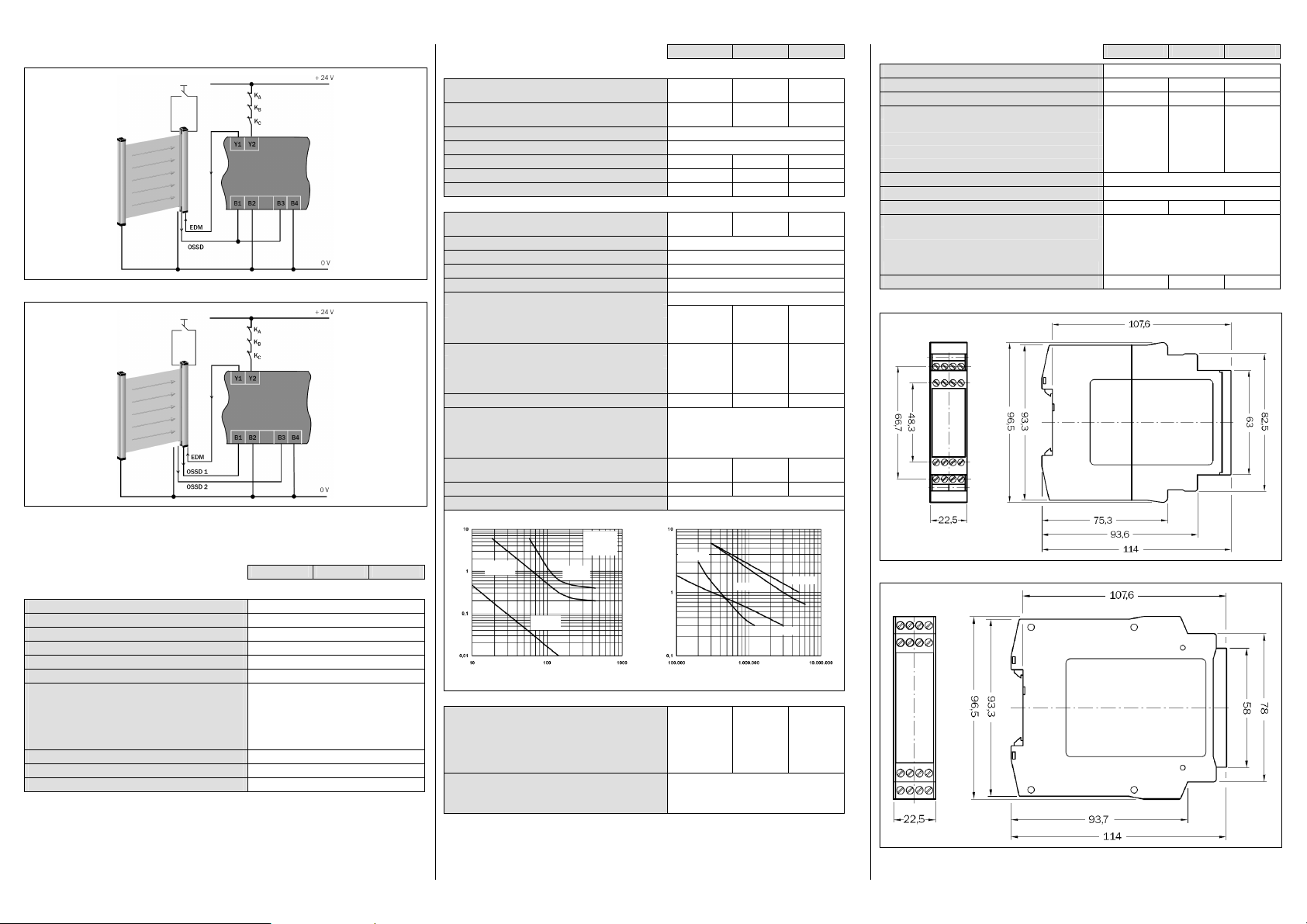
11 Exemples d’applications
Courant de commutation (A)
Courant de commutation (A)
CA-15:2 30VCC-
13:2 4V
CC-1:24 V
CA-1:23 0V
Fig. 3 : Exemple monovoie, barrage de type 2 avec réarmement manuel et contrôle des contacteurs commandés
Fig. 4 : Exemple bivoie, barrage de type 4 avec réarmement manuel et contrôle des contacteurs commandés
12 Caractéristiques techniques
12.1 Fiche de spécifications
Minimum Typique Maximum
Caractéristiques générales
Niveau d’intégrité de la sécurité
Limite d’exigence SIL
Safe failure fraction (SFF) 90 % (EN 62061)
Tolérance de défaillances du matériel (HFT) 1 (EN 62 061)
Catégorie Catégorie 4 (EN ISO 13 849)
Performance Level
Valeur B
(relais)
10d
CA15, 230 V, I = 1,5 A
CA15, 230 V, I = 0,75 A
CC13, 24 V, I = 2,5 A
CC13, 24 V, I = 0,63 A
PFHd (probabilité de défaillance dangereuse par heure)
TM(durée d’utilisation) 20 ans (EN ISO 13 849)
Catégorie d’arrêt 0/13)(EN 60 2041)
1)
1)
1)
2)
SIL3 (CEI 61 508)
SILCL3 (EN 62 061)
PL e (EN ISO 13 849)
6
manœuvres
1,26 × 10
6
manœuvres
5,9 × 10
3
manœuvres
435 × 10
6
10 × 10
manœuvres
–8
3 × 10
Minimum Typique Maximum
Tension d’alimentation/circuit d’entrée (B1-B2/B3B4) Tension d’entrée (B1-B2/B3-B4),
tension nominale 24 V CC
Pour les applications UL/CSA:
Input voltage (B1-B2/B3-B4) 24 V DC
Circuits de sortie > 25 V CA/60 V CC
Circuits de sortie 25 V CA/60 V CC
15 V 24 V 30 V
TBTP (PELV) sur B1-B2/B3-B4
SELV ou PELV sur B1-B2/B3-B4
Puissance consommée (puissance totale) 2× 1,2 W
Courant de démarrage 500 mA
Retard à la mise sous tension (B1-B2/B3-B4) 40ms
Circuits de sortie (13/14, 23/24, 33/34, 41/42, Y1/Y2)
Délai de retombée des relais K1/K2
(temps de réponse de la fonction de sécurité)
16 ms 20 ms
Matériau de contact et état de surface Ag Sn O2+ 2 µm Au
Contacts de commande (contact NO), organe de sécurité 3
Contacts d’état (contact NF), organe ordinaire 1
Contact de retour (contact NF, contrôle des contacteurs) 1
Type de contact Guidé
Charge admissible par les contacts de retour (Y1, Y2)
Tension de commutation CC 10 V 24 V
Courant de commutation 5 mA 100 mA
Charge admissible (voir diagramme)
Tension de commutation CA 10 V 230 V CA
Tension de commutation CC 10 V 300 V CC
Courant de commutation 5 mA 6 A
Courant total 12 A
Catégorie d’utilisation (EN 60 947-5-1)
CA-15 Ue 230 V CA, Ie 4 A (360 cmmt/h)
CA-15 Ue 230 V CA, Ie 3 A (3600 cmmt/h)
CC-13 Ue 24 V CC, Ie 4 A (360 cmmt/h)
Fusible de protection des contacts de classe gG ou disjoncteur
de protection de caractéristique B ou C
CC-13 Ue 24 V CC, Ie 2,5 A (3600 cmmt/h)
6 A
Fréquence de commutation admissible 3600/h
Durée de vie mécanique 107manœuvres
Pouvoir de coupure CC Durée de vie électrique
Écartemententre
contacts:1,2 mm
tLB:Durée d’a rc
L/R= 40 ms
t
>5 ms
LB
L/R= 0 ms
<5 ms
t
LB
L/R= 40 ms
<5 ms
t
LB
Tension de commutation (V CC)
Manœuvres
Données opérationnelles
Protection contre le contact (EN 606 641, EN 609471)
Tension impulsionnelle de mesure U
Catégorie de surtension
Tension de mesure
Tension d’essai U
50 Hz
eff
Imp
4 kV
4)
II
300 V CA
2 kV
Indice de protection
Boîtier
Bornes
IP 40 (EN 60 529)
IP 20 (EN 60 529)
Minimum Typique Maximum
Montage Rail de montage (EN 60 715)
Température ambiante de fonctionnement –2 5°C +5 5°C
Température de stockage –25 °C +75 °C
Sections du conducteur
Un conducteur (1×)
Un conducteur (2×, section identique)
Conducteurs toronnés avec manchons (1×)
Conducteurs toronnés avec manchons (2×, section identique)
0,14 mm² 2,5 mm²
0,14 mm² 0,75 mm²
0,25 mm² 2,5 mm²
0,2 mm² 0,5 mm²
Émissions parasites EN61 00064
Immunité aux perturbations EN 61 00062
Couple de serrage admissible 0,5 Nm 0,6 Nm
Pour les applications UL 508 et CSA
Section des fils de raccordement AWG 26-14
Couple de serrage
(utiliser uniquement des conducteurs multibrins
résistants à 60/75 °C)
5-7 lb in
Poids 200 g
12.2 Schémas cotés
Fig. 5 : Schéma coté UE10-3OS à borniers à vis
1)
Pour obtenir des informations détaillées sur la conception de sécurité de la machine/installation, prendre contact avec
l’agence SICK la plus proche.
2)
Avec CC = 99% et MTTFd = 100 a (selon EN ISO 13849, tab. K1 et formule C.7) et 8760 manœuvres/a.
3)
Dépend du module de base, par ex. ESPEconnecté.
4)
Pour atteindre la catégorie III de surtension, cf. les recommandations du chapitre5.
Fig. 6 : Schéma coté UE10-3OS à borniers enfichables
 Loading...