

Page 1
COMPACT ABSOLUTE LINEAR ENCODER
WITH HIGH RESOLUTION
A
TTK70 LINEAR ENCODERS
B
C
D
E
F
G
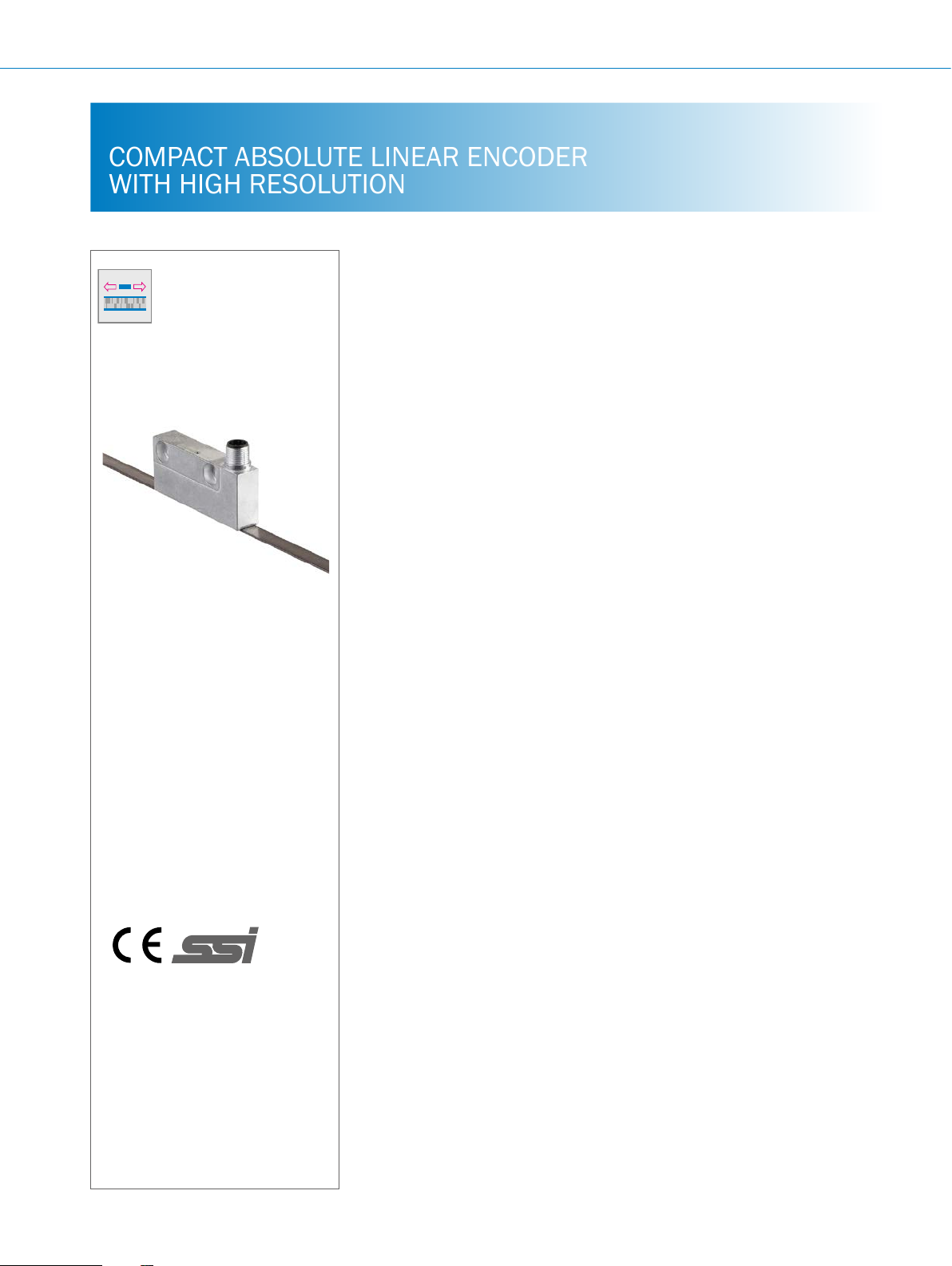
Product description
The TTK70 non-contact linear encoder
consists of a compact read head and
a magnetic tape. The magnetic tape
is equipped with a magnetic partition
and forms the measurement scale. The
partition consists of an incremental and
an absolute track (two-track tape). To
calculate the absolute position value, the
At a glance
• Non-contact absolute positioning
• Small, compact read head
• Standard SSI interface, combined
with sin/cos output
Your benets
• Easy integration into existing systems
• Small size, low weight and high
traversing speed deliver excellent
process dynamics
• After installation, the system is
immediately available and completely
maintenance-free, which leads to time
and cost savings
read head detects both the absolute and
incremental components. The position
value is directly output for further processing.
The TTK70 has an SSI output for absolute positioning and an incremental Sin/
Cos output for recording speed in real
time.
• Measuring lengths of up to 4 m
possible
• High level of accuracy (± 10 µm)
• High resolution (1 µm)
• High traversing speed of up to 10 m/s
• Immune to environmental factors
such as contamination and condensation, ensuring increased reliability
• Real-time speed determination plus
absolute positioning due to Sin/Cos
and SSI output
H
I
Additional information
J
K
L
Detailed technical data ........J- 661
Ordering information ..........J-662
Dimensional drawings .........J-663
Position tolerance.............J-663
PIN and wire allocation ........J-664
Interfaces ...................J-665
Recommended accessories ....J-666
J-660
ENCODERS | SICK 8015560/2015-09-01
Subject to change without notice
Page 2

Fields of application
• Extremely wide range of positioning tasks in mounting and
handling systems, robotics, automation, machine tool and
production systems, metal and steel processing, electronics
Detailed technical data
Performance
LINEAR ENCODERS TTK70
and solar industry, packaging industry, wood processing
industry
A
B
Measuring length
Magnetic tape length
Resolution
Period length
Traversing speed
Dynamic operation (Sin/Cos) < 10 m/s
Repeatability
System accuracy
Electrical interface
Connection type
Mechanical data
Dimensions
Mass
Material
Max. 4,000 mm
Measurement length + 80 mm
1 µm
1 mm
Static operation (SSI) < 2 m/s
Max. ± 2 µm
± 10 µm
SSI + Sin/Cos
Male connector, M12, 12-pin
See dimensional drawing
Read head 0.08 kg
Magnetic tape 0.18 kg/m
Read head Zinc die cast
Magnetic tape 17410 Hard ferrite 9/28 P
Substrate tape Stainless steel
C
D
E
F
G
Electrical data
Electrical interfaces
SSI 24 bit, gray
Sin/Cos 1 V
Supply voltage
Max. power consumption
Operating current (no load)
MTTFd: mean time to dangerous failure
1)
This product is a standard product and does not constitute a safety component as dened in the Machinery Directive. Calculation based on nominal load of devices,
average ambient temperature 40 °C, frequency of use 8,760 h/a. All electronic failures are considered hazardous. For more information, see document no.
8015532.
Subject to change without notice
1)
SS
4.5 … 30 V
Max. 1.2 W
55 mA
65 years (EN ISO 13849)
ENCODERS | SICK8015560/2015-09-01
J-661
H
I
J
K
L
Page 3

TTK70 LINEAR ENCODERS
Ambient data
A
B
C
D
E
F
G
H
Operating temperature range
Read head –30 °C ... +85 °C
Magnetic tape –20 °C ... +70 °C
Storage temperature range
Read head –40 °C ... +85 °C
Magnetic tape –30 °C ... +80 °C
Relative humidity / condensation
Resistance to shocks
Resistance to vibrations
EMC
Enclosure rating
Temperature coefcient of magnetic tape
Maximum permitted ambient eld
strength
Maximum permitted eld strength
1)
1)
The maximum permitted external eld inuence is reached when the position value deviates from the original value (without external eld inuence) by more than
5 μm. This value is reached when, at the sensor location, a eld strength of 3 kA/m to 4 kA/m (3.8 mT ... 5 mT) occurs in addition to the eld strength of the magnet-
ic tape.
100%, condensation permitted
30 g / 6 ms (EN 60068-2-27)
20 g / 10 Hz ... 2,000 Hz (EN 60068-2-6)
EN 61000-6-2, EN 61000-6-3
IP 67, with mating connector tted
(11 ± 1) µm/K/m
< 3 kA/m to 4 kA/m (3.8 mT ... 5 mT); to ensure accuracy values are maintained
< 150 kA/m (< 190 mT); to ensure the magnetic tape is not irreparably damaged
Ordering information
System part Magnetic tape length Type Part no.
Read head – TTK70-AXA0-K02 1038033
0.5 m
1 m
1.5 m
2 m
Magnetic tape
2.5 m
3 m
3.5 m
4 m
MVM-0M5-2MC-
MKLB
MVM-01M-2MC-
MKLB
MVM-1M5-2MC-
MKLB
MVM-02M-2MC-
MKLB
MVM-2M5-2MC-
MKLB
MVM-03M-2MC-
MKLB
MVM-3M5-2MC-
MKLB
MVM-04M-2MC-
MKLB
6037415
6037417
6037418
6037419
6037420
6037421
6037422
6037423
I
J
K
L
J-662
ENCODERS | SICK 8015560/2015-09-01
Subject to change without notice
Page 4

Dimensional drawings (dimensions in mm)
< ± 1°
LINEAR ENCODERS TTK70
A
B
C
D
Position tolerance
General tolerances according to ISO 2768-mk
1 Without covering tape
2 With covering tape
E
F
G
H
I
Subject to change without notice
J
K
ENCODERS | SICK8015560/2015-09-01
J-663
L
Page 5

TTK70 LINEAR ENCODERS
PIN and wire allocation
A
B
C
D
E
F
M12 male connector, 12-pin
SSI + Sin/Cos
PIN Color Signal Explanation
1 Orange-black Reconciliation For internal purposes only / connect to GND
2 White SSI data + Signal wire
3 Brown SSI data - Signal wire
4 Violet SSI clock - Signal wire
5 Red +U
6 Gray /Sin Signal wire
7 Green Sin Signal wire
8 Pink /Cos Signal wire
9 Black Cos Signal wire
10 Orange SET
11 Yellow SSI clock + Signal wire
1)
SET This input activates the electronic zero set. If the SET wire is connected to US for more than 1.2 seconds after it had previously been unassigned or connected
Shield connected to housing on encoder side. Connected to ground on control side.
12 Blue GND Ground connection
to GND, the position of the encoder above the magnetic tape corresponds to the value 0.
Attention! The SET input must be connected to GND or not be connected when the encoder is switched on. If electronic zeroing is performed using the SET
input, the synchronization between the SSI and Sin/Cos signals is lost.
S
1)
Operating voltage
Electronic adjustment
G
H
I
J
K
L
J-664
ENCODERS | SICK 8015560/2015-09-01
Subject to change without notice
Page 6

Interfaces
Clock +
Bi
2
2,5
2,5
V
360° el.
LINEAR ENCODERS TTK70
SSI interface
Data format
t
Bit 1–24: Position bits
• LSB: Least signicant bit
• MSB: Most signicant bit
Bit 25-26: Errorbits
• ERRORBIT 1: Error message concerning distance between read head and magnetic tape. This bit is set in the SSI data stream if
• ERRORBIT 2: Error message concerning working temperature. This bit is set in the SSI data stream if the sensor is operating
Errorbits must evaluated in the PLC.
The errorbits do not have to be used by the PLC. To be able to evaluate the errorbits, the PLC must send at least 26 clock pulses
per clock pulse train. A maximum of 31 clock pulses must not be exceeded. If more than 26 pulses are sent, the additional bits are
output with "0".
If the errorbits cannot be evaluated in the PLC, the control unit must be set to an encoder resolution of 24 bits.
12345678910 11 12 13 14 15 16 17 18 19 20 21 22 23 24 25 26
MSB
the maximum permitted distance between the read head and the magnetic tape is exceeded. The output position
value is invalid.
above its maximum permitted working temperature.
17 16181920212223 15 14 13 12 11 10 987 6543210
LSB
ERRORBIT 1ERRORBIT
A
B
C
D
E
Sin/Cos interface 1 V
Supply voltage Output
4.5 ... 30 V Sine 0.5 V
Signals before difference at 120 Ω load at US = 5 V
Signal diagram with read head moving in direction of arrow
V
90° el.
V
Interface signals sin, sin, cos, cos Signals before difference at 120 Ω load Signal offset
Differential analog 0.5 VSS ± 10% 2.5 V ± 5%
SS
SS
0,5 V
COS+ COS–
0,5
SIN+ SIN–
F
G
H
I
J
Subject to change without notice
K
ENCODERS | SICK8015560/2015-09-01
J-665
L
Page 7

TTK70 LINEAR ENCODERS
COS+ ... COS–
SIN+ ... SIN–
V
V
360° el.
Signals after difference at 120 Ω load at US = 5 V
A
B
C
D
E
F
G
Signal diagram with read head moving in direction of arrow
0 V
90° el.
0 V
Recommended accessories
Connectors
Plug connectors and cables
Connecting cables with female connector
Figure Brief description Length
Head A: M12 female connector, 12-pin, straight
Head B: cable
Cable: SSI, PUR, shielded, 12 x 0.14 mm², Ø 8.5 mm
Suitable for use with drag chains
Head A: female connector, M12, 12-pin, angled
Head B: cable
Cable: SSI, PUR, shielded, 12 x 0.14 mm², Ø 8.5 mm
Suitable for use with drag chains
- For additional accessories, please see page K-668 onwards
1
1
Type Part no.
of
cable
2 m DOL-1212-G02MAC1 6053273
5 m DOL-1212-G05MAC1 6053274
10 m DOL-1212-G10MAC1 6053275
20 m DOL-1212-G20MAC1 6053276
2 m DOL-1212-W02MAC1 6039824
5 m DOL-1212-W05MAC1 6039825
10 m DOL-1212-W10MAC1 6039826
20 m DOL-1212-W20MAC1 6039827
H
I
J
K
L
J-666
ENCODERS | SICK 8015560/2015-09-01
Subject to change without notice
Page 8

LINEAR ENCODERS TTK70
A
B
C
D
E
F
G
H
I
Subject to change without notice
J
K
ENCODERS | SICK8015560/2015-09-01
J-667
L
 Loading...