

SICK TriSpector1000,TriSpector1008,TriSpector1030,TriSpector1060 Operating Instructions Manual

TriSpector1000
3D Vision
O P E R A T I N G I N S T R U C T I O N S

Described product
2011/65/EU
TriSpector1000
Manufacturer
SICK AG
Erwin-Sick-Str. 1
79183 Waldkirch
Germany
Legal information
This work is protected by copyright. Any rights derived from the copyright shall be
reserved for SICK AG. Reproduction of this document or parts of this document is only
permissible within the limits of the legal determination of Copyright Law. Any modifica‐
tion, abridgment or translation of this document is prohibited without the express writ‐
ten permission of SICK AG.
The trademarks stated in this document are the property of their respective owner.
© SICK AG. All rights reserved.
Original document
This document is an original document of SICK AG.
2
O PE R AT I NG IN S TR U CT I ON S | TriSpector1000 8021808/12ID/2019-01 | SICK
Subject to change without notice

Contents
CONTENTS
1 About this document........................................................................ 7
1.1 Information on the operating instructions.............................................. 7
1.2 Explanation of symbols............................................................................ 7
1.3 Further information................................................................................... 8
2 Safety information............................................................................ 9
2.1 Intended use............................................................................................. 9
2.2 Improper use............................................................................................. 9
2.3 Laser safety............................................................................................... 9
3 Product description........................................................................... 10
3.1 System overview....................................................................................... 10
3.2 Scope of delivery....................................................................................... 10
3.3 System requirements............................................................................... 11
3.4 TriSpector1000 variants.......................................................................... 11
3.5 Dimensional drawings.............................................................................. 11
3.5.1 TriSpector1008........................................................................ 12
3.5.2 TriSpector1030........................................................................ 12
3.5.3 TriSpector1060........................................................................ 13
3.6 LED indicators........................................................................................... 13
4 Transport and storage....................................................................... 15
4.1 Transport................................................................................................... 15
4.2 Transport inspection................................................................................. 15
4.3 Storage...................................................................................................... 15
5 Mounting............................................................................................. 16
5.1 Mounting instructions............................................................................... 16
5.1.1 Mounting a microSD memory card......................................... 16
5.2 Field of view diagrams.............................................................................. 17
6 Electrical installation........................................................................ 18
6.1 Prerequisites for the safe operation of the device in a system............. 18
6.2 Connection diagram................................................................................. 19
6.3 Encoder..................................................................................................... 19
6.4 Pin assignment......................................................................................... 20
7 Operation............................................................................................ 22
7.1 Commissioning......................................................................................... 22
7.1.1 Installing SOPAS....................................................................... 22
7.1.2 Connecting the hardware........................................................ 22
7.1.3 Connecting the TriSpector1000 to SOPAS ET........................ 22
7.2 Description of the user interface............................................................. 23
7.2.1 Menus....................................................................................... 24
7.2.2 Image handling controls.......................................................... 24
8021808/12ID/2019-01 | SICK O PE R AT I NG IN S TR U CT I ON S | TriSpector1000
Subject to change without notice
3

CONTENTS
7.2.3 Image view modes................................................................... 25
7.2.4 Image view options.................................................................. 26
7.2.5 Image view controls................................................................. 27
7.3 Handling jobs and configurations............................................................ 27
7.4 Workflow steps.......................................................................................... 28
7.5 Image workflow step.................................................................................. 29
7.5.1 Scanning an object.................................................................. 29
7.5.2 Setting the field of view........................................................... 30
7.5.3 Adjusting the image settings................................................... 30
7.5.4 Configuring the trigger settings.............................................. 31
7.5.5 Recording images.................................................................... 32
7.6 Task workflow step..................................................................................... 32
7.6.1 Using the tools......................................................................... 32
7.6.2 Setting the region of interest.................................................. 33
7.6.3 Tool groups............................................................................... 34
7.6.4 Shape tool.................................................................................. 34
7.6.5 Blob tool.................................................................................... 35
7.6.6 Edge tool.................................................................................... 36
7.6.7 Plane tool................................................................................... 37
7.6.8 Fix Plane tool.............................................................................. 38
7.6.9 Peak tool.................................................................................... 38
7.6.10 Point tool................................................................................... 39
7.6.11 Area tool.................................................................................... 39
7.6.12 Distance tool.............................................................................. 40
7.6.13 Angle tool................................................................................... 40
7.6.14 Application example: Counting chocolates............................ 41
7.7 Results workflow step................................................................................ 43
7.7.1 Result handling........................................................................ 43
7.7.2 Tool result output..................................................................... 43
7.7.3 Decision model........................................................................ 44
7.7.4 Conditions................................................................................ 44
7.7.5 Digital outputs.......................................................................... 46
7.7.6 Ethernet output string............................................................. 46
7.7.7 Image logging........................................................................... 47
7.7.8 Functions and operators......................................................... 47
7.8 Interfaces workflow step............................................................................ 50
7.8.1 Configuring the digital in- and outputs................................... 50
7.8.2 Using the command channel.................................................. 50
7.8.3 Sending an output string......................................................... 50
7.8.4 Logging images to an FTP server............................................ 51
7.8.5 Enabling the web interface..................................................... 51
7.8.6 Setting parameters of the serial interface............................. 52
7.8.7 Logging images to a microSD memory card.......................... 52
7.8.8 Selecting jobs via digital inputs.............................................. 54
7.8.9 Fieldbuses................................................................................ 54
4
O PE R AT I NG IN S TR U CT I ON S | TriSpector1000 8021808/12ID/2019-01 | SICK
Subject to change without notice

CONTENTS
7.9 Using the SOPAS ET emulator.................................................................. 54
7.9.1 Starting the emulator.............................................................. 54
7.9.2 Controlling the emulator.......................................................... 55
7.9.3 Selecting images to be used................................................... 56
7.9.4 Copying a configuration from the emulator........................... 56
7.10 Exporting and importing data.................................................................. 56
8 Maintenance...................................................................................... 58
8.1 Cleaning..................................................................................................... 58
8.2 Upgrading the firmware............................................................................ 58
8.3 Data backup and restoration................................................................... 58
9 Troubleshooting................................................................................. 59
9.1 General faults, warnings, and errors....................................................... 59
9.2 Repairs...................................................................................................... 60
9.3 Returns...................................................................................................... 60
9.4 Disposal..................................................................................................... 60
10 Technical data.................................................................................... 61
10.1 Features.................................................................................................... 61
10.2 Ambient data............................................................................................. 61
10.3 Interfaces.................................................................................................. 61
10.4 Mechanics and electronics...................................................................... 62
10.5 Input switching levels............................................................................... 62
10.6 Output switching levels............................................................................. 63
10.7 Performance............................................................................................. 63
11 Accessories........................................................................................ 64
12 Appendix............................................................................................. 65
12.1 Declarations of conformity....................................................................... 65
12.2 Licenses.................................................................................................... 66
12.3 Available commands for command channel........................................... 67
12.3.1 Sending a command............................................................... 67
12.3.2 Command examples................................................................ 67
12.3.3 General commands................................................................. 67
12.3.4 Tool commands........................................................................ 69
12.4 Connecting TriSpector1000 to CDF600-2200....................................... 72
12.5 Setting up a TriSpector1000 to communicate via EtherNet/IP............. 73
12.5.1 Interfacing TriSpector1000 with an Allen Bradley/Rockwell
Programmable Controller........................................................ 73
12.5.2 Input and Output Data Assemblies - TriSpector1000........... 74
12.5.3 Inside the Programmable Controller...................................... 77
12.5.4 Triggering a TriSpector1000.................................................... 80
12.5.5 Switching Jobs.......................................................................... 82
12.5.6 TriSpector1000 EtherNet/IP Compatibility............................ 84
12.6 TriSpector1000 Result Output Function Block....................................... 85
8021808/12ID/2019-01 | SICK O PE R AT I NG IN S TR U CT I ON S | TriSpector1000
Subject to change without notice
5

CONTENTS
12.6.1 About this document............................................................... 85
12.6.2 Overview................................................................................... 86
12.6.3 TriSpector1000 configuration................................................. 86
12.6.4 PLC Configuration.................................................................... 87
12.6.5 Modify the Function Block to fit your output.......................... 94
12.6.6 Troubleshooting....................................................................... 100
12.6.7 Function block differences...................................................... 102
6
O PE R AT I NG IN S TR U CT I ON S | TriSpector1000 8021808/12ID/2019-01 | SICK
Subject to change without notice
1 About this document
1.1 Information on the operating instructions
These operating instructions provide important information on how to use devices from
SICK AG.
Prerequisites for safe work are:
Compliance with all safety notes and handling instructions supplied.
•
Compliance with local work safety regulations and general safety regulations for
•
device applications
The operating instructions are intended to be used by qualified personnel and electrical
specialists.
NOTE
Read these operating instructions carefully before starting any work on the device, in
order to familiarize yourself with the device and its functions.
The instructions constitute an integral part of the product and are to be stored in the
immediate vicinity of the device so they remain accessible to staff at all times. Should
the device be passed on to a third party, these operating instructions should be handed
over with it.
ABOUT THIS DOCUMENT 1
These operating instructions do not provide information on operating the machine or
system in which the device is integrated. For information about this, refer to the operat‐
ing instructions of the specific machine.
1.2 Explanation of symbols
Warnings and important information in this document are labeled with symbols. The
warnings are introduced by signal words that indicate the extent of the danger. These
warnings must be observed at all times and care must be taken to avoid accidents, per‐
sonal injury, and material damage.
DANGER
… indicates a situation of imminent danger, which will lead to a fatality or serious
injuries if not prevented.
WARNING
… indicates a potentially dangerous situation, which may lead to a fatality or serious
injuries if not prevented.
CAUTION
… indicates a potentially dangerous situation, which may lead to minor/slight injuries if
not prevented.
NOTICE
… indicates a potentially harmful situation, which may lead to material damage if not
prevented.
8021808/12ID/2019-01 | SICK O PE R AT I NG IN S TR U CT I ON S | TriSpector1000
Subject to change without notice
7

1 ABOUT THIS DOCUMENT
NOTE
… highlights useful tips and recommendations as well as information for efficient and
trouble-free operation.
1.3 Further information
NOTE
Further documentation for the device can be found on the online product page at:
www.sick.com/TriSpector1000
The following information is available for download there:
■
Model-specific online data sheets for device variants, containing technical data,
dimensional drawings and diagrams.
■
EU declaration of conformity for the product family.
■
Dimensional drawings and 3D CAD dimension models in various electronic for‐
mats.
■
These operating instructions.
■
The device quickstart, in English and German.
■
Other publications related to the device described here.
■
Publications dealing with accessories.
8
O PE R AT I NG IN S TR U CT I ON S | TriSpector1000 8021808/12ID/2019-01 | SICK
Subject to change without notice
2 Safety information
2.1 Intended use
The TriSpector1000 is an industrial 3D sensor that uses laser triangulation on objects
to produce 3D images. Embedded 3D image analysis tools are applied to the 3D
images. The results are sent to a control system via external interfaces.
The TriSpector1000 series is primarily designed for use in industrial and logistics areas,
and it meets the requirements for industrial ruggedness, interfaces and data process‐
ing.
2.2 Improper use
Any use outside of the stated areas, in particular use outside of the technical specifica‐
tions and the requirements for intended use, will be deemed to be incorrect use.
The device does not constitute a safety-relevant device according to the EC
•
Machinery Directive (2006/42/EC).
The device must not be used in explosion-hazardous areas, in corrosive environ‐
•
ments or under extreme ambient conditions.
Any use of accessories not specifically approved by SICK AG is at your own risk.
•
SAFETY INFORMATION 2
2.3
Laser safety
The TriSpector1000 is equipped with a Class 2 laser according to EN/IEC
60825-1:2014 (Class 2M according to EN/IEC 60825-1:2007). It complies to 21 CFR
1040.10 except for deviations pursuant to Laser Notice No.50, dated June 24, 2007.
The legal regulations on laser safety for the laser class of TriSpector1000 must be
adhered to.
CAUTION
Optical radiation: Laser class 2
The human eye is not at risk when briefly exposed to the radiation for up to 0.25 sec‐
onds. Exposure to the laser beam for longer periods of time may cause damage to the
retina. The laser radiation is harmless to human skin.
■
Do not look into the laser beam intentionally.
■
Never point the laser beam at people's eyes.
■
If it is not possible to avoid looking directly into the laser beam, e.g., during com‐
missioning and maintenance work, suitable eye protection must be worn.
■
Avoid laser beam reflections caused by reflective surfaces. Be particularly careful
during mounting and alignment work.
■
Do not open the housing. Opening the housing will not switch off the laser. Open‐
ing the housing may increase the level of risk.
■
Current national regulations regarding laser protection must be observed.
NOTICE
If the TriSpector1000 is mounted in a system or a casing, so that the laser safety notice
signs are hidden, additional signs must be placed beside the exit aperture of the laser
beam on the system or casing. Additional signs are not included in the delivery.
8021808/12ID/2019-01 | SICK O PE R AT I NG IN S TR U CT I ON S | TriSpector1000
Subject to change without notice
9
21
3 PRODUCT DESCRIPTION
3 Product description
3.1 System overview
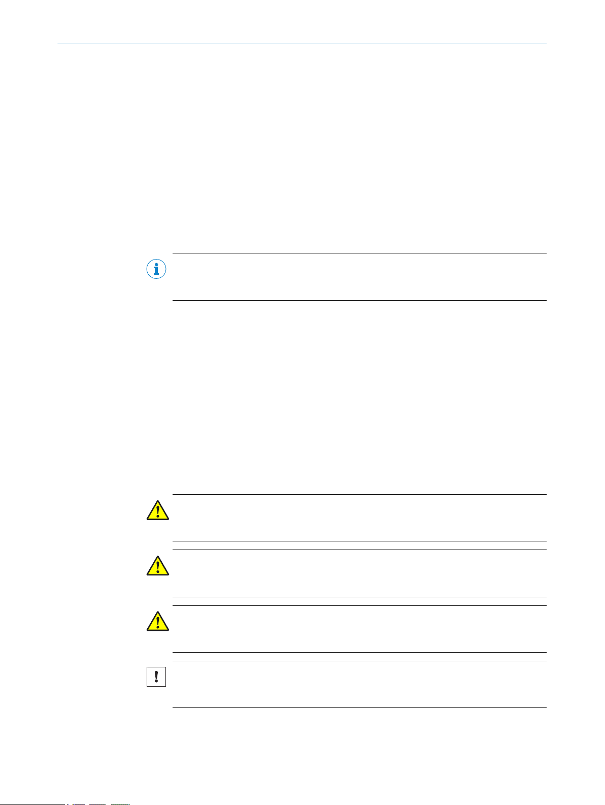
The TriSpector1000 uses laser triangulation on objects to produce 3D images. Embed‐
ded 3D image analysis tools are applied to the 3D images. The results are sent to a
control system via external interfaces.
Laser triangulation means that the object is illuminated with a laser from one direction,
and the camera acquires an image of the laser line from another direction. Each
acquired image contains a height profile, which corresponds to a cross-section of the
object. By making a scan, which means collecting height profiles across the object
while it moves, a complete 3D image can be acquired.
3.2
Figure 1: Laser triangulation principle
1
2
Figure 2: Height profile Figure 3: 3D image
Scope of delivery
The delivery of the device includes the following components:
■
TriSpector1000 series sensor
■
Printed quickstart in English and German
■
Printed safety notes
Accessories
Accessories, such as brackets and connecting cables, are only supplied if ordered sep‐
arately.
Field of view
Laser
10
O PE R AT I NG IN S TR U CT I ON S | TriSpector1000 8021808/12ID/2019-01 | SICK
Subject to change without notice

3.3 System requirements
For adequate SOPAS ET performance, use a PC with Intel Core I5 540M (2.53 GHz, 4
GB RAM) or better, and a screen resolution of at least 1024x768.
Graphics card: Intel® HD Graphics video card (or NVIDIA® NVS 3100M 512MB
GDDR3), or better. Make sure to use the latest graphic card drivers.
Ethernet connection is required, 100 Mbit/s or better. 1 Gbit/s or faster is recom‐
mended for best performance during configuration of the device via SOPAS ET.
Operating systems: Windows 7 or Windows 10 (64 bit is recommended).
SOPAS ET version: 2018.2 or higher
Hard drive: Minimum 550 MB.
Supported web browsers: Google Chrome (recommended due to advanced support of
WebGL and WebSockets) and Microsoft Edge.
SD memory card (optional): SICK microSD memory card (part no 4051366 or
4077575).
A mouse with at least three buttons (or a scroll wheel) is recommended.
3.4 TriSpector1000 variants
PRODUCT DESCRIPTION 3
TriSpector1000 is available with three different field of view (FoV) sizes and two differ‐
ent window materials. PMMA is a plastic material used as an alternative material to
glass in food processing environments.
Table 1: TriSpector1008 (Small FoV)
Window material No.
Glass 1075604
PMMA 1060426
Table 2: TriSpector1030 (Medium FoV)
Window material No.
Glass 1072923
PMMA 1060427
Table 3: TriSpector1060 (Large FoV)
Window material No.
Glass 1075605
PMMA 1060428
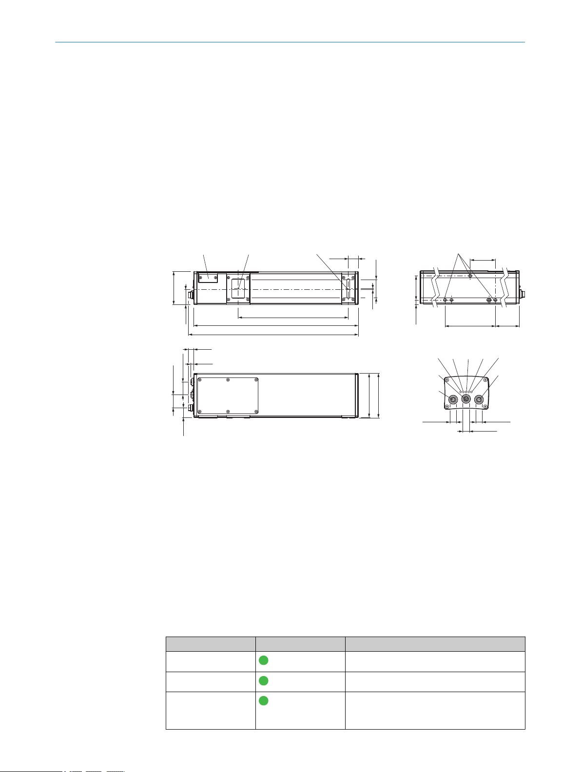
3.5 Dimensional drawings
See chapter 3.5.1, chapter 3.5.2 and chapter 3.5.3 for dimensional drawings for all
three TriSpector1000 variants. The dimensional drawings can also be downloaded as
CAD files from the TriSpector1000 device page at www.sick.com/TriSpector1000.
8021808/12ID/2019-01 | SICK O PE R AT I NG IN S TR U CT I ON S | TriSpector1000
Subject to change without notice
11
61.9 (1.26)
27.9
(1.10)
2
(0.08)
34
(1.34)
38
(1.50)
18.5
(0.73)
136 (5.35)
145.9 (5.74)
9.9
(0.39)
5.6
(0.22)
24 (0.94)
24 (0.94)
18
82 (3.23)
83.3 (3.28)
45
(1.77)
7.4
(0.29)
47
(1.85)
94 (3.70)
21
(0.83)
á ß à
4 5 6 7 8
9
32
1
M12 x 1
M12 x 1
M12 x 1
1
2
4
á ß à
5 6 7 8
9
3
61.9 (2.44)
27.9
(1.10)
114.5 (4.51)
217 (8.54)
226.9 (8.93)
18.5
(0.72)
2
(0.08)
34
(1.34)
M12 x 1
M12 x 1
M12 x 1
45
(1.77)
7.4
(0.29)
61.5 (2.42)94 (3.70)
9.9
(0.39)
5.6
(0.22)
83.3 (3.28)
47 (1.85)
3 PRODUCT DESCRIPTION
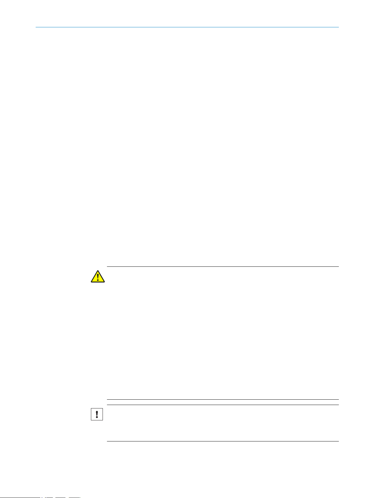
3.5.1 TriSpector1008
3.5.2 TriSpector1030
12
Connector Encoder (thread inside)
1
Connector Gigabit Ethernet (Gig E)
2
Connector Power I/O (thread outside)
3
LED: On
4
LED: State
5
LED: Link/Data
6
LED: Result
7
LED: Laser
8
Fastening threads (M5x8.5 length)
9
Optical receiver (center)
ß
Optical sender (center)
à
SD-card
á
Subject to change without notice
O PE R AT I NG IN S TR U CT I ON S | TriSpector1000 8021808/12ID/2019-01 | SICK
1
61.9 (1.26)
27.9
(1.10)
205.5 (8.09)
307 (12.09)
316.9 (12.48)
2
(0.08)
34
(1.34)
18.5
(0.73)
45
(1.77)
7.4
(0.29)
47
(1.85)
94 (3.70)
106.5
(4.19)
9.9
(0.39)
5.6
(0.22)
24 (0.94)
24 (0.94)
18
(0.71)
82 (3.23)
83.3 (3.28)
á ß à
1
2
4 5 6 7 8
3
9
M12 x 1
M12 x 1
M12 x 1
2
3
4
5
6
7
8
9
ß
à
á
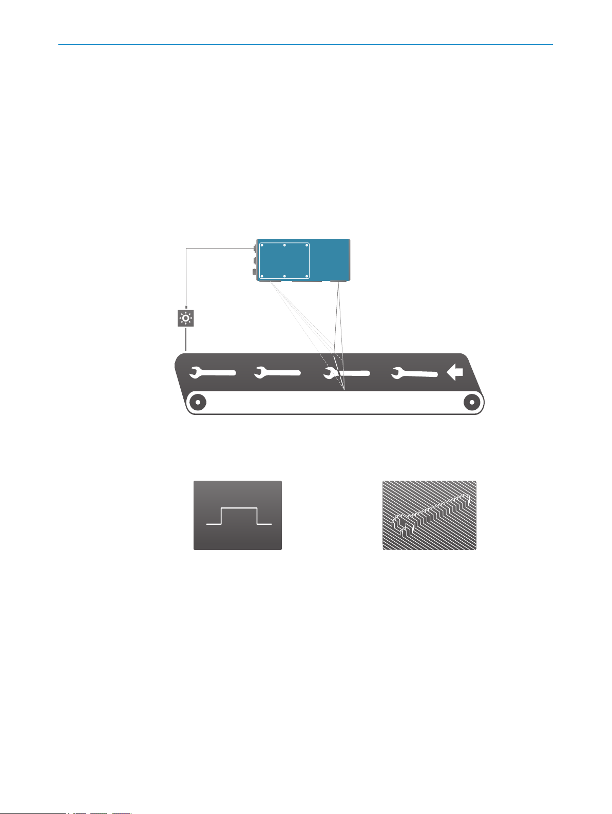
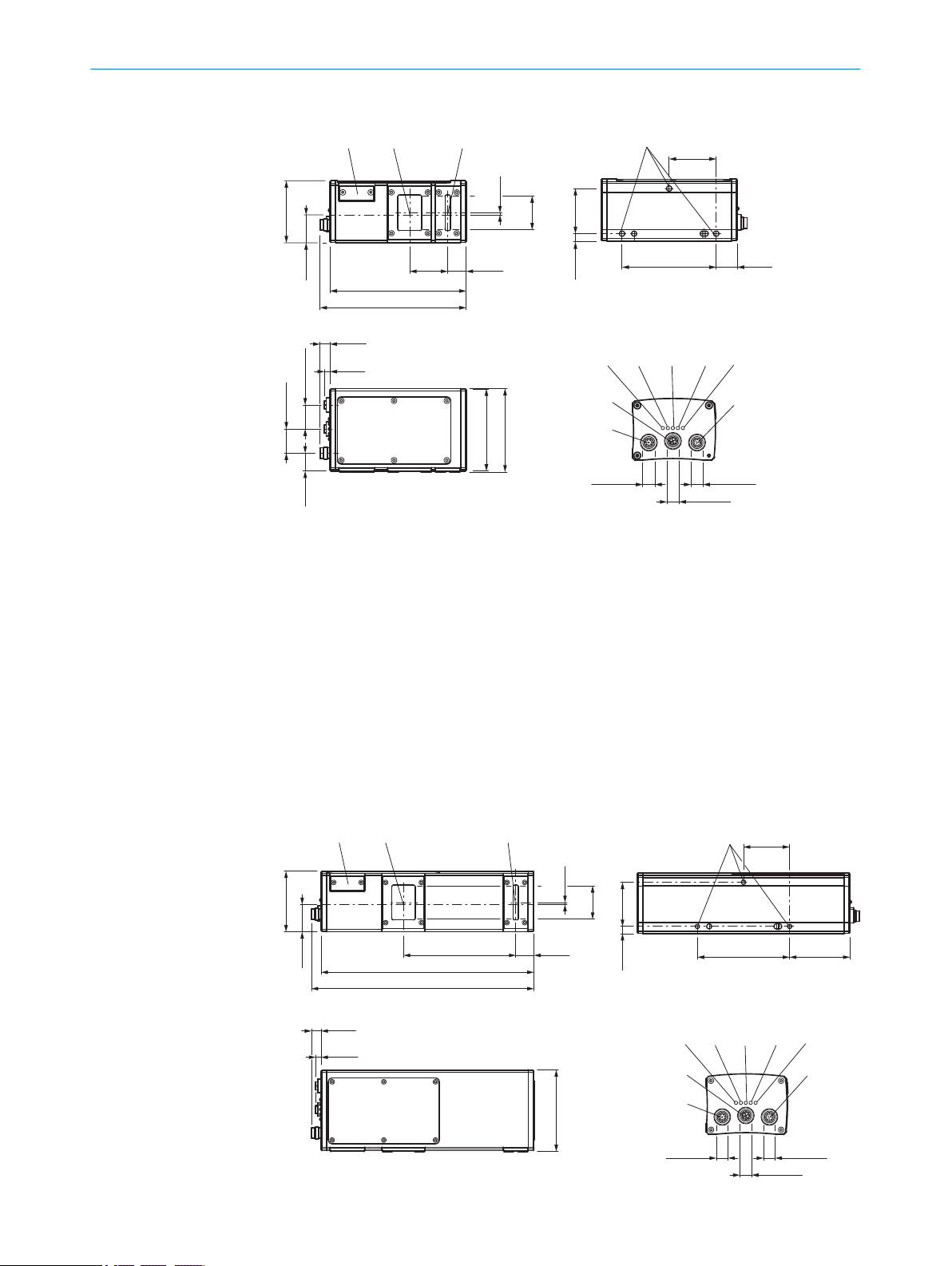
3.5.3 TriSpector1060
PRODUCT DESCRIPTION 3
Connector Encoder (thread inside)
Connector Gigabit Ethernet (Gig E)
Connector Power I/O (thread outside)
LED: On
LED: State
LED: Link/Data
LED: Result
LED: Laser
Fastening threads (M5x8.5 length)
Optical receiver (center)
Optical sender (center)
SD-card
3.6 LED indicators
8021808/12ID/2019-01 | SICK O PE R AT I NG IN S TR U CT I ON S | TriSpector1000
Subject to change without notice
Connector Encoder (thread inside)
1
Connector Gigabit Ethernet (Gig E)
2
Connector Power I/O (thread outside)
3
LED: On
4
LED: State
5
LED: Link/Data
6
LED: Result
7
LED: Laser
8
Fastening threads (M5x8.5 length)
9
Optical receiver (center)
ß
Optical sender (center)
à
SD-card
á
Name Color Function
On
State
Link/Data
Green Power on
Green Ready for trig input and image acquisition
Green Gigabit Ethernet (Gig E)
Link: LED on
Activity: LED blink
13

3 PRODUCT DESCRIPTION
Name Color Function
Result
Laser
Green Overall result: Pass
Red Overall result: Fail
Blue Result not found
No light Result invalid or neutral
Green Laser on
14
O PE R AT I NG IN S TR U CT I ON S | TriSpector1000 8021808/12ID/2019-01 | SICK
Subject to change without notice

4 Transport and storage
4.1 Transport
For your own safety, please read and observe the following notes:
NOTICE
Damage to the product due to improper transport.
■
The device must be packaged for transport with protection against shock and
damp.
■
Recommendation: Use the original packaging as it provides the best protection.
■
Transport should be performed by trained specialist staff only.
■
The utmost care and attention is required at all times during unloading and trans‐
portation on company premises.
■
Note the symbols on the packaging.
■
Do not remove packaging until immediately before you start mounting.
TRANSPORT AND STORAGE 4
4.2
Transport inspection
4.3 Storage
Immediately upon receipt in Goods-in, check the delivery for completeness and for any
damage that may have occurred in transit. In the case of transit damage that is visible
externally, proceed as follows:
■
Do not accept the delivery or only do so conditionally.
■
Note the scope of damage on the transport documents or on the transport com‐
pany's delivery note.
■
File a complaint.
NOTE
Complaints regarding defects should be filed as soon as these are detected. Damage
claims are only valid before the applicable complaint deadlines.
Store the device under the following conditions:
■
Recommendation: Use the original packaging.
■
Do not store outdoors.
■
Store in a dry area that is protected from dust.
■
So that any residual damp can evaporate, do not package in airtight containers.
■
Do not expose to any aggressive substances.
■
Protect from sunlight.
■
Avoid mechanical shocks.
■
Storage temperature: see "Ambient data", page 61.
■
Relative humidity: see "Ambient data", page 61.
■
For storage periods of longer than 3 months, check the general condition of all
components and packaging on a regular basis.
8021808/12ID/2019-01 | SICK O PE R AT I NG IN S TR U CT I ON S | TriSpector1000
Subject to change without notice
15
5 MOUNTING
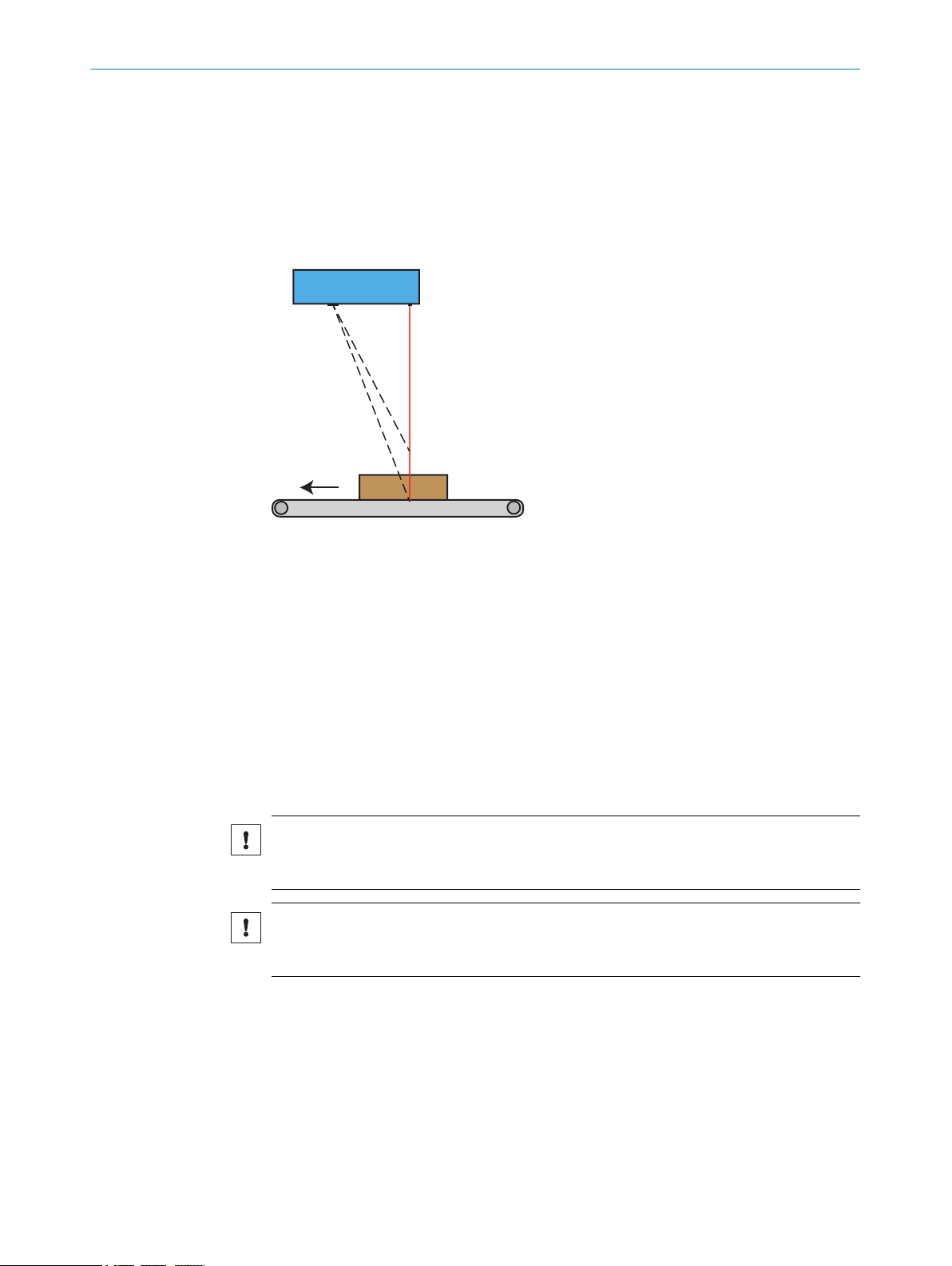
5 Mounting
5.1 Mounting instructions
Mount the TriSpector1000 in a position above the surface to be scanned. See "Field of
view diagrams", page 17 for field of view diagrams and mounting distances. The
default scan direction is shown in figure 4. If a scan is performed in the opposite direc‐
tion, the acquired image will be mirrored.
Figure 4: Mounting position
For optimal performance:
■
Observe the ambient conditions for the operation of the TriSpector1000 (for exam‐
ple, ambient temperature and ground potential). See "Technical data", page 61
for specifications.
■
Ensure adequate heat transfer from the device, for example, via the mounting
bracket to the mounting base, or by means of convection.
■
Use a stable bracket with sufficient load bearing capacity and suitable dimensions
for the TriSpector1000.
■
Minimize shock and vibration.
■
Ensure a clear view of the objects to be detected.
5.1.1 Mounting a microSD memory card
NOTICE
If the TriSpector1000 is powered on, click the Eject button in the SD Card section under
the Interfaces workflow step before removing the microSD memory card.
NOTICE
The screws for the microSD memory card lid must be tightened with a torque of 0.3 Nm
to keep the IP65 classification.
16
Follow the steps below to insert or remove a microSD memory card to or from the
TriSpector1000. The microSD memory card slot is located next to the inspection win‐
dow.
1. Release the two screws to remove the lid.
2. Insert or remove the microSD memory card.
3. Re-mount the lid and tighten the screws with a torque of 0.3 Nm.
For a specification of supported microSD memory cards, see "System requirements",
page 11.
O PE R AT I NG IN S TR U CT I ON S | TriSpector1000 8021808/12ID/2019-01 | SICK
Subject to change without notice
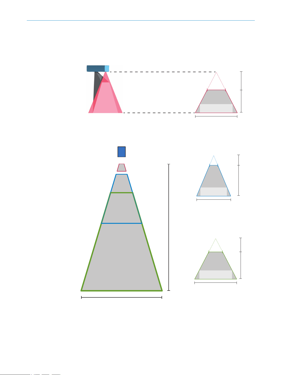
5.2 Field of view diagrams
56
(2.20)
60
(2.36)
75
(2.95)
H
W
65 x 15
(2.56 x 0.59)
40
(1.57)
TriSpector1008
291
(11.46)
800
(31.50)
660
(25.98)
H
W
540 x 200
(21.26 x 7.87)
180
(7.09)
TriSpector1060
141
(5.55)
400
(15.75)
330
(12.99)
H
W
270 x 100
(10.63 x 3.94)
90
(3.54)
TriSpector1030
Y
X
TriSpector1000
Y = Max. height range
X = Width at max.
working distance
Typical field of view
TriSpector1008
TriSpector1030
TriSpector1060
The maximum guaranteed image acquisition area in mm (inch) for each TriSpector1000
variant is shown in figure 5. The brighter areas represent typical image acquisition
areas.
MOUNTING
5
Figure 5: Field of view diagrams
8021808/12ID/2019-01 | SICK O PE R AT I NG IN S TR U CT I ON S | TriSpector1000
Subject to change without notice
17

ELECTRICAL INSTALLATION
6
6 Electrical installation
6.1 Prerequisites for the safe operation of the device in a system
WARNING
Risk of injury and damage due to electrical current!
Incorrect grounding of the device can result in equipotential bonding currents between
the device and other grounded devices in the system. This can lead to the following
dangers and faults:
Hazardous voltages are applied to the metal housings.
•
Devices will malfunction or sustain irrepairable damage.
•
Cable shieldings are damaged by overheating and cause cable fires.
•
Remedial measures:
Only qualified electricians should be permitted to carry out work on the electrical
•
system.
Install the grounding for the sensor and the system in accordance with national
•
and regional regulations.
Ensure that the ground potential is the same at all grounding points.
•
If the cable insulation is damaged, disconnect the voltage supply immediately and
•
have the damage repaired.
Observe the following safety measures:
■
Only skilled electricians with appropriate training and qualifications are permitted
to perform electrical installation.
■
Standard safety requirements must be met when working in electrical systems.
■
Electrical connections between the TriSpector1000 and other devices may only be
made or disconnected when there is no power to the system. Otherwise, the
devices may be damaged.
■
Where connecting cables with one end open are concerned, make sure that bare
wire ends do not touch each other (risk of short circuit when the supply voltage is
switched on). Wires must be appropriately insulated from each other.
■
Wire cross sections of the supply cable from the customer's power system should
be designed and protected in accordance with the applicable standards.
■
If the supply voltage for the TriSpector1000 is not supplied via the CDB650-204
connection module, the TriSpector1000 must be protected by a separate slowblow fuse with a max. rating of 2.0 A. This fuse must be located at the start of the
supply circuit.
■
All circuits connected to the TriSpector1000 must be designed as SELV circuits
(SELV = Safety Extra Low Voltage).
18
O PE R AT I NG IN S TR U CT I ON S | TriSpector1000 8021808/12ID/2019-01 | SICK
Subject to change without notice
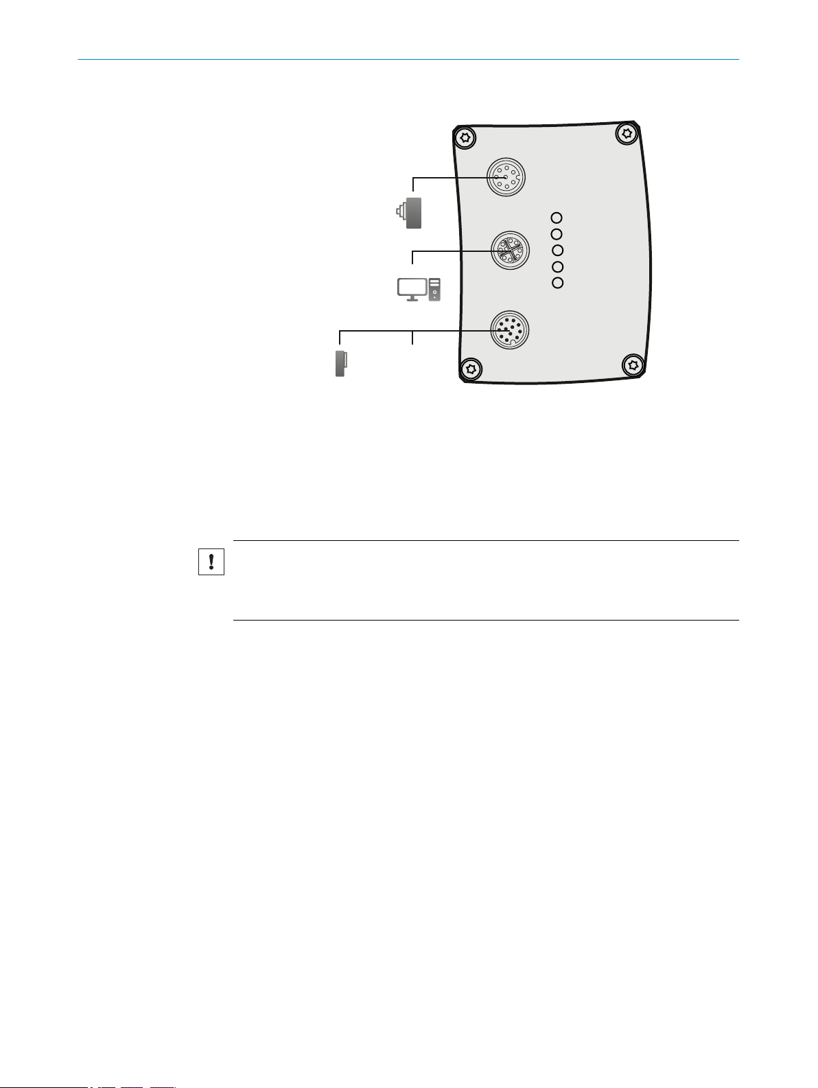
6.2 Connection diagram
Power
I/O
Gig
E
Encoder
On
State
Link/Data
Result
Laser
PC
24 V DC
Encoder
Photoelectric
switch
1
2
3
4
Figure 6: Connection diagram
Encoder
1
PC/Network
2
Photoelectric switch
3
24 V DC, voltage supply
4
ELECTRICAL INSTALLATION 6
6.3 Encoder
NOTICE
It is strongly recommended to use an encoder for measuring applications, such as
shape measuring and volume measuring. If no encoder is used, analysis results may be
inaccurate due to object traversing speed variations.
The encoder must fulfill the following requirements:
■
The encoder must be an incremental encoder.
■
The encoder must have a RS-422/TTL interface. In the case of strong magnetic
fields in proximity to the TriSpector1000 a recommended encoder (no. 1068997)
must be used to ensure optimal performance.
■
The connection requires two encoder channels (A/A¯ and B/B¯) to keep track of
movement and direction.
8021808/12ID/2019-01 | SICK O PE R AT I NG IN S TR U CT I ON S | TriSpector1000
Subject to change without notice
19

4
3
6
5
7
8
1
2
4
3
6
5
7
8
1
2
6 ELECTRICAL INSTALLATION
6.4 Pin assignment
Encoder I/O
Figure 7: M12 female connector, 8-pin A-coded
Pin Signal
1 A/ - RS-422 inverted input
2 A - RS-422 non-inverted input
3 B/ - RS-422 inverted input
4 B - RS-422 non-inverted input
5 (Not connected)
6 (Not connected)
7 GND (Power / Signal)
8 24 V Voltage supply output
Gigabit Ethernet
Figure 8: M12 female connector, 8-pin X-coded
Pin Signal
1 GETH_L1+
2 GETH_L1-
3 GETH_L2+
4 GETH_L3+
5 GETH_L3-
6 GETH_L2-
7 GETH_L4+
8 GETH_L4-
20
O PE R AT I NG IN S TR U CT I ON S | TriSpector1000 8021808/12ID/2019-01 | SICK
Subject to change without notice

11
5
7
2
1
10
12
3
4
6
8
9
ELECTRICAL INSTALLATION 6
Power I/O
Figure 9: M12 male connector, 12-pin A-coded
Pin Signal
1 24 V Voltage supply input
2 Ground (Power / Signal)
3 24 V - I/O 3, Trigger in
4 24 V - I/O 4, Configurable
5 24 V - I/O 2, Input
6 24 V - I/O 5, Configurable
7 24 V - I/O 6, Configurable
8 24 V - I/O 1, Input
9 24 V - I/O 7, Configurable
10 Reserved
11 RS-232 Rx
12 RS-232 Tx
8021808/12ID/2019-01 | SICK O PE R AT I NG IN S TR U CT I ON S | TriSpector1000
Subject to change without notice
21
7 OPERATION
7 Operation
7.1 Commissioning
7.1.1 Installing SOPAS
The SOPAS Engineering Tool (ET) software for PC is used to connect and configure SICK
devices.
To install SOPAS ET:
1. Download the latest version of SOPAS ET from www.sick.com. Version 2018.2 or
higher is required.
2. Run the downloaded installation file.
3. Follow the instructions on the screen.
7.1.2 Connecting the hardware
1. Connect the Ethernet cable between the TriSpector1000 and the PC.
2. Connect the TriSpector1000 Power I/O cable to a 24 V DC power supply:
Brown: +24 V DC, Pin 1
Blue: Ground, Pin 2
3. Connect the encoder cable between the TriSpector1000 and the encoder (if
applicable).
7.1.3 Connecting the TriSpector1000 to SOPAS ET
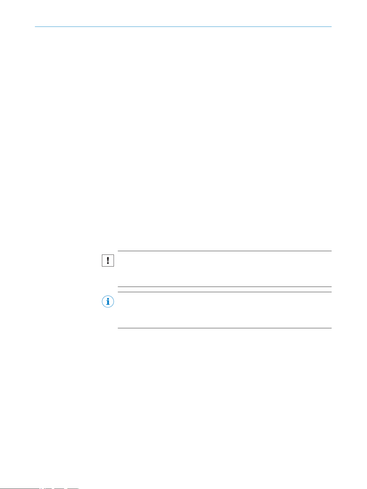
1. Start SOPAS ET.
✓
The SOPAS ET main window opens. The main window is split into two panes, the
project pane to the left and the device pane to the right.
NOTICE
At the first use, the TriSpector1000 requires a SICK Device Driver (SDD). When
adding the device to a project, a prompt will appear with instructions on how to
install the driver. When prompted for SDD installation source, select Device upload.
NOTE
In the device list, the TriSpector1000 device is available on port 2111 and 2112.
Do not use port 2111. This port is used for debugging and may decrease the oper‐
ation speed.
2. To add the TriSpector1000 to the SOPAS project, select the device on port 2112 in
the device pane and click Add.
✓
A product icon appears in the project pane.
22
O PE R AT I NG IN S TR U CT I ON S | TriSpector1000 8021808/12ID/2019-01 | SICK
Subject to change without notice
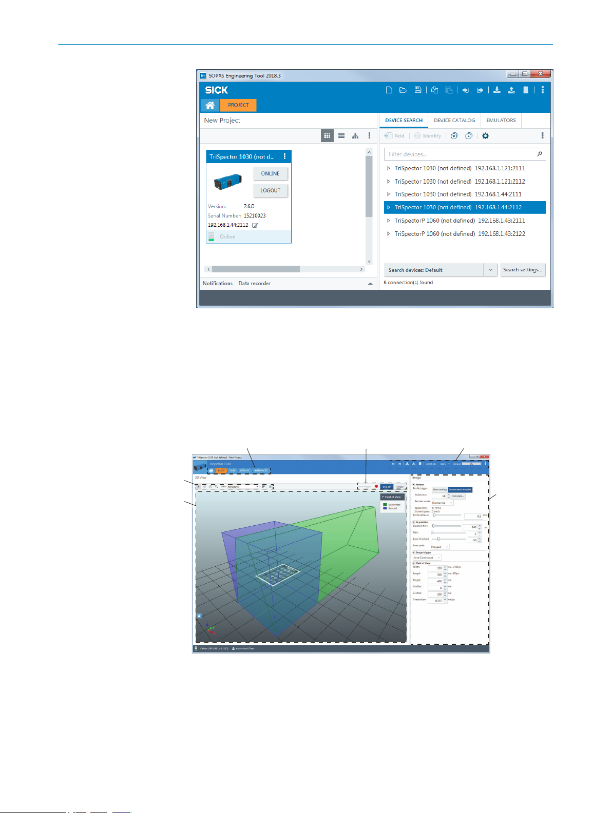
Figure 10: SOPAS ET main window
2
4 5
1
3
6
OPERATION 7
3. Double-click the product icon to open the SOPAS ET device window and start the
4. If there are IP address connection issues, click the Edit icon in the device tile to
7.2
Description of the user interface
The TriSpector1000 is configured through the SOPAS ET device window.
configuration.
make adjustments. The default IP address is 192.168.0.30.
Figure 11: SOPAS ET device window
Image area
1
Image handling controls and view options
2
Parameter pane
3
Workflow steps
4
Controls for image view, image recording (red), and Force trigger
5
SOPAS ET functions panel
6
8021808/12ID/2019-01 | SICK O PE R AT I NG IN S TR U CT I ON S | TriSpector1000
Subject to change without notice
23

7 OPERATION
7.2.1 Menus
Three menus are available in the SOPAS ET functions panel: the Device menu, the Para‐
meter menu and the Functions menu.
Device menu
Go online Establish a connection between SOPAS ET and the TriSpec‐
tor1000.
Go offline Switch the connection mode to offline. In this mode, parameter
values cannot be written to the device and measurements cannot
be monitored. The connection information in SOPAS ET remains
intact.
Switch to physical device Switch from the emulator to the TriSpector1000 and import the
configuration. This option is only enabled when running the emula‐
tor. For details, see "Copying a configuration from the emulator",
page 56.
Switch to simulated device Switch from the TriSpector1000 to the emulator. For details, see
"Starting the emulator", page 54.
Login... Log in to the device at a certain user level. When a device is added
to a SOPAS project, the user level is automatically set to Authorized
Client, which is the required level for saving parameter values to
the device. The current user level is shown below the image area.
Logout Cancel the login. Once the user has logged out, parameters
secured by the user level can no longer be changed.
Import... Import a saved device configuration from a PC. For details,
see "Exporting and importing data", page 56.
Export... Export the current device configuration to a PC. For details,
see "Exporting and importing data", page 56.
Create PDF Create a PDF which includes device parameters and their values.
Properties Open the Device Settings window.
Close Close the SOPAS ET device window.
Parameter menu
Write to device Write the configuration saved in the SOPAS project to the device.
Read from device Read the configuration from the device and saves it in the SOPAS
Save permanent Save the configuration in the device flash memory and to the
Functions menu
Load factory defaults Reset all SOPAS ET parameters including IP address.
Load application defaults Reset all SOPAS ET parameters except IP address.
Save image to file Save the current image to disk.
Image recording Save multiple images to disk. For details, see "Recording images",
7.2.2 Image handling controls
Use the image handling controls to manipulate regions and perspective when viewing
images. As an alternative to the buttons, you can use a mouse with a scroll wheel, as
described below.
project.
microSD memory card (when applicable).
page 32.
24
O PE R AT I NG IN S TR U CT I ON S | TriSpector1000 8021808/12ID/2019-01 | SICK
Subject to change without notice
Z
XY
OPERATION 7
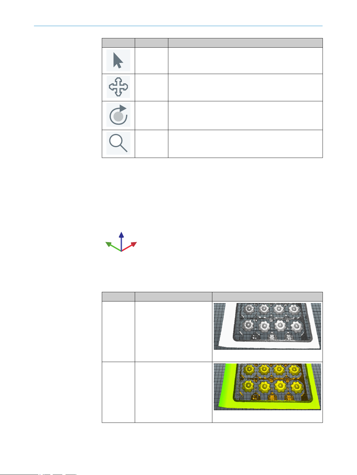
Button Name Description
Select Click and drag to change the size and position of the image.
Shortcut command: Ctrl+Q.
Move Click and drag to move the image.
Shortcut command: Ctrl+W.
Shift+ press and hold the mouse scroll wheel.
Rotate Click and drag to rotate the image.
Shortcut command: Ctrl+E.
Press and hold the mouse scroll wheel.
Zoom Click and drag upwards to zoom in and downwards to zoom out.
Shortcut command: Ctrl+R.
Rotate the mouse scroll wheel.
3D navigation control
Use the 3D navigation control in the lower left corner of the image viewer to switch
between different viewing angles:
•
•
•
Figure 12: 3D navigation control
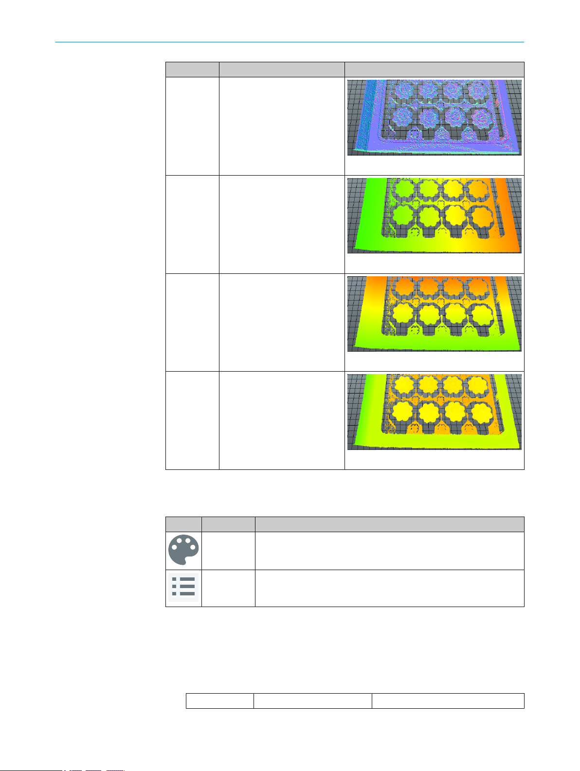
7.2.3 Image view modes
The following view modes are available:
View mode Description Example
Reflectance Color is proportional to the
Reflectance
(Hybrid)
Click an arrowhead (X, Y or Z) to view a 2D projection of the object.
Click the same arrowhead twice to flip the 2D projection (for example, to switch
between the top and bottom view for the Z-axis).
Press Home to restore the original viewing position.
reflectance values along the
laser line.
Suitable to show the surface
details of an object, such as a
print.
Figure 13: Reflectance view mode
Color is proportional to depth (zcoordinate), color brightness is
proportional to the laser
reflectance.
Suitable to show large variations
in depth together with surface
details.
Figure 14: Reflectance (Hybrid) view mode
8021808/12ID/2019-01 | SICK O PE R AT I NG IN S TR U CT I ON S | TriSpector1000
Subject to change without notice
25
7 OPERATION
View mode Description Example
Normals Color is proportional to the ori‐
entation of the surface normal
vector.
Suitable to show small varia‐
tions in depth, such as surface
structures.
Figure 15: Normals view mode
X Color is proportional to x-coordi‐
nate.
Figure 16: X view mode
Y Color is proportional to y-coordi‐
nate.
Z Color is proportional to depth (z-
7.2.4 Image view options
The Color and Options buttons contain image view options.
Button Name Description
b
Figure 17: Y view mode
coordinate).
Suitable to show large variations
in depth.
Figure 18: Z view mode
Color View image in color or grayscale
Options Contains options for Color Range, Grid, Surface and Points, as described
below.
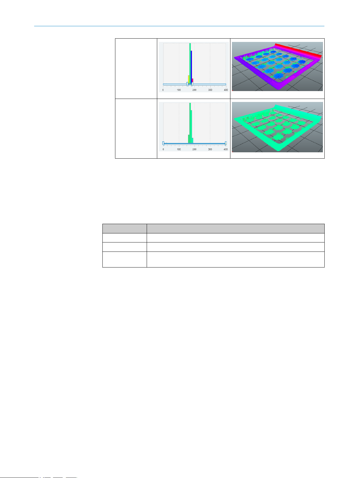
Click Color Range to adjust the color interval of the displayed image. This option is
only applicable for the X, Y, Z and Reflectance view modes.
The available color spectrum covers the whole range between the minimum and
the maximum value. Make the interval smaller if the scanned object is small, or to
view a part of the object in detail. This means that the whole color spectrum is
spread over a smaller interval, and it will be easier to see small variations in
depth.
Applied color range Resulting image
26
O PE R AT I NG IN S TR U CT I ON S | TriSpector1000 8021808/12ID/2019-01 | SICK
Subject to change without notice
b
b
7.2.5 Image view controls
OPERATION 7
Narrow color
range
Broad color
range
Click Grid to show or hide the grid at the bottom of the field of view.
Click Surface to view the image as a continuous surface, or Points to view the image
as a point cloud. The point size can be adjusted by the user.
The image view controls are used to switch between the Live 3D image, the Job image,
and the Sensor view. Different image view controls are available in different workflow
steps.
Image view Description
Job Show the job image stored with the Save job image button.
Live 3D Display the latest scanned image.
Sensor Display the object as perceived by the image sensor. Use this view to adjust
image acquisition settings.
7.3 Handling jobs and configurations
A set of image, task and result settings is referred to as a job in SOPAS ET, while a set
of jobs and interface settings is referred to as a configuration.
Use SOPAS ET to manage jobs and to save the resulting configuration. A maximum of
32 jobs can be included in a configuration. Up to 32 tools can be applied to each job,
but only one Shape tool.
Loading a configuration
When powering on the TriSpector1000, the configuration stored on the microSD mem‐
ory card is automatically loaded into the device's working memory. If no microSD mem‐
ory card is inserted, or if there is no configuration stored on the microSD memory card,
the configuration is loaded from the device's flash memory to the working memory.
Managing jobs
Click the Select job menu in the SOPAS ET functions panel to manage and select jobs.
At the first use of the TriSpector1000, a new job ('Job 0') is created in the device's work‐
ing memory. When an existing configuration is loaded into the device's working memory,
the job that was active when the configuration was saved is automatically activated.
8021808/12ID/2019-01 | SICK O PE R AT I NG IN S TR U CT I ON S | TriSpector1000
Subject to change without notice
27

7 OPERATION
Saving a configuration
NOTICE
If a configuration is not saved before disconnecting the power to the device, all settings
will be lost.
Select Save permanent from the Parameter menu in the SOPAS ET functions panel to save
a configuration from the device's working memory to the flash memory. If the device
has a microSD memory card inserted, the configuration is saved to both the flash mem‐
ory and the microSD memory card.
Cloning a device using a microSD memory card
Follow the steps below to clone a device, which means copying the configuration and IP
address from one device to another. The instruction requires that the first device has a
microSD card inserted and is connected to SOPAS ET.
1. In SOPAS ET, select Save permanent from the Parameter menu to save the current
configuration to the microSD memory card.
2. Move the microSD memory card from the first to the second device.
3. Power on the second device.
✓
The configuration on the microSD memory card is loaded into the working memory
of the second device.
4. Select Save permanent from the Parameter menu in the SOPAS ET functions panel to
save the configuration to the device's flash memory.
7.4 Workflow steps
To configure the TriSpector1000, click the workflow steps in the user interface (see
figure 19). It is possible to change workflow step at any time during the configuration.
Figure 19: Workflow steps
Image
The Image workflow step is used to set up image acquisition for good image quality. Two
different views are available: Live 3D and Sensor. See "Image workflow step", page 29
for more information.
Task
The Task workflow step contains tools for image analysis. Two different views are avail‐
able: Live 3D and Job. The Job image is the reference image where the tools are applied
and the tool configuration is done. See "Task workflow step", page 32 for more infor‐
mation.
Results
The Results workflow step contains settings for result processing and output handling.
Note that a bold red underscore in the input fields indicates syntax error. See "Results
workflow step", page 43 for more information.
28
Interfaces
The Interfaces workflow step contains settings for connections to external interfaces.
See"Interfaces workflow step", page 50 for more information.
O PE R AT I NG IN S TR U CT I ON S | TriSpector1000 8021808/12ID/2019-01 | SICK
Subject to change without notice
7.5 Image workflow step
Scan
No scan
Forward scanning direction
Motion
Position Up
Direction Up
Scan
No scan
Scan
7.5.1 Scanning an object
The TriSpector1000 builds the image by acquiring a number of laser line profiles of a
moving object. Use an encoder if motion is not constant.
1. In the Motion section, select Profile trigger:Free running or Incremental encoder and
specify the parameters accordingly. If applicable, click Calculate for assistance with
encoder calculation. See "Encoder modes", page 29 for descriptions of the
encoder modes.
2. Move the object under the TriSpector1000 laser line to make a scan.
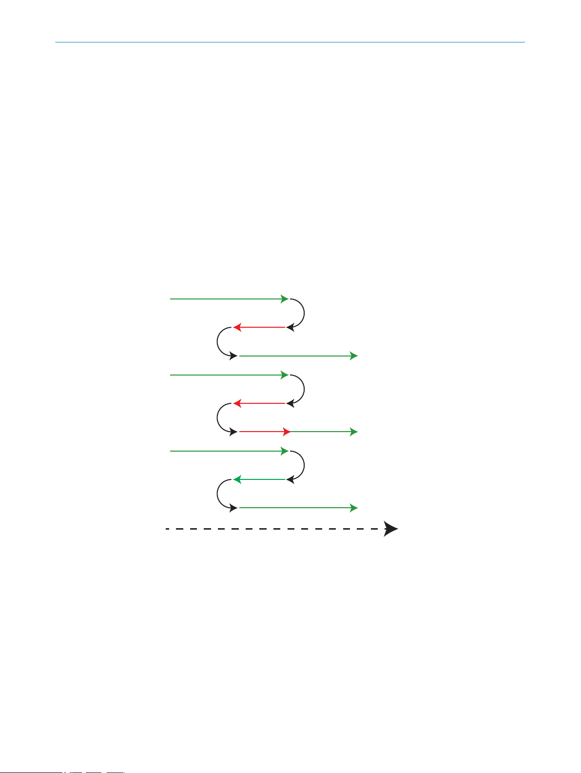
7.5.1.1 Encoder modes
The TriSpector1000 has a two directional (up/down) encoder pulse counter. The for‐
ward (up) scanning direction is defined as clockwise encoder shaft movement, as seen
from the tip of the shaft. See the Current speed parameter in the Image workflow step for
traversing speed. There are five encoder pulse counter-modes: direction up/down, posi‐
tion up/down and motion.
OPERATION
7
Figure 20: Encoder pulse counter-modes
8021808/12ID/2019-01 | SICK O PE R AT I NG IN S TR U CT I ON S | TriSpector1000
Subject to change without notice
29
7 OPERATION
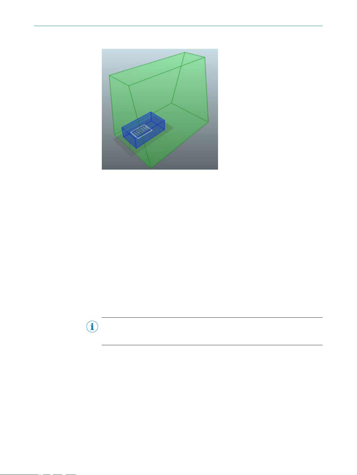
7.5.2 Setting the field of view
Figure 21: Field of view
The field of view consists of two regions displayed in the image area:
■
Guaranteed field of view (green region): The field of view where image acquisition
is possible. The guaranteed field of view for the TriSpector1000 consists of 2500
profiles, and the region length is determined by the Profile distance parameter.
■
Selected field of view (blue region): The region in which the camera acquires range
data for image analysis. The Width and Height of this region are set to maximum by
default. The default Length depends on the device model (120-480 mm).
Adjust the field of view to optimize performance:
■
Edit the Profile distance parameter in the Motion section in the parameter pane to
change the length of the guaranteed field of view. A smaller profile distance allows
a higher scan density but reduces the region length.
■
Use the value boxes in the Field of view section in the parameter pane to resize the
selected field of view. A smaller region allows faster processing and higher profile
frequency rate.
■
Make the pixels in the selected field of view more square by setting the X-resolution
parameter to a value similar to the Profile distance parameter.
NOTE
If the X-resolution and the profile distance differ more than a factor 3, some tools may
not work properly.
7.5.3 Adjusting the image settings
To adjust the image settings to get a good 3D image:
1. Click the Sensor button located above the image area to see the laser profile which
can be used as reference when adjusting the exposure time and gain. See "Laser
line exposure time", page 31 for examples.
2. Click the Live 3D button and perform a scan.
3. In the Acquisition section, adjust the Exposure time and Gain until the 3D live view
looks good.
Try to keep the gain low, and instead increase the exposure time. This will reduce
noise in the image.
4. Adjust the Laser threshold parameter to determine which image sensor intensity val‐
ues to include when locating laser peaks. A high threshold value results in less
30
O PE R AT I NG IN S TR U CT I ON S | TriSpector1000 8021808/12ID/2019-01 | SICK
Subject to change without notice
OPERATION 7
noise in the range image, while a low threshold value makes it possible to detect
weak laser peaks.
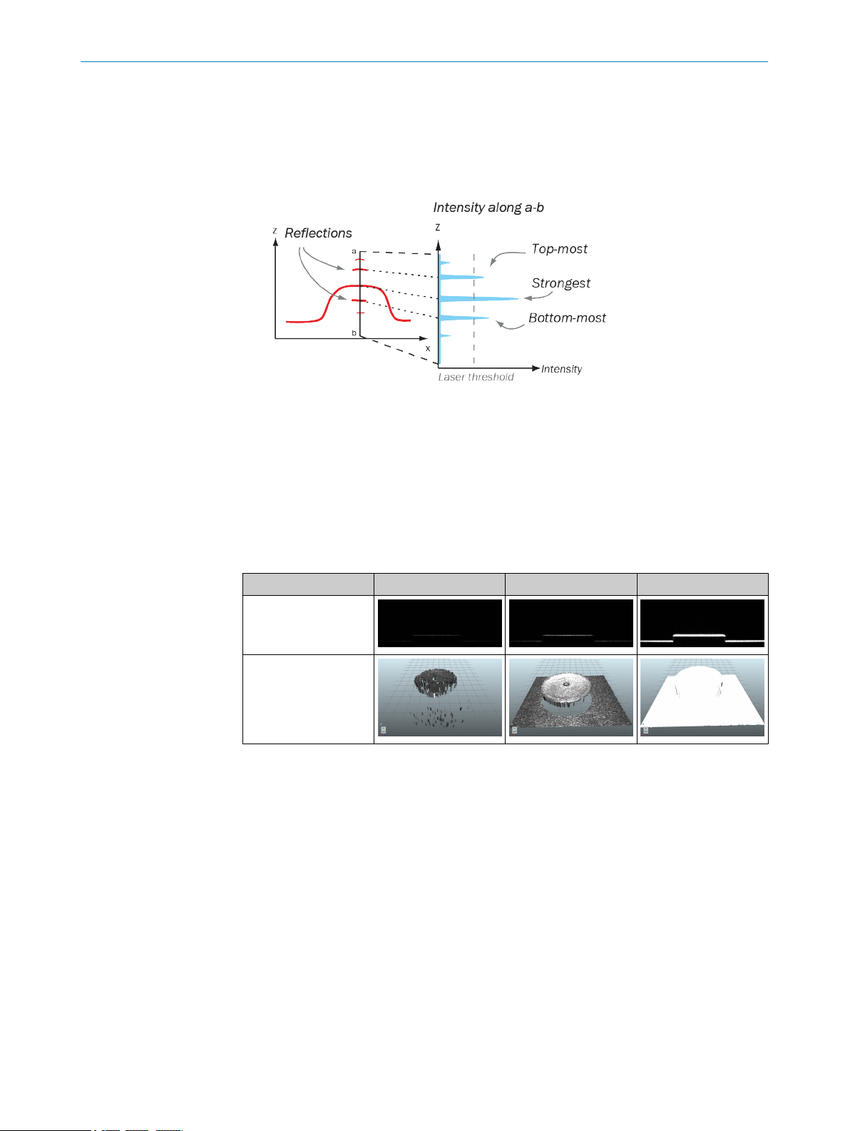
5. Select laser line acquisition criteria in the Laser peak list:
Strongest locates the point with the highest intensity.
°
Top Most and Bottom Most locate the highest or lowest point with an intensity
°
higher than the value set by the Laser threshold parameter. See figure 22.
Figure 22: Laser line acquisition criteria.
6. Repeat the procedure if necessary.
7.5.3.1 Laser line exposure time
The optimal exposure time yields a gray line in the 2D sensor image representation. A
slightly brighter line is preferable to a slightly darker line. A solid white laser line indi‐
cates a too long exposure time and will result in an overexposed image. See the images
below for examples of 2D sensor images and Live 3D images depicting short exposure
time, normal exposure time, and long exposure time (from left to right).
View Short exposure time Normal exposure time Long exposure time
Sensor view
Live 3D view
7.5.4 Configuring the trigger settings
The Image Trigger section is used to determine when image acquisition starts.
Set the Image trigger parameter to None (Continuous) to acquire images continuously.
b
Select Object trigger to define a plane on a certain height. The image acquisition
b
starts when an object is above the specified plane.
Select Command Channel to trigger the image acquisition from the command chan‐
b
nel.
Set the parameter to Trigger on I/O 3 to trigger the TriSpector1000 by digital I/O via
b
a photoelectric switch or a PLC. The image acquisition can be delayed by time (ms)
or distance (mm) from the signal input.
The TriSpector1000 triggers on a rising edge. The trigger pulse must be at least 50
μs. The TriSpector1000 ignores succeeding pulses during image acquisition.
Click the Force trigger button above the image area to start an image acquisition. If
b
an acquisition is already ongoing, it will be interrupted and re-started.
8021808/12ID/2019-01 | SICK O PE R AT I NG IN S TR U CT I ON S | TriSpector1000
Subject to change without notice
31

7 OPERATION
7.5.5 Recording images
Use the Image recording button ( ) to save 3D images to disk. The saved images can be
used in the emulator to configure tools offline. See "Using the SOPAS ET emulator",
page 54 for information on how to use the emulator.
The saved images are Portable Network Graphics (.png) files which contain both range
data and reflectance data. Each file name includes the name of the active job, the
image number and the overall image decision.
To save images to disk:
1. Click the Image recording button.
✓
2. Select a destination folder.
3. Select the Max number of images checkbox to specify the maximum number of
4. Select the Reset image numbering checkbox to overwrite existing files in the destina‐
5. Click the Start button.
✓
6. Click the Image recording button stop the image recording. If the Max number of images
The Image recording settings window opens, and the Image recording button turns
black.
images to save.
tion folder.
The image recording starts. An image is saved each time a scan is made.
checkbox was selected, the recording will stop automatically when the specified
number of images have been saved.
7.6 Task workflow step
7.6.1 Using the tools
1. After the image configuration has been done in the Image workflow step, select
the Task workflow step.
✓
The image is shown in the Live 3D view.
2. Click the Save Job Image button.
✓
The Tools buttons appear and the image view changes to Job.
3. Click on a tool button to apply the tool to the image. You can apply multiple tools to
the image, but only one Shape tool.
4. Click the eye symbol ( ) in the parameter pane to toggle the visual representa‐
tion on or off. If applicable, click one more time to also show the tool's region of
interest.
Selecting a tool in the parameter pane will always show the visual representation
for the tool.
The Job image view shows the saved job image. Tools can only be applied in this view.
The Live 3D view shows the latest scanned image.
For an example of how to use tools for image analysis, see "Application example: Count‐
ing chocolates", page 41.
32
O PE R AT I NG IN S TR U CT I ON S | TriSpector1000 8021808/12ID/2019-01 | SICK
Subject to change without notice

7.6.2 Setting the region of interest
Figure 23: The region of interest (yellow)
The region of interest is the region that a tool is applied to. The region of interest is set
for each tool and is displayed as a yellow box in the image area.
OPERATION 7
To set the region of interest for a tool:
1. Select a tool in the parameter pane.
2. Click the Select button in the image handling controls panel.
3. In the 3D navigation control in the lower left corner of the image area, click the
green arrowhead for a FRONT view.
4. Use the Height range slider in the Settings section in the parameter pane to adjust
the height of the 3D region, so that it covers only the region of interest. This is
important to only include relevant data, and to reduce the processing time.
5. In the 3D navigation control, click the blue arrowhead for a TOP view.
6. Select the most applicable Region shape in the parameter pane.
7. Use the region of interest handles (figure 24) or the region of interest manipulator
(figure 25) in the image area to adjust the sides and position of the 3D region, so
that it covers only the region of interest.
8. If needed, select Masks in the parameter pane to apply a mask that excludes nonrelevant parts from the region.
Region of interest handles
Figure 24: Region of interest handles.
Hover over the region of interest to highlight its handles. Click and hold a handle to
move or scale the region of interest, according to figure 24.
8021808/12ID/2019-01 | SICK O PE R AT I NG IN S TR U CT I ON S | TriSpector1000
Subject to change without notice
33

y
x
y
x
7 OPERATION
7.6.3 Tool groups
Region of interest manipulator
Figure 25: Region of interest manipulator.
Click on the arrows in the image area to move, scale or rotate the region of interest,
according to figure 25.
The tools are divided into three groups:
Find tools Locate objects of different shapes, or features such as
edges and planes.
7.6.4 Shape tool
Inspect tools Inspect properties on located objects or fixed regions in
the image.
Measure tools Measure distance and angle between located objects or
features.
Each tool group includes the following tools:
Find tools Shape tool, Blob tool, Edge tool, Plane tool, Fix Plane tool,
Point tool, Peak tool
Inspect tools Area tool
Measure tools Angle tool, Distance tool
Shape The Shape tool locates a 3D shape in the image and reposi‐
tions other tools accordingly. Use the Shape tool when the
position or rotation of the object varies.
NOTE
If the X-resolution and the profile distance of the image differ more than a factor 3, the
Shape tool will not work properly. To adjust the values, see "Setting the field of view",
page 30.
Shape tool settings
Setting Description
Region shape Set the shape of the region of interest to rectangular or elliptical.
Height range Set upper and lower bounds of the region of interest on the Z-axis.
34
O PE R AT I NG IN S TR U CT I ON S | TriSpector1000 8021808/12ID/2019-01 | SICK
Subject to change without notice

y
x
OPERATION 7
Setting Description
Min. search score Minimum search score for Pass/Fail criteria. Lower search scores
than set value returns in a 'Not Found' result.
Min. edge threshold Only include shapes of greater height than the minimum thresh‐
old.
Robustness Set trade-off between speed and robustness. Low robustness will
result in fewer data points considered to find shape.
Rotation Maximum allowed shape rotation to search for. The greatest possi‐
ble value is ±180 degrees.
Masks Mask a part of the image to exclude it from the search.
Shape tool result output
Result Output
Decision OK/Not OK/Invalid/Neutral/Not found
Rotation Rotation in degrees.
Score Score value (0-100).
Tx, Ty, T
z
Translation (x, y, z) in mm.
7.6.5 Blob tool
Linking other tools to the Shape tool
If other tools are added after the Shape tool, they will be linked to the Shape tool and
their regions will be repositioned according to the found shape. Drag and drop tools
onto the Shape tool in the parameter pane to link them. Drag and drop tools outside the
Shape tool to unlink them.
Figure 26: Tools linked to Shape tool
Blob The Blob tool locates clusters of points within a defined
height interval and cluster size. This makes it possible to
measure volume, area, angle, and bounding box.
Blob tool settings
Setting Description
Region shape Set the shape of the region of interest to rectangular or elliptical.
Height range Set upper and lower bounds of the region of interest on the X-axis.
Blob area Only include blobs that have an area within a specified range.
Ignore data Exclude all data above or below an assigned plane (defined by a
Plane or Fix Plane tool) from the analysis.
Blob volume Enable blob volume measurement, either from the bottom of
the region of interest or from an assigned plane.
Sort by Sort the list of found blobs by X-position, Y-position or area.
Invert blobs Invert blobs to locate holes and gaps instead.
Exclude border blobs Remove all blobs that touch the region of interest or image border.
8021808/12ID/2019-01 | SICK O PE R AT I NG IN S TR U CT I ON S | TriSpector1000
Subject to change without notice
35

7 OPERATION
Setting Description
Fill holes Remove single pixel holes in blob.
Calculate angles Calculate angles of blobs. The blob angle is the angle between the
x-axis and an axis around which it would be easiest to rotate the
blob.
Calculate bounds Calculate bounding box position, width, and length.
Show blob markers View a marker for each found blob in the image area.
Erode Trim outer edge of blobs to separate discrete blobs when height
map data overlaps.
Accuracy Set trade-off between speed and accuracy, setting a high speed
will downscale the image used for processing.
Masks Mask a part of the image to exclude it from the search.
Blob tool result output
Result Output
Decision OK/Not OK/Invalid/Neutral/Not found
NumBlobs Number of blobs detected.
Select the Blobs checkbox to use the number of
blobs as a Pass/Fail-condition.
OverallVolumeDecision OK/Not OK.
Select the Volume checkbox to use the blob vol‐
ume as a Pass/Fail-condition. The checkbox is
only visible if blob volume measurements have
been enabled in the Settings section.
First blob/blobs[]:
index
■
cogX
■
cogY
■
cogZ
■
■
■
■
■
■
■
■
■
■
*
*
width
*
length
*
cx
*
cy
boundsAngle
area
blobAngle
volume
*
*
volumeDecision
If activated in the tool
*
-
Index of blob in list.
■
X-center of blob.
■
Y-center of blob.
■
Z-height of X/Y-center.
■
Width of bounding box.
■
Length of bounding box.
■
X-center of bounding box.
■
Y-center of bounding box.
■
Bounding box angle (±90° from x-axis).
■
Blob area in mm2.
■
Blob angle in degrees (±90° from x-axis).
■
Volume in cm3.
■
OK/Not OK. Blob volume threshold per
■
blob.
7.6.6 Edge tool
36
O PE R AT I NG IN S TR U CT I ON S | TriSpector1000 8021808/12ID/2019-01 | SICK
Edge The Edge tool finds edges in the range data.
Edge tool settings
Setting Description
Height range Set upper and lower bounds of the region of interest on the X-axis.
Min. edge threshold Only include edges of greater height than the minimum threshold.
Raise the value to remove noise.
Edge side Position line approximation on top or below of edge.
Subject to change without notice

OPERATION 7
Setting Description
Polarity Find rising edges, falling edges, or both.
Selection Select which edge the Edge tool chooses: first edge, last edge or
strongest edge found.
Edge sharpness Adjust to find sharper or softer edges.
Probe spacing Set the distance (in pixels) between edge locator probes, orthogo‐
nal to the search direction.
Outlier mode Manually or automatically trim data points for line approximation.
Manual mode enables the outlier distance setting.
Outlier distance Only include data points within this distance (mm) for line approxi‐
mation.
Masks Mask a part of the image to exclude it from the search.
Edge tool result output
Result Output
Decision OK/Not OK/Invalid/Neutral/Not found.
MidPointX, MidPointY, MidPointZ Edge center point (x, y, z).
DirectionX, DirectionY, DirectionZ Edge direction (x, y, z).
Score Score value (0-100).
Select the Score checkbox to use the score
value as a Pass/Fail-condition.
Mean deviation Mean deviation from line approximation (mm).
Select the Mean deviation checkbox to use
the mean deviation as a Pass/Fail-condition.
7.6.7 Plane tool
Plane The Plane tool uses pixels inside its region of interest to find
a flat surface. Use the Plane tool to define plane features for
use with other tools, or to use the tool output independently.
Plane tool settings
Setting Description
Region shape Set the shape of the region of interest to rectangular or elliptical.
Height range Set upper and lower bounds of the region of interest on the Z-axis.
Robustness Set trade-off between speed and robustness. Low robustness will
result in fewer data points considered to find a plane.
Percentile Set the span of height data points to include when calculating
plane.
Show used points Indicates the data points used to calculate plane.
Masks Mask a part of the image to exclude it from the search.
Plane tool result output
Result Output
Decision OK/Not OK/Invalid/Neutral/Not found
Score Score value (0-100).
Select the Score checkbox to use the score
value as a Pass/Fail-condition.
8021808/12ID/2019-01 | SICK O PE R AT I NG IN S TR U CT I ON S | TriSpector1000
Subject to change without notice
37

7 OPERATION
7.6.8 Fix Plane tool
Result Output
Tilt Angle between the normal vector to the
plane and the z-axis (in degrees).
Select the Tilt checkbox to use the tilt value as
a Pass/Fail-condition.
Cx, Cy, Cz, Nx, Ny, N
z
Equation of the plane through center point +
normal.
Px, Py, Pz, P
d
Equation of the plane through Px*x + Py*y +
Pz*z + Pd = 0.
Fix Plane The Fix Plane tool is used to manually set a reference plane
in the field of view. The reference plane can be used as fea‐
ture for other tools.
Fix Plane tool settings
Setting Description
Position X Center point of plane on X axis.
Position Y Center point of plane on Y axis.
Position Z Center point of plane on Z axis.
XZ angle Angle around the X axis.
YZ angle Angle around the Y axis.
7.6.9 Peak tool
Fix Plane tool result output
Result Output
Decision OK/Not OK/Invalid/Neutral/Not found
Cx, Cy, Cz, Nx, Ny, N
z
Equation of the plane through center point +
normal.
Px, Py, Pz, P
d
Equation of the plane through Px*x + Py*y +
Pz*z + Pd = 0.
Peak The Peak tool finds the point with the minimum or maximum
height value in its region of interest.
Peak tool settings
Setting Description
Region shape Set the shape of the region of interest to rectangular or elliptical.
Height range Set upper and lower bounds of the region of interest on the X-axis.
Type Find point with the minimum or maximum height value.
Use Median filter Use a filter to remove noise spikes in the heightmap.
Kernel size Radius of the median filter.
Masks Mask a part of the image to exclude it from the search.
38
O PE R AT I NG IN S TR U CT I ON S | TriSpector1000 8021808/12ID/2019-01 | SICK
Subject to change without notice

7.6.10 Point tool
Σ
OPERATION 7
Peak tool result output
Result Output
Decision OK/Not OK/Invalid/Neutral/Not found
x, y, z Peak position (x, y, z).
Select the Height checkbox to use the height (zposition) as a Pass/Fail-condition.
Point The Point tool is used to manually set a reference point in
the field of view. The tool can be used to define point fea‐
tures for use with other tools, or to use the tool output inde‐
pendently.
Point tool settings
Setting Description
Position X Point position on the X axis.
Position Y Point position on the Y axis.
Position Z Point position on the Z axis.
Snap to data Place the point on the data height in the XY plane for the saved
Job image (disables the Z-slider). This only applies when training
the Point tool in Job view.
7.6.11 Area tool
Point tool result output
Result Output
Decision OK/Not OK/Invalid/Neutral/Not found
x, y, z User-defined position (x, y, z).
Area The Area tool calculates surface coverage by counting points
within a defined 3D region, or within a specified intensity
interval inside the region.
Area tool settings
Setting Description
Region shape Set the shape of the region of interest to rectangular or elliptical.
Height range Set upper and lower bounds of the region of interest on the X-axis.
Use intensity Use grayscale intensity data in addition to height.
Intensity range Limit the area tool to a specific range of image intensities.
Masks Mask a part of the image to exclude it from the search.
Area tool result output
Result Output
Decision OK/Not OK/Invalid/Neutral/Not found
Coverage Percentage of region coverage within the
region of interest.
Select the Coverage checkbox to use the cover‐
age percentage as a Pass/Fail-condition.
8021808/12ID/2019-01 | SICK O PE R AT I NG IN S TR U CT I ON S | TriSpector1000
Subject to change without notice
39

7 OPERATION
7.6.12 Distance tool
Result Output
Area Area in mm2.
Distance The Distance tool measures the distance between two tool
key points.
Distance tool settings
Setting Description
Feature A First referenced feature for measuring dis‐
tance.
Feature B Second referenced feature for measuring dis‐
tance.
Measure type Use right angle or point-to-point measuring.
Right Angle projects a point feature onto a
■
line feature, and measures the distance
between the projected point and the line
feature.
Point To Point measures the distance
■
between point features.
Measure distance in Select dimensions to measure distance in.
7.6.13 Angle tool
Distance tool result output
Result Output
Decision OK/Not OK/Invalid/Neutral/Not found
Distance Distance in mm.
Select the Distance checkbox to use the dis‐
tance as a Pass/Fail condition.
GUI operations
Use the Switch features button ( ) to switch Feature A and Feature B.
Use the Select features button ( ) to enable or disable selection of features in the
image area.
Angle The Angle tool measures the angle between two planes.
Angle tool settings
40
Setting Description
Feature A First referenced plane tool for measuring
angle.
Feature B Second referenced plane tool for measuring
angle
O PE R AT I NG IN S TR U CT I ON S | TriSpector1000 8021808/12ID/2019-01 | SICK
Subject to change without notice

Angle tool result output
Result Output
Decision OK/Not OK/Invalid/Neutral/Not found.
Angle Angle in degrees.
GUI operations
Use the Switch features button ( ) to switch Feature A and Feature B.
Use the Select features button ( ) to enable or disable selection of features in the
image area.
7.6.14 Application example: Counting chocolates
The following steps describe how to use tools to count the number of chocolates in a
box. Images from the TriSpector1030 emulator are used for the analysis.
1. Start the TriSpector1030 emulator in SOPAS ET. For instructions on how to start
the emulator, see "Starting the emulator", page 54.
✓
The SOPAS ET device window opens.
2. Go to the Image workflow step and check that chocolate box images are displayed
in the image area according to figure 27.
OPERATION
Select the Angle checkbox to use the angle as a
Pass/Fail-condition.
7
Figure 27: TriSpector1030 emulator image
3. Go to the Task workflow step.
4. Click Save job image to switch to the job image view where the tool groups are
shown.
5. In the Find tool group, click Shape to apply a Shape tool to the job image.
6. Move and resize the region of interest for the Shape tool to cover the chocolate box.
Leave some extra space between the object and the region borders. See figure 28.
8021808/12ID/2019-01 | SICK O PE R AT I NG IN S TR U CT I ON S | TriSpector1000
Subject to change without notice
41

7 OPERATION
Figure 28: Region of interest for Shape tool
Figure 29: Region of interest for Blob tool
7. In the Find tool group, click Blob to apply a Blob tool to the job image.
8. Move and resize the region of interest for the Blob tool to cover only the choco‐
lates. See figure 29.
9. Adjust the Blob area slider in the Settings section to only include the chocolates, by
setting the minimum value to 300 mm2 and the maximum value to 400 mm2. See
figure 30.
Figure 30: Blob area slider
10. Select the Blobs checkbox in the Results section to use the number of blobs as a
Pass/Fail-condition. Adjust the slider so that both the minimum and the maxi‐
mum value are set to 20. See figure 31.
Figure 31: Blobs checkbox
11. Click Live 3D and then the Run button ( ) to loop through the images.
✓
The tools are now applied to all images.
42
For images where the Blob tool finds 20 chocolates, an 'OK' result is displayed in the
image area and the region of interest turns green (see figure 32). If the number of
found chocolates is not equal to 20, a 'Not OK' result is displayed in the image area and
the region of interest turns red (see figure 33).
Figure 32: Result 'OK'
O PE R AT I NG IN S TR U CT I ON S | TriSpector1000 8021808/12ID/2019-01 | SICK
Figure 33: Result 'Not OK'
Subject to change without notice
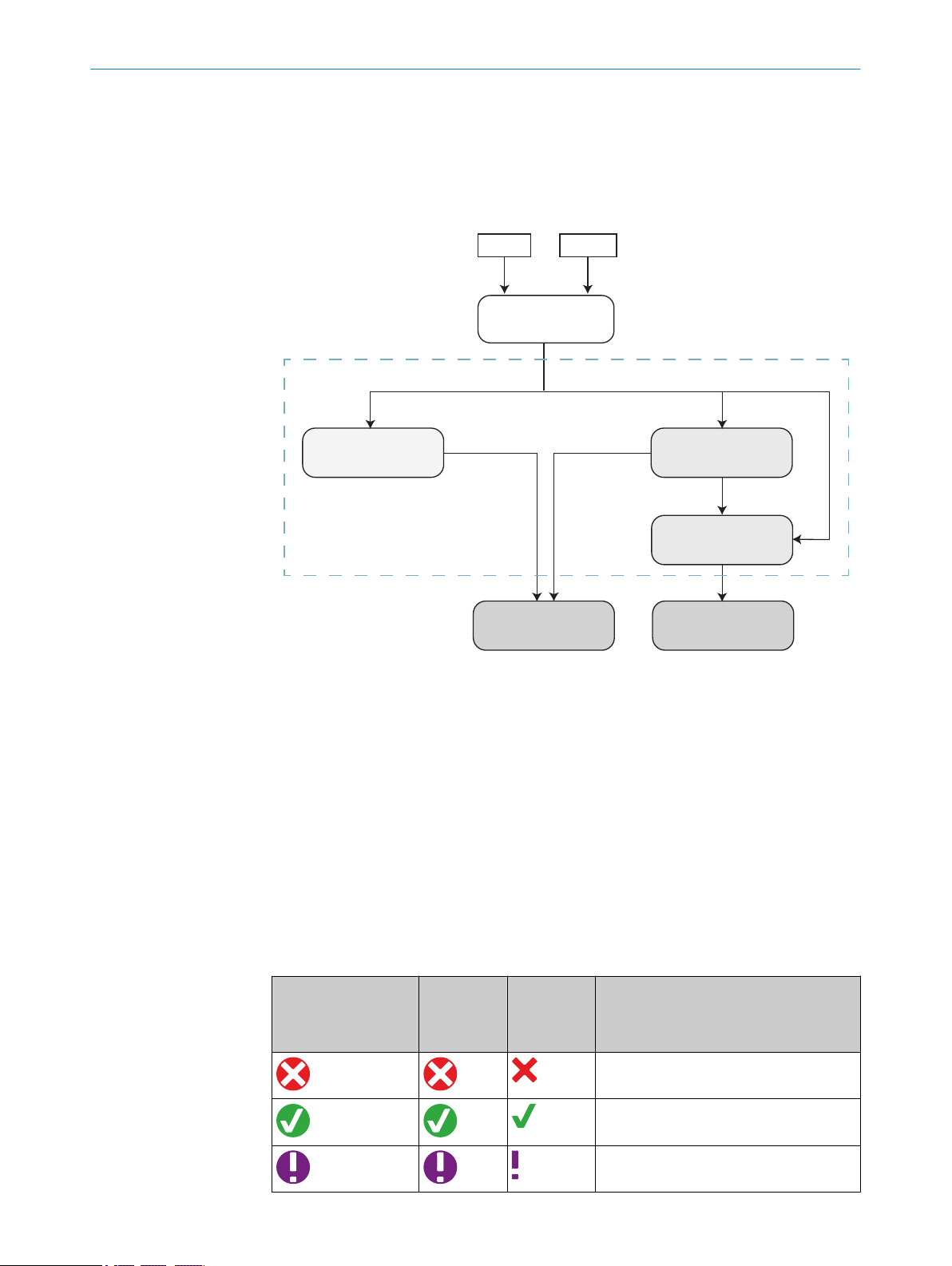
7.7 Results workflow step
Analysis
Overall decision
Digital outputs Output string
Conditions
Output string expression
Tools Image
True / FalseOK / NOK
Analysis resultAnalysis result
7.7.1 Result handling
Result handling consists of methods to define and format device output. Use cases
range from activation of a reject mechanism to output of formatted string results.
OPERATION 7
7.7.2 Tool result output
7.7.2.1 Tool result symbols
Figure 34: Overview of the result handling
Binary results are based on tool tolerances set by the user. Conditions and expressions
can be used for custom result handling without setting tolerances.
Tools return results as values (for example area: 42 mm2, angle: 12 degrees) or binary
results (OK/NOK). The binary results are controlled by tolerances set by the user in the
tool parameter pane in the Task workflow step, e.g. the number of blobs found by a Blob
tool. If no tolerances are set, the results will be returned as neutral.
The overall image result is displayed in the image area. Individual tool results are dis‐
played in the parameter pane in the Task workflow step.
Image area Tool symbol
(parameter
pane)
Not OK Result not OK.
OK Result OK.
Invalid Result invalid.
Tool result
section
(parameter
pane)
Description
8021808/12ID/2019-01 | SICK O PE R AT I NG IN S TR U CT I ON S | TriSpector1000
Subject to change without notice
43

7 OPERATION
7.7.3 Decision model
The SOPAS ET decision model applies tool tolerances to define binary results. If multi‐
ple tools are used, the tool results are combined for the overall image decision (AND
logic).
The priority for a decision is:
1 'Not Found' (one or more tool results are 'Not Found')
2 'Invalid' (one or more tool results are 'Invalid')
3 'Not OK' (one or more tool results are 'Not OK')
4 'OK' (all tool results are 'OK')
5 'Neutral' (no tool tolerances are set)
NOTE
Only 'OK' and 'Not OK' can be sent as overall decisions to the digital outputs. Other
result types can be handled by conditions, see "Condition examples", page 44.
Image area Tool symbol
(parameter
pane)
Not found Result not found.
Neutral Result neutral (no tolerances set).
Tool result
section
(parameter
pane)
Description
7.7.4 Conditions
In the Conditions section, the results from the Task workflow step are used to create
true/false expressions.
"Condition examples", page 44 and "Handling arrays by conditions", page 45 con‐
tain examples of conditions for mathematical operations, result checks and array han‐
dling. Use the results as digital output, for creation of result strings or as input to other
conditions.
Creating a condition
Figure 35: Creating a condition
1. Click the New button and name the condition.
2. Edit the condition in the condition editor, either by typing or by inserting parame‐
ters from the +Result and +Func lists.
■
The +Result list contains image analysis results and tool result output.
■
The +Func list contains supported functions and operators.
7.7.4.1 Condition examples
44
O PE R AT I NG IN S TR U CT I ON S | TriSpector1000 8021808/12ID/2019-01 | SICK
Subject to change without notice

OPERATION 7
Example 1: Rotation
This condition returns true if the Rotation output from the Shape0 tool is between 5 and
10 degrees.
Example 2: Decision
This condition returns true if the overall decision (for all tools) is 'Not found' or if the
number of blobs from the Blob1 tool is not equal to 20.
Example 3: Calculate angle
This condition returns true if the angle from the Plane1 tool in the XZ plane is less than
20 degrees.
Plane 1.Nx returns the X component of the normal vector for the plane, while Plane 1.Nz
returns the Z component. The atan() function returns the value of the angle from the Z
axis, in radians. The deg() function converts the value to degrees and returns a positive
value in the interval [0, 360].
Example 4: Condition inside condition
This condition returns true if the condition NewCondition2 returns true or if the Distance
output from the Distance1 tool is less than 50 mm. When using conditions inside condi‐
tions, make sure not to create a circular dependency.
7.7.4.2 Handling arrays by conditions
In the examples below, conditions are used to create and handle arrays. Array handling
is useful for the Blob tool, which returns most results as arrays with one element for
each found blob.
Example 1: Maximum value
This condition returns true if the maximum value in the Blob 0.area[] array is smaller
than 50 mm2.
Example 2: Single element
This condition returns true if the fourth element (the element with index 3) in the
Blob0.blobAngle[] array has a positive value.
The element() function accesses a specified element in the array. Note that the first ele‐
ment in the array has index 0.
8021808/12ID/2019-01 | SICK O PE R AT I NG IN S TR U CT I ON S | TriSpector1000
Subject to change without notice
45

7 OPERATION
NOTE
The condition returns an error if the array contains less than 4 blobs, which means that
neither a true or false value is returned.
Example 3: Check each element
This condition returns true if the X-center of each blob in the Blob0.cogX[] array is in the
interval [-50, 50].
Example 4: Create array
This condition returns true if the distance between the Z coordinates of four Peak tools
is greater than 1 mm.
The array() function creates an array containing the Z values for four Peak tools. The
minimum and maximum values in the array are then compared.
7.7.5 Digital outputs
Use the Digital outputs section to specify which results to send to the available outputs.
The outputs must first be enabled in the I/O Definitions section in the Interfaces workflow
step.
Digital outputs can be activated based on the following:
■
Device ready.
■
Result ready.
■
The overall image decision (OK/NOK).
■
Conditions (True/False)
7.7.6 Ethernet output string
Use the Ethernet output string section to define a result string, based on e.g. a boolean
tool decision or a condition.
■
The +Prog list contains statements (For each, If, Str).
■
The +Char list contains ASCII characters.
■
The +Result list contains available image analysis results and tool decisions.
■
The +Func list contains supported functions and operators.
46
Figure 36: Example of result string
O PE R AT I NG IN S TR U CT I ON S | TriSpector1000 8021808/12ID/2019-01 | SICK
Subject to change without notice

7.7.7 Image logging
OPERATION 7
In figure 36, the coordinates of the first blob are returned if the BlobAnglePlusMinus10De‐
grees condition evaluates as true. If the condition evaluates as false, zero coordinates
are returned.
The result string can be sent as output via Ethernet/IP, TCP/IP or the serial interface. To
enable output via TCP/IP or the serial interface, select the applicable Output string
checkbox in the Interfaces workflow step.
The Image logging section specifies which log condition to use when logging images to an
FTP server or a microSD memory card.
NOTE
The log conditions lists are only enabled when image logging is active. To activate
image logging, select the FTP image logging checkbox or the SD Card image logging check‐
box in the Interfaces workflow step.
NOTE
The Image logging section does not indicate whether the image transfer was successful.
To check the status of the connection to the FTP server, see "Setting parameters of the
Ethernet interface".
The following log conditions are available:
1. None - Log no images.
2. All - Log all images.
3. Overall result - Log images where the overall decision is 'OK' or 'Not OK'.
4. Conditions - Log images based on a created condition (see "Conditions", page 44).
7.7.8 Functions and operators
The TriSpector1000 supports a set of operators and functions for result handling. The
categories of operators and functions are mathematical, logical and strings.
7.7.8.1 Logical operators
Table 4: Logical operators
Operator Syntax Result
< x < y BOOL Smaller than
> x > y BOOL Larger than
<= x <= y BOOL Smaller than or equal to
>= x >= y BOOL Greater than or equal to
= x = y BOOL Equal to
~= x ~= y BOOL Not equal to
and x and y BOOL Logical and
or x or y BOOL Logical or
not not(x) BOOL Logical not of a boolean x
Description
type
8021808/12ID/2019-01 | SICK O PE R AT I NG IN S TR U CT I ON S | TriSpector1000
Subject to change without notice
47

7 OPERATION
7.7.8.2 Logical functions
Table 5: Logical functions
Function Syntax Result
any any(array) BOOL Check if any array element is true.
all all(array) BOOL Check if all array elements are true.
count count(array) NUM Count all true values in a boolean array.
contains con‐
element ele‐
array array(x1, ...) Any Create an array of list elements, array index starts at
size size(array) NUM Calculate the size of an array.
7.7.8.3 Mathematical operators
Table 6: Mathematical operators
Operator Syntax Result
+ x + y NUM Addition
- x - y NUM Subtraction
- -x NUM Negation
* x * y NUM Multiplication
/ x / y NUM Division
^ x^y NUM Exponentiation
. x.y NUM Decimal
Description
type
BOOL Check if a value x is present in an array.
tains(array,
x)
Any Get an element out of an array by index.
ment(array,
index)
zero.
Description
type
7.7.8.4 Mathematical functions
Table 7: Mathematical functions
Functions Syntax Result
min min(x1, ...) NUM Find the minimum value in a list of elements or an array.
max max(x1, ...) NUM Find the maximum value in a list of elements or an array.
sum sum(x1, ...) NUM Sum of all elements in a list or an array.
abs abs(x) NUM Absolute value of x.
round round(x,
mod mod(x,y) NUM Calculate x modulo y.
sqrt sqrt(x) NUM Calculate the square root of x.
sin sin(x) NUM Calculate the sine of x in radians.
cos cos(x) NUM Calculate the cosine of x in radians.
tan tan(x) NUM Calculate the tangent of x in radians.
asin asin(x) NUM Calculate the arcsine of x in radians.
acos acos(x) NUM Calculate the arccosine of x in radians.
atan atan(x) NUM Calculate the arctangent of x in radians.
48
O PE R AT I NG IN S TR U CT I ON S | TriSpector1000 8021808/12ID/2019-01 | SICK
Description
type
NUM Round x to an integer or to a fixed number of decimals.
dec)
Subject to change without notice

OPERATION 7
7.7.8.5 String operators
Table 8: String operators
7.7.8.6 String functions
Table 9: String functions
Functions Syntax Result
Description
type
deg deg(rad) NUM Convert radians to degrees.
rad rad(deg) NUM Convert degrees to radians.
pow pow(x,y) NUM Calculate a to the power of b (x^y).
exp exp(x) NUM Calculate e to the power of x (e^x).
ln ln(x) NUM Calculate the natural logarithm of x.
log10 log10(x) NUM Calculate the logarithm of x (base 10).
Operator Syntax Result
Description
type
"" "x" STR String representation.
.. x .. y STR Concatenation of strings x and y.
= x = y BOOL Check if two strings x and y are equal, with wildcard func‐
tionality.
Function Syntax Result
Description
type
matches matches(str,
pat‐
tern,mode)
hasSub‐
String
hasSub‐
string(str,sub
BOOL Check if a string matches a regular expression. The
mode variable can be set to "unicode" or "binary", the
default setting is "unicode".
BOOL Check if a string contains a substring. Case sensitive.
str)
find find(str,sub‐
str)
NUM Check if a string contains a substring. Returns index of
the first character of a found substring. Case sensitive.
length length(str) NUM Calculate the length of a string in bytes.
substr sub‐
STR Get a substring from a string.
str(str,start,e
nd)
token token(str,d) Array Create an array of a string of tokens with delimiter d.
prefix pre‐
fix(str,filler,le
STR Fill the beginning of a string with a filler character up to a
specified length.
n)
postfix post‐
fix(str,filler,le
STR Fill the end of a string with a filler character up to a spec‐
ified length.
n)
roundToStr round‐
ToStr(num‐
STR Convert a number to a string, with a given number of
decimals,
ber,dec)
7.7.8.7 String wildcards
Table 10: String wildcards
Wildcard Syntax Description
* *S Any string precedes a certain string. Equal to regular expression
".*"
8021808/12ID/2019-01 | SICK O PE R AT I NG IN S TR U CT I ON S | TriSpector1000
Subject to change without notice
49

7 OPERATION
Wildcard Syntax Description
? ?S Any character precedes a certain string. Equal to regular expres‐
7.8 Interfaces workflow step
7.8.1 Configuring the digital in- and outputs
The digital I/O interfaces are available on the Power I/O connector, see "Pin assign‐
ment", page 20. I/O 4, 5, 6 and 7 are configurable and can be used for either input or
output signals.
Configure I/O as input
1. Set the Type parameter in the I/O Definitions table to In.
2. Set the input signal level (Active parameter) to High (24 V) or Low (0 V).
3. Set the minimum input signal length by the Debounce parameter (1 ms is default).
Configure I/O as output
1. Set the Type parameter in the I/O Definitions table to Out.
2. Set the output signal level (Active parameter) to High (24 V) or Low (0 V).
sion ".?"
Once an I/O has been configured as output, its output signal can be set in the Digital
outputs section in the Results workflow step.
7.8.2 Using the command channel
A command channel is a camera interface which is used for external modification
of image and tool parameter settings. The following command channel interfaces are
available for the TriSpector1000:
■
Ethernet (TCP/IP).
■
Serial.
■
EtherNet/IP, see "Setting up a TriSpector1000 to communicate via EtherNet/IP",
page 73.
See "Available commands for command channel", page 67 for a full list of available
commands.
To use TCP/IP as command channel interface:
1. Select the Command channel checkbox in the Ethernet section in the parameter pane.
2. In the Server/client drop-down menu, select to act as server or client (depending on
the settings of the connected device).
3. Set port number in the TCP Port text field. 2115 is the default port.
To use the serial interface as command channel interface:
1. Select the Command channel checkbox in the Serial section in the parameter pane.
7.8.3 Sending an output string
The following interfaces are available for sending an output string from the TriSpec‐
tor1000 to a connected device:
■
Ethernet (TCP/IP).
■
Serial.
■
Ethernet/IP, see "Setting up a TriSpector1000 to communicate via EtherNet/IP",
page 73.
50
O PE R AT I NG IN S TR U CT I ON S | TriSpector1000 8021808/12ID/2019-01 | SICK
Subject to change without notice

Define the output string in the Ethernet output string section in the Results workflow step,
see "Ethernet output string", page 46 for details.
To send the output string via TCP/IP:
1. Select the Output string checkbox in the Ethernet section in the parameter pane.
2. In the Server/client drop-down menu, select to act as server or client (depending on
the settings of the connected device).
3. Set the port number in the TCP Port text field. 2114 is the default port.
To send the output string via the serial interface:
1. Select the Output string checkbox in the Serial section in the parameter pane.
7.8.4 Logging images to an FTP server
To log images to an FTP server:
1. Select the FTP image logging checkbox in the Ethernet section in the parameter pane.
2. Specify the IP address, port, username and password to connect to an FTP server.
3. Test the connection to the server by clicking the Test connection button.
✓
A message with the connection status appears in the GUI.
4. Specify the log condition in the Image logging section in the Results workflow step,
see "Image logging", page 47.
OPERATION 7
The logged images are saved in Portable Network Graphics (.png) format, and contain
both height data and reflectance data.
Destination folder
If the Path field in the FTP image logging section is empty, images are saved to the speci‐
fied folder on the FTP server. To create a sub-folder and save the images there, define
the path to the sub-folder in the Path field.
7.8.5 Enabling the web interface
Enable the Webserver option to view the images acquired by the TriSpector1000 in a web
browser. Google Chrome is recommended as web browser due to advanced support of
WebGL and web sockets.
NOTE
In order to access the web interface, the computer and the TriSpector1000 must be on
the same subnet.
To view images in a web browser:
1. Select the Webserver checkbox in the Ethernet section in the parameter pane.
2. Open a web browser window.
3. Type the IP address of the TriSpector1000 in the address field.
The page displayed in the web browser views the live 3D image, the name of the current
job, the image number, the results for all applied tools and the overall image decision.
Use the eye symbol above the image area to show the applied tools as overlay to the
image.
NOTE
If the error message 'Webserver not enabled' appears in the web browser, it means that
the Webserver checkbox in SOPAS is not selected.
8021808/12ID/2019-01 | SICK O PE R AT I NG IN S TR U CT I ON S | TriSpector1000
Subject to change without notice
51

7 OPERATION
7.8.6 Setting parameters of the serial interface
The serial interface is available on the Power I/O connector, see "Pin assignment",
page 20. The following parameters can be set:
■
Baud rate: Data rate, in bits per second (bps).
■
Data bits: The number of data bits.
■
Stop bits: The number of stop bits.
■
Parity: Whether to use parity (odd or even).
Command channel
Select the Command channel checkbox to use the serial interface as command channel.
see "Using the command channel", page 50 for more information.
Output string
Select the Output string checkbox to send a result string via the serial interface. see
"Sending an output string", page 50 for more information.
7.8.7 Logging images to a microSD memory card
Follow the instructions below to log images to a microSD memory card:
NOTE
If no microSD memory card is inserted or if there is not enough memory available, no
images are logged. The images currently stored on the SD card are not overwritten.
1. Select the SD card image logging checkbox in the SD Card section in the Interfaces
workflow step to activate the image logging.
2. Specify the log condition in the Image logging section in the Results workflow step,
see "Image logging", page 47.
The logged images are saved in Portable Network Graphics (.png) format, and contain
both height data and reflectance data.
Destination folder
The first time an image is logged, a default folder named TriSpectorImages is cre‐
ated on the microSD memory card. If the Path field in the SD Card section is empty, all
images are saved to the default folder. To create a sub-folder and save the images
there, define the path to the sub-folder in the Path field.
Options
The following options are available in the SD Card section:
Click SD Card Info to view the currently available memory on the microSD memory
•
card.
Click Export images to export all images in the default folder and the underlying sub-
•
folders from the microSD memory card to the PC.
Click Delete all images to delete all images from the default folder and the underly‐
•
ing sub-folders on the microSD memory card.
Click Eject to stop all access to the data on the microSD memory card before
•
removing the card from the device.
52
Monitoring the log status
Three parameters related to the image logging are available for the Conditions and Ether‐
net output string sections in the Result workflow step:
O PE R AT I NG IN S TR U CT I ON S | TriSpector1000 8021808/12ID/2019-01 | SICK
Subject to change without notice

OPERATION
ImageQueueLength (the number of images placed in the log queue)
•
MaxImageQueueLength (the maximum number of images which can be placed in log
•
queue)
AvailableMemory (the available memory on the microSD memory card)
•
Use the above parameters to create conditions for monitoring the image logging, see
figure 37 and figure 38 for examples. For further information on how to create and use
conditions, see "Conditions", page 44.
7
Figure 37: Example of a condition which returns true if the available memory on the microSD
card is less than 10 MB
Figure 38: Example of a result output string which contains the available memory on the
microSD card (in bytes)
8021808/12ID/2019-01 | SICK O PE R AT I NG IN S TR U CT I ON S | TriSpector1000
Subject to change without notice
53

7 OPERATION
7.8.8 Selecting jobs via digital inputs
Figure 39: Job Selection Input section
The Job Selection Input section enables job selection via digital input signals. The number
of available inputs depend on the number of I/O configured as inputs in the I/O Defini‐
tions section, see "Configuring the digital in- and outputs", page 50.
NOTE
The input signals must be kept high during the whole session, not only when the job is
initiated.
■
Each row in the list represents a unique combination of available inputs.
■
Select a job in the Job drop-down list to match it with a set of inputs.
■
Click the Auto-fill button to include all available jobs in the list (one job per row).
■
Click the Clear button to remove all jobs from the list.
7.8.9 Fieldbuses
The TriSpector1000 has native EtherNet/IP support. To connect the TriSpector1000 to
a PROFINET network, use the fieldbus module CDF600-2200 from SICK. See "Connect‐
ing TriSpector1000 to CDF600-2200", page 72 for details.
7.9 Using the SOPAS ET emulator
Use the SOPAS ET emulator to simulate and test device settings off-line without access
to a real TriSpector1000. The main differences when using the emulator compared to a
real device are:
■
Images will not be affected by changes made in the Image workflow step.
■
Processing times may differ, since the emulator uses the PC hardware instead of
the device hardware.
■
The digital I/O connections are disabled.
7.9.1 Starting the emulator
There are two ways to start the emulator:
■
Starting the emulator when connected to a TriSpector1000.
■
Starting the emulator when starting SOPAS ET (without PC application running).
54
O PE R AT I NG IN S TR U CT I ON S | TriSpector1000 8021808/12ID/2019-01 | SICK
Subject to change without notice

OPERATION 7
NOTE
The emulators are available via the SOPAS Device Drivers (SDD). An SDD is installed at
the first use of the TriSpector1000. If no SDD is installed, the Emulators tab in SOPAS
ET will be empty and the SDD must be installed manually, as described below.
Starting the emulator when connected to a TriSpector1000
1. In the SOPAS ET device window, click Switch to Simulated Device on the Device menu.
Starting the emulator when starting SOPAS ET
1. In the SOPAS ET main window, in the device pane, click the Emulators tab.
Figure 40: Emulators tab
2. Select the emulator corresponding to the suitable TriSpector1000 variant and click
Add.
3. Double-click the emulator icon in the project pane to start the configuration.
Installing an SDD
1. In the SOPAS ET main window, in the device pane, click the Device catalog tab.
2.
Click the Device driver management button ( ).
✓
The Device driver management window opens.
3. Select the Install option and click Next.
4. Select www.mysick.com as source and click Next.
5. In the Search device field, type TriSpector.
✓
All available TriSpector1000 SDDs appear in the drivers list.
6. Select the TriSpector1000 variant and the version to install (the latest version is
recommended) and click Next.
✓
The installation starts.
7. When the installation is complete, click Finish.
✓
The emulators are now listed under the Emulators tab.
7.9.2 Controlling the emulator
The emulator buttons above the image area control the emulator. These buttons are
only visible when using the emulator.
Run, loops through the images in the selected folder.
Pause, pauses on the current image.
Next image, steps to the next image and pauses.
8021808/12ID/2019-01 | SICK O PE R AT I NG IN S TR U CT I ON S | TriSpector1000
Subject to change without notice
55

7 OPERATION
Previous image, steps to the previous image and pauses.
First image, steps to the first image in the series and pauses.
Choose image folder, lets the user select images to be used in the emulator.
Settings for viewing the image series, including repeat (on/off) and viewing
time.
7.9.3 Selecting images to be used
Click the Choose image folder button to select images to use in the emulator. The images
must be Portable Network Graphics (.png) files acquired by a TriSpector1000.
NOTE
When selecting an image in the Choose image folder window, all images in the folder will
be used in the emulator, not only the selected image.
To save images from the TriSpector1000 to PC, see "Recording images", page 32.
7.9.4 Copying a configuration from the emulator
When connected to a TriSpector1000
If the emulator was started by using the Switch to simulated device option:
1. In the SOPAS ET device window, click Switch to physical device on the Device menu.
When not connected to a TriSpector1000
If the emulator was started from the SOPAS ET main window:
1. In the SOPAS ET device window, click Export... on the Device menu.
✓
The Device Export window opens.
2. Save the configuration as a SOPAS ET (.sopas) file.
3. Connect to the TriSpector1000 from the SOPAS ET main window.
4. Load the configuration by clicking Import... on the Device menu.
NOTE
To save an imported configuration in the device´s flash memory, click Save permanent on
the Parameter menu.
7.10 Exporting and importing data
Use the Export and Import functions in the SOPAS ET device window to export and import
TriSpector1000 configurations between the device and a PC.
Exporting a configuration to a PC
56
1. In the SOPAS ET functions panel, on the Device menu, click Export...
✓
The Device Export window opens.
2. Select file name and destination folder on the PC.
3. In the Save as type list, select SOPAS (*.sopas) SOPAS ET file.
4. Click Save.
Importing a configuration from a PC
1. In the SOPAS ET functions panel, on the Device menu, click Import...
✓
The Import window opens.
O PE R AT I NG IN S TR U CT I ON S | TriSpector1000 8021808/12ID/2019-01 | SICK
Subject to change without notice

OPERATION 7
2. Select a configuration (.sopas) file and click Open.
3. To save the configuration, click Save permanent on the Parameter menu.
✓
The configuration is saved to the device flash memory. If the device has a microSD
memory card inserted, the configuration is saved to both the flash memory and
the microSD memory card.
8021808/12ID/2019-01 | SICK O PE R AT I NG IN S TR U CT I ON S | TriSpector1000
Subject to change without notice
57

8 MAINTENANCE
8 Maintenance
8.1 Cleaning
To maintain the reading performance of the TriSpector1000, it is necessary to keep
the camera window and the laser window clean. Check the windows for contamination
such as dust or moisture regularly. Clean with a damp and soft cloth and use a mild
cleaning agent if necessary.
For the TriSpector1000 PMMA variants, the windows can attract dust particles due to
static charge. Use the SICK anti-static plastic cleaning agent (no. 5600006) in combina‐
tion with the SICK lens cloth (no. 4003353) to reduce this effect.
NOTE
No maintenance is required to ensure compliance with the laser class.
8.2 Upgrading the firmware
The latest firmware for the TriSpector1000 can be downloaded from the SICK Support
Portal.
To upgrade the firmware:
1. Log in to the SICK Support Portal.
2. Under the Vision tab, select TriSpector1000 and navigate to the Firmware download for
TriSpector1000 page.
3. Download the firmware package file (FWP file format) and the firmware key file
(KEY file format).
4. Follow the instructions on the page to install the firmware.
NOTICE
Old firmware for the TriSpector1000 is available on the SICK Support Portal and can be
used to downgrade the device. Before downgrading, make sure all application parame‐
ters are reset to default:
1. Click Load application defaults on the Functions menu.
2. Click Save permanent on the Parameter menu.
Failure to reset the parameters might result in a device that does not boot and needs
re-flashing.
8.3 Data backup and restoration
Creating a back-up of a configuration
Use the Export function in SOPAS ET to create a back-up of a TriSpector1000 configura‐
tion and save to a PC, see "Exporting and importing data", page 56. Use the Import func‐
tion to re-import the configuration into SOPAS ET.
58
Resetting parameters to default
To reset all SOPAS ET parameters including IP address:
1 Click Load factory defaults on the Functions menu.
2 Click Save permanently on the Parameter menu.
To reset all SOPAS ET parameters except IP address:
1 Click Load application defaults on the Functions menu.
2 Click Save permanently on the Parameter menu.
O PE R AT I NG IN S TR U CT I ON S | TriSpector1000 8021808/12ID/2019-01 | SICK
Subject to change without notice

9 Troubleshooting
9.1 General faults, warnings, and errors
Possible errors and corrective actions are described in the table below. In the case of
errors that cannot be corrected using the information below, please contact the SICK
Service department. To find your agency, see the back page of this document.
NOTE
Before calling, make a note of all type label data such as type designation, serial num‐
ber, etc., to ensure faster telephone processing.
Table 11: Troubleshooting questions and answers
Question Possible cause and resolution
The result is invalid. The Shape, Plane, Edge and Peak tools require image data inside
their region of interest to work.
b
The Shape tool is unable to find any edges inside its region of inter‐
est.
b
For a Shape tool, the result might become invalid if the Profile dis‐
tance parameter is changed after the job image is saved. If a
Shape tool result is invalid, the results for all tools linked to it will
also be invalid.
The laser LED is on, but
there is no laser.
The Shape tool does not
find the object, it returns
"Not Found".
A reflective surface reflects
the laser light, so it is diffi‐
cult to get a good image.
The laser module has a protection circuit and will shut itself down
if it detects a voltage spike. Such a voltage spike is common if the
TriSpector1000 is powered on by mechanically plugging in an
already powered 24 V contact into the device.
b
The object contains areas with noise, or areas which change from
sample to sample.
b
b
b
b
Tilt the TriSpector1000 to adjust the camera-laser angle.
b
b
The TriSpector1000 coordinate system also tilts when tilting the
device, so height measurements in mm are no longer valid.
TROUBLESHOOTING 9
In Job mode, make sure that the regions of interest are placed
correctly in 3D space.
Try increase the robustness slider, or include a larger portion of
the image for the Shape tool.
When all cables are connected, make sure that the power
source is stable and that a power switch is used to power
on the TriSpector1000.
Only use the Shape tool on edges that are present in all live
images.
In the tool parameter pane, in the Masks section, apply a mask
to exclude unwanted parts of the object.
Increase the robustness of the Shape tool.
Decrease the edge threshold of the Shape tool to include more
edges for matching. Do not include noise or areas that can
change.
To get more data from reflective surfaces, tilt the TriSpec‐
tor1000 forward. A more specular camera-laser angle will
result in more light entering the camera.
To avoid noise due to a reflective surface, tilt the TriSpec‐
tor1000 backwards for a more look-away camera-laser angle.
8021808/12ID/2019-01 | SICK O PE R AT I NG IN S TR U CT I ON S | TriSpector1000
Subject to change without notice
59

9 TROUBLESHOOTING
9.2 Repairs
9.3 Returns
Question Possible cause and resolution
It is difficult to get data at
the bottom of a hole
The TriSpector1000 is only
receiving every 2nd (3rd,
4th...) image
By tilting the TriSpector1000 forward or backwards, different parts
of the hole can be seen.
The TriSpector1000 coordinate system also tilts when tilting the
device, so height measurements in mm are no longer valid.
Triggers which arrive while the image acquisition is still ongoing
will be discarded as overtrigs and no new image acquisition will
start.
Reduce the image acquisition time by decreasing the Length
b
parameter in the Image workflow step.
Repair work on the device may only be performed by qualified and authorized person‐
nel from SICK AG. Interruptions or modifications to the device by the customer will inval‐
idate any warranty claims against SICK AG.
Do not dispatch devices to the SICK Service department without consultation.
b
9.4 Disposal
NOTE
To enable efficient processing and allow us to determine the cause quickly, please
include the following when making a return:
■
Details of the contact person
■
Description of the application
■
Description of the fault that occurred
CAUTION
Risk of injury due to hot device surface!
In analysis mode, the surface of the device (particularly at the rear) can reach tempera‐
tures of up to 70 °C.
Before commencing disassembly, switch off the device and allow it to cool down
b
as necessary.
Any device which can no longer be used at the end of the product life cycle must be
disposed of in an environmentally friendly manner in accordance with the respective
applicable country-specific waste disposal regulations. As they are categorized as elec‐
tronic waste, the device must never be disposed of with household waste.
ATTENTION
Danger to the environment due to improper disposal of the product!
Disposing of the product improperly may cause damage to the environment.
Therefore, take note of the following information:
60
Always observe the valid regulations on environmental protection.
b
Following correct disassembly, pass on any disassembled components for reuse.
b
Separate the recyclable materials by type and place them in recycling containers.
b
O PE R AT I NG IN S TR U CT I ON S | TriSpector1000 8021808/12ID/2019-01 | SICK
Subject to change without notice

10 Technical data
10.1 Features
Attribute Value
Tasks Positioning, inspection, measurement
Technology 3D, line scan, image analysis
Working distance (measured from front win‐
dow)
Width at minimum working distance 1008: 40 mm
Width at maximum working distance 1008: 75 mm
Maximum height range 1008: 60 mm
Light source Visible red light (laser, 660 nm)
Laser class 2 (EN/IEC 60825-1:2014)
Laser fan angle 45°±2°
Imaging angle 1008/1030: 65°
Offline support Emulator
Toolset Angle, Area, Blob, Distance, Edge, Fix Plane,
TECHNICAL DATA 10
1008: 56...116 mm range
1030: 141...541 mm range
1060: 291...1091 mm range
1030: 90 mm
1060: 180 mm
1030: 330 mm
1060: 660 mm
1030: 400 mm
1060: 800 mm
2M (EN/IEC 60825-1:2007)
Complies with 21 CFR 1040.10 except for
deviations pursuant to Laser Notice No. 50,
dated June 24, 2007
1060: 67°
Plane, Peak, Point, Shape
10.2 Ambient data
Attribute Value
Shock load 15 g / 6 ms (EN 60068-2-27)
Vibration load 5 g, 10 Hz...150 Hz (EN 60068-2-6)
Ambient operating temperature 0 °C ... +40 °C (adequate heat dissipation is
required, see "Mounting instructions", page 16)
Ambient storage temperature –20 °C ... +70 °C
Permissable relative air humidity 0% ... 90%, non-condensing
10.3 Interfaces
Attribute Value
Operator interface SOPAS
Configuration software SOPAS
Communication interfaces Gigabit Ethernet (TCP/IP), serial (RS-232), con‐
figurable digital I/O
Digital inputs 3 x, non-isolated
8021808/12ID/2019-01 | SICK O PE R AT I NG IN S TR U CT I ON S | TriSpector1000
Subject to change without notice
61

10 TECHNICAL DATA
Attribute Value
Digital in-/ outputs 4 x, non-isolated, configurable
Encoder interface RS-422/TTL (DBS36E-BBCP02048)
Maximum encoder frequency 300 kHz
Fieldbuses Ethernet/IP via Gigabit Ethernet port
10.4 Mechanics and electronics
Attribute Value
Power I/O M12 male connector, 12-pin A-coded
Gigabit Ethernet M12 female connector, 8-pin X-coded
Encoder M12 female connector, 8-pin A-coded
Connector material Brass, nickel-plated
Supply voltage 24 V DC, ± 20 %
Supply current 1.5 A maximum; external fuse required
Power consumption 11 W maximum
Ripple < 5 Vpp
Current consumption 400 mA with no output loads
Enclosure rating IP 67
Safety EN 60950-1:2014-08
Protection class III
EMC Immunity: EN 61000-6-2:2005
Weight (not including cables) 1008: 900 g
Dimensions (L x W x H) 1008: 136 mm x 62 mm x 84 mm
Optics Fixed
ProfiNet via serial interface connected to SICK
module CDF600-2200
SELV + LPS according to EN 609501:2014-08 or Class 2 according to
UL1310 (6th edition)
Emission: EN 61000-6-3:2007
1030: 1300 g
1060: 1700 g
1030: 217 mm x 62 mm x 84 mm
1060: 307 mm x 62 mm x 84 mm
10.5 Input switching levels
Attribute Value
Input levels Up to 30 V
Input threshold levels High: > 15.0 V
Hysteresis > 1.0 V
Input current High: < 3.0 mA
62
O PE R AT I NG IN S TR U CT I ON S | TriSpector1000 8021808/12ID/2019-01 | SICK
Stresses beyond this over-voltage level can
cause permanent damage to the device.
Low: < 5.0 V
Low: < 0.1 mA
Subject to change without notice

10.6 Output switching levels
Attribute Value
Voltage level high High: > Voltage Supply - 3.0 V
Source/sink output current ≤ 100 mA at 24°C
Overcurrent protection < 200 mA
Capacitive load ≤ 100 nF
Inductive load ≤ 1H (with use of external free-wheeling diode,
10.7 Performance
Attribute Value
Typical height resolution (Near field/Far field) 1008: 20/50 μm
Maximum performance 2000 3D profiles/s
Maximum number of profiles 2500 per image
3D profile resolution 1008: 0.049 mm/px
TECHNICAL DATA 10
(Voltage Supply = 19.2 V...28.8 V)
Low: < 2.0 V
otherwise permanent damage to the device
can occur)
1030: 40/280 μm
1060: 80/670 μm
1030: 0.215 mm/px
1060: 0.43 mm/px
8021808/12ID/2019-01 | SICK O PE R AT I NG IN S TR U CT I ON S | TriSpector1000
Subject to change without notice
63

11 ACCESSORIES
11 Accessories
NOTE
Accessories and where applicable mounting information can be found online at:
•
www.sick.com/TriSpector1000
64
O PE R AT I NG IN S TR U CT I ON S | TriSpector1000 8021808/12ID/2019-01 | SICK
Subject to change without notice

12 Appendix
12.1 Declarations of conformity
The EU declaration of conformity for the TriSpector1000 series vision sensor can be
found online on the device webpages at: www.sick.com
APPENDIX 12
8021808/12ID/2019-01 | SICK O PE R AT I NG IN S TR U CT I ON S | TriSpector1000
Subject to change without notice
65

12 APPENDIX
12.2 Licenses
SICK uses open-source software. This software is licensed by the rights holders using
the following licenses among others: the free licenses GNU General Public License (GPL
Version2, GPL Version3) and GNU Lesser General Public License (LGPL), the MIT
license, zLib license, and the licenses derived from the BSD license.
This program is provided for general use, but WITHOUT ANY WARRANTY OF ANY KIND.
This warranty disclaimer also extends to the implicit assurance of marketability or suit‐
ability of the program for a particular purpose.
More details can be found in the GNU General Public License. View the complete
license texts here: www.sick.com/licensetexts. Printed copies of the license texts are
also available on request.
66
O PE R AT I NG IN S TR U CT I ON S | TriSpector1000 8021808/12ID/2019-01 | SICK
Subject to change without notice

12.3 Available commands for command channel
12.3.1 Sending a command
■
Add the command delimiter bytes stx (0x02) and etx (0x03) to mark the begin‐
ning and end of a command.
■
Use single spacing between a command and an argument, and between argu‐
ments.
■
Use quoted text for string arguments and unquoted text for all other argument
types.
12.3.2 Command examples
Select a job:
<stx>set job "job0"<etx>
Enable object triggering:
<stx>set imageTriggerMode Object<etx>
Get all settings for a tool named "Fix Plane 1":
<stx>get tool "Fix Plane 1"<etx>
APPENDIX 12
Get the XZ Angle for a fixed plane tool named "Fix Plane 1":
<stx>get tool "Fix Plane 1" XZAngle<etx>
Set the XZAngle for a fixed plane tool to 42.0:
<stx>set tool "Fix Plane 1" XZAngle 42.0<etx>
12.3.3 General commands
Command Arguments Returns Description
set job string: job-name result Select active job, by name.
get job string: job-name Get the name of the active
set exposure int: exposure result Set the sensor exposure
get exposure int: exposure Get the sensor exposure
set gain real: gain result Set the sensor gain factor.
get gain real: gain Get the sensor gain factor.
set imageTrigger‐
Mode
get imageTrigger‐
Mode
set laser enum: enable [on, off] result Turn the laser on or off.
set laserThresh‐
old
get laserThresh‐
old
set profileDis‐
tance
job.
time, in microseconds.
time, in microseconds.
enum: imageTriggerMode
[Input, None, Object, Com‐
mand]
int: threshold result Set the intensity threshold
real: distance result Set the distance between
result Set the image trigger
mode.
enum: imageTrig‐
gerMode [Input,
None, Object,
Command]
int: threshold Get the intensity threshold
Get the image trigger
mode.
for detecting the laser.
for detecting the laser.
profile acquisitions, in mm.
8021808/12ID/2019-01 | SICK O PE R AT I NG IN S TR U CT I ON S | TriSpector1000
Subject to change without notice
67

12 APPENDIX
Command Arguments Returns Description
get profileDis‐
tance
set profileTrigger‐
Mode
get profileTrigger‐
Mode
enum: mode [Encoder,
FreeRunning]
real: distance Get the distance between
profile acquisitions, in mm.
result Set the profile trigger
mode.
enum: mode
[Encoder,
Get the profile trigger
mode.
FreeRunning]
set encoderMode enum: mode [PositionUp,
result Set the encoder mode
PositionDown, DirectionUp,
DirectionDown, Motion]
get encoderMode enum: mode
Get the encoder mode
[PositionUp, Posi‐
tionDown, Direc‐
tionUp, Direction‐
Down, Motion]
set pulsesPerMM real: pulses result Set the number of encoder
pulses per mm. Relevant
only when profile Trigger‐
Mode is set to Encoder.
get pulsesPerMM real: pulses Get the number of encoder
pulses per mm. Relevant
only when profile Trigger‐
Mode is set to Encoder.
set speed real: speed result Specify the object move‐
ment speed, in mm/s. Rel‐
evant only when profileTrig‐
gerMode is set to FreeRun‐
ning.
get speed real: speed Get the specified object
movement speed, in mm/s.
Relevant only when pro‐
fileTriggerMode is set to
FreeRunning.
set triggerDelay‐
Time
int: delay result Specify the trigger delay in
ms. Relevant only when
triggerDelayMode is set to
ms.
get triggerDelay‐
Time
int: delay Get the trigger delay in ms.
Relevant only when trig‐
gerDelayMode is set to ms.
set triggerDelay‐
Track
int: delay result Specify the trigger delay in
mm. Relevant only when
triggerDelayMode is set to
mm.
get triggerDelay‐
Track
int: delay Get the trigger delay in
mm. Relevant only when
triggerDelayMode is set to
mm.
set triggerDelay‐
Mode
enum: mode [ms, mm] result Specify whether triggerDe‐
layTrack (mm) or triggerDe‐
layTime (ms) is used.
get triggerDelay‐
Mode
enum: mode [ms,
mm]
Get whether triggerDelay‐
Track (mm) or triggerDelay‐
Time (ms) is used.
echo string: message string: message Returns the input message.
68
O PE R AT I NG IN S TR U CT I ON S | TriSpector1000 8021808/12ID/2019-01 | SICK
Subject to change without notice

Command Arguments Returns Description
trigger Trigger an image acquisi‐
save-to-flash result Save the current configura‐
help string Retrieve command channel
set ftpImageLog‐
ging
get ftpImageLog‐
ging
12.3.4 Tool commands
The tool settings in chapter 12.3.4.1 are used as identifiers for the get tool and set
tool commands.
Command Arguments Returns Description
get tool string: tool name
set tool string: tool name
get tools tool info Get the settings and toler‐
APPENDIX 12
tion. Usable only when
imageTriggerMode is set to
Command.
tion persistently.
help text.
enum: enable [on, off] result Enables/disables FTP
image logging.
identifier: setting name
(optional)
identifier: setting name
parameter value
enum: enable
[on, off]
tool info Get either all settings and
boolean: [OK, Not
OK]
Get whether FTP image log‐
ging is enabled or not
tolerances for a tool or a
specified setting and toler‐
ance for a tool.
Set the value of a setting or
a tolerance for a tool.
ances for all tools added to
the current job
12.3.4.1 Tool settings
Find tools
Table 12: Shape tool
Setting Data type Value range
MinEdgeThreshold real 0.1, 100
MinScoreTolerance int 0, 100
MinSearchScore int 0, 100
Robustness int 0, 100
Rotation int 0, 180
RotationTolerance realrange -180, 180
Table 13: Blob tool
Setting Data type Value range
Accuracy int 0, 3
Area realrange 0.04, 10000
BoundingBoxType enum SmallestEnclosing, UsingBlobAngle
CalculateAngles boolean true, false
CalculateBounds boolean true, false
CutOffDirection enum NotSet, Above, Below
CutOffPlaneTool PlaneRef -
8021808/12ID/2019-01 | SICK O PE R AT I NG IN S TR U CT I ON S | TriSpector1000
Subject to change without notice
69

12 APPENDIX
Setting Data type Value range
Erode int 0, 10
ExcludeBorderBlobs boolean true, false
FillHoles boolean true, false
InvertBlobs boolean true, false
NumBlobsTolerance intrange 0, 250
ShowBlobMarkers boolean true, false
SortBy enum Area, X, Y
SortDirection enum Ascending, Descending
VolumeBound enum Disabled, Bottom, Plane
VolumePlaneTool PlaneRef -
VolumeTolerance realrange 0, 3000
Table 14: Edge tool
Setting Data type Value range
EdgeSide enum High, Low
EdgeThreshold real 0.1, 100
MeanDeviationTolerance realrange 0, 10
MinScoreTolerance int 0, 100
OutlierDistance real 0.01, 20
OutlierMode enum Auto, Manual
Polarity enum Any, Positive, Negative
ProbeSpacing int 1, 20
Selection enum Strongest, First, Last
Sharpness int 1, 10
Table 15: Plane tool
Setting Data type Value range
MinScoreTolerance int 0, 100
Offset real -60, 60
Percentile intrange 0, 100
Robustness int 10, 100
ShowUsedPoints boolean true, false
TiltTolerance realrange 0.0, 90.0
Table 16: Fix Plane tool
Setting Data type Value range
PositionX real -40,40
PositionY real 0, 400
PositionZ real -20, 80
XZAngle real -89, 89
YZAngle real -89, 89
Table 17: Peak tool
Setting
Data type Value range
HeightTolerance realrange -
KernelSize int 2, 6
70
O PE R AT I NG IN S TR U CT I ON S | TriSpector1000 8021808/12ID/2019-01 | SICK
Subject to change without notice

Setting Data type Value range
Type enum Max, Min
UseMedianFilter boolean true, false
Table 18: Point tool
Setting Data type Value range
PositionX real -1000, 1000
PositionY real -1000, 1000
PositionZ real -1000, 1000
Inspect tools
Table 19: Area tool
Setting Data type Value range
CoverageTolerance realrange 0, 100
IntensityRange intrange 0, 255
UseIntensity boolean true, false
Measure tools
APPENDIX 12
Table 20: Distance tool
Setting Data type Value range
DistanceTolerance realrange 0, 700
FeatureA FeatureRef -
FeatureB FeatureRef -
MeasureInX boolean true, false
MeasureInY boolean true, false
MeasureInZ boolean true, false
MeasureType enum RightAngle, PointToPoint
Offset real -
Table 21: Angle tool
Setting Data type Value range
AngleTolerance realrange 0, 180
FeatureA PlaneRef -
FeatureB PlaneRef -
8021808/12ID/2019-01 | SICK O PE R AT I NG IN S TR U CT I ON S | TriSpector1000
Subject to change without notice
71

APPENDIX
12
12.4 Connecting TriSpector1000 to CDF600-2200
This is an instruction for connecting the TriSpector1000 to the SICK fieldbus mod‐
ule CDF600-2200. For information about configuration and operation of the
CDF600-2200, see the CDF600-2200 quickstart (8015992).
Setting up the connection
Follow the steps below to connect the TriSpector1000 to the CDF600-2200 via the ser‐
ial (RS-232) interface.
1. Connect the pins according to the table below. Use open-ended cables and con‐
nection terminals.
Pin on TriSpector1000
(Power I/O connector)
Pin 11 Pin 2 Serial (RX to TX)
Pin 12 Pin 3 Serial (TX to RX)
Pin 2 Pin 5 GND to GND
Pin 1 Pin 1 24 V to 24 V (optional)
1
The 24 V to 24 V connection allows the TriSpector1000 to be powered by the CDF600-2200.
Pin on CDF600-2200
(DEVICE connector)
Connection type
1
2. Set the rotary encoding switch found on the side of the CDF600-2200 to "2".
Configuring the TriSpector1000
The data sent from the TriSpector1000 to the CDF600-2200 is the output string, con‐
figured in the Result workflow step in SOPAS ET. The fieldbus module will create an array
based on the string received from the TriSpector1000 and add an overhead of seven
additional characters.
To configure the TriSpector1000 for the data transmission:
1. Define the Ethernet output string in the Result workflow step in SOPAS ET.
Figure 41: Example string
2. Use the +Char list to add <STX> to the beginning of the output string and <ETX> to
the end. For an example string, "Example", the output in the output string editor
should look like figure 41.
3. Go to the Interfaces workflow step in SOPAS ET.
72
4. Enable the Output string checkbox in the Ethernet section, and choose to act as
Server on default port 2114.
O PE R AT I NG IN S TR U CT I ON S | TriSpector1000 8021808/12ID/2019-01 | SICK
Subject to change without notice
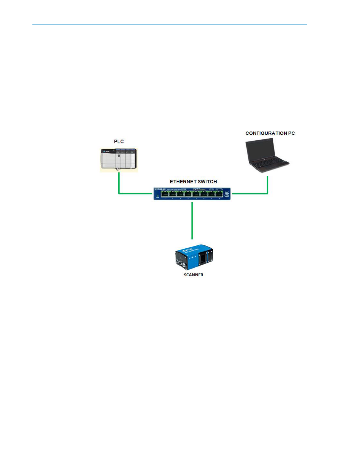
APPENDIX
12.5 Setting up a TriSpector1000 to communicate via EtherNet/IP
12.5.1 Interfacing TriSpector1000 with an Allen Bradley/Rockwell Programmable Controller
This is a procedure used to set up a TriSpector1000 to a Rockwell Automation/Allen
Bradley Controller. The hardware used:
■
SICK TriSpector1000 sensor
■
Rockwell Automation/Allen Bradley 1756-L75 ControlLogix5561 Controller
■
Rockwell Automation/Allen Bradley 1756-ENBT/A, 10/100Mbps Ethernet Bridge
■
Rockwell Automation/Allen Bradley 1756-A4 Chassis
■
Intel PC running Windows 7
The hardware is set up in a simple network as shown below.
12
The software used to configure the SICK Scanner to the Rockwell Automation/Allen
Bradley controller is:
■
SOPAS Engineering Tool (version 3.3.1 or newer)
■
RSLinx Classic Lite Version 3.71
■
Studio 5000 PLC Programming Software Version 24
The TriSpector1000 will need to be set up with an IP address. SOPAS is used to modify
the TriSpector1000’s IP Address. Once a connection is made and the device discovered
on the network, the IP Address can be modified through its tile as indicated.
8021808/12ID/2019-01 | SICK O PE R AT I NG IN S TR U CT I ON S | TriSpector1000
Subject to change without notice
73

12 APPENDIX
The TCP/IP settings will open. Here the IP Address of the device can be modified.
A static IP Address should be assigned to the TriSpector1000. If a DHCP server exists
then the TriSpector1000 can be configured to receive its IP Address.
After an IP Address has been assigned to the TriSpector1000, it can be set up/config‐
ured for the end user’s application by way of the ‘Workflow’ in the TriSpector’s device
window.
EtherNet/IP is active in the TriSpector1000. The data generated by the TriSpector1000
can be modified/configured using the TriSpector’s ‘Ethernet output string’.
The result string will appear within the programmable controller’s ‘Controller Tags’.
12.5.2 Input and Output Data Assemblies - TriSpector1000
The TriSpector1000 connects to the programmable controller over EtherNet/IP. This
connection is configured using the ‘Generic Ethernet Module’ profile.
74
O PE R AT I NG IN S TR U CT I ON S | TriSpector1000 8021808/12ID/2019-01 | SICK
Subject to change without notice
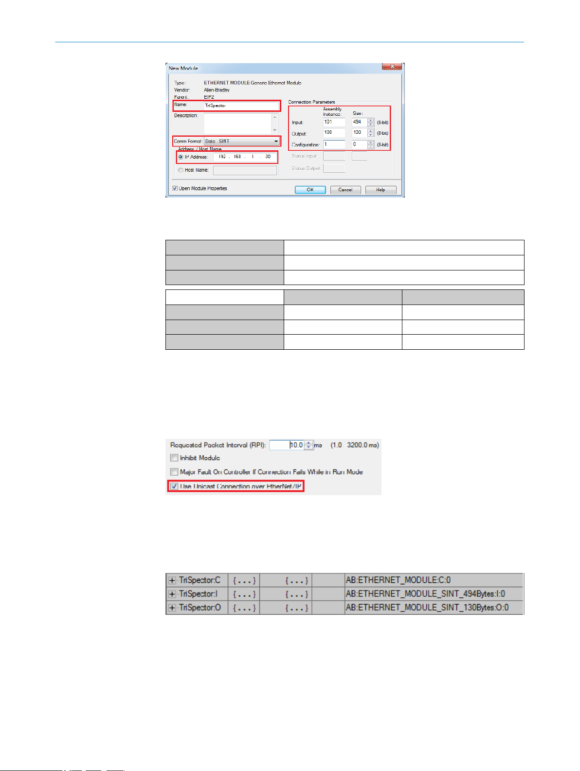
APPENDIX 12
The information required to configure the TriSpector1000 in the programmable con‐
troller consists of the following:
Name TriSpector
Comm Format Data - SINT (Single-INTeger)
IP Address 192.168.1.30
Assembly Instance Size
Input 101 494
Output 100 130
Configuration 1 0
Input is data from the TriSpector1000 to the programmable controller.
Output is data from the programmable controller to the TriSpector1000.
The data exchanged between the TriSpector1000 and the programmable controller
includes one Input Assembly Instance and one Output Assembly Instance with the sizes
shown. The Configuration Assembly is just a dummy and is not actually used. The con‐
nection will also use Unicast messaging.
After the ‘Generic Ethernet Module’ has been configured for the TriSpector1000, three
tag databases will be generated within the programmable controller’s ‘Controller Tags’.
Again, the ‘Configuration’ is a dummy and is not used. Emphasis should be placed on
the Input and Output Tag Databases generated by this ‘Generic Ethernet Module’ con‐
figuration.
12.5.2.1 Input Data Format
The Input Data Format is described in the following table. This table shows the Byte
allocation as well as the Bit description for the entire Input Data Format for the TriSpec‐
tor1000.
8021808/12ID/2019-01 | SICK O PE R AT I NG IN S TR U CT I ON S | TriSpector1000
Subject to change without notice
75

12
APPENDIX
Data type Word Bit Description Comment
Status Word BYTE 0 D0 Device Ready
D1 Input Status 1
D2 Input Status 2
D3 Input Status 3
D4 Input Status 4
D5 Input Status 5
D6 Input Status 6
D7 Input Status 7
BYTE 1 D0 Output Status 1
D1 Output Status 2
D2 Output Status 3
D3 Output Status 4
D4 Heartbeat The TriSpector1000 provides
this heartbeat bit to the fieldbus
master to show its presence
and availability on the connec‐
tion. The heartbeat will toggle
between High (1) and Low (0) in
a fixed interval.
D5 - Reserved
D6 - Reserved
D7 - Reserved
Error Code BYTE 2 Command response error code
ID BYTE 3 Command response ID
Cmd Length BYTE 4 Command response string
length
Cmd Response BYTE 5
through
BYTE 36
Result Status BYTE 37 Result string status
Result Length BYTE 38 LSB Result string length
BYTE 39 MSB
Result BYTE 40
through
BYTE 493
Command response string
Result string
76
Device Ready – The current state of the TriSpector1000 is set to 0 while booting up or
while configuring and set to 1 when the scanner is ready. “Ready” indicates that the
internal micro-processor is ready. It is not meant to be an indicator of all possible hard‐
ware faults. It will turn on, along with the “On LED”.
Input Status 1 thru 7 – Represents the current state of the digital inputs.
Output Status 1 thru 4 – Represents the current states of the digital outputs.
Heartbeat - The TriSpector1000 provides this heartbeat bit to the fieldbus master to
show its presence and availability on the connection. The heartbeat will toggle between
High (1) and Low (0) in a fixed interval.
O PE R AT I NG IN S TR U CT I ON S | TriSpector1000 8021808/12ID/2019-01 | SICK
Subject to change without notice

12.5.2.2 Output Data Format
The Output Data Format is described in the following table. This table shows the Byte
allocation for the entire Output Data Format for the TriSpector1000.
Data type Word Comment
Cmd ID BYTE 0 Command channel ID
Cmd Length BYTE 1 Command string length
Command BYTE 2
12.5.3 Inside the Programmable Controller
The TriSpector1000 will be set up in the Rockwell Automation/Allen Bradley Program‐
mable Controller as a ‘Generic Ethernet Module’.
The setup requirements for a NEW configuration (starting with hardware right out of the
box) would use Studio 5000 to start a NEW project, configure all the hardware used in
the programmable controller (i.e.: local I/O cards and communication modules), and
save this configuration to the memory of the controller.
The setup of the TriSpector1000 as a ‘Generic Ethernet Module’ will look like:
through
BYTE 129
Command channel string
APPENDIX
12
1. Select ‘Ethernet’ under the communication interface 1756-ENBT/A in Studio 5000
and choose ‘New Module’ to open the module selection window.
2. Use the filters in the ‘Select Module Type’ window to find the ‘Generic Ethernet
Module’.
8021808/12ID/2019-01 | SICK O PE R AT I NG IN S TR U CT I ON S | TriSpector1000
Subject to change without notice
77

12
APPENDIX
3. This will open up a ‘New Module’ window where the TriSpector data can be entered.
78
The information required to set up the TriSpector1000 in the programmable con‐
troller is
Name TriSpector
Comm Format Data - SINT
IP Address 192.168.1.30
Assembly Instance Size
Input 101 494
Output 100 130
Configuration 1 0
4. After the TriSpector1000 is configured, its data will appear as shown.
O PE R AT I NG IN S TR U CT I ON S | TriSpector1000 8021808/12ID/2019-01 | SICK
Subject to change without notice
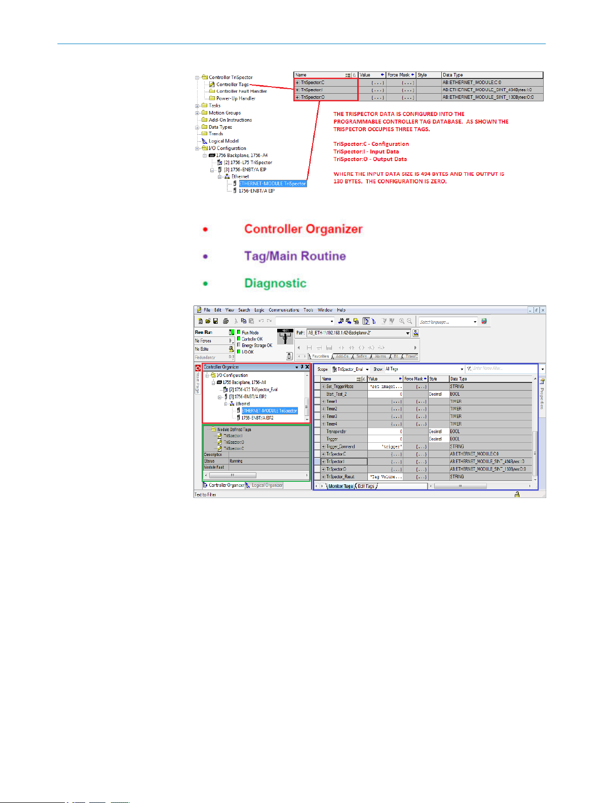
APPENDIX 12
The programmable controller’s software is defaulted into three windows.
In the ‘Controller Organizer’ window under ‘I/O Configuration’ if a device is selected its
current status will be displayed in the ‘Diagnostic’ window. The Names of the Tags data
generated from the device is shown, the Description of the device, the device Status,
and Module Fault(s).
Where:
Names of the Tags – are Input, Output, and Configuration data the device generates.
Description – user description of the device (this is entered during module setup).
Status – the current condition of the module. Could be ‘Running’, ‘I/O Fault’, ‘Con‐
necting’, ‘Shutting Down’, etc.
Module Fault – shows the fault code as well as a description of what the controller
is attempting to do to correct the problem.
In the ‘I/O Configuration’ if a device is selected and ‘Right Clicked’ a menu will pro‐
vide access to the device’s properties.
8021808/12ID/2019-01 | SICK O PE R AT I NG IN S TR U CT I ON S | TriSpector1000
Subject to change without notice
79

12 APPENDIX
In the properties window for the selected device, ‘General’ module configuration is
available
…as well as ‘Module Info’.
This window provides the current status of the module showing Faults, Hardware
Revision, Serial Number, and Product Name.
12.5.4 Triggering a TriSpector1000
To trigger the TriSpector1000 over EtherNet/IP a “trigger” command is used. The
TriSpector1000 is configured using SOPAS to receive its trigger by way of a command.
In the Image workflow step, configure the ‘Image trigger’ as shown.
80
O PE R AT I NG IN S TR U CT I ON S | TriSpector1000 8021808/12ID/2019-01 | SICK
Subject to change without notice

APPENDIX
12
With the TriSpector1000 configured to receive its trigger from the ‘Command Channel’,
the programmable controller can then be set up to write the ‘trigger’ command into the
‘Command channel string’ of the Output Tag Database.
This logic will ‘Copy’ the content of the User Defined Tag (UDT)
To the ‘Command channel string’.
The results will appear within the ‘Result string’ in the Input Tag Database.
8021808/12ID/2019-01 | SICK O PE R AT I NG IN S TR U CT I ON S | TriSpector1000
Subject to change without notice
81
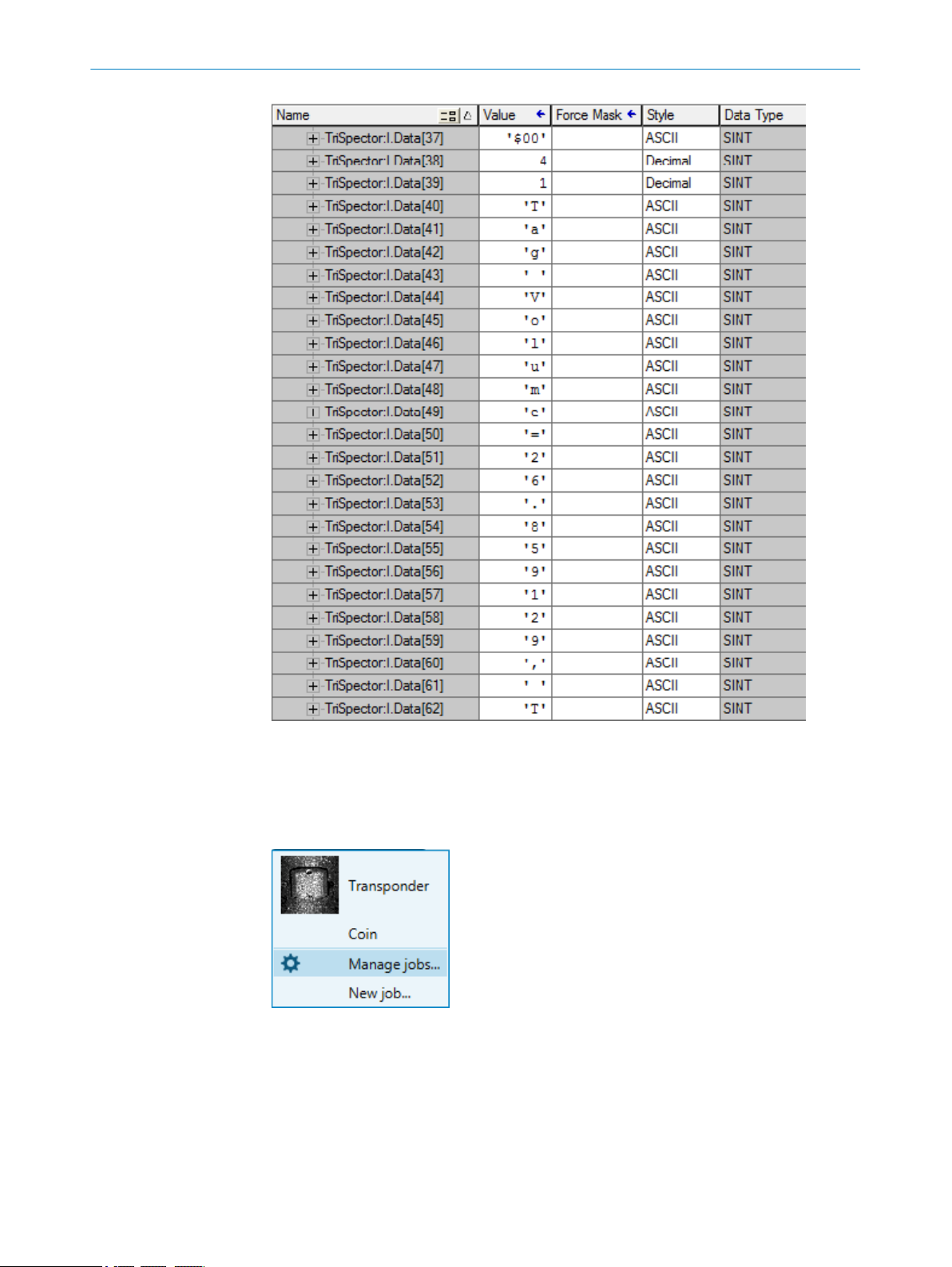
12 APPENDIX
12.5.5 Switching Jobs
The TriSpector1000 is capable of storing up to 32 jobs. These jobs can be selected
through the EtherNet/IP connection by way of a command.
Jobs can be added to the TriSpector1000 through SOPAS using ‘Manage jobs…’.
Once jobs are added to the TriSpector1000, instructions to the programmable con‐
troller can be used to switch jobs in the TriSpector1000.
The command used to switch jobs is ‘set job’. To select the correct job to switch to, the
name of the job can also be used.
In this example there are two jobs in the TriSpector 1000: “Transponder” and “Coin”. To
switch jobs in the TriSpector1000 there will need to be two commands and for each
command there will need to be two UDTs created in the programmable controller.
82
O PE R AT I NG IN S TR U CT I ON S | TriSpector1000 8021808/12ID/2019-01 | SICK
Subject to change without notice

The logic to execute the job switch is the same as the trigger.
To select the job named “Coin”.
APPENDIX
12
To select the job named “Transponder”.
When the command to select the job named “Coin” is sent from the programmable
controller to the TriSpector1000 by way of the ‘Command channel string’.
8021808/12ID/2019-01 | SICK O PE R AT I NG IN S TR U CT I ON S | TriSpector1000
Subject to change without notice
83

12 APPENDIX
A successful response will be available in the ‘Command response string’.
12.5.6 TriSpector1000 EtherNet/IP Compatibility
Table 22: Programmable Automation Controllers
RA Bulletin Number Product Interface
1769 CompactLogix Controllers, 1769-L2 and
1769-L3 Series
1768 CompactLogix Controllers, 1768-L4
Series
1756 ControlLogix, 1756-L6 Series 1756-EN2T Interface
1789 SoftLogix 5800 Controller Computer NIC
Built-in EtherNet/IP Port
1768-ENBT Scanner
1756-EN2F Interface
1756-ENBT Interface
84
Currently these controllers and the associated interface will provide EtherNet/IP net‐
work capabilities.
Online information on Rockwell Automation Programmable Logic Controllers, network
interfaces, and software can be found at www.rockwellautomation.com.
O PE R AT I NG IN S TR U CT I ON S | TriSpector1000 8021808/12ID/2019-01 | SICK
Subject to change without notice

12.6 TriSpector1000 Result Output Function Block
A guide for connecting your TriSpector1000 to a Siemens PLC
This operating instruction will guide you through the process of connecting the TriSpec‐
tor1000 to the PLC, using the TriSpector1000 function block to parse an example string
and finally how to modify the function block to suit your needs.
12.6.1 About this document
Please read this chapter carefully before working with this documentation and the
TriSpector1000 Result Output function block.
12.6.1.1 Purpose of this document
This operating instruction will guide you through the process of connecting the TriSpec‐
tor1000 to the PLC, using the TriSpector1000 function block to parse an example string
and finally how to modify the function block to suit your needs.
NOTE
This document does not provide a plug-and-play solution that will fit any result output
string. This document is a guide how to set up the PLC for a specific example output
string from the TriSpector1000. This document will also guide you how to modify the
function block by editing the structured text implementation of the function block.
APPENDIX 12
12.6.1.2 Target group
This operating instruction addresses planning engineers, developers and operators of
machines and systems who use a TriSpector1000 vision sensor and who are familiar
with S7 PLC programming using the TIA-Portal.
12.6.1.3 Scope
This document applies to the following variants of TriSpector1000:
■
■
■
12.6.1.4 Supported PLCs
The function blocks can be downloaded from the SICK Support Portal:
1. Log on to the SICK Support Portal.
2. Under the Vision tab, click TriSpector1000 and navigate to the TriSpector PLC function
3. Click on Zip to start the function blocks to start the download.
The zip folder contains function blocks for the following controllers:
■
■
■
■
TriSpector1008
TriSpector1030
TriSpector1060
blocks for Siemens S7 page.
S7-300
S7-400
S7-1200
S7-1500
The table below tells you what function block to choose depending on your PLC version.
It is important that you choose the correct function block corresponding to your PLC ver‐
sion. The function blocks are different and not compatible with each other. The differ‐
ences are explained in more detail in chapter 12.6.7.
8021808/12ID/2019-01 | SICK O PE R AT I NG IN S TR U CT I ON S | TriSpector1000
Subject to change without notice
85

12 APPENDIX
12.6.2 Overview
Folder name Compatible with Siemens S7 version
Siemens S7-1500,1200 S7-1500 and S7-1200 firmware version 4.x
Siemens S7-1200 S7-1200 firmware version > 2 and < 4
Siemens
S7-300,400,1200
S7-300, S7-400 and S7-1200 firmware version 1.x
NOTE
You need to use the TIA-Portal to be able to use those function blocks. If you use the old
SIMATIC STEP7 V5.5 software it is not possible to use those function blocks.
The Result Output function block simplifies the use of a TriSpector1000 vision sensor
on Simatic S7-1500/1200/400/300 controls. It is designed for TCP/IP communica‐
tion. The function block supports the task to read and normalize an example output
string from the TriSpector1000.
The picture below shows the concept behind the TriSpector1000 PLC integration.
12.6.3 TriSpector1000 configuration
To integrate the TriSpector1000 into the TIA PLC environment, the current active Result
Output configuration must be known in the PLC program. This function block is written
to handle a specific example string. To follow this example this string need to be config‐
ured in the TriSpector1000.
12.6.3.1 Define output string
The user can define the TriSpector1000 Ethernet output string in any way she wants, it
can be short, it can be long, it can contain only numbers, it can contain only characters,
it’s up to the user to decide. This function block can’t handle any type of result string.
86
O PE R AT I NG IN S TR U CT I ON S | TriSpector1000 8021808/12ID/2019-01 | SICK
Subject to change without notice
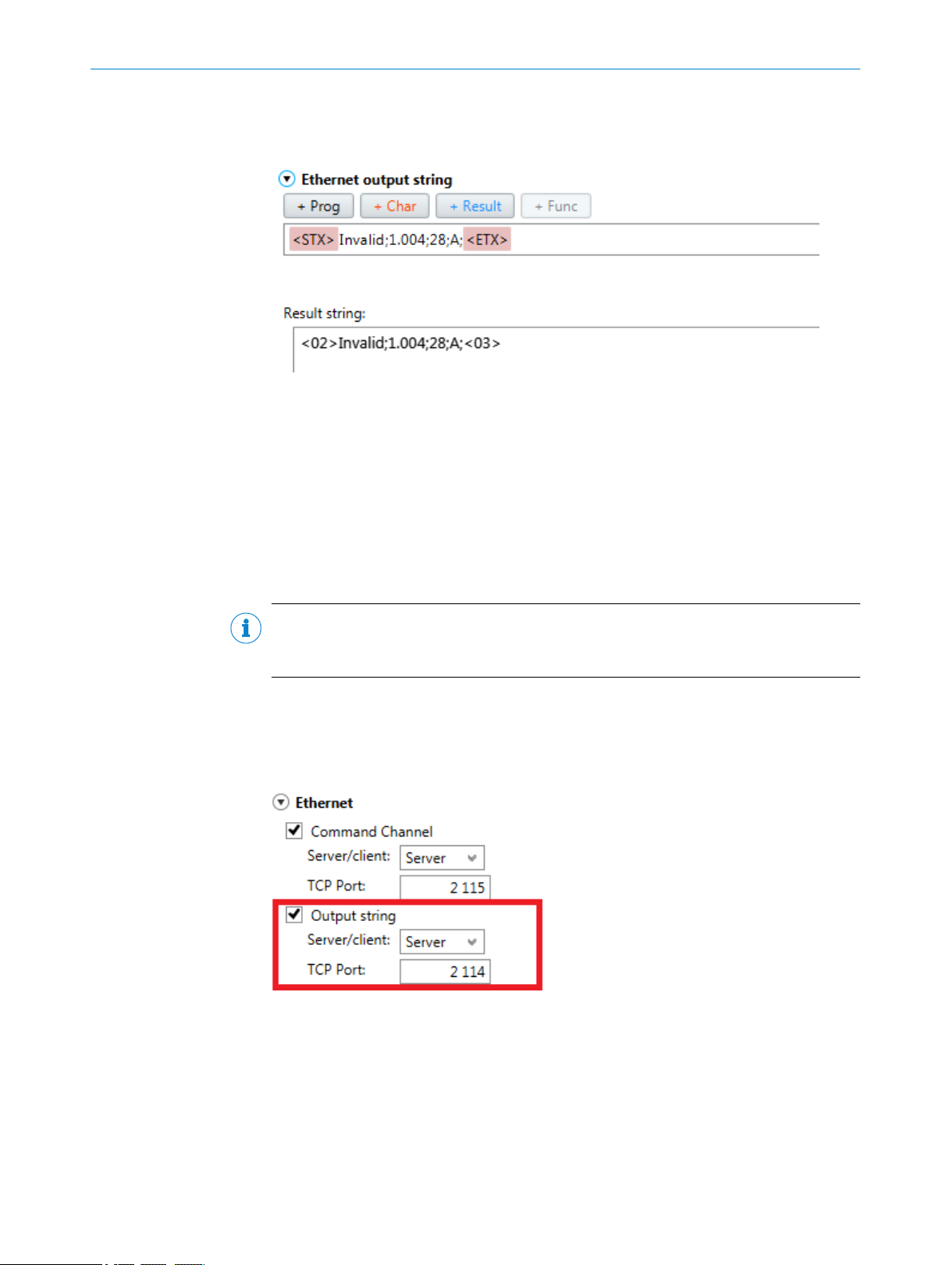
APPENDIX 12
This function block will only handle an example of a result string. It is up to the PLC pro‐
grammer to make changes in the function block to make it work with the current out‐
put.
The result string in the image above is what we use as an example string for this func‐
tion block. This string contains a string, a real number, an integer and a character. In
the TriSpector1000 this corresponds to different data types but when sent over TCP/IP
it will all be sent as a string. No other data types will be transmitted. Thus in the exam‐
ple above the numeric value 1.004 will be a string of 5 characters that needs to be
parsed and converted to a real by the function block in the PLC. To know when a value
starts and stops a delimiter is used; in the example above we use a semicolon between
every value. The string needs to start with a <STX> character and end with a <ETX> char‐
acter.
NOTE
To be able to use this function block be sure to configure this output string in the
TriSpector1000.
12.6.3.2 Enable output string over TCP
Make sure that the output string is enabled on Ethernet. In SOPAS go to the Interfaces
tab -> Ethernet section. Enable Output string, choose to act as server on default TCP port
2114.
12.6.4 PLC Configuration
12.6.4.1 Establish a TCP connection
The TriSpector1000 Result Output function block uses a TCP connection between the
sensor and the S7 PLC to get the result output data. The TCP communication must be
established by using the Siemens function block “TCON”.
8021808/12ID/2019-01 | SICK O PE R AT I NG IN S TR U CT I ON S | TriSpector1000
Subject to change without notice
87

12
APPENDIX
Use the Siemens TCON function block
To establish an open TCP connection the following communication blocks are available
in the Siemens standard library (Communication -> Open user communication -> Others):
■
“TCON” for establishing the connection
■
“TDISCON” for terminating the connection
■
“T_CONFIG” to configure the interface
In this example the “TCON” (see image below) is called in OB1 with the instance data
block “TCON_DB”. In the case of a reboot, the “#Initial_Call” flag triggers the TCON FB
to open the TCP communication. The ID of the TriSpector1000 FB Input must have the
same value as the ID input of the TCON FB (will be set up in next step).
The connection parameters (input parameter “CONNECT”) for setting up the TCP con‐
nection are stored in an automatically generated data block. Please open the “Proper‐
ties” of the TCON FB to make the settings and generate the data block.
88
O PE R AT I NG IN S TR U CT I ON S | TriSpector1000 8021808/12ID/2019-01 | SICK
Subject to change without notice

For more information see the TIA Portal help system.
12.6.4.2 Import the TriSpector1000 Test Function Block
To get the generated blocks into your PLC project, the “TrispectorTest_FB.scl” file must be
imported as an external source file (“Add new external file”).
APPENDIX
12
To use the block, it is necessary to generate it first from the source file. Right mouse
click on the SCL-File -> Generate blocks from source.
8021808/12ID/2019-01 | SICK O PE R AT I NG IN S TR U CT I ON S | TriSpector1000
Subject to change without notice
89
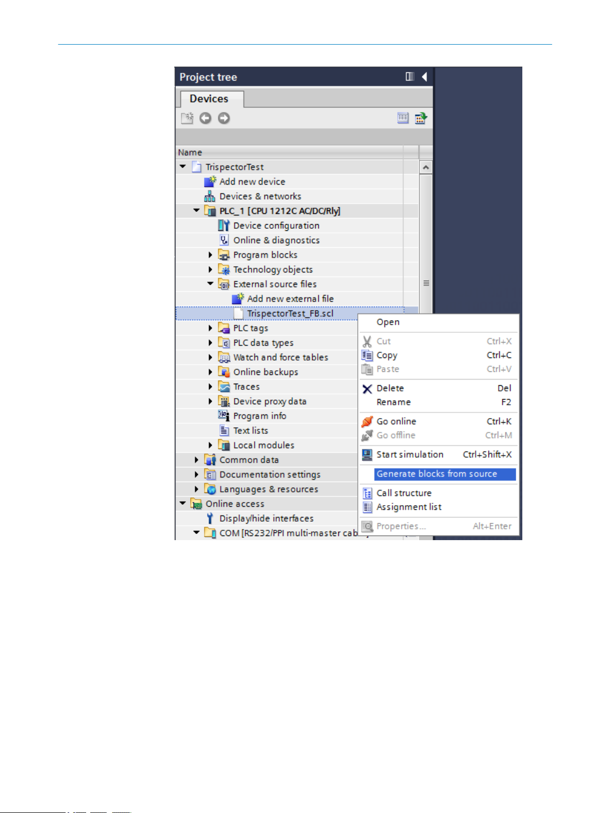
12
APPENDIX
90
Now the TIA Portal automatically generates the PLC blocks and adds it to your program.
After successful generation, the blocks are created in the “Program blocks” and in the
“PLC data types” folder in the TIA project tree.
O PE R AT I NG IN S TR U CT I ON S | TriSpector1000 8021808/12ID/2019-01 | SICK
Subject to change without notice

APPENDIX 12
NOTICE
If a PLC block with the same name as the generated block located in the project exists,
the existing block will be overwritten.
12.6.4.3 Function block usage
The picture below shows the generated function block which can interpret an incoming
string with format string;real;integer;character; for example “Invalid;1.004;28;A;” from the
TriSpector1000.
Function block parameters
Parameter Declaration Data type Description
ID Input CONN_OUC TCP Connection ID
getting from the TCON
Function Block
8021808/12ID/2019-01 | SICK O PE R AT I NG IN S TR U CT I ON S | TriSpector1000
Subject to change without notice
91

12
APPENDIX
Parameter Declaration Data type Description
Data Input UDT (generated data
type)
Done Output BOOL The rising edge indi‐
Error Output BOOL Error flag
Errorcode Output DWORD Error code, see error
Reference to the gen‐
erated data structure
instance
cates that new data is
available
FALSE: no new data
available
TRUE: new data avail‐
able
FALSE: no error
detected
TRUE: error detected
description in
chapter 12.6.6.2
The ID must be the same as the ID parameter of the TCON FB. The Data Parameter
needs a reference to the data structure instance. You create this reference by adding a
data block that contains a variable of data type Trispector_Test_Input. Here this block is
called DB_Trispector_Data and contains a variable called Trispector_Data. The data block is
created by double-click on “Add new block”.
92
In the block added you create a variable Trispector_Data that is of type Trispec‐
tor_Test_Input.
Use the variable created as the Data input parameter to the function block. Now you
should have two networks looking like in the image below.
O PE R AT I NG IN S TR U CT I ON S | TriSpector1000 8021808/12ID/2019-01 | SICK
Subject to change without notice
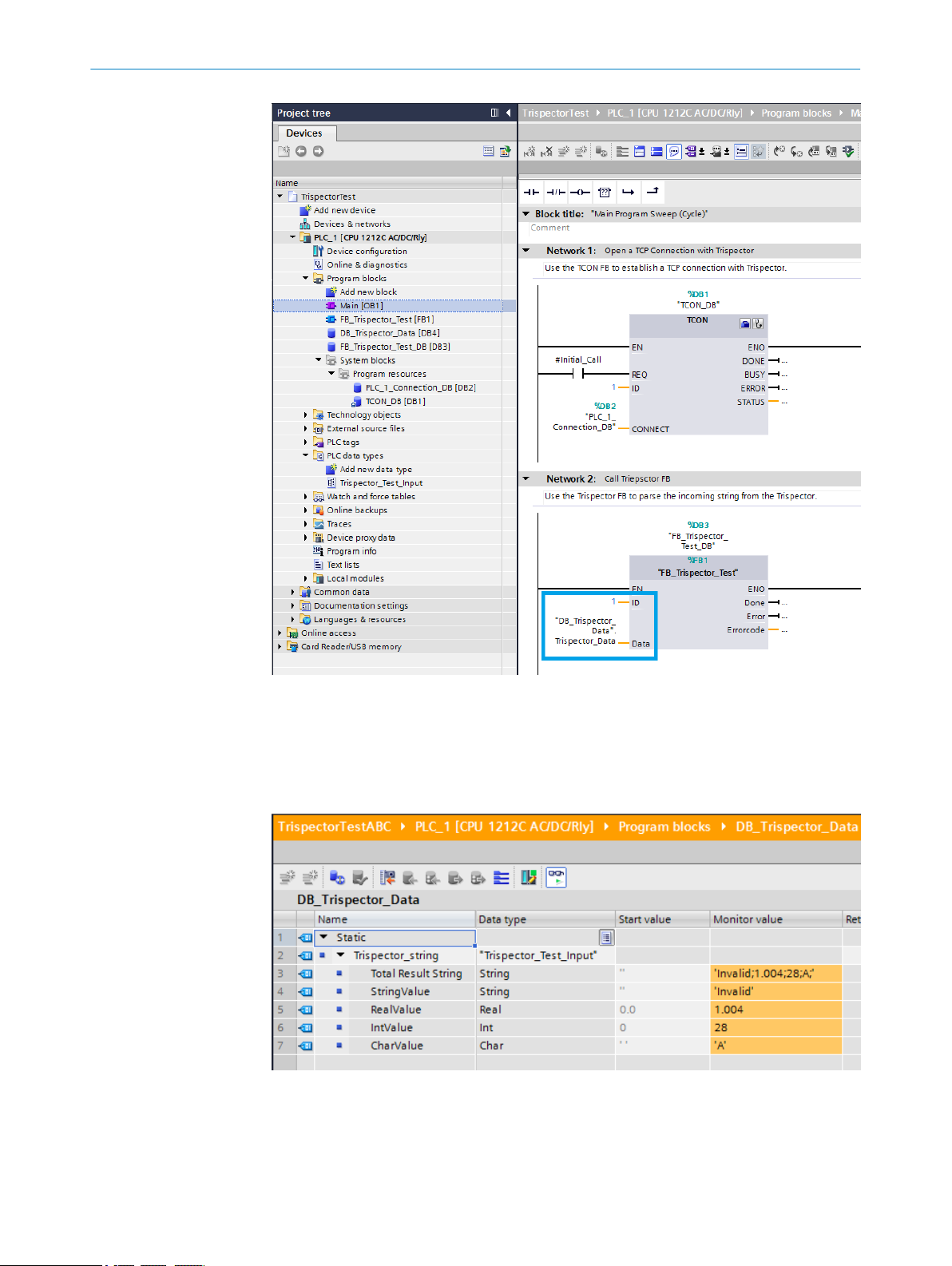
APPENDIX 12
12.6.4.4 Observing the inspection results
When the configuration has been activated and the PLC is in “RUN” mode, the inspec‐
tion results can be observed in the instance DB of the generated structure, in this case
DB_Trispector_Data. The structure is updated each time when the inspector sends new
data (Done flag).
8021808/12ID/2019-01 | SICK O PE R AT I NG IN S TR U CT I ON S | TriSpector1000
Subject to change without notice
93
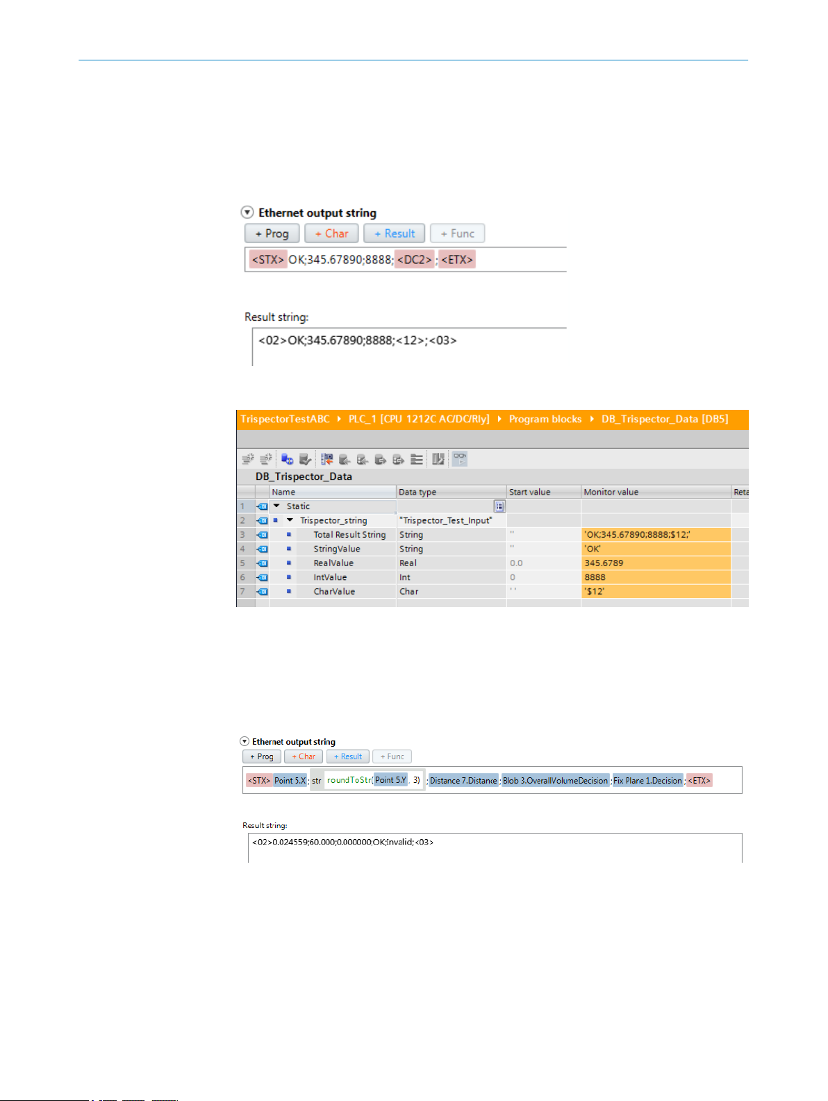
12 APPENDIX
12.6.5 Modify the Function Block to fit your output
12.6.5.1 Modify the example string
The example we have used is for parsing a string with four variables: string;real;int;char;.
They do not need to have the values we have tested, try to modify the values but still
keeping the data types and see that it is still working. For example:
Now you should see those values in your DB_Trispector_Data.
12.6.5.2 Use your desired output string
Probably you want to send some other data in your result output from the TriSpec‐
tor1000. You need to configure the function block and the data type (UDT) to fit your
desired result. An example of how that is done is described below.
Imagine you want to use the following output string from the TriSpector1000.
In the output string above there are 3 real values followed by 2 string values. The UDT
needs to be modified to match this.
We will use this “new” string in the following examples to show how to modify your UDT
and FB.
94
O PE R AT I NG IN S TR U CT I ON S | TriSpector1000 8021808/12ID/2019-01 | SICK
Subject to change without notice
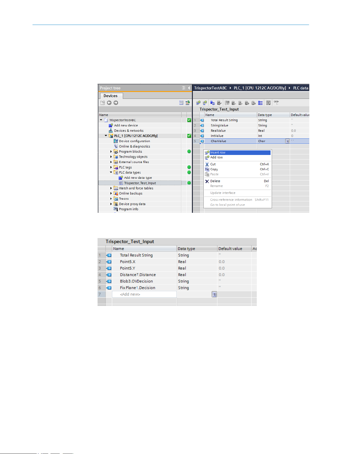
12.6.5.3 Modify your UDT
The UDT (User Defined Datatype) in this example is Trispector_Test_Input. It is found in
PLC data types folder. By right clicking in the UDT view you can insert rows and delete
rows. Make the UDT match your current output. It is a good idea to keep the Total Result
String variable for debugging purpose, if you want to remove it later that is fine and it will
save you some processing time. How this is done is described in chapter 12.6.5.4.1.
APPENDIX
12
If we use the new example string defined in section 6.2 the UDT should look something
like this.
After changing the UDT you need to compile the Data Block using this UDT that is
DB_Trispector_Data. Right mouse click on data block DB_Trispector_Data -> Compile -> Soft‐
ware (only changes).
8021808/12ID/2019-01 | SICK O PE R AT I NG IN S TR U CT I ON S | TriSpector1000
Subject to change without notice
95

12
APPENDIX
12.6.5.4 Modify the Function Block
Secondly you need to modify the function block FB_Trispector_Test to parse the incoming
data correct. Open the function block and scroll down to the comment:
//********************START THE PARSING*********************
This is where the parsing of the string into different data types starts. Since the func‐
tion block expects four values (string;real;int;char) this parsing is divided into four sec‐
tions:
//1: String of unknown size
************************************************************
WHILE (BYTE_TO_CHAR(#arrData[#i]) <> ';' & #i <>
(#iReceivedLength-1)) DO
#s_temp := CONCAT(IN1 := #s_temp, IN2 :=
CHAR_TO_STRING(BYTE_TO_CHAR(#arrData[#i])));
#i := #i + 1;
END_WHILE;
#Data.StringValue := #s_temp;
#s_temp := '';
#i := #i + 1;
//**********************************************************
//2: Real of unknown size
************************************************************
WHILE (BYTE_TO_CHAR(#arrData[#i]) <> ';' & #i <>
(#iReceivedLength-1)) DO
#s_temp := CONCAT(IN1 := #s_temp, IN2 :=
CHAR_TO_STRING(BYTE_TO_CHAR(#arrData[#i])));
#i := #i + 1;
END_WHILE;
#Data.RealValue := STRING_TO_REAL(#s_temp);
#s_temp := '';
#i := #i + 1;
//**********************************************************
96
//3: Int of unknown size
O PE R AT I NG IN S TR U CT I ON S | TriSpector1000 8021808/12ID/2019-01 | SICK
Subject to change without notice

APPENDIX
************************************************************
WHILE (BYTE_TO_CHAR(#arrData[#i]) <> ';' & #i <>
(#iReceivedLength-1)) DO
#s_temp := CONCAT(IN1 := #s_temp, IN2 :=
CHAR_TO_STRING(BYTE_TO_CHAR(#arrData[#i])));
#i := #i + 1;
END_WHILE;
#Data.IntValue := STRING_TO_INT(#s_temp);
#s_temp := '';
#i := #i + 1;
//**********************************************************
//4: Char of known size 1 byte
************************************************************
#Data.CharValue := BYTE_TO_CHAR(#arrData[#i]);
//**********************************************************
12
Those four sections are possible to copy and paste and combine in any way suited for
your needs to match your output string as long as the data types are strings, integers,
real values or characters. If you want to parse any other data types you need to figure it
out yourself but if you stick to those data types you can combine the sections to parse
any output string where the number of variables is known.
NOTE
If your output string contains an unknown number of variables, it might be depending
on how many blobs found for example, this approach will not work. You need to rewrite
the code block.
Since we now have a UDT with 3 real values followed by 2 string values this code need
to be modified to fit this. For the real values reuse section 2; Real of unknown size. For
the string values reuse section 1; String of unknown size.
Remove all of the code above and insert three section 2 snippets followed by two sec‐
tion 1 snippets. Finally you need to assign the parsed values to the correct name in the
UDT since this has changed (see the Data variables in the code below). The result
should look like this:
//1: Real of unknown size
************************************************************
WHILE (BYTE_TO_CHAR(#arrData[#i]) <> ';' & #i <>
(#iReceivedLength-1)) DO
#s_temp := CONCAT(IN1 := #s_temp, IN2 :=
CHAR_TO_STRING(BYTE_TO_CHAR(#arrData[#i])));
#i := #i + 1;
END_WHILE;
#Data."Point5.X" := STRING_TO_REAL(#s_temp);
#s_temp := '';
#i := #i + 1;
//**********************************************************
//2: Real of unknown size
************************************************************
WHILE (BYTE_TO_CHAR(#arrData[#i]) <> ';' & #i <>
(#iReceivedLength-1)) DO
#s_temp := CONCAT(IN1 := #s_temp, IN2 :=
CHAR_TO_STRING(BYTE_TO_CHAR(#arrData[#i])));
#i := #i + 1;
END_WHILE;
#Data."Point5.Y" := STRING_TO_REAL(#s_temp);
#s_temp := '';
8021808/12ID/2019-01 | SICK O PE R AT I NG IN S TR U CT I ON S | TriSpector1000
Subject to change without notice
97

12
APPENDIX
#i := #i + 1;
//**********************************************************
//3: Real of unknown size
************************************************************
WHILE (BYTE_TO_CHAR(#arrData[#i]) <> ';' & #i <>
(#iReceivedLength-1)) DO
#s_temp := CONCAT(IN1 := #s_temp, IN2 :=
CHAR_TO_STRING(BYTE_TO_CHAR(#arrData[#i])));
#i := #i + 1;
END_WHILE;
#Data."Distance7.Distance" := STRING_TO_REAL(#s_temp);
#s_temp := '';
#i := #i + 1;
//**********************************************************
//4: String of unknown size
*************************************************************
WHILE (BYTE_TO_CHAR(#arrData[#i]) <> ';' & #i <>
(#iReceivedLength-1)) DO
#s_temp := CONCAT(IN1 := #s_temp, IN2 :=
CHAR_TO_STRING(BYTE_TO_CHAR(#arrData[#i])));
#i := #i + 1;
END_WHILE;
#Data."Blob3.OVDecision" := #s_temp;
#s_temp := '';
#i := #i + 1;
//**********************************************************
//5: String of unknown size
*************************************************************
WHILE (BYTE_TO_CHAR(#arrData[#i]) <> ';' & #i <>
(#iReceivedLength-1)) DO
#s_temp := CONCAT(IN1 := #s_temp, IN2 :=
CHAR_TO_STRING(BYTE_TO_CHAR(#arrData[#i])));
#i := #i + 1;
END_WHILE;
#Data."Fix Plane1.Decision" := #s_temp;
#s_temp := '';
#i := #i + 1;
//**********************************************************
Now compile and have a look at the inspection result.
98
O PE R AT I NG IN S TR U CT I ON S | TriSpector1000 8021808/12ID/2019-01 | SICK
Subject to change without notice

12.6.5.4.1 Remove Total Result String
Finally if you do not want the total string anymore (Total Result String), this is mostly used
for debug purposes, you could simply remove it. Remove it from your UDT and find the
code snippet below in the function block and delete this snippet. It loops through the
whole string, waiting for the <ETX> character that determines the end of the string.
Since the string is looped through once again to parse all the variables it is a good idea
to remove this snippet if the time is critical.
//While we don't have <ETX>, save bytes to result string
//Saving the total result string is mostly for testing, this could
be removed to save time!
WHILE (BYTE_TO_CHAR(#arrData[#i]) <> '$03') DO
//Save every byte to the total result string
#s_total := CONCAT(IN1 := #s_total, IN2 :=
CHAR_TO_STRING(BYTE_TO_CHAR(#arrData[#i])));
#i := #i + 1;
END_WHILE;
#Data."Total Result String" := #s_total
//Start over and loop through incoming data again to cast every
single data type sent
#i := 6;
APPENDIX
12
12.6.5.5 Increase the data array size
In the current function block the data received from the TriSpector1000 is saved in an
array of 100 bytes. If the string sent from the TriSpector1000 contains more than 100
bytes (characters) you need to extend this array. This is done by editing the data type in
the function block FB_Trispector_Test, shown in the image below.
After changing the size of the array you need to compile the data block corresponding to
this function block to get it updated as well. Right mouse click on the data block
FB_Trispector_Test_DB -> Compile -> Software (only changes).
8021808/12ID/2019-01 | SICK O PE R AT I NG IN S TR U CT I ON S | TriSpector1000
Subject to change without notice
99

12 APPENDIX
12.6.6 Troubleshooting
12.6.6.1 No data appears
If no data appears it might be that the string you are sending are too long. If it is more
than 100 characters you need to increase the data array size, see chapter 6.5.
It could also be that you are missing the <STX> and the <ETX> characters at start and
end of string, those are needed for the PLC to retrieve the string.
12.6.6.2 Error codes
If none of the problems above, have a look at the monitored values in FB_Trispec‐
tor_Test_DB, the Errorcode might tell you what the problem is.
100
O PE R AT I NG IN S TR U CT I ON S | TriSpector1000 8021808/12ID/2019-01 | SICK
Subject to change without notice
 Loading...