

Page 1
I
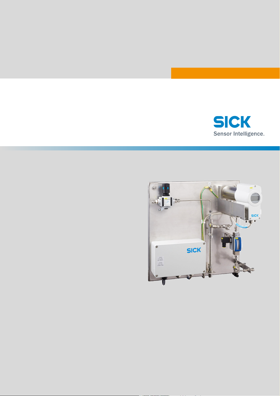
TRANSIC Extractive
MMMOPERATING INSTRUCTIONS
OPERATING INSTRUCTIONS
MMM
Page 2

Beschriebenes Produkt
Produktname: TRANSIC Extractive
Dokument ID.: 8021262
Manufacturer
SICK AG
Erwin-Sick-Str. 1 · 79183 Waldkirch · Germany
Telefon: +49 7641 469-0
Fax: +49 7641 469-1149
E-Mail: info.pa@sick.de
Production location
SICK AG
Nimburger Str. 11 · 79276 Reute · Germany
Legal information
This work is protected by copyright. Any rights derived from the copyright shall be
reserved for SICK AG. Reproduction of this document or parts of this document is only
permissible within the limits of the legal determination of Copyright Law. Any modification, expurgation or translation of this document is prohibited without the express written permission of SICK AG.
The trademarks stated in this document are the property of their respective owner.
© SICK AG. All rights reserved
Original document
This document is an original document of SICK AG.
2
8021262/V1-0/2017-04| SICKOPERATING INSTRUCTIONS | TRANSIC Extractive
Subject to change without notice
Page 3

Content
CONTENT
1 About this Document ................................................................................ 5
1.1 Limitation of Liability....................................................................................... 5
1.2 Purpose of this Document .............................................................................. 5
1.3 Target Group.................................................................................................... 5
1.4 Further Information ......................................................................................... 5
1.5 Additional Technical Documentation ............................................................. 6
1.6 Document Conventions................................................................................... 6
2 Important Safety Instructions .................................................................. 7
2.1 Supplemental Directives................................................................................. 7
2.2 Safety Conventions ......................................................................................... 7
2.3 Warning Signs ................................................................................................. 8
2.4 Mandatory symbols conventions.................................................................... 8
2.5 Safety Messages .............................................................................................8
2.6 Notices............................................................................................................. 9
2.7 Intended Use .................................................................................................10
2.7.1 RoHS Directive ..............................................................................10
2.7.2 Measured components.................................................................10
2.7.3 Measuring range...........................................................................10
2.8 Requirements for the Qualification of Personnel ........................................10
3 System Description .................................................................................11
3.1 Characteristics ..............................................................................................11
3.2 Gas Flow Diagram .........................................................................................12
3.3 Method of Operation .....................................................................................13
3.3.1 Settings .........................................................................................13
4 Installation ................................................................................................15
4.1 Mounting Plate ..............................................................................................15
5 Operation ..................................................................................................17
5.1 Interfaces ......................................................................................................17
5.1.1 Keypad ..........................................................................................17
5.2 Maintenance Interface..................................................................................18
6 Maintenance............................................................................................. 19
7 Technical Data .........................................................................................21
8 Disposal..................................................................................................... 23
8021262/V1-0/2017-04| SICK OPERATING INSTRUCTIONS | TRANSIC Extractive
Subject to change without notice
3
Page 4

CONTENT
4
8021262/V1-0/2017-04| SICKOPERATING INSTRUCTIONS | TRANSIC Extractive
Subject to change without notice
Page 5

1About this Document
Note
This document regarding the TRANSIC Extractive:
● Contains information required during the life cycle of the System.
● Is available to all those people who work with the System.
Please read this document carefully and make sure that you understand the
content fully before working with the System.
1.1 Limitation of Liability
Note
Applicable standards and regulations, the latest state of technological development and many years of knowledge and experience have all been taken into
account, when assembling the data and information contained in this document.
The manufacturer accepts no liability for damage caused by:
● Failing to observe this document.
● Non-compliance of notices and regulations.
● Unauthorized installation and mounting of the TRANSIC Extractive.
● Arbitrary modifications.
● Use of unauthorized spare parts, consumables and accessories.
With special variants, where optional extras have been ordered, or owing to the
latest technical changes, the actual scope of delivery may vary from the features and illustrations shown here.
ABOUT THIS DOCUMENT 1
1.2 Purpose of this Document
This document describes the TRANSIC Extractive.
1.3 Target Group
This document is intended for qualified personnel which are authorized to perform installation, operation, and maintenance on the TRANSIC Extractive.
1.4 Further Information
Special local conditions
Follow all local laws, technical rules, and company-internal operating directives applicable
at the respective installation site of the TRANSIC Extractive.
Preserving the documents
This document and the additional technical documentation and information must be:
● Available for reference
● Passed on to new owners
8021262/V1-0/2015-09| SICK AG OPERATING INSTRUCTIONS | TRANSIC Extractive
Subject to change without notice
5
Page 6
1 ABOUT THIS DOCUMENT
1.5 Additional Technical Documentation
● Operating instructions of the following system components:
Component Manufacturer
OI_TRANSIC151LP
● Technical System-Documentation (EPLAN) contains:
–Technical Data
–Wiring diagram
–Gas flow diagram
1.6 Document Conventions
▸ Instruction
Refer to another document.
All units of measurement in this document are originally metric units.
Subject to change without notice. Images might differ from actual design.
SICK
6
8021262/V1-0/2015-09| SICKOPERATING INSTRUCTIONS | TRANSIC Extractive
Subject to change without notice
Page 7

2Important Safety Instructions
Note
Read and follow all safety instructions in this document.
2.1 Supplemental Directives
WARNING
▸ Read and understand this document carefully prior to working on the
system or any other of its components.
▸ Only fully trained professionals from the respective field are permit-
ted to work on the system.
▸ Follow all operational procedures.
▸ Follow all local regulations.
▸ Follow all local regulations regarding working with gas and electrical
components.
▸ Entry to system area is only permitted to authorized personnel.
▸ Wear personal protective equipment (PPE) while on the system area.
IMPORTANT SAFETY INSTRUCTIONS 2
2.2 Safety Conventions
Symbols on system and system components labels, safety labels and in safety messages
inside this document are according to the current standards.
The following conventions for signal words are used in this document, complying with
ANSI Z535.6:
NOTICE
NOTICE is used to address practices not related to personal injury but to property dam-
ages.
DANGER
DANGER indicates a hazardous situation with a high risk level, which if
not avoided, will result in death or serious injury.
WARNING
WARNING indicates a hazardous situation with a middle risk level,
which if not avoide d, could result in death or serious inju r y.
CAUTION
CAUTION indicates a potentially dangerous situation with a low risk
level, which if not avoided may lead to minor or moderates injuries.
Note
Indicates important information and useful hints.
8021262/V1-0/2017-04| SICK AG OPERATING INSTRUCTIONS | TRANSIC Extractive
Subject to change without notice
7
Page 8
2 IMPORTANT SAFETY INSTRUCTIONS
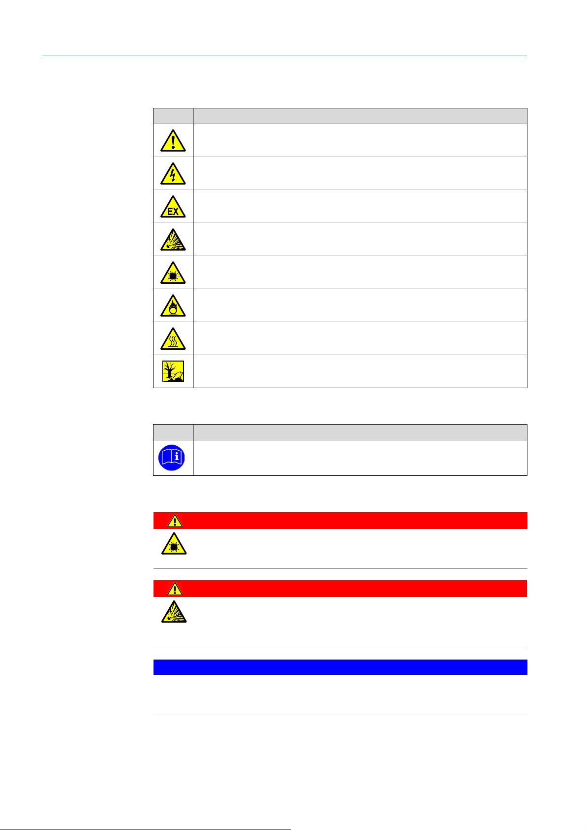
2.3 Warning Signs
Sign Significance
Hazard (general)
Hazard by voltage
Hazard in potentially explosive areas
Risk of explosion
Hazard by laser
Hazard by oxidizing substances
Hazard by hot surfaces
Hazard for the environment, nature and organic life
2.4 Mandatory symbols conventions
Symbol Significance
Refer to another document
2.5 Safety Messages
DANGER
LASER Protection Class 1
Hazard by laser. Serious injuries.
▸ Do not place reflective objects directly into the probe.
DANGER
RISK BY OXIDATION PROCESS
Death or serious injury will occur.
▸ Check ambient conditions before start installation and/or commis-
sioning.
NOTICE
ELECTROSTATIC CHARGE
Note the ESD regulations. Do not touch components inside the enclosure, these can be
damaged.
8
8021262/V1-0/2017-04| SICKOPERATING INSTRUCTIONS | TRANSIC Extractive
Subject to change without notice
Page 9

IMPORTANT SAFETY INSTRUCTIONS 2
DANGER
HAZARDOUS VOLTAGE
The system is supplied with mains voltage from the grid. Danger of
electrocution - contact will cause electric shock, burn or death.
▸ Only qualified personnel can perform electrical works on the system.
▸ Always exercise caution when handling cables and connectors.
▸ Before working on the system:
▸ Follow operational procedures such as Lockout-Tagout.
▸ Check that there is no residual voltage by measuring AC voltages.
WARNING
FLAMMABLE OR EXPLOSIVE GAS MIXTURE
Serious injuries.
▸ To avoid inflammable or explosive gas mixtures we recommend to
use only Nitrogen (N
) as propellant gas.
2
▸ If an inflammable or explosive gas mixtures can not be avoided
ensure proper treatment or disposal (exhaust) after sample gas outlet.
▸ If calibrating the TRANSIC151LP with ambient air, ensure proper
treatment or disposal (exhaust) after sample gas outlet.
2.6 Notices
NOTICE
SYSTEM WARRANTY
If you disregard the safety and hazard precautions, no warranty claim for damages will be
honored. If you alter parts of the System by your own initiative, all warranty claims will be
forfeited.
▸ Regard all safety and hazard precautions.
▸ Use only material supplied or approved by SICK for the system maintenance.
▸ Do not alter the system.
NOTICE
SYSTEM DAMAGE
Damage to any system components or parts can lead to malfunction of the entire System. Do not ignore damaged or broken parts, refer to this manual and contact SICK support immediately.
▸ Do not install damaged parts.
8021262/V1-0/2017-04| SICK AG OPERATING INSTRUCTIONS | TRANSIC Extractive
Subject to change without notice
9
Page 10

2 IMPORTANT SAFETY INSTRUCTIONS
2.7 Intended Use
The TRANSIC Extractive is a stationary system and serves continuous measurement of oxygen in the industrial sector.
The sample gas is taken from a sampling point and feed through the gas analyzer
(extractive measurement).
Operation in explosion-hazard areas
Suitable for areas according to ATEX and IECEx (IEC 60079-10).
For further and detailed information about intended use of the TRNSIC151LP,
refer to the respective Operating Instructions.
2.7.1 RoHS Directive
This product is designed for applications in large industrial plants according to
Article 2 (4) e, RoHS 2011/65/EU and can therefore only be used in such systems.
The product is neither suitable nor approved for use outside of theses systems.
SICK cannot assume any kind of warranty or liability for use outside of these systems.
2.7.2 Measured components
Gases O2 (Oxygen)
2.7.3 Measuring range
Component Range Unit
O
2
0 ... 21 %
0 ... 100 %
ambient measurement 2 ... 21 %
2.8 Requirements for the Qualification of Personnel
Note
Qualified personnel
● Qualified personnel have the specialist training, skills, and experience, as
well as knowledge of the relevant regulations and standards, to be able to
perform tasks delegated to them and to detect and to avoid any potential
dangers independently.
● Electricians have the specialist training, skills, and experience, as well as
knowledge of the relevant standards and provisions to be able to carry out
work on electrical systems and to detect and avoid any potential dangers
independently.
10
8021262/V1-0/2017-04| SICKOPERATING INSTRUCTIONS | TRANSIC Extractive
Subject to change without notice
Page 11

3 System Description
3.1 Characteristics
The TRANSIC Extractive is an analysis system to measure and monitor oxygen.
The TRANSIC Extractive works extractive, i.e. the gas to be measured is taken from the gas
duct using a gas extraction probe or probes and fed to the analysis system via sample gas
line(s).
SYSTEM DESCRIPTION 3
Fig. 1: TRANSIC Extractive system components
Legend
TRANSIC151LP
1
2
Needle valve
3
Flow meter
4
Manual valve sample gas/reference gas
5
Sample and propellant gas outlet
6
Voltage supply unit
7
Injector pump
8
Propellant gas inlet
9
Pressure reducer
10
Grounding point
8021262/V1-0/2017-04| SICK AG OPERATING INSTRUCTIONS | TRANSIC Extractive
Subject to change without notice
11
Page 12

3 SYSTEM DESCRIPTION
3.2 Gas Flow Diagram
12
Fig. 2: TRANSIC Extractive gas flow diagram
8021262/V1-0/2017-04| SICKOPERATING INSTRUCTIONS | TRANSIC Extractive
Subject to change without notice
Page 13

3.3 Method of Operation
The sample gas is fed through gas analyzer and flow meter via injector pump. The sample
gas and the propellant gas are mixed in the injector pump. This gas mixture is fed to the
sample gas outlet.
3.3.1 Settings
The sample flow rate can be adjusted via needle valve and/or propellant gas pressure
reducer:
▸ Needle valve open - higher sample gas flow.
▸ Needle valve close - lower sample gas flow.
▸ Higher propellant gas pressure - higher sample gas flow.
▸ Lower propellant gas pressure - lower sample gas flow.
▸ For calibration with ambient air or reference gases sample gas inlet can be switched via
manual valve.
SYSTEM DESCRIPTION 3
WARNING
FLAMMABLE OR EXPLOSIVE GAS MIXTURE
Serious injuries.
▸ To avoid inflammable or explosive gas mixtures we recommend to
use only Nitrogen (N
) as propellant gas.
2
▸ If an inflammable or explosive gas mixtures can not be avoided
ensure proper treatment or disposal (exhaust) after sample gas outlet.
▸ If calibrating the TRANSIC151LP with ambient air, ensure proper
treatment or disposal (exhaust) after sample gas outlet.
For further and detailed information about calibration of the TRANSIC151LP,
refer to the respective Operating Instructions.
8021262/V1-0/2017-04| SICK AG OPERATING INSTRUCTIONS | TRANSIC Extractive
Subject to change without notice
13
Page 14

3 SYSTEM DESCRIPTION
14
8021262/V1-0/2017-04| SICKOPERATING INSTRUCTIONS | TRANSIC Extractive
Subject to change without notice
Page 15

4 Installation
4.1 Mounting Plate
INSTALLATION 4
Fig. 3: Mounting plate dimensions/connections
▸ Appropriate installation site:
–Wall
–Frame
–Rack
▸ Appropriate fixing material
–Bolts
–Nuts
– Dowels
–Anchoring
▸ (A) Grounding point
▸ Line connectors
– (B) Sample and reference gas connectors: Swagelok 6 mm (2x)
– (C) Sample gas exhaust: Swagelok 10 mm
– (D) Propel lant gas inle t : Swagelo k 6 m m
8021262/V1-0/2017-04| SICK OPERATING INSTRUCTIONS | TRANSIC Extractive
Subject to change without notice
15
Page 16

4 INSTALLATION
16
8021262/V1-0/2017-04| SICKOPERATING INSTRUCTIONS | TRANSIC Extractive
Subject to change without notice
Page 17

5Operation
5.1 Interfaces
● Keypad
● Maintenance interface
5.1.1 Keypad
A display and four pushbuttons are located on the front enclosure panel.
The measured oxygen is shown on the display. LEDs signal the operating mode.
Characteristics Calibration of:
● Process pressure
● Humidity
● Carbon dioxide content
OPERATION 5
Note
Changes to parameters are password protected. The password allows access
for 30 minutes after entry.
Fig. 4: Keypad (source: TRANSIC151LP operating instructions)
Display modes
Display mode Display/LED Process
Start
(duration: 2,5 minutes)
Software Version
Self test
Pass
Normal operation Green LED remains on
Measured oxygen value
Self-test starts
Information: Self-test running
Warming up phase starts
Measured oxygen value is
shown continuously
Error state Red LED remains on
Error state number
Warning Yellow LED flashes
Measured oxygen value is dis-
Select function “Err“ in the
menu
played
8021262/V1-0/2017-04| SICK OPERATING INSTRUCTIONS | TRANSIC Extractive
Subject to change without notice
17
Page 18

5 OPERATION
5.2 Maintenance Interface
The maintenance interface is located on the connector block above the display.
Functions
● Maintenance
● Calibration
● Changing parameters
● Configuration of alarm thresholds
For further and detailed information about operation, maintenance, and calibration of the TRANSIC151LP, refer to the respective Operating Instructions.
18
8021262/V1-0/2017-04| SICKOPERATING INSTRUCTIONS | TRANSIC Extractive
Subject to change without notice
Page 19

6 Maintenance
MAINTENANCE 6
For further and detailed information about maintenance of the TRANSIC151LP,
refer to the respective the Operating Instructions.
8021262/V1-0/2017-04| SICK OPERATING INSTRUCTIONS | TRANSIC Extractive
Subject to change without notice
19
Page 20

6 MAINTENANCE
20
8021262/V1-0/2017-04| SICKOPERATING INSTRUCTIONS | TRANSIC Extractive
Subject to change without notice
Page 21

7Technical Data
The exact device specifications and performance data of the product may deviate from the
information provided here, and depends on the respective application and customer specifications.
TECHNICAL DATA 7
Measured value O
2
Max. number of measured values 1
Measuring principle Diode laser spectroscopy (TDLS)
Measuring ranges O2: 0 ... 5 Vol.-% / 0 ... 100 Vol.-%
Response time (t 90)< 10 s
Accuracy < 0,2 Vol.-%
Zero point drift ± 0,1 Vol.-% per year
Process temperature -20 °C ... 200 °C
(other temperature ranges on request)
Process pressure 800 hPa ... 15.000 hPa
(further pressure ranges on request)
Ambient temperature -20 °C ... +60 °C
Storage temperature -20 °C ... +80 °C
Ex-approvals - IECEx Sender/receiver unit:
II 1/2G Ex ib IIB T4 Gb; II 2D Ex ib tb IIIC T85°C Db
Measuring probe:
II 1/2G Ex op is IIB T4 Ga; II 2D Ex ib tb IIIC T85°C Db
Power supply:
II 2G Ex e mb [ib] IIB T4 Gb; II 2D Ex tb [ib] IIIC T85°C Db
Ex-approvals - ATEX Sender/receiver unit:
II 1/2G Ex ib IIB T4 Gb; II 2D Ex ib tb IIIC T85°C Db
Measuring probe:
II 1/2G Ex op is IIB T4 Ga; II 2D Ex ib tb IIIC T85°C Db
Power supply:
II 2G Ex e mb [ib] IIB T4 Gb; II 2D Ex tb [ib] IIIC T85°C Db
Ex-approvals - NEC/CEC (US/CA) Sender/receiver unit: Class I, Division 2, Group A, B, C, D T4
Measuring probe: Class I, Division 1 + 2, Group A, B, C, D T4
Electrical safety CE
Protection class IP66
Analog outputs 1 output:
0/4 ... 20 mA, 500
1 output:
0/4 ... 20 mA, 200
Only for ATEX/IECEx version TRANSIC151LP.
Digital outputs 1 relay contact:
30 V AC, 1 A/60 V DC, 0,5 A
1 NAMUR output:
Only for ATEX/IECEx version TRANSIC151LP.
Interfaces RS-485 (not for ATEX/IECEx version)
RS-232c (Service interface; not in ATEX/IECEx design)
USB (not approved for Ex-applications)
Dimensions (W x H x D)
500 x 500 x 400 mm / 19.68 x 19.68 x 15.74 in
(depending on version)
Weight (depending on configuration) 15 ... 30 kg / 33.06 ... 66.13 lbs
8021262/V1-0/2017-04| SICK OPERATING INSTRUCTIONS | TRANSIC Extractive
Subject to change without notice
21
Page 22

7 TECHNICAL DATA
Power supply - Voltage 24 V DC
Power supply - Current consumption < 500 mA
Power consumption < 6 W
Corrective functions Adjustment with ambient air or test gases
Test functions Contamination check
TRANSIC151LP: 21,6...26,4 V
For ATEX/IECEx version via TSA151, a PELV power supply is
mandatory
TRANSIC151LP: <
240 mA
(depending on version)
TRANSIC151LP: <
5,2 W
(depending on version)
22
8021262/V1-0/2017-04| SICKOPERATING INSTRUCTIONS | TRANSIC Extractive
Subject to change without notice
Page 23

8 Disposal
DISPOSAL 8
Note
Note the relevant currently valid local and legal environment regulations and
directives for the disposal of industrial and electronic waste.
NOTICE
DISPOSAL OF BATTERIES, ELECTRIC- AND ELECTRONIC DEVICES
▸ According to the European Directives, batteries, accumulators and electrical or elec-
tronic devices must not be disposed of in general waste.
▸ The owner is obliged by law to return this devices at the end of their life to the respec-
tive public collection points.
▸ This symbol on the product, its package or in this document, indicates that a product is
subject to these regulations.
The following assemblies may contain substances which must be disposed of separately:
● Electronic:
Capacitors, accumulators, batteries.
● Displays:
Liquid in the LC-Displays.
● Sample gas lines:
Toxic substances of the sample gas could be penetrated or adhered into soft materials
of the gas path (e. g. hoses, seal rings). Please check if such effects must be taken into
account during disposal.
● Analyzer modules:
For detailed information to the disposal of analyzer modules, refer to the respective Operating Instructions.
8021262/V1-0/2017-04| SICK AG OPERATING INSTRUCTIONS | TRANSIC Extractive
Subject to change without notice
23
Page 24

Australia
Phone +61 3 9457 0600
1800 334 802 – tollfree
E-Mail sales@sick.com.au
Austria
Phone +43 22 36 62 28 8-0
E-Mail office@sick.at
Belgium/Luxembourg
Phone +32 2 466 55 66
E-Mail info@sick.be
Brazil
Phone +55 11 3215-4900
E-Mail marketing@sick.com.br
Canada
Phone +1 905 771 14 44
E-Mail information@sick.com
Czech Republic
Phone +420 2 57 91 18 50
E-Mail sick@sick.cz
Chile
Phone +56 2 2274 7430
E-Mail info@schadler.com
China
Phone +86 20 2882 3600
E-Mail info.china@sick.net.cn
Denmark
Phone +45 45 82 64 00
E-Mail sick@sick.dk
Finland
Phone +358-9-2515 800
E-Mail sick@sick.fi
France
Phone +33 1 64 62 35 00
E-Mail info@sick.fr
Germany
Phone +49 211 5301-301
E-Mail info@sick.de
Hong Kong
Phone +852 2153 6300
E-Mail ghk@sick.com.hk
Hungary
Phone +36 1 371 2680
E-Mail office@sick.hu
India
Phone +91 22 4033 8333
E-Mail info@sick-india.com
Israel
Phone +972 4 6881000
E-Mail info@sick-sensors.com
Italy
Phone +39 02 274341
E-Mail info@sick.it
Japan
Phone +81 3 5309 2112
E-Mail support@sick.jp
Malaysia
Phone +6 03 8080 7425
E-Mail enquiry.my@sick.com
Mexico
Phone +52 472 748 9451
E-Mail mario.garcia@sick.com
Netherlands
Phone +31 30 2044 000
E-Mail info@sick.nl
New Zealand
Phone +64 9 415 0459
0800 222 278 – tollfree
E-Mail sales@sick.co.nz
Norway
Phone +47 67 81 50 00
E-Mail sick@sick.no
Poland
Phone +48 22 539 41 00
E-Mail info@sick.pl
Romania
Phone +40 356 171 120
E-Mail office@sick.ro
Russia
Phone +7 495 775 05 30
E-Mail info@sick.ru
Singapore
Phone +65 6744 3732
E-Mail sales.gsg@sick.com
Slovakia
Phone +421 482 901201
E-Mail mail@sick-sk.sk
Slovenia
Phone +386 591 788 49
E-Mail office@sick.si
South Africa
Phone +27 11 472 3733
E-Mail info@sickautomation.co.za
South Korea
Phone +82 2 786 6321
E-Mail info@sickkorea.net
Spain
Phone +34 93 480 31 00
E-Mail info@sick.es
Sweden
Phone +46 10 110 10 00
E-Mail info@sick.se
Switzerland
Phone +41 41 619 29 39
E-Mail contact@sick.ch
Taiwan
Phone +886 2 2375-6288
E-Mail sales@sick.com.tw
Thailand
Phone +66 2645 0009
E-Mail Ronnie.Lim@sick.com
Turkey
Phone +90 216 528 50 00
E-Mail info@sick.com.tr
United Arab Emirates
Phone +971 4 88 65 878
E-Mail info@sick.ae
United Kingdom
Phone +44 1727 831121
E-Mail info@sick.co.uk
USA
Phone +1 800 325 7425
E-Mail info@sick.com
Vietnam
Phone +84 945452999
E-Mail Ngo.Duy.Linh@sick.com
Further locations at www.sick.com
Operating Instructions/TRANSIC Extractive/8021262/V1-0/2017-04
SICK AG|Waldkirch |Germany|www.sick.com
 Loading...