

Page 1

TR110 Lock
Safety locking device
O P E R A T I N G I N S T R U C T I O N S
Page 2

Described product
TR110 Lock
Manufacturer
SICK AG
Erwin-Sick-Str. 1
79183 Waldkirch
Germany
Legal information
This work is protected by copyright. Any rights derived from the copyright shall be
reserved for SICK AG. Reproduction of this document or parts of this document is only
permissible within the limits of the legal determination of Copyright Law. Any modifica‐
tion, abridgment or translation of this document is prohibited without the express writ‐
ten permission of SICK AG.
The trademarks stated in this document are the property of their respective owner.
© SICK AG. All rights reserved.
Original document
This document is an original document of SICK AG.
2
O PE R AT I NG IN S TR U CT I ON S | TR110 Lock 8023119/15LY/2019-10-28 | SICK
Subject to change without notice
Page 3

Contents
CONTENTS
1 About this document........................................................................ 5
1.1 Scope......................................................................................................... 5
1.2 Target groups of these operating instructions........................................ 5
1.3 Additional information.............................................................................. 5
1.4 Symbols and document conventions...................................................... 5
2 Safety information............................................................................ 7
2.1 General safety notes................................................................................ 7
2.2 Intended use............................................................................................. 7
2.3 Requirements for the qualification of personnel.................................... 7
3 Product description........................................................................... 8
3.1 Structure and function............................................................................. 8
3.2 Product characteristics............................................................................ 9
3.3 Manual unlocking..................................................................................... 12
4 Project planning................................................................................ 15
4.1 Manufacturer of the machine.................................................................. 15
4.2 Operator of the machine.......................................................................... 15
4.3 Design........................................................................................................ 15
4.4 Integration in the electrical control system............................................. 17
4.5 Testing plan............................................................................................... 23
5 Mounting............................................................................................. 24
5.1 Safety......................................................................................................... 24
5.2 Changing the actuation direction............................................................. 24
5.3 Mounting the safety switch...................................................................... 25
5.4 Mounting straight and angled actuators................................................. 25
5.5 Mounting the radius actuator.................................................................. 26
5.6 Mounting the escape release.................................................................. 26
5.7 Mounting the emergency unlocking........................................................ 27
5.8 Mounting the cover caps.......................................................................... 27
5.9 Removing the cover caps......................................................................... 28
6 Electrical installation........................................................................ 29
6.1 Safety......................................................................................................... 29
6.2 Notes on cULus......................................................................................... 29
6.3 Device connection.................................................................................... 29
6.4 Connection of a safe series connection.................................................. 32
7 Commissioning.................................................................................. 35
7.1 Switching on.............................................................................................. 35
7.2 Teach-in..................................................................................................... 35
7.3 Testing....................................................................................................... 37
7.4 Regular thorough check........................................................................... 38
8023119/15LY/2019-10-28 | SICK O PE R AT I NG IN S TR U CT I ON S | TR110 Lock
Subject to change without notice
3
Page 4

CONTENTS
8 Operation............................................................................................ 39
8.1 Actuating the mechanical unlocking mechanism................................... 39
8.2 Actuating the emergency release............................................................ 39
8.3 Actuating the escape release.................................................................. 40
9 Troubleshooting................................................................................. 42
9.1 Safety......................................................................................................... 42
9.2 System status........................................................................................... 42
10 Decommissioning............................................................................. 44
10.1 Disposal..................................................................................................... 44
11 Technical data.................................................................................... 45
11.1 Data sheet................................................................................................. 45
11.2 Connecting cables.................................................................................... 48
11.3 Safety switch dimensional drawings....................................................... 49
11.4 Actuator dimensional drawings................................................................ 55
11.5 Dimensional drawings of the mounting bracket..................................... 60
12 Ordering information........................................................................ 62
12.1 Scope of delivery....................................................................................... 62
12.2 Ordering information................................................................................. 62
13 Accessories........................................................................................ 63
13.1 Actuator..................................................................................................... 63
13.2 Connectivity............................................................................................... 63
13.3 Additional accessories............................................................................. 65
14 Annex.................................................................................................. 66
14.1 Compliance with EU directives................................................................. 66
4
O PE R AT I NG IN S TR U CT I ON S | TR110 Lock 8023119/15LY/2019-10-28 | SICK
Subject to change without notice
Page 5
1 About this document
1.1 Scope
These operating instructions are valid for the TR110 Lock safety locking device.
This document is included with the following SICK part numbers (this document in all
available language versions):
8023116
1.2 Target groups of these operating instructions
Some chapters of these operating instructions are intended for certain target groups.
However, the entire operating instructions are relevant for intended use of the product.
Table 1: Target groups and selected chapters of these operating instructions
Target group Chapter of these operating instructions
Project developers (planners, developers,
designers)
Installers "Mounting", page 24
Electricians "Electrical installation", page 29
Safety experts (such as CE authorized repre‐
sentatives, compliance officers, people who
test and approve the application)
Operators "Troubleshooting", page 42
Maintenance personnel "Troubleshooting", page 42
ABOUT THIS DOCUMENT 1
"Project planning", page 15
"Technical data", page 45
"Project planning", page 15
"Commissioning", page 35
"Technical data", page 45
1.3 Additional information
www.sick.com
The following information is available on the Internet:
This document in other languages
•
Data sheets and application examples
•
CAD data and dimensional drawings
•
Certificates (e.g. EU declaration of conformity)
•
Guide for Safe Machinery Six steps to a safe machine
•
1.4
Symbols and document conventions
The following symbols and conventions are used in this document:
Safety notes and other notes
DANGER
Indicates a situation presenting imminent danger, which will lead to death or serious
injuries if not prevented.
WARNING
Indicates a situation presenting possible danger, which may lead to death or serious
injuries if not prevented.
8023119/15LY/2019-10-28 | SICK O PE R AT I NG IN S TR U CT I ON S | TR110 Lock
Subject to change without notice
5
Page 6

1 ABOUT THIS DOCUMENT
CAUTION
Indicates a situation presenting possible danger, which may lead to moderate or minor
injuries if not prevented.
NOTICE
Indicates a situation presenting possible danger, which may lead to property damage if
not prevented.
NOTE
Indicates useful tips and recommendations.
Instructions to action
b
1. The sequence of instructions for action is numbered.
2. Follow the order in which the numbered instructions are given.
✓
LED symbols
The arrow denotes instructions to action.
The check mark denotes the result of an instruction.
These symbols indicate the status of an LED:
The LED is off.
o
The LED is flashing.
Ö
The LED is illuminated continuously.
O
6
O PE R AT I NG IN S TR U CT I ON S | TR110 Lock 8023119/15LY/2019-10-28 | SICK
Subject to change without notice
Page 7

2 Safety information
2.1 General safety notes
The safety locking device must be configured and operated correctly by qualified safety
personnel according to the machine requirements.
2.2 Intended use
When used in conjunction with a movable physical guard and the machine controller,
the safety locking device prevents the protective device from being opened while a dan‐
gerous machine function is being executed.
The safety locking device may only be used on the machine on which it was configured,
mounted, installed, and commissioned by qualified safety personnel in accordance with
these operating instructions.
Incorrect use, improper modification of or tampering with the safety locking device will
invalidate any warranty from SICK AG; in addition, any responsibility and liability of SICK
AG for damage and secondary damage caused by this is excluded.
NOTE
The safety locking device is also suitable for process protection.
SAFETY INFORMATION 2
2.3 Requirements for the qualification of personnel
The safety locking device must be configured, installed, connected, commissioned, and
serviced only by qualified safety personnel.
Project planning
For project planning, a person is considered competent when he/she has expertise and
experience in the selection and use of protective devices on machines and is familiar
with the relevant technical rules and national work safety regulations.
Mechanical mounting, electrical installation, and commissioning
For the task, a person is considered qualified when he/she has the expertise and expe‐
rience in the relevant field and is sufficiently familiar with the application of the protec‐
tive device on the machine to be able to assess whether it is in an operationally safe
state.
Operation and maintenance
For operation and maintenance, a person is considered competent when he/she has
the expertise and experience in the relevant field and is sufficiently familiar with the
application of the protective device on the machine and has been instructed by the
machine operator in its operation.
8023119/15LY/2019-10-28 | SICK O PE R AT I NG IN S TR U CT I ON S | TR110 Lock
Subject to change without notice
7
Page 8
3 PRODUCT DESCRIPTION
3 Product description
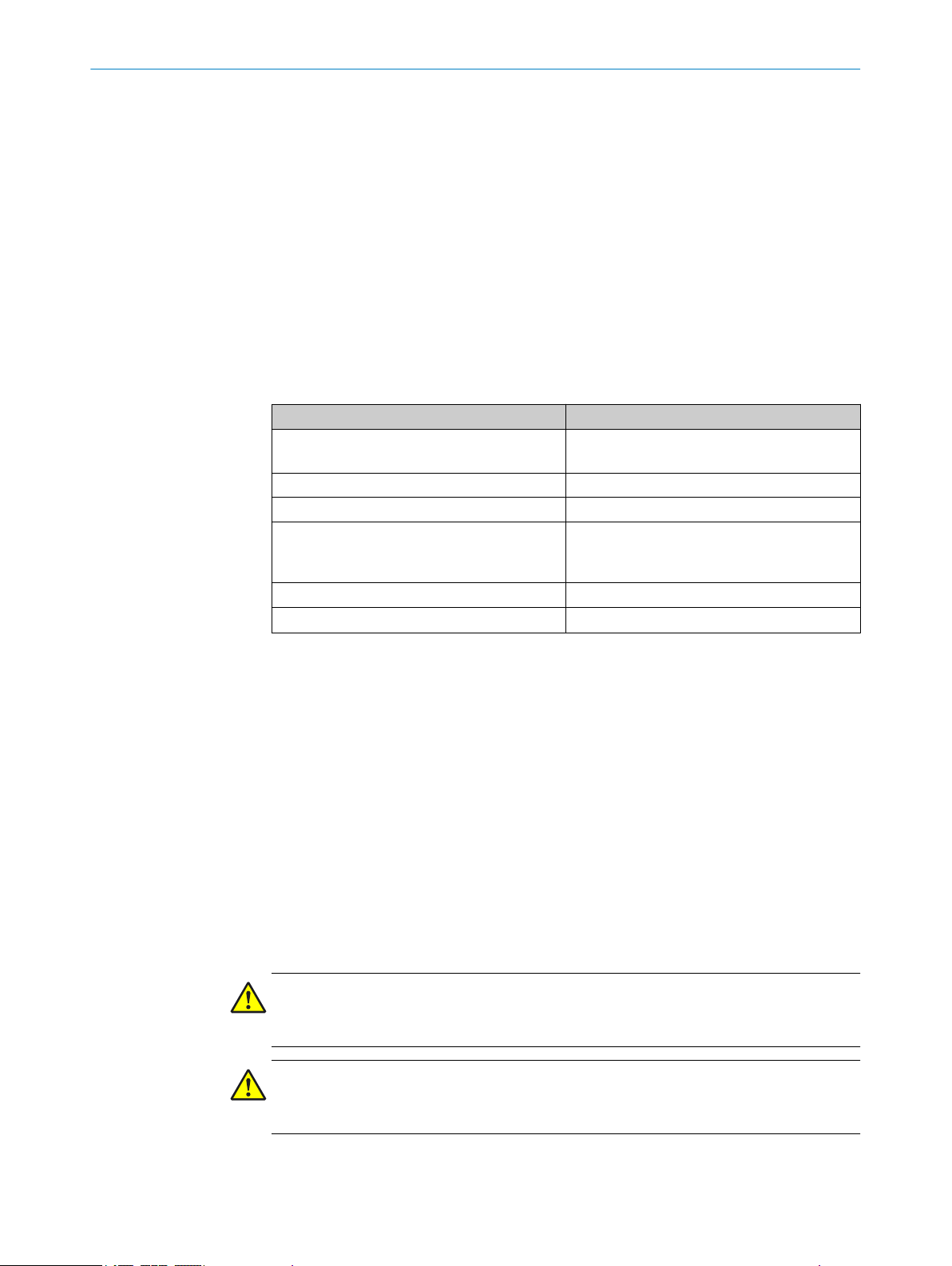
3.1 Structure and function
Structure
Figure 1: Structure of the TR110 Lock safety locking device
Safety switches
1
Coded actuator
2
Actuating head
3
Locking pin
4
The safety locking device is an interlocking device with a locking function. The safety
locking device consists of a safety switch and a coded actuator. The actuator has a high
coding level (uniquely coded).
Function
When the protective device is closed, the actuator is inserted into the actuating head of
the safety switch. In doing so, the locking pin is pressed downward by the actuator. If
the actuator reaches the end position, the locking pin moves into the provided hole of
the actuator.
Further functioning depends on whether the safety locking device is based on the
power to release or the power to lock principle.
In the power to release principle, the inserted actuator is immediately blocked and
•
the locking device is locked (to unlock the locking device, the locking solenoid
must be energized).
In the power to lock principle, the locking solenoid must be energized in order to
•
lock the locking device. If the locking solenoid is not energized, the actuator is only
held in position by retaining force (spring force). The actuator can be pulled out
again by overpowering the retaining force.
Complementary information
The code of the actuator is read out and evaluated using transponder technology.
•
•
If the code is valid, the door application diagnostic output (Out AUX DOOR)
switches to the ON state.
If the locking device is locked, the safe output signal switching devices (OSSD) are
switched to the ON state. In addition, the locking function application diagnostic
output (Out AUX LOCK) switches to the ON state.
8
O PE R AT I NG IN S TR U CT I ON S | TR110 Lock 8023119/15LY/2019-10-28 | SICK
Subject to change without notice
Page 9

If the locking device is locked, the actuator cannot be removed from the actuating
•
head.
The locking device can only be locked when the protective device is closed (pre‐
•
vention of incorrect closing).
3.2 Product characteristics
3.2.1 Product variants
Overview
The safety locking device is delivered with or without pushbuttons. You will find an
overview of important distinguishing features of the variants in the following.
PRODUCT DESCRIPTION 3
8023119/15LY/2019-10-28 | SICK O PE R AT I NG IN S TR U CT I ON S | TR110 Lock
Subject to change without notice
Figure 2: Device variants
TR110 Lock
1
TR110 Lock with pushbuttons
2
TR110 Lock
The TR110 Lock safety locking device differs between the following variants:
Power to lock principle
•
Power to release principle
•
Power to release principle with escape release
•
The variants also each have the following connection types:
For stand-alone connection, e.g. to a safety controller or a safety relay.
•
For connection to Flexi Loop
•
For OSSD cascading with T-connectors or in the control cabinet
•
TR110 Lock with pushbuttons
The TR110 Lock safety locking device with pushbuttons features two pushbuttons:
9
Page 10

3 PRODUCT DESCRIPTION
•
•
•
The TR110 Lock safety locking device with pushbuttons differs between the following
variants:
•
•
•
Further topics
•
3.2.2 OSSD
Output signal switching device: signal output for the protective device, which is used for
stopping the dangerous movement.
An OSSD is a safety switching output. The functionality of each OSSD is tested periodi‐
cally. OSSDs are always connected in pairs and must undergo dual-channel analysis for
safety reasons. An OSSD pair is formed from 2 OSSDs that are connected and analyzed
together.
The pushbuttons contain single-channel normally open contacts which can be
used to trigger control signals.
LEDs are located in the pushbuttons which can be controlled, e.g. to signal opera‐
tional statuses.
The pushbuttons can be assigned colors using cover caps.
Power to lock principle
Power to release principle
Power to release principle with escape release
"Ordering information", page 62
3.2.3 Application diagnostic outputs
Important information
NOTE
In the case of safety locking devices cascaded with T-connectors, the locking function
application diagnostic output (Out AUX LOCK) cannot be evaluated.
Different application diagnostic outputs
Depending on the device connection, the variants feature various application diagnostic
outputs.
Door application diagnostic output (Out AUX DOOR)
•
Locking device application diagnostic output (Out AUX LOCK)
•
Diagnostic application diagnostic output (Out AUX DIA)
•
3.2.4 Status indicators
The safety locking device indicates status information using multiple LEDs.
10
O PE R AT I NG IN S TR U CT I ON S | TR110 Lock 8023119/15LY/2019-10-28 | SICK
Subject to change without notice
Page 11

PRODUCT DESCRIPTION 3
Figure 3: Status LEDs
STATE
1
LOCK
2
DIA
3
Figure 4: Status LEDs
STATE
1
LOCK
2
DIAG
3
LEDs in the pushbuttons
4
8023119/15LY/2019-10-28 | SICK O PE R AT I NG IN S TR U CT I ON S | TR110 Lock
Subject to change without notice
11
Page 12
3 PRODUCT DESCRIPTION
Table 2: Status LEDs
Item Name Color
1
2
3
The variants with 2 pushbuttons feature two LEDs in the pushbuttons. The LEDs of the
pushbuttons are controlled using two inputs.
STATE Green
LOCK Yellow
DIA Red
3.3
Manual unlocking
In some situations, it necessary to unlock the locking device manually (e.g. if faults are
present). When unlocking, the safe output signal switching devices (OSSD) switch to the
OFF status. A stop command must be generated as a result.
Important information
NOTICE
After manual unlocking, a function test must be performed (see "Testing", page 37).
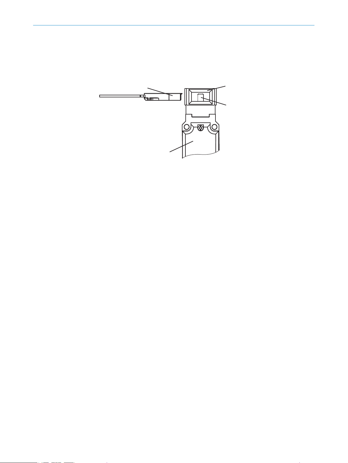
3.3.1 Mechanical unlocking mechanism
Using the mechanical unlocking mechanism, the safety locking device can be unlocked
regardless of the status.
Figure 5: Mechanical unlocking mechanism
1
2
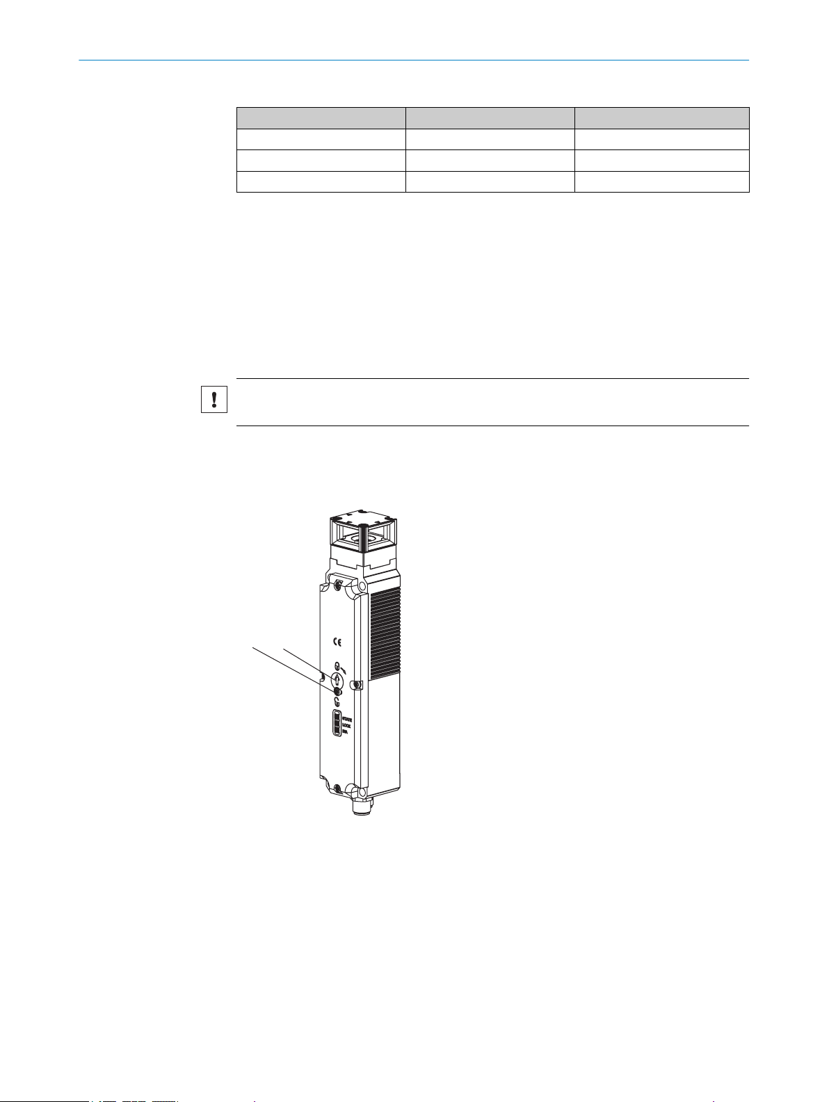
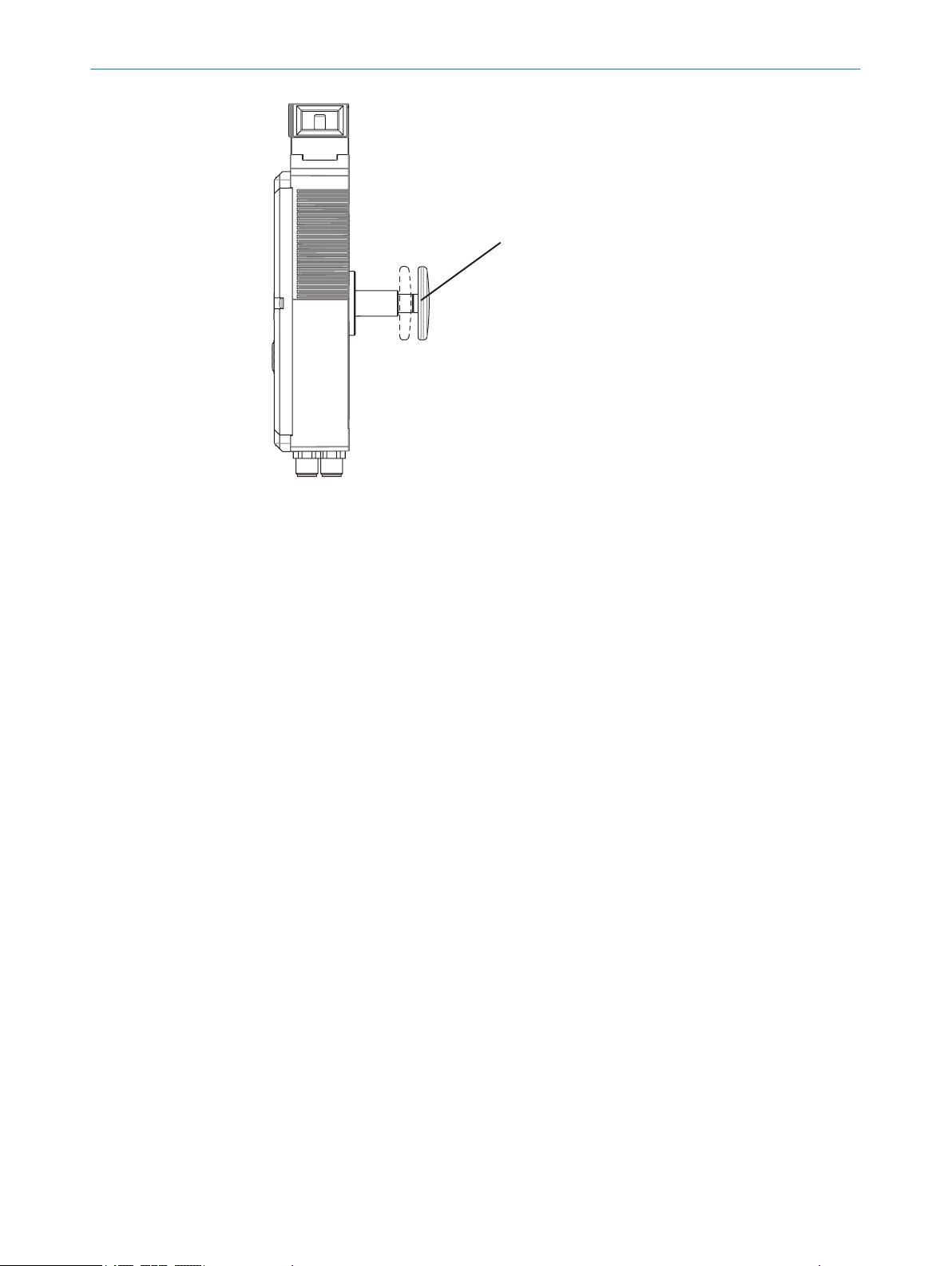
3.3.2 Emergency release
The emergency release can be retrofitted as an accessory. The emergency release can
be used to actuate the mechanical unlocking mechanism without tools.
12
O PE R AT I NG IN S TR U CT I ON S | TR110 Lock 8023119/15LY/2019-10-28 | SICK
Retaining screw
Mechanical unlocking mechanism
Subject to change without notice
Page 13
PRODUCT DESCRIPTION 3
NOTICE
The emergency release must be able to be actuated manually outside of the pro‐
•
tected area without tools.
The emergency release must have a label stating that it may only be actuated in
•
an emergency.
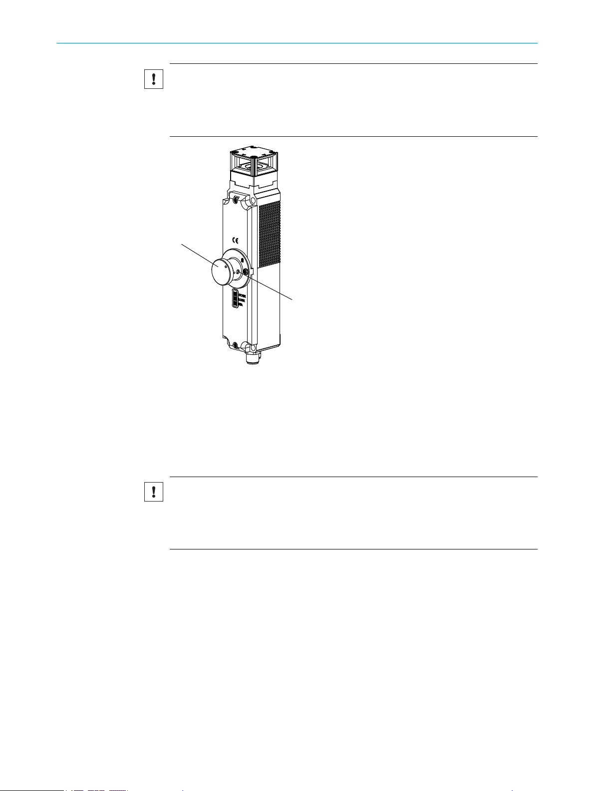
3.3.3 Escape release
Figure 6: Emergency release
Emergency release
1
Stop bolt
2
The escape release makes it possible to open a closed protective device without tools
from within the hazardous area.
NOTICE
The escape release must be able to be actuated manually from inside the pro‐
•
tected area without tools.
Mount the escape release so that actuation can only take place from inside of pro‐
•
tected area (hazardous area).
8023119/15LY/2019-10-28 | SICK O PE R AT I NG IN S TR U CT I ON S | TR110 Lock
Subject to change without notice
13
Page 14
3 PRODUCT DESCRIPTION
Figure 7: Escape release
1
Red button of the escape release
14
O PE R AT I NG IN S TR U CT I ON S | TR110 Lock 8023119/15LY/2019-10-28 | SICK
Subject to change without notice
Page 15
4 Project planning
4.1 Manufacturer of the machine
DANGER
Failure to comply with manufacturer’s obligations
Hazard due to lack of effectiveness of the protective device
Carry out a risk assessment before using the safety locking device.
b
Do not tamper with or modify the components of the safety locking device.
b
Make sure that the safety locking device is only repaired by the manufacturer or by
b
someone authorized by the manufacturer. Improper repair can lead to a loss of the
protective function.
Make sure that switch-on commands which bring about a dangerous state of the
b
machine are not enabled until the protective device is closed and the lock is acti‐
vated.
Make sure that the lock is not deactivated until the dangerous state of the
b
machine has stopped.
Make sure that closing a protective device and activating the lock does not cause
b
a dangerous machine function to start by itself. This must be controlled by a sepa‐
rate start command.
The safety locking device must not be bypassed (contacts jumpered), turned away,
b
removed, or rendered ineffective in any other way. Take measures to reduce
bypassing options as necessary.
PROJECT PLANNING 4
Observe EN ISO 14119 for using interlocking devices associated with physical guards.
4.2 Operator of the machine
DANGER
Failure to observe operator obligations
Hazard due to lack of effectiveness of the protective device
Changes to the machine and changes to the mechanical mounting of the safety
b
locking device necessitate a new risk assessment. The results of this risk assess‐
ment may require the operator of the machine to meet a manufacturer’s obliga‐
tions.
Apart from the procedures described in this document, the components of the
b
safety locking device must not be opened or modified.
Do not carry out any repair work on components. Improper repair of the safety
b
locking device can lead to a loss of the protective function.
Make sure that replacement actuators are not used for bypassing. Restrict access
b
to actuators.
4.3 Design
4.3.1 Selection of the actuator
NOTICE
Selecting unsuitable actuators or improper mounting can damage the device.
Select the right actuator (see table 26).
b
Pay attention to the door radius and mounting options (see "Actuator dimensional
b
drawings", page 55).
Pay attention to the door hinge.
b
8023119/15LY/2019-10-28 | SICK O PE R AT I NG IN S TR U CT I ON S | TR110 Lock
Subject to change without notice
15
Page 16
4 PROJECT PLANNING
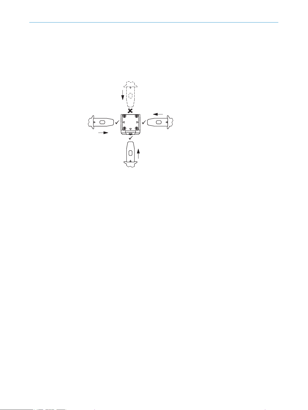
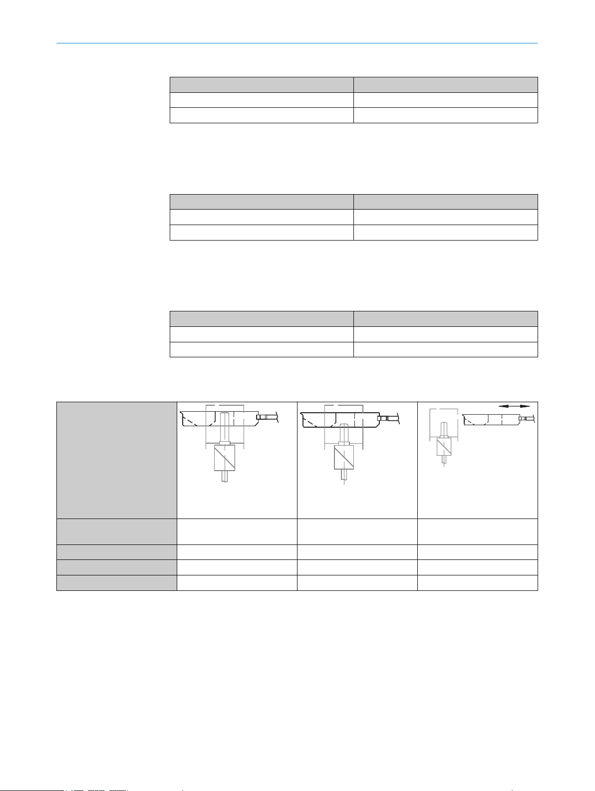
4.3.2 Actuating direction
Actuating direction
The safety locking device can be actuated from three horizontal directions (from the
left, from the front and from the right). If the safety locking device is to be actuated from
behind, an actuating head has to be used.
The safety locking device is not suited for an approach from a vertical angle.
4.3.3 Escape release
Figure 8: Directions of approach
Left
1
Front
2
Right
3
Rear (only possible with switched actuating head)
4
Further topics
"Changing the actuation direction", page 24
•
In order to mount the variant with the escape release, corresponding holes must be
made in the mounting surface.
The shaft of the escape release can be extended by 30 mm or 50 mm using with spac‐
ers
16
O PE R AT I NG IN S TR U CT I ON S | TR110 Lock 8023119/15LY/2019-10-28 | SICK
Subject to change without notice
Page 17

44/74/94
35
14
Figure 9: Escape release shaft
Escape release flange
1
Escape release shaft
2
Extension spacer
3
PROJECT PLANNING 4
4.4 Integration in the electrical control system
Switch-on commands that put the machine in a dangerous state may only be activated
when the protective device is closed and the locking device is locked. The locking
device may only be unlocked when the dangerous state has ended. Depending on the
safety concept, the signal is analyzed by safety relays or a safety controller, for example.
The connected controller and all devices responsible for safety must comply with the
required performance level and the required category (for example according to
ISO 13849-1).
The overall concept of the control system in which the safety locking device is inte‐
grated must be validated in accordance with ISO 13849-2.
4.4.1 Locking function
Prerequisites
A shared power supply is used for the control system and for the locking solenoids
•
of the safety locking device.
A clocked power supply is not used.
•
When connecting the locking solenoids to the output of a controller, this output
•
must supply sufficient current.
The activation of the locking solenoids of the safety locking device changes depending
on the locking principle.
8023119/15LY/2019-10-28 | SICK O PE R AT I NG IN S TR U CT I ON S | TR110 Lock
Subject to change without notice
Power to release principle
Locking the locking device: Close the protective device, no voltage on the magnet
•
Unlocking the locking device: Apply voltage to magnet
•
If voltage is interrupted at the magnet, the locking device remains locked and the pro‐
tective device cannot be opened immediately.
17
Page 18
4 PROJECT PLANNING
WARNING
The locking device locks even when voltage is not present
People could get trapped!
If people are in the hazardous area, do not close the protective device even if volt‐
b
age is not present.
Or:
Use the variant with an escape release.
b
Power to lock principle
Locking the locking device: Apply voltage to magnet
•
Unlocking the locking device: Disconnect voltage from magnet
•
If voltage is disconnected at the magnet, the locking device is unlocked and the protec‐
tive device can be opened immediately.
DANGER
Hazard due to lack of effectiveness of the protective device
In the event of a voltage drop, the safety locking device unlocks regardless of whether
the dangerous state of the machine has ended.
Assess the risk of accident. Use for protecting people requires correct project plan‐
b
ning.
Activating the locking function
For single-channel activation of the locking function, the controller and the safety lock‐
ing device must have the same ground.
For dual-channel activation of the locking function, clock pulses are tolerated up to a
max. length of 5 ms. If possible, switch off the clocking of outputs in the control system.
NOTICE
The locking solenoid of the TR110 Lock safety locking device is controlled exter‐
•
nally (no control function within the device). Therefore, the TR110 Lock safety lock‐
ing device does not have any characteristic safety values for controlling the locking
function.
The safety level for controlling the locking function is determined exclusively by
•
external control (e.g. by the PFHd of an external standstill monitor).
Types for series connection of OSSDs have a separate pin MAG 0 V DC in order to apply
0 V to the locking solenoids (see "Device connection", page 29). In the other types,
the 0 V connection of the locking solenoid is connected using the 0 V connection of the
safety locking device.
18
O PE R AT I NG IN S TR U CT I ON S | TR110 Lock 8023119/15LY/2019-10-28 | SICK
Subject to change without notice
Page 19
MAG +24 V DC
MAG 0 V DC
MAG +24 V DC
0 V
4.4.2 OSSDs
PROJECT PLANNING
Figure 10: Connection of the locking solenoid
In types for series connection of OSSDs
1
In all other types
2
Safety locking devices with local inputs and outputs can be directly integrated into the
machine controller.
4
DANGER
Hazard due to lack of effectiveness of the protective device
In the case of non-compliance, it is possible that the dangerous state of the machine
may not be stopped or not stopped in a timely manner.
Make sure that the following control and electrical requirements are met so the
b
protective function can be fulfilled.
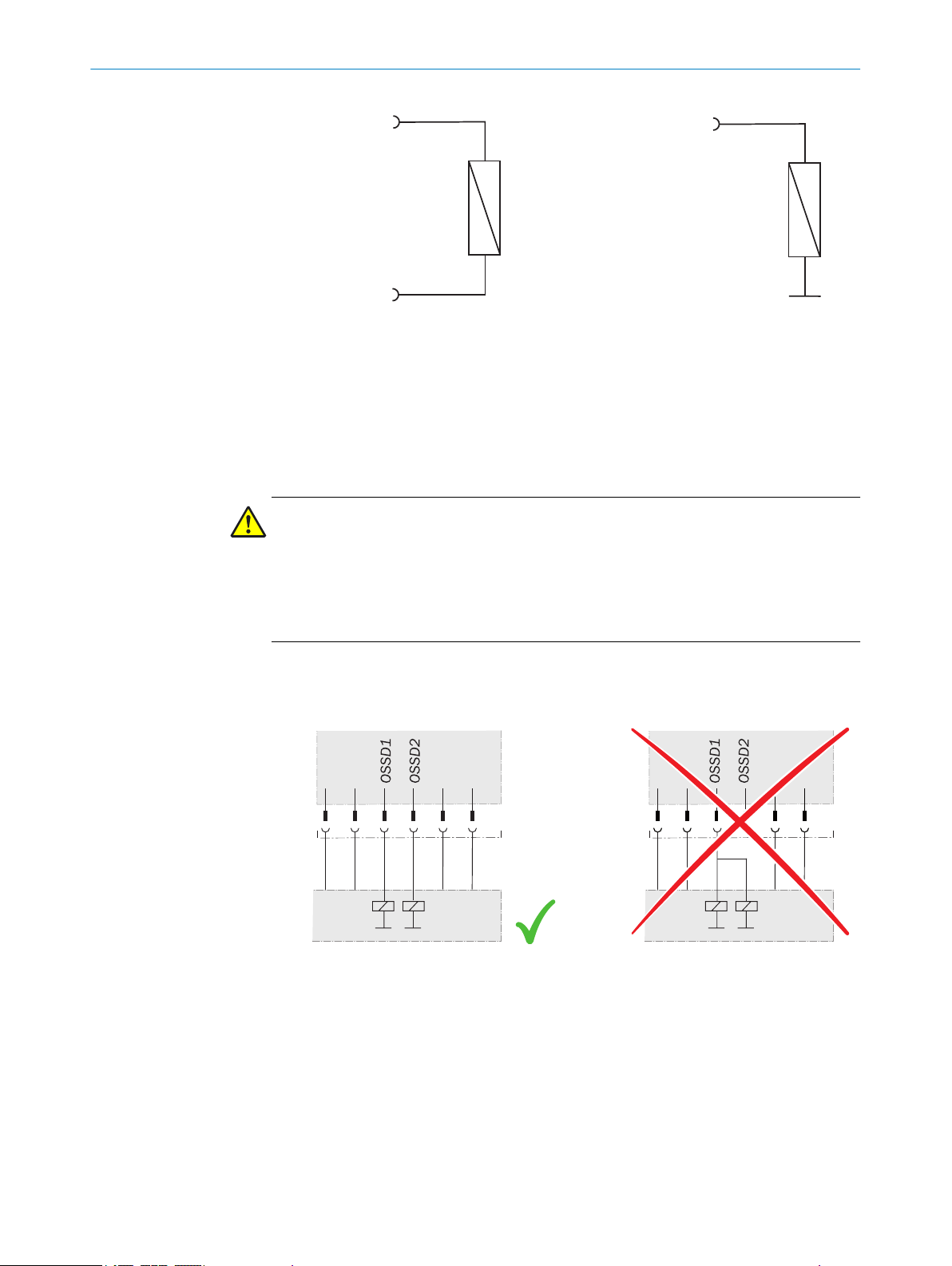
The output signals from an OSSD pair must not be connected to each other.
•
In the machine controller, both signals from an OSSD pair must be processed sep‐
•
arately.
Figure 11: Dual-channel and isolated connection of OSSD 1 and OSSD 2
The machine must switch to the safe state at any time if at least one OSSD in an
•
OSSD pair switches to the OFF state.
8023119/15LY/2019-10-28 | SICK O PE R AT I NG IN S TR U CT I ON S | TR110 Lock
Subject to change without notice
19
Page 20
4 PROJECT PLANNING
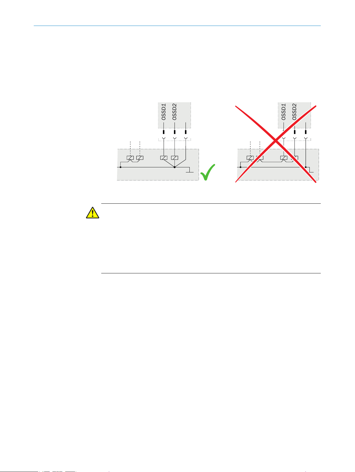
Prevent the formation of a potential difference between the load and the protec‐
•
tive device. If you connect loads to the OSSDs (safety outputs) that then also
switch if controlled with negative voltage (e.g. electro-mechanical contactor with‐
out reverse polarity protection diode), you must connect the 0 V connections of
these loads and those of the corresponding protective device individually and
directly to the same 0 V terminal strip. In the event of a fault, this is the only way to
ensure that there can be no potential difference between the 0 V connections of
the loads and those of the corresponding protective device.
Figure 12: No potential difference between load and protective device
DANGER
Hazard due to lack of effectiveness of the protective device
In the case of non-compliance, it is possible that the dangerous state of the machine
may not be stopped or not stopped in a timely manner.
Downstream contactors must be positively guided and monitored depending on applic‐
able national regulations or required reliability of the safety function.
Make sure that downstream contactors are monitored (external device monitoring,
b
EDM).
The OSSDs are short-circuit protected to 24 V DC and 0 V. If the safety locking device is
locked, the OSSDs signal the ON state with the HIGH signal level (non-isolated). If the
safety locking device is unlocked or there is a device fault, the OSSDs signal the OFF
state with the LOW signal level.
Do not use a control system with clocking or switch off the clocking function of the con‐
trol system. The device generates its own test pulses at the OSSDs. A downstream con‐
troller must tolerate these test pulses, which can have a length of up to 1 ms. The test
pulses are also output when the OSSDs are switched off. Depending on the sluggish‐
ness of the downstream device (controller, relay, etc.), this can lead to short switching
processes.
For inductive loads, the OSSDs must be protected with a freewheeling diode. RC sup‐
pressors must not be used:
4.4.3 Application diagnostic outputs
Door application diagnostic output (Out AUX DOOR)
The signal of the door application diagnostic output changes as soon as the actuator is
moved into or leaves the response range of the safety switch. In other words, the output
signal changes when the protective device is opened and closed. This is not a safety
output.
20
O PE R AT I NG IN S TR U CT I ON S | TR110 Lock 8023119/15LY/2019-10-28 | SICK
Subject to change without notice
Page 21
PROJECT PLANNING 4
Table 3: Switching behavior of the door application diagnostic output
Actuator Door application diagnostic output
Actuator not in response range OFF
Actuator in response range ON
Locking function application diagnostic output (Out AUX LOCK)
The signal of the locking function application diagnostic output changes as soon as the
locking function has been activated. This is not a safety output.
Table 4: Switching behavior of the locking function application diagnostic output
Locking function Locking function application diagnostic output
Locking function active ON
Locking function not active OFF
Fault application diagnostic output (Out AUX DIA)
The signal of the fault application diagnostic output changes as soon as a fault occurs.
This is not a safety output.
Table 5: Switching behavior of the fault application diagnostic output
Fault Fault application diagnostic output
Fault has occurred ON
No fault OFF
4.4.4 Switching behavior
Table 6: Switching behavior
Figure 15: Protective device
Figure 13: Protective device
closed and locked
Activating the locking func‐
tion
OSSDs ON OFF OFF
Out AUX LOCK ON OFF OFF
Out AUX DOOR ON ON OFF
ON OFF Not relevant
Figure 14: Protective device
closed but not locked
open
4.4.5 Safe series connection
OSSDs of several safety locking devices can be connected by safe series connection.
The connected OSSDs act like the OSSDs of a single device.
8023119/15LY/2019-10-28 | SICK O PE R AT I NG IN S TR U CT I ON S | TR110 Lock
Subject to change without notice
21
Page 22

2
8
4
7
3
5
6
1
OSSD1
OSSD2
24 V DC
0 V DC
/
4
1
2
3
5
2
8
4
7
3
5
6
1
OSSD1
OSSD2
/
4
1
2
3
5
2
8
4
7
3
5
6
1
OSSD1
OSSD2
/
4
1
2
3
5
4 PROJECT PLANNING
Figure 16: Safe series connection
TR110 Lock
1
Safe evaluation unit
2
Male connector, M12, 8-pin
3
Male connector, M12, 5-pin
4
NOTICE
Connect the enable inputs of the OSSDs In 1 and In 2 directly to a power supply
•
unit (+24 VDC) or to the outputs OSSD 1 and OSSD 2 of another TR110 Lock
safety locking device.
There must not be any clocked controller signals at inputs In 1 and In 2.
•
The maximum number of safety locking devices depends on the following factors:
Applied supply voltage
•
Length of cables used
•
Cable cross-section of cables used
•
Load current
•
The voltage drop in the safe series connection has to be checked so that the defined
minimum voltage is still applied to the last safety locking device.
The number of safety locking devices in a safe series connection influences the
response time of the system (see table 17, page 45).
The safe series connection can be implemented using special T-connectors and an end
connector (see "Connection of a safe series connection", page 32).
4.4.6 Protection of the voltage supply
The voltage supply must be provided with fuse protection depending on the number of
safety locking devices and the required current for the outputs.
22
O PE R AT I NG IN S TR U CT I ON S | TR110 Lock 8023119/15LY/2019-10-28 | SICK
Max. current consumption of a single safety locking device I
I
= I
max
I
TR110
I
OSSD1
I
OSSD2
I
OAUXL
+ I
TR110
= Operating current of the TR110 Lock safety locking device
= Load current of OSSD 1 (max. 150 mA)
= Load current of OSSD 2 (max. 150 mA)
= Load current of locking function application diagnostic output (max. 50 mA)
OSSD1+IOSSD2
+ I
OAUXL
+ I
OAUXD
max
:
Subject to change without notice
Page 23

PROJECT PLANNING 4
I
= Load current of door application diagnostic output (max. 50 mA)
OAUXD
Max. current consumption of a safe series connection of safety locking devices I
:
cade
I
= I
Cascade
n = Number of connected safety locking devices
OSSD1
+ I
OSSD2
+ n × (I
TR110
+ I
OAUXL
+ I
OAUXD
)
Cas‐
4.5
Testing plan
The safety locking device must be tested by appropriately qualified safety personnel
when commissioning, after modifications, and at regular intervals.
The regular thorough checks serve to investigate the effectiveness of the safety locking
device and discover defects because of modifications or external influences (such as
damage or tampering).
The manufacturer and user must define the type and frequency of the thorough checks
on the machine on the basis of the application conditions and the risk assessment.
Determination of the thorough checks must be documented in a traceable manner.
8023119/15LY/2019-10-28 | SICK O PE R AT I NG IN S TR U CT I ON S | TR110 Lock
Subject to change without notice
23
Page 24

C
B
D
A
5 MOUNTING
5 Mounting
5.1 Safety
DANGER
Hazard due to unexpected starting of the machine
Death or severe injury
Make sure that the dangerous state of the machine is and remains switched off.
b
NOTICE
If incorrectly installed or if the ambient conditions are not suitable, the safety locking
device can be damaged.
Arrange the safety switch and actuator so that damage due to unintentional out‐
b
side influences is prevented.
Do not use a safety switch and actuator as a stop.
b
The set-up and mounting of the safety switch and actuator must be stable enough
b
to maintain proper operation.
Use only reliable mounting elements that can only be removed with tools.
b
If an opening is created in the physical guard due to alignment errors, it must not
b
impair the protective function.
5.2 Changing the actuation direction
Overview
The safety locking device can be actuated from three directions (A, B and C). The actua‐
tion direction only needs to be changed if the safety locking device is to be actuated
from behind (D).
Figure 17: Changing the direction of approach
Approach
24
1. Loosen the screws on the actuating head.
2. Turn the actuating head in the desired direction.
3. Tighten the screws to 1.2 Nm.
O PE R AT I NG IN S TR U CT I ON S | TR110 Lock 8023119/15LY/2019-10-28 | SICK
Subject to change without notice
Page 25

5.3 Mounting the safety switch
Important information
NOTICE
The actuator must not be used for guiding or used as a stop.
Prerequisites
To mount on the machine, the safety switch and actuator must be put together.
•
A clearance of 12 mm must be maintained around the actuating head.
•
Approach
The safety locking device may be in any installation position.
Mount the safety switch using 4 × M5 screws.
b
Observe the maximum tightening torque of 1.4 Nm.
b
MOUNTING 5
Figure 18: Mounting the safety switch
Mounting holes
1
12 mm clearance for actuator
2
Complementary information
Mounting brackets are available for the actuator and safety locking device as acces‐
sories (see "Dimensional drawings of the mounting bracket", page 60).
5.4 Mounting straight and angled actuators
Important information
NOTICE
The actuator must not be used for guiding or used as a stop.
8023119/15LY/2019-10-28 | SICK O PE R AT I NG IN S TR U CT I ON S | TR110 Lock
Subject to change without notice
25
Page 26

5 MOUNTING
Prerequisites
To mount on the machine, the safety switch and actuator must be put together.
Approach
Mount the actuator using 2 × M4 screws.
b
Complementary information
Mounting brackets are available for the actuator and safety locking device as acces‐
sories (see "Dimensional drawings of the mounting bracket", page 60).
5.5 Mounting the radius actuator
Important information
NOTICE
The actuator must not be used for guiding or used as a stop.
Prerequisites
To mount on the machine, the safety switch and actuator must be put together.
•
The actuator must be positioned perpendicularly to the guide slot before insertion.
•
Approach
1. Mount the actuator using 2 × M5 screws.
2. For larger radii, the actuator can be aligned using the adjustment screw.
Figure 19: Adjustment screw for alignment
Adjustment screw
1
Complementary information
Mounting brackets are available for the actuator and safety locking device as acces‐
sories (see "Dimensional drawings of the mounting bracket", page 60).
5.6 Mounting the escape release
26
Prerequisites
Hole in the mounting surface for the escape release (see "Escape release",
•
page 16).
Spacers with lengths of 30 mm or 50 mm for the escape release shaft (optional).
•
O PE R AT I NG IN S TR U CT I ON S | TR110 Lock 8023119/15LY/2019-10-28 | SICK
Subject to change without notice
Page 27
Approach
1
1. Unscrew the red button of the escape release.
2. Extend the escape release shaft if necessary.
3. Insert the escape release shaft through the hole.
4. Mount the safety switch using 4 × M5 screws.
5. Screw on the red button of the escape release.
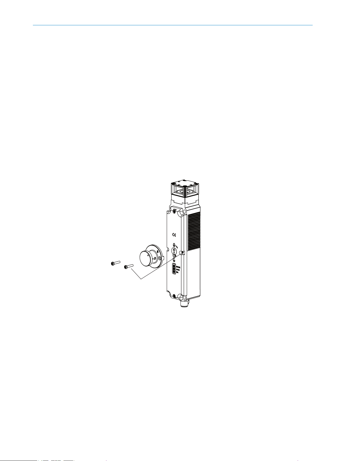
5.7 Mounting the emergency unlocking
Approach
1. Remove the center screws on the cover of the safety switch.
2. Remove the retaining screw of the mechanical unlocking mechanism.
3. Position the emergency release so that the blade of the emergency release can
reach into the slot of the mechanical unlocking mechanism.
4. Ensure that the emergency release is blocked by the ball catch, not by the stop
bolt.
5. Fasten the emergency release using the included screws M3 × 17. Tighten the
screws to 0.5 Nm.
6. Seal the emergency release.
MOUNTING 5
Figure 20: Mounting the emergency release
Screws of the safety switch
1
5.8 Mounting the cover caps
Approach
1. Turn the cover cap so that the point is pointing upward.
2. Insert the cover caps onto the pushbuttons.
3. Press on the cover caps until they audibly snap in.
8023119/15LY/2019-10-28 | SICK O PE R AT I NG IN S TR U CT I ON S | TR110 Lock
Subject to change without notice
27
Page 28

Click!
5 MOUNTING
Figure 21: Cover cap mount‐
ing, step 1
5.9 Removing the cover caps
Approach
1. Carefully guide a small slot screwdriver between the bracket and cover cap.
2. Carefully lift out the cover cap.
Figure 24: Cover cap removal, step 1 Figure 25: Cover cap removal, step 2
Figure 22: Cover cap mount‐
ing, step 2
Figure 23: Cover cap mount‐
ing, step 3
28
O PE R AT I NG IN S TR U CT I ON S | TR110 Lock 8023119/15LY/2019-10-28 | SICK
Subject to change without notice
Page 29

6 Electrical installation
6.1 Safety
DANGER
Hazard due to electrical voltage
Hazard due to unexpected starting of the machine
Make sure that the machine is and remains disconnected from the power supply
b
during electrical installation.
Make sure that the dangerous state of the machine is and remains switched off
b
during electrical installation.
Make sure that the outputs of the safety locking device have no effect on the
b
machine during electrical installation.
DANGER
Incorrect connection of the safety locking device
Loss of safety function
In the case of insulating material/connection strands, observe the necessary tem‐
b
perature resistance and mechanical load capability.
Only use safe contacts for safety functions.
b
ELECTRICAL INSTALLATION 6
6.2
6.3
Notes on cULus
For use according to the requirements of UL 508, the following conditions must also be
met:
A power supply marked as “for use in class 2 circuits” must be used.
•
Alternative solutions must correspond to the following requirements: Electrically
•
isolated power supply unit with fuse protection in accordance with UL248. This
fuse should be rated for max. 3.3 A and be integrated in the 30 V DC voltage sec‐
tion.
A connecting cable must be used that is listed under UL Category Code CYJV / 7,
•
min. 24 AWG, min. 80 °C.
Device connection
Prerequisites
All electrical connections must be isolated from the supply network either through
•
safety transformers in accordance with IEC 61558‑2‑6 with output voltage limita‐
tion or through equivalent isolation measures (PELV).
Power devices that represent a strong source of interference must be locally iso‐
•
lated from the input and output circuits for signal processing. The cable routing of
the safety circuits should be separated from the cables of the power circuits by the
greatest possible distance.
In order to avoid EMC disturbances, the physical ambient and operating conditions
•
at the installation location of the device must comply with the requirements of
IEC 60204-1.
8023119/15LY/2019-10-28 | SICK O PE R AT I NG IN S TR U CT I ON S | TR110 Lock
Subject to change without notice
29
Page 30

8
2
3
4
5 7
1
6
8
2
3
4
5 7
1
6
6 ELECTRICAL INSTALLATION
Stand-alone connection
Figure 26: Device connection (male connector, M12, 8-pin, A-coded)
Table 7: Device connection pin assignment (male connector, M12, 8-pin, A-coded)
Pin Wire color
1 White Out AUX DOOR Door application diagnostic out‐
2 Brown 24 V DC Voltage supply 24 V DC
3 Green MAG +24 V DC Magnet activation 24 V DC
4 Yellow Out AUX DIA Fault application diagnostic out‐
5 Gray OSSD 1 Output OSSD 1
6 Pink OSSD 2 Output OSSD 2
7 Blue 0 V Voltage supply 0 V DC
8 Red Out AUX LOCK Locking device application diag‐
1)
Applies to the extension cables recommended as accessories.
1)
Designation Description
put (not safe)
put (not safe)
nostic output (not safe)
For connection to Flexi Loop
Figure 27: Device connection (male connector, M12, 8-pin, A-coded)
Table 8: Device connection pin assignment for Flexi Loop variant (M12, 8-pin)
Pin Wire color
1 White Out AUX DOOR Door application diagnostic out‐
2 Brown 24 V DC Voltage supply 24 V DC
3 Green MAG +24 V DC Magnet activation 24 V DC
4 Yellow N.C. Not assigned
5 Gray OSSD 1 Output OSSD 1
6 Pink OSSD 2 Output OSSD 2
7 Blue 0 V Voltage supply 0 V DC
8 Red N.C. Not assigned
1)
Applies to the extension cables recommended as accessories.
1)
Designation Description
put (not safe)
30
O PE R AT I NG IN S TR U CT I ON S | TR110 Lock 8023119/15LY/2019-10-28 | SICK
Subject to change without notice
Page 31

8
2
3
4
5 7
1
6
12
3 4
5
8
2
3
4
5 7
1
6
ELECTRICAL INSTALLATION 6
For safe series connection
Figure 28: Device connection (male connector, M12, 8-pin, A-coded)
Table 9: Device connection pin assignment (male connector, M12, 8-pin, A-coded)
Pin Wire color
1 White Out AUX LOCK Locking device application diag‐
2 Brown 24 V DC Voltage supply 24 V DC
3 Green RST Hardware reset connection
4 Yellow In 2 Enable input for OSSD 2
5 Gray OSSD 1 Output OSSD 1
6 Pink OSSD 2 Output OSSD 2
7 Blue 0 V Voltage supply 0 V DC
8 Red In 1 Enable input for OSSD 1
1)
Applies to the extension cables recommended as accessories.
2)
When used as an individual safety locking device or as the first safety locking device in a safe series con‐
nection, apply 24 V DC.
1)
Designation Description
nostic output (not safe)
2)
2)
Figure 29: Device connection (male connector, M12, 5-pin, A-coded)
Table 10: Device connection pin assignment (male connector, M12, 5-pin, A-coded)
Pin Wire color
1)
Designation Description
1 Brown MAG 0 V DC Input for locking device 0 V DC
2 White Out AUX DOOR Door application diagnostic out‐
put (not safe)
3 Blue Out AUX DIA Fault application diagnostic out‐
put (not safe)
4 Black MAG +24 V DC Input for locking device 24 V DC
5 Gray N.C. Not assigned
1)
Applies to the extension cables recommended as accessories.
Variant with two pushbuttons
Figure 30: Device connection (male connector, M12, 8-pin, A-coded)
8023119/15LY/2019-10-28 | SICK O PE R AT I NG IN S TR U CT I ON S | TR110 Lock
Subject to change without notice
31
Page 32

12
3 4
5
6 ELECTRICAL INSTALLATION
Table 11: Device connection pin assignment (male connector, M12, 8-pin, A-coded)
Pin Wire color
1 White Out AUX DOOR Door application diagnostic out‐
2 Brown 24 V DC Voltage supply 24 V DC
3 Green MAG +24 V DC Magnet activation 24 V DC
4 Yellow Out AUX DIA Fault application diagnostic out‐
5 Gray OSSD 1 Output OSSD 1
6 Pink OSSD 2 Output OSSD 2
7 Blue 0 V Voltage supply 0 V DC
8 Red Out AUX LOCK Locking device application diag‐
1)
Applies to the extension cables recommended as accessories.
1)
Designation Description
put (not safe)
put (not safe)
nostic output (not safe)
Figure 31: Device connection (male connector, M12, 5-pin, A-coded)
Table 12: Device connection pin assignment (male connector, M12, 5-pin, A-coded)
Pin Wire color
1 White NO 1 Pushbutton 1 output (normally
2 Brown LED 1 LED 1 input
3 Green NO 2 Pushbutton 2 output (normally
4 Black LED 2 LED 2 input
5 Gray RST Hardware reset connection
1)
Applies to the extension cables recommended as accessories.
1)
Designation Description
6.4 Connection of a safe series connection
Overview
A maximum of 20 devices can be activated in series. The safe series connection can be
implemented using special T-connectors and an end connector. The safe evaluation
unit switches off the machine if a protective device is opened or a fault occurs at a
safety locking device.
Important information
open)
open)
32
NOTE
The locking device control (MAG 0 V DC), the application diagnostic outputs door
•
(Out AUX DOOR) and error application diagnostic outputs have to be wired sepa‐
rately.
In the case of safety locking devices cascaded with T-connectors, the locking
•
device application diagnostic output (Out AUX LOCK) cannot be evaluated.
Mount the connecting cable so that individual T-connectors (and thus a safety
•
locking device) cannot be easily jumpered.
O PE R AT I NG IN S TR U CT I ON S | TR110 Lock 8023119/15LY/2019-10-28 | SICK
Subject to change without notice
Page 33

55
44
33
2
2
1
1
5
6 7
8
4
321
ELECTRICAL INSTALLATION
Connection of the safe series connection (M12, 5-pin)
6
Figure 32: Safe series connection of several safety locking devices
TR110 Lock safety locking device
1
Connection cable, M12, 8-pin
2
T-connector
3
Connection cable (M12, 5-pin)
4
Connecting cable, M12, 5-pin, for connecting the safe series connection
5
Connecting cable, M12, 5-pin, for connecting the locking device controller
6
Safe evaluation unit
7
End connector
8
Figure 33: Internal circuitry: T-connector for safe series connection
8023119/15LY/2019-10-28 | SICK O PE R AT I NG IN S TR U CT I ON S | TR110 Lock
Subject to change without notice
33
Page 34

5
4
3
2
1
12
3 4
5
6 ELECTRICAL INSTALLATION
Figure 34: Internal circuitry: end connector for safe series connection
The 5-pin male connector of the last T-connector upstream of the safe evaluation unit is
the interface between the safe series connection and the safe evaluation unit.
Figure 35: Connection of the safe series connection (M12, 5-pin, A-coded, male connector)
Table 13: Pin assignment connection of the safe series connector (male connector, M12, 5-pin,
A-coded)
Pin Wire color
1 Brown +24 V DC Voltage supply 24 V DC
2 White OSSD 1 OSSD 1 output
3 Blue 0 V Voltage supply 0 V DC
4 Black OSSD 2 OSSD 2 output
5 Gray RST Hardware reset connection
1)
Applies to the extension cables recommended as accessories.
2)
All switches of a chain can be reset simultaneously with the RST input (reset input). For this, a voltage of
24 V must applied to the RST input for at least 3 s.
If the RST input is not used, it must be connected to 0 V.
1)
Designation Description
34
Further topics
"Accessories", page 63
•
O PE R AT I NG IN S TR U CT I ON S | TR110 Lock 8023119/15LY/2019-10-28 | SICK
Subject to change without notice
Page 35

7 Commissioning
7.1 Switching on
The device initializes after it is switched on. The OSSDs are in the OFF state during this
and the STATE LED flashes green at 5 Hz.
7.2 Teach-in
7.2.1 Safety
DANGER
Bypassing the protective device
The dangerous state may not be stopped in the event of non-compliance.
Document teaching-in of an actuator.
b
During regular thorough checks, make sure that the taught-in actuator is still being
b
used.
An actuator must be taught-in during commissioning. Only the most recently taught-in
actuator is valid.
COMMISSIONING 7
During a teach-in operation, the OSSDs are in the OFF state, i.e. the system is in a safe
state.
7.2.2 Teaching-in the first actuator in delivery condition
Important information
NOTE
Safety locking devices switched on in delivery condition have a teach-in readiness with
no time limitation.
NOTE
The teach-in process is invalid if canceled, e.g. by interruption of the voltage supply or
removal of the actuator.
Then the TR110 Lock safety locking device enters the safe error state, the DIA LED
lights up red, the STATE LED flashes (see "System status", page 42).
Approach
1. Apply the supply voltage to the safety switch.
✓
The STATE LED flashes 3 times repeatedly.
2. Insert the actuator into the actuating head (close the protective device).
✓
The teach-in process starts, the STATE LED flashes at approx. 1 Hz.
The teach-in process is completed after about 30 seconds. The STATE and DIA
LEDs flash in alternation.
3. Switch off the supply voltage at the safety switch for at least 3 seconds and then
switch it back on.
✓
The code for the actuator that was just taught-in is enabled in the safety switch.
4. Check the effectiveness of the protective device.
8023119/15LY/2019-10-28 | SICK O PE R AT I NG IN S TR U CT I ON S | TR110 Lock
Subject to change without notice
35
Page 36

7 COMMISSIONING
7.2.3 Teaching-in the new actuator
Overview
The TR110 Lock safety locking device can be operated only with the actuator that was
last taught-in.
Important information
NOTE
Safety locking devices with an actuator that has already been taught-in have a teach-in
readiness of approx. 3 minutes after being switched on.
NOTE
If the safety switch detects an actuator that has already been taught-in, then the
•
teach-in process is canceled and the safety switch returns to normal mode.
If the safety switch detects a blocked code of a direct predecessor actuator, then
•
the teach-in process is canceled and the code of the previous actuator remains
active. The safety switch goes into an error state (see "System status", page 42).
Approach
1. Apply the supply voltage to the safety switch.
✓
The STATE LED flashes 3 times repeatedly.
2. Insert the actuator into the actuating head within 3 minutes.
3. The teach-in process starts, the STATE LED flashes at approx. 1 Hz.
✓
The teach-in process is completed after about 30 seconds. The STATE and DIA
LEDs flash in alternation.
4. Switch off the supply voltage at the safety switch for at least 3 seconds and then
switch it back on.
✓
This activates the new code and deactivates the old code.
5. Check the effectiveness of the protective device.
Complementary information
When a new actuator is taught-in, the safety switch blocks the code of the last actuator.
The latter cannot be taught-in again immediately when a new teach-in operation is per‐
formed. The blocked code is released again in the safety switch only after a third code
has been taught-in.
7.2.4 Teaching-in the actuator in safe series connection
Important information
NOTE
It is recommended to teach in the actuators not in the safe series connection, but indi‐
vidually.
36
Prerequisites
If the actuators need to be taught-in in a safe series connection, then it has to be possi‐
ble to switch from 0 V DC to 24 V DC at the RST inputs of the safety switches.
O PE R AT I NG IN S TR U CT I ON S | TR110 Lock 8023119/15LY/2019-10-28 | SICK
Subject to change without notice
Page 37

2
8
4
7
3
5
6
1
4
1
2
3
5
2
8
4
7
3
5
6
1
4
1
2
3
5
2
8
4
7
3
5
6
1
4
1
2
3
5
Figure 36: Connection to RST input
TR110 Lock
1
Male connector, M12, 8-pin
2
Signal for changing from 0 V DC to 24 V DC at RST
3
COMMISSIONING 7
Approach
Apply supply voltage to the safety switches.
b
✓
The STATE LEDs flash 3 times repeatedly.
Insert the actuators into the actuating heads.
b
Connect the RST to +24 V DC for at least 3 s.
b
The teach-in process on the safety switches of the safe series connection begins;
b
the STATE LEDs flash at approx. 1 Hz.
✓
The teach-in process is completed after about 30 seconds. The STATE and DIA
LEDs flash in alternation.
Reconnect the RST to +24 V DC for at least 3 s.
b
✓
The code for the actuators that were just taught-in is enabled in the safety
switches.
Check the effectiveness of all protective devices in the safe series connection.
b
7.3 Testing
DANGER
Hazard due to unexpected starting of the machine
Death or severe injury
Before carrying out the functional test, make sure that there are no people in the
b
hazardous area.
8023119/15LY/2019-10-28 | SICK O PE R AT I NG IN S TR U CT I ON S | TR110 Lock
Subject to change without notice
Approach
Check that the device is functioning properly after installation and after every fault. To
do this, proceed as follows:
Mechanical functional test
Open the protective device and close it again. The components of the safety lock‐
b
ing device must not collide with other parts. When the protective device is closed,
the actuator must be in a position which enables the lock to be actuated.
37
Page 38

7 COMMISSIONING
Electrical functional test
1. Switch on the supply voltage.
2. Close all protective devices and activate the locks. The machine must not start up
on its own.
3. Check the lock. It must not be possible to open the protective device.
4. Start the machine function.
5. Make sure that the lock cannot be deactivated as long as the dangerous machine
function is active.
6. Stop the machine function and deactivate the lock.
7. Check whether the protective device is kept locked until there is no more risk of
injury (e.g., due to run-on movements).
8. Check the restart interlock. The machine function must not start while the lock is
deactivated.
9. Repeat steps 3 to 8 individually for each protective device.
Complementary information
NOTE
With the version in accordance with the power to lock principle, an active lock com‐
mand can be simulated by applying 24 V DC voltage to the “Lock input” contact.
7.4 Regular thorough check
Important information
DANGER
Insufficient checks or incorrect repair
Hazard due to lack of effectiveness of the protective device
In the event of wear or damage, replace the entire safety locking device with actu‐
b
ator. Never replace individual parts or assemblies.
Check the safety locking device following the inspection intervals specified in the
b
national rules and regulations.
Monitoring
The following checks must be done to ensure permanent and proper function:
Proper switching function
•
Safe mounting of all components
•
No damage, contamination, deposits or wear
•
No loose plug connectors
•
No manipulation by employees
•
38
O PE R AT I NG IN S TR U CT I ON S | TR110 Lock 8023119/15LY/2019-10-28 | SICK
Subject to change without notice
Page 39

8 Operation
8.1 Actuating the mechanical unlocking mechanism
Approach
1. Ensure that actuators are not under tensile stress.
2. Loosen the retaining screw with the screwdriver.
3. Use the screwdriver to rotate the mechanical unlocking mechanism in the direc‐
tion of the arrow to the following symbol:
✓
The locking device is unlocked.
OPERATION 8
Figure 37: Actuating the mechanical unlocking mechanism
Retaining screw
1
Mechanical unlocking mechanism
2
8.1.1 Moving the mechanical unlocking mechanism back after use
Approach
Use the screwdriver to move the mechanical unlocking mechanism back to the fol‐
b
lowing symbol:
Screw in the retaining screw and seal it (e.g. with locking varnish)
b
Open the protective device and close it again.
b
✓
The safety locking device operates in normal mode again.
Carry out a functional test.
b
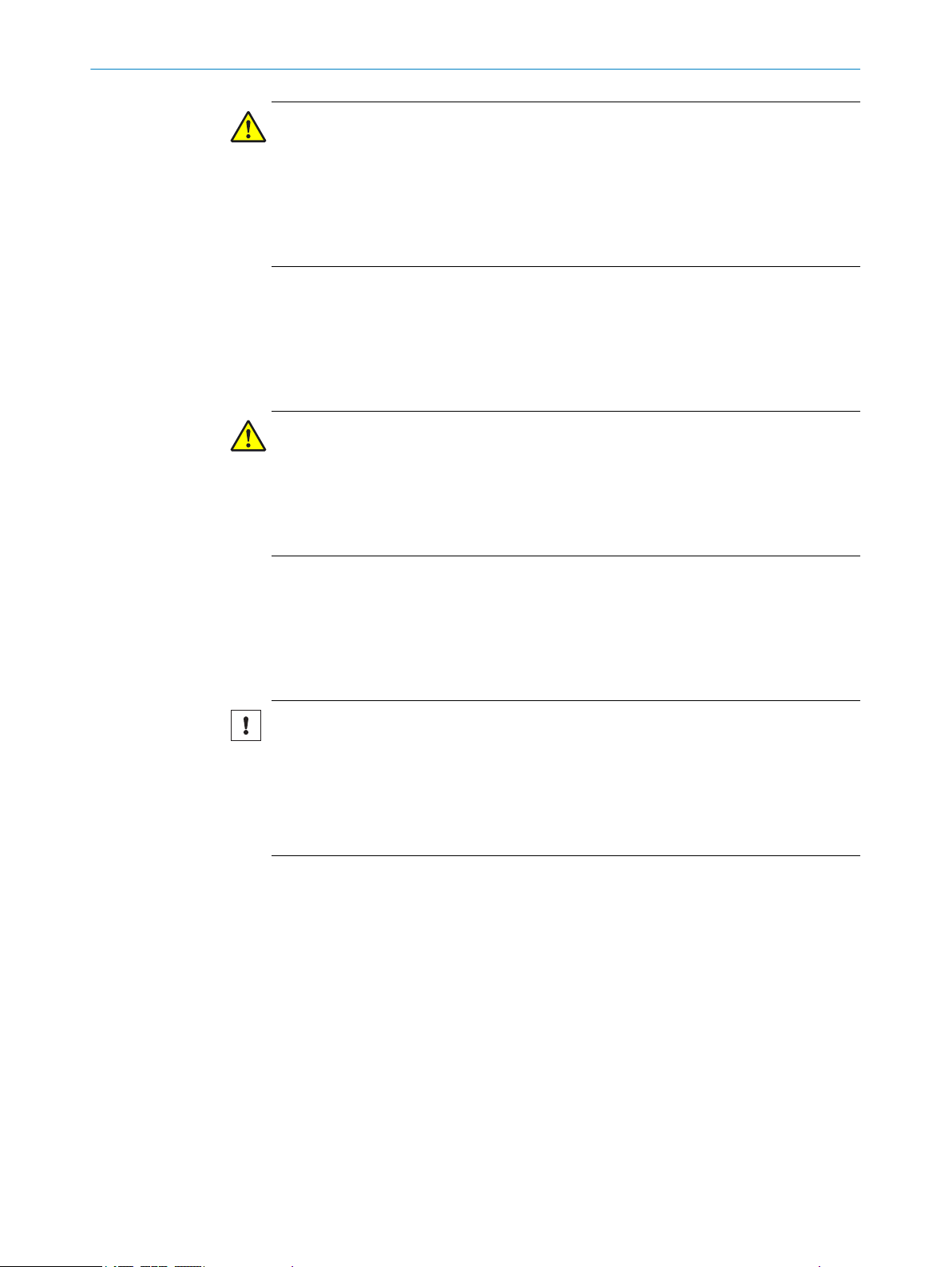
8.2 Actuating the emergency release
Approach
1. Ensure that actuators are not under tensile stress.
2. Turn the emergency release clockwise until it latches at the following symbol:
✓
The locking device is unlocked.
8023119/15LY/2019-10-28 | SICK O PE R AT I NG IN S TR U CT I ON S | TR110 Lock
Subject to change without notice
39
Page 40

8 OPERATION
Figure 38: Actuating the emergency release
Emergency release
1
Stop bolt
2
8.2.1 Moving the emergency release back after use
Approach
Push the stop bolt inward, e.g. with a small screwdriver.
b
Move the emergency release back to the following symbol:
b
Seal the emergency release.
b
Open the protective device and close it again.
b
✓
The safety locking device operates in normal mode again.
Carry out a functional test.
b
8.3 Actuating the escape release
Approach
1. Press the red button of the escape release as far as it goes.
✓
The locking device is unlocked.
40
O PE R AT I NG IN S TR U CT I ON S | TR110 Lock 8023119/15LY/2019-10-28 | SICK
Subject to change without notice
Page 41

Figure 39: Fluchtentriegelung betätigen
Red button of the escape release
1
OPERATION 8
8.3.1 Moving the escape release back after use
Approach
Pull the red button of the escape release back out.
b
Open the protective device and close it again.
b
✓
The safety locking device operates in normal mode again.
Carry out a functional test.
b
8023119/15LY/2019-10-28 | SICK O PE R AT I NG IN S TR U CT I ON S | TR110 Lock
Subject to change without notice
41
Page 42

9 TROUBLESHOOTING
9 Troubleshooting
9.1 Safety
DANGER
Hazard due to lack of effectiveness of the protective device
Persons and parts of the body to be protected may not be recognized in case of non-
observance.
Immediately shut the machine down if the behavior of the machine cannot be
b
clearly identified.
Immediately put the machine out of operation if you cannot clearly identify or allo‐
b
cate the fault and if you cannot safely remedy the fault.
Secure the machine so that it cannot switch on unintentionally.
b
DANGER
Hazard due to unexpected starting of the machine
When any work is taking place, use the protective device to secure the machine or
b
to ensure that the machine is not switched on unintentionally.
DANGER
Hazard due to lack of effectiveness of the protective device
Persons and parts of the body to be protected may not be recognized in case of non-
observance.
Do not do repair work on device components.
b
Do not make changes to or manipulate device components.
b
Apart from the procedures described in this document, the device components
b
must not be opened.
NOTE
Additional information on troubleshooting can be found at the responsible SICK sub‐
sidiary.
9.2 System status
Important information
NOTE
Displays other than those described here indicate an internal device fault. In this case, please contact your respon‐
sible SICK subsidiary.
Status indicators
Table 14: Status indicators
Outputs LED indicators Status
Door OSSDs AUX
LOCK
Self-test X OFF OFF OFF OFF
42
O PE R AT I NG IN S TR U CT I ON S | TR110 Lock 8023119/15LY/2019-10-28 | SICK
AUX
DOOR
AUX
DIA
STATE DIA LOCK
Ö5 Hz
10 s
o o
Self-test after switch-on
Subject to change without notice
Page 43

Outputs LED indicators Status
Door OSSDs AUX
LOCK
AUX
DOOR
AUX
DIA
Normal operation Closed ON ON ON OFF
Closed OFF OFF ON OFF
Open OFF OFF OFF OFF
Teach-in Open OFF OFF OFF OFF
Closed OFF X ON OFF
X OFF X X OFF
Error display X OFF X X ON
X OFF OFF OFF ON
X OFF OFF OFF ON
X OFF OFF OFF ON
X OFF X X ON
X OFF OFF OFF ON
STATE DIA LOCK
O o O
Ö 1 x
o o
inverse
Ö 1 × o o
Ö 3 × o o
Ö1 Hz o o
Ö Ö o
Ö 1 × O o
Ö 2 × O o
Ö 3 × O o
Ö 4 × O o
Ö 5 × O o
o O
X Internal error
TROUBLESHOOTING 9
Door closed and locked
Door closed and not
locked
Door open
Teach-in readiness
Teach-in process
Teach-in process suc‐
cessful
Error during teachin (actuator removed
from the response
range before the teach‐
ing operation ended or
defective actuator
detected)
Input error (e.g. missing
test pulses, non-logical
switching state of the
predecessor in the
switch chain)
Read error (e.g. actua‐
tor defective)
Error at output (e.g.
cross-circuit, loss of
switching capability)
Locked actuator
detected
8023119/15LY/2019-10-28 | SICK O PE R AT I NG IN S TR U CT I ON S | TR110 Lock
Subject to change without notice
43
Page 44

10 DECOMMISSIONING
10 Decommissioning
10.1 Disposal
Approach
Always dispose of unusable devices in accordance with national waste disposal
b
regulations.
Complementary information
SICK will be glad to help you dispose of these devices on request.
44
O PE R AT I NG IN S TR U CT I ON S | TR110 Lock 8023119/15LY/2019-10-28 | SICK
Subject to change without notice
Page 45

11 Technical data
11.1 Data sheet
Table 15: Features
Features
Sensor principle Transponder
Coding Uniquely coded
Locking force F
With straight TR110-XAS actuator 3,900 N (EN ISO 14119)
With angled TR110-XABT actuator 1,500 N (EN ISO 14119)
With TR110-XAFx hinged actuator 2,600 N (EN ISO 14119)
Retaining force FZh (FZh = F
With straight TR110-XAS actuator 300 N (EN ISO 14119)
With angled TR110-XABT actuator 1,100 N (EN ISO 14119)
With TR110-XAFx hinged actuator 2,000 N (EN ISO 14119)
Actuating force 10 N
Retaining force 20 N
Force against which unlocking is possible ≤ 20 N
Actuating frequency ≤ 0.5 Hz
Starting speed ≤ 20 m/min
Overrun 5 mm
max
max
TECHNICAL DATA 11
/1.3)
Table 16: Safety-related parameters
Safety-related parameters
Performance level
Category
1)
PFHd 2) (mean probability of a dangerous fail‐
1)
PL e (EN ISO 13849-1)
4 (EN ISO 13849-1)
4.1 × 10
–9
ure per hour)
TM (mission time) 20 years (EN ISO 13849–1)
Type Type 4 (EN ISO 14119)
Coding level High coding level (EN ISO 14119)
Safe status when a fault occurs At least one safety-related semiconductor out‐
put (OSSD) is in the OFF state.
1)
Applies to monitoring the door position (interlocking monitoring) and locking monitoring.
2)
The locking solenoid is externally controlled and so does not contribute to the probability of failure. The
safety level of the locking device controller is determined exclusively by the external controller.
Table 17: Electrical data
Electrical data
Classification based on cULus Class 2
Protection class III (IEC 61140)
Utilization category DC-13: 24 V, 150 mA (IEC 60947-5-2)
Supply voltage U
Safety switches
Locking solenoid
V
20.4 V DC … 27.6 V DC
1)
20.4 V DC … 26.4 V DC
Current consumption
8023119/15LY/2019-10-28 | SICK O PE R AT I NG IN S TR U CT I ON S | TR110 Lock
Subject to change without notice
45
Page 46

11 TECHNICAL DATA
Electrical data
Safety switches
Locking solenoid
Pushbutton (LED)
40 mA
400 mA
10 mA
Power consumption of locking solenoid 6 W
External device protection
Safety switches
Locking solenoid
2)
0.25 A … 2 A
0.5 A … 8 A
Switch-on time of locking solenoid 100%
Contamination rating 3 (EN 60947-1)
Power-up delay
All except for TR110-SRUCAxx
TR110-SRUCAxx
1 s
< 8 s
Response time ≤ 260 ms (+5 ms for each additional safety
locking device in a safe series connection)
Release time 400 ms
Discrepancy time ≤ 10 ms (EN IEC 60947-5-3)
Risk time
Dwell time between successive locking/unlock‐
3)
260 ms
2.5 s
ing procedures
Rated insulation voltage Ui 50 V DC (IEC 60947-1)
Rated impulse withstand voltage U
imp
500 V (IEC 60947-5-1)
Rated short-circuit current 100 A
Locking principle
TR110-SRxxxx
TR110-SLxxxx
1)
The locking solenoid of the TR110 Lock safety locking device is externally controlled and supplied with
power.
2)
Medium time-lag triggering characteristics.
3)
The risk time is the time needed to detect internal and external faults. External errors affect the OSSDs
(short-circuit to an OSSD and cross-circuit between the two OSSDs). At least one of the two OSSDs is
safely switched off during the risk time.
Closed-circuit current principle
Open-circuit current principle
Table 18: Interfaces
Interfaces
System connection
TR110-SxxSAxx
Male connector, M12, 8-pin, A-coded
TR110-SxxFLxx
TR110-SxxCAxx
TR110-Sxx2Bxx
Male connector, M12, 8-pin, A coded, and
male connector, M12, 5-pin, A coded
46
O PE R AT I NG IN S TR U CT I ON S | TR110 Lock 8023119/15LY/2019-10-28 | SICK
Subject to change without notice
Page 47

TECHNICAL DATA 11
Table 19: Outputs
Output data
Type of output
Safety outputs 2 semiconductor outputs (OSSDs), p-switching,
short-circuit protected
Application diagnostic outputs p-switching, short-circuit protected
Output current (OSSDs)
ON state
OFF state
Output voltage (OSSDs)
ON state
OFF state
Test pulse duration (OSSDs)
All except for TR110-SRUCAxx
TR110-SRUCAxx
Test pulse interval (OSSDs)
All except for TR110-SRUCAxx
TR110-SRUCAxx
Application diagnostic outputs
Output current
Output voltage
N/O contacts of the pushbuttons (only TR110-SXXXBXX)
Output current
Output voltage
1 mA … 150 mA
≤ 250 µA
Uv -1.5 V DC … U
0 V DC … 1 V DC
300 µs
1 ms
≤ 100 ms
≤ 140 ms
1 mA … 50 mA
0.8 × Uv … U
v
1 … 50 mA
U
v
v
Table 20: Mechanical data
Mechanical data
Dimensions (W x H x D) See "Safety switch dimensional drawings",
page 49
Material
Safety switch housing
Actuating head
Plug connector
Fiberglass-reinforced thermoplastic
Zinc die cast
Nickel-plated brass
Weight 0.42 kg
Mechanical service life 1 × 10⁶ switching operations
Table 21: Ambient data
Ambient data
Enclosure rating IP 67 (IEC 60529)
IP 69 (IEC 60529)
IP 69K (IEC 20653)
Enclosure rating of the variants with operating
IP 65 (IEC 60529)
buttons
Ambient operating temperature –20 °C … +55 °C
Vibration resistance EN IEC 60947-5-3
EMC EN IEC 60947-5-3
8023119/15LY/2019-10-28 | SICK O PE R AT I NG IN S TR U CT I ON S | TR110 Lock
Subject to change without notice
47
Page 48

11 TECHNICAL DATA
11.2 Connecting cables
Requirements for the connecting cables
Table 22: Requirements for the connecting cables
Parameter Value
Min. wire cross-section 0.25 mm²
R max. 60 Ohm/km
C max. 120 nF/km
L max. 0.65 mH/km
Recommended cable type = LIYY 8 x 0.25 mm² or 5 x 0.34 mm²
Maximum cable lengths
Table 23: Maximum cable lengths
Max. number of safety lock‐
ing devices
5 10 150
6 10 120
10 10 70
Possible output current per
OSSD (mA)
25 100
50 80
100 50
150 25
25 90
50 70
100 50
150 25
25 60
50 50
100 40
150 25
Max. length of cable from the
last safety locking device to
the controller (m)
48
O PE R AT I NG IN S TR U CT I ON S | TR110 Lock 8023119/15LY/2019-10-28 | SICK
Subject to change without notice
Page 49

11.3 Safety switch dimensional drawings
144
30
40
34
12
40 +5
5,3 (4x)
16
C
B
A
42
33
10
190
14
M12x1
41,5
37,5
12
0.5
0.5
TR110-SRUCA00 and TR110-SLUCA00 safety switches
TECHNICAL DATA
11
Figure 40: Dimensional drawing of TR110-SRUCA00 and TR110-SLUCA0000 safety switches (mm)
8023119/15LY/2019-10-28 | SICK O PE R AT I NG IN S TR U CT I ON S | TR110 Lock
Subject to change without notice
49
Page 50

M12x1
42
190
14
33
35
10
14
40
12
41,5
37,5 67,5
144
30
40
34 12
40 +5
5,3 (4x)
44/74/94
16
ca. 5
C
B
A
0.5
0.5
TECHNICAL DATA
11
TR110-SRUSA01 and TR110-SRUFL01 safety switches
Figure 41: Dimensional drawing of TR110-SRUSA01 and TR110-SRUFL0100 safety switches (mm)
50
O PE R AT I NG IN S TR U CT I ON S | TR110 Lock 8023119/15LY/2019-10-28 | SICK
Subject to change without notice
Page 51

TR110-SRUCA01 safety switch
190 14
M12x1
42
33
10
35
40
14
41,5
37,5
12
67,5
144
30
34
40
12
40 +5
5,3 (4x)
44 / 74 / 94
16
ca. 5
C
B
A
0.5
0.5
TECHNICAL DATA
11
Figure 42: Dimensional drawing of TR110-SRUCA0100 safety switch (mm)
8023119/15LY/2019-10-28 | SICK O PE R AT I NG IN S TR U CT I ON S | TR110 Lock
Subject to change without notice
51
Page 52

144
30
40
34 12
40 +5
5,3 (4x)
42
190 14
33
10
M12x1
41,5
37,5
12
16
C
B
A
0.5
0.5
TECHNICAL DATA
11
TR110-SRUFL00, TR110-SLUFL00, TR110-SRUSA00 and TR110-SLUSA00 safety switches
Figure 43: Dimensional drawing of TR110-SRUFL00, TR110-SLUFL00, TR110-SRUSA00 and TR110-SLUSA0000 safety
switches (mm)
52
O PE R AT I NG IN S TR U CT I ON S | TR110 Lock 8023119/15LY/2019-10-28 | SICK
Subject to change without notice
Page 53

TR110-SRU2B00 and TR110-SLU2B00 safety switches
144
30
40
34 12
40 +5
5,3
16
C
B
A
33
10
190 14
M12x1
56
46
41,5
37,5
12
0.5
0.5
TECHNICAL DATA
11
Figure 44: Dimensional drawing of TR110-SRU2B00 and TR110-SLU2B00 safety switches (mm)
8023119/15LY/2019-10-28 | SICK O PE R AT I NG IN S TR U CT I ON S | TR110 Lock
Subject to change without notice
53
Page 54

C
B
A
190
35
14
40
M12x1
14
56
46
10
33
41,5
37,5
67,5
12
30
40
144
34
40 +5
12
5,3 (4x)
44/74/94
16
ca. 5
0.5
0.5
TECHNICAL DATA
11
TR110-SRU2B01 safety switch
Figure 45: Dimensional drawing of TR110-SRU2B000 safety switch (mm)
54
O PE R AT I NG IN S TR U CT I ON S | TR110 Lock 8023119/15LY/2019-10-28 | SICK
Subject to change without notice
Page 55

11.4 Actuator dimensional drawings
17
20 11
18
30
4,4
18
45
8,5
2
2,5
9
R ≥300
R≥1400
R≥1200
16
A
A
0,5
29,5
37,5
4,4
20 35
+-4
1
max. 28
0,5
8,5
2
45 12,45
2,5
9
18
30
52
37,5
1,25
4,4
16
R≥300
0041≥R
R≥1200
16
A
A
0,5
4,4
8
35,5
max. 28
36
+-4
1
0,5
Straight actuator – TR110-XAS
TECHNICAL DATA
11
Figure 46: Dimensional drawing of TR110-XAS straight actua‐
tor (mm)
Figure 47: Min. door radii for TR110-XAS straight actuator
(mm)
Angled actuator – TR110-XABT
Figure 49: Min. door radii for TR110-XABT angled actuator
(mm)
Figure 48: Dimensional drawing of TR110-XABT angled actua‐
tor (mm)
8023119/15LY/2019-10-28 | SICK O PE R AT I NG IN S TR U CT I ON S | TR110 Lock
Subject to change without notice
55
Page 56

40
28
8,5
13,2
45
5,5
14
27
18
30
50
16
70°
16
0,5
20
R>200
max. 28
45
+-4
1
0,5
TECHNICAL DATA
11
Hinged actuators for top-hinged doors – TR110-XAFT
Figure 50: Dimensional drawing of TR110-XAFT hinged actuator (mm)
Figure 51: Min. door radii for TR110-XAFT
hinged actuator (mm)
56
O PE R AT I NG IN S TR U CT I ON S | TR110 Lock 8023119/15LY/2019-10-28 | SICK
Subject to change without notice
Page 57

Hinged actuators for bottom-hinged doors – TR110-XAFB
40
28
8,5
45
5,5
14
27
15,2
18
30
50
16
70°
16
0,5
7
max.28
R>200
45
+-4
1
0,5
TECHNICAL DATA
11
Figure 52: Dimensional drawing of TR110-XAFB hinged actuator (mm)
Figure 53: Min. door radii for TR110-XAFB
hinged actuator (mm)
8023119/15LY/2019-10-28 | SICK O PE R AT I NG IN S TR U CT I ON S | TR110 Lock
Subject to change without notice
57
Page 58

35
45
12
4
18
30
max. 23°
3,25
8,5
50
14
5,5
40
16
4
5,5
R≥200
40
0,5
33,5
1
max. 28
53
+-4
1
0,5
TECHNICAL DATA
11
Hinged actuators for left-hinged doors – TR110-XAFL
Figure 54: Dimensional drawing of TR110-XAFL hinged actuator (mm)
Figure 55: Min. door radius for TR110XAFL hinged actuator (mm)
58
O PE R AT I NG IN S TR U CT I ON S | TR110 Lock 8023119/15LY/2019-10-28 | SICK
Subject to change without notice
Page 59

Hinged actuators for right-hinged doors – TR110-XAFR
35 45
18
30
4 12
3,25
8,5
5,5
14
40
50
max. 23°
16
4
5,5
R≥200
40
0,5
33,5
1
max. 28
53
+-4
1
0,5
TECHNICAL DATA
11
Figure 56: Dimensional drawing of TR110-XAFR hinged actuator (mm)
Figure 57: Min. door radius for TR110XAFR hinged actuator (mm)
8023119/15LY/2019-10-28 | SICK O PE R AT I NG IN S TR U CT I ON S | TR110 Lock
Subject to change without notice
59
Page 60

83
45
4
180
M
5
21
91,5
21
6,5
35
TECHNICAL DATA
11
11.5 Dimensional drawings of the mounting bracket
Mounting bracket for safety locking device
Figure 58: Mounting bracket for safety locking device
60
O PE R AT I NG IN S TR U CT I ON S | TR110 Lock 8023119/15LY/2019-10-28 | SICK
Subject to change without notice
Page 61

Mounting bracket for actuator
43
46
4
42
6,5
14
25
56
TECHNICAL DATA
11
Figure 59: Mounting bracket for actuator
8023119/15LY/2019-10-28 | SICK O PE R AT I NG IN S TR U CT I ON S | TR110 Lock
Subject to change without notice
61
Page 62

12 ORDERING INFORMATION
12 Ordering information
12.1 Scope of delivery
Safety switches
•
Extension of the escape release (only for variants with escape release)
•
Safety note
•
Mounting instructions
•
Operating instructions for download: www.sick.com
•
12.2 Ordering information
Table 24: Ordering information, TR110 Lock
Locking principle Connection type Type code Part number
Power to release princi‐
ple
Power to release princi‐
ple
Power to release princi‐
ple
Power to release princi‐
plewith escape release
Power to release princi‐
plewith escape release
Power to release princi‐
plewith escape release
Power to lock principle M12 female connector (8-pin), straight TR110-SLUSA00 6034589
Power to lock principle M12 female connector (8-pin), straight, for connect‐
Power to lock principle M12 female connector (5-pin), straight
M12 female connector (8-pin), straight TR110-SRUSA00 6033743
M12 female connector (8-pin), straight, for connect‐
ing to a Flexi Loop
M12 female connector (5-pin), straight
M12 female connector (8-pin), straight
OSSDs cascadable with T-connector or in the con‐
trol cabinet
M12 female connector (8-pin), straight TR110-SRUSA01 6044631
M12 female connector (8-pin), straight, for connect‐
ing to a Flexi Loop
M12 female connector (5-pin), straight
M12 female connector (8-pin), straight
OSSDs cascadable with T-connector or in the con‐
trol cabinet
ing to a Flexi Loop
M12 female connector (8-pin), straight
OSSDs cascadable with T-connector or in the con‐
trol cabinet
TR110-SRUFL00 6044632
TR110-SRUCA00 6044635
TR110-SRUFL01 6044634
TR110-SRUCA01 6068075
TR110-SLUFL00 6044633
TR110-SLUCA00 6051481
Table 25: Ordering information, TR110 Lock with pushbuttons
Locking principle Connection type Type code Part number
Power to release princi‐
ple
Power to release princi‐
plewith emergency
release
Power to lock principle M12 female connector (5-pin), straight
62
O PE R AT I NG IN S TR U CT I ON S | TR110 Lock 8023119/15LY/2019-10-28 | SICK
M12 female connector (5-pin), straight
M12 female connector (8-pin), straight
M12 female connector (5-pin), straight
M12 female connector (8-pin), straight
M12 female connector (8-pin), straight
TR110-SRU2B00 6068076
TR110-SRU2B01 6068078
TR110-SLU2B00 6068077
Subject to change without notice
Page 63

13 Accessories
13.1 Actuator
TR110 Lock actuator
Table 26: Actuator
Description Type code Part number
Actuator, straight TR110-XAS 5321176
Actuator, angled TR110-XABT 5334663
Hinged actuators for top-hinged doors TR110-XAFT 5338336
Hinged actuators for bottom-hinged doors TR110-XAFB 5338338
Hinged actuators for left-hinged doors TR110-XAFL 5338331
Hinged actuators for right-hinged doors TR110-XAFR 5338332
Complementary information
•
•
ACCESSORIES 13
The straight actuators and angled actuators are provided with 2 × M4 retaining
screws.
The hinged actuators are provided with 2 × M5 retaining screws.
13.2 Connectivity
M12 connecting cable, 5-pin (0.34 mm2)
Table 27: Ordering information for M12 connecting cable, 5-pin (0.34 mm2)
Part Type code Part number
Female connector, straight, 2 m cable, flying
leads
Female connector, straight, 5 m cable, flying
leads
Female connector, straight, 10 m cable, flying
leads
Female connector, straight, 15 m cable, flying
leads
Female connector, straight, 20 m cable, flying
leads
Female connector, straight, 30 m cable, flying
leads
Female connector, angled, 2 m cable, flying
leads
Female connector, angled, 5 m cable, flying
leads
Female connector, angled, 10 m cable, flying
leads
YF2A15-020UB5XLEAX 2095617
YF2A15-050UB5XLEAX 2095618
YF2A15-100UB5XLEAX 2095619
YF2A15-150UB5XLEAX 2095620
YF2A15-200UB5XLEAX 2095614
YF2A15-300UB5XLEAX 2095621
YG2A15-020UB5XLEAX 2095772
YG2A15-050UB5XLEAX 2095773
YG2A15-100UB5XLEAX 2095774
1)
M12 connecting cable, 8-pin (0.25 mm2)
Table 28: Ordering information for M12 connecting cable, 8-pin (0.25 mm2)
Part Type code Part number
Female connector, straight, 2.5 m cable, flying
leads
1)
Ambient operating temperature: Down to −30° C with fixed installation.
2)
Ambient operating temperature: Down to -30°C with fixed installation.
8023119/15LY/2019-10-28 | SICK O PE R AT I NG IN S TR U CT I ON S | TR110 Lock
Subject to change without notice
YF2A18-025UA5XLEAX 2099229
2)
63
Page 64

13 ACCESSORIES
Part Type code Part number
Female connector, straight, 5 m cable, flying
YF2A18-050UA5XLEAX 2095653
leads
Female connector, straight, 7.5 m cable, flying
YF2A18-075UA5XLEAX 2099230
leads
Female connector, straight, 10 m cable, flying
YF2A18-100UA5XLEAX 2095654
leads
Female connector, straight, 15 m cable, flying
YF2A18-150UA5XLEAX 2095679
leads
Female connector, straight, 20 m cable, flying
YF2A18-200UA5XLEAX 2095680
leads
Female connector, straight, 30 m cable, flying
YF2A18-300UA5XLEAX 2095681
leads
Female connector, angled, 2 m cable, flying
YG2A18-020UA5XLEAX 2095779
leads
Female connector, angled, 5 m cable, flying
YG2A18-050UA5XLEAX 2095780
leads
Female connector, angled, 10 m cable, flying
YG2A18-100UA5XLEAX 2095781
leads
M12 connection cable, 5-pin (0.34 mm2)
Table 29: Ordering information for M12 connection cable, 5-pin (0.34 mm2)
Part Type code Part number
Female connector, straight, 0.6 m cable, male
YF2A15-C60UB5M2A15 2096006
connector, straight
Female connector, straight, 1 m cable, male
YF2A15-010UB5M2A15 2096007
connector, straight
Female connector, straight, 2 m cable, male
YF2A15-020UB5M2A15 2096009
connector, straight
Female connector, straight, 5 m cable, male
YF2A15-050UB5M2A15 2096010
connector, straight
Female connector, straight, 10 m cable, male
YF2A15-100UB5M2A15 2096011
connector, straight
Female connector, straight, 15 m cable, male
YF2A15-100UB5M2A15 2096171
connector, straight
3)
M12 connection cable, 8-pin (0.25 mm2)
Table 30: Ordering information for M12 connection cable, 8-pin (0.25 mm2)
Part Type code Part number
Female connector, straight, 0.6 m cable,
YF2A18-C60UA5M2A18 2096031
straight male connector
Female connector, straight, 1 m cable, straight
YF2A18-010UA5M2A18 2096032
male connector
Female connector, straight, 20 m cable,
YF2A18-020UA5M2A18 2096033
straight male connector
Female connector, straight, 1 m cable, straight
YF2A18-050UA5M2A18 2096034
male connector
Female connector, straight, 10 m cable,
YF2A18-100UA5M2A18 2096035
straight male connector
4)
3)
Ambient operating temperature: Down to -30 °C with fixed installation.
4)
Ambient operating temperature: Down to −30° C with fixed installation.
64
O PE R AT I NG IN S TR U CT I ON S | TR110 Lock 8023119/15LY/2019-10-28 | SICK
Subject to change without notice
Page 65

Distributor
Table 31: Ordering information for distributor
Part Type code Part number
T-connector STR1-XXA 5339609
Terminator plug
Table 32: Ordering information for terminator plug
Part Type code Part number
End connector for series connection MLP1-XXT 1078201
13.3 Additional accessories
Table 33: Additional accessories
Description Type code Part number
Emergency release TR110-XER 5338333
Safety switch mounting plate, angled TR110-XMSB 5338334
Actuator mounting plate, angled TR110-XMAB 5338335
Cover cap set, unprinted, 5 colors TR110-XTC 5339045
ACCESSORIES 13
8023119/15LY/2019-10-28 | SICK O PE R AT I NG IN S TR U CT I ON S | TR110 Lock
Subject to change without notice
65
Page 66

14 ANNEX
14 Annex
14.1 Compliance with EU directives
TR110 Lock, Safety locking device
SICK AG, Erwin-Sick-Strasse 1, D-79183 Waldkirch, Germany
You can find the EU declaration of conformity and the current operating instructions by
entering the part number in the search field at www.sick.com (for the part number, see
the type label entry in the “Ident. no.” field).
Direct link to EU declaration of conformity: www.sick.com/9298268
The undersigned, representing the manufacturer, herewith declares that the product is
in conformity with the provisions of the following EU directive(s) (including all applicable
amendments), and that the standards and/or technical specifications stated in the EU
declaration of conformity have been used as a basis for this.
MACHINERY DIRECTIVE 2006/42/EC
•
RE DIRECTIVE 2014/53/EU
•
ROHS DIRECTIVE 2011/65/EU
•
Waldkirch: 2019-01-03
ppa. Walter Reithofer
Vice President R & D
(GBC Industrial Safety)
authorized for technical documentation
ppa. Birgit Knobloch
Vice President Operations
(GBC Industrial Safety)
66
O PE R AT I NG IN S TR U CT I ON S | TR110 Lock 8023119/15LY/2019-10-28 | SICK
Subject to change without notice
Page 67

ANNEX 14
8023119/15LY/2019-10-28 | SICK O PE R AT I NG IN S TR U CT I ON S | TR110 Lock
Subject to change without notice
67
Page 68

Detailed addresses and further locations at www.sick.com
Australia
Phone +61 (3) 9457 0600
1800 33 48 02 – tollfree
E-Mail sales@sick.com.au
Austria
Phone +43 (0) 2236 62288-0
E-Mail office@sick.at
Belgium/Luxembourg
Phone +32 (0) 2 466 55 66
E-Mail info@sick.be
Brazil
Phone +55 11 3215-4900
E-Mail comercial@sick.com.br
Canada
Phone +1 905.771.1444
E-Mail cs.canada@sick.com
Czech Republic
Phone +420 234 719 500
E-Mail sick@sick.cz
Chile
Phone +56 (2) 2274 7430
E-Mail chile@sick.com
China
Phone +86 20 2882 3600
E-Mail info.china@sick.net.cn
Denmark
Phone +45 45 82 64 00
E-Mail sick@sick.dk
Finland
Phone +358-9-25 15 800
E-Mail sick@sick.fi
France
Phone +33 1 64 62 35 00
E-Mail info@sick.fr
Germany
Phone +49 (0) 2 11 53 010
E-Mail info@sick.de
Greece
Phone +30 210 6825100
E-Mail office@sick.com.gr
Hong Kong
Phone +852 2153 6300
E-Mail ghk@sick.com.hk
Hungary
Phone +36 1 371 2680
E-Mail ertekesites@sick.hu
India
Phone +91-22-6119 8900
E-Mail info@sick-india.com
Israel
Phone +972 97110 11
E-Mail info@sick-sensors.com
Italy
Phone +39 02 27 43 41
E-Mail info@sick.it
Japan
Phone +81 3 5309 2112
E-Mail support@sick.jp
Malaysia
Phone +603-8080 7425
E-Mail enquiry.my@sick.com
Mexico
Phone +52 (472) 748 9451
E-Mail mexico@sick.com
Netherlands
Phone +31 (0) 30 229 25 44
E-Mail info@sick.nl
New Zealand
Phone +64 9 415 0459
0800 222 278 – tollfree
E-Mail sales@sick.co.nz
Norway
Phone +47 67 81 50 00
E-Mail sick@sick.no
Poland
Phone +48 22 539 41 00
E-Mail info@sick.pl
Romania
Phone +40 356-17 11 20
E-Mail office@sick.ro
Russia
Phone +7 495 283 09 90
E-Mail info@sick.ru
Singapore
Phone +65 6744 3732
E-Mail sales.gsg@sick.com
Slovakia
Phone +421 482 901 201
E-Mail mail@sick-sk.sk
Slovenia
Phone +386 591 78849
E-Mail office@sick.si
South Africa
Phone +27 10 060 0550
E-Mail info@sickautomation.co.za
South Korea
Phone +82 2 786 6321/4
E-Mail infokorea@sick.com
Spain
Phone +34 93 480 31 00
E-Mail info@sick.es
Sweden
Phone +46 10 110 10 00
E-Mail info@sick.se
Switzerland
Phone +41 41 619 29 39
E-Mail contact@sick.ch
Taiwan
Phone +886-2-2375-6288
E-Mail sales@sick.com.tw
Thailand
Phone +66 2 645 0009
E-Mail marcom.th@sick.com
Turkey
Phone +90 (216) 528 50 00
E-Mail info@sick.com.tr
United Arab Emirates
Phone +971 (0) 4 88 65 878
E-Mail contact@sick.ae
United Kingdom
Phone +44 (0)17278 31121
E-Mail info@sick.co.uk
USA
Phone +1 800.325.7425
E-Mail info@sick.com
Vietnam
Phone +65 6744 3732
E-Mail sales
.gsg@sick.com
8023119/15LY/2019-10-28/en
SICK AG | Waldkirch | Germany | www.sick.com
 Loading...