

Page 1

TR10 Lock
Safety locking device
O P E R A T I N G I N S T R U C T I O N S
Page 2

Described product
TR10 Lock
Manuf
acturer
SICK A
G
Erwin-Sick-Str. 1
79183 Waldkirch
Germany
Legal information
This wor
k is protected by copyright. Any rights derived from the copyright shall be
reserved for SICK AG. Reproduction of this document or parts of this document is only
permissible within the limits of the legal determination of Copyright Law. Any modifica‐
tion, abridgment or translation of this document is prohibited without the express writ‐
ten permission of SICK AG.
The trademarks stated in this document are the property of their respective owner.
© SICK AG. All rights reserved.
Original document
This document is an or
iginal document of SIC
K AG.
2
O PE R AT I NG IN S TR U CT I ON S | TR10 Lock 8019972/2016-07-19 | SICK
Subject to change without notice
Page 3

Contents
CONTENTS
1 About this document........................................................................ 5
1.1 Function of this document....................................................................... 5
1.2 Scope......................................................................................................... 5
1.3 Additional information.............................................................................. 5
1.4 Symbols and document conventions...................................................... 5
2 Safety information............................................................................ 7
2.1 General safety notes................................................................................. 7
2.2 Intended use............................................................................................. 7
2.3 Requirements for the qualification of personnel.................................... 7
3 Product description........................................................................... 8
3.1 Setup and function................................................................................... 8
3.2 Product characteristics............................................................................. 8
3.3 Manual deactivation................................................................................. 9
4 Project planning................................................................................ 11
4.1 Manufacturer of the machine.................................................................. 11
4.2 Operator of the machine.......................................................................... 11
4.3 Assembly................................................................................................... 12
4.4 Integrating into the electrical control...................................................... 13
4.5 Testing plan............................................................................................... 16
5 Mounting............................................................................................. 17
5.1 Safety......................................................................................................... 17
5.2 Installation................................................................................................ 17
6 Electrical installation........................................................................ 21
6.1 Safety......................................................................................................... 21
6.2 Notes on cULus......................................................................................... 21
6.3 Device connection (M12, 8-pin).............................................................. 21
6.4 Device connection (flying lead)................................................................ 22
6.5 Connecting a cascade.............................................................................. 22
7 Commissioning.................................................................................. 25
7.1 Switching on.............................................................................................. 25
7.2 Teach-in..................................................................................................... 25
7.3 Testing....................................................................................................... 26
8 Troubleshooting................................................................................. 27
8.1 Safety......................................................................................................... 27
8.2 Diagnostic LEDs........................................................................................ 27
9 Technical data.................................................................................... 30
9.1 Technical data........................................................................................... 30
8019972/2016-07-19 | SICK OP E RA T IN G I N ST R UC T IO N S | TR10 Lock
Subject to change without notice
3
Page 4

CONTENTS
9.2 Response time.......................................................................................... 32
9.3 Course of the output signal switching device test over time................. 32
9.4 Dimensional drawings.............................................................................. 33
10 Ordering information........................................................................ 35
10.1 Scope of delivery...................................................................................... 35
10.2 Ordering information for TR10 Lock........................................................ 35
11 Accessories........................................................................................ 36
11.1 Actuator..................................................................................................... 36
11.2 Connectivity............................................................................................... 36
11.3 Mounting bracket...................................................................................... 38
11.4 Mounting accessories.............................................................................. 38
12 Annex.................................................................................................. 39
12.1 Compliance with EU directives................................................................. 39
12.2 FCC and IC radio approval........................................................................ 40
4
O PE R AT I NG IN S TR U CT I ON S | TR10 Lock 8019972/2016-07-19 | SICK
Subject to change without notice
Page 5
1 About this document
1.1 Function of this document
These operating instructions contain the information needed during the life cycle of the
ty locking device.
safe
These operating instructions must be made available to all people who work with the
safety locking device.
1.2 Scope
These operating instructions only apply to the TR10 Lock safety locking device.
1.3 Additional information
www.sick.com
ABOUT THIS DOCUMENT 1
The f
•
•
•
•
•
wing information is available on the Internet:
ollo
versions in other languages
data sheets and application examples
CAD data of drawings and dimensional drawings
certificates (e.g. EU declaration of conformity)
Guide for Safe Machinery (Six steps to a safe machine)
1.4 Symbols and document conventions
The following symbols and conventions are used in this document:
Safety notes and other notes
DANGER
Indicates a situation pr
injuries if not prevented.
WARNING
Indicates a situation presenting possible danger, which may lead to death or serious
injuries if not prevented.
CAUTION
Indicates a situation pr
injuries if not prevented.
esenting imminent danger, which will lead to death or serious
esenting possible danger, which may lead to moderate or minor
NOTICE
Indicates a situation pr
not prevented.
NOTE
Indicates useful tips and r
Instructions to action
r
The ar
b
8019972/2016-07-19 | SICK OP E RA T IN G I N ST R UC T IO N S | TR10 Lock
Subject to change without notice
ow denotes instructions to action.
esenting possible danger, which may lead to property damage if
ecommendations.
5
Page 6

1 ABOUT THIS DOCUMENT
1. The sequence of instructions for action is numbered.
2. F
✓
LED symbols
These symbols indicate the status of an LED:
Terminology
Dang
A dangerous state is a status of the machine or facility, where people may be injured.
Protective devices prevent this risk if the machine is operated within its intended use.
The figures in this document always show the dangerous state of the machine as move‐
ment of a machine part. In practice, there are different dangerous states, such as:
•
•
•
•
ollow the order in which the numbered instructions are given.
The check mark denotes the result of an instruction.
The LED is off.
The LED is flashing.
The LED is illuminated continuously.
er
ous state
Machine movements
Electrical parts
Visible and invisible beam
A combination of multiple hazards
6
O PE R AT I NG IN S TR U CT I ON S | TR10 Lock 8019972/2016-07-19 | SICK
Subject to change without notice
Page 7

2 Safety information
2.1 General safety notes
The safety locking device must be configured and operated correctly by qualified safety
personnel accor
2.2 Intended use
When used in conjunction with a movable physical guard and the machine controller,
the saf
ety locking device prevents the protective device from being opened while a dan‐
gerous machine function is being executed.
The safety locking device may only be used on the machine on which it was configured,
mounted, installed, and commissioned by qualified safety personnel in accordance with
these operating instructions.
Incorrect use, improper modification of or tampering with the safety locking device will
invalidate any warranty from SICK AG; in addition, any responsibility and liability of SICK
AG for damage and secondary damage caused by this is excluded.
NOTE
The safety locking device is also suitable for process protection.
SAFETY INFORMATION 2
ding to the machine requirements.
2.3 Requirements for the qualification of personnel
The safety locking device must be configured, installed, connected, commissioned, and
serviced onl
Project planning
For project planning, a person is considered competent when he/she has expertise and
experience in the selection and use of protective devices on machines and is familiar
with the relevant technical rules and national work safety regulations.
Mechanical mounting, electrical installation, and commissioning
For the task, a person is considered qualified when he/she has the expertise and expe‐
rience in the relevant field and is sufficiently familiar with the application of the protec‐
tive device on the machine to be able to assess whether it is in an operationally safe
state.
Operation and maintenance
For operation and maintenance, a person is considered competent when he/she has
the expertise and experience in the relevant field and is sufficiently familiar with the
application of the protective device on the machine and has been instructed by the
machine operator in its operation.
y by qualified safety personnel.
8019972/2016-07-19 | SICK OP E RA T IN G I N ST R UC T IO N S | TR10 Lock
Subject to change without notice
7
Page 8

3 PRODUCT DESCRIPTION
3 Product description
3.1 Setup and function
The safety locking device is an interlocking device with a lock consisting of a non-con‐
tact saf
either has a low (universally coded) or high (unique coded) coding level.
When the protective device is closed, the actuator is guided to the safety switch. When
the actuation field is reached, the actuator code is read and analyzed via RFID. If the
code is valid, the application diagnostic output switches. When the locking command is
active, the guard locking pin is extended. If the guard locking pin is detected in the
actuator, the locking process has been successful and the safe output signal switching
devices (OSSD) are switched.
The safety locking device can only be locked when the protective device is closed.
The guard locking pin is actuated by a bistable solenoid. This means that the safety
locking device consumes little electricity and does not produce any heat. Nevertheless,
the function of a safety locking device is executed via the electronics according to the
“power to release” or “power to lock” principle.
ety switch and a coded actuator. Depending on the product variant, the actuator
3.2 Product characteristics
3.2.1 Product variants
The safety locking device is delivered in different variants. An overview of important dis‐
tinguishing f
Designed according to “power to release” or “power to lock” principle
•
Versions for universally coded or unique coded actuators
•
Cable with M12 plug connector (0.2 m) or flying leads (3 or 10 m)
•
Complete overview of all variants: see "Ordering information for TR10 Lock", page 35
Variant according to “power to release” principle
Activ
•
Deactivate lock: voltage at lock input
•
When the voltage at the lock input is interrupted, the lock remains activated and the
protective device cannot be opened immediately.
Variant according to “power to lock” principle
Activ
•
Deactivate lock: no voltage at lock input
•
When the voltage is interrupted, the lock is deactivated and the protective device can
be opened immediately.
eatures between the variants is provided below.
ate lock: no voltage at lock input
ate lock: voltage at lock input
DANGER
Hazard due t
If the voltage drops, the safety locking device deactivates regardless of whether the
dangerous state of the machine has ended
Assess the accident risk. The device must be configured correctly in order to be
b
used for protection of personnel.
Variant for universally coded actuators
All univer
8
O PE R AT I NG IN S TR U CT I ON S | TR10 Lock 8019972/2016-07-19 | SICK
o lack of effectiveness of the protective device
sally coded actuators are accepted. No teach-in is required.
Subject to change without notice
Page 9

Variant for unique coded actuators
PRODUCT DESCRIPTION 3
A unique coded actuat
can be taught in one after another. Only the most recently taught-in actuator is valid.
When teaching in an actuator, the safety locking device can be permanently coded
(optional). If the safety locking device is permanently coded, no further actuators can
be taught in. This cannot be undone.
3.2.2 OSSD
Output signal switching device: signal output for the protective device, which is used for
s
opping the dangerous movement.
t
An OSSD is a safety switching output. The functionality of each OSSD is tested periodi‐
cally. OSSDs are always connected in pairs and must undergo dual-channel analysis for
safety reasons. An OSSD pair is formed from two OSSDs that are connected and ana‐
lyzed together.
3.3 Manual deactivation
In some situations, it may be necessary to deactivate the lock manually (e.g., in the
e
ent of faults). A functional test must be carried out after the lock has been deacti‐
v
vated.
Mechanical unlocking mechanism
In the event of functional faults, the safety locking device can be deactivated with the
mechanical unlocking mechanism regardless of the state of the electromagnet. The
mechanical unlocking mechanism is not suitable for emergency release or escape
release.
or must be taught in during commissioning. Up to 8 actuators
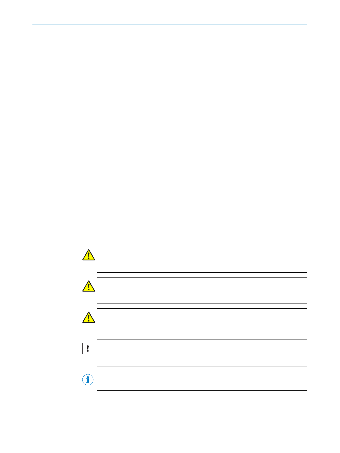
When the mechanical unlocking mechanism is actuated, the lock is deactivated and
the OSSDs switch off. This must generate a stop command.
Actuating the mechanical unlocking mechanism
Guide a scre
b
wdriver with a max. diameter of 2.5 mm through the actuator and
push the guard locking pin into the safety locking device.
✓
The lock is deactivated. The safety locking device switches to the fault state (DIAG
light emitting diodes flash red).
After using the mechanical unlocking mechanism, disconnect the voltage supply from
the safety locking device and then reconnect. The safety locking device restarts.
8019972/2016-07-19 | SICK OP E RA T IN G I N ST R UC T IO N S | TR10 Lock
Subject to change without notice
9
Page 10
< 2,5
3 PRODUCT DESCRIPTION
Figure 1: Mechanical unlocking mechanism
10
O PE R AT I NG IN S TR U CT I ON S | TR10 Lock 8019972/2016-07-19 | SICK
Subject to change without notice
Page 11

4 Project planning
4.1 Manufacturer of the machine
DANGER
Failur
e to comply with manufacturer’s obligations
Hazard due to lack of effectiveness of the protective device
Carry out a risk assessment before using the safety locking device.
b
Do not tamper with, open, or modify the components of the safety locking device.
b
Make sure that the safety locking device is only repaired by the manufacturer or by
b
someone authorized by the manufacturer. Improper repair can lead to a loss of the
protective function.
Make sure that switch-on commands which bring about a dangerous state of the
b
machine are not enabled until the protective device is closed and the lock is acti‐
vated.
Make sure that the lock is not deactivated until the dangerous state of the
b
machine has stopped.
Make sure that closing a protective device and activating the lock does not cause
b
a dangerous machine function to start by itself. This must be controlled by a sepa‐
rate start command.
The safety locking device must not be bypassed (contacts jumpered), turned away,
b
removed, or rendered ineffective in any other way. Take measures to reduce
bypassing options as necessary.
PROJECT PLANNING 4
The safety locking device is designed in such a way as to eliminate internal faults
according t
Observe EN ISO 14119 on the use of interlocking devices in conjunction with physical
guards.
o ISO 13849–2, Table A4.
4.2 Operator of the machine
DANGER
e to observe operator obligations
Failur
Hazard due to lack of effectiveness of the protective device
Changes to the machine and changes to the mechanical mounting of the safety
b
locking device necessitate a new risk assessment. The results of this risk assess‐
ment may require the operator of the machine to meet a manufacturer’s obliga‐
tions.
Apart from the procedures described in this document, the components of the
b
safety locking device must not be opened or modified.
Do not carry out any repair work on components. Improper repair of the safety
b
locking device can lead to a loss of the protective function.
Make sure that replacement actuators are not used for bypassing. Restrict access
b
to actuators.
8019972/2016-07-19 | SICK OP E RA T IN G I N ST R UC T IO N S | TR10 Lock
Subject to change without notice
11
Page 12
421 3
4 PROJECT PLANNING
4.3 Assembly
DANGER
Bypassing the pr
otective device
Hazard due to lack of effectiveness of the protective device
Prevent any incentives to tamper with the safety locking device; for example, with
b
the following measures:
Variant for universally coded actuators only:
Co
er the safety switch and the actuator with additional equipment or protect
°
v
them against access.
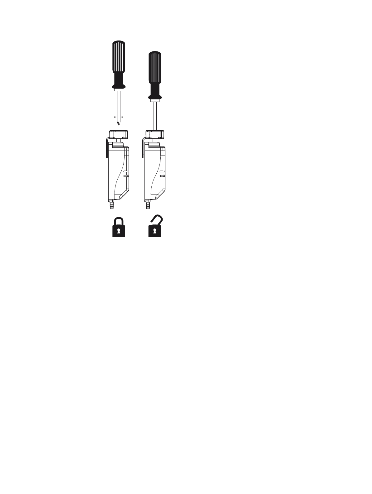
Actuation direction
The safe
ty locking device can be actuated from all 4 horizontal directions. The lock only
locks in the actuation direction, i.e., to the side.
Figure 2: Possible actuation directions
From front
From left
From rear
From right
The safety locking device is not suitable for vertical actuation. The lock does not pre‐
vent the actuator being moved upward out of the response range.
12
Figure 3: No vertical lock
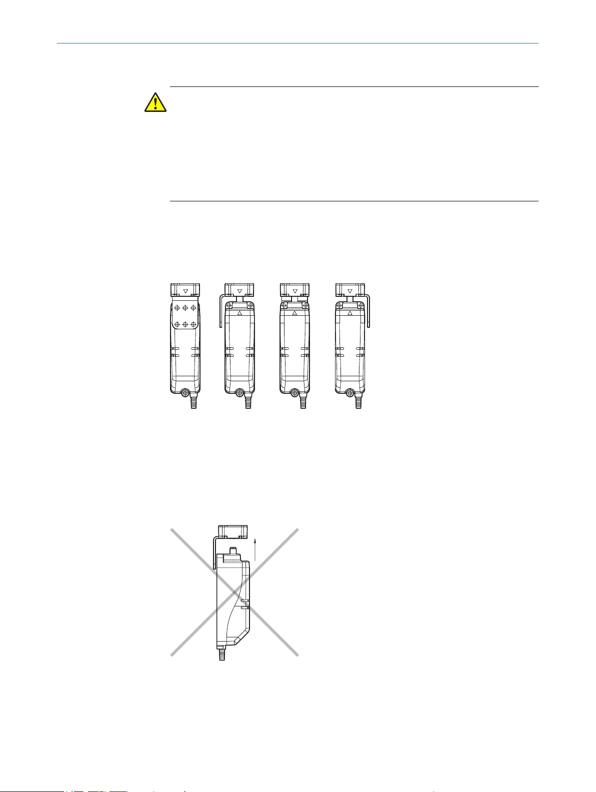
Distance
If multiple safe
at least 120 mm apart.
O PE R AT I NG IN S TR U CT I ON S | TR10 Lock 8019972/2016-07-19 | SICK
ty locking devices are mounted on the machine, they must be mounted
Subject to change without notice
Page 13
120
120
Figure 4: Min. distance for multiple safety switches
PROJECT PLANNING 4
Alignment
The safe
Figure 5: Possible alignment of the safety locking device
ty locking device can be mounted in any alignment.
4.4 Integrating into the electrical control
Switch-on commands which bring about a dangerous state of the machine must not be
4.4.1 Lock
enabled until the pr
not be deactivated until the dangerous state has ended. Depending on the safety con‐
cept, the signal is analyzed by, e.g., safety relays or a safety controller.
otective device is closed and the lock is activated. The lock must
The logic to generate a locking command with the control changes depending on the
pr
oduct v
Variant according to “power to release” principle
ariant selected.
To lock, make sure there is no voltage at the “lock input” contact (locking command
active).
To unlock, apply 24 V DC voltage at the “lock input” contact (locking command inac‐
tive).
For variants according to “power to lock” principle
8019972/2016-07-19 | SICK OP E RA T IN G I N ST R UC T IO N S | TR10 Lock
Subject to change without notice
13
Page 14
4 PROJECT PLANNING
To lock, apply 24 V DC voltage at the “lock input” contact (locking command active).
4.4.2 OSSDs
To unloc
k, make sure there is no voltage at the “lock input” contact (locking command
inactive).
Safety locking devices with local inputs and outputs can be directly integrated into the
mac
hine contr
oller.
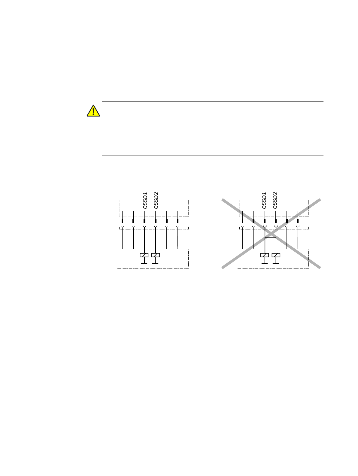
DANGER
Hazard due t
o lack of effectiveness of the protective device
In the case of non-compliance, it is possible that the dangerous state of the machine
may not be stopped or not stopped in a timely manner.
Make sure that the following control and electrical requirements are met so the
b
protective function can be fulfilled.
The output signals from an OSSD pair mus
•
In the machine controller, both signals from an OSSD pair must be processed sep‐
•
t not be connected to each other.
arately.
Figure 6: Dual-channel and isolated connection of OSSD 1 and OSSD 2
The machine mus
•
t switch to the safe state at any time if at least one OSSD in an
OSSD pair switches to the OFF state.
14
O PE R AT I NG IN S TR U CT I ON S | TR10 Lock 8019972/2016-07-19 | SICK
Subject to change without notice
Page 15

PROJECT PLANNING 4
vent the formation of a potential difference between the load and the protec‐
Pre
•
tive device. If you connect loads to the OSSDs (safety outputs) that also switch if
controlled with negative voltage (e.g., electro-mechanical contactor without
reverse polarity protection diode), you must connect the 0 V connections of these
loads and those of the corresponding protective device individually and directly to
the same 0 V terminal strip. In the event of a fault, this is the only way to ensure
that there can be no potential difference between the 0 V connections of the loads
and those of the corresponding protective device.
Figure 7: No potential difference between load and protective device
DANGER
Hazard due t
o lack of effectiveness of the protective device
In the case of non-compliance, it is possible that the dangerous state of the machine
may not be stopped or not stopped in a timely manner.
Downstream contactors must be positively guided and monitored depending on appli‐
cable national regulations or required reliability of the safety function.
Make sure that downstream contactors are monitored (external device monitoring,
b
EDM).
Requirements for the electrical control of the machine
The OSSDs ar
e shor
device is locked, the OSSDs signal the ON state with the HIGH signal level (non-iso‐
lated). If the safety locking device is unlocked or there is a device fault, the OSSDs sig‐
nal the OFF state with the LOW signal level.
4.4.3 Application diagnostic output
The application diagnostic output signal changes as soon as the actuator is moved into
or lea
es the response range of the safety switch. In other words, it does so when the
v
moving protective device is opened and closed. This is not a safety output.
Actuator Application diagnostic output
Actuator not in response range. ON
Actuator in response range. OFF
Table 1: Application diagnostic output switching behavior
t-circuit protected to 24 V DC and 0 V. When the safety locking
4.4.4 Cascading
Cascading can be used to connect multiple safety locking devices. The connected devi‐
ces will pr
vide the combined safety outputs and therefore act outwardly like one
o
device.
8019972/2016-07-19 | SICK OP E RA T IN G I N ST R UC T IO N S | TR10 Lock
Subject to change without notice
15
Page 16

2
8
4
7
3
5
6
1
OSSD1
OSSD2
OSSD1
OSSD2
OSSD1
OSSD2
OSSD1
OSSD2
OSSD1
OSSD2
2
8
4
7
3
5
6
1
2
8
4
7
3
5
6
1
2
8
4
7
3
5
6
1
2
8
4
7
3
5
6
1
24 V DC
0 V DC
1
// ///
1
1
1 1
2
4 PROJECT PLANNING
TR10 Lock
Safe evaluation unit
The maximum number of safety locking devices depends on the following factors:
y v
Suppl
•
Length of cables used
•
Cross-section of cables used
•
Load current
•
oltage applied
The voltage drop in the cascade must be checked to ensure that the defined minimum
voltage is still present at the last safety locking device.
4.5 Testing plan
The number of safety locking devices in a cascade affects the response time of the sys‐
tem (see "Response time", page 32).
The cascade can be implemented via special T-connectors and an end connector (see
"Connecting a cascade", page 22).
NOTE
In the case of saf
ety switches cascaded using T-connectors, it is not possible to evalu‐
ate the application diagnostic output.
The safety locking device must be tested by appropriately qualified safety personnel
when commissioning, aft
er modifications, and at regular intervals.
The regular thorough checks serve to investigate the effectiveness of the safety locking
device and discover defects because of modifications or external influences (such as
damage or tampering).
The manufacturer and user must define the type and frequency of the thorough checks
on the machine on the basis of the application conditions and the risk assessment.
Determination of the thorough checks must be documented in a traceable manner.
16
O PE R AT I NG IN S TR U CT I ON S | TR10 Lock 8019972/2016-07-19 | SICK
Subject to change without notice
Page 17

5 Mounting
5.1 Safety
MOUNTING 5
DANGER
Hazard due t
Death or severe injury
Make sure that the dangerous state of the machine is and remains switched off.
b
DANGER
Bypassing the pr
Hazard due to lack of effectiveness of the protective device
Prevent any incentives to tamper with the safety locking device with at least one of
b
the following measures:
°
°
o unexpected starting of the machine
otective device
Variant for universally coded actuators only:
Co
er the safety switch and the actuator with additional equipment or protect
v
them against access.
If possible, use non-detachable mounting methods for actuators (such as
welding, gluing, safety screws, or rivets).
5.2 Installation
NOTICE
Incorrect mounting and unsuitable ambient conditions may damage the safety switch.
Arrange the sensor and actuator in a way that prevents damage from foreseeable
b
external influences.
Do not use the sensor and actuator as a stop.
b
The holder and mounting method for the sensor and actuator must be stable
b
enough to ensure that correct operation can take place.
Always use reliable mounting elements that can only be removed using tools.
b
If misalignment results in an opening on the physical guard, this must not impair
b
the protection that is provided.
Mounting the actuator
1. Mount t
When doing so, note the following:
°
he actuator to the mounting bracket with 2 TX10 Torx wrench screws.
The guard locking pin must first pass through the mounting bracket.
8019972/2016-07-19 | SICK OP E RA T IN G I N ST R UC T IO N S | TR10 Lock
Subject to change without notice
17
Page 18

M5
M5
5 MOUNTING
Figure 8: The guard locking pin must first pass through the mounting bracket
The alignment tr
°
same side and point to one another.
Figure 9: Correct alignment between safety switch and actuator
iangles on t
he actuator and safety switch must be on the
2. Depending on the alignment and environmental influences, dirt may accumulate
in t
he actuat
or. In this case, use a screwdriver to pry the sealing plug out of the
actuator. This will prevent dirt from accumulating in the actuator.
Figure 10: Remove sealing plug if necessary
3. Fit mounting bracket onto the movable protective device with at least 2 M5
scr
ws. Make sure that at least 1 screw uses a drill hole near the actuator (see
e
figure 12).
Figure 11: Fasten mounting bracket in place with at least 2 M5 screws
18
O PE R AT I NG IN S TR U CT I ON S | TR10 Lock 8019972/2016-07-19 | SICK
Subject to change without notice
Page 19

Figure 12: Correct and incorrect screw connection options for the mounting bracket
H
Mounting the safety switch
MOUNTING 5
Mount the saf
b
ety switch with 3 M5 screws. You can ensure correct alignment of
the safety switch and actuator in two ways.
Use supplied alignment aid.
°
Figure 13: Alignment of safety switch and actuator, variant 1
Use 6.5 mm for dis
°
Figure 14: Alignment of safety switch and actuator, variant 2
tance “H”.
DANGER
Hazard due t
o lack of effectiveness of the protective device
In the case of non-compliance, it is possible that the dangerous state of the machine
may not be stopped or not stopped in a timely manner.
After mounting, make sure that the actuator cannot be raised above the extended
b
guard locking pin.
After mounting, make sure that the safety switch and actuator do not collide when
b
opening or closing.
8019972/2016-07-19 | SICK OP E RA T IN G I N ST R UC T IO N S | TR10 Lock
Subject to change without notice
19
Page 20

5 MOUNTING
Figure 15: No raising
abov
e guard locking pin
Figure 16: No collisions
betw
een safety switch
and actuator
20
O PE R AT I NG IN S TR U CT I ON S | TR10 Lock 8019972/2016-07-19 | SICK
Subject to change without notice
Page 21

6 Electrical installation
3
4
8
5
6
1
7
2
6.1 Safety
DANGER
Hazard due t
Hazard due to unexpected starting of the machine
Make sure that the machine is and remains disconnected from the power supply
b
during electrical installation.
Make sure that the dangerous state of the machine is and remains switched off
b
during electrical installation.
Make sure that the outputs of the safety locking device have no effect on the
b
machine during electrical installation.
DANGER
Incorr
Loss of safety function
In the case of insulating material/connection strands, observe the necessary tem‐
b
perature resistance and mechanical load capability.
Only use safe contacts for safety functions.
b
o electrical voltage
ect connection of the safety locking device
ELECTRICAL INSTALLATION 6
6.2 Notes on cULus
The following conditions must also be fulfilled in order to use and apply the equipment
in accordance wit
The voltage supply must conform to Class 2 according to UL 508.
•
Connections In 1 and In 2 must conform to Class 2 according to UL 508.
•
The device must have 1 A fuse protection.
•
h UL 508 requirements:
6.3 Device connection (M12, 8-pin)
Figure 17: Device connection (male connector, M12, 8-pin, A-coded)
Pin Wire color
1 White Out AUX Application diagnostic output
2 Brown +24 V DC Voltage supply 24 V DC
3 Green Lock Lock input
4 Yellow In 2 Input OSSD 2
5 Gray Output signal switching device
6 Pink Output signal switching device
7 Blue 0 V Voltage supply 0 V DC
Table 2: Pin assignment for device connection (male connector, M12, 8-pin, A-coded)
1)
Designation Description
t secur
(no
Output OSSD 1
(OSSD) 1
Output OSSD 2
(OSSD) 2
e)
8019972/2016-07-19 | SICK OP E RA T IN G I N ST R UC T IO N S | TR10 Lock
Subject to change without notice
21
Page 22

1
2
1 1 1
2
2 2 2
1
3
4 4 4 4
4
5 5 5 5 6
7
6 ELECTRICAL INSTALLATION
Pin Wire color
1)
8 Red In 1 Input OSSD 1
Table 2: Pin assignment for device connection (male connector, M12, 8-pin, A-coded)
1)
Applies to the extension cables recommended as accessories.
b
Make sur
e that the plug connector is tight.
6.4 Device connection (flying lead)
Wire color Designation Description
White Out AUX Application diagnostic output
Brown +24 V DC Voltage supply 24 V DC
Green Lock Lock input
Yellow In 2 Input OSSD 2
Gray Output signal switching device
Pink Output signal switching device
Blue 0 V Voltage supply 0 V DC
Red In 1 Input OSSD 1
Table 3: Cable assignment for device connection
Designation Description
(not secur
Output OSSD 1
(OSSD) 1
Output OSSD 2
(OSSD) 2
e)
6.5 Connecting a cascade
Setting up a cascade
The cascade can be cr
"Accessories", page 36).
22
O PE R AT I NG IN S TR U CT I ON S | TR10 Lock 8019972/2016-07-19 | SICK
Figure 18: Cascade of multiple safety locking devices
eat
ed using special T-connectors and an end connector (see
Safety locking device TR10 Lock
M12 connection cable, 8-pin
Terminator plug
T-connector
M12 connection cable, 5-pin
M12 connecting cable, 5-pin
Subject to change without notice
Page 23

Safe evaluation unit
55
44
33
2
2
1
1
5
6
7
8
4
321
5
4
3
2
1
12
3 4
5
Figure 19: Internal circuitry: T-connector for cascade
ELECTRICAL INSTALLATION 6
Figure 20: Internal circuitry: Terminator plug for cascade
DANGER
Bypassing the pr
otective device
The dangerous state may not be stopped in the event of non-compliance.
If T-connectors are used for the cascade, mount connecting cables in such a way that a
single T-connector (and therefore a safety locking device) cannot be jumpered easily.
NOTE
In the case of saf
ety locking devices cascaded with T-connectors, the application diag‐
nostic output cannot be analyzed.
Cascade connection (M12, 5-pin)
The 5-pin male connector of t
he last T-connector before the safe evaluation unit is the
interface between the cascade and the safe evaluation unit.
Figure 21: Cascade connection (M12, 5-pin, A-coded, male connector)
Pin Wire color
1 Brown +24 V DC Voltage supply 24 V DC
Table 4: Pin assignment for cascade connection (male connector, M12, 5-pin, A-coded)
1)
Designation Description
8019972/2016-07-19 | SICK OP E RA T IN G I N ST R UC T IO N S | TR10 Lock
Subject to change without notice
23
Page 24

6 ELECTRICAL INSTALLATION
Pin Wire color
2 White Output signal switching device
1)
Designation Description
Output OSSD 1
(OSSD) 1
3 Blue 0 V Voltage supply 0 V DC
4 Black Output signal switching device
Output OSSD 2
(OSSD) 2
5 Gray Lock Lock input
Table 4: Pin assignment for cascade connection (male connector, M12, 5-pin, A-coded)
1)
Applies to the extension cables recommended as accessories.
24
O PE R AT I NG IN S TR U CT I ON S | TR10 Lock 8019972/2016-07-19 | SICK
Subject to change without notice
Page 25

7 Commissioning
7.1 Switching on
The device initializes after switch-on. During this process, the output signal switching
devices ar
7.2 Teach-in
Variant for universally coded actuators
No t
each-in is required.
Variant for unique coded actuators (optionally permanently coded)
A unique coded actuator must be taught in during commissioning. Up to 8 actuators
can be taught in one after another. Only the most recently taught-in actuator is valid.
When teaching in an actuator, the safety locking device can be permanently coded
(optional). If the safety locking device is permanently coded, no further actuators can
be taught in. This cannot be undone.
NOTE
The safe
ing the teach-in. If the safety locking device is to be permanently coded, read the
instructions through in full first.
COMMISSIONING 7
e in the OFF state and the light emitting diodes flash green 6 times.
ty locking device can only be permanently coded in a time window of 15 s dur‐
1. Open the physical guard.
2. Connect t
he safety locking device to the voltage supply (see "Electrical installa‐
tion", page 21).
✓
The start sequence is performed. The STATUS light emitting diodes flash 6 times.
✓
In new condition, the STATUS light emitting diodes then flash 8 times. This signal
is repeated.
3. Close the physical guard.
✓
When the protective device is closed and the actuator has reached the relevant
position, the safety locking device automatically starts the teach-in sequence. The
individual teach-in sequences are displayed via the STATUS and DIAG light emitting
diodes.
STATUS light emit‐
ting diodes (green)
1 Hz
1 Hz, duration
15 s
4 Hz, duration
15 s
Flashes once for
eac
h teach-in proc‐
ess remaining,
repeated for 15 s
Table 5: Displaying the teach-in sequences
DIAG light emitting
diodes (red)
1 Hz, duration
15 s
4 Hz, duration
15 s
Teach-in sequence
Actuator in response range
Verify actuator
Program safety locking device
Programming complete
8019972/2016-07-19 | SICK OP E RA T IN G I N ST R UC T IO N S | TR10 Lock
Subject to change without notice
25
Page 26

7 COMMISSIONING
7.3 Testing
4. To code the safety locking device permanently during the last teach-in sequence –
“progr
amming complete” – open the protective device. The DIAG light emitting
diodes light up red. Close the protective device again. STATUS light emitting diodes
flash green (1 Hz). The entire process must be completed within the teach-in
sequence “programming completed”, which lasts 15 seconds. After this point, per‐
manent coding with this actuator is no longer possible.
✓
The teach-in process is complete. When the locking command is active, the lock is
now activated. Previously taught-in actuators can no longer be used or taught in
again. Other actuators can be taught in in the same way.
DANGER
Hazard due t
o unexpected starting of the machine
Death or severe injury
Before carrying out the functional test, make sure that there are no people in the
b
hazardous area.
Check that the device is functioning properly after installation and after every fault. To
his, pr
do t
oceed as follows:
Mechanical functional test
Open the protective device and close it again. The components of the safety lock‐
b
ing device must not collide with other parts. When the protective device is closed,
the actuator must be in a position which enables the lock to be actuated.
Electrical functional test
1. Switch on the supply voltage.
2. Close all protective devices and activate the locks. The machine must not start up
on its own.
3. Check the lock. It must not be possible to open the protective device.
4. Start the machine function.
5. Make sure that the lock cannot be deactivated as long as the dangerous machine
function is active.
6. Stop the machine function and deactivate the lock.
7. Check whether the protective device is kept locked until there is no more risk of
injury (e.g., due to run-on movements).
8. Check the restart interlock. The machine function must not start while the lock is
deactivated.
9. Repeat steps 3 to 8 individually for each protective device.
NOTE
In the case of t
he “power to lock” version, an active locking command can be simulated
by applying a 24 V DC voltage at the “lock input” contact.
26
O PE R AT I NG IN S TR U CT I ON S | TR10 Lock 8019972/2016-07-19 | SICK
Subject to change without notice
Page 27

8 Troubleshooting
8.1 Safety
DANGER
Hazard due t
In the case of non-compliance, it is possible that the dangerous state of the machine
may not be stopped or not stopped in a timely manner.
Immediately put the machine out of operation if the behavior of the machine can‐
b
not be clearly identified.
Immediately put the machine out of operation if you cannot clearly identify or allo‐
b
cate the fault and if you cannot safely remedy the fault.
Secure the machine such that it cannot be switched on unintentionally.
b
DANGER
Hazard due t
When any work is taking place, use the protective device to secure the machine or
b
to ensure that the machine is not switched on unintentionally.
TROUBLESHOOTING 8
o lack of effectiveness of the protective device
o unexpected starting of the machine
DANGER
Hazard due t
o lack of effectiveness of the protective device
In the case of non-compliance, it is possible that the dangerous state of the machine
may not be stopped or not stopped in a timely manner.
Do not carry out any repairs on the device components.
b
Do not make any modifications to or manipulate the device components.
b
Apart from during the procedures described in this document, the device compo‐
b
nents must not be opened.
NOTE
If you canno
t remedy the fault with the help of the information provided in this chapter,
please contact your respective SICK subsidiary.
8.2 Diagnostic LEDs
8.2.1 Fault indicators during teach-in
DIAG light emitting
diode (red, 4 Hz)
Flashes thr
times
Flashes thr
times
Flashes thr
times
Flashes thr
times
Flashes thr
times
Table 6: Fault indicators during teach-in
ee
ee
ee
ee
ee
TATUS light emitting
S
diodes (green, 4 Hz)
Flashes once
Flashes twice
Flashes three
times
Flashes four times
Flashes five times
Cause
A universally coded actuator is to be taught in.
This is not possible.
An actuator that has already been taught in is
aught in again. This is not possible.
to be t
The actuator was moved outside of the scan‐
ning rang
8 actuators have been taught in. No further
teac
The safety locking device is permanently
coded. No fur
sible.
e (RFID signal interrupted).
h-in processes are possible.
ther teach-in processes are pos‐
8019972/2016-07-19 | SICK OP E RA T IN G I N ST R UC T IO N S | TR10 Lock
Subject to change without notice
27
Page 28

!
1 2 3 4 5
8 TROUBLESHOOTING
Fault indicators are repeated until a reset is performed.
To per
b
8.2.2 Fault indicators in the case of cascading
If a fault occurs on a device in a cascade, the relevant device displays the fault and
switc
All downstream devices switch their output signal switching devices off (STATUS light
emitting diodes flash green).
form a reset, interrupt the voltage supply for at least 3 s.
he output signal switching devices off (DIAG light emitting diodes flash red).
hes t
Figure 22: Fault indicators for cascaded safety locking devices. In the example: internal fault on
safety locking device 3
Device Device Device Device Device
STATUS light
emitting
diodes (green)
DIA
G light
emitting
diodes (red)
ault in device No No Yes No No
F
Protective
device closed
and lock acti‐
vated
State of OSSD
signal at
inputs
OSSD output
ate
st
Table 7: Light emitting diode displays in the case of cascading
8.2.3 Fault indicators
Table 8: Fault indicators
STATUS light
emitting
diodes (gr
Flashes
thr
ee times
Yes Yes No statement
ON ON ON OFF OFF
ON ON OFF OFF OFF
DIA
een)
G light
emitting
diodes (red)
Flashes
three times
Possible cause OSSD state
No supply voltage OFF
Start sequence with self-test OFF
Protective device closed and lock activated ON
Yes Yes
possible
28
O PE R AT I NG IN S TR U CT I ON S | TR10 Lock 8019972/2016-07-19 | SICK
Subject to change without notice
Page 29

TROUBLESHOOTING 8
STATUS light
emitting
diodes (green)
DIA
G light
emitting
diodes (red)
4 Hz
1 Hz
Flashes
thr
ee times
Flashes
once
1 Hz
4 Hz
Table 8: Fault indicators
Possible cause OSSD state
Locking command inactive OFF
Locking command active but actuator not in
scanning rang
e
Protective device closed and lock activated,
OFF
OFF
output signal switching device signal at inputs
In 1 and In 2 invalid or not present
Lock cannot be activated or deactivated
because actuator is no
t aligned correctly
Fault at output signal switching devices. When
fault is eliminat
ed, perform reset by interrupt‐
OFF
OFF
ing the voltage supply.
Fault when activ
■
ating or deactivating
OFF
lock. Align actuator correctly and perform
reset by interrupting the voltage supply.
General fault. Perform reset by interrupt‐
■
ing the voltage supply. If the reset does
not rectify the fault, replace the device.
8019972/2016-07-19 | SICK OP E RA T IN G I N ST R UC T IO N S | TR10 Lock
Subject to change without notice
29
Page 30

9 TECHNICAL DATA
9 Technical data
9.1 Technical data
Features
Min. actuation speed 2 mm/s
Insertion path for guard lock‐
ing pin for saf
tion and specified locking
force
Alignment tolerance for lock ±2.5 mm
Max. actuation frequency 0.2 Hz
Locking force F
Retaining force F
(FZh = F
Table 9: Features
Safety-related parameters
Performance level PL e (EN ISO 13849-1)
Safety integrity level SIL 3 (EN 61508)
PFHd (mean probability of a
danger
TM (mission time) 20 years (EN ISO 13849-1)
Response time (response to
locking command dr
out)
Release time (response time
to locking command)
Risk time
Type Type 4 (EN ISO 14119)
Coding level
Universally coded
Uniq
Safe state when a fault occurs At least one output signal switching device is in the OFF state
Table 10: Safety-related parameters
1)
At least one of the two output signal switching device outputs is switched off safely within the response
time.
2)
The risk time is the fault detection time for internal or external faults. External faults concern the output
signal switc
the two output signal switching devices is switched off safely within the risk time.
ety locking func‐
max
Zh
/1.3)
max
ous failure per hour)
opping
1)2)
ue coded
vices (short-circuit to an OSSD or cross-circuit between the two OSSDs). At least one of
hing de
5 mm ... 10 mm
1690 N (EN ISO 14119)
1300 N (EN ISO 14119)
9.1 × 10
–10
≤ 100 ms
≤ 600 ms
≤ 100 ms
Low coding level (EN ISO 14119)
High coding level (EN ISO 14119)
30
Interfaces
System connection
Voltage supply
Local inputs and outputs
Cable wit
connector for voltage supply and inputs and outputs) or
h male connector, M12, 8-pin, A-coded (common male
Flying leads
Length of connecting cable 3 m or 10 m
Table 11: Interfaces
O PE R AT I NG IN S TR U CT I ON S | TR10 Lock 8019972/2016-07-19 | SICK
Subject to change without notice
Page 31

Electrical data
Supply voltage U
v
24 V DC (20.4 V ... 26.4 V) (SELV)
Protection class II (EN 61140/IEC 61140)
Locking principle
TR10-SRxxxx
TR10-SLxxxx
Power consumption in passive
ate (lock activated or deacti‐
st
“Power to release” principle
“Power to lock” principle
2.5 W
vated)
Usage category DC-13: 24 V, 200 mA (IEC 60947-5-2)
Max. output current (per out‐
200 mA
put)
Peak current (when activating,
deactivating, or switc
hing on)
400 mA, 100 ms
Rated insulation voltage Ui 70 V DC (IEC 60947-1)
Rated impulse withstand volt‐
age U
imp
Power-up delay after applying
supply v
Thermal current l
Cont
oltage
th
amination rating 3 (EN 60947-1)
1,000 V (IEC 60947-5-1)
8 s time delay before availability
0.2 A
Table 12: Electrical data
1)
At 10 mA.
TECHNICAL DATA 9
Mechanical data
Dimensions (W x H x D)
Safety switch
or with mounting
Actuat
45 mm x 140 mm x 50 mm
40 mm x 65 mm x 51.5 mm
bracket
Material
Housing
Guard loc
Cable
king pin
Acrylonitrile butadiene styrene (ABS)
ainless steel (304)
St
PVC
Weight
Safety locking device
ctuat
or
A
Mounting bracket
400 g
22 g
60 g
Table 13: Mechanical data
Ambient data
Enclosure rating IP 66 (IEC 60529)
IP 67 (IEC 60529)
IP 69K (IEC 60529)
Ambient operating tempera‐
e
tur
St
orage temperature –25 °C ... +75 °C
0 °C … +55 °C
Relative humidity 5 … 95%
Shock resistance 30 g, 11 ms (IEC 60068-2-27)
Table 14: Ambient data
8019972/2016-07-19 | SICK OP E RA T IN G I N ST R UC T IO N S | TR10 Lock
Subject to change without notice
31
Page 32

9 TEC
HNICAL DATA
9.2 Response time
The response time is subject to the following parameters
hing on or of
Switc
•
Number of cascaded devices
•
Response time for switching off
Response time f
•
Response time for cascade: 50 ms + 50 ms * number of safety locking devices in
•
cascade
Response time for switching on
Response time for single safety locking device: 600 ms
•
Response time for cascade: 575 ms + 25 ms * number of safety locking devices
•
in cascade
f
or single safety locking device: 100 ms
9.3 Course of the output signal switching device test over time
The safety locking device tests the OSSDs for self-diagnosis at regular intervals. To
do this, t
briefly (for max. 600 μs) to the OFF state and checks whether this channel is volt‐
age-free during this time.
Make sure that the machine’s control does not react to these test pulses and the
machine does not switch off.
he safety locking device switches each output signal switching device
32
Every 22 ms
Every 11 s
O PE R AT I NG IN S TR U CT I ON S | TR10 Lock 8019972/2016-07-19 | SICK
Subject to change without notice
Page 33

9.4 Dimensional drawings
225
33
134,5
Ø 9,525
9,5
Ø 6,5
Ø 15
22,5
8
10
22,9
140 10
49,5
45
50
25
22,5
Ø 5,5 (3x)
L
45
50
25
22,5
33
134,5
Ø 9,525
9,5
Ø 6,5
22,5
8
10
22,9
140 10
Ø 5,5 (3x)
25
3
12,5
7
40
25,4
65
47
40
51,5
Ø 6,35 (6x)
Safety switch
TECHNICAL DATA 9
Figure 23: Dimensional drawing of safety switch
with M12 male connect
or
Figure 24: Dimensional drawing of safety switch
with f
lying leads
Actuator with mounting bracket
Figure 25: Dimensional drawing of actuator with mounting bracket
8019972/2016-07-19 | SICK OP E RA T IN G I N ST R UC T IO N S | TR10 Lock
Subject to change without notice
33
Page 34

134,5
100
145,5
40
54
Ø 5 (6x)
6
6
6,35
15,5
6,35
16,5
9 TECHNICAL DATA
Mounting bracket for safety switch (accessories)
Figure 26: Dimensional drawing of mounting bracket for safety switch
34
O PE R AT I NG IN S TR U CT I ON S | TR10 Lock 8019972/2016-07-19 | SICK
Subject to change without notice
Page 35

10 Ordering information
10.1 Scope of delivery
Safe
•
•
•
•
•
•
•
•
10.2 Ordering information for TR10 Lock
ty switch
Actuator
Mounting bracket
Fixing screws for mounting the actuator on the mounting bracket: 2 * T10 Torx
wrench screws
Alignment aid
Safety note
Mounting instructions
Operating instructions for download: www.sick.com
ORDERING INFORMATION 10
Principle Connection
hnology
tec
“Power to release”
principle
“Power to lock” prin‐
ciple
Table 15: Ordering information for TR10 Lock, universally coded
Principle Connection
“Power to release”
principle
“Power to lock” prin‐
ciple
Table 16: Ordering information for TR10 Lock, unique coded
Cable 3 m TR10-SRM03P 6054756
Cable 10 m TR10-SRM10P 6054757
M12 (8-pin) 0.2 m TR10-SRM01C 6054758
Cable 3 m TR10-SLM03P 6054759
Cable 10 m TR10-SLM10P 6054760
M12 (8-pin) 0.2 m TR10-SLM01C 6054761
hnology
tec
Cable 3 m TR10-SRU03P 6054762
Cable 10 m TR10-SRU10P 6054763
M12 (8-pin) 0.2 m TR10-SRU01C 6054764
Cable 3 m TR10-SLU03P 6054766
Cable 10 m TR10-SLU10P 6054767
M12 (8-pin) 0.2 m TR10-SLU01C 6054768
Length Type code Part number
Length Type code Part number
8019972/2016-07-19 | SICK OP E RA T IN G I N ST R UC T IO N S | TR10 Lock
Subject to change without notice
35
Page 36

11 ACCESSORIES
11 Accessories
11.1 Actuator
Coding Principle Type code Part number
Universally coded “Power to release” princi‐
Unique coded “Power to release” princi‐
Table 17: Actuator
11.2 Connectivity
M12 connecting cable, 5-pin (0.34 mm2)
Part Type code Part number
Female connector straight, 2 m cable, open
end
Female connector straight, 5 m cable, open
end
Female connector straight, 10 m cable, open
end
Female connector straight, 15 m cable, open
end
Female connector straight, 20 m cable, open
end
Female connector straight, 30 m cable, open
end
Female connector angled, 2 m cable, open
end
Female connector angled, 5 m cable, open
end
Female connector angled, 10 m cable, open
end
Table 18: Ordering information for M12 connecting cable, 5-pin (0.34 mm2)
TR10-RRM000 5329548
ple
“Power to lock” principle TR10-RLM000 5329549
TR10-RRU000 5329550
ple
“Power to lock” principle TR10-RLU000 5329551
DOL-1205-G02MC 6025906
DOL-1205-G05MC 6025907
DOL-1205-G10MC 6025908
DOL-1205-G15MC 6051946
DOL-1205-G20MC 6050247
DOL-1205-G30MC 6050248
DOL-1205-W02MC 6025909
DOL-1205-W05MC 6025910
DOL-1205-W10MC 6025911
1)
1)
Ambient operating t
36
O PE R AT I NG IN S TR U CT I ON S | TR10 Lock 8019972/2016-07-19 | SICK
M12 connecting cable, 8-pin (0.34 mm2)
Part Type code Part number
Female connector straight, 2.5 m cable, open
end
Female connector straight, 5 m cable, open
end
Female connector straight, 7.5 m cable, open
end
Female connector straight, 10 m cable, open
end
Table 19: Ordering information for M12 connecting cable, 8-pin (0.25 mm2)
emperature: down to -30 °C with fixed installation.
DOL-1208-G2M5C 6058863
DOL-1208-G05MC 6035621
DOL-1208-G7M5C 6058864
DOL-1208-G10MC 6035622
1)
Subject to change without notice
Page 37

ACCESSORIES 11
Part Type code Part number
Female connector straight, 15 m cable, open
end
Female connector straight, 20 m cable, open
end
Female connector straight, 30 m cable, open
end
Female connector angled, 2 m cable, open
end
Female connector angled, 5 m cable, open
end
Female connector angled, 10 m cable, open
end
Table 19: Ordering information for M12 connecting cable, 8-pin (0.25 mm2)
M12 connection cable, 5-pin (0.34 mm2)
Part Type code Part number
Female connector straight, 0.6 m cable, male
connector straight
Female connector straight, 1 m cable, male
connector s
Female connector straight, 2 m cable, male
connector straight
Female connector straight, 5 m cable, male
connector straight
Female connector straight, 10 m cable, male
connector s
Female connector straight, 15 m cable, male
connector straight
Table 20: Ordering information for M12 connection cable, 5-pin (0.34 mm2)
traight
traight
DOL-1208-G15MC 6038559
DOL-1208-G20MC 6038560
DOL-1208-G30MC 6058865
DOL-1208-W02MC 6035623
DOL-1208-W05MC 6035624
DOL-1208-W10MC 6035625
1)
DSL-1205-G0M6C 6025930
DSL-1205-G01MC 6029280
DSL-1205-G02MC 6025931
DSL-1205-G05MC 6029282
DSL-1205-G10MC 6038954
DSL-1205-G15MC 6038956
1)
M12 connection cable, 8-pin (0.25 mm2)
Part Type code Part number
Female connector straight, 0.6 m cable, male
connector s
traight
Female connector straight, 1 m cable, male
connector s
traight
Female connector straight, 2 m cable, male
connector straight
Female connector straight, 5 m cable, male
connector straight
Female connector straight, 10 m cable, male
connector s
traight
Table 21: Ordering information for M12 connection cable, 8-pin (0.25 mm2)
1)
Ambient operating t
8019972/2016-07-19 | SICK OP E RA T IN G I N ST R UC T IO N S | TR10 Lock
Subject to change without notice
emperature: down to -30 °C with fixed installation.
DSL-1208-G0M6C 6044991
DSL-1208-G01MC 6051940
DSL-1208-G02MC 6051942
DSL-1208-G05MC 6051943
DSL-1208-G10MC 6051944
1)
37
Page 38

11 ACCESSORIES
Distributor
Part Type code Part number
T-connector TR4-AK004C 5325889
Table 22: Ordering information for distributor
Terminator plug
Part Type code Part number
End connector for series connection TR4-AL002C 5325890
Table 23: Ordering information for terminator plug
11.3 Mounting bracket
Part Type code Part number
Mounting bracket for actuator TR10-MA0000 5329552
Mounting bracket for safety switch TR10-MS0000 5329553
Table 24: Ordering information for mounting bracket
11.4 Mounting accessories
Part Part number
M5 x 10 safety screws for actuator mounting bracket 5334497
38
O PE R AT I NG IN S TR U CT I ON S | TR10 Lock 8019972/2016-07-19 | SICK
Subject to change without notice
Page 39

12 Annex
12.1 Compliance with EU directives
EU declaration of conformity (excerpt)
ANNEX 12
The undersigned, r
epresenting the following manufacturer herewith declares that the
product is in conformity with the provisions of the following EU directive(s) (including all
applicable amendments), and that the respective standards and/or technical specifica‐
tions are taken as the basis.
Complete EU declaration of conformity for download
You can call up the EU declaration of conformity and the current operating instructions
for the protective device by entering the part number in the search field at
www.sick.com (part number: see the type label entry in the “Ident. no.” field).
8019972/2016-07-19 | SICK OP E RA T IN G I N ST R UC T IO N S | TR10 Lock
Subject to change without notice
39
Page 40

12 ANNEX
12.2 FCC and IC radio approval
The device fulfills the EMC requirements for use in the USA and Canada, in accordance
h t
he following extracts from the relevant approvals:
wit
FCC § 15.19
This device complies with Part 15 of the FCC rules. Operation is subject to the following
two conditions:
This device may not cause harmful interference, and
•
this device must accept any interference received, including interference that may
•
cause undesired operation.
FCC §15.21 (warning statement)
y] c
hanges or modifications not expressly approved by the party responsible for com‐
[An
pliance could void the user’s authority to operate the equipment.
IC
This device complies with Industry Canada’s licence-exempt RSSs. Operation is subject
to the following two conditions:
This device may not cause interference; and
•
This device must accept any interference, including interference that may cause
•
undesired operation of the device.
Le présent appareil est conforme aux CNR d’Industrie Canada applicables aux appa‐
reils radio exempts de licence. L’exploitation est autorisée aux deux conditions sui‐
vantes :
l’appareil ne doit pas produire de brouillage;
•
l’utilisateur de l’appareil doit accepter tout brouillage radioélectrique subi, même
•
si le brouillage est susceptible d’en compromettre le fonctionnement.
40
O PE R AT I NG IN S TR U CT I ON S | TR10 Lock 8019972/2016-07-19 | SICK
Subject to change without notice
Page 41

ANNEX 12
8019972/2016-07-19 | SICK OP E RA T IN G I N ST R UC T IO N S | TR10 Lock
Subject to change without notice
41
Page 42

12 ANNEX
42
O PE R AT I NG IN S TR U CT I ON S | TR10 Lock 8019972/2016-07-19 | SICK
Subject to change without notice
Page 43

ANNEX 12
8019972/2016-07-19 | SICK OP E RA T IN G I N ST R UC T IO N S | TR10 Lock
Subject to change without notice
43
Page 44

Australia
Phone +61 3 9457 0600
1800 334 802 – tollfree
E-Mail sales@sick.com.au
Austria
Phone +43 22 36 62 28 8-0
E-Mail office@sick.at
Belgium/Luxembourg
Phone +32 2 466 55 66
E-Mail info@sick.be
Brazil
Phone +55 11 3215-4900
E-Mail marketing@sick.com.br
Canada
Phone +1 905 771 14 44
E-Mail information@sick.com
Czech Republic
Phone +420 2 57 91 18 50
E-Mail sick@sick.cz
Chile
Phone +56 2 2274 7430
E-Mail info@schadler.com
China
Phone +86 20 2882 3600
E-Mail info.china@sick.net.cn
Denmark
Phone +45 45 82 64 00
E-Mail sick@sick.dk
Finland
Phone +358-9-2515 800
E-Mail sick@sick.fi
France
Phone +33 1 64 62 35 00
E-Mail info@sick.fr
Germany
Phone +49 211 5301-301
E-Mail info@sick.de
Hong Kong
Phone +852 2153 6300
E-Mail ghk@sick.com.hk
Hungary
Phone +36 1 371 2680
E-Mail office@sick.hu
India
Phone +91 22 4033 8333
E-Mail info@sick-india.com
Israel
Phone +972 4 6881000
E-Mail info@sick-sensors.com
Italy
Phone +39 02 274341
E-Mail info@sick.it
Japan
Phone +81 3 5309 2112
E-Mail support@sick.jp
Malaysia
Phone +6 03 8080 7425
E-Mail enquiry.my@sick.com
Mexico
Phone +52 472 748 9451
E-Mail mario.garcia@sick.com
Netherlands
Phone +31 30 2044 000
E-Mail info@sick.nl
New Zealand
Phone +64 9 415 0459
0800 222 278 – tollfree
E-Mail sales@sick.co.nz
Norway
Phone +47 67 81 50 00
E-Mail sick@sick.no
Poland
Phone +48 22 539 41 00
E-Mail info@sick.pl
Romania
Phone +40 356 171 120
E-Mail office@sick.ro
Russia
Phone +7 495 775 05 30
E-Mail info@sick.ru
Singapore
Phone +65 6744 3732
E-Mail sales.gsg@sick.com
Slovakia
Phone +421 482 901201
E-Mail mail@sick-sk.sk
Slovenia
Phone +386 591 788 49
E-Mail office@sick.si
South Africa
Phone +27 11 472 3733
E-Mail info@sickautomation.co.za
South Korea
Phone +82 2 786 6321
E-Mail info@sickkorea.net
Spain
Phone +34 93 480 31 00
E-Mail info@sick.es
Sweden
Phone +46 10 110 10 00
E-Mail info@sick.se
Switzerland
Phone +41 41 619 29 39
E-Mail contact@sick.ch
Taiwan
Phone +886 2 2375-6288
E-Mail sales@sick.com.tw
Thailand
Phone +66 2645 0009
E-Mail Ronnie.Lim@sick.com
Turkey
Phone +90 216 528 50 00
E-Mail info@sick.com.tr
United Arab Emirates
Phone +971 4 88 65 878
E-Mail info@sick.ae
United Kingdom
Phone +44 1727 831121
E-Mail info@sick.co.uk
USA
Phone +1 800 325 7425
E-Mail info@sick.com
Vietnam
Phone +84 945452999
E-Mail Ngo.Duy.Linh@sick.com
Further locations at www.sick.com
8019972/2016-07-19/en
SICK AG | Waldkirch | Germany | www.sick.com
 Loading...