

Page 1

O P E R A T I N G I N S T R U C T I O NS
EN
TPS
Driver assistance system
Page 2

Operating Instructions
TPS
This work is protected by copyright. Any rights derived from the copyright shall be reserved for SICK AG.
Reproduction of this document or parts of this document is only permissible within the limits of the legal
determination of Copyright Law. Alteration or abridgment of the document is not permitted without the explicit
written approval of SICK AG.
2 Operating Instructions | SICK 8021799/2017-09-26
Subject to change without notice
Page 3

Operating Instructions
Contents
TPS
Contents
1 About these operating instructions ................................................................................. 6
1.1 Function of this document .................................................................................... 6
1.2 Target group .......................................................................................................... 6
1.3 Information depth ................................................................................................. 6
1.4 Abbreviations used ............................................................................................... 7
1.5 Symbols used ........................................................................................................ 7
2 Safety .................................................................................................................................. 8
2.1 Qualified safety personnel .................................................................................... 8
2.2 Applications of the system ................................................................................... 8
2.3 Intended use ......................................................................................................... 9
2.4 General safety notes and protective measures ...................................................... 9
2.4.1 Safety notes and symbols................................................................... 9
2.4.2 General safety notes .........................................................................10
2.4.3 Potential sources of danger .............................................................11
2.5 Protection of the environment............................................................................13
2.5.1 Power consumption ..........................................................................13
2.5.2 Disposal after final decommissioning ..............................................13
3 Product description .........................................................................................................14
3.1 Scope of delivery .................................................................................................14
3.2 System components ...........................................................................................14
3.3 System functionality ............................................................................................17
3.3.1 Front collision warning ......................................................................17
3.3.2 Rear End collision warning ...............................................................18
3.3.3 Road Departure Warning ..................................................................18
3.3.4 Black Spot Warning ...........................................................................19
3.4 Status indicators .................................................................................................20
4 Mounting ..........................................................................................................................22
4.1 Function test before mounting ...........................................................................22
4.2 Mounting the LiDAR sensor ................................................................................22
4.3 Mounting the bracket for the operator display ..................................................25
4.4 Mount the control cabinet ..................................................................................26
4.5 Mount the GPS receiver ......................................................................................27
4.6 Mounting the tone buzzer ...................................................................................27
5 Electrical installation ......................................................................................................28
5.1 Wiring plan ...........................................................................................................28
5.2 Connecting the LD-MRS front and rear LiDAR sensor ......................................30
5.3 Connecting the LMS151 RDW LiDAR sensor ....................................................31
5.4 Connecting the operator display ........................................................................33
5.5 Connecting the GPS receiver ..............................................................................36
5.6 Connecting the tone buzzer ................................................................................36
5.7 Connecting the control cabinet ..........................................................................37
5.8 Connecting the reverse signal (optional) ...........................................................38
5.9 Connecting the pause signal ..............................................................................38
5.10 Connecting the RDW lights (optional) ................................................................39
8021799/2017-09-26 Operating Instructions | SICK 3
Subject to change without notice
6 Commissioning ................................................................................................................40
6.1 Launching the system .........................................................................................40
6.2 The operator display in configuration mode ......................................................42
6.3 Making vehicle setup settings ............................................................................43
Page 4

Operating Instructions
Contents
TPS
6.4 Configuring the LiDAR sensors .......................................................................... 44
6.4.1 Starting sensor setup ....................................................................... 44
6.4.2 Front sensor set up........................................................................... 45
6.4.3 Rear sensor set up ........................................................................... 46
6.4.4 RDW sensor set up ........................................................................... 48
6.4.5 Saving sensor setup settings ........................................................... 50
6.5 Making Supervisor setup settings ..................................................................... 51
6.5.1 Front zones set up ............................................................................ 51
6.5.2 RDW setup ........................................................................................ 53
6.5.3 Saving sensor setup settings ........................................................... 54
6.6 Reverse Gear and components connection check ........................................... 54
6.7 Switch to the operating mode ............................................................................ 55
6.7.1 Quit configuration mode ................................................................... 55
6.7.2 Operating mode for person carrying out commissioning ............... 55
6.7.3 Enable operating mode for truck operators .................................... 57
7 Operation ......................................................................................................................... 58
7.1 Start the truck and system ................................................................................. 58
7.1.1 The operator display in the operating mode for truck drivers ........ 59
7.2 Forward Driving ................................................................................................... 59
7.2.1 Black spot warning ........................................................................... 60
7.3 Reverse Driving ................................................................................................... 60
7.4 Operate the system ............................................................................................ 61
7.4.1 Switching between day/night mode ................................................ 61
7.4.2 Collision warning in the event of obstacles in the warning
zone ................................................................................................... 62
7.4.3 Collision warning in the event of unintentional road
departure .......................................................................................... 63
7.4.4 React to collision awareness ........................................................... 63
8 Maintenance ................................................................................................................... 64
8.1 Overview of maintenance tasks ......................................................................... 64
8.2 Maintenance during operation .......................................................................... 64
8.2.1 Cleaning the LiDAR sensor ............................................................... 64
8.2.2 Visual inspection of the cables ........................................................ 65
8.3 Replacing components ....................................................................................... 65
8.3.1 Replacing a LiDAR sensor ................................................................ 66
8.3.2 Replacing the operator display ........................................................ 67
8.4 Activities on the web interface ........................................................................... 68
8.4.1 Calling up the web interface ............................................................ 68
8.4.2 Enable configuration mode on the display ...................................... 69
8.4.3 Activating operating mode for truck operators via the web
interface ............................................................................................ 70
8.4.4 Up- and downloading of GPS black spots ....................................... 70
8.4.5 Updating TPS software ..................................................................... 71
9 Fault diagnosis ................................................................................................................ 72
9.1 Response to faults .............................................................................................. 72
9.2 Fault indicators of the LMS151 ......................................................................... 72
9.3 Typical fault situations during commissioning .................................................. 73
9.3.1 Configuration incomplete or incorrect ............................................. 73
9.3.2 LiDAR sensor not available .............................................................. 73
9.4 Typical fault situations during operation ........................................................... 74
9.4.1 Viewing window of the LiDAR sensor contaminated ...................... 74
4 Operating Instructions | SICK 8021799/2017-09-26
Subject to change without notice
Page 5

Operating Instructions
Contents
TPS
9.4.2 LiDAR sensor not available ...............................................................75
9.4.3 No image on display ..........................................................................76
9.5 SICK support........................................................................................................76
10 Annex ................................................................................................................................77
10.1 Technical data .....................................................................................................77
10.2 Dimensional drawings ........................................................................................78
10.2.1 Dimensional drawing of the 3D LiDAR sensor LD-MRS ..................78
10.2.2 Dimensional drawing of the 2D LiDAR sensor LMS151 .................78
10.2.3 Display dimensional drawing ............................................................79
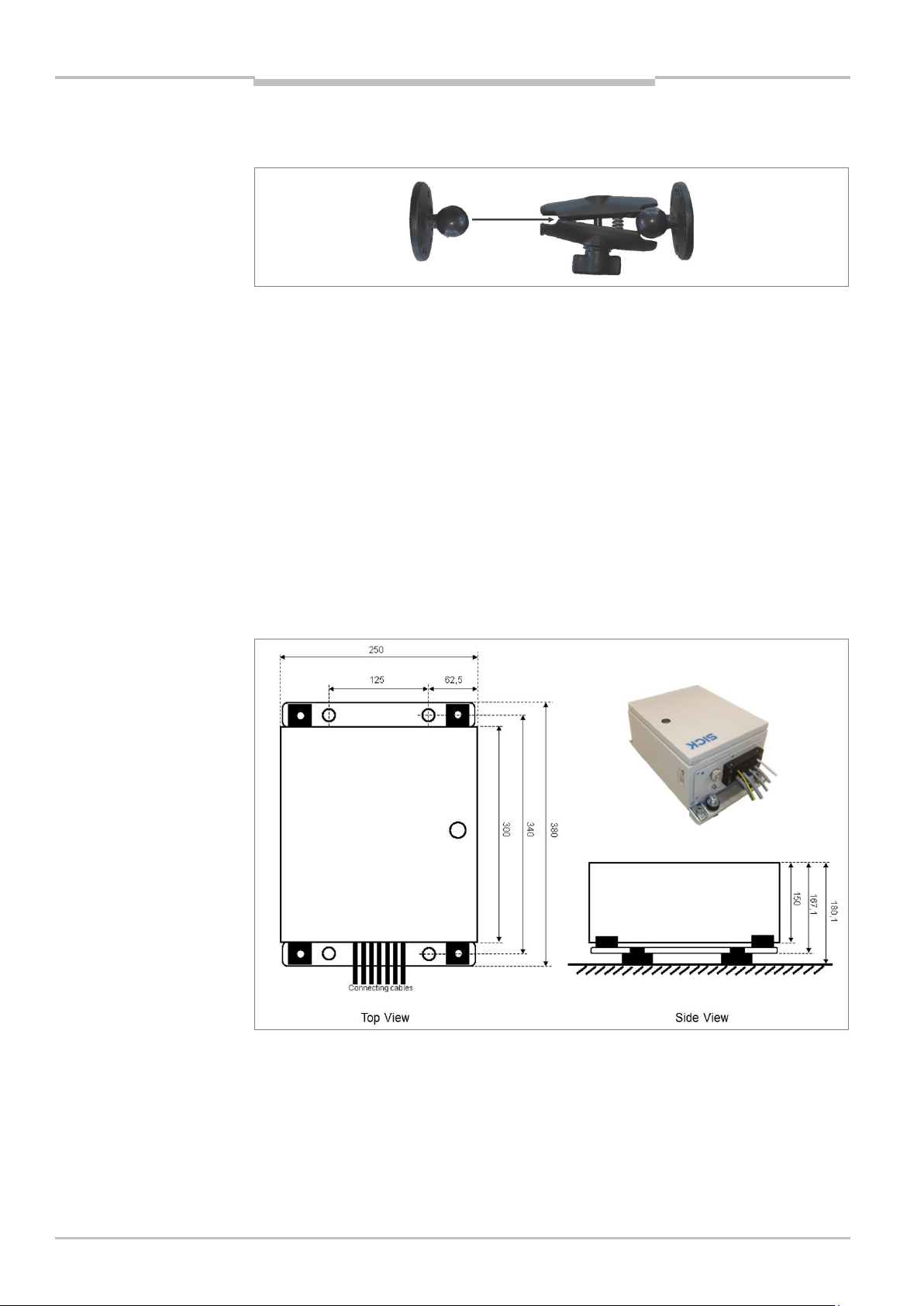
10.2.4 Control cabinet dimensional drawing ..............................................80
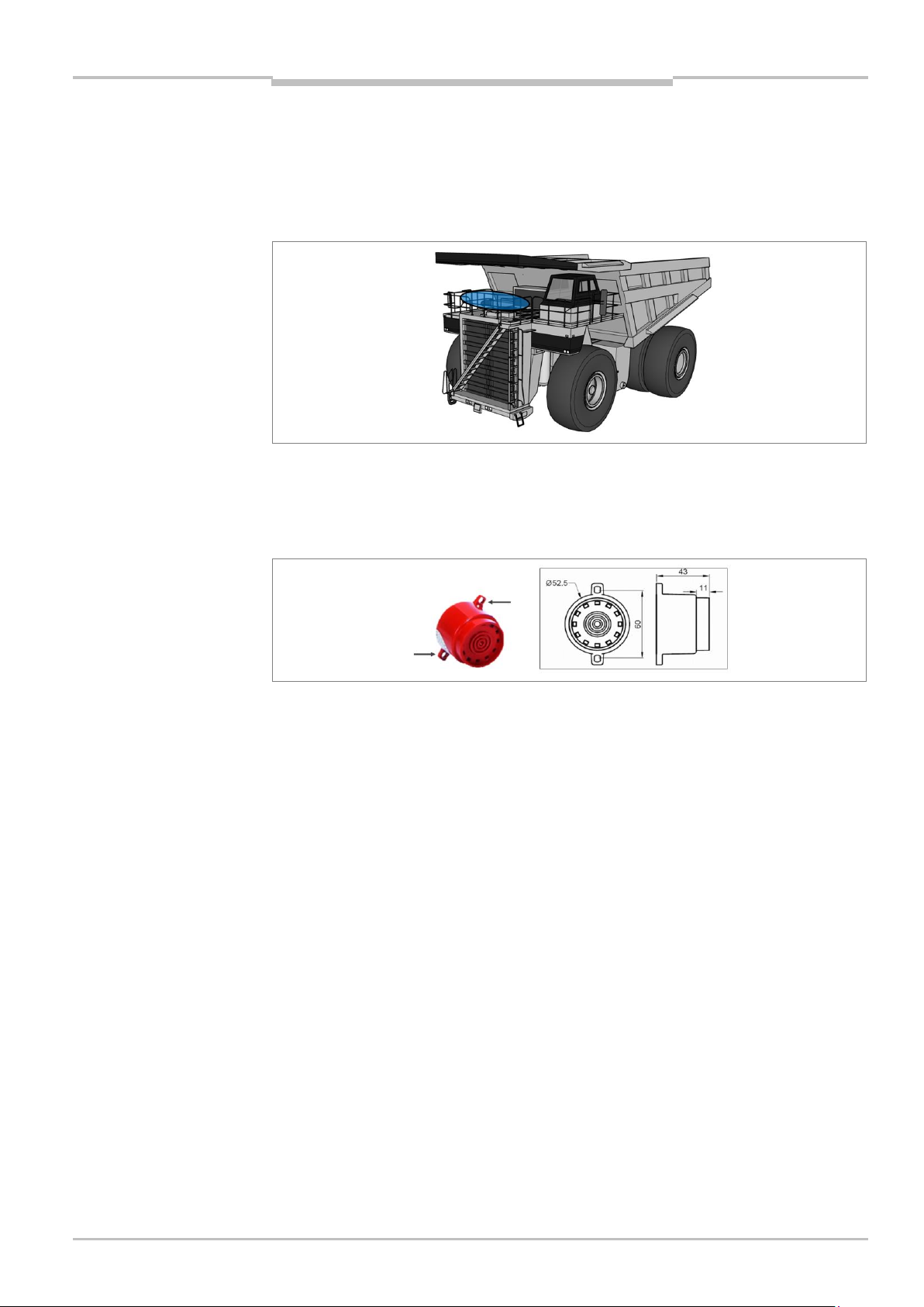
10.2.5 Tone buzzer dimensional drawing....................................................80
10.3 Tone selection for tone buzzer ...........................................................................81
11 Figures and tables ...........................................................................................................82
11.1 List of tables ........................................................................................................82
11.2 List of figures .......................................................................................................83
11.3 Keywords index ...................................................................................................85
8021799/2017-09-26 Operating Instructions | SICK 5
Subject to change without notice
Page 6

Chapter 1 Operating Instructions
About these operating instructions
Activities
Target group
Mounting, electrical installation,
maintenance, and replacement
of system components
Qualified personnel, such as service technicians
or industrial electricians
Commissioning and
configuration
Qualified personnel, such as technicians or
engineers
Operating the system
Personnel qualified in running and operating the
system (truck operators)
Note
TPS
1 About these operating instructions
Please read through this chapter carefully before you use the documentation and work
with the TPS driver assistance system.
1.1 Function of this document
These operating instructions are designed to give technical personnel instructions on
the safe mounting, configuration, electrical installation, commissioning, operation and
maintenance of the Truck Protection System TPS.
These operating instructions do not provide information on operating the vehicle into
which the TPS is or will be integrated. For information about this instruction, refer to the
vehicle's operating instructions.
1.2 Target group
These operating instructions are intended for people who install, connect, commission,
operate, and maintain TPS.
Tab. 1 Target group
1.3 Information depth
These operating instructions contain information about the TPS driver assistance system
on the following topics:
Product description
Mounting
Electrical installation
Commissioning and configuration
Operation
Maintenance and repairs
Fault diagnosis and troubleshooting
Technical data and dimensioned drawings
When planning and using the TPS driver assistance system, technical skills are required
that are not covered by this document.
The official and legal regulations for operating the TPS must always be complied with.
Further information about the device components used in the TPS can be found in the
accompanying operating instructions.
6 Operating Instructions | SICK 8021799/2017-09-26
Subject to change without notice
Page 7

Operating Instructions Chapter 1
About these operating instructions
TPS
LD-MRS
LMS
RDW
Recommendation
Note
1. / 2. ...
,
,
TPS
1.4 Abbreviations used
Truck Protection System = driver assistance system for haul trucks
Ladar Digital (Laser Radar) Multi-Layer Range Scanner = 3D LiDAR sensor from SICK AG
Laser measurement sensor = 2D LiDAR sensor from SICK AG
Road Departure Warning = functionality against unintended road departure
1.5 Symbols used
Recommendations are designed to assist you in the decision-making process with respect
to the use of a certain function or technical measure.
Notes provide information about the features of a device, application tips, or other
information that may come in useful.
Instructions that must be carried out in the described order are referred to as step-by-step
instructions and are indicated by numbered lists. Carefully read and follow the instructions
for action.
Instructions for taking action are indicated by an arrow. Carefully read and follow the
instructions for action.
LED symbols describe the status of a diagnostics LED. Examples:
The LED is illuminated continuously.
The LED is flashing.
The LED is off.
Display symbols show the status of the 7-segment display:
Constant display of characters, e.g., U
Flashing display of characters, e.g., 8
Alternating display of characters, e.g., L and 2
8021799/2017-09-26 Operating Instructions | SICK 7
Subject to change without notice
Page 8

Chapter 2 Operating Instructions
Safety
NOTE
Note
TPS
2 Safety
This chapter concerns your own safety and the safety of the system operator.
Please read this chapter carefully before you begin working with TPS.
2.1 Qualified safety personnel
The TPS must only be mounted, commissioned, and maintained by adequately qualified
personnel.
A qualified person
has sufficient skills in the field of the respective equipment based on their technical
training and experience and
has been instructed by the manufacturer in system operation and all applicable safety
guidelines and
is familiar with all relevant country-specific occupational safety regulations, work safety
regulations, guidelines, and generally accepted technical rules and standards (e.g.,
DIN standards, VDE regulations, country-specific rules) to such an extent that he/she
is able to evaluate the safe condition of the power-operated equipment and if he/she
has access to and has read the operating instructions.
2.2 Applications of the system
TPS is a driver assistance system for haul trucks in surface mining. It consists of three
LiDAR sensors, a control cabinet, GPS and an interactive operator display.
The system warns the operator of possible collisions, entering hazardous areas (black
spots) and departure of the road (RDW).
During the operation of the truck, the TPS will constantly monitor the surrounding of the
vehicle for obstacles. If an obstacle is detected in one or more of the configured warning
zones, the zone violation is reported to the operator visually and audibly.
When the truck enters a pre-defined black spot like a hazardous intersection, the crusher
or workshop area, the system indicates this by a visual and audible alarm as well.
In case the truck comes to close or too far away from the bund wall the road departure
warning function alerts the operator with an visually and acoustically alarm.
TPS only detects objects which are visible in the measurement plane for the LiDAR
sensor. Therefore, the LiDAR sensor must have a free view of the area to be monitored.
Using TPS means that hazardous situations, such as vehicles, equipment, infrastructure,
unintentional road departure, hazard areas or dangerous queuing up situations are
detected in good time and that accidents during operating are avoided.
8 Operating Instructions | SICK 8021799/2017-09-26
Subject to change without notice
TPS is a driver assistance system. This means that at all times the driver bears the full
responsibility for safe operation, in particular for people who are in the hazardous zones of
the vehicle.
Page 9
Operating Instructions Chapter 2
Safety
NOTE
HAZARD
WARNING
CAUTION
NOTE
TPS
2.3 Intended use
TPS may only be used as described in section 2.2 Applications of the system. It may only
be used by qualified personnel in the environment in which it was mounted and initially
commissioned by qualified safety personnel in accordance with these operating
instructions.
TPS is not a safety device for human protection and it therefore does not comply with
any safety standards. For safety applications, please contact SICK AG.
In the event of any other usage or of modification to the system – including in the context
of mounting and installation – any claims against SICK AG under the warranty will be
rendered void.
2.4 General safety notes and protective measures
2.4.1 Safety notes and symbols
The following safety and hazard symbols are used for your own safety, for the safety of
third parties, and for the safety of the machine. You must therefore observe these symbols
at all times.
Denotes an immediate hazard that may result in severe to fatal injuries.
The symbol shown on the left-hand side of the note refers to the type of hazard in question
(the example here shows a risk of injury resulting from electrical current).
Denotes a potentially dangerous situation that may result in severe to fatal injuries.
The symbol shown on the left-hand side of the note refers to the type of hazard in question
(the example here shows a risk of damage to the eye by laser beams).
Denotes a potentially dangerous situation that may result in minor personal injury or
possible material damage.
Denotes a potential risk of damage or functional impairment to the device or the devices
connected to it.
This symbol includes a reference to supplementary technical documentation.
8021799/2017-09-26 Operating Instructions | SICK 9
Subject to change without notice
Page 10

Chapter 2 Operating Instructions
Safety
WARNING
WARNING
TPS
2.4.2 General safety notes
TPS has been designed in a way that allows for safe operation. However, a certain level of
risk will always remain.
Awareness of potential sources of danger in the system will help you to work in a safer
manner and thus prevent accidents.
To avoid risks, please also observe the special warnings in each of the individual chapters.
Safety notes
Observe the following to ensure the safe use of the system as intended.
The notes in these operating instructions must be complied with.
All official and statutory regulations governing the operation of the system must be
complied with.
The national and international legal specifications apply to the installation and use of
the system, to its commissioning, and to recurring technical inspections, in particular:
– The accident prevention regulations and work safety regulations
– Any other relevant safety regulations
The checks must be carried out by qualified safety personnel or specially qualified and
authorized personnel, and must be recorded and documented to ensure that the tests
can be reconstructed and retraced at any time.
These operating instructions must be made available to the operator of the system.
The system operator must be instructed by qualified safety personnel and must read
the operating instructions.
The driver must follow relevant instructions and conduct inspections in order to ensure
that the screens of all LiDAR sensors are clean and undamaged
The LiDAR sensors must have a free field of vision. The sensor head must not be
covered by other objects, for example.
SICK AG recommends carrying out a system check before commissioning the system.
10 Operating Instructions | SICK 8021799/2017-09-26
Subject to change without notice
Risk resulting from improper operation
Improper installation and commissioning, damaged components, and unsuitable ambient
conditions such as excessively cold or warm temperatures and high levels of dust, fog or
spray, may cause faults and faulty alarms and may result in a complete system crash.
Page 11
Operating Instructions Chapter 2
Safety
WARNING
WARNING
WARNING
CAUTION
Important
TPS
System does not comply with safety standards
TPS is not suitable for the protection of humans within the meaning of the applicable
safety standards for machines. The system therefore does not comply with safety
standards.
TPS is a driver assistance system. It provides the driver with visual and acoustic warnings
about objects outside of the truck, hazardous areas and departure of the road. At all times
the driver bears the full responsibility for safe operation, in particular for people who are in
the hazardous zones of the truck.
Location of use
The system is intended exclusively for use in industrial environments.
2.4.3 Potential sources of danger
Laser protection
Damage to the eye by laser beams
The LD-MRS 3D LiDAR senor used by TPS conform to laser class 1 (eye-safe) as per
EN/IEC 60825-1 (see laser warning label on the device for publication date), 21 CFR
1040.10 and 21 CFR 1040.11.
The LMS151 2D LiDAR sensor used by TPS corresponds to laser class 1 (eye safe) as per
EN/IEC 60825-1 (see laser warning label on the device for publication date).
This complies with 21 CFR 1040.10 with the exception of the deviations as per Laser
Notice No. 50, June, 2007.
The laser operates at a wavelength γ = approx. 905 nm (invisible infrared light). The laser
beam is not visible to the human eye.
The radiation emitted in normal operation is harmless to human skin and eyes.
Improper use (e.g., opening the housing and stopping the motor) can result in dangerous
exposure to radiation.
Never open the LiDAR sensor housing. Opening the housing does not interrupt the
operation of the laser beam.
Observe the laser safety regulations as per IEC 60 825-1 (latest version).
No maintenance is required to ensure compliance with laser class 1.
The laser output apertures are the optics cover on the LMS151 and LD-MRS LiDAR
sensors.
The laser warning is located on the right side of the LiDAR sensor.
8021799/2017-09-26 Operating Instructions | SICK 11
Subject to change without notice
Page 12
Chapter 2 Operating Instructions
Safety
HAZARD
WARNING
NOTE
WARNING
TPS
Electrical current
Risk of injury and damage caused by electrical current
Improper handling of live devices may lead to severe personal injury or death by electric
shock.
Electrical installation and maintenance work must always be carried out by personnel
authorized to do so.
The voltage supply must be disconnected when attaching and detaching electrical
connections.
Select and implement wire cross-sections and their correct fuse protection in
accordance with the applicable standards.
Do not touch any live components.
In the event of danger, immediately disconnect the system from the voltage supply.
Always use original fuses with the specified current rating.
Report any damaged cables to the maintenance team without delay.
Observe the current safety regulations when working on electrical systems.
Commissioning/Operation/Maintenance
Risk resulting from incorrect commissioning and configuration
Do not commission without testing by qualified safety personnel!
Before you operate the system or a device for the first time, you must have it checked and
approved by qualified safety personnel.
Claims under the warranty rendered void
Do not open the device housing. The devices are sealed.
If the device is opened, any warranty claims against SICK AG will be void.
Risk resulting from faults
Cease operation if the cause of the malfunction has not been clearly identified.
A defect in the system may result in fatal accidents or damage to the system.
Take the TPS out of operation if you cannot clearly identify the fault and if you cannot
safely remedy the problem.
12 Operating Instructions | SICK 8021799/2017-09-26
Subject to change without notice
Page 13

Operating Instructions Chapter 2
Safety
Note
TPS
2.5 Protection of the environment
The system has been designed to minimize its impact on the environment. It consumes
very little power.
Always act in an environmentally responsible manner at work. For this reason, please note
the following information regarding disposal.
2.5.1 Power consumption
Including its components, the system typically consumes 40 W.
The peak power consumption when starting up or in the event of integrated sensor heating
is 150 W.
2.5.2 Disposal after final decommissioning
Always dispose of unusable or irreparable devices in an environmentally safe manner in
accordance with the relevant national waste disposal regulations.
Dispose of all electronic assemblies as hazardous waste. The electronic assemblies are
easy to dismantle.
SICK AG does not take back devices that are unusable or irreparable.
8021799/2017-09-26 Operating Instructions | SICK 13
Subject to change without notice
Page 14
Chapter 3 Operating Instructions
Product description
Note
Important note
TPS
3 Product description
This chapter provides information on the special properties of the TPS driver assistance
system. It describes the design and operating principle of the system.
Always read this chapter before you mount, install and commission the system.
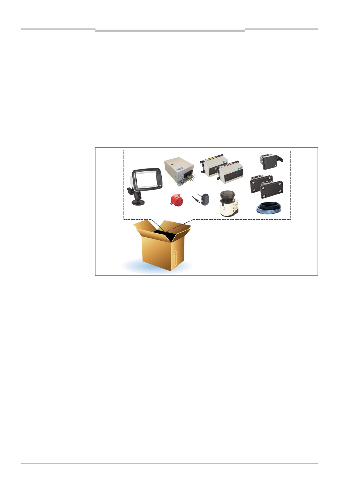
3.1 Scope of delivery
TPS consists of an LMS151 2D LiDAR sensor and two LD-MRS 3D LiDAR sensors, an
interactive operator display, a control cabinet, mounting kits with shock mounts and
connecting cables, GPS receiver, as well as a tone buzzer. Light signals can be optionally
used.
Fig. 1: Scope of delivery for TPS
Thorough check for completeness
It is recommended that you carefully check for and report transport damage of any kind
as soon as possible after receiving the system.
Also verify that the delivery includes all components listed on the delivery note.
3.2 System components
3D LiDAR sensor LD-MRS HD Front and Rear
The 3D LiDAR sensor LD-MRS HD mounted on the front and rear of the truck constantly
monitors the area in front resp. behind the truck, in a radius of up to 200 m (max. value of
warning zone of front LiDAR sensor).
The object detection is done with laser beams that the LD-MRS emits in four stacked
planes. The device measures the distance and the direction (the angle to the LD-MRS) of
the object.
14 Operating Instructions | SICK 8021799/2017-09-26
Subject to change without notice
Page 15
Operating Instructions Chapter 3
Product description
TPS
The aperture angle is 100° for the front and back sensor.
Fig. 2: Laser output aperture of the LD-MRS Front and Rear
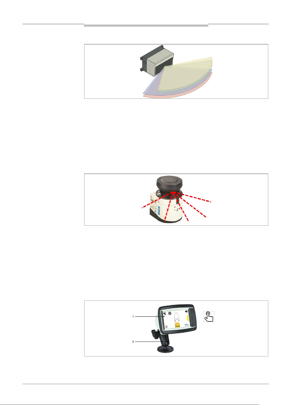
2D LiDAR sensor LMS151 RDW
The 2D LiDAR sensor LMS151 RDW mounted on the front of the truck constantly monitors
the area to the side of the truck.
The 2D LiDAR sensor scans its surroundings using a laser beam in a plane in the time-of-
flight process. The maximum aperture angle is 180°. If the emitted laser beam is reflected
by an object, the distance to the object is calculated.
Failure to install a suitable shock and vibration damper may result in a reduced system life
cycle.
Fig. 3: Laser output aperture of the LMS151 RDW
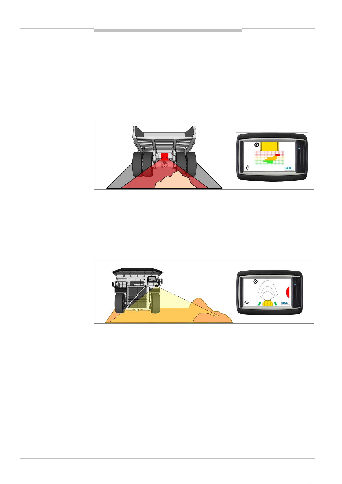
The operator display
The interactive operator display is the central component of the system. It visualizes the
outline of the truck and the warnings to the driver. Obstacles in the monitored area are
identified, and therefore can be quickly localized.
The display has a touch screen (1), which allows the operator to make entries during initial
commissioning and subsequent operation.
The operator display is attached to a mounting kit (2) with a swivel connector in the truck,
within the operators's field of view.
Fig. 4: Operator display with mounting kit
8021799/2017-09-26 Operating Instructions | SICK 15
Subject to change without notice
Page 16
Chapter 3 Operating Instructions
Product description
TPS
Control cabinet
The control cabinet connects the LiDAR sensors with the operator display. It also process
input signals and provides various output signals and power to the components.
Fig. 5: Control cabinet
To protect the control cabinet from shocks and vibration, damping measures must be
installed. The control cabinet comes with shock absorber mounting brackets.
Tone buzzer
A tone buzzer supports the visual warning about an obstacle on the display with an
acoustic warning.
Fig. 6: Tone buzzer
GPS receiver
A GPS receiver is used for ego localization in world coordinates, speed, heading and more
information.
Fig. 7: GPS receiver
16 Operating Instructions | SICK 8021799/2017-09-26
Subject to change without notice
Page 17

Operating Instructions Chapter 3
Product description
Note
TPS
Mounting kits with shock mounts
The TPS comes with mounting brackets with build-in shock absorber for the LMS151 RDW
and for both LD-MRS Rear and Front LiDAR sensors.
To protect the system components (sensors, control cabinet, operator display) from shocks
and vibration, damping measures must be installed. SICK AG recommends using the
included mounting kits with shock mounts that has built-in damper elements.
Failure to install a suitable shock and vibration damper may result in a reduced system life
cycle.
Fig. 8: Mounting kit for LMS151 RDW and LD-MRS Front and Rear
3.3 System functionality
The TPS is a driver assistance system for proximity detection and collision awareness for
heavy mining trucks. The system warns the operator of possible collisions, entering
hazardous areas (black spots) and departure of the road (RDW).
During the operation of the truck, the TPS will constantly monitor the surrounding of the
vehicle for obstacles. If such an obstacle is detected in one or more of the configured
warning zones, the zone violation is reported to the operator visually and audibly.
When the truck enters a predefined black spot like a hazardous intersection, the crusher
or workshop area, the system indicates this by a visual and audible alarm as well.
In case the truck comes to close or too far away from the left bund wall the road departure
warning function alerts the operator with an visually and acoustically alarm as well.
3.3.1 Front collision warning
The LD-MRS HD Front 3D LiDAR sensor monitors the area in front of the truck. It raises an
alarm when an obstacle is violating one of the 3 warning zones (green, yellow, red).
The range of the frontal warning zones is adapted automatically to the current driving
speed of the truck. Speed information is generated by the GPS receiver. In case GPS is
currently not available TPS uses as fall back the so called “low speed warning zones”.
8021799/2017-09-26 Operating Instructions | SICK 17
Subject to change without notice
Fig. 9: Front collision warning
Page 18
Chapter 3 Operating Instructions
Product description
Note
TPS
3.3.2 Rear End collision warning
The rear end collision warning supports the operator while he is driving in reverse gear
with low speed like when parking, unloading and reversing to a shovel.
The area directly behind the truck is monitored by the rear sensor. The LD-MRS HD Rear
3D LiDAR sensor scans the area behind the wheels and watches for obstacles like walls,
light or heavy vehicles or other mine site equipment that violate the light curtain by their
height.
The rear surveillance is activated only while the truck is in reverse gear. The wheels are
detected by the system and the measured points of the wheels are hidden.
Fig. 10: Rear End collision warning
3.3.3 Road Departure Warning
The Road Departure Warning (RDW) function monitors the distance between the truck and
the left roadside barrier, i.e. bund walls. If the truck violates the set safety distances to
either side, a warning is issued to the driver. Broken bund wall or big rocks at the mine site
are be filtered automatically by the system for a smooth operation. The road boarder is
detected by the 2D LiDAR sensor LMS151 RDW.
Fig. 11: Road Departure Warning Function with In-Lane Symbol
The 2D LiDAR sensor must identify the bund wall to activate this function. Two green
blocks to the left and right of the truck on the display are indicating that the truck is in
lane.
RDW Pause Signal
The system provides a pause signal input. The signal is muting the alarm unit for the
following 30 seconds.
18 Operating Instructions | SICK 8021799/2017-09-26
Subject to change without notice
Page 19
Operating Instructions Chapter 3
Product description
Note
TPS
RDW Flash Lights (Optional)
Two relay outputs are provided on two 2-wire cables for connection to external RDW signal
lights on the left and right front of the truck.
If the truck is in lane, both RDW lights are illuminated continuously
If the truck is moving unintentionally too close to the left bund wall, only the right light is
illuminated. The left RDW light will not be illuminated anymore.
In case of unintentional read departure to the right (center of the lane), only the left
RDW light is illuminated. The right RDW light is not illuminated anymore. This informs
truck drivers in the opposite direction that the truck is leaving the lane.
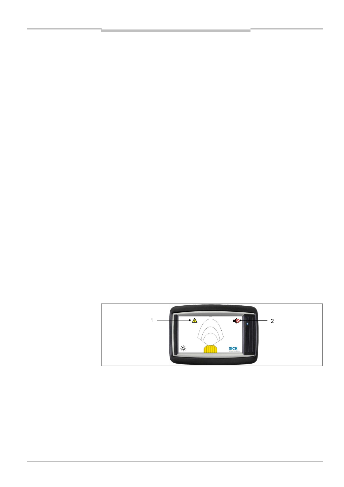
3.3.4 Black Spot Warning
TPS provides a function to mark mine site areas with GPS positions. Each GPS position
defines a position in world coordinates with a circular area around it. This area is called
“black spot” (1). This function can be used for two purposes:
On mine site may be locations where the road departure warning system has no usable
roadside barrier as a side reference. These locations may be crossroads,
loading/unloading or construction areas. These areas may be marked by their positions,
disabling the RDW function in their vicinity and thus suppressing false warnings.
Also the position is used for “black spot” marking and identification. Black spots are
hazardous areas like intersections, construction areas, crushers and workshops. TPS
warns the operator when the truck is entering a black spot to raise operator’s attention.
If the black spot is activated for the area the truck is currently placed or driving, the GPS
position is stored and a black spot with the radius of 80m (by default) is created and
stored.
Inside black spot areas, the driver may also disable all acoustic warnings (2). Therefore,
the speaker-icon is shown while the truck is inside the black spot area. Pressing this icon
disables all sound output.
The sound output is automatically turned on again when leaving the black spot area. This
function may be used to mute TPS while the truck is in maintenance in a workshop.
Note that for the correct function of black spots, GPS must be available.
8021799/2017-09-26 Operating Instructions | SICK 19
Subject to change without notice
Fig. 12: Black Spot Warning
Page 20

Chapter 3 Operating Instructions
Product description
Display
Meaning
LMS151 measuring and no error reported
LMS151 is either not in measuring mode (stopped by the user) or it is
running in measuring mode, but errors have occurred
OFF: no contamination (optics cover)
ON: contamination warning
Blinking: contamination error
Not used
Not used
TPS
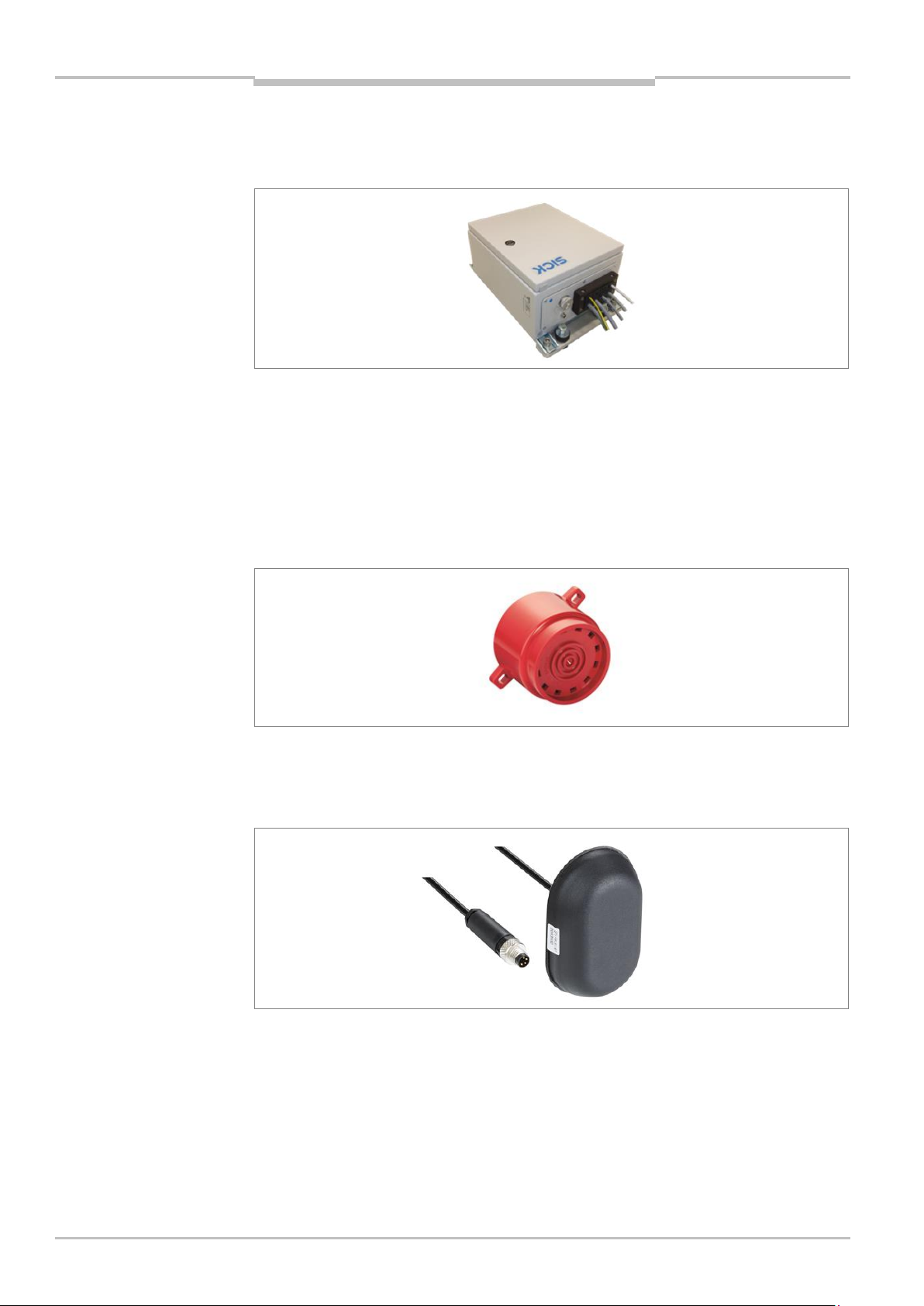
3.4 Status indicators
2D LiDAR sensor
The 2D LiDAR sensor is fully automated in normal operation — no operator intervention is
required. The LEDs (1) signal the operational status of the 2D LiDAR sensor. In addition,
the 7-segment display (2) is also available for diagnostics when errors or faults occur
(see chapter 9.2 Fault indicators of the LMS151).
Fig. 13: Status indicators for the LMS511
Tab. 2: Status indicators of the LMS151
20 Operating Instructions | SICK 8021799/2017-09-26
Subject to change without notice
Page 21
Operating Instructions Chapter 3
Product description
TPS
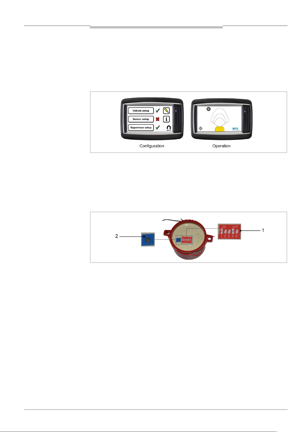
Operator display
The operator display distinguishes between two operating modes. The system enters
configuration mode when it is first started or following unlocking via the web interface.
It contains assistants for the configuration of the LiDAR sensor, the vehicle dimensions
and the supervisor setup.
In the operating mode, the display assists the operator with collision awareness, driver
assistance and for setting black spot warnings.
Fig. 14: The operator display in configuration and operating mode
Tone buzzer
The tone buzzer does not have any status indicators.
The DIP switch on the underneath of the housing can be used to set the tone selection (1)
and the volume (2).
Recommended settings: OFF, ON, ON, OFF, ON (01101)
Fig. 15: DIP switch on the tone buzzer
Additional information on this can be found in the appendix in chapter 10.3 Tone
selection for tone buzzer.
8021799/2017-09-26 Operating Instructions | SICK 21
Subject to change without notice
Page 22

Chapter 4 Operating Instructions
Mounting
NOTE
WARNING
Important note
Note
TPS
4 Mounting
4.1 Function test before mounting
Before mounting the TPS components on the truck, it is recommended that the functional
readiness of the devices should be checked.
1. Place the components on a table.
2. Connect the components according to the wiring diagram (see chapter 5.1 Wiring plan).
3. Establish the supply voltage and check the general operational readiness of the
components (see chapter 6.1 Launching the system).
It is recommended that the length of the cable should be checked in advance.
The control cabinet is equipped with fuses both in the 24 V and ground voltage supply
lines. If any of these fuses blow, disconnect from power immediately and check for the
cause.
4.2 Mounting the LiDAR sensor
The reliable and problem-free operation of the system depends primarily on the proper
mounting and alignment of the LiDAR sensor.
Be sure to closely observe the following notes during mounting:
Mount the LiDAR sensor so that it is protected from dirt and damage.
Ensure that the field of vision of the entire optics cover is not restricted.
Always mount the LiDAR sensors such that you are able to insert and remove the
connectors.
Avoid excessive shock and vibration loading on the LiDAR sensor.
In the event of heavy vibration, prevent the fixing screws from accidentally coming loose
using screw-locking devices.
The fine alignment is carried out later during the commissioning with the support of a
setup assistant (see chapter 6.4 Configuring the LiDAR sensors).
Make sure that the screws are easily accessible for fine alignment.
22 Operating Instructions | SICK 8021799/2017-09-26
Subject to change without notice
Page 23
Operating Instructions Chapter 4
Mounting
TPS
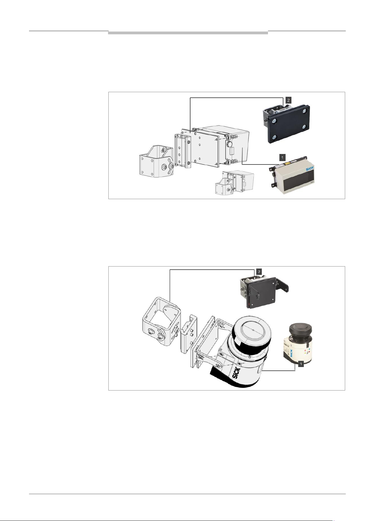
Mounting LD-MRS HD Front and Rear
Mounting is carried out using the supplied mounting kit with shock absorber (2) for the LDMRS. For mounting the LD-MRS (1) safely at the mounting location, 4 M6 screws with
washers and lock washers are required. The supply voltage of the LD-MRS must be
switched off.
Fig. 16: Mounting the LD-MRS using mounting kit with shock absorber
Mounting LMS151 RDW
Mounting is carried out using the supplied mounting kit with shock absorber (2) for the
LMS151 RDW. For mounting the LMS151 RDW (1) safely at the mounting location, 4 M5
screws with washers and lock washers are required. The supply voltage of the LMS151
RDW must be switched off.
8021799/2017-09-26 Operating Instructions | SICK 23
Subject to change without notice
Fig. 17: Mounting the LMS151 RDW using mounting kit with shock absorber
Page 24
Chapter 4 Operating Instructions
Mounting
Note
Note
TPS
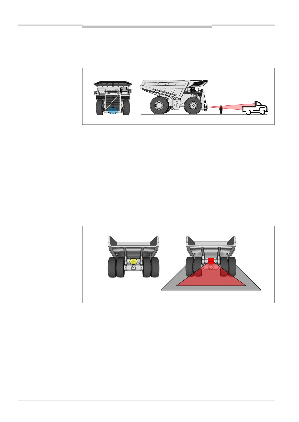
Mounting LD-MRS HD Front to the vehicle
The frontal sensor must be mounted at the very front of the truck, with its area of view
unobstructed in driving direction. The mounting height must be chosen so that relevant
objects, such as pick-up trucks, are within the area of view.
Fig. 18: Mounting position of the LD-MRS HD Front
For the best 3D LiDAR sensor coverage also of the very near proximity in front, the
mounting position marked in blue should be considered.
Please avoid obstructions due to the ladder etc. Recommended mounting height is approx.
1.7 m. Additional protective measures for the scanner would be required for this mounting
height (e.g. mud coverage etc.)
Mounting LD-MRS HD Rear to the vehicle
The rear collision protection system monitors the area directly behind the truck for
obstacles. The 3D LiDAR sensor is typically mounted above the rear axle of the truck
pointing downwards at an angle of about 45 degrees.
The scanner should be mounted close to the rear center of the truck.
24 Operating Instructions | SICK 8021799/2017-09-26
Subject to change without notice
Fig. 19: Mounting position of the LD-MRS HD Rear
The exact angle is defined by its mounting height and will be adjusted during system
setup. Please avoid unnecessary obstructions.
Page 25
Operating Instructions Chapter 4
Mounting
Note
TPS
Mounting LMS151 RDW to the vehicle
The Road Departure Warning (RDW) LiDAR sensor must be mounted at the front of the
truck, towards the left side. The sensor is mounted with a tilt angle of approximately 35
degrees downwards as its field of view must include the road surface in front of the truck
as well as the left-side road barrier/ wall.
Fig. 20: Mounting position of the LMS151 RDW
The exact angle is defined by its mounting height and will be adjusted during system
setup. Please avoid unnecessary obstructions.
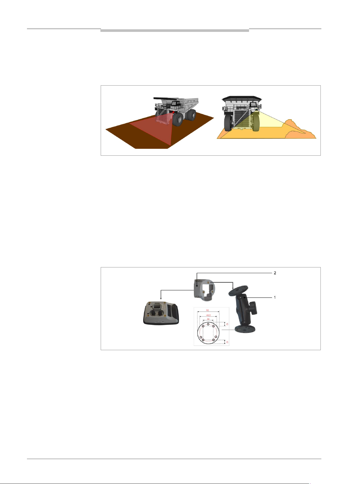
4.3 Mounting the bracket for the operator display
The operator display is mounted in the truck cab. It must be clearly visible for the truck
driver without them having to turn their head.
The operator display is mounted using the mounting kit included with delivery. This means
that the display is additionally protected against mechanical shocks.
The mounting kit is made up of the bracket (1) and an adapter (2) to hold the operator
display.
Fig. 21: Mounting the operator display
8021799/2017-09-26 Operating Instructions | SICK 25
Subject to change without notice
Page 26
Chapter 4 Operating Instructions
Mounting
Note
Note
TPS
Assemble the bracket and mount in the driver's cab
1. Assemble the individual components of the bracket as shown in the figure.
2. Mount the bracket in the vehicle. In order to do this, screw the foot of the bracket tight
in a suitable location in the truck cab.
The adapter and operator display are mounted during the electrical installation.
The connecting cables have to be inserted into the operator display in a later step. (see
chapter 5.4 Connecting the operator display).
4.4 Mount the control cabinet
The control cabinet must be mounted in a dry and cool position in the inside of the truck
e.g. inside the cabin behind the operator or passenger seat. It is not intended for outside
mounting.
Before mounting the control cabinet, check that all components can be reached by the
supplied cables.
26 Operating Instructions | SICK 8021799/2017-09-26
Subject to change without notice
Fig. 22: Mounting the control cabinet
Page 27
Operating Instructions Chapter 4
Mounting
TPS
4.5 Mount the GPS receiver
The GPS receiver - with integrated antenna - must be mounted on the outside of the truck.
It must be in possible best clear view of the sky, but protected from mechanical
destruction like falling rocks. The recommended place is along the front railing of the
truck.
Fig. 23: Mounting the GPS receiver
4.6 Mounting the tone buzzer
Mount the tone buzzer in the operator cab behind the driver.
Fig. 24: Mounting the tone buzzer
8021799/2017-09-26 Operating Instructions | SICK 27
Subject to change without notice
Page 28

Chapter 5 Operating Instructions
Electrical installation
HAZARD
HAZARD
TPS
5 Electrical installation
Disconnect the power to the system
Make sure that all TPS components are disconnected from the voltage supply
during electrical installation.
Risk of injury due to electrical current
Standard safety requirements must be met when working on electrical systems.
The voltage supply must be disconnected when attaching and detaching electrical
connections.
5.1 Wiring plan
Establish the connections in accordance with the following wiring plan. Connect the
components according the wiring connection overview inside the control cabinet.
28 Operating Instructions | SICK 8021799/2017-09-26
Subject to change without notice
Fig. 25: TPS wiring plan
Page 29

Operating Instructions Chapter 5
Electrical installation
TPS
8021799/2017-09-26 Operating Instructions | SICK 29
Subject to change without notice
Fig. 26: TPS wiring connection overview (inside control cabinet)
Page 30

Chapter 5 Operating Instructions
Electrical installation
No.
Connection
Description
1
Ethernet
Ethernet connection to a control cabinet
2
Data interfaces/synchronization
Not assigned
3
Power
Connection to the control cabinet
TPS
5.2 Connecting the LD-MRS front and rear LiDAR sensor
The 3D LiDAR sensor LD-MRS Front and LD-MRS Rear mounted on the front resp. on the
rear are connected to the control cabinet for power and the Ethernet connection.
The LD-MRS Front and Rear have the following connections:
Fig. 27: LD-MRS connections
Tab. 3: LD-MRS connections
Connection to voltage supply
The cable to connect the LD-MRS Front and Rear to the voltage supply has a round plug-in
connector on one side. The other side has an open end.
30 Operating Instructions | SICK 8021799/2017-09-26
Subject to change without notice
Fig. 28: Connecting the LD-MRS to the control cabinet
1. Connect the round plug-in connector the connecting cable on the LD-MRS to the Power
female connector.
2. Run the connecting cable from the 3D LiDAR sensor to the control cabinet.
3. Connect the LD-MRS to the terminal block inside the control cabinet.
Page 31

Operating Instructions Chapter 5
Electrical installation
Wire color
Connection Terminal Block
Voltage supply
LD-MRS Front
LD-MRS Rear
Yellow
13
14
+24 V (Voltage)
Gray
13
14
+24 V (Voltage)
White
3 4 0 V (Ground)
Blue
3 4 0 V (Ground)
No.
Connection
Description
1
Power
Connection to the voltage supply
2
Data
Not assigned
3
I/O
Not assigned
4
Ethernet
Connection to the network
TPS
Place the wires in the control cabinet as follows.
Tab. 4: Connecting the LD-MRS Front and Rear to the voltage supply
Connection to Ethernet switch
Connect the 3D LiDAR sensor Front and Rear with the Ethernet switch inside the control
cabinet. Use the connecting cable with the round plug-in and the RJ45 connector.
Fig. 29: Connecting the LMS511 to the Ethernet switch
1. Connect the round plug-in connector into the female Ethernet connector of the 3D
LiDAR sensor.
2. Run the Ethernet cable from the 3D LiDAR sensor to the control cabinet.
3. Connect the RJ45 connector into a free port on the Ethernet switch.
5.3 Connecting the LMS151 RDW LiDAR sensor
The 2D LiDAR sensor LMS151 RDW mounted on the front for road departure warning is
connected to the control cabinet for power and the Ethernet connection.
The LMS151 RDW has the following connections:
Fig. 30: LMS151 connections
Tab. 5: LMS151 connections
8021799/2017-09-26 Operating Instructions | SICK 31
Subject to change without notice
Page 32

Chapter 5 Operating Instructions
Electrical installation
Wire color
Connection Terminal Block
Voltage supply
Brown
15
+24 V (Voltage)
White
15
+24 V (Voltage)
Blue
5
0 V (Ground)
Black
5
0 V (Ground)
Note
TPS
Connection to voltage supply
The cable to connect the LMS151 RDW to the voltage supply has an M12 plug connector
on one side. The other side has an open end with a shield.
Fig. 31: Connecting the LD-MRS to the control cabinet
1. Screw the M12 round connector of the connecting cable on the LMS151 to the Power
female connector.
2. Run the connecting cable from the 2D LiDAR sensor to the control cabinet.
It is recommended that cable shielding should be used for bundled and safe installation
of the cables.
3. Connect the LD-MRS to the terminal block inside the control cabinet.
Place the wires in the control cabinet as follows.
Tab. 6: Connecting the LMS151 RDW to the voltage supply
Connection to Ethernet switch
Connect the 2D LiDAR sensor RDW with the Ethernet switch inside the control cabinet. Use
the connecting cable with the M12 plug connector and the RJ45 connector.
Fig. 32: Connecting the LMS511 to the Ethernet switch
1. Screw the M12 round connector into the female Ethernet connector of the 2D LiDAR
sensor.
2. Run the Ethernet cable from the 2D LiDAR sensor to the control cabinet.
3. Connect the RJ45 connector into a free port on the Ethernet switch.
32 Operating Instructions | SICK 8021799/2017-09-26
Subject to change without notice
Page 33

Operating Instructions Chapter 5
Electrical installation
Pin
Wire no.
Description
POWER
1 1 24 V
2 2 24 V
3 3 GND
4 4 GND
Pin assignment
TPS
5.4 Connecting the operator display
The operator display mounted in the operator's cab is connected to the voltage supply and
the Ethernet switch inside the control cabinet.
Fig. 33: Connecting the operator display
Tab. 7: Operator display – pin allocation of the connecting cable
Ethernet connecting cable
The Ethernet cable for connecting the display and control cabinet has an angled M12 male
connector (for connection on the display side) and a RJ45 connector (for connection on the
control cabinet).
8021799/2017-09-26 Operating Instructions | SICK 33
Subject to change without notice
Fig. 34: Connecting the operator display to the control cabinet
Page 34

Chapter 5 Operating Instructions
Electrical installation
TPS
Inserting cables on the operator display
Fig. 35: Inserting connecting cables on the operator display
1. Run the two connectors through the opening of the adapter.
2. Connect the female connector of the connecting cable into the male connector of the
operator display. Check that the plug connector is securely attached.
3. Insert the angled male connector of the connecting cable into the female connector of
the operator display and screw together the plug connector.
Mounting the adapter
After the cabling, mount the adapter on the operator display.
Fig. 36: Mounting the adapter on the operator display
1. Place the adapter on the reverse of the operator display.
2. Secure the adapter to the operator display using the four supplied screws.
34 Operating Instructions | SICK 8021799/2017-09-26
Subject to change without notice
Page 35

Operating Instructions Chapter 5
Electrical installation
Wire no.
Connection Terminal Block
Voltage supply
1
16
+24 V (Voltage)
2
16
+24 V (Voltage)
3 6 0 V (Ground)
4 6 0 V (Ground)
Note
Note
TPS
Mounting the operator display on the bracket
Now mount the adapter with the operator display on the bracket.
Fig. 37: Mounting the adapter with the operator display on the bracket
1. Turn the bracket for mounting the operator display into a suitable position.
2. Place the adapter on the support plate of the bracket
3. Secure the adapter using the three supplied screws.
Connection to voltage supply
1. Run the power cable from the display to the control cabinet.
It is recommended that cable shielding should be used for bundled and safe installation
of the cables.
2. Connect the power cable to the voltage supply. Place the wires in the control cabinet as
follows.
Tab. 8: Connecting the operator display to the voltage supply
Connecting the Ethernet cable to the Ethernet switch
1. Run the Ethernet cable from the operator display to the Ethernet switch inside the
control cabinet.
It is recommended that cable shielding should be used for bundled and safe installation
of the cables.
2. Connect the RJ45 connector into a free port on the Ethernet switch.
8021799/2017-09-26 Operating Instructions | SICK 35
Subject to change without notice
Page 36

Chapter 5 Operating Instructions
Electrical installation
TPS
5.5 Connecting the GPS receiver
The GPS receiver mounted on the outside of the truck is connected to the GPS M8
connector inside the control cabinet.
Fig. 38: Connecting the operator display
1. Run the GPS receiver cable from the GPS receiver to the control cabinet.
2. Screw the M8 round connector into the female M8 connector in the control cabinet.
5.6 Connecting the tone buzzer
The tone buzzer is connected to the output siren cable from the control cabinet.
Fig. 39: Connecting the tone buzzer
For the connection, the tone buzzer is produced in the factory with three wires coming out
of it:
The connection to the 24 V supply voltage is carried out via the red wire. The wire is
extended using a conductor and run to the brown cable wire from the control cabinet.
The GND connection is carried out via the blue wire. This is connected to the blue cable
wire from the control cabinet.
The black wire is not connected.
36 Operating Instructions | SICK 8021799/2017-09-26
Subject to change without notice
Page 37

Operating Instructions Chapter 5
Electrical installation
Wire color
Connection
Voltage supply
Brown
Voltage
+24 V
Blue
Ground
0 V
TPS
Accessories
The following accessories are required for connecting the tone buzzer:
Cable stripping knife
Wire stripper
2 connectors
Flat-head screwdriver
5.7 Connecting the control cabinet
Connect the control cabinet to the truck voltage supply. The connecting cable (Power IN,
Control cabinet) is connected to the control cabinet on one side. The other side has an
open end.
Fig. 40: Connecting the control cabinet to the voltage supply of the truck
1. Run the connecting cable from the control cabinet to the voltage supply of the truck.
2. Connect the control cabinet to the voltage supply.
Place the wires to the voltage supply as follows.
Tab. 9: Connecting the control cabinet to the voltage supply
8021799/2017-09-26 Operating Instructions | SICK 37
Subject to change without notice
Page 38

Chapter 5 Operating Instructions
Electrical installation
Wire color
Connection
Voltage supply
Brown
Voltage
+24 V
Blue
Ground
0 V
Wire color
Connection
Voltage supply
Brown
Voltage
+24 V
Blue
Ground
0 V
TPS
5.8 Connecting the reverse signal (optional)
Connect the control cabinet to the truck reverse gear signal. The connecting cable (Input,
Reverse signal) is connected to the control cabinet on one side. The other side has an
open end.
To activate the input signal, apply 24 V to this signal, ground reference is the GND of the
control cabinet voltage supply. Leave the signal input open to deactivate the signal.
Fig. 41: Connecting the control cabinet to the voltage supply of the truck
1. Run the connecting cable from the control cabinet to the reverse light cable of the truck.
2. Connect the control cabinet to the reverse light or reverse gear of the truck in parallel.
Place the wires to the voltage supply as follows.
Tab. 10: Connecting the control cabinet to the truck reverse light
5.9 Connecting the pause signal
Connect the control cabinet to any switch for the pause signal. The connecting cable
(Input, Pause) is connected to the control cabinet on one side. The other side has an open
end.
To activate the input signal close the wire with a key button or any switch. Leave the signal
input open to deactivate the signal.
1. Run the connecting cable from the control cabinet to a switch or key button.
2. Connect the wire to the switch or key button.
3. Close the brown and blue wire to active the pause signal.
Place the wires to the voltage supply as follows.
Tab. 11: Connecting the control cabinet to the voltage supply
38 Operating Instructions | SICK 8021799/2017-09-26
Subject to change without notice
Page 39

Operating Instructions Chapter 5
Electrical installation
Wire color
Connection
Voltage supply
Brown
Voltage
+24 V
Blue
Ground
0 V
TPS
5.10 Connecting the RDW lights (optional)
Connect control cabinet to the RDW lights (optional) at the front of the truck. The
connecting cable for the left RDW signal lights (Flash Light Left, Sensor RDW) and the right
RDW signal lights (Flash Light Right, Sensor RDW) are connected to the control cabinet on
one side. The other sides have open ends.
1. Run the connecting cable from the control cabinet to the RDW lights.
2. Connect the wire to flash lights.
Place the wires to the voltage supply as follows.
Tab. 12: Connecting the control cabinet to the RDW lights
Fig. 42: Connecting the control cabinet to the RDW lights (optional)
8021799/2017-09-26 Operating Instructions | SICK 39
Subject to change without notice
Page 40

Chapter 6 Operating Instructions
Commissioning
WARNING
Note
TPS
6 Commissioning
No PC is required for initial commissioning.
Do not commission without testing by qualified safety personnel
Before you commission the system for the first time, you must have it checked and
approved by qualified safety personnel. Observe the notes provided in Chapter 2 Safety.
6.1 Launching the system
All system components are automatically launched when starting the truck and checked in
a self-test.
Fig. 43: Self-test of the system on the operator display
The system is ready for operation after approx. 60 seconds. A notification appears
informing you that the system has not yet been (completely) configured.
Fig. 44: Information about incomplete configuration
Warnings (optical and acoustical) may occur as the system setup is yet to be done. This is
no malfunction and can be ignored.
40 Operating Instructions | SICK 8021799/2017-09-26
Subject to change without notice
Page 41

Operating Instructions Chapter 6
Commissioning
TPS
Start configuration
Press OK to confirm you have seen the notification.
TPS is started in the configuration mode. An overview page with the individual setup steps
is automatically displayed on the operator display.
Fig. 45: Configuration mode after launching for the first time
Display of the operational readiness of the devices
The LMS151 2D LiDAR sensor visualizes operational readiness via the green OK LED (1).
The 7-segment display is blank.
The operation LED (3) must illuminate on the operator display.
The LD-MRS 3D LiDAR sensor has no readiness visualization.
Fig. 46: Testing operational readiness of the devices
8021799/2017-09-26 Operating Instructions | SICK 41
Subject to change without notice
Page 42

Chapter 6 Operating Instructions
Commissioning
Function/symbol
Meaning
Vehicle setup
Opens the assistant for the configuration of the vehicle
size.
In addition, it is possible to set a vehicle ID.
Sensor setup
Opens the assistant for the configuration of the LD-MRS
Front, Rear and LMS151 RDW LiDAR sensors.
Zone setup
Opens the assistant for the configuration of the warning
zones.
Not OK
Indicates that the relevant setup step has not yet been
completed or has not been completed successfully.
OK
Indicates that the relevant setup step has been completed
successfully.
The parameters are permanently saved.
Reset
Resets all parameters to their factory settings.
Info
Shows, among other things, the version of the software and
the current system status.
In addition, it is possible to test the output and input
signals.
Quits the configuration mode and switches into the
operating mode for the person carrying out commissioning.
It is only possible for the person carrying out
commissioning to switch to the operating mode if all setup
steps have been successfully completed and marked with a
green check mark.
TPS
6.2 The operator display in configuration mode
The following functions are available in configuration mode:
Tab. 13: Functions in the configuration mode
42 Operating Instructions | SICK 8021799/2017-09-26
Subject to change without notice
Page 43

Operating Instructions Chapter 6
Commissioning
Important Note
TPS
6.3 Making vehicle setup settings
Make the vehicle setup settings in the first step.
Click on the Vehicle setup icon. The Entering truck size setup page is opened.
Navigation
As soon as the entries have been completed on one assistant page, use the next icon to
navigate to the following page.
When changing the assistant page, the settings and information that have been provided
are temporarily saved.
Changing the truck size parameter on the following page will affect sensor mounting
positions. Truck size must be configured before sensor setup.
If truck size setup must be changed when sensors where already configured, all sensor
parameters must be checked afterwards.
Input the vehicle ID
The vehicle ID is usually a unique number for each vehicle within the mine site. This
number is displayed in the operator screen and written in the event log for identification.
The number is limited to 4 digits (0..9999).
Click on the plus or minus icon to set the desired number. The value displayed
increases or decreases by 1 with each click.
If you click and hold on the icon, the value automatically goes up or down in increments
of 1 (auto repeat).
Input truck size
Enter the truck dimensions in the appropriate places. Please use image shown on the
screen for reference.
The TPS is scalable and adjustable to different truck sizes and types. Therefore the
individual measures of the vehicle have to be configured.
8021799/2017-09-26 Operating Instructions | SICK 43
Subject to change without notice
Page 44

Chapter 6 Operating Instructions
Commissioning
Note
TPS
Saving settings
Click on the done icon. The settings are permanently saved in the system.
You will then be taken back to the overview page with the individual setup steps.
The setup step Vehicle setup now has a green check mark.
6.4 Configuring the LiDAR sensors
6.4.1 Starting sensor setup
When setting up the parameters for the LiDAR sensors, an assistant provides support for
all LiDAR sensors.
Click on the Sensor setup icon.
Sensor setup is done in a separate screen, showing all available sensors, a green check
mark or red not ok mark indicator is shown at each of them.
After the successful completion of any sensor setup, the indicator that was initially a red
not ok mark will turn to a green check mark.
44 Operating Instructions | SICK 8021799/2017-09-26
Subject to change without notice
The result of the sensor setup, displayed in the main setup page, will not turn to a green
check mark until all of the individual sensors have been successfully configured.
Navigation
As soon as the entries have been completed on one assistant page, use the next icon to
navigate to the following page.
When changing the assistant page, the settings and information that have been provided
are temporarily saved.
Page 45

Operating Instructions Chapter 6
Commissioning
Note
TPS
6.4.2 Front sensor set up
In order to detect different vehicle sizes from haul truck up to small service and utility
vehicles, the front 3D LiDAR sensor has to be adjusted to cover a large observation zone
dependent on the individual mounting position. The setup procedure assists the installing
personal accordingly.
Click on the Front icon.
In the front sensor setup, only position measurements of the sensor position are required.
Enter the appropriate values and complete setup.
Sensor Front: Mounting position
The system setup firstly requires the designation of the front scanner mounting position.
Click on the plus or minus icon to set the distances. The value displayed increases or
decreases by 5 cm with each click.
If you click and hold on the icon, the value automatically goes up or down in increments
of 5 (auto repeat).
Sensor Front: Adjustment
The system setup requires the adjustment of the front sensor.
Although it is not verified here, angular adjustment of the frontal sensor is critical to
achieve the desired range and accuracy of the warning zones. Please use care to manually
verify the mounting of the sensor.
8021799/2017-09-26 Operating Instructions | SICK 45
Subject to change without notice
Page 46

Chapter 6 Operating Instructions
Commissioning
TPS
Front Sensor: Pitch angle adjustment
For a high mounting position (e.g. above the air intake) apply a pitch angle (parallel to the
ground) up to 1 degree. The tilt angle should be about 1 degree.
Saving settings
Click on the done icon. The settings are permanently saved in the system.
You will then be taken back to the sensor setup page with the individual setup steps for
the LiDAR sensors.
The setup step Front now has a green check mark.
6.4.3 Rear sensor set up
In order to assist the operator in reversing e.g. against walls and crushers and to be able
to deliver an effective aid to the driver, the rear 3D LiDAR sensor has to be adjusted to
cover the area behind the tires according to the mounting position.
Click on the Rear icon.
The setup procedure therefore assists the installer. The rear sensor setup comprises 3
steps:
Position setup: In this step, the mounting position of the sensor is defined.
Pitch angle setup: In this step, the pitch angle (downward tilt) of the scanner is verified
and must be tuned to match the required setting. This includes the mechanical
adjustment of the sensor pitch angle. Adjust the sensor as indicated until the green
signal is reached.
Aperture angle setup: The aperture angle of the rear sensor may be limited by the rear
wheels of the truck. During this setup step, the wheels are automatically detected and
removed from the sensors detection area. To begin the processing, press Start on the
setup page.
Rear Sensor Setup:
The system setup requires the designation of the rear scanner mounting position.
46 Operating Instructions | SICK 8021799/2017-09-26
Subject to change without notice
Page 47

Operating Instructions Chapter 6
Commissioning
Note
TPS
Click on the plus or minus icon to set the distances. The value displayed increases or
decreases by 5 cm with each click.
If you click and hold on the icon, the value automatically goes up or down in increments
of 5 (auto repeat).
Rear sensor: Adjustment preparation
Place the vehicle on flat ground. Make sure no person or object is standing behind the
vehicle.
Rear sensor: Pitch angle
The system further assists the installer in guiding through the pitch angle calibration
procedure.
Indicates that the pitch angle is too small. Increase the pitch angle of the rear 3D LiDAR
sensor downwards until the level indicator is green.
Indicates that the pitch angle is too large. Decrease the pitch angle of the rear 3D LiDAR
sensor upwards until the level indicator is green.
Failure to reach a green indicator will result in the overall setup to fail.
8021799/2017-09-26 Operating Instructions | SICK 47
Subject to change without notice
Page 48

Chapter 6 Operating Instructions
Commissioning
TPS
Rear sensor: View area adjustment
Press start to detect the limits (wheels) and to set the sensor angles. Make sure no person
or object is located behind the vehicle. The final result (status) needs to be Success in
order for the overall setup to be successful.
Saving settings
Click on the done icon. The settings are permanently saved in the system.
You will then be taken back to the sensor setup page with the individual setup steps for
the LiDAR sensors.
The setup step Rear now has a green check mark.
6.4.4 RDW sensor set up
Click on the RDW icon.
The 2D LiDAR sensor setup for the RDW comprises 2 steps:
Position setup: This step requires the designation of the RDW scanner mounting
position.
Pitch angle setup: This step assists the installing personal in offering an adjustment
check as an assistance function.
RDW Sensor Mounting position
The system setup requires the designation of the LMS151 RDW 2D LiDAR sensor
mounting position.
48 Operating Instructions | SICK 8021799/2017-09-26
Subject to change without notice
Click on the plus or minus icon to set the distances. The value displayed increases or
decreases by 5 cm with each click.
If you click and hold on the icon, the value automatically goes up or down in increments
of 5 (auto repeat).
Page 49

Operating Instructions Chapter 6
Commissioning
Note
TPS
Sensor RDW: Adjustment preparation
Place the vehicle on flat ground. Make sure no person or object is standing behind the
vehicle.
Sensor RDW: Pitch angle adjustment
The system further assists the installer in guiding through the pitch angle calibration
procedure.
1. Pitch angle (downward tilt) of the scanner is verified and must be tuned to match the
required setting. This includes the mechanical adjustment of the sensor pitch angle.
Adjust the sensor as indicated until the green signal is reached.
Failure to reach a green indicator will result in the overall setup to fail.
Indicates that the pitch angle is too small. Increase the pitch angle of the LMS151 RDW
2D LiDAR sensor downwards until the level indicator is green.
Indicates that the pitch angle is too large. Decrease the pitch angle of the LMS151 RDW
2D LiDAR sensor upwards until the level indicator is green.
2. Roll angle alignment is displayed as a line of distance measurement points relative to
the ground (earth). The roll angle setup has been successful when the display shows a
parallel horizontal line on the screen.
Saving settings
Click on the done icon. The settings are permanently saved in the system.
You will then be taken back to the sensor setup page with the individual setup steps for
the LiDAR sensors.
The setup step RDW now has a green check mark.
8021799/2017-09-26 Operating Instructions | SICK 49
Subject to change without notice
Page 50

Chapter 6 Operating Instructions
Commissioning
TPS
6.4.5 Saving sensor setup settings
All LiDAR sensors have now a green check mark.
Click on the done icon. The settings are permanently saved in the system.
You will then be taken back to the overview page with the individual setup steps.
The setup step Sensor setup now has a green check mark.
50 Operating Instructions | SICK 8021799/2017-09-26
Subject to change without notice
Page 51

Operating Instructions Chapter 6
Commissioning
TPS
6.5 Making Supervisor setup settings
In this warning zones setup, the behavior of the warning zones for "Front" and "RDW" can
be configured.
The configuration of the warning zone sizes determines the warning strategies. The
evaluation of warning zones allow the mine supervisor to adjust the warning levels
according to the individual mine operation safety process. Improper adjustment could
introduce a lack of performance.
Click on the Supervisor setup icon. The Supervisor setup page is opened.
Supervisor setup is done in a separate screen, showing all available warning zones, a
green check mark or red not ok mark indicator is shown at each of them.
After the successful completion of any warning zone setup, the indicator that was initially a
red not ok mark will turn to a green check mark.
Navigation
As soon as the entries have been completed on one assistant page, use the next icon to
navigate to the following page.
When changing the assistant page, the settings and information that have been provided
are temporarily saved.
6.5.1 Front zones set up
The frontal collision warning uses three warning zones, colored green, yellow and red. The
overall logic follows the traffic light: The green zone is the “obstacle monitoring zone”. This
area is meant to deliver information to the operator about the vehicle surrounding
obstacles. The yellow zone constitutes the “Pre Alarm” – the operator must prepare to
stop. A red zone violation raises the “urgent alarm” – operator must stop
However, the length of each warning zone can be configured in this setup step, so that
adaption to the individual situation can be made
Click on the Front zones icon.
Setup: Low-speed warning zones
The size of the warning zones is adapted to the vehicle speed, but limited by the Min/Max
settings:
8021799/2017-09-26 Operating Instructions | SICK 51
Subject to change without notice
Page 52

Chapter 6 Operating Instructions
Commissioning
Vehicle speed
Warning zone
0 … 15 km/h
Minimum warning zone size
15 … 60 km/h
Zones are scaled linearly from min to max size
> 60 km/h
Maximum warning zone size
TPS
Tab. 14: Warning zones in relation to vehicle speed
The size of the warning zones is adjusted linearly between the minimum value (the
smallest possible size of the “low speed warning zones”, intended for a stationary and low
speed driving truck) and maximum values (the largest possible size of the so called “high
speed warning zone”, intended for fast driving).
Both range limits (min and max) of the frontal warning zones can be individually
configured.
1. Adjust the warning zone for low-speed accordingly using the plus/minus icon for the
green, yellow and red warning zones.
2. Confirm the adjusted warning zone using the next icon.
3. Adjust the warning zone for high-speed accordingly using the plus/minus icon for the
green, yellow and red warning zones.
4. Confirm the adjusted warning zone using the done icon. The parameters are
permanently saved in the system.
You will then be taken back to the supervisor setup page with the individual setup steps
for the warning zones.
The setup step Front zone now has a green check mark.
52 Operating Instructions | SICK 8021799/2017-09-26
Subject to change without notice
Page 53

Operating Instructions Chapter 6
Commissioning
TPS
6.5.2 RDW setup
The RDW warning zones are defined relatively to the left road limitation
Click on the RDW icon.
1. Choose the bunt wall type according to individual mine site situation.
2. Confirm the adjusted warning zone using the next icon.
3. Adjust the warning zones for RDW accordingly using the plus/minus icon for the yellow
and red warning zones.
4. Confirm the adjusted warning zone using the done icon. The parameters are
permanently saved in the system.
You will then be taken back to the supervisor setup page with the individual setup steps
for the warning zones.
8021799/2017-09-26 Operating Instructions | SICK 53
Subject to change without notice
Page 54

Chapter 6 Operating Instructions
Commissioning
Note
TPS
6.5.3 Saving sensor setup settings
All setups for the warning zones have now a green check mark.
Click on the done icon. The settings are permanently saved in the system.
You will then be taken back to the overview page with the individual setup steps.
The setup step Supervisor setup now has a green check mark.
6.6 Reverse Gear and components connection check
Click on the information icon.
The status of the gear shift is read from the signal supplied to the control cabinet. The
status shows here either Active or Not active. Once power (24 V) is applied to the reverse
signal line, the shown state should be Active. If this is not the case, please refer to the
troubleshooting chapter for solutions.
Make sure that truck ignition is on so that there is actually a signal on the reverse gear
input line when testing.
The info page gives also an overview of the functional state of system components.
Additionally the TPS output (control lights and siren) can be manually activated to check
the functionality and proper wiring.
This function is helpful to verify the cabling after installation.
54 Operating Instructions | SICK 8021799/2017-09-26
Subject to change without notice
Page 55

Operating Instructions Chapter 6
Commissioning
TPS
6.7 Switch to the operating mode
6.7.1 Quit configuration mode
As soon as all setup steps have been successfully completed and have a green check
mark on the overview page, you can leave the configuration mode and switch to the
operating mode for the person carrying out commissioning.
Click the done icon on the overview page.
This quits configuration mode.
You are now in the operating mode for the person carrying out commissioning.
6.7.2 Operating mode for person carrying out commissioning
In the operating mode for the person carrying out commissioning, the user interface
provides five functions accessible by symbols.
8021799/2017-09-26 Operating Instructions | SICK 55
Subject to change without notice
Page 56

Chapter 6 Operating Instructions
Commissioning
Function/symbol
Meaning
Switching to configuration mode
Allows you to switch back to the configuration mode.
The icon is only visible if TPS has been enabled for
commissioning via the web interface (see also chapter
8.4.2 Enable configuration mode on the display).
Switching the tone buzzer on/off
Switches the tone buzzer on and off.
The tone buzzer is switched on when the system first starts.
If there are obstacles in the monitored area, then there is
an acoustic warning in addition to the visual indication on
the display.
The system saves the setting that has been made.
The icon is only visible if TPS has been enabled for
commissioning via the web interface (see also chapter
8.4.2 Enable configuration mode on the display).
Show measuring points on display
Displays the measuring points currently recorded by the
LiDAR sensors.
The display can be used as part of fault analysis.
The logo has no function in the operating mode for the
truck operators.
TPS
The following three functions are only available to the person carrying out commissioning:
Tab. 15: Functions in the operating mode for person carrying out commissioning
The other icons are also available in the operating mode for truck operators. They are
described in detail in chapter 7 Operation.
56 Operating Instructions | SICK 8021799/2017-09-26
Subject to change without notice
Page 57

Operating Instructions Chapter 6
Commissioning
Note
TPS
6.7.3 Enable operating mode for truck operators
Quit the commissioning and then enable the operating mode for truck drivers.
1. Switch off the truck. All TPS components are shut down.
2. Switch the truck on. All TPS components are restarted.
The operator display has two icons. The operator is not able to switch to configuration
mode or switch the tone buzzer on/off. The corresponding icons are hidden. It is also not
possible to display the measuring points via the SICK logo. The logo functions are disabled.
After enabling the operating mode for truck operators, configuration mode can only be
enabled on the operator display again via a web interface using a PC (see chapter 8.4.2
Enable configuration mode on the display).
It is also possible to enable the operating mode for truck operators (as an alternative to
the described procedure of starting up the system again) via the web interface (see
chapter 8.4.3 Activating operating mode for truck operators via the web interface).
8021799/2017-09-26 Operating Instructions | SICK 57
Subject to change without notice
Page 58

Chapter 7 Operating Instructions
Operation
WARNING
WARNING
Note
TPS
7 Operation
You are responsible!
Even when using TPS, the following rules apply for you as a driver:
1. Always drive the truck on the lines intended for this purpose.
2. Always keep an eye on the surroundings of the truck.
TPS only has a supporting role:
It helps you as the driver to monitor the surroundings and warns you in good time if
obstacles appear in the hazardous area.
It is intended to relieve pressure on you as the driver and ensure a greater level of
safety when driving the truck.
At all times you, as the driver, bear the full responsibility for safe operation, in particular
for people who are in the hazardous zones of the truck.
Personnel requirements
All activities may only be carried out by trained and authorized personnel.
7.1 Start the truck and system
All system components are automatically launched when starting the truck. The devices
are ready for operation after approx. 60 seconds.
58 Operating Instructions | SICK 8021799/2017-09-26
Subject to change without notice
Page 59

Operating Instructions Chapter 7
Operation
Function/symbol
Meaning
Black Spot Target Icon
In order to set or remove a black spot target at the current
area.
Inside black spot areas, the driver may also disable all
acoustic warnings. Therefore, the speaker-icon is shown
while the truck is inside the black spot area.
Also see chapter 8.4.4 Up- and downloading of GPS black
spots for the description of setting and removing black
spots via the web interface.
Day/night mode switching
Swaps (inverts) the screen colors: Black becomes white
and white becomes black. This adjusts the display to the
current light conditions.
When the system starts, the inverted display (white on
black) is always preset.
It has no function in the operating mode for the truck
driver.
Note
TPS
7.1.1 The operator display in the operating mode for truck drivers
The following functions are available in the operating mode for truck drivers:
Tab. 16: Functions in the operating mode for truck drivers
7.2 Forward Driving
While the gear selector is in neutral “N” or one of the forward gear positions, the main
operator display shows the truck with configured warning zones in bird’s eye view. In this
view, zone violations are shown with a colored warning zone (green, yellow or red) and a
pulsating red dot at the position of the violation.
Two green blocks to the left and right of the truck on the display are indicating that the
truck is in lane.
In order to be in lane and active the road departure warning, the truck needs to detect the
bund wall for a certain time and speed.
8021799/2017-09-26 Operating Instructions | SICK 59
Subject to change without notice
Page 60

Chapter 7 Operating Instructions
Operation
Note
TPS
7.2.1 Black spot warning
Black spots are hazardous areas on mine site like intersections, construction areas,
crushers and workshops.
TPS warns the operator when the vehicle is entering a black spot by a short double-beep
sequence to raise operator’s attention.
Inside a black spot the operator is allowed to mute all alarms (e.g. when the truck is in
workshop for maintenance) and no RDW warnings will be made.
For the correct function of black spots, GPS must be available.
Click the black spot target icon on the display.
When a black spot was set successfully the “target”-icon turns into an “exclamation-mark”
icon.
Click the speaker icon on the display.
This will enable/disable sound output for this black spot area.
Click on the “exclamation-mark” to remove the black spot.
7.3 Reverse Driving
When the truck is in reverse gear, there are two different views:
Standard reverse view: Default view in reverse gear. Only the rear end of the truck is
shown, with a red/yellow/green grid behind the vehicle. Objects behind the truck are
shown as colored grid areas. This view is used as long as only reverse warnings are
present.
60 Operating Instructions | SICK 8021799/2017-09-26
Subject to change without notice
Page 61

Operating Instructions Chapter 7
Operation
NOTE
TPS
Standard truck view: This view is used whenever warnings from other sensors other
than the reverse sensor are present, in order to indicate the origin of the warning. E.g.,
during an active frontal warning, this view is used.
The range of the reverse warning is very limited in comparison to the forward warning
zones. Therefore, the reverse driving speed should be limited.
7.4 Operate the system
7.4.1 Switching between day/night mode
You can switch between day/night mode to adjust the display on the screen to the current
light conditions. Particularly at night, the white day display may be extremely bright.
Click the sun icon on the display. The display is inverted. This means that the colors on
the screen are swapped. Black becomes white and white becomes black. In the
following figure, the truck is shown in brown on a black background.
8021799/2017-09-26 Operating Instructions | SICK 61
Subject to change without notice
Page 62

Chapter 7 Operating Instructions
Operation
Active warning zone
Acoustic signal
Tone interval
Green
No acoustic signal
Yellow
Interval tone
Red
Continuous tone
TPS
7.4.2 Collision warning in the event of obstacles in the warning zone
As soon as an obstacle appears in one of the three configured warning zones of the truck,
a visual warning is shown at the location of the obstacle. This means that the danger for
the truck can be quickly located.
If the tone buzzer is connected and switched on, there is also an acoustic signal
depending on the warn zone infringed for the front, rear and road departure warning.
Tab. 17: Acoustic signal
How is the risk visualized?
On the display, the relevant object that is closest to the truck is marked in red. The
measuring point is given a red circle.
If the obstacle is in the front of the truck, the relevant warning zone is displayed in
color.
If the truck is in reverse, objects behind the truck are shown as colored grid areas.
62 Operating Instructions | SICK 8021799/2017-09-26
Subject to change without notice
Page 63

Operating Instructions Chapter 7
Operation
Note
Note
TPS
If the truck is in reverse and objects are appearing at the front of the truck, the front
collision warning function is activating automatically in addition. The relevant object
that is closest to the truck is marked in red.
7.4.3 Collision warning in the event of unintentional road departure
How is it visualized?
If the truck operator is coming unintentionally to close to the left bund wall, the left
side RDW mark is displayed. Deepening on the warning zone setup, the mark is
highlighted in yellow first and will turn into red, if the driver is getting closer to the bund
wall.
TPS needs to be in lane first, in order to active the RDW function.
If the truck operator is leaving unintentionally the lane to the right side, the right side
RDW mark is displayed. Deepening on the warning zone setup, the mark is highlighted
in yellow first and will turn into red, if the driver is getting closer to the bund wall.
7.4.4 React to collision awareness
If it is reported that there is a danger in the warning zone, as the driver of the truck, you
must react appropriately.
TPS does not actively intervene in the operating or steering process even in hazardous
situations.
As the driver, you continue to be responsible for the safe driving of the truck.
8021799/2017-09-26 Operating Instructions | SICK 63
Subject to change without notice
Page 64

Chapter 8 Operating Instructions
Maintenance
Device
Maintenance task
Interval
Completed by
LiDAR sensor
LD-MRS and
LMS151
Cleaning the front screen
at the start
of a shift
Trained
personnel
General
Optical inspection of the LiDAR
sensor for mechanical stability of
the mounting brackets
weekly
Trained
personnel
Visual inspection of the electrical
wiring for damage
2x / year
Trained
personnel
TPS
8 Maintenance
8.1 Overview of maintenance tasks
The following maintenance work must be carried out at the specified time intervals:
Tab. 18: Maintenance intervals
8.2 Maintenance during operation
8.2.1 Cleaning the LiDAR sensor
The LiDAR sensors are maintenance-free. Maintenance is not necessary to ensure
compliance with laser class 1.
To achieve the full optical output of the LiDAR sensors, the front screen must be regularly
checked for contamination.
Fig. 47: Cleaning the LiDAR sensor
Clean the front screen
Switch off the device during cleaning.
Get rid of any contamination on the optics cover to avoid incorrect measurements.
Wipe the optics cover with a soft, wet sponge.
Then dry the optics cover with a clean cloth.
64 Operating Instructions | SICK 8021799/2017-09-26
Subject to change without notice
Page 65

Operating Instructions Chapter 8
Maintenance
WARNING
WARNING
HAZARD
HAZARD
HAZARD
TPS
Damage to the optics cover
The optics cover is made of polycarbonate. The optical output is weakened by scratches
and streaks on the optics cover.
Do not use aggressive cleaning agents.
Do not use abrasive cleaning agents.
Avoid scratching and chafing motion on the optics cover.
8.2.2 Visual inspection of the cables
Regularly check the electrical installation. Check that all cable connections are securely
attached.
Loose connections or scorched cables
Deficiencies such as loose connections or scorched cables must be rectified
immediately.
Damaged cable insulation
There is a risk of electrocution if the insulation of the connecting cables is damaged.
8.3 Replacing components
Faulty or damaged components must be dismantled and replaced with new or repaired
components.
Disconnect the power to the system
Make sure the voltage supply for the entire system is disconnected while you are
carrying out maintenance and repair work.
Risk of injury due to electrical current
Only a qualified electrician or trained person working under the guidance and supervision
of a qualified electrician is permitted to work on electrical systems or equipment and they
must comply with the electrical regulations.
8021799/2017-09-26 Operating Instructions | SICK 65
Subject to change without notice
Page 66

Chapter 8 Operating Instructions
Maintenance
NOTE
TPS
8.3.1 Replacing a LiDAR sensor
As all external cable connections terminate in the system plug or the connectors, there is
no need to repeat the electrical installation when the device is replaced. The replacement
device can simply be connected.
Claims under the warranty rendered void
The housing screws on the LiDAR sensors are sealed.
Any claims against SICK AG under the warranty will be rendered void if the seals are
damaged or if the device is opened.
The housing must only be opened by authorized SICK service personnel.
Replace the device.
1. Loosen the connectors on the LiDAR sensor and remove the connecting cables from the
LiDAR sensor.
2. Dismantle the defective LiDAR sensor from the mounting.
3. Mount the replacement device.
4. Connect the cables to the new LiDAR sensor and screw the connectors together.
Configuring the replacement device
1. The replacement device is configured via the configuration interface of the display
(see chapter 6.4 Configuring the LiDAR sensors).
2. The configuration interface must previously be enabled via the web interface.
The procedure for doing this is described in chapter 8.4 Activities on the web
interface.
66 Operating Instructions | SICK 8021799/2017-09-26
Subject to change without notice
Page 67

Operating Instructions Chapter 8
Maintenance
TPS
8.3.2 Replacing the operator display
1. Turn the display on the ball joint so that you can easily access the reverse.
2. Undo the three fixing screws that connect the operator display to the bracket.
Fig. 48: Removing the operator display from the bracket
3. Remove the defective display from the bracket.
4. Undo the four cover screws and remove the adapter from the housing of the operator
display.
Fig. 49: Removing the adapter from the operator display
5. Unplug the connectors of the connecting cables.
6. Put the connecting cables into the new display.
7. Screw the adapter to the housing and mount the display in the bracket.
8. Turn the device until the driver has a good view of the screen.
8021799/2017-09-26 Operating Instructions | SICK 67
Subject to change without notice
Page 68

Chapter 8 Operating Instructions
Maintenance
Note
Prerequisites
TPS
8.4 Activities on the web interface
TPS features a web interface. This interface can be called up in a web browser using a PC
connected via Ethernet.
You need the web interface in order, for example, to activate configuration mode on the
display. You can also use the web interface to install a software update, call up current
system information or define the logging level.
Fig. 50: The web interface
You need a cable with RJ-45 male connectors for connecting the PC to the control cabinet.
8.4.1 Calling up the web interface
Proceed as follows to call up the TPS web interface:
The PC may need to be switched from DHCP to a fixed IP address, such as
192.168.1.50. Subnet mask 255.255.255.0 must be used.
If a proxy server is configured on the PC, it may be necessary to deactivate it.
1. Connect the PC with the control cabinet via the network connection.
2. On the PC, open the address http://192.168.1.10 with a web browser.
68 Operating Instructions | SICK 8021799/2017-09-26
Subject to change without notice
The web interface starts up with the System tab.
3. Use this to find the system status, e.g. the current firmware, to help with remote
support.
Page 69

Operating Instructions Chapter 8
Maintenance
Note
TPS
8.4.2 Enable configuration mode on the display
Enable configuration mode on the operator display. This is required, e.g., to configure the
replacement device after the replacement of a defective LiDAR sensor or in order to
correct the field of vision of the LiDAR sensor after modifications to the truck.
1. Switch to the Unlock tab. You will receive a notification there informing you that the
operator display is currently locked.
2. Click on the Unlock button.
3. If release has been successful, then the message Success! The panel is now unlocked
will be displayed. You are taken to the operating mode for the person carrying out
commissioning.
4. Click the tool icon on the operator display. The overview page for configuration mode is
displayed.
8021799/2017-09-26 Operating Instructions | SICK 69
Subject to change without notice
Further information on configuration mode can be found in chapter 6.2 The operator
display in configuration mode.
Page 70

Chapter 8 Operating Instructions
Maintenance
TPS
8.4.3 Activating operating mode for truck operators via the web interface
The web interface allows you to easily switch between the operating mode for the person
carrying out commissioning and the operating mode for truck drivers. You do not need to
restart the system in order to do this (see chapter 6.7.3 Enable operating mode for truck
operators).
1. Switch to the Unlock tab in the web interface.
2. Click on the Lock button.
You will receive a notification informing you that the operator display is now locked.
The operating mode for truck operators is displayed on the operator display.
8.4.4 Up- and downloading of GPS black spots
The complete set of black spots can be transferred to other trucks by downloading and
uploading via the web interface.
Download GPS black spots
1. Switch to the GPS blackspots tab in the web interface.
70 Operating Instructions | SICK 8021799/2017-09-26
Subject to change without notice
2. Click on the Download button and save the blackspot.ini file on your computer
Page 71

Operating Instructions Chapter 8
Maintenance
Note
TPS
Upload GPS black spots
1. Switch to the GPS blackspots tab in the web interface.
2. Switch to the Upload GPS Blackspot file tab in the web interface.
3. Click on the Upload button and upload a blackspot.ini file from your computer.
The application will be stopped. If the uploaded file does not have a correct format, it will
be rejected.
8.4.5 Updating TPS software
The TPS software is updated via the web interface.
1. Switch to the Packages tab.
The current version status is listed under Package List.
2. If one or more packages are already installed, check the box to the left of the package
from which you wish to transfer the configuration. This renders configuration
unnecessary.
If you do not wish to transfer anything, do not select any of the packages. Following
package installation, the system will need to be completely re-commissioned.
3. Click on the Install new package button and select the package file with the current
software update.
The file can be obtained directly from SICK support or via the homepage of your local
SICK sales office.
8021799/2017-09-26 Operating Instructions | SICK 71
Subject to change without notice
Page 72

Chapter 9 Operating Instructions
Fault diagnosis
WARNING
Display
Possible cause
Remedy
and off
No operating voltage, or
voltage too low
Check the voltage supply and
activate, if necessary
lights up
Optics cover contaminated,
still in operation
Clean the optics cover.
flashes at 1 Hz
Optics cover contaminated,
no operation
Clean the optics cover.
flashes at 4 Hz
System error
Pay attention to the error display
of the 7-segment display or carry
out a diagnostics with the aid of
SOPAS ET.
Switch the device off and back on
again.
Display
Possible cause
Remedy
No fault.
Device is in measuring mode
Idle mode, outputs are in
the OFF state, laser is
switched off.
No fault. If the criteria for IDLE
mode are withdrawn, operational
readiness is restored.
Motor starts
No fault.
Error in the 2D LiDAR
sensor
Send the 2D LiDAR sensor to the
manufacturer for repair.
Temperature is too low
The ambient temperature is too
low for the measuring mode.
TPS
9 Fault diagnosis
This chapter describes how to identify and remedy fault situations.
9.1 Response to faults
Risk resulting from faults
Cease operation if the cause of the malfunction has not been clearly identified.
A defect in the system may result in fatal accidents or damage to the system.
Take the TPS out of operation if you cannot clearly identify the fault and if you cannot
safely remedy the problem.
9.2 Fault indicators of the LMS151
You can discern the following information from the LEDs:
72 Operating Instructions | SICK 8021799/2017-09-26
Subject to change without notice
Tab. 19: LED display in the case of an error for the LMS151 2D LiDAR sensor
The 7-segment display provides the following information:
Tab. 20: 7-segment display for the LMS511/LMS111 2D LiDAR sensor
Page 73

Operating Instructions Chapter 9
Fault diagnosis
TPS
9.3 Typical fault situations during commissioning
9.3.1 Configuration incomplete or incorrect
Fault situation
The following error message is shown on the display screen after the system is started up:
Possible cause
Not all setup steps have been carried out yet.
The configuration is incorrect. This may have been changed.
Remedy
Carry out all setup steps as described in chapter 6 Commissioning.
9.3.2 LiDAR sensor not available
Fault situation
The display is not receiving any measured data from the LiDAR sensor.
The following error message appears on the operator display:
Possible cause
The LiDAR sensor is not connected to the control cabinet voltage supply or is defective.
The control cabinet is not connected to the supply voltage or is defective.
The supply voltage is too high or too low.
The Ethernet connection between the LiDAR sensor, control cabinet, and operator
display has been interrupted.
The Ethernet cable or the connecting cable for the voltage supply is defective.
Remedy
1. Check the cabling and close all components according to the wiring plan. On this
matter, refer to chapter 5 Electrical installation.
2. Check the voltage supply to the system. The voltage must be 24 V. Switch on the correct
voltage supply.
8021799/2017-09-26 Operating Instructions | SICK 73
Subject to change without notice
Page 74

Chapter 9 Operating Instructions
Fault diagnosis
Note
TPS
9.4 Typical fault situations during operation
9.4.1 Viewing window of the LiDAR sensor contaminated
Fault situation
The following error message appears on the operator display:
Possible cause
The system has integrated contamination detection.
The LiDAR sensor has reached a critical level of contamination. The detection performance
of the LiDAR sensor is severely restricted. Reliable operation is no longer guaranteed. The
display informs you of this.
Remedy
1. Clean the optics cover on the LiDAR sensor. Read the notes provided in
Chapter 8.2.1 Cleaning the LiDAR sensor.
2. The message disappears once the optics cover of the LiDAR sensor has been cleaned.
Acknowledge the message with OK. By doing so, the driver acknowledges that he/she has
accepted the restriction in function and is currently continuing to drive with reduced
system performance.
74 Operating Instructions | SICK 8021799/2017-09-26
Subject to change without notice
Page 75

Operating Instructions Chapter 9
Fault diagnosis
TPS
9.4.2 LiDAR sensor not available
Fault situation
The display is not receiving any measured data from the LiDAR sensor.
The following error message appears on the operator display:
Possible cause
The LiDAR sensor is not connected to the supply voltage or is defective.
The control cabinet is not connected to the supply voltage or is defective.
The supply voltage is too high or too low.
The Ethernet connection between the LiDAR sensor, control cabinet, and operator
display has been interrupted.
The Ethernet cable or the connecting cable for the voltage supply is defective.
Remedy
1. Check the cabling and close all components according to the wiring plan. On this
matter, refer to chapter 5 Electrical installation.
2. Check the voltage supply to the system. The voltage must be 24 V. Switch on the correct
voltage supply.
8021799/2017-09-26 Operating Instructions | SICK 75
Subject to change without notice
Page 76

Chapter 9 Operating Instructions
Fault diagnosis
Note
TPS
9.4.3 No image on display
Fault situation
There is no image on the display after starting the truck.
Possible cause
The operator display is not connected to the supply voltage of the control cabinet.
TPS does not have any supply voltage, or the supply voltage is insufficient.
The operator display is defective.
Control cabinet fuse is blown.
Remedy
1. Check the mains connection to the operator display and establish the correct
connection to the voltage supply of the control cabinet. Read the notes provided in
Chapter 8.2.2 Visual inspection of the cables.
2. Check the voltage supply to the system. The voltage must be 24 V. Switch on the correct
voltage supply.
3. If voltage is being supplied to the system, and at least the operation LED is illuminated,
but no image appears, then the display may be defective. If possible, carry out a crosscheck with another display.
4. If power goes into the system, but does not reach the components, one or both of the
internal fuses may be blown. Replace the fuses inside the control cabinet.
If the display is defective, you will need to replace it with a replacement device. On this
matter, refer to chapter 8.3.2 Replacing the operator display.
9.5 SICK support
If you cannot remedy the error with the help of the information provided in this chapter,
please contact your respective SICK subsidiary.
76 Operating Instructions | SICK 8021799/2017-09-26
Subject to change without notice
Page 77

Operating Instructions Chapter 10
Annex
Features
Field of application
Mining
Vehicle
Haul trucks
Laser class
1 (IEC 60825-1:2014)
Performance
Display
4.3" touch display
Functions
Audible and visual collision warning
Front-end collision warning
Reverse assist
Road departure warning system
Black spot warning (geo-fencing) for hazardous
areas
Event logging
Number of LiDAR sensors
3
Monitored area
Vehicle front end
Vehicle rear end
Road profile
Warning zones
3
2 (RDW)
GPS
Self-diagnosis
Web interface
Software updates
Interfaces
Ethernet
Function
Software updates
Event Log
Digital I/O
Operator interface
Touch display
Mechanics/electronics
Supply voltage
24 V DC, 19.2 V DC …27 V DC
Power consumption
40W
150 W, With heating
Weight
LD-MRS
LMS151
Display
Control cabinet
1 kg, without mounting kit
1.1 kg, without mounting kit
360 g, 600 g with mounting
8 kg
Dimensions (L x W x H)
Display
LMS511
142 mm x 44 mm x 98 mm
(with bracket 130 mm depth)
160 mm x 155 mm x 185 mm
Mounting position
Display
142 mm x 44 mm x 98 mm
(with mounting 130 mm depth)
Ambient data
Ambient temperature, operation
–20 °C ... +50 °C
Ambient temperature, storage
–30 °C ... +80 °C
TPS
10 Annex
10.1 Technical data
8021799/2017-09-26 Operating Instructions | SICK 77
Subject to change without notice
Tab. 21: TPS data sheet
Page 78

Chapter 10 Operating Instructions
Annex
TPS
10.2 Dimensional drawings
10.2.1 Dimensional drawing of the 3D LiDAR sensor LD-MRS
Fig. 51: Dimensional drawings of the LD-MRS 3D LiDAR sensor
10.2.2 Dimensional drawing of the 2D LiDAR sensor LMS151
Fig. 52: Dimensional drawings of the LMS151 2D LiDAR sensor
78 Operating Instructions | SICK 8021799/2017-09-26
Subject to change without notice
Page 79

Operating Instructions Chapter 10
Annex
TPS
10.2.3 Display dimensional drawing
Fig. 53: Dimensional drawings of the operator display
8021799/2017-09-26 Operating Instructions | SICK 79
Subject to change without notice
Page 80

Chapter 10 Operating Instructions
Annex
TPS
Fig. 54: Dimensional drawings of the mounting kit for the operator display
10.2.4 Control cabinet dimensional drawing
Fig. 55: Dimensional drawings of control cabinet
10.2.5 Tone buzzer dimensional drawing
Fig. 56: Dimensional drawing of the tone buzzer
80 Operating Instructions | SICK 8021799/2017-09-26
Subject to change without notice
Page 81

Operating Instructions Chapter 10
Annex
TPS
10.3 Tone selection for tone buzzer
Recommended settings when using the red and blue cable:
OFF, ON, ON, OFF, ON (01101)
Fig. 57: Tone selection for tone buzzer
Tone selection table
Tab. 22: Tone selection table
8021799/2017-09-26 Operating Instructions | SICK 81
Subject to change without notice
Page 82

Chapter 11 Operating Instructions
Figures and tables
TPS
11 Figures and tables
11.1 List of tables
Tab. 1 Target group ........................................................................................................... 6
Tab. 2: Status indicators of the LMS151 ........................................................................ 20
Tab. 3: LD-MRS connections ............................................................................................ 30
Tab. 4: Connecting the LD-MRS Front and Rear to the voltage supply ......................... 31
Tab. 5: LMS151 connections ........................................................................................... 31
Tab. 6: Connecting the LMS151 RDW to the voltage supply ......................................... 32
Tab. 7: Operator display – pin allocation of the connecting cable ................................ 33
Tab. 8: Connecting the operator display to the voltage supply ...................................... 35
Tab. 9: Connecting the control cabinet to the voltage supply ........................................ 37
Tab. 10: Connecting the control cabinet to the truck reverse light .................................. 38
Tab. 11: Connecting the control cabinet to the voltage supply ........................................ 38
Tab. 12: Connecting the control cabinet to the RDW lights.............................................. 39
Tab. 13: Functions in the configuration mode .................................................................. 42
Tab. 14: Warning zones in relation to vehicle speed ........................................................ 52
Tab. 15: Functions in the operating mode for person carrying out commissioning ........ 56
Tab. 16: Functions in the operating mode for truck drivers ............................................. 59
Tab. 17: Acoustic signal ...................................................................................................... 62
Tab. 18: Maintenance intervals ......................................................................................... 64
Tab. 19: LED display in the case of an error for the LMS151 2D LiDAR sensor ............. 72
Tab. 20: 7-segment display for the LMS511/LMS111 2D LiDAR sensor ....................... 72
Tab. 21: TPS data sheet ..................................................................................................... 77
Tab. 22: Tone selection table ............................................................................................. 81
82 Operating Instructions | SICK 8021799/2017-09-26
Subject to change without notice
Page 83

Operating Instructions Chapter 11
Figures and tables
TPS
11.2 List of figures
Fig. 1: Scope of delivery for TPS ......................................................................................14
Fig. 2: Laser output aperture of the LD-MRS Front and Rear........................................15
Fig. 3: Laser output aperture of the LMS151 RDW .......................................................15
Fig. 4: Operator display with mounting kit ......................................................................15
Fig. 5: Control cabinet ......................................................................................................16
Fig. 6: Tone buzzer ...........................................................................................................16
Fig. 7: GPS receiver ..........................................................................................................16
Fig. 8: Mounting kit for LMS151 RDW and LD-MRS Front and Rear ............................17
Fig. 9: Front collision warning..........................................................................................17
Fig. 10: Rear End collision warning ...................................................................................18
Fig. 11: Road Departure Warning Function with In-Lane Symbol ....................................18
Fig. 12: Black Spot Warning ..............................................................................................19
Fig. 13: Status indicators for the LMS511 .......................................................................20
Fig. 14: The operator display in configuration and operating mode ...............................21
Fig. 15: DIP switch on the tone buzzer ..............................................................................21
Fig. 16: Mounting the LD-MRS using mounting kit with shock absorber ........................23
Fig. 17: Mounting the LMS151 RDW using mounting kit with shock absorber ..............23
Fig. 18: Mounting position of the LD-MRS HD Front ........................................................24
Fig. 19: Mounting position of the LD-MRS HD Rear .........................................................24
Fig. 20: Mounting position of the LMS151 RDW ..............................................................25
Fig. 21: Mounting the operator display .............................................................................25
Fig. 22: Mounting the control cabinet ...............................................................................26
Fig. 23: Mounting the GPS receiver ..................................................................................27
Fig. 24: Mounting the tone buzzer ....................................................................................27
Fig. 25: TPS wiring plan ......................................................................................................28
Fig. 26: TPS wiring connection overview (inside control cabinet) ...................................29
Fig. 27: LD-MRS connections ............................................................................................30
Fig. 28: Connecting the LD-MRS to the control cabinet ...................................................30
Fig. 29: Connecting the LMS511 to the Ethernet switch .................................................31
Fig. 30: LMS151 connections ...........................................................................................31
Fig. 31: Connecting the LD-MRS to the control cabinet ...................................................32
Fig. 32: Connecting the LMS511 to the Ethernet switch .................................................32
Fig. 33: Connecting the operator display ..........................................................................33
Fig. 34: Connecting the operator display to the control cabinet .....................................33
Fig. 35: Inserting connecting cables on the operator display ..........................................34
Fig. 36: Mounting the adapter on the operator display ...................................................34
Fig. 37: Mounting the adapter with the operator display on the bracket .......................35
Fig. 38: Connecting the operator display ..........................................................................36
Fig. 39: Connecting the tone buzzer .................................................................................36
Fig. 40: Connecting the control cabinet to the voltage supply of the truck ....................37
Fig. 41: Connecting the control cabinet to the voltage supply of the truck ....................38
Fig. 42: Connecting the control cabinet to the RDW lights (optional) .............................39
8021799/2017-09-26 Operating Instructions | SICK 83
Subject to change without notice
Page 84

Chapter 11 Operating Instructions
Figures and tables
TPS
Fig. 43: Self-test of the system on the operator display .................................................. 40
Fig. 44: Information about incomplete configuration ...................................................... 40
Fig. 45: Configuration mode after launching for the first time ........................................ 41
Fig. 46: Testing operational readiness of the devices ..................................................... 41
Fig. 47: Cleaning the LiDAR sensor .................................................................................. 64
Fig. 48: Removing the operator display from the bracket ............................................... 67
Fig. 49: Removing the adapter from the operator display .............................................. 67
Fig. 50: The web interface ................................................................................................. 68
Fig. 51: Dimensional drawings of the LD-MRS 3D LiDAR sensor ................................... 78
Fig. 52: Dimensional drawings of the LMS151 2D LiDAR sensor .................................. 78
Fig. 53: Dimensional drawings of the operator display ................................................... 79
Fig. 54: Dimensional drawings of the mounting kit for the operator display ................. 80
Fig. 55: Dimensional drawings of control cabinet ........................................................... 80
Fig. 56: Dimensional drawing of the tone buzzer ............................................................ 80
Fig. 57: Tone selection for tone buzzer ............................................................................ 81
84 Operating Instructions | SICK 8021799/2017-09-26
Subject to change without notice
Page 85

Operating Instructions Chapter 11
Figures and tables
TPS
11.3 Keywords index
A
Abbreviations ...........................................7
Application areas .....................................8
B
Black Spot Warning .............................. 19
C
Cleaning
LD-MRS ............................................. 65
LMS151 ............................................ 65
Collision awareness .............................. 63
Commissioning ..................................... 41
Components ................................... 14–15
Control Cabinet ................................. 16
GPS receiver ..................................... 16
LD-MRS ...................................... 14–15
Mounting kit ...................................... 16
Operator display ............................... 15
Tone buzzer ....................................... 16
Configuration
LD-MRS ............................................. 45
LMS151 ............................................ 45
Supervisor setup ............................... 52
Vehicle setup .................................... 44
Configuration mode
Enabling ............................................ 70
Functions .......................................... 43
Connecting the control cabinet ............ 38
Connecting the pause signal ............... 39
Connecting the RDW lights .................. 40
Connecting the reverse signal ............. 39
Connection
Control cabinet ................................. 38
GPS receiver ..................................... 37
LD-MRS ............................................. 30
LMS151 ............................................ 32
Operator display ............................... 34
Pause signal ...................................... 39
RDW lights ......................................... 40
Reverse signal .................................. 39
Tone buzzer ....................................... 37
Contamination control .......................... 75
Control cabinet
Mounting ........................................... 26
Control Cabinet ..................................... 16
D
Day/night mode switching ................... 62
Dimensional drawings .......................... 79
DIP switch ............................................. 21
Disposal ................................................ 13
E
Electrical installation ............................ 28
Environment ......................................... 13
F
Fault diagnosis ..................................... 73
Fault situations
Commissioning ................................. 74
Front Collision Warning ........................ 17
Functionality ......................................... 17
Black Spot Warning .......................... 19
Front Collision Warning .................... 17
Rear End Collision Warning.............. 17
Road Departure Warning ................. 18
G
GPS receiver ......................................... 16
Connecting ........................................ 37
Mounting ........................................... 27
I
Information depth .................................... 6
Intended use ............................................ 9
K
Keywords index..................................... 86
L
LD-MRS ................................................. 14
Cleaning ............................................ 65
Configuring ........................................ 45
Connecting ........................................ 30
Mounting Front ................................. 24
Mounting Rear .................................. 24
Replacing .......................................... 67
LiDAR sensor ................................. 14–15
List of figures ........................................ 84
8021799/2017-09-26 Operating Instructions | SICK 85
Subject to change without notice
Page 86

Chapter 11 Operating Instructions
Figures and tables
TPS
List of tables .......................................... 83
LMS151 ................................................. 15
Cleaning ............................................. 65
Configuring ........................................ 45
Connecting......................................... 32
Fault indicator ................................... 73
Mounting Front .................................. 25
Replacing ........................................... 67
Status indicators ............................... 20
M
Maintenance ......................................... 65
Mounting ............................................... 22
Control cabinet .................................. 26
GPS receiver ...................................... 27
LD-MRS HD Front .............................. 24
LD-MRS HD Rear ............................... 24
LMS151 RDW .................................... 25
Operator display bracket .................. 25
Tone buzzer ....................................... 27
Mounting kit .......................................... 16
O
Operating
Collision awareness .......................... 63
Operating mode
Functions ........................................... 60
Operation ............................................... 59
Operational readiness .......................... 42
Operator display .................................... 15
Bracket mounting .............................. 25
Connecting......................................... 34
Day/night mode switching ................ 62
Replacing ........................................... 68
Status indicators ............................... 21
P
Power consumption .............................. 13
Product description ............................... 14
Protective measures ................................ 9
Q
Qualified safety personnel ...................... 8
R
Rear End Collision Warning .................. 17
Repair .................................................... 65
Replacing components ......................... 66
Road Departure Warning ...................... 18
S
Safety ....................................................... 8
Safety notes ............................................. 9
Scope of delivery ................................... 14
SICK support ......................................... 77
Software update .................................... 72
Start the truck ....................................... 59
Starting up ............................................. 41
Status indicators
LMS151 ............................................. 20
Operator display ................................ 21
Supervisor setup ................................... 52
Switching on .......................................... 41
Switching on the voltage ...................... 41
Symbols used .......................................... 7
System components ...................... 14–15
T
Target group ............................................ 6
Technical data ....................................... 78
Tone buzzer ........................................... 16
Connecting ........................................ 37
DIP switch .......................................... 21
Mounting ........................................... 27
U
Update ................................................... 72
Updating TPS software ......................... 72
V
Vehicle setup ......................................... 44
Visual inspection ................................... 66
W
Web interface ........................................ 69
Calling up ........................................... 69
Enabling configuration mode ........... 70
Software update ................................ 72
Wiring plan ............................................ 28
86 Operating Instructions | SICK 8021799/2017-09-26
Subject to change without notice
Page 87

Operating Instructions Chapter 11
Figures and tables
TPS
8021799/2017-09-26 Operating Instructions | SICK 87
Subject to change without notice
Page 88

Chapter 11 Operating Instructions
Figures and tables
TPS
88 Operating Instructions | SICK 8021799/2017-09-26
Subject to change without notice
Page 89

Operating Instructions Chapter 11
Figures and tables
TPS
8021799/2017-09-26 Operating Instructions | SICK 89
Subject to change without notice
Page 90

 Loading...