

SICK TMS88 Series, TMS61 Series, TMM88 Series, TMS88A, TMM88A Operating Instructions Manual
...Page 1

TMS/TMM88, TMS/TMM61
Inclination sensors with CANopen interface
OPERATING INSTRUCTIONS
Page 2

Described product
1- and 2-dimensional inclina
tion sensors:
TMS88A
TMM88A
TMS88B
TMM88B
TMS88D
TMM88D
TMS61B
TMM61B
Manufacturer
SIC
G
K A
Erwin-Sick-Str. 1
79183 Waldkirch
Germany
Legal information
ork is protected by copyright. Any rights derived from the copyright shall be
This w
reserved for SICK AG. Reproduction of this document or parts of this document is only
permissible within the limits of the legal determination of Copyright Law. Any modifica‐
tion, abridgment or translation of this document is prohibited without the express writ‐
ten permission of SICK AG.
The trademarks stated in this document are the property of their respective owner.
© SICK AG. All rights reserved.
Original document
T
ument is an original document of SICK AG.
his doc
2
OPERATING INSTRUCTIONS | TMS/TMM88, TMS/TMM61 8019054/14IT/2019-06-27 | SICK
Subject to change without notice
Page 3

Contents
CONTENTS
1 About this document........................................................................ 4
1.1 Function of this document....................................................................... 4
1.2 Explanation of symbols............................................................................ 4
2 Safety information............................................................................ 5
2.1 Intended use............................................................................................. 5
2.2 Incorrect use............................................................................................. 5
2.3 Requirements for the qualification of personnel.................................... 5
3 Overview............................................................................................. 6
4 Technical data.................................................................................... 7
4.1 Technical data for TMS88A/TMM88A..................................................... 7
4.2 Technical data for TMS88B/TMM88B.................................................... 8
4.3 Technical data for TMS88D/TMM88D.................................................... 10
4.4 Technical data for TMS61B/TMM61B.................................................... 11
5 Transport and storage....................................................................... 14
5.1 Transport................................................................................................... 14
5.2 Transport inspection................................................................................. 14
5.3 Storage...................................................................................................... 14
6 Mounting............................................................................................. 15
7 Connection......................................................................................... 16
8 Description of operation................................................................... 17
8.1 Function overview..................................................................................... 17
9 CANopen interface............................................................................ 18
9.1 Communication profile............................................................................. 18
9.2 Node IDs and COB IDs.............................................................................. 20
9.3 Layer setting services (LSS)..................................................................... 21
9.4 Network management: NMT.................................................................... 24
9.5 Service data objects (SDO)...................................................................... 28
9.6 Process data objects (PDO)..................................................................... 29
9.7 Object directory......................................................................................... 32
9.8 Error messages: Emergency.................................................................... 41
9.9 Automatic baud rate detection (to CiA AN-801)..................................... 42
9.10 Status LED (to CiA DR-303-3).................................................................. 43
8019054/14IT/2019-06-27 | SICK
Subject to change without notice
OPERATING INSTRUCTIONS | TMS/TMM88, TMS/TMM61
3
Page 4
1 ABOUT THIS DOCUMENT
1 About this document
1.1 Function of this document
These operating instructions are intended to give technical personnel working for the
machine manuf
installation, commissioning, and operation of the TMS/TMM61 and TMS/TMM88 incli‐
nation sensors.
These operating instructions do not provide information on operating the machine in
which an inclination sensor is integrated. For information about this, refer to the operat‐
ing instructions of the particular machine.
1.2 Explanation of symbols
Warnings in these operating instructions are labeled with symbols. The warnings are
int
oduced by signal words that indicate the extent of the danger. These warnings must
r
be observed at all times and care must be taken to avoid accidents, personal injury,
and material damage.
DANGER
… indica
injuries if not prevented.
tes a situation of imminent danger, which will lead to a fatality or serious
acturer or machine operator instructions on the mounting, electrical
WARNING
… indica
injuries if not prevented.
CAUTION
… indicates a potentially dangerous situation, which may lead to minor/slight injuries if
not prevented.
NOTICE
… indica
prevented.
NOTE
… hig
trouble-free operation.
tes a potentially dangerous situation, which may lead to a fatality or serious
tes a potentially harmful situation, which may lead to material damage if not
hlights useful tips and recommendations as well as information for efficient and
4
OPERATING INSTRUCTIONS | TMS/TMM88, TMS/TMM61 8019054/14IT/2019-06-27 | SICK
Subject to change without notice
Page 5

2 Safety information
2.1 Intended use
The TMS/TMM88 and TMS/TMM61 inclination sensors are measuring devices consist‐
ing of an e
the measuring devices are designed include recording inclinations in solar thermal
energy, photovoltaics or heavy-duty vehicle applications.
SICK AG assumes no liability for losses or damage arising from the use of the product,
either directly or indirectly. This applies in particular to use of the product that does not
conform to its intended purpose and is not described in this documentation.
2.2 Incorrect use
TMS/TMM88 and TMS/TMM61 inclination sensors do not constitute safety compo‐
nent
sensors must not be used in explosion-hazardous areas. Any other use that is not
described as intended use is prohibited. Any use of accessories not specifically
approved by SICK AG is at your own risk.
WARNING
Dan
Any incorrect use can result in dangerous situations.
Therefore, take note of the following information:
■
■
lectronic sensor and integrated evaluation electronics. The tasks for which
s in ac
ger due to improper use!
Inclination sensors should be used only according to intended use specifications.
All information in these operating instructions must be strictly complied with.
SAFETY INFORMATION 2
cordance with the EC Machinery Directive (2006/42/EC). The inclination
2.3 Requirements for the qualification of personnel
The personnel who work on and with the device must be suitably authorized, trained,
and suff
•
•
•
Table 1: Skilled personnel qualifications
Task Qualification
Mounting
Electrical installation
Commissioning, configura‐
t
iciently qualified. Skilled personnel refers to the following:
A member of staff who has received specialist training, which is backed up by
additional knowledge and experience.
A member of staff who knows the relevant technical terms and regulations.
A member of staff who can appraise the work assigned to them, recognize poten‐
tial hazards, and take suitable safety precautions.
hnical training
Tec
•
Knowledge of current workplace safety regulations
•
trotechnical training
Elec
•
Knowledge of the current electrotechnical workplace safety
•
regulations
Knowledge of the operation and control of the sensor in the
•
particular application
ec
hnical training
T
ion, and oper
ation
•
Knowledge of the operation and control of the sensor in the
•
particular application
8019054/14IT/2019-06-27 | SICK
Subject to change without notice
OPERATING INSTRUCTIONS | TMS/TMM88, TMS/TMM61
5
Page 6

3 OVERVIEW
3 Overview
Properties
■
1-dimensional inclina
■
2-dimensional inclination sensor with measuring range: 90° (X/Y)
■
High sampling rate and bandwidth
■
High resolution (0.01°)
■
High accuracy (up to 0.02°)
■
Compensated cross sensitivity
■
Configurable vibration suppression
■
Intelligent and flexibly adaptable sensor fusion algorithm for dynamic applications
tion sensor with measuring range: 360° (±180°)
(TMS/TMM88D)
■
Convenient CANopen interface
Meets the requirements of CiA DS-301, device profile CiA DSP-410
°
Baud rates from 10 kbit/s up to 1 Mbit/s
°
Automatic baud rate detection
°
Setting of node ID and baud rate via LSS service
°
■
Functions:
One or two (TMS/TMM88D) Transmit PDOs: Can be mapped dynamically
°
(RTR, cyclic, event-driven, synchronized)
SYNC consumer (sync. sending of the Transmit PDOs following receipt of a
°
SYNC message)
EMCY producer fault monitoring using heartbeat or node guarding/lifeguard‐
°
ing
■
UV-resistant, impact-resistant plastic housing or compact and rugged aluminum
housing
■
Suitable for industrial use:
Temperature range: -40 °C to +80 °C
°
Enclosure rating: IP65/67 (TMS/TMM88D: IP67/69)
°
TMS 1-dimensional inclination sensors are used to measure inclinations in the 360°
range. TMM 2-dimensional inclination sensors are used to measure inclinations in 2
±90° ranges (X/Y). To ensure high levels of accuracy, the sensors are calibrated at the
factory.
A compact and rugged design makes the sensors an ideal solution for measuring
angles in harsh environments. They are compatible for use in all manner of applications
in industry and automotive engineering. All parameter settings can be made easily via
the CANopen interface or with the PGT-12-Pro hand-held programing tool.
Areas of application
■
A
ricultural and forestry machinery
g
■
Construction machinery and special-purpose vehicles
■
Solar thermal energy and photovoltaics
■
Automated guided systems
■
Crane and lifting technology
6
OPERATING INSTRUCTIONS | TMS/TMM88, TMS/TMM61 8019054/14IT/2019-06-27 | SICK
Subject to change without notice
Page 7

4 Technical data
Notice
NOTE
This c
hapter contains an extract of the technical data. For full details, see the TMS/
TMM88 (8019180), TMS/TMM88 Dynamic (8023359), TMS/TMM61 and TMM55
product information.
4.1 Technical data for TMS88A/TMM88A
Table 2: Technical data for TMS88A/TMM88A
General parame‐
1)
s
ter
Number of measur‐
ing axes
Measuring ranges 360° ±90°
Resolution 0.01° 0.01°
Accuracy Range
Cross sensitivity
ated)
pens
(com
Temperature coeffi‐
cient (zer
Sampling rate 80 Hz
Limit frequency Typ. 20 Hz, 2nd order (no digital filter) / 0.1 ... 25 Hz, 8th order (with digi‐
Operating tempera‐
ture
Properties
Data rates 10 k, 20 k, 50 k, 62.5 k, 100 k, 125 k, 250 k, 500 k , 800 kbit/s,
Functions Polling of angle, cyclic and synchronized transmission,
Electrical parameters
Supply voltage 8 to 36 V DC
Current consump‐
tion
Mec
CAN connection 2 x 5-pin M12 plug connectors (male connector - female connector,
Enclosure rating IP65/67
Dimensions /
Weight
CANopen conformity
CiA DS-301, v4.2.0 Application layer and communication profile
o point)
hanical parameters
1 2
0...360°
- Typ. ±0.09° (±0.10%FS)
Typ. ±0.008°/K
ilter)
tal f
-40 °C to +80 °C
1 Mbit/s
omatic detection
Aut
al filter (critically damped (default) or Butterworth low pass, 8th
digit
order), configuration via object directory
<33 mA @ 24 V
looped thr
Large plastic housing: 66 mm x 90 mm x 36 mm / approx. 215 g
ough) to CiA 303-1
TECHNICAL DATA 4
TMS88A TMM88A
Typical
±0.04°
Maximum
±0.10°
Range
up to ±60°
o ±70°
up t
up to ±80°
up to ±85°
Max. ±0.45° (±0.50%FS)
Typical
±0.02°
±0.04°
±0.08°
±0.16°
Maximum
±0.05°
±0.10°
±0.20°
±0.40°
8019054/14IT/2019-06-27 | SICK
Subject to change without notice
OPERATING INSTRUCTIONS | TMS/TMM88, TMS/TMM61
7
Page 8
4 TECHNICAL DATA
General parame‐
1)
ter
s
TMS88A TMM88A
CiA DS-410 Device profile for inclinometer
CiA DSP-305 Layer setting service (LSS) and protocols
CiA DR-303-3 Indicator specification (status LED)
CiA AN-801 Automatic bit-rate detection
1)
All specified angular accuracies apply after a run-in time of 10 min at 25 °C, limit frequency 0.3 Hz,
absolut
e calibration accuracy (at 25 °C): ±0.05°
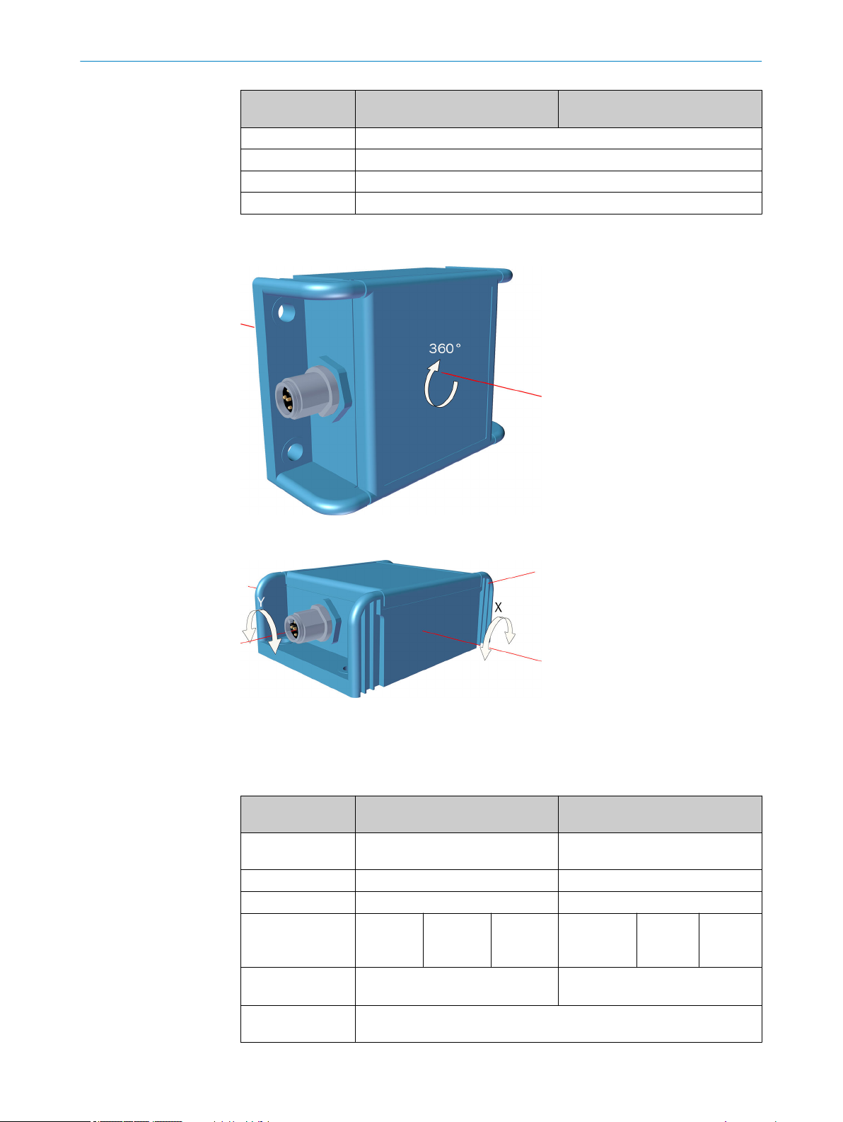
Figure 1: TMS88A measuring axis (large plastic housing)
Figure 2: TMS88A measuring axes (large plastic housing)
4.2 Technical data for TMS88B/TMM88B
Table 3: Technical data for TMS88B/TMM88B
General parame‐
1)
ters
Number of measur‐
ing axes
Measuring ranges 360° ±90°
Resolution 0.01° 0.01°
Accuracy Range
Cross sensitivity
pens
(com
ated)
Temperature coeffi‐
cient (zer
o point)
1 2
0...360°
- Typ. ±0.10° (±0.11%FS)
Typ. ±0.008°/K
TMS88B TMM88B
Typical
±0.15°
Maximum
±0.25°
Range
up to ±60°
o ±80°
up t
Typical
±0.10°
±0.20°
Max. ±0.20° (±0.22%FS)
Maximum
±0.20°
±0.30°
8
OPERATING INSTRUCTIONS | TMS/TMM88, TMS/TMM61 8019054/14IT/2019-06-27 | SICK
Subject to change without notice
Page 9
TECHNICAL DATA 4
General parame‐
1)
ter
s
TMS88B TMM88B
Sampling rate 80 Hz
Limit frequency Typ. 20 Hz, 2nd order (no digital filter) / 0.1 to 25 Hz, 8th order (with digi‐
ilter)
tal f
Operating tempera‐
-40 °C to +80 °C
ture
Properties
Data rates 10 k, 20 k, 50 k, 62.5 k, 100 k, 125 k, 250 k, 500 k, 800 kbit/s, 1 Mbit/s
omatic detection
Aut
Functions Polling of angle, cyclic and synchronized transmission,
al filter (critically damped (default) or Butterworth low pass, 8th
digit
order), configuration via object directory
Electrical parameters
Supply voltage 8 to 36 V DC
Current consump‐
<16 mA @ 24 V
tion
hanical parameters
Mec
CAN connection 1 x 5-pin M12 sensor plug connector (male connector)
Enclosure rating IP65/67
Dimensions /
ght
Wei
Aluminum housing: 58 mm x 90 mm x 31 mm / approx. 200 g
CANopen conformity
CiA DS-301, v4.2.0 Application layer and communication profile
CiA DS-410 Device profile for inclinometer
CiA DSP-305 Layer setting service (LSS) and protocols
CiA DR-303-3 Indicator specification (status LED)
CiA AN-801 Automatic bit-rate detection
1)
All specified angular accuracies apply after a run-in time of 10 min at 25 °C, limit frequency 0.3 Hz,
e calibration accuracy (at 25 °C): ±0.05°
absolut
8019054/14IT/2019-06-27 | SICK
Subject to change without notice
Figure 3: TMS88B measuring axis (aluminum housing)
OPERATING INSTRUCTIONS | TMS/TMM88, TMS/TMM61
9
Page 10

4 TECHNICAL DATA
Figure 4: TMM88B measuring axis (aluminum housing)
4.3 Technical data for TMS88D/TMM88D
Table 4: General parameters for the dynamic inclination sensor
General parameters for the dynamic
inclina
tion sensor
Number of measuring axes 1 2
Measuring ranges 360° ±90°
Resolution 0.01°
Static accuracy
Dynamic accuracy ±0.5° (typical)
Duration of spurious acceleration
ssion (configurable)
suppre
Temperature coefficient (zero point) ±0.01°/K (typical)
General parameters for the IMU
Measuring ranges ±8 g ±250 °/s
Resolution 0.244 mg 0.00875 °/s
In run bias stability – 6 °/h (typical)
Angular random walk (ARW) – 0.2 °⁄√h
Temperature coefficient (zero point) 0.2 mg/K (typical) 0.005 °/s/K (typical)
General parameters
Sampling rate 200 Hz
Operating temperature -40 °C to +80 °C
Properties
Data transmission rates
Functions
Electrical parameters
Supply voltage 8 to 36 V DC
Current consumption 15 mA @ 24 V
Maximum output current 350 mA
Mechanical parameters
Electrical connection
1
2
TMS88D TM88D
±0.3° (typi‐
cal)
±0.5° (ma
mum)
±0.3° (typi‐
cal)
±0.5° (maxi‐
mum)
xi‐
100 to 10000 ms
Acceleration sensor Gyro sensor
10k, 20k, 50k, 100k, 125k, 250k, 500k, 800k bit/s,
1 Mbit/s; A
utomatic detection
Polling of angle, cyclic and synchronized transmission,
terization, sensor fusion filter, digital low pass fil‐
parame
ter (critically damped or Butterworth, 8th order), configu‐
ration via a digital interface
2 x sensor plug connectors, 5-pin M12 (male connector female c
onnector, looped through)
10
OPERATING INSTRUCTIONS | TMS/TMM88, TMS/TMM61 8019054/14IT/2019-06-27 | SICK
Subject to change without notice
Page 11

TECHNICAL DATA 4
General parameters for the dynamic
inclina
tion sensor
1
TMS88D TM88D
Enclosure rating IP67/69
Dimensions of large plastic housing 66 mm x 90 mm x 36 mm
Weight approx. 200 g
CANopen conformity
CiA DS-301, v4.2.0 Application level and communications profile
CiA DS-410 Device profile for inclinometer
CiA DSP-305 Layer setting service (LSS) and protocols
CiA DR-303-3 Indicator specification (status LED)
CiA AN-801 Automatic bit rate detection
1
All specified angular accuracies apply after a run-in time of 10 min. at 25 °C, absolute calibration accu‐
y (at 25 °C): ±0.05°
rac
2
All specified accuracies apply after a run-in time of 10 min. at 25 °C
Figure 5: TMS88D measuring axis (large plastic housing)
Figure 6: TMM88D measuring axes (large plastic housing)
4.4 Technical data for TMS61B/TMM61B
Table 5: Technical data for TMS61B/TMM61B
General parame‐
1)
s
ter
Number of measur‐
ing axes
Measuring ranges 360° ±90°
Resolution 0.01° 0.01°
1 2
TMS61B TMM61B
8019054/14IT/2019-06-27 | SICK
Subject to change without notice
OPERATING INSTRUCTIONS | TMS/TMM88, TMS/TMM61
11
Page 12

4 TECHNICAL DATA
General parame‐
1)
ter
s
Accuracy Range
0...360°
Cross sensitivity
pens
(com
ated)
Temperature coeffi‐
cient (zer
o point)
- Typ. ±0.09° (±0.10%FS)
Typ. ±0.01°/K
TMS61B TMM61B
Typical
±0.15°
Maximum
±0.25°
Range
up to ±60°
up to ±80°
Typical
±0.10°
±0.20°
Max. ±0.45° (±0.50%FS)
Maximum
±0.20°
±0.30°
Sampling rate 80 Hz
Limit frequency Typ. 20 Hz, 2nd order (no digital filter) / 0.1 to 25 Hz, 8th order (with digi‐
ilter)
tal f
Operating tempera‐
-40 °C to +80 °C
ture
Properties
Data rates 10 k, 20 k, 50 k, 62.5 k, 100 k, 125 k, 250 k, 500 k, 800 kbit/s, 1 Mbit/s
omatic detection
Aut
Functions Polling of angle, cyclic and synchronized transmission,
al filter (critically damped (default) or Butterworth low pass, 8th
Digit
order), configuration via object directory
Electrical parameters
Supply voltage 8 to 36 V DC
Current consump‐
<16 mA @ 24 V
tion
hanical parameters
Mec
CAN connection Cable, 5-wire, 0.2 m, with 5-pin M12 male connector
Enclosure rating IP65/67
Dimensions /
ght
Wei
Small plastic housing: 68 mm x 36.3 mm x 20.7 mm / approx. 80 g (with
cable)
CANopen conformity
CiA DS-301, v4.2.0 Application layer and communication profile
CiA DS-410 Device profile for inclinometer
CiA DSP-305 Layer setting service (LSS) and protocols
CiA DR-303-3 Indicator specification (status LED)
CiA AN-801 Automatic bit-rate detection
1)
All specified angular accuracies apply after a run-in time of 10 min at 25 °C, limit frequency 0.3 Hz,
e calibration accuracy (at 25 °C): ±0.05°
absolut
12
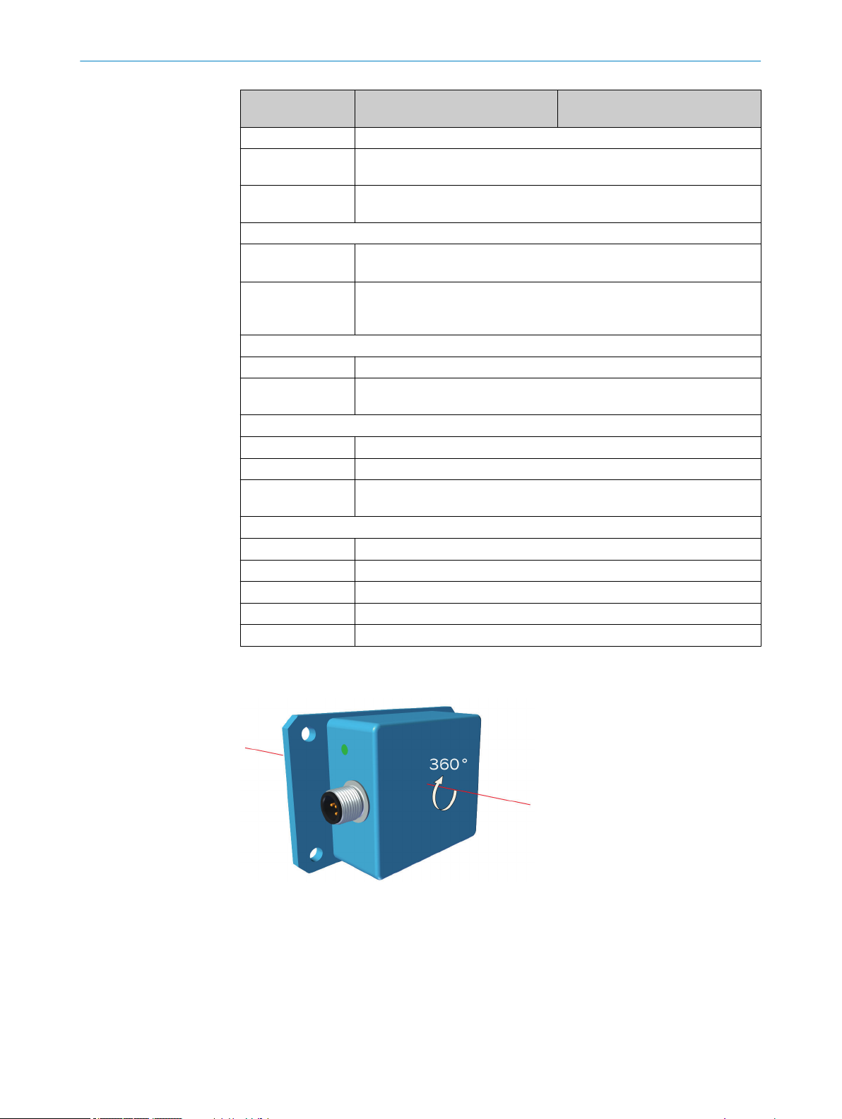
Figure 7: TMS61B measuring axis (small plastic housing)
OPERATING INSTRUCTIONS | TMS/TMM88, TMS/TMM61 8019054/14IT/2019-06-27 | SICK
Subject to change without notice
Page 13

Figure 8: TMS61B measuring axis (small plastic housing)
TECHNICAL DATA 4
8019054/14IT/2019-06-27 | SICK
Subject to change without notice
OPERATING INSTRUCTIONS | TMS/TMM88, TMS/TMM61
13
Page 14

5 T
RANSPORT AND STORAGE
5 Transport and storage
5.1 Transport
For your own safety, please read and observe the following notes:
NOTE
Dama
ge to the device due to improper transport.
■
The device must be packaged for transport with protection against shock and
damp.
■
Recommendation: Use the original packaging as it provides the best protection.
■
Transport should be performed by trained specialist staff only.
■
The utmost care and attention is required at all times during unloading and trans‐
portation on company premises.
■
Note the symbols on the packaging.
■
Do not remove packaging until immediately before you start mounting.
5.2 Transport inspection
Immediately upon receipt in Goods-in, check the delivery for completeness and for any
dama
ge that may have occurred in transit. In the case of transit damage that is visible
externally, proceed as follows:
■
Do not accept the delivery or only do so conditionally.
■
Note the scope of damage on the transport documents or on the transport com‐
pany's delivery note.
■
File a complaint.
5.3 Storage
NOTE
plaints regarding defects should be filed as soon as these are detected. Damage
Com
claims are only valid before the applicable complaint deadlines.
Store the device under the following conditions:
■
ecommend
R
■
Do not store outdoors.
■
Store in a dry area that is protected from dust.
■
So that any residual damp can evaporate, do not package in airtight containers.
■
Do not expose to any aggressive substances.
■
Protect from sunlight.
■
Avoid mechanical shocks.
■
For storage periods of longer than 3 months, check the general condition of all
ation: Use the original packaging.
components and packaging on a regular basis.
14
OPERATING INSTRUCTIONS | TMS/TMM88, TMS/TMM61 8019054/14IT/2019-06-27 | SICK
Subject to change without notice
Page 15

6 Mounting
4 x 45°
58 (2.28)
45 (1.77)
10
(0.39)
75 (2.95)
90 (3.54)
4 x Ø 5.4
(0.21)
90 (
3.54)
75 (2.95)
45 (1.77)
R 2,9
66 (2.60)
68 (2.68)
47.7 (1.88)
57.7 (2.27)
Ø 5 (0.20)
19.7 (0.78)
33.9 (1.33)
36.3 (1.43)
MOUNTING 6
Layout of the fixing holes
The hole
s for screw-mounting the sensor are located in the baseplate of the inclination
sensor (dimensions in mm).
Figure 9: Fixing holes, aluminum housing
8019054/14IT/2019-06-27 | SICK
Subject to change without notice
Figure 10: Fixing holes, large plastic housing
Figure 11: Fixing holes, small plastic housing
NOTICE
e is a risk of damage to the housing if inadequate lifting accessories are used!
Ther
Use suitable washers for plastic housings.
•
OPERATING INSTRUCTIONS | TMS/TMM88, TMS/TMM61
15
Page 16

1
2
3
4
5
2
1
4
5
3
7 CONNECTION
7 Connection
Plug connector pin assignment
TMS/
with a standard 5-pin M12 round male connector (A-coded). TMS/TMM61 inclination
sensors are supplied with a 20 cm long cable at the end of which there is a 5-pin M12
round male connector (A-coded). TMS/TMM88A and TMS/TMM88D inclination sensors
also have a 5-pin M12 female connector (A-coded). The pin assignment corresponds to
CiA DR-303-1.
Table 6: CANopen M12 male connector pin assignment
TMM88A, TMS/TMM88B and TMS/TMM88D inclination sensors are equipped
Pin Signal Pin assignment
1 CAN_SHLD Screen
2 CAN_V+ Supply voltage (+24 V)
3 CAN_GND GND / 0 V / V-
4 CAN_H CAN_H bus cable
5 CAN_L CAN_L bus cable
Table 7: CANopen M12 female connector pin assignment
Pin Signal Pin assignment
1 CAN_SHLD Screen
2 CAN_V+ Supply voltage (+24 V)
3 CAN_GND GND / 0 V / V-
4 CAN_H CAN_H bus cable
5 CAN_L CAN_L bus cable
Bus terminator
NOTE
The inc
16
OPERATING INSTRUCTIONS | TMS/TMM88, TMS/TMM61 8019054/14IT/2019-06-27 | SICK
lination sensors do not have an internal terminator.
Subject to change without notice
Page 17

8 Description of operation
8.1 Function overview
The inclination sensors have a standardized CANopen interface according to CiA
DS-301 and a de
meters can be accessed via the object directory (OD). The individual configuration can
be saved in the internal permanent memory (EEPROM). The following CANopen func‐
tions are available:
■
One or two (TMS/TMM88D) sending data objects (Transmit PDOs), dynamically
mappable to four possible operating modes:
■
■
■
■
■
One service data object (standard SDO)
■
Error messages based on emergency object (EMCY) with support:
■
■
■
■
Monitoring mechanisms: heartbeat as well as node guarding / lifeguarding
■
Save and restore functions for all parameters (store and load parameter field)
■
Status and error display via bi-color LED (according to CiA DR-303-3)
vice profile according to CiA DS-410. All measured values and para‐
Specific request via remote transmit request (RTR) message
Cyclic transmission based on interval time
Event-controlled transmission on inclination change
Synchronous transmission following receipt of a SYNC message
Of the general error register
Of the manufacturer specific status register
Of the pre-defined error field
DESCRIPTION OF OPERATION 8
There are more manufacturer-specific / profile-specific properties in addition to the CiA
DS-301 functionality:
■
Limit frequency (digital filter), freely configurable
■
Sensor fusion filter, freely configurable (TMS/TMM88D only)
■
Configuration of the minimum change in angle for Transmit PDO transmission
event
■
Change in direction of the inclination angle
■
Zero-point setting of the inclination angle
■
Setting of node ID and baud rate via LSS service according to CiA DSP-305
■
Automatic baud rate detection according to CiA AN-801
8019054/14IT/2019-06-27 | SICK
Subject to change without notice
OPERATING INSTRUCTIONS | TMS/TMM88, TMS/TMM61
17
Page 18

Physical layer
Dat
a link layer
e.g., DS401
DSP 410
Device profile for inclinometer
e.g., DS 402
CAN Application Layer (CAL) defined by DS 301
9 CANOPEN INTERFACE
9 CANopen interface
9.1 Communication profile
The CANopen communication profile (documented in CiA DS-301) regulates how the
ices in a CANopen network exchange data.
dev
9.1.1 CANopen in the OSI model
The CANopen protocol is a standardized Layer 7 protocol for the CAN bus. This layer is
ba
sed on t
he CAN Application Layer (CAL).
Figure 12: CANopen in the OSI layers model
NOTE
yers 3 to 6 are not used in the CANopen definition.
La
9.1.2 Communication channels
CANopen features various communication channels (SDO, PDO, Emergency Messages).
T
se channels are formed with the help of the communication object identifier (COB
he
ID). The COB IDs are based on the node IDs of the individual devices on the CANopen
bus (see "Node IDs and COB IDs", page 20).
18
OPERATING INSTRUCTIONS | TMS/TMM88, TMS/TMM61 8019054/14IT/2019-06-27 | SICK
Subject to change without notice
Page 19

LSS, NMT
SDO, PDO, EMGY
Master
Node-ID = 0
Slave
Node-ID = 1 ... 127
Stub cables
P
LC
Trunk cable
End
CANOPEN INTERFACE 9
Figure 13: Master/slave model
a
yer setting services (LSS) are used to set the node ID of the inclination sensor
L
•
(see "Layer setting services (LSS)", page 21).
After this, the inclination sensor can be addressed via the network management
•
services (NMT) (see "Network management: NMT", page 24) and its CANopen
state machine can be switched to the necessary status (Pre-Operational, Opera‐
tional, or Stopped) by the master.
In Pre-Operational status, communication and configuration can be carried out via
•
service data objects (SDO) (see "Service data objects (SDO)", page 28). In Oper‐
ational status, communication is also possible via process data objects (PDO) and
emergency messages (EMGY).
9.1.3 Topology
T-connectors or Y-cables are used to integrate the inclination sensors into the CANopen
t
unk cable (the T-connectors are available as accessories). The trunk cable must be
r
terminated at the end. This is not necessary for the stub cables that are connected to
the sensors.
NOTE
Sinc
e TMS/TMM88A and TMS/TMM88D inclination sensors have a female connector
with looped-through CAN bus, they can also be integrated into the trunk cable without
the need for T-connectors or Y-cables.
8019054/14IT/2019-06-27 | SICK
Subject to change without notice
Figure 14: Example: Network topology
OPERATING INSTRUCTIONS | TMS/TMM88, TMS/TMM61
19
Page 20

9 CANOPEN INTERFACE
9.1.4 Integrating an inclination sensor into a CANopen network
An ESD file makes it easy to link the inclination sensors to a CANopen master.
T
ile contains information on the following features of the inclination sensors:
his f
Information about the device manufacturer
•
Name, type and version number of the device
•
Type and version number of the protocol to be used for this device
•
Inclination sensor default parameters
•
Process data default configuration
•
Figure 15: ESD file integration
9.2 Node IDs and COB IDs
There can be a maximum of 128 devices on a CANopen network: one master and up to
127 slav
The COB IDs (communication object identifiers) of the communication channels are
derived from this ID.
Table 8: Overview of node IDs and COB IDs
Calculation of COB ID
[dec]
hex]
[
0 0 Network management Receive
128
0080h
128 + node ID
0080h + node ID
384 + node ID
0180h + node ID
640 + node ID
0280 + node ID
1408 + node ID
0580h + node ID
1536 + node ID
0600h + node ID
es. Every device has a unique node ID (node address).
ID ranges
[dec]
hex]
[
128
0080h
129 … 255
0081h … 00FFh
385 … 511
0181h … 01FFh
641 to 767
0280h to 02FF
1409 … 1535
0581h … 05FFh
1537 … 1663
0601h … 067Fh
Function Direction from the
point of view of the
sensor
SYNC Receive
gency message Transmit
Emer
ransmit PDO 1 Transmit
T
Transmit PDO 2 (TMS/
h
TMM88D only)
ransmit SDO Transmit
T
eceive SDO Receive
R
Send
20
OPERATING INSTRUCTIONS | TMS/TMM88, TMS/TMM61 8019054/14IT/2019-06-27 | SICK
Subject to change without notice
Page 21

CANOPEN INTERFACE 9
Calculation of COB ID
[dec]
he
x]
[
1792 + node ID
0700h + node ID
2020
07E4h
2021
07E5h
Example
The sensor r
eceives node ID = 5, then sends emergency messages via ID 133, Trans‐
mit PDO 1 via ID 389, and SDOs via ID 1413.
The layer setting services can be used to configure the node ID of the sensor (see
"Layer setting services (LSS)", page 21).
9.3 Layer setting services (LSS)
Layer setting services are supported to set the node ID and the baud rate of the inclina‐
t
ion sensor
The LSS slave is accessed via its LSS address (identity object), which is stored in object
1018h.
.
ID ranges
[dec]
hex]
[
1793 … 1919
0701h … 077Fh
2020
07E4h
2021
07E5h
Function Direction from the
point of view of the
sensor
N
ode guarding, heart‐
beat, boot up
Transmit LSS Transmit
Receive LSS Receive
Transmit
The LSS address comprises:
Manufacturer ID
•
Product code
•
Revision number
•
Serial number
•
The master uses the LSS services to request the individual services that are then exe‐
cuted by the inclination sensor. The LSS telegrams facilitate communication between
LSS master and LSS slave.
The following COB IDs are used:
07E4h = LSS slave to LSS master
07E5h = LSS master to LSS slave
Format of an LSS telegram
NOTE
An LSS t
elegram is always 8 bytes long. Byte 0 contains the command specifier (CS),
followed by 7 bytes for the data. All bytes that are not in use must be set to zero.
Table 9: Format of an LSS telegram
COB-ID Byte 0 Byte 1 Byte 2 Byte 3 Byte 4 Byte 5 Byte 6 Byte 7
CS Data
8019054/14IT/2019-06-27 | SICK
Subject to change without notice
Switch Mode Global
The S
witch Mode Global command switches the configuration mode on or off. The com‐
mand remains unconfirmed and the inclination sensor does not respond.
OPERATING INSTRUCTIONS | TMS/TMM88, TMS/TMM61
21
Page 22

9 CANOPEN INTERFACE
Table 10: Format of the Switch Mode Global command
COB-ID Byte 0 Byte 1 Byte 2 Byte 3 Byte 4 Byte 5 Byte 6 Byte 7
07E5h 04h Mode 00h 00h 00h 00h 00h 00h
Byte 1 mode:
00h = Sw
itches LSS configuration mode off
01h = Switches to LSS configuration mode
Configure Node ID
T
his command is used t
Table 11: Format of the Configure Node ID command
COB-ID Byte 0 Byte 1 Byte 2 Byte 3 Byte 4 Byte 5 Byte 6 Byte 7
07E5h 11h Node ID 00h 00h 00h 00h 00h 00h
o set the node address.
Byte 1 node ID:
01h = node addre
ss 1
…
7Fh = node address 127
Response:
Table 12: Response to the Configure Node ID command
COB-ID Byte 0 Byte 1 Byte 2 Byte 3 Byte 4 Byte 5 Byte 6 Byte 7
07E4h 11h Error
code
Error
ext
00h 00h 00h 00h 00h
end
Byte 1 error code:
00h = Conf
iguration successful
01h = Parameter invalid
FFh = Contains a specific error code
Byte 2 error extend:
The error extension is manufacturer-specific; it is always 00h in the case of the inclina‐
tion sensor.
Configure Bit Timing Parameters
T
his command is used t
Table 13: Format of the Configure Bit Timing Parameters command
COB-ID Byte 0 Byte 1 Byte 2 Byte 3 Byte 4 Byte 5 Byte 6 Byte 7
07E5h 13h 00h Table
o set the baud rate based on a baud rate table.
00h
index
00h 00h 00h 00h
Byte 1 table index from the baud rate table:
Table 14: Baud r
Table index Baud rate Supported
0 1,000 kbit/s Yes
1 800 kbit/s Yes
2 500 kbit/s Yes
3 250 kbit/s Yes
4 125 kbit/s Yes
ate table
22
OPERATING INSTRUCTIONS | TMS/TMM88, TMS/TMM61 8019054/14IT/2019-06-27 | SICK
Subject to change without notice
Page 23

CANOPEN INTERFACE 9
Table index Baud rate Supported
5 100 kbit/s Yes (TMS/TMM88D only)
6 50 kbit/s Yes
7 20 kbit/s Yes
8 10 kbit/s Yes
9 Automatic detection Yes
Response:
Table 15: R
COB-ID Byte 0 Byte 1 Byte 2 Byte 3 Byte 4 Byte 5 Byte 6 Byte 7
07E4h 13h Error
Byte 1 error code:
esponse to the Configure Bit Timing Parameters command
code
Error
extend
00h 00h 00h 00h 00h
00h = Conf
iguration successful
01h = Parameter invalid
FFh = Contains a specific error code
Byte 2 error extend:
The error extension is manufacturer-specific; it is always 00h in the case of the inclina‐
tion sensor.
Store Configuration
T
he command s
aves the configuration.
NOTE
The conf
iguration is not saved in the non-volatile memory (EEPROM). Object 1010h –
Save Parameters must be used in order to do this.
Table 16: Format of the Store Configuration command
COB-ID Byte 0 Byte 1 Byte 2 Byte 3 Byte 4 Byte 5 Byte 6 Byte 7
07E5h 17h 00h 00h 00h 00h 00h 00h 00h
Response:
Table 17: R
COB-ID Byte 0 Byte 1 Byte 2 Byte 3 Byte 4 Byte 5 Byte 6 Byte 7
07E4h 17h Error
esponse to the Store Configuration command
00h 00h 00h 00h 00h
end
code
Error
ext
8019054/14IT/2019-06-27 | SICK
Subject to change without notice
Byte 1 error code:
00h = Stor
e successful
01h = Store Configuration command is not supported
02h = Error occurred during store operation
FFh = Contains a specific error code
Byte 2 error extend:
The error extension is manufacturer-specific; it is always 00h in the case of the inclina‐
tion sensor.
OPERATING INSTRUCTIONS | TMS/TMM88, TMS/TMM61
23
Page 24

9 CANOPEN INTERFACE
Inquire LSS Address Service
This command c
an be used to read out the node ID of the inclination sensor and, from
object 1018h, the manufacturer ID, the product code, the revision number, and the ser‐
ial number.
Table 18: Format of the Inquire LSS Address Service command
COB-ID Byte 0 Byte 1 Byte 2 Byte 3 Byte 4 Byte 5 Byte 6 Byte 7
07E5h CMD 00h 00h 00h 00h 00h 00h 00h
Byte 0 CMD from the command table:
Table 19: C
CMD Parameter Subindex of object 1018h
5Eh Node ID
5Dh Serial number .4
5Ch Revision number .3
5Bh Product code .2
5Ah Vendor ID .1
ommand table
Response:
Table 20: R
COB-ID Byte 0 Byte 1 Byte 2 Byte 3 Byte 4 Byte 5 Byte 6 Byte 7
07E4h CMD Data-X
esponse to the Inquire LSS Address Service command
Data-X Data-X Data-X
(LSB)
(MSB)
00h 00h 00h
NOTE
ata is 4 bytes long in little-endian byte sequence. If fewer than 4 bytes of data are
The d
read out, the remaining bytes are set to 0.
Identify Non-Configured Slave Device
The command is used t
Table 21: Format of the Identify Non-Configured Slave Device command
COB-ID Byte 0 Byte 1 Byte 2 Byte 3 Byte 4 Byte 5 Byte 6 Byte 7
07E5h 4Ch 00h 00h 00h 00h 00h 00h 00h
Response:
Table 22: Response to the Identify Non-Configured Slave Device command
COB-ID Byte 0 Byte 1 Byte 2 Byte 3 Byte 4 Byte 5 Byte 6 Byte 7
07E4h 50h 00h 00h 00h 00h 00h 00h 00h
9.4 Network management: NMT
Network management (NMT) initializes the nodes in a CANopen network. It also adds
the node
There is only one NMT master (network management master) in a CANopen network. All
other devices, including the inclination sensor, are NMT slaves. The NMT master moni‐
tors all devices and can change their status.
s to the network, as well as stopping and monitoring them.
o identify non-configured devices.
24
A PLC or a PC usually serves as the NMT master.
OPERATING INSTRUCTIONS | TMS/TMM88, TMS/TMM61 8019054/14IT/2019-06-27 | SICK
Subject to change without notice
Page 25

9.4.1 CANopen state machine
Like every CANopen slave, the inclination sensor features what is known as a CANopen
s
ate machine. The following statuses can be identified:
t
Table 23: Status of the CANopen state machine
Status Description
Initializing Initialization commences. Both the device application and device
Pre-Operational The inclination sensor is ready for configuration; acyclic communi‐
Operational In this status, the inclination sensor is fully ready for operation and
Stopped In this status, the inclination sensor is not actively communicating
9.4.2 Network management services
CANOPEN INTERFACE 9
communica
switches to Pre-Operational status.
cation can take place via SDO. However, the inclination sensor is
not yet able to commence PDO communication and is not sending
out any emergency messages.
can transmit messages autonomously (PDOs, emergency mes‐
sages).
(althou
guarding).
tion are initialized. After this, the node automatically
gh communication is still being actively monitored via node
NMT services are used to switch between the individual statuses of the CANopen state
mac
. The NMT telegrams for device monitoring use the COB ID 0 and thus have the
hine
highest priority.
Table 24: Format of the NMT telegram
COB-ID Byte 0 Byte 1 Byte 2 Byte 3 Byte 4 Byte 5 Byte 6 Byte 7
00h CCD Node ID 00h 00h 00h 00h 00h 00h
Table 25: Meaning of byte 0
Byte 0, CCD Parameter
01h Start Remote Node
s the inclination sensor to Operational status.
Set
02h Stop Remote Node
s the inclination sensor to Stopped status and stops it communicating
Set
(although communication is still being actively monitored via node guard‐
ing).
80h Enter Pre-Operational
s the inclination sensor to Pre-Operational status. All communication
Set
channels except the PDOs can be used.
81h Reset Node
sets the values of the profile parameters to the default values. After this,
Re
the inclination sensor switches to Reset Communication status.
82h Reset Communication
s the inclination sensor to Reset Communication status. After this, the
Set
inclination sensor switches to Initialization status.
8019054/14IT/2019-06-27 | SICK
Subject to change without notice
OPERATING INSTRUCTIONS | TMS/TMM88, TMS/TMM61
25
Page 26

Switch on or reset
Initialization
Pre-Operational
Operational
Stopped
9 CANOPEN INTERFACE
Transitions between the individual operating statuses
Figure 16: Process diagram of status changes
Table 26: T
Transition Description
1 After switching on, the inclination sensor switches to Initialization status.
2 After Initialization, the inclination sensor automatically switches to Pre-Oper‐
3 and 8 The Start Remote Node command switches the inclination sensor to Opera‐
4 and 7 The Enter Pre-Operational State command resets the inclination sensor to
5 and 6 The Stop Remote Node command switches the inclination sensor to
9, 10, and 11 The Reset Node command switches the inclination sensor to Initialization
12, 13, and 14 The Reset Communication command switches the inclination sensor to Ini‐
9.4.3 Boot-up message
To signal that the device is ready for operation following switching on, a “boot-up mes‐
s
a
permanently linked to the set device address (700h + node ID).
ransitions between operating statuses
at
ional status.
tional status.
-Operational status.
Pre
Stopped status.
status.
zation status.
tiali
ge” is sent out. This message uses the ID of the NMT error control protocol and is
9.4.4 Node guarding and heartbeat
26
OPERATING INSTRUCTIONS | TMS/TMM88, TMS/TMM61 8019054/14IT/2019-06-27 | SICK
The inclination sensor can be monitored permanently with the node guarding protocol
or t
artbeat protocol.
he he
Subject to change without notice
Page 27

CANOPEN INTERFACE 9
NOTE
It is not pos
lel with a single node. If the heartbeat time parameter of object 1017h is not equal to
0, the heartbeat protocol is used.
Node guarding
sible to use the node guarding protocol and the heartbeat protocol in paral‐
The node guar
ding telegram is sent to poll the status of the inclination sensor at regular
intervals. The sensor responds within the response time configured in objects 100Ch
(guard time) and 100Dh (life-time factor).
This time is referred to as the node life time. It is calculated as follows:
“Node life time” = “guard time” x “life-time factor”
If the inclination sensor does not send a response within this time, the connection is
considered to have been lost.
Table 27: Format of the node guarding telegram
COB-ID Byte 0 Byte 1 Byte 2 Byte 3 Byte 4 Byte 5 Byte 6 Byte 7
700h +
node ID
Table 28: Meaning of byte 0
Byte 0, status Parameter
Bit 7 Toggle bit
Bits 6 ... 0 Operating status of the inclination sensor:
Status 00h 00h 00h 00h 00h 00h 00h
The bit c
127 = Pre
5 = Operational
4 = Stopped
0 = Boot Up
hanges its value every time it is polled.
-Operational
Example for an inclination sensor in Operational operating status:
85h, 05h, 85h = no err
or
85h, 05h, 05h = error
NOTE
If node guardin
g is active, the inclination sensor expects to receive a corresponding sta‐
tus query from an NMT master within a certain time frame. If it does not, the slave
switches to Pre-Operational status.
Heartbeat
If the he
artbeat telegram is used, the inclination sensor sends its status autonomously
at cyclic intervals. This can be monitored by every other node in the network.
The heartbeat time is configured with object 1017h.
Table 29: Format of the heartbeat telegram
COB-ID Byte 0 Byte 1 Byte 2 Byte 3 Byte 4 Byte 5 Byte 6 Byte 7
700h +
node ID
Table 30: Meaning of byte 0
Byte 0, status Parameter
Bit 7 Toggle bit
Status 00h 00h 00h 00h 00h 00h 00h
T
hanges its value every time it is polled.
he bit c
8019054/14IT/2019-06-27 | SICK
Subject to change without notice
OPERATING INSTRUCTIONS | TMS/TMM88, TMS/TMM61
27
Page 28

9 CANOPEN INTERFACE
Byte 0, status Parameter
Bits 6 ... 0 Operating status of the inclination sensor:
NOTE
Hear
tbeat has a significant influence on the bus load of the CANopen network but only
generates half the bus load of node guarding.
9.5 Service data objects (SDO)
Service data objects (SDO) form the communication channel through which device
parame
SDOs can be used to transmit data of any length. The data might have to be split into
several CAN messages. An SDO is always transmitted with confirmation, i.e. the receipt
of every message is acknowledged by the receiver.
Transmit SDO and Receive SDO
ters are transmitted. They are used for status queries.
127 = Pre
5 = Operational
4 = Stopped
0 = Boot Up
-Operational
The inc
lination sensor has a Transmit SDO channel and a Receive SDO channel, to
which two CAN identifiers are assigned.
SDO communication corresponds to the client-server model. The inclination sensor
functions as an SDO server.
In its request, the SDO client (e.g., the PLC) specifies the parameter, the access method
(read/write), and the value, if applicable. The inclination sensor executes read or write
access and responds to the request.
The maximum data length of a CAN telegram of 8 bytes is assigned by an SDO as fol‐
lows:
Table 31: Format of the SDO telegram
COB-ID CCD Index Subinde
x
600h +
node ID
Byte 0 Byte 1 Byte 2 Byte 3 Byte 4 Byte 5 Byte 6 Byte 7
Data
The command code (CCD) identifies whether read or write access is required. In the
ev
ent of an error, the data range will contain a 4-byte error code which provides infor‐
mation about the cause of the error.
28
OPERATING INSTRUCTIONS | TMS/TMM88, TMS/TMM61 8019054/14IT/2019-06-27 | SICK
Subject to change without notice
Page 29

Request
R
esponse
CANOPEN INTERFACE 9
Figure 17: Example request/response telegram
In the e
xample, the inclination sensor (ID = 5) receives the read request (CCD = 40h)
for object 1000h from the PLC via ID 0605h (Receive SDO 0600h + inclination sensor
ID).
The inclination sensor responds by sending ID 0585h (Transmit SDO 0580h + inclina‐
tion sensor ID) with feedback (CCD = 43h).
9.6 Process data objects (PDO)
Process data objects (PDO) are used for rapid and efficient data exchange of real-time
d
ta (e.g., I/O data, setpoint values or actual values).
a
PDOs are transmitted without confirmation.
The inclination sensor supports one or two (TMS/TMM88D) transmit PDOs.
8019054/14IT/2019-06-27 | SICK
Subject to change without notice
OPERATING INSTRUCTIONS | TMS/TMM88, TMS/TMM61
29
Page 30

Transmit-PDO
9 CANOPEN INTERFACE
Figure 18: Structure of the Transmit PDO
Table 32: Format of the PDO telegram
COB-ID Data
0180h +
node ID
Byte 0 Byte 1 Byte 2 Byte 3 Byte 4 Byte 5 Byte 6 Byte 7
9.6.1 PDO mapping
The format of the PDO telegram between master and inclination sensor must be agreed
t
ough what is known as PDO mapping. The process data can be arranged at will in
hr
the PDO message. The address (i.e. index and subindex) and the size (number of bits)
from the entry in the object directory are entered in the mapping object for this pur‐
pose.
Example:
Object 1A00h is factory-set to contain the following objects, depending on sensor type:
6010.00h - inclination value, axial (TMS) or longitudinal (TMM)
6020.00h - inclination value, lateral (TMM only)
The content of the objects is transmitted in the Transmit PDO telegram.
Table 33: Example Transmit PDO telegram (TMS)
COB-ID Data
0180h +
node ID
Table 34: Example Transmit PDO telegram (TMM)
COB-ID Data
0180h +
node ID
Byte 0 Byte 1 Byte 2 Byte 3 Byte 4 Byte 5 Byte 6 Byte 7
Inclination value,
axial
Byte 0 Byte 1 Byte 2 Byte 3 Byte 4 Byte 5 Byte 6 Byte 7
Inclination value
udinal
longit
Inclination value
lateral
N
ot used
Not used
30
The following objects can be mapped in the TPDOs:
OPERATING INSTRUCTIONS | TMS/TMM88, TMS/TMM61 8019054/14IT/2019-06-27 | SICK
Subject to change without notice
Page 31

CANOPEN INTERFACE 9
Table 35: Mappable objects
Index Subindex Size Description Format
0x3100 1 16 Euler angle: pitch signed, 0.01°/bit
0x3100 2 16 Euler angle: roll signed, 0.01°/bit
0x3101 1 16 Quaternion: w signed, 1/30000 / bit
0x3101 2 16 Quaternion: x signed, 1/30000 / bit
0x3101 3 16 Quaternion: y signed, 1/30000 / bit
0x3101 4 16 Quaternion: z signed, 1/30000 / bit
0x3102 1 16 Acceleration, x-axis signed, 1/4096g / bit
0x3102 2 16 Acceleration, y-axis signed, 1/4096g / bit
0x3102 3 16 Acceleration, z-axis signed, 1/4096g / bit
0x3103 1 16 Yaw rate, x-axis signed, 7/800°/s /
bit
0x3103 2 16 Yaw rate, y-axis signed, 7/800°/s /
bit
0x3103 3 16 Yaw rate, z-axis signed, 7/800°/s /
bit
0x6010 0 16 Slope long16 signed, 0.01°/bit
0x6020 0 16 Slope lateral16 signed, 0.01°/bit
0x6511 0 8 Temperature signed, 1K/bit
9.6.2 PDO data transmission
The PDOs can be transmitted cyclically or acyclically. This is determined by the Transmit
P
DO and t
Synchronized data transmission
In synchronized data transmission, the process data is transmitted with the SYNC mes‐
sages. The cycle is formed from a multiple of the SYNC messages. The factor can be
between 1 and 240.
Cyclic data transmission
In cyclic data transmission, the inclination sensor sends the PDO at defined intervals.
The associated period duration is configured in object 1800.05h.
Acyclic data transmission
For acyclic data transmission, the inclination sensor is triggered by one of the following
criteria:
Application-specific / device-specific triggering
•
The sending of the PDO is triggered by an event. This event is defined in object
3001h (TPDO 1 only).
On request (RTR telegram)
•
In this case, another bus node (usually the master) requests the process data.
NOTE
For t
he inclination sensor to output the PDO cyclically or acyclically, the transmission
type must be changed in the Transmit PDO in object 1800.02h (see "Transmit PDO –
Transmission type (1800h/1801h)", page 35).
he transmission type defined in its subindex 02.
8019054/14IT/2019-06-27 | SICK
Subject to change without notice
OPERATING INSTRUCTIONS | TMS/TMM88, TMS/TMM61
31
Page 32

9 CANOPEN INTERFACE
9.7 Object directory
The object directory contains all data objects which can be accessed from outside and
h ha
whic
into three parts:
■
■
■
The parameters it contains can be read and written with the standard SDO based on
index and subindex.
The following sections describe all parameters in the object directory of an inclination
sensor including index, subindex, data type, access right and default value (factory set‐
ting). The Storage column indicates whether a parameter can be saved in the internal
permanent memory (write save signature to OD index 1010h/01h).
9.7.1 Communication parameters (to CiA DS-301)
Table 36: Communication parameters in the object directory
Index Subindex Parameter Data type Access Default value Storage
1000h 0 Device type (device profile 410) UNS32 ro 1019Ah/
1001h 0 Error register UNS8 ro 0
1002h 0 Manufacturer status register UNS32 ro 0
1003h Predefined error field
0 Number of error entries UNS32 rw 0
1..5 Error code (oldest error assigned to highest
index)
1005h 0 COB ID sync message UNS32 rw 80h
1008h 0 Device name VSTR const dep. on type
100Ah 0 Software version (“Vxx.yy”) VSTR const dep. on type
100Ch 0 Guard time (multiple of 1 ms) UNS16 rw 0 x
100Dh 0 Life-time factor UNS8 rw 0 x
1010h Save parameters (signature: 's','a','v','e' - 65766173h in subindex 1...4)
0 Highest subindex supported UNS32 ro 4
1 Save all parameters (OD: 0x1000-0x9FFF) UNS32 rw 1
2 Save communication parameters
(OD: 0x1000-0x1FFF)
3 Save application parameters
(OD: 0x6000-0x9FFF)
4 Save manufacturer parameters
(OD: 0x2000-0x5FFF)
1011h Restore default parameters (signature: 'l','o','a','d' - 64616F6Ch in subindex 1...4)
0 Highest subindex supported UNS32 ro 4
1 Restore all parameters (OD: 0x1000-0x9FFF) UNS32 rw 1
2 Restore communication parameters
(OD: 0x1000-0x1FFF)
3 Restore application parameters
(OD: 0x6000-0x9FFF)
4 Restore manufacturer parameters
(OD: 0x2000-0x5FFF)
ve an impact on communication, application and state machines. It is divided
Communication-specific part (index: 0x1000 – 0x1FFF)
Manufacturer-specific part (index: 0x2000 – 0x5FFF)
Profile-specific part (index: 0x6000 – 0x9FFF)
2019Ah
UNS32
UNS32 rw 1
UNS32 rw 1
UNS32 rw 1
UNS32 rw 1
UNS32 rw 1
UNS32 rw 1
ro 0
32
OPERATING INSTRUCTIONS | TMS/TMM88, TMS/TMM61 8019054/14IT/2019-06-27 | SICK
Subject to change without notice
Page 33

CANOPEN INTERFACE 9
Index Subindex Parameter Data type Access Default value Storage
1014h 0 COB ID emergency message UNS32 ro 80h + node
ID
1015h 0 Inhibit time between two EMCY messages (multi‐
ple of 100 µs)
1017h 0 Heartbeat rate time (multiple of 1 ms, 0 deacti‐
va
ted)
1018h Identity object
0 Highest subindex supported UNS8 ro 4
1 Vendor ID (SICK AG ident number) UNS32 ro 01000056h
2 Product code UNS32 ro {dep. on
3
4
Revision number UNS32 ro {dep. on
Serial number UNS32 ro {dep. on
1200h Server SDO1 parameters
0 Highest subindex supported UNS8 ro 2
1 COB ID client > server UNS32 ro 600h + node
2 COB ID server > client UNS32 ro 580h + node
1800h Transmit PDO 1 communication parameters
0 Highest subindex supported UNS8 ro 5
1 COB-ID UNS32 ro 180h + node
2 Transmission type (synchronous / asynchronous
manufac
turer-specific)
3 Inhibit time between two Transmit PDO mes‐
sages (multiple of 100 µs)
4 Compatibility entry UNS8 rw 0 x
5 Event Timer (multiple of 1 ms, 0 deactivated) UNS16 rw 0 x
1801h Transmit PDO2 communication parameters (TMS/TMM88D only)
0 Highest subindex supported UNS8 ro 5
1 COB-ID UNS32 ro 280h + node
2 Transmission type (synchronous / asynchronous
manufac
turer-specific)
3 Inhibit time between two TPDO messages (multi‐
ple of 100 µs)
4 Compatibility entry UNS8 rw 0 x
5 Event timer (multiple of 1 ms, 0 deactivated) UNS16 rw 0 x
1A00h Transmit PDO 1 mapping parameters
0 Highest subindex supported UNS8 ro dep. on type
1 Mapping entry 1, both types: TMS / TMM UNS32 rw 0x60100010 x
2 Mapping entry 2, type: TMS / TMM UNS32 rw 0 /
3 Mapping entry 3 UNS32 rw 0 x
4 Mapping entry 4 UNS32 rw 0 x
UNS16 rw 0 x
UNS16 rw 0 x
type}
type}
type}
ID
ID
ID
UNS8 rw 1 x
UNS16 rw 0 x
x
ID
UNS8 rw 1 x
UNS16 rw 0 x
x
0x60200010
8019054/14IT/2019-06-27 | SICK
Subject to change without notice
OPERATING INSTRUCTIONS | TMS/TMM88, TMS/TMM61
33
Page 34

9 CANOPEN INTERFACE
Index Subindex Parameter Data type Access Default value Storage
5 Mapping entry 5 UNS32 rw 0 x
6 Mapping entry 6 UNS32 rw 0 x
7 Mapping entry 7 UNS32 rw 0 x
8 Mapping entry 8 UNS32 rw 0 x
1A01h Transmit PDO2 mapping parameters (TMS/TMM88D only)
0 Highest subindex supported UNS8 ro 2
1 Mapping entry 1 UNS32 rw 0x31000110 x
2 Mapping entry 2 UNS32 rw 0x31000210 x
3 Mapping entry 3 UNS32 rw 0 x
4 Mapping entry 4 UNS32 rw 0 x
5 Mapping entry 5 UNS32 rw 0 x
6 Mapping entry 6 UNS32 rw 0 x
7 Mapping entry 7 UNS32 rw 0 x
8 Mapping entry 8 UNS32 rw 0 x
1F51h Program download - control
0 Highest subindex supported UNS8 ro 3
1 Firmware range UNS8 rw 1
2 Range for configuration 1
ss for manufacturer only)
(acce
3 Range for configuration 2
ss for manufacturer only)
(acce
UNS8 rw 1
UNS8 rw 1
9.7.1.1 Error register (1001h)
The error register indicates the general error status of the device. Each bit stands for an
er
or group. If a bit is set (= 1), at least one error in this group is currently active. The
r
content of this register is transmitted in every EMCY message. The following error
groups may be encountered:
Table 37: Error register (1001h)
Bit7 Bit6 Bit5 Bit4 Bit3 Bit2 Bit1 Bit0
Manufac‐
turer-spe‐
cific error
Accuracy
Warning
If the device is in error status (at least one error active), this is indicated by bit 0 being
t
. In the event of a communication error (overrun of send/receive buffer, guarding
se
error or CAN controller in passive/busoff mode), bit 4 is set. A profile-specific error (sen‐
sor error) is indicated by bit 5. Bit 7 signals a manufacturer-specific error (EEPROM
error).
9.7.1.2 Manufacturer status register (1002h)
This register indicates the current status of all detectable errors. Each bit represents a
s
ic error. If a bit is set (= 1), this error is currently active. The lower-value 16 bits of
pecif
this register (bits 15 to 0) are transmitted in the first two bits of the manufacturer-spe‐
cific part of each EMCY message as well as in the additional information field (bits 31
to 16) of the predefined error field 1003h.
Profile-spe‐
cific error
Error register (1001h)
Communi‐
cation
error
Not used
At least
one error
active
34
OPERATING INSTRUCTIONS | TMS/TMM88, TMS/TMM61 8019054/14IT/2019-06-27 | SICK
Subject to change without notice
Page 35

Table 38: Manufacturer status register (1002h)
9.7.1.3 Predefined error field (1003h)
Each inclination sensor keeps a list of the five most recent errors that have occurred.
Ent
y 1003.00h contains the number of error entries in the error field. All other
r
subindices contain all of the error states that have occurred in chronological order. The
most recent error is always listed under subindex 01h. The oldest error is located in the
highest available subindex (value of 1003.00h). It is removed from the list first when
more than five errors occur. When an error occurs, a new error entry is added to 1003h
and an EMCY message is also sent by way of notification. An error entry is structured as
follows:
Table 39: Error entry in predefined error field (1003h)
Additional information field (bits 31 to 16) Error code (bits 15 to 0)
Bits 15 to 0 of the manufacturer-specific regis‐
t the time the error occurred)
(a
Bit field
ommunic
C
ation error
CANOPEN INTERFACE 9
Manufacturer status register (1002h)
Bit31...Bit16 Bit15...Bit8 Bit7...Bit0
Not used
Error entry in predefined error field (1003h)
ter 1002h
Bit field
Device error
Communic
0x0000 Error reset or no more errors pending
0x5010 Sensor er
0x5020 Sensor error Y
0x8110 Receive / send buffer overflow
0x8120 CAN warning limit exceeded
0x8130 Node guard event
0x8140 Exit busoff status
Bit field
ation error
r
or / sensor error X
Bit field
Device error
To delete the entire content of the error list, write a value of 0 to entry 1003.00h.
9.7.1.4 Saving (1010h) and restoring (1011h) parameters
Changes that are made to parameters in the object directory are applied immediately.
So t
hat the modified parameters remain active even after a reset, they must be saved
in the internal permanent memory. Writing the Save signature (65766173h) to entry
1010.01h transmits all current parameters from the object directory to the permanent
memory.
To reset the object directory to the factory settings, write the Load signature
(64616F6Ch) to entry 1011.01h. This writes the factory parameters to the permanent
memory. The changes are applied after a Reset Application (NMT command) or a Hard‐
ware Reset (if only a Reset Communication (NMT command) is sent, only the factory
settings of the communication parameters are effective initially).
It is possible to save or load only parts of the object directory by writing the signature to
subindex: 02h, 03h, or 04h.
9.7.1.5 Transmit PDO – Transmission type (1800h/1801h)
The entries 1800.02h/1801.02h are used to define how the sending of the PDO is trig‐
g
er
ed.
8019054/14IT/2019-06-27 | SICK
Subject to change without notice
OPERATING INSTRUCTIONS | TMS/TMM88, TMS/TMM61
35
Page 36

9 CANOPEN INTERFACE
Table 40: Transmit PDO - Transmission type (1800.02h/1801.02h)
Transmis‐
sion type
1...240 Synchronous (cyclic)
253 Transmission exclusively with RTR
254 Asynchronous, manufacturer-specific
9.7.2 Manufacturer-specific part
Table 41: Manufacturer-specific part of the object directory
Index SubindexP
2002h 0 Automatic busoff recovery BOOL rw 0 x
3000h Digital filter settings
3001h Transmit PDO 1, send when angle changes, types TMS88/TMS61
3001h Transmit PDO 1, send when angle changes, types TMM88/TMM61
3002h Sensor fusion configuration (TMS/TMM88D only)
Transmit PDO - Transmission type (1800.02h/1801.02h)
D
escription
Transmission after every 1...240th receipt of the SYNC object
Only synchronized transmission with SYNC possible
y
clic sending and/or sending when angle changes can be activated by means of
C
corresponding configuration.
arameter Data
type
Access Default
value
0 Highest subindex supported UNS16 ro 2
1 Filter type (0=off, 1=Butterworth,
ically damped)
2=crit
2 Digital filter limit frequency
UNS16 rw 2 x
UNS16 rw 2000 x
(100...25000/8000, in mHz)
0 Highest subindex supported UNS16 ro 2
1 Activate/deactivate send when angle
ges (1/0)
chan
2 Minimum change in angle for axial
UNS16 rw 0 x
UNS16 rw 100 x
axis (in °/100)
0 Highest subindex supported UNS16 ro 3
1 Activate/deactivate send when angle
ges (1/0)
chan
2 Minimum change in angle for longitu‐
) axis (in °/100)
dinal (X
3 Minimum change in angle for lateral
UNS16 rw 0 x
UNS16 rw 100 x
UNS16 rw 100 x
(Y) axis (in °/100)
0 Highest subindex supported UNS8 ro 2
1 Activate/deactivate sensor fusion
UNS8 rw 1 x
(1/0)
2 Maximum interference suppression
in ms)
time (
3 Activate/deactivate dynamic gyro off‐
orrection (1/0)
set c
4 Perform gyro offset correction.
UNS16 rw 5000 x
UNS8 rw 1 x
UNS8 wo Writing 1 performs the offset correc‐
tion and permanently saves the cal‐
culated values. The process takes
approx. 2 s.
Storage
36
OPERATING INSTRUCTIONS | TMS/TMM88, TMS/TMM61 8019054/14IT/2019-06-27 | SICK
Subject to change without notice
Page 37

CANOPEN INTERFACE 9
Index SubindexP
3100h Output Euler angles (TMS/TMM88D only)
3101h Output quaternion (TMS/TMM88D only)
3102h Output acceleration sensor raw data (TMS/TMM88D only)
3103h Output yaw rate sensor raw data (TMS/TMM88D only)
5555h Reserved index (for manufacturer access only)
arameter Data
type
5 Level of dynamic offset correction,
value range from 1 (slightly dynamic)
to 10 (very highly dynamic)
0 Highest subindex supported UNS8 ro 2
1 Pitch Euler angle (in °/100) INT16 ro -
2 Roll Euler angle (in °/100) INT16 ro -
0 Highest subindex supported UNS8 ro 4
1 Quaternion scalar part w (in
1/30000)
2 Quaternion vector part x (in
1/30000)
3 Quaternion vector part y (in
1/30000)
4 Quaternion vector part z (in
1/30000)
0 Highest subindex supported UNS8 ro 3
1 Acceleration, x-axis (in 1/4096 g) INT16 ro -
2 Acceleration, y-axis (in 1/4096 g) INT16 ro -
3 Acceleration, z-axis (in 1/4096 g) INT16 ro -
0 Highest subindex supported UNS8 ro 3
1 Yaw rate, x-axis (in 7/800 °/s) INT16 ro -
2 Yaw rate, y-axis (in 7/800 °/s) INT16 ro -
3 Yaw rate, z-axis (in 7/800 °/s) INT16 ro -
UNS8 rw 3 x
INT16 ro -
INT16 ro -
INT16 ro -
INT16 ro -
Access Default
value
Storage
9.7.2.1 Automatic busoff recovery (2002h)
This feature regulates the behavior of the inclination sensor whenever it is in busoff sta‐
tus
. When activated, the inclination sensor can switch out of this status back to the
error-active status with reset error counters. To do this, it must detected 11 consecutive
recessive bits on the bus 128 times.
When deactivated, the inclination sensor remains in busoff status.
9.7.2.2 Digital filter settings (3000h/3002h)
The inclination sensor supports an option to make the continuously generated angle
v
alue mor
e insensitive to external vibration interference. Oscillation/vibration interfer‐
ence up to 0.1 Hz can be suppressed with the configurable 8th order low-pass filter.
The sensor has two digital filters which can be selected according to the area of appli‐
cation in which the sensor is being used.
8019054/14IT/2019-06-27 | SICK
Subject to change without notice
OPERATING INSTRUCTIONS | TMS/TMM88, TMS/TMM61
37
Page 38

0 1 2 3 4 5 6 7 8 9 10
0
5
10
15
Step response 8th order filter
Time [s]
Step
Butterworth, fc = 2 Hz
Butterworth, fc = 0.5 Hz
critically damped, fc = 2 Hz
critically damped, fc = 0.5 Hz
Tilt [°]
9 CANOPEN INTERFACE
Table 42: Filter selection
Filters Configurable
Butterworth 0.1 Hz to 25 Hz Static inclination measurement with high damping against
Critically
damped
The digital filter is selected via entry 3000.01h. The limit frequency is set via object
3000.02h. V
Areas of application
F
equency range
r
ations
vibr
0.1 Hz to 8 Hz Inclination measurement for applications subject to specific
dynamics / without overshoot in the event of changes in
angle combined with good damping
s from 100 (= 0.1 Hz) to 25,000/8,000 (= 25 Hz/8 Hz) are permitted.
alue
Figure 19: Pulse response of both filters
38
OPERATING INSTRUCTIONS | TMS/TMM88, TMS/TMM61 8019054/14IT/2019-06-27 | SICK
Subject to change without notice
Page 39

0.01 0.1 1 10 100
-80
-70
-60
-50
-40
-30
-20
-10
0
10
Frequency [Hz]
Gain [dB]
Gain response 8th order filter
Butterworth, fc = 2 Hz
Butterworth, fc = 0.5 Hz
critically damped, fc = 2 Hz
critically damped, fc = 0.5 Hz
CANOPEN INTERFACE 9
Figure 20: Amplitude characteristic of both filters
The sensor fusion filter uses as a measurand not only the Earth's gravitational field but
also the y
aw rate information from a gyroscope. This enables external accelerations and
vibrations to be suppressed without causing a noticeable delay in the calculation of the
angle information.
Filters Configurable range Areas of application
Sensor fusion 100 ms to 10.000 ms Dynamic applications, measurements while
9.7.2.3 Transmit PDO 1, send when angle changes (3001h)
The event-driven sending of Transmit PDO 1 when the angle changes can be activated
(= 1) and deac
tivated (= 0) via entry 3001.01h.
For activation, the transmission type for Transmit PDO 1 must be set to asynchronous,
manufacturer-specific (1800.02h = 254). Subindices 02h and 03h can be used to set
the minimum necessary change in angle separately for the longitudinal (X) and the lat‐
eral (Y) axis. These two angle values are specified in °/100 (100x angle value) and can
be set to user-defined values starting from 1 (= 0.01°).
If sending when the angle changes is activated, in Operational status, the inclination
sensor will always send Transmit PDO 1 again whenever the inclination value of the lon‐
gitudinal and/or the lateral axis has changed by the angle value set under 3001.02h
and 03h. The difference in angle between the current inclination value and the last
angle value sent with Transmit PDO 1 is constantly calculated and checked.
Every time the status switches to Operational, the inclination sensor signals the current
8019054/14IT/2019-06-27 | SICK
Subject to change without notice
position by sending Transmit PDO 1 once (only if 3001.01h = 1).
acce
lerating, braking, or driving through
curves, measurement with no signal delay time
OPERATING INSTRUCTIONS | TMS/TMM88, TMS/TMM61
39
Page 40

9 C
ANOPEN INTERFACE
NOTE
If minor diff
erences in angle are entered under 3001.02h and 03h, we recommend
activating the digital filter (index 3000h) in order to minimize the effect of vibrations
and thus the frequent sending of Transmit PDO 1.
9.7.3 Profile-specific part (to CiA DS-410)
Table 43: Profile-specific part of the object directory
Index SubindexP
6000h 0 Resolution (multiple of 0.001°) UNS16 ro 10
6010h 0 Inclination value, longitudinal (X axis,
6011h 0 Operating parameter, longitudinal
6012h 0 Default value for longitudinal (X) axis INT16 rw 0 x
6013h 0 Offset value for longitudinal (X) axis INT16 rw 0 x
6014h 0 Difference offset value for longitudi‐
6020h 0 Inclination value, lateral (Y axis, 100x
6021h 0 Operating parameter, lateral (inver‐
6022h 0 Default value for lateral (Y) axis INT16 rw 0 x
6023h 0 Offset value for lateral (Y) axis INT16 rw 0 x
6024h 0 Difference offset value for lateral (Y)
arameter Data
100x angle v
(inversion, zero-point setting)
nal (X
angle value in °)
sion, zero-point setting)
axis
) axis
alue in °)
Access Default
type
INT16 ro -
UNS8 rw 0 x
INT16 rw 0 x
INT16 ro -
UNS8 rw 0 x
T16 rw 0 x
IN
value
Storage
9.7.3.1 Resolution (6000h)
The resolution of all inclination sensors is set to a fixed value of 0.01° (default: 10 *
0.001°). All angle v
alues in the object directory (6010h, 6012h, 6013h, 6014h plus
6020h, 6022h, 6023h, 6024h) must be interpreted as a multiple of 0.01°.
Example:
Angle value = -2370 x 0.01° → -23.70°
9.7.3.2 Longitudinal and lateral angle values (6010h and 6020h)
Up-to-date angle values for the inclination axes can be accessed both via SDO access
t
he object directory (in any device status) and with a Transmit PDO. When zero-point
o t
setting is activated (operating parameters: 6011h and 6021h), the inclination angle is
calculated as follows:
Inclination value = inclination value physically measured + difference offset value +
offset value
When zero-point setting is deactivated:
Inclination value = physically measured inclination value
Operating parameters (6011h and 6021h) describes how the 100x signed 16-bit incli‐
nation value (two's complement) is converted.
Example:
Value range, TMS type: -18,000 ... +17,999 → -180.00° ... +179.99° = 0 ...359.99°
Value range, type TMM: -9,000 ... +9,000 → - 90.00° ... + 90.00°
40
OPERATING INSTRUCTIONS | TMS/TMM88, TMS/TMM61 8019054/14IT/2019-06-27 | SICK
Subject to change without notice
Page 41

CANOPEN INTERFACE 9
9.7.3.3 Operating parameters (6011h and 6021h)
The operating parameter settings of an inclination sensor (6011h and 6021h) can be
used t
setting. These options are deactivated on delivery, i.e., the direction of the angle value
(polarity of the axes) corresponds to the assignment indicated on the device type label.
Table 44: Operating parameters (6011h and 6021h)
9.7.3.4 Zero-point setting: Default value, offset value, difference offset value (60x1/2/3h)
A zero-point setting for the inclination angle can be made using the values for default
v
alue
in the operating parameters (6011h/6021h).
Table 45: Zero-point setting
Default
value
Offset value 6013h
Difference
of
onvert the mathematical sign of the inclination value and also for zero-point
o c
Operating parameters (6011h and 6021h)
Bit7 Bit6 Bit5 Bit4 Bit3 Bit2 Bit1 Bit0
Not used
, offset value, and difference offset value. This setting is only active if bit 1 is set
Value Object Description
f
set value
6012h
6022h
6023h
6014h
6024h
D
efault value for zero-point setting
Value range depending on setting in object 6000h
Calculated offset value when writing to object 6012h or 6022h
alc
ulated offset value = default value with tacc – inclination value
C
physically measured with tacc – difference offset value
tacc: time of write access to default value (6012h,6022h)
Additional offset, independent of object 6012h and 6013h / 6022h
and 6023h
The value entered here is added directly to the current inclination
value.
Zero-point
set
ting
0 = /inac‐
tive
1 = active
Inversion
0 = /inac‐
ive
t
1 = active
9.8 Error messages: Emergency
Emergency messages are used to transmit important internal device errors and CAN
a
tion errors to other nodes on the bus. In the event of one of these errors,
8019054/14IT/2019-06-27 | SICK
Subject to change without notice
communic
the OD entries 1001h (error register), 1002h (manufacturer status register), and
1003h (predefined error field) are updated.
Once an error has been resolved, an emergency message is sent with the error code
0x0000. Any errors that are still pending are signaled in byte 2 (error register) and bytes
3 and 4 of the manufacturer-specific error field. As soon as a device is error-free, it
sends an emergency message containing zeros only. The current device status (PreOperational, Operational, or Stopped) is not affected by the error statuses, except in the
case of guarding errors.
Emergency messages are sent with high priority on the bus. They are always 8 bytes
long:
OPERATING INSTRUCTIONS | TMS/TMM88, TMS/TMM61
41
Page 42

9 CANOPEN INTERFACE
Table 46: Emergency object
Table 47: Emergency error code
Emergency error codes
0x0000 An error has been reset or there are no more errors pending (error register = 0)
0x5010 Sensor error / sensor error X, angle value outside measuring range
0x5020 Sensor error Y, angle value outside measuring range
0x8110 Receive / send buffer overflow, CAN messages lost
0x8120 CAN warning limit exceeded
0x8130 Failure of the guarding master detected (node guard event)
0x8140 Exit busoff status
Emergency object
Byte0 Byte1 Byte2 Byte3 Byte4 Byte5 Byte6 Byte7
Emergency error code Error regis‐
ter
(1001h)
Bit field
Communi‐
cation
error
Manuf
acturer-specific error field
Bit field
Device
error
0x00 0x00 0x00
Table 48: Emergency: Manufacturer-specific error field
Bit field
Device error
0x01 Sensor error, only types: TMS88/TMS61
0x01 Sensor error, X axis, only types: TMM88/TMM61
0x02 Sensor error, Y axis, only types: TMM88/TMM61
0x80 EEPROM error: An error occurred when saving the configuration
Communication error
0x01 CAN warning limit exceeded (too many error frames)
0x02 CAN busoff status reached.
An emerg
0x04 Receive queue overrun, receive buffer overrun, CAN messages lost
0x08 Send queue overrun, send buffer overrun, CAN messages lost
0x80 Guarding error; the failure of the guarding master has been detected (node guard
v
e
ency message is sent after automatically exiting busoff status.
ent)
9.9 Automatic baud rate detection (to CiA AN-801)
Automatic baud rate detection automatically sets the baud rate of the inclination sen‐
sor to t
he current baud rate on the network. For this purpose, following switching on of
the power supply, the inclination sensor is in what is known as listen-only mode. In this
mode, it monitors the messages that are being sent and received on the CAN bus but
does not acknowledge them. This operational status is indicated by the RUN LED flick‐
ering (see also chapter Status LED (to CiA DR-303-3)).
42
In this status, it is testing all available baud rates. When a valid CAN telegram is
received, the correct baud rate is identified and set. After this, the inclination sensor
starts up, logs in with a boot-up message, and switches to Pre-Operational mode.
OPERATING INSTRUCTIONS | TMS/TMM88, TMS/TMM61 8019054/14IT/2019-06-27 | SICK
Subject to change without notice
Page 43

NOTE
In order f
or baud rate detection to function correctly,
telegrams from other bus nodes must be available.
9.10 Status LED (to CiA DR-303-3)
The built-in status LED shows the current device status (RUN LED, green) as well as any
AN communic
C
listed in the following table can be identified based on the color and flashing frequency
of the associated LEDs.
Table 49: Status and error information indicated by the status LED
Status LED
RUN LED LED sta‐
...
...
...
...
...
ERROR LED LED sta‐
...
...
...
...
ation errors that might have occurred (ERROR LED, red). The statuses
CANOPEN INTERFACE 9
escription
D
tus
Off The device is in Reset status or the power supply is
absent.
Flicker‐
ing
Flashing The device is in Pre-Operational status.
Simple
la
sh
f
On The device is in Operational status.
t
us
Off The device is operating without errors.
Simple
fla
sh
Double
fla
sh
On The device is in “busoff” status.
utomatic baud rate detection in progress (active).
A
The device is in Stopped status.
escription
D
CAN controller error counter has reached or exceeded its
warning limit.
The device has detected the failure of the guarding mas‐
ter (node guard event).
8019054/14IT/2019-06-27 | SICK
Subject to change without notice
Key: LED off, LED on, LED flickering (50 ms on/off), / duration: 200 ms
OPERATING INSTRUCTIONS | TMS/TMM88, TMS/TMM61
43
Page 44

Further locations at www.sick.com
Australia
Phone +61 (3) 9457 0600
1800 33 48 02 – tollfree
E-Mail sales@sick.com.au
Austria
Phone +43 (0) 2236 62288-0
E-Mail office@sick.at
Belgium/Luxembourg
Phone +32 (0) 2 466 55 66
E-Mail info@sick.be
Brazil
Phone +55 11 3215-4900
E-Mail comercial@sick.com.br
Canada
Phone +1 905.771.1444
E-Mail cs.canada@sick.com
Czech Republic
Phone +420 2 57 91 18 50
E-Mail sick@sick.cz
Chile
Phone +56 (2) 2274 7430
E-Mail chile@sick.com
China
Phone +86 20 2882 3600
E-Mail info.china@sick.net.cn
Denmark
Phone +45 45 82 64 00
E-Mail sick@sick.dk
Finland
Phone +358-9-25 15 800
E-Mail sick@sick.fi
France
Phone +33 1 64 62 35 00
E-Mail info@sick.fr
Germany
Phone +49 (0) 2 11 53 01
E-Mail info@sick.de
Hong Kong
Phone +852 2153 6300
E-Mail ghk@sick.com.hk
Hungary
Phone +36 1 371 2680
E-Mail ertekesites@sick.hu
India
Phone +91-22-6119 8900
E-Mail info@sick-india.com
Israel
Phone +972-4-6881000
E-Mail info@sick-sensors.com
Italy
Phone +39 02 27 43 41
E-Mail info@sick.it
Japan
Phone +81 3 5309 2112
E-Mail support@sick.jp
Malaysia
Phone +603-8080 7425
E-Mail enquiry.my@sick.com
Mexico
Phone +52 (472) 748 9451
E-Mail mario.garcia@sick.com
Netherlands
Phone +31 (0) 30 229 25 44
E-Mail info@sick.nl
New Zealand
Phone +64 9 415 0459
0800 222 278 – tollfree
E-Mail sales@sick.co.nz
Norway
Phone +47 67 81 50 00
E-Mail sick@sick.no
Poland
Phone +48 22 539 41 00
E-Mail info@sick.pl
Romania
Phone +40 356-17 11 20
E-Mail office@sick.ro
Russia
Phone +7 495 283 09 90
E-Mail info@sick.ru
Singapore
Phone +65 6744 3732
E-Mail sales.gsg@sick.com
Slovakia
Phone +421 482 901 201
E-Mail mail@sick-sk.sk
Slovenia
Phone +386 591 78849
E-Mail office@sick.si
South Africa
Phone +27 (0)11 472 3733
E-Mail info@sickautomation.co.za
South Korea
Phone +82 2 786 6321
E-Mail info@sickkorea.net
Spain
Phone +34 93 480 31 00
E-Mail info@sick.es
Sweden
Phone +46 10 110 10 00
E-Mail info@sick.se
Switzerland
Phone +41 41 619 29 39
E-Mail contact@sick.ch
Taiwan
Phone +886-2-2375-6288
E-Mail sales@sick.com.tw
Thailand
Phone +66 2 645 0009
E-Mail marcom.th@sick.com
Turkey
Phone +90 (216) 528 50 00
E-Mail info@sick.com.tr
United Arab Emirates
Phone +971 (0) 4 88 65 878
E-Mail info@sick.ae
United Kingdom
Phone +44 (0)17278 31121
E-Mail info@sick.co.uk
USA
Phone +1 800.325.7425
E-Mail info@sick.com
Vietnam
Phone +65 6744 3732
E-Mail sales.gsg@sick.com
8019054/14IT/LF_07/2019-06-27/en
SICK AG | Waldkirch | Germany | www.sick.com
 Loading...