

Page 1

TiM781
2D LiDAR sensors
O P E R A T I N G I N S T R U C T I O N S
Page 2

Product described
25
TiM781 (part number 1096807)
Manufacturer
SICK AG
Erwin-Sick-Str. 1
79183 Waldkirch
Germany
Legal information
This work is protected by copyright. Any rights derived from the copyright shall be
reserved for SICK AG. Reproduction of this document or parts of this document is only
permissible within the limits of the legal determination of Copyright Law. Any modifica‐
tion, abridgment or translation of this document is prohibited without the express writ‐
ten permission of SICK AG.
The trademarks stated in this document are the property of their respective owner.
© SICK AG. All rights reserved.
Original document
This document is an original document of SICK AG.
2
O PE R AT I NG IN S TR U CT I ON S | TiM781 8024231//2019-03-29 | SICK
Subject to change without notice
Page 3

Contents
CONTENTS
1 About this document........................................................................ 5
1.1 Information on the operating instructions.............................................. 5
1.2 Explanation of symbols............................................................................ 5
1.3 Further information................................................................................... 6
2 Safety information............................................................................ 7
2.1 Intended use............................................................................................. 7
2.2 Improper use............................................................................................. 7
2.3 Internet protocol (IP) technology.............................................................. 7
2.4 Limitation of liability................................................................................. 7
2.5 Modifications and conversions................................................................ 8
2.6 Requirements for skilled persons and operating personnel.................. 8
2.7 Operational safety and particular hazards.............................................. 9
3 Product description........................................................................... 10
3.1 Scope of delivery....................................................................................... 10
3.2 Setup and dimensions............................................................................. 11
3.3 Display and operating elements.............................................................. 12
3.4 Type code.................................................................................................. 12
3.5 Product identification............................................................................... 13
3.6 Principle of operation............................................................................... 13
3.6.1 Measurement principle........................................................... 13
3.6.2 Range finding........................................................................... 14
3.6.3 Direction measurement.......................................................... 14
3.6.4 Object sizes.............................................................................. 15
3.6.5 Impact of object surfaces on the measurement................... 16
3.6.6 Scanning range........................................................................ 18
3.6.7 Filter.......................................................................................... 19
3.6.8 Calculation of the field size for mobile applications.............. 21
3.6.9 Switching inputs/outputs........................................................ 23
4 Transport and storage....................................................................... 25
4.1 Transport................................................................................................... 25
4.2 Unpacking.................................................................................................. 25
4.3 Transport inspection................................................................................. 25
4.4 Storage...................................................................................................... 25
5 Mounting............................................................................................. 26
5.1 Mounting instructions............................................................................... 26
5.2 Mounting device....................................................................................... 26
5.3 Mutual interference.................................................................................. 26
6 Electrical installation........................................................................ 28
6.1 Prerequisites for safe operation of the device........................................ 28
6.2 Electrical block diagram for commissioning........................................... 31
8024231//2019-03-29 | SICK O PE R AT I NG IN S TR U CT I ON S | TiM781
Subject to change without notice
3
Page 4

CONTENTS
6.3 Wiring notes.............................................................................................. 31
6.4 Connection diagram................................................................................. 31
6.4.1 TiMxxx-21xxxxx......................................................................... 32
6.4.2 USB interface........................................................................... 32
6.5 Connecting the device electrically........................................................... 33
7 Operation............................................................................................ 34
7.1 SOPAS ET................................................................................................... 34
7.1.1 Parameter - network................................................................ 34
7.1.2 Parameter - filters.................................................................... 35
7.2 Field evaluation......................................................................................... 35
7.2.1 Teach-in / Field set selection.................................................. 35
7.2.2 Monitor - field evaluation monitor........................................... 37
7.2.3 Parameter - evaluation cases................................................. 38
7.2.4 Parameter - fields.................................................................... 38
7.3 Measurement data output....................................................................... 40
7.3.1 Monitor - scan view pro........................................................... 40
7.3.2 Telegram................................................................................... 41
8 Maintenance...................................................................................... 43
8.1 Maintenance plan..................................................................................... 43
8.2 Cleaning..................................................................................................... 43
9 Troubleshooting................................................................................. 44
9.1 Detecting and displaying errors............................................................... 44
9.2 Repairs...................................................................................................... 44
9.3 Returns...................................................................................................... 44
9.4 Disposal..................................................................................................... 44
10 Technical data.................................................................................... 45
10.1 Features.................................................................................................... 45
10.2 Performance............................................................................................. 46
10.3 Interfaces.................................................................................................. 46
10.4 Mechanics/electronics............................................................................. 46
10.5 Ambient data............................................................................................. 47
11 Accessories........................................................................................ 48
12 Annex.................................................................................................. 49
12.1 EU declaration of conformity / Certificates............................................. 49
12.2 Licenses.................................................................................................... 49
4
O PE R AT I NG IN S TR U CT I ON S | TiM781 8024231//2019-03-29 | SICK
Subject to change without notice
Page 5
1 About this document
1.1 Information on the operating instructions
These operating instructions provide important information on how to use devices from
SICK AG.
Prerequisites for safe work are:
Compliance with all safety notes and handling instructions supplied.
•
Compliance with local work safety regulations and general safety regulations for
•
device applications
The operating instructions are intended to be used by qualified personnel and electrical
specialists.
NOTE
Read these operating instructions carefully to familiarize yourself with the device and its
functions before commencing any work.
The instructions constitute an integral part of the product and are to be stored in the
immediate vicinity of the device so they remain accessible to staff at all times. Should
the device be passed on to a third party, these operating instructions should be handed
over with it.
ABOUT THIS DOCUMENT 1
These operating instructions do not provide information on operating the machine or
system in which the device is integrated. For information about this, refer to the operat‐
ing instructions of the specific machine.
1.2 Explanation of symbols
Warnings and important information in this document are labeled with symbols. The
warnings are introduced by signal words that indicate the extent of the danger. These
warnings must be observed at all times and care must be taken to avoid accidents, per‐
sonal injury, and material damage.
DANGER
… indicates a situation of imminent danger, which will lead to a fatality or serious
injuries if not prevented.
WARNING
… indicates a potentially dangerous situation, which may lead to a fatality or serious
injuries if not prevented.
CAUTION
… indicates a potentially dangerous situation, which may lead to minor/slight injuries if
not prevented.
NOTICE
… indicates a potentially harmful situation, which may lead to material damage if not
prevented.
NOTE
… highlights useful tips and recommendations as well as information for efficient and
trouble-free operation.
8024231//2019-03-29 | SICK O PE R AT I NG IN S TR U CT I ON S | TiM781
Subject to change without notice
5
Page 6

1 ABOUT THIS DOCUMENT
1.3 Further information
NOTE
Further documentation for the device can be found on the online product page at:
www.sick.com/TiM7xx
•
There, additional information has been provided depending on the product, such as:
Model-specific online data sheets for device variants, containing technical data,
•
dimensional drawing, and specification diagrams
EU declarations of conformity for the product family
•
Dimensional drawings and 3D CAD dimension models in various electronic for‐
•
mats
This documentation, in English and German and other languages if applicable
•
Other publications related to the devices described here
•
Publications dealing with accessories
•
6
O PE R AT I NG IN S TR U CT I ON S | TiM781 8024231//2019-03-29 | SICK
Subject to change without notice
Page 7
2 Safety information
2.1 Intended use
The TiM781 2D LiDAR sensor features a scan plane and is designed for the following
applications:
Detection of objects during continuous output of measurement data as required.
•
Field monitoring of freely defined areas with signaling of field breaches via switch‐
•
ing outputs.
It is suitable for applications which demand precise, non-contact optical measuring con‐
tours and dimensioning. Typical fields of application are, for example, stationary field
protection, area monitoring, access control, mobile applications (navigation and anticollision of mobile platforms).
SICK AG assumes no liability for losses or damage arising from the use of the product,
either directly or indirectly. This applies in particular to use of the product that does not
conform to its intended purpose and is not described in this documentation.
2.2 Improper use
Any use outside of the stated areas, in particular use outside of the technical specifica‐
tions and the requirements for intended use, will be deemed to be incorrect use.
SAFETY INFORMATION 2
The device does not constitute a safety component in accordance with the respec‐
•
tive applicable safety standards for machines.
The device must not be used in explosion-hazardous areas, in corrosive environ‐
•
ments or under extreme environmental conditions.
Any use of accessories not specifically approved by SICK AG is at your own risk.
•
WARNING
Danger due to improper use!
Any improper use can result in dangerous situations.
Therefore, observe the following information:
■
Device should be used only in accordance with its intended use.
■
All information in these operating instructions must be strictly observed.
2.3 Internet protocol (IP) technology
NOTE
SICK uses standard IP technology in its products. The emphasis is placed on availability
of products and services.
SICK always assumes the following prerequisites:
The customer ensures the integrity and confidentiality of the data and rights
•
affected by its own use of the aforementioned products.
In all cases, the customer implements the appropriate security measures, such as
•
network separation, firewalls, virus protection, and patch management.
2.4 Limitation of liability
Relevant standards and regulations, the latest technological developments, and our
many years of knowledge and experience have all been taken into account when com‐
piling the data and information contained in these operating instructions. The manufac‐
turer accepts no liability for damage caused by:
8024231//2019-03-29 | SICK O PE R AT I NG IN S TR U CT I ON S | TiM781
Subject to change without notice
7
Page 8
2 SAFETY INFORMATION
■
Non-adherence to the product documentation (e.g., operating instructions)
■
Incorrect use
■
Use of untrained staff
■
Unauthorized conversions
■
Technical modifications
■
Use of unauthorized spare parts, consumables, and accessories
With special variants, where optional extras have been ordered, or owing to the latest
technical changes, the actual scope of delivery may vary from the features and illustra‐
tions shown here.
2.5 Modifications and conversions
NOTICE
Modifications and conversions to the device may result in unforeseeable dangers.
Interrupting or modifying the device or SICK software will invalidate any warranty claims
against SICK AG. This applies in particular to opening the housing, even as part of
mounting and electrical installation.
2.6
Requirements for skilled persons and operating personnel
WARNING
Risk of injury due to insufficient training.
Improper handling of the device may result in considerable personal injury and material
damage.
■
All work must only ever be carried out by the stipulated persons.
This product documentation refers to the following qualification requirements for the
various activities associated with the device:
■
Instructed personnel have been briefed by the operator about the tasks assigned
to them and about potential dangers arising from improper action.
■
Skilled personnel have the specialist training, skills, and experience, as well as
knowledge of the relevant regulations, to be able to perform tasks delegated to
them and to detect and avoid any potential dangers independently.
■
Electricians have the specialist training, skills, and experience, as well as knowl‐
edge of the relevant standards and provisions to be able to carry out work on elec‐
trical systems and to detect and avoid any potential dangers independently. In Ger‐
many, electricians must meet the specifications of the BGV A3 Work Safety Regu‐
lations (e.g. Master Electrician). Other relevant regulations applicable in other
countries must be observed.
The following qualifications are required for various activities:
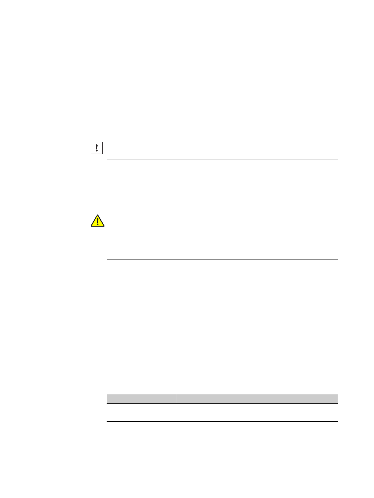
Table 1: Activities and technical requirements
Activities Qualification
Mounting, maintenance
Electrical installation,
device replacement
Basic practical technical training
■
Knowledge of the current safety regulations in the workplace
■
Practical electrical training
■
Knowledge of current electrical safety regulations
■
Knowledge of the operation and control of the devices in their
■
particular application
8
O PE R AT I NG IN S TR U CT I ON S | TiM781 8024231//2019-03-29 | SICK
Subject to change without notice
Page 9
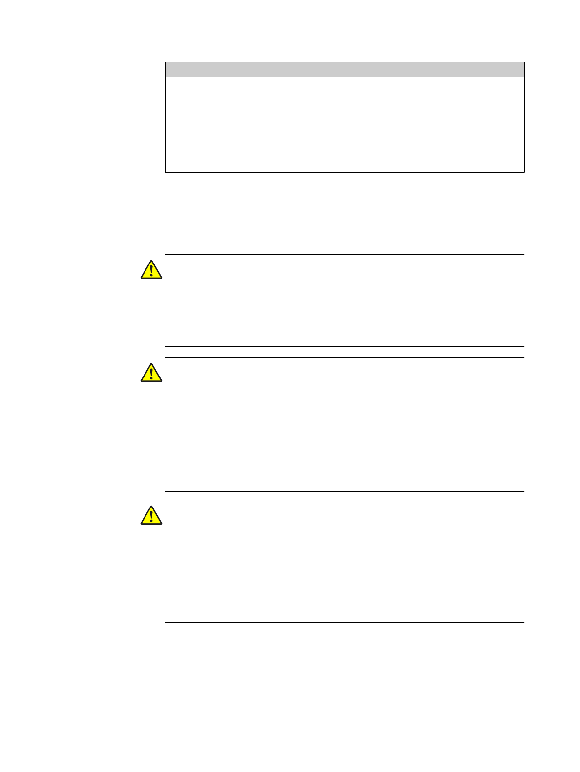
Activities Qualification
Commissioning, configura‐
tion
Basic knowledge of the WindowsTM operating system in use
■
Basic knowledge of the design and setup of the described con‐
■
nections and interfaces
Basic knowledge of data transmission
■
Operation of the device for
the particular application
Knowledge of the operation and control of the devices in their
■
particular application
Knowledge of the software and hardware environment for the
■
particular application
2.7 Operational safety and particular hazards
Please observe the safety notes and the warnings listed here and in other chapters of
this product documentation to reduce the possibility of risks to health and avoid dan‐
gerous situations.
CAUTION
Optical radiation: Laser class 1
The accessible radiation does not pose a danger when viewed directly for up to 100
seconds. It may pose a danger to the eyes and skin in the event of incorrect use.
■
Do not open the housing. Opening the housing may increase the level of risk.
■
Current national regulations regarding laser protection must be observed.
SAFETY INFORMATION 2
WARNING
Electrical voltage!
Electrical voltage can cause severe injury or death.
■
Work on electrical systems must only be performed by qualified electricians.
■
The power supply must be disconnected when attaching and detaching electrical
connections.
■
The product must only be connected to a voltage supply as set out in the require‐
ments in the operating instructions.
■
National and regional regulations must be complied with.
■
Safety requirements relating to work on electrical systems must be complied with.
WARNING
Risk of injury and damage caused by potential equalization currents!
Improper grounding can lead to dangerous equipotential bonding currents, which may
in turn lead to dangerous voltages on metallic surfaces, such as the housing. Electrical
voltage can cause severe injury or death.
■
Work on electrical systems must only be performed by qualified electricians.
■
Follow the notes in the operating instructions.
■
Install the grounding for the product and the system in accordance with national
and regional regulations.
8024231//2019-03-29 | SICK O PE R AT I NG IN S TR U CT I ON S | TiM781
Subject to change without notice
9
Page 10

3 PRODUCT DESCRIPTION
3 Product description
3.1 Scope of delivery
The delivery of the device includes the following components:
Table 2: Scope of delivery
No. of
units
1 Device in the version ordered,
1 Printed safety notes, multilin‐
Component Notes
2 mounting straps, 2 screws
M3 x 4 mm
gual (no. 8021393)
Depending on version.
Without connecting cables.
Quick guide and safety notes for 2D-/3D-LiDAR sen‐
sors
10
O PE R AT I NG IN S TR U CT I ON S | TiM781 8024231//2019-03-29 | SICK
Subject to change without notice
Page 11
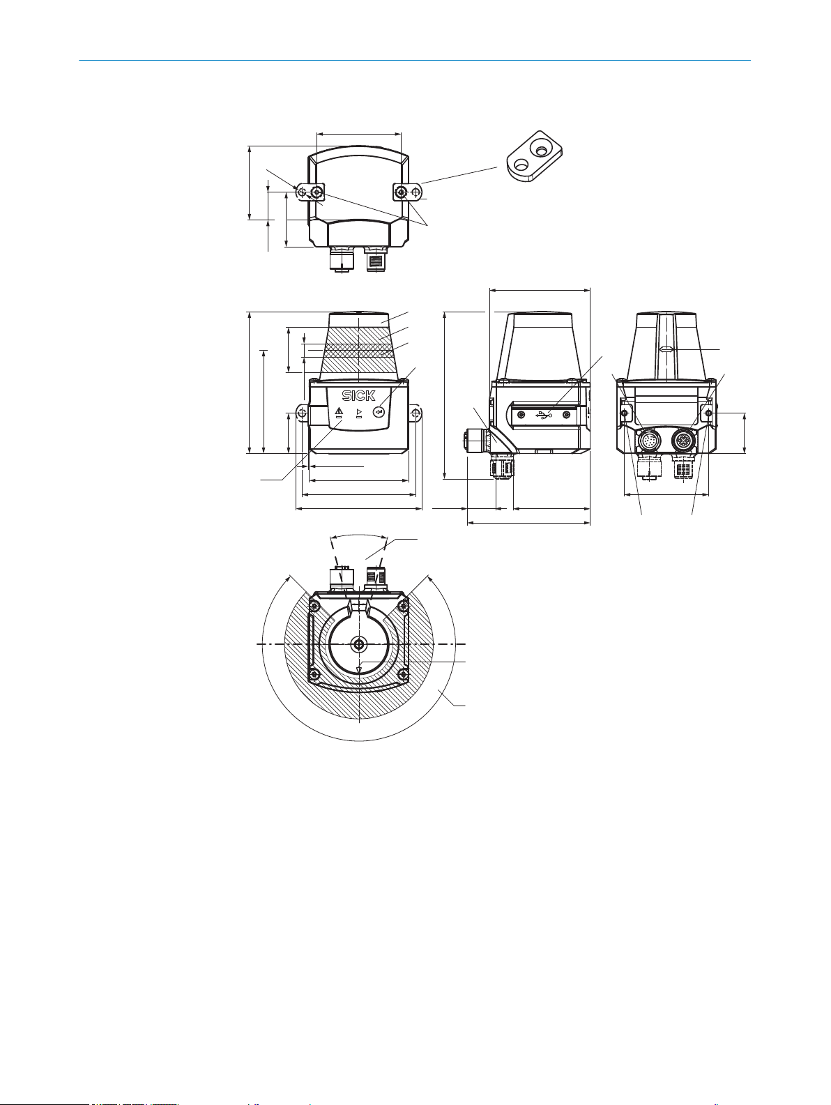
3.2 Setup and dimensions
4
5
3
ß
7
9
à
2 2
225°
‒45°
180°0°
ä
ã
85.75 (3.38)
27.3
[24.4
62.46 (2.46)
60 (2.30)
0.7 (0.03)
[68.8 (2.71)]
[76.25 (3.00)]
61 (2.40)
46.71 (1.84)
74.39 (2.93)
101.12 (3.98)
17.37
(0.68)
51 (2.01)
30°
90°
6
á
8
â
2
1
2 x
51 (2.01)
44.79 (1.76)
16.79
(0.66)
33 (1.3)
[Ø 4.3
(0.17)
]
(0.96)]
(1.07)
8
(0.31)
24.4
(0.96)
PRODUCT DESCRIPTION 3
Figure 1: Structure and dimensions, unit: mm (inch), decimal separator: period
2 x fastening clip with M3 x 4 mm screw (included in scope of delivery)
1
M3 threaded mounting hole, 2.8 mm deep (blind hole thread)
2
Optics cover
3
4
5
6
7
8
9
Receiving range (light inlet)
Transmission range (light emission)
"Teach-in” pushbutton
Red and green LED (status indicators)
Swivel connector unit with electrical connections
Micro USB port, behind the black plaster cover (“Aux interface” connection for configura‐
tion with PC)
Voltage supply connection, digital in/outputs, 12-pin. M12 female connector
ß
Marking for the position of the light emission level
à
Ethernet connection, 4-pin M12 female connector
á
8024231//2019-03-29 | SICK O PE R AT I NG IN S TR U CT I ON S | TiM781
Subject to change without notice
11
Page 12

1 2
3
3 PRODUCT DESCRIPTION
Area in which no reflective surfaces are permitted when the device is mounted
â
Bearing marking to support alignment (90° axis)
ã
270° aperture angle (visual range)
ä
3.3 Display and operating elements
Figure 2: Display and operating elements
Red LED (status indicator)
1
Green LED (status indicator)
2
Teach-in pushbutton
3
Status indicators
LED (red) LED (green) Description
-
O O
-
O O
-
Ö
- - Device without supply voltage
O
Ö
Ö
- Fault
Device ready/monitoring mode
Field breach (if there are lots of field
breaches in a short space of time,
the red LED lighting up might look
like flashing)
Teach-in: start
Teach-in: End of advance warning
phase, 60 seconds Teach-in level
Teach-in: End of teach-in phase
3.4 Type code
12
O PE R AT I NG IN S TR U CT I ON S | TiM781 8024231//2019-03-29 | SICK
O = illuminated; Ö = flashing
The devices of the product family are arranged according to the following type code:
TIM x y z ‒ a b c d e
1 2 3 4 5 6 7 8 9
Table 3: Type code
Position Description Characteristic
1 Device name TIM: Short range 2D-LiDAR sensor
2 Device type 7: Data supplier + field evaluation
3 Output 8: HDDM+, 25 m measuring range, 0.33° angular
resolution, performance professional
4 Housing 1: Housing IP67 without heating
5 Connection 21: Rotating connection unit, 1 x M12 male connec‐
tor, 12-pin, D-coded (Power + I/O); 1x M12 female
connector, 4-pin, A-coded (Ethernet)
7 Application 74: Measurement data supplier and flexible field
evaluation with contour fields and particle filters
Subject to change without notice
Page 13
Position Description Characteristic
TIM781-2174101
1096807
1118 0001
March 2018
1
2
3
4
5
6
8
7
9
25
8 Laser type 1: Pulse power up to 880 mW, pulse width up to
9 Color 01: Gray
NOTE
Not all combinations are possible according to the type code. The available device vari‐
ants can be found online at:
www.sick.com/TiM7xx
•
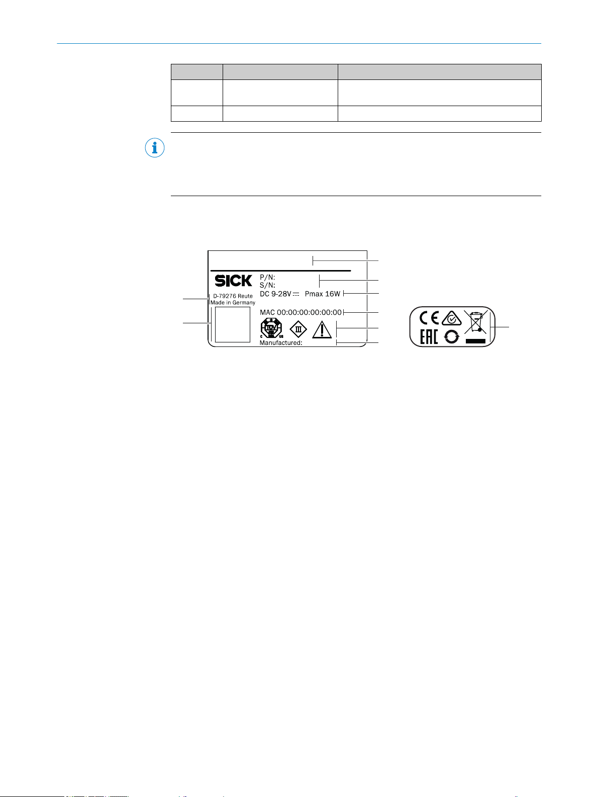
3.5 Product identification
The type label gives information for identification of the product variant.
PRODUCT DESCRIPTION 3
5 ns, pulse rate 1,500 kHz
Type code
1
Part number, serial number
2
Voltage supply, maximum power consumption
3
MAC address
4
Conformity mark/certification mark, symbol: Observe the operating instructions!
5
Production date
6
DataMatrix code with product data (part number, serial number, MAC address)
7
Manufacturer/production location
8
Conformity mark/certification mark
9
3.6 Principle of operation
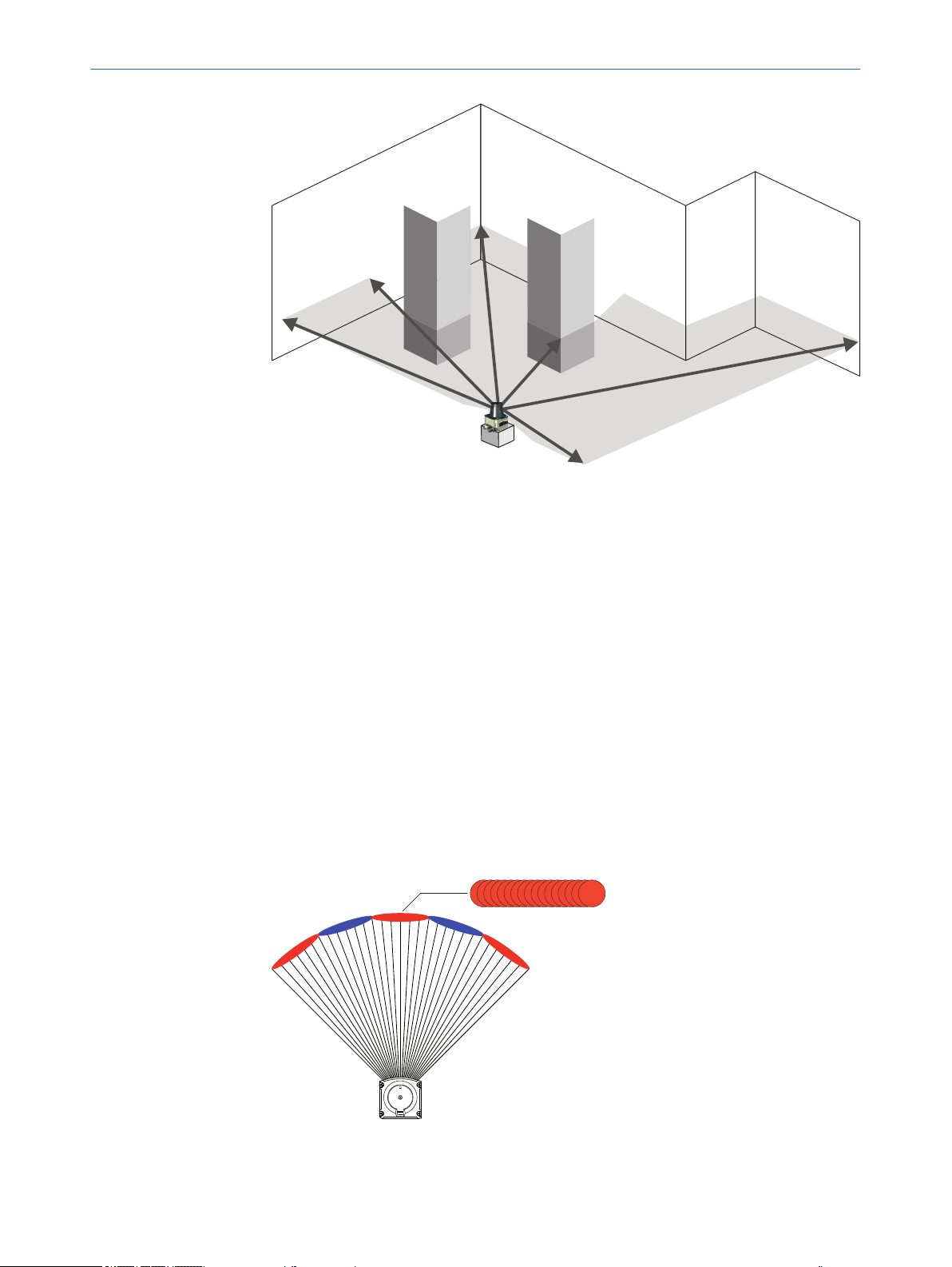
3.6.1 Measurement principle
The device is an opto-electronic LiDAR sensor (laser scanner) that uses laser beams for
non-contact scanning of the outline of its surroundings on a plane. The device mea‐
sures its surroundings in two-dimensional polar coordinates, relative to its measure‐
ment origin. Its measurement origin is marked by a circular indentation in the center of
the optics cover. If a laser beam strikes an object, the position of that object is deter‐
mined in terms of distance and direction.
8024231//2019-03-29 | SICK O PE R AT I NG IN S TR U CT I ON S | TiM781
Subject to change without notice
13
Page 14
1
2
3 PRODUCT DESCRIPTION
Figure 3: Measurement principle of the 2D laser scanner
3.6.2 Range finding
The device emits beams pulsed by a laser diode. If a laser pulse hits an object or per‐
son, it is reflected on the surface of the object or person in question. The reflection is
registered by a photosensitive element in the device receiver. The device uses SICK’s
own HDDM/HDDM+ (High Definition Distance Measurement) technology. With this
measurement process, a measured value is formed by adding together multiple single
pulses. The device calculates the distance from the object based on the elapsed time
that the light requires between emitting the beam and receiving the reflection. Radar
systems apply this “pulse time-of-flight measurement” principle in a similar way.
3.6.3 Direction measurement
The device uses a rotating mirror to deflect the emitted laser beams, thereby scanning
its surroundings in a circular pattern. The measurements are triggered internally by an
encoder in regular angle increments.
The measuring procedure uses the averaging from multiple pulses to determine individ‐
ual measured values. A measuring point is the average value of several measurements
combined.
14
Device
1
Laser pulse
2
O PE R AT I NG IN S TR U CT I ON S | TiM781 8024231//2019-03-29 | SICK
Subject to change without notice
Page 15

3.6.4 Object sizes
1
2
PRODUCT DESCRIPTION 3
As the distance from the device increases, the laser beam expands. As a result, the
diameter of the light spot on the surface of the object increases.
Figure 4: Beam expansion
Expanded laser beam
1
Optical axis
2
Values required to calculate the light spot size:
Light spot size on the device cover: 7 mm (rounded up)
•
Divergence of 1 light spot: 0.49 deg (8.6 mrad)
•
HDDM+ supplement (1 spot comprises several superimposed individual pulses):
•
0.33 deg (5.8 mrad)
Formula for calculating the light spot width:
(Light spot divergence [mrad] + HDDM+ supplement [mrad]) x distance [mm] + light
spot size on the device cover [mm] = light spot width [mm]
Example calculation of the light spot width at a distance of 25 m (25,000 mm):
(8.6 mrad +5.8 mrad) * 25,000 mm +7 mm = 367 mm
Formula for calculating the height of the light spot:
Light spot divergence [mrad] x Distance [mm] + Light spot height at the n device cover
[mm] = Light spot width [mm]
Example calculation of the light spot height at a distance of 25 m (25,000 mm):
8.6 mrad * 25,000 mm +7 mm = 222.0 mm
NOTE
For reliable measurement, in particular when using the device to output measured val‐
ues, the laser needs to hit the object several times. Therefore, the object either needs
to be larger than the minimum object size, or both the LiDAR sensor and the object
must not be moving.
8024231//2019-03-29 | SICK O PE R AT I NG IN S TR U CT I ON S | TiM781
Subject to change without notice
15
Page 16

Size in mm (inch) 1
0
5
(16.4)
20
(65.6)25(82.0)
10
(32.8)
Distance in m (ft) 2
500
(19.7)
0
100
(3.9)
300
(11.8)
400
(15.7)
15
(49.2)
200
(7.9)
3
4
5
3 PRODUCT DESCRIPTION
3.6.5 Impact of object surfaces on the measurement
Figure 5: Minimum object size
Size in millimeters (inc)
1
Distance in meters (feet)
2
Minimum object size
3
Light spot width
4
Light spot height
5
Remission value
Remission is the ability of a material to reflect light. The remission value correlates with
the amount of laser light emitted by the LiDAR sensor which is reflected by an object
(see Lambert’s law).
Shiny surfaces have different remission values at the same distance with different
angles of impact. In the case of shiny surfaces, maximum remission is achieved when
the beam makes vertical impact.
Matt and dull surfaces have diffuse remission. Therefore, they exhibit similar relative
remission values with the same angle of impact regardless of the distance from the
zero point.
Table 4: Typical remission values of frequently used materials
Material Typ. relative remission value
Rubber tires (vulcanized, black) 2%
Foam rubber (black) 2.4%
Photographic board (black, matte) 10%
Cardboard (gray) 20%
Wood (untreated fir, soiled) 40%
PVC (gray) 50%
Paper (white, matte) 80%
Plaster (white) 100%
Aluminum (black anodized) 110 … 150%
16
O PE R AT I NG IN S TR U CT I ON S | TiM781 8024231//2019-03-29 | SICK
Subject to change without notice
Page 17

PRODUCT DESCRIPTION 3
Material Typ. relative remission value
Steel (stainless, shiny) 120 … 150%
Steel (high gloss) 140 … 200%
Reflection
Most surfaces produce a diffuse reflection of the laser beam in all directions. The struc‐
ture (smooth or rough), shape (flat or curved), and color (light or dark) of the surface
determine how well the laser beam is reflected.
On very rough surfaces, part of the energy is lost due to shadowing. Curved surfaces
produce a higher diffusion. Dark surfaces reflect the laser beam worse than light ones
(brilliant white plaster reflects approx. 100% of the light, while black foam rubber
reflects approx. 2.4%). The aforementioned surface characteristics can reduce the
scanning range of the device, in particular for surfaces with low remission values.
Figure 6: Reflection of light on the surface of the object
Angle of reflection
The angle of reflection corresponds to the angle of incidence. If the laser beam hits a
surface at right angles, the energy is optimally reflected. If the laser beam hits a sur‐
face at an oblique angle, energy and range are lost accordingly.
Figure 7: Angle of reflection
Retroreflection
If the reflective energy is greater than 100%, the beam is not reflected diffusely in all
directions; instead it is reflected in a targeted way (retroreflection). Thus a large part of
the emitted energy can be received by the laser distance measurer. Plastic reflectors
(cat’s eyes), reflective tape, and triple prisms have these properties.
8024231//2019-03-29 | SICK O PE R AT I NG IN S TR U CT I ON S | TiM781
Subject to change without notice
17
Page 18

3 PRODUCT DESCRIPTION
Figure 8: Retroreflection
Reflective surfaces
The laser beam is almost completely deflected on reflective surfaces. This means that
an object hit by the deflected beam may be detected instead of the reflective surface.
Figure 9: Specular surfaces
Small objects
Objects that are smaller than the diameter of the laser beam cannot reflect the laser
light’s full energy. The portion of the light beam that does not reach the object is lost. If
all of the light reflected to the sensor is insufficient, the object may not be detected.
The portion of the light that does not reach the front object can be reflected by a larger
object in the background. If all of the light reflected to the sensor is sufficient, this
object is detected.
Figure 10: Object smaller than the laser beam diameter
3.6.6 Scanning range
The scanning range of the device depends on the remission of the object to be
detected. The better a surface reflects the incident beam back to the device, the
greater the scanning range of the device.
18
O PE R AT I NG IN S TR U CT I ON S | TiM781 8024231//2019-03-29 | SICK
Subject to change without notice
Page 19

0
10
20
30
50
60
40
Object remission in % 1
Measuring range in m (ft) 2
0 20
(65.6)
70
90
100
80
10
(32.8)
15
(49.2)
30
(98.4)
5
(16.4)
25
(82.0)
PRODUCT DESCRIPTION 3
Figure 11: Scanning range rate as a function of object remission
Object remission in percent
1
Measuring range in meters (feet)
2
3.6.7 Filter
3.6.7.1 Particle filter
8024231//2019-03-29 | SICK O PE R AT I NG IN S TR U CT I ON S | TiM781
Subject to change without notice
The device has digital filters for pre-processing and optimizing the measured distance
values. They enable the device to be adapted to meet the specific requirements of the
respective application.
The filters can be combined without restrictions. If several filters are active, then the
filters are applied sequentially to the results of the preceding filter. The processing
sequence is as follows:
Particle filter
•
Median filter
•
Average filter
•
The active filter functions affect the output measured values. It is not possible to recal‐
culate the original measured values from the filtered output values. For this reason, cer‐
tain combinations of filters might not be advisable.
A particularly effective way to reduce the data in a scan (reduction of measurement
points) is to restrict the scan range (“Data output” > “Output range”) or the media filter.
The particle filter blanks small, irrelevant reflection pulses in dusty environments and in
rain or snow which are caused by dust particles, raindrops, snowflakes or the like. In
doing so, successive scans are continuously evaluated in order to detect static objects.
19
Page 20

!
"
3 PRODUCT DESCRIPTION
3.6.7.2 Median filter
Figure 12: Without the particle filter: Violation
of the contour due to dust particles in the
vicinity of the object.
Figure 13: Using the particle filter: The
response to dust particles in the field is
delayed by one scan. Particles can thereby be
blanked.
This filter is suitable for excluding individual outliers from the calculation of an average
value.
The values included in the calculation are defined using a 1 x 3 matrix :
3 measured values,consisting of the distance values of a point and its two adjacent
points in the scan, are sorted by size.
The measured value in the middle of this sequence is output as the distance value,
along with its remission value.
The calculation and output of the media values are done statically.
By activating the media filter, 3 distance values within a scan can be reduced to one
output value, which reduces the number of output values to 1/3 compared to the unfil‐
tered scan.
Table 5: Example: Median for scan 1 and 2
Angle (distance values in mm)
Scan 1 2 3 4 5 6 7 8 ...
1 850 852 851 849 850 850 851 850 ...
Scan 1 output value 850 | 851 | 852 849 | 850 | 850 ...
2 849 850 850 853 852 852 850 851 ...
Scan 2 output value 849 | 850 | 850 852 | 852 | 852 ...
... ... ... ... ... ... ... ... ... ...
3.6.7.3 Average filter
20
O PE R AT I NG IN S TR U CT I ON S | TiM781 8024231//2019-03-29 | SICK
The sliding average filter smooths the distance value. It does this by calculating the
arithmetic mean from several scans of the same point. The number of scans can be
configured (maximum 4 scans).
Table 6: Example: Average filter over 5 scans
Angle (distance values in mm)
Scan 1 2 3 4 5 6 7 8 9 …
1 0 0 1100 1100 1150 1150 1380 1380 0 …
2 0 0 1200 1200 1190 950 1500 1500 0 …
3 0 0 1150 1450 1200 1200 1450 1450 0 …
4 0 0 1170 1170 1220 1220 1470 1150 0 …
Subject to change without notice
Page 21

PRODUCT DESCRIPTION 3
Angle (distance values in mm)
Scan 1 2 3 4 5 6 7 8 9 …
1 Output value
(scan 1-4)
5 0 0 0 1110 1150 1150 1380 1380 0 …
2. Output value
(scan 2-5)
6 0 0 1200 1210 1190 0 1500 1500 0 …
3. Output value
(scan 3-6)
7 0 730 1150 0 1200 1200 1450 1450 0 …
4. Output value
(4-7)
… … … … … … … … … … …
Individual outliers (shown in bold in the table) influence the average value.
Once the measured value telegram has been confirmed, the first measured value is not
output until after the configured number of scans. Therefore, there is always a time
delay equivalent to the number of scans configured for averaging. The digit of the first
scan included in the averaging calculation is always output in the scan counter. Invalid
distance values (= 0) are not included in the averaging calculation, so that in these
places a smaller number of scans is used in the division calculation.
0 0 1155 1230 1190 1130 1450 1370 0 …
0 0 1173 1225 1190 1130 1450 1370 0
0 0 1173 1235 1190 1190 1450 1370 0
0 730 1173 1163 1190 1190 1450 1370 0
Based on a scanning frequency of 15 Hz, a measured value is generated every 67 ms .
The time delay affecting data output results from this base value multiplied by the num‐
ber of averaging operations (e.g., 2 averagings = 134 ms, 10 averagings =670 ms).
3.6.8 Calculation of the field size for mobile applications
In order to prevent collisions between vehicles, and between vehicles and fixed objects,
the switching field must have sufficient length and width.
To calculate the switching field length, you need to take into consideration the stopping
distance of the vehicle. This comprises the following:
the braking distance, which can be found in the vehicle documentation
•
the distance covered during the vehicle control’s response time, which can be
•
found in the vehicle documentation
The distance covered during the response time of the LiDAR sensor, "Technical
•
data", page 45.
NOTE
We recommend adding a supplement of at least 100 mm to the protective field
•
length in order to stop the vehicle before a possible collision.
If retro-reflectors are situated in the path of the vehicles, or if you anticipate that
•
the braking force of the vehicle will diminish over time, you may, under certain cir‐
cumstances, need to increase the recommended supplement.
The width of the switching field should cover the vehicle width. You should also
•
configure a supplement of at least 100 mm on every side.
Height of the scan plane
The recommended mounting height for mobile applications is at least 150 mm.
8024231//2019-03-29 | SICK O PE R AT I NG IN S TR U CT I ON S | TiM781
Subject to change without notice
21
Page 22

1
2
3
4
PRODUCT DESCRIPTION
3
3.6.8.1 Switching field length
You must configure the switching field so that a minimum distance to the vehicle is
maintained at all times. This ensures that a vehicle monitored by the LiDAR sensor
stops before an object is reached. You can define multiple monitoring cases each with
different switching fields. These can be switched over dynamically via static control
inputs, for example to adjust the switching field size based on the vehicle speed.
In this kind of application, you must calculate the switching field sizes (in particular the
switching field lengths) for all speeds.
The switching field length SL can be calculated using the following formula (guideline
values based on a pixel calculation):
SL = SA + ZG + ZR + ZB
SA = Stopping distance
ZG = General safety supplement for the LiDAR sensor = 100 mm
ZR = Supplement for application-related influences or the selected application parame‐
ters
ZB = Supplement for the decreasing braking force of the vehicle. This can be obtained
from the relevant vehicle documentation, or alternatively: 10% of the stopping distance.
Stopping distance SA
The stopping distance comprises the vehicle’s braking distance and the distance cov‐
ered during the response time of the LiDAR sensor and the vehicle control’s response
time.
Figure 14: Stopping distance
S
1
2
3
4
A
S
AnF
S
AnS
S
Br
NOTE
Please note that a vehicle’s braking distance does not increase linearly with increasing
speed, but rather in a squared relationship. This is particularly important if you switch
between different-sized switching fields depending on the speed.
22
How to calculate the stopping distance SA:
SA = S
S
AnF
+ S
AnS
+ S
Br
AnF
= The distance covered during the vehicle control’s response time, which is speci‐
fied in the vehicle documentation
S
= The distance covered during the response time of the LiDAR sensor
AnS
O PE R AT I NG IN S TR U CT I ON S | TiM781 8024231//2019-03-29 | SICK
Subject to change without notice
Page 23

PRODUCT DESCRIPTION 3
SBr = The braking distance, found in the vehicle documentation
The distance S
the response time of the LiDAR sensor
•
the maximum speed of the vehicle in your mobile application
•
covered during the response time of the LiDAR sensor depends on:
AnS
For more information on the response time TS of the LiDAR sensor, see "Technical data",
page 45.
How to calculate the distance S
covered during the response time of the LiDAR sen‐
AnS
sor:
S
= TS × V
AnS
max
TS = Response time of the LiDAR sensor
V
Maximum speed of the vehicle, from the relevant vehicle documentation
max
The response time TS of the LiDAR sensor depends on:
the base response time of the LiDAR sensor
•
whether multiple sampling is set
•
the filter settings (e.g., particle filter).
•
ZR supplement
This supplement must be determined on an application-specific basis and taken into
account appropriately. The following factors can make it necessary to use a supple‐
ment: reflectors or shiny objects on the scan plane, multi-echo analysis, blanking size,
device filter (e.g., particle filter).
3.6.8.2 Switching field width
The width of the switching field must cover the width of the vehicle and take into
account the supplements for the measurement error.
The switching field width SB can be calculated using the following formula (guideline
values based on a pixel calculation):
SB = FB + 2 × (ZG + ZR)
FB = Vehicle width
ZG = General safety supplement for the LiDAR sensor = 100 mm
ZR = Supplement for application-related influences or the selected application parame‐
ters
3.6.9 Switching inputs/outputs
Switching inputs
The four digital switching inputs activate one of the 16 field sets in a binary combina‐
tion as an evaluation case. The inputs are decoupled from the supply voltage of the
device. They have a common reference point (INGND), meaning they are not decoupled
from one another.
Switching behav‐
ior
Properties Opto-decoupled
Electrical values Low: Ue ≤ 2 V; Ie ≤ 0.3 mA
Current to the input starts the assigned function in the device. (Default:
active high level, debounce 10 ms)
Switchable with an electronic switch (PNP output) or mechanical switch
High: 8 V ≤ Ue ≤ 32 V; 0.7 mA ≤ Ie ≤ 5 mA
8024231//2019-03-29 | SICK O PE R AT I NG IN S TR U CT I ON S | TiM781
Subject to change without notice
23
Page 24

3 PRODUCT DESCRIPTION
Switching outputs
Switching behav‐
ior
Properties Short-circuit protected and temperature protected
Electrical values 0 V ≤ Ua ≤ U
PNP switching against supply voltage UV
OUT 1 ... OUT 3:
Resting level: High (no field breach), working level: Low (field breach)
Response time: 134 ms ... 30 s (configurable via SOPAS ET ), holding
time: 0 ms ... 10 s (configurable via SOPAS ET)
OUT 4:
Resting level: High (device ready),
working level: Low (error), low pulse (15 Hz, index, corresponds to mea‐
surement at 90°)
Not electrically isolated from supply voltage U
V
(UV –1.5 V) ≤ Ua ≤ UV at Ia ≤ 100 mA
v
Longer connecting cables at the switching outputs of the device should be avoided due
to the resulting fall in voltage. This is calculated as follows:
Δ U = (2 x length x current) : (conductance value x cross-section)
Conductance value for copper: 56 m/Ω mm2.
Assignment of infringed fields - switching outputs
Fields of a field set Switching outputs
OUT 1 OUT 2 OUT 3
Fields 1, 2, and 3 infringed Active Active Active
Fields 2 and 3 infringed Deactivated Active Active
Field 3 infringed Deactivated Deactivated Active
All fields free Deactivated Deactivated Deactivated
Field 1: inner, field 2: center, field 3: outer
Active: in working position; deactivated: in resting position
Output level: The level of the switching outputs OUT 1 ... OUT 3 is active low (in resting
position: high, in working position: low (field infringed)).
All fields of a field set are also deemed to be infringed during switching on, booting, in
the event of an error, and when the device is switched off.
The OUT 4 switching output works with the following levels:
Function Level
Device Ready High
Index signal (15 Hz), corresponds to measure‐
ment at 90°
Fault Low
Low peaks
24
O PE R AT I NG IN S TR U CT I ON S | TiM781 8024231//2019-03-29 | SICK
Subject to change without notice
Page 25

4 Transport and storage
4.1 Transport
For your own safety, please read and observe the following notes:
NOTICE
Damage to the product due to improper transport.
■
The device must be packaged for transport with protection against shock and
damp.
■
Recommendation: Use the original packaging as it provides the best protection.
■
Transport should be performed by trained specialist staff only.
■
The utmost care and attention is required at all times during unloading and trans‐
portation on company premises.
■
Note the symbols on the packaging.
■
Do not remove packaging until immediately before you start mounting.
TRANSPORT AND STORAGE 4
4.2
Unpacking
■
Before unpacking, it may be necessary to equalize the temperature to protect the
device from condensation.
■
Handle the device with care and protect it from mechanical damage.
■
Remove the protective caps on the electrical connections immediately before con‐
necting the connecting cable to prevent dirt and water from entering.
4.3 Transport inspection
Immediately upon receipt in Goods-in, check the delivery for completeness and for any
damage that may have occurred in transit. In the case of transit damage that is visible
externally, proceed as follows:
■
Do not accept the delivery or only do so conditionally.
■
Note the scope of damage on the transport documents or on the transport com‐
pany's delivery note.
■
File a complaint.
NOTE
Complaints regarding defects should be filed as soon as these are detected. Damage
claims are only valid before the applicable complaint deadlines.
4.4 Storage
Store the device under the following conditions:
■
Recommendation: Use the original packaging.
■
Do not store outdoors.
■
Store in a dry area that is protected from dust.
■
So that any residual damp can evaporate, do not package in airtight containers.
■
Do not expose to any aggressive substances.
■
Protect from sunlight.
■
Avoid mechanical shocks.
■
Storage temperature: see "Technical data", page 45.
■
Relative humidity: see "Technical data", page 45.
■
For storage periods of longer than 3 months, check the general condition of all
components and packaging on a regular basis.
8024231//2019-03-29 | SICK O PE R AT I NG IN S TR U CT I ON S | TiM781
Subject to change without notice
25
Page 26

5 MOUNTING
5 Mounting
5.1 Mounting instructions
Observe the technical data.
•
Protect the sensor from direct and indirect sunlight.
•
To prevent condensation, avoid exposing the device to rapid changes in tempera‐
•
ture.
The mounting site has to be designed for the weight of the device.
•
The device can be mounted in any position.
•
It should be mounted so that it is exposed to as little shock and vibration as possi‐
•
ble. Optional mounting accessories are available, see "Accessories", page 48.
During mounting, make sure there is no reflective surface behind the reference
•
target, see "Setup and dimensions", page 11.
To avoid inaccurate measurements when installing multiple devices: Make sure
•
that the laser spot of one device is not in the visible range of another device, see
"Mutual interference", page 26.
Avoid having shiny or reflective surfaces in the scanning range, e.g., stainless
•
steel, aluminum, glass, reflectors, or surfaces with these types of coatings.
Protect the device from moisture, contamination, and damage.
•
Make sure that the status indicator is clearly visible.
•
Do not subject the device to excessive shock or vibrations. In systems subjected to
•
heavy vibrations, secure the fixing screws with screw-locking devices.
5.2 Mounting device
1. Mount the LiDAR sensor using the designated fixing holes, see "Setup and dimen‐
sions", page 11.
2. Make the electrical connection. Attach and tighten a voltage-free cable, see "Con‐
necting the device electrically", page 33 .
3. Switch on the supply voltage.
✓
The green operating LED lights up.
4. Align the vertical center line of the field of view of the device with the center of the
area to be monitored. The marking on the upper side of the optics cover serves as
a bearing alignment aid.
5.3 Mutual interference
NOTE
Optical sensors and other IR light sources can influence the measurement and detec‐
tion capabilities of the device.
The device has been designed to minimize the probability of mutual interference with
devices of the same type. To rule out even the slightest effects on the measurement
accuracy, the devices should be arranged such the laser beams are not received by
another device.
26
O PE R AT I NG IN S TR U CT I ON S | TiM781 8024231//2019-03-29 | SICK
Subject to change without notice
Page 27

Figure 15: Angle ≥ 6°
MOUNTING
5
Figure 16: Distance ≥ 200 mm
8024231//2019-03-29 | SICK O PE R AT I NG IN S TR U CT I ON S | TiM781
Subject to change without notice
27
Page 28

SICK
Device
7 46
Power Supply
U
= 8
= 9
1 2 3
I
5
System
Controller
6 ELECTRICAL INSTALLATION
6 Electrical installation
6.1 Prerequisites for safe operation of the device
WARNING
Risk of injury and damage caused by electrical current!
As a result of equipotential bonding currents between the device and other grounded
devices in the system, faulty grounding of the device can give rise to the following dan‐
gers and faults:
■
Metal housings are vulnerable to dangerous currents.
■
Devices will behave incorrectly or be destroyed.
■
Cable shielding will be damaged by overheating and cause cable fires.
Remedial measures
■
Only skilled electricians should be permitted to carry out work on the electrical sys‐
tem.
■
If the cable insulation is damaged, disconnect the voltage supply immediately and
have the damage repaired.
■
Ensure that the ground potential is the same at all grounding points.
■
Where local conditions do not meet the requirements for a safe earthing method,
take appropriate measures (e.g., ensuring low-impedance and current-carrying
equipotential bonding).
The device is connected to the peripheral devices (voltage supply, any local trigger sen‐
sor(s), system controller) via shielded cables. The cable shield – for the data cable,
for example – rests against the metal housing of the device. The device can be
grounded through the cable shield or through a blind tapped hole in the housing,
for example.
If the peripheral devices have metal housings and the cable shields are also in contact
with their housings, it is assumed that all devices involved in the installation have the
same ground potential.
This is achieved by complying with the following conditions:
■
Mounting the devices on conductive metal surfaces
■
Correctly grounding the devices and metal surfaces in the system
■
If necessary: low-impedance and current-carrying equipotential bonding between
areas with different ground potentials
28
O PE R AT I NG IN S TR U CT I ON S | TiM781 8024231//2019-03-29 | SICK
Figure 17: Example: Occurrence of equipotential bonding currents in the system configuration
System controller
1
Device
2
Voltage supply
3
Subject to change without notice
Page 29

Electro-
optical
signal
isolator
Electro-
optical
signal
isolator
Power
Supply
SICK
Device
1 2 2 43
6 5
System
Controller
= 7
= 8
= 9
ELECTRICAL INSTALLATION 6
Grounding point 2
4
Closed current loop with equalizing currents via cable shield
5
Ground potential difference
6
Grounding point 1
7
Metal housing
8
Shielded electrical cable
9
If these conditions are not fulfilled, equipotential bonding currents can flow along the
cable shielding between the devices due to differing ground potentials and cause the
hazards specified. This is, for example, possible in cases where there are devices within
a widely distributed system covering several buildings.
Remedial measures
The most common solution to prevent equipotential bonding currents on cable shields
is to ensure low-impedance and current-carrying equipotential bonding. If this equipo‐
tential bonding is not possible, the following solution approaches serve as a suggestion.
NOTICE
We expressly advise against opening up the cable shields. This would mean that the
EMC limit values can no longer be complied with and that the safe operation of the
device data interfaces can no longer be guaranteed.
Measures for widely distributed system installations
On widely distributed system installations with correspondingly large potential differ‐
ences, the setting up of local islands and connecting them using commercially available
electro-optical signal isolators is recommended. This measure achieves a high degree
of resistance to electromagnetic interference.
Figure 18: Example: Prevention of equipotential bonding currents in the system configuration by
the use of electro-optical signal isolators
System controller
1
Electro-optical signal isolator
2
Device
3
Voltage supply
4
Grounding point 2
5
Grounding point 1
6
Metal housing
7
Shielded electrical cable
8
Optical fiber
9
8024231//2019-03-29 | SICK O PE R AT I NG IN S TR U CT I ON S | TiM781
Subject to change without notice
29
Page 30

U
System
Controller
Power Supply
SICK
Device
8 6
5
21 3
4
7
= 9
= ß
6 ELECTRICAL INSTALLATION
The use of electro-optical signal isolators between the islands isolates the ground loop.
Within the islands, a stable equipotential bonding prevents equalizing currents on the
cable shields.
Measures for small system installations
For smaller installations with only slight potential differences, insulated mounting of the
device and peripheral devices may be an adequate solution.
Figure 19: Example: Prevention of equipotential bonding currents in the system configuration by
the insulated mounting of the device
System controller
1
Device
2
Voltage supply
3
Grounding point 3
4
Insulated mounting
5
Grounding point 2
6
Ground potential difference
7
Grounding point 1
8
Metal housing
9
Shielded electrical cable
ß
Even in the event of large differences in the ground potential, ground loops are effec‐
tively prevented. As a result, equalizing currents can no longer flow via the cable shields
and metal housing.
NOTICE
The voltage supply for the device and the connected peripheral devices must also guar‐
antee the required level of insulation.
Under certain circumstances, a tangible potential can develop between the insulated
metal housings and the local ground potential.
30
O PE R AT I NG IN S TR U CT I ON S | TiM781 8024231//2019-03-29 | SICK
Subject to change without notice
Page 31

6.2 Electrical block diagram for commissioning
SOPASSOPAS
„Power/Out“
„USB 2.0“
Configuration
Diagnosis
TiM
Connection
box
USBUSB
Driver for request of
measurement values
and further data
processing
SYNC/
Device Ready
„Ethernet“
EthernetEthernet
DC 9 ... 28 V
Fuse
0,8A/T
TiMxxx-21xxxxx
Figure 20: "Power, I/O” connection: With M12 male connector, 12-pin, A-coded; "Ethernet" con‐
nection: M12 female connector, 4-pin, D-coded
6.3 Wiring notes
NOTE
Preassembled cables can be found online at:
www.sick.com/TiM7xx
•
ELECTRICAL INSTALLATION 6
NOTICE
Faults during operation and device or system defects!
Incorrect wiring may result in operational faults and defects.
■
Follow the wiring notes precisely.
All electrical connections of the device are configured as M12 round connectors.
The protection class stated in the technical data is achieved only with screwed plug con‐
nectors or cover caps.
Protect the device from dust and moisture when the USB cover flap is open.
All electrical circuits connected to the device must be configured as SELV or PELV cir‐
cuits (SELV = Safety Extra Low Voltage, PELV = Protective Extra Low Voltage).
Protect the device with an external 0.8 A slow-blow fuse at the beginning of the supply
cable.
Connect the connecting cables in a de-energized state. Switch on the supply voltage
only after complete installation/connection of all connecting cables to the device and
control system.
Wire cross-sections in the supply cable from the customer’s power system should be
designed in accordance with the applicable standards.
6.4 Connection diagram
NOTE
The recommended connecting cables and their associated technical data can be found
online at:
www.sick.com/TiM7xx
8024231//2019-03-29 | SICK O PE R AT I NG IN S TR U CT I ON S | TiM781
Subject to change without notice
31
Page 32

3
1
7
2
6
5
4
8
9
10
12
11
1
43
2
6 ELECTRICAL INSTALLATION
6.4.1 TiMxxx-21xxxxx
“Power/I/O” connection
Table 7: Male connector, M12, 12-pin, A-coded
Pin Signal Function Wire colors connecting
1 GND Ground Blue
2 DC 9 V ... 28 V Supply voltage Brown
3 IN 1 Switching input 1 (field set selection) Red
4 IN 2 Switching input 2 (field set selection) Green
5 OUT 1 Switching output 1 (field breach) Pink
6 OUT 2 Switching output 2 (field breach) Yellow
7 OUT 3 Switching output 3 (field breach) Black
8 OUT 4 Switching output 4 (index/error) Gray
9 INGND Common ground for all inputs White
10 IN 3 Switching input 3 (field set selection) Violet
11 IN 4 Switching input 4 (field set selection) Gray + pink
12 N.c. – Red + blue
– – Screen
1
Example values when using the specified connecting cable(s). Signal assignment and wire colors can
vary when using other connecting cables.
cable part no. 6054974
(5 m), 6054973 (10 m),
6054972 (20 m)
1
"Ethernet" connection (only TiMxxx-21xxxxx)
Table 8: Female connector, 4-pin, D-coded
Contact Labeling Description
1 TX+ Sender+
2 RX+ Receiver+
3 TX- Sender-
4 RX- Receiver-
6.4.2 USB interface
The Ethernet interface is recommended as a communication interface.
If using the USB interface, please note:
Use a high-speed UBS cable, maximum length of cable 3 m.
•
The connection may be interrupted due to ESD/EMC influences. If necessary: Dis‐
•
32
O PE R AT I NG IN S TR U CT I ON S | TiM781 8024231//2019-03-29 | SICK
connect USB cable from the device, then reconnect it. Restart communication via
SOPAS ET software (“Online” button).
Subject to change without notice
Page 33

6.5 Connecting the device electrically
NOTICE
Observe the wiring instructions, see "Wiring notes", page 31.
1. Ensure the voltage supply is not connected.
2. Connect the device according to the connection diagram, see "Connection dia‐
gram", page 31.
ELECTRICAL INSTALLATION 6
8024231//2019-03-29 | SICK O PE R AT I NG IN S TR U CT I ON S | TiM781
Subject to change without notice
33
Page 34

7 OPERATION
7 Operation
7.1 SOPAS ET
The SOPAS configuration software is used by default to display the surrounding contour
(measuring line) recorded by the device for the measured value output application, to
adjust the 3 fields of a field set for the field evaluation application and to adjust the
other device parameters to the application and to perform diagnostics in the event of
an error.
To configure the device, you will require a PC with SOPAS ET installed and a free Ether‐
net connection (recommended) or, alternatively, a free USB interface.
NOTE
The most up-to-date version of the SOPAS ET software can be downloaded at
www.sick.com/SOPAS_ET. The respective system requirements for installing SOPAS ET
are also specified there.
1. Connect the communication interface of the device to the PC.
2. Switch on and start the PC.
3. Supply the device with voltage.
✓
Following successful initialization, the green status LED lights up. The device is
ready for use.
NOTE
To use SOPAS ET with the device, you need a device description file (SDD) for this
device. You can install this in SOPAS ET using the device catalog. The device description
file is saved on the device and can be installed there. Alternatively, installation is possi‐
ble from the SICK website (Internet connection required). Use the wizard in SOPAS ET to
do this.
Following installation of the device description file, the device can be selected from the
device catalog and added to a project.
A connection to the device is established via the communication interface. The connec‐
tion must be activated for data transmission (online).
Certain functions (e.g., Edit parameters) require you to be logged in to the device:
> Device > Login > Select user level and enter password:
User levels Password
Maintenance staff Main
Authorized client Client
Service Service level
Information about the device is displayed in the device window (> Device > Open) and
the device can also be configured here.
NOTE
Changes to parameters that are made in SOPAS ET are not saved automatically in the
device. After you have completed the configuration, you must save it in the device per‐
manently by pressing the Save permanent button.
7.1.1 Parameter - network
The network area has input screens for configuring the Ethernet connection, the switch‐
ing inputs/outputs and the device.
34
O PE R AT I NG IN S TR U CT I ON S | TiM781 8024231//2019-03-29 | SICK
Subject to change without notice
Page 35

For Ethernet configuration, note that the IP-Address / subnet-mask must correspond
Segmented,
free shape type
Rectangle
Field 1
Field 2
Field 3
0°180°
90°
with the address space of the subsequent application.
Table 9: IP-Address factory setting
Parameter Value
IP-Address
Subnet mask
7.1.2 Parameter - filters
When selecting the filter, consider filter mutual interference, see "Filter", page 19.
7.2 Field evaluation
If the field shape of field set 1 has been taught in without a PC using the teach-in push‐
button, SOPAS is generally used to continue the configuration.
This includes the following:
•
•
OPERATION
192.168.0.1
255.255.255.0
Setting of field shapes/sizes and, if applicable, non-programmable field sets
based on the default setting and the setting of response time of the fields
Setting of the blanking size and the holding time of the assigned switching outputs
OUT 1 ... OUT 3
7
7.2.1 Teach-in / Field set selection
For the field evaluation application, it is possible to configure the device as follows
rather than configuring it via SOPAS:
Selection of one of 16 field sets, each with 3 fields of the same size nested into
•
one another, by means of input wiring.
Teach-in of the surrounding contour to automatically generate the outer field with
•
any shape, including more complex shapes, and to deduce the two inner fields.
The field sets are organized by groups into segmented field shapes. The shapes can be
modified, with the default being a rectangle. In the factory setting, the 3 origin-oriented
fields of a set are nested inside one another.
Figure 21: Structure of the fields of a field set and possible field shapes
The size of field 2 corresponds to field 1 plus 25%. The size of field 3 corresponds to
field 1 plus 52%.
8024231//2019-03-29 | SICK O PE R AT I NG IN S TR U CT I ON S | TiM781
Subject to change without notice
35
Page 36

7 OPERATION
7.2.1.1 Teach-in
Preparation
Remove all objects that will not permanently be in the field of view in monitoring
•
mode later on.
Distance yourself sufficiently from the device during the advance warning phase of
•
the teach-in so that you are not detected as part of the field contour.
Teaching in the field contour
The device uses field set 1 (segmented, initial shape: rectangle) to adjust the field
shape and size to the surrounding contour that was detected. The switching inputs may
not be supplied with current during this process.
The device forms the outer field 3 from the surrounding contour with a negative offset
of 100 mm, and deduces the limits of the two inner fields from this so that field 2 =
field 1 plus 25% and field 3 = field 1 plus 52%.
The device stores the shortest value measured during the teach-in phase as a field limit
for each angle.
A parameter upload is required in order to display the newly taught-in field contour in
SOPAS.
1. Press and hold the Teach-in pushbutton for 3 s to start the teach-in process.
2. The field shape to be formed can be defined by pacing out the limits during the
teach-in phase. Do not wear black clothing during this process!
The LEDs display the individual phases of the teach-in process:
LED (red) LED (green) Phase
-
O O
-
-
O O
O = illuminated; Ö = flashing
Ö
Ö
O
Teach-in pre-warning:
LED flashes slowly at first (0.5 Hz)
LED flashes increasingly rapidly
within 15 s
Teach-in:
Duration 60 seconds
Teach-in completion:
LED flashes increasingly rapidly
within 15 s
Monitoring mode:
Automated return after teach-in com‐
plete
All fields free
Monitoring mode:
If a field violation has occurred
The taught-in field contour is automatically and permanently saved as new field set 1.
7.2.1.2 Field set selection via input wiring
One of the predefined field sets can be activated by wiring the switching inputs.
Field set factory settings – switching inputs
Field set Switching inputs Field shape
IN 1 IN 2 IN 3 IN 4
1 0 0 0 0 Rectangle, segmented L: 1 m, W: 2 m
36
O PE R AT I NG IN S TR U CT I ON S | TiM781 8024231//2019-03-29 | SICK
Default size of field 1
Subject to change without notice
Page 37

OPERATION
Field set Switching inputs Field shape
IN 1 IN 2 IN 3 IN 4
2 1 0 0 0 Rectangle, segmented L: 1.25 m, W: 2 m
3 0 1 0 0 Rectangle, segmented L: 1.5 m, W: 2 m
4 1 1 0 0 Rectangle, segmented L: 1.75 m, W: 2 m
5 0 0 1 0 Rectangle, segmented L: 1 m, W: 2 m
6 1 0 1 0 Rectangle, segmented L: 1.25 m, W: 2 m
7 0 1 1 0 Rectangle, segmented L: 1.5 m, W: 2 m
8 1 1 1 0 Rectangle, segmented L: 1.75 m, W: 2 m
9 0 0 0 1 Rectangle, segmented L: 1 m, W: 2 m
10 1 0 0 1 Rectangle, segmented L: 1.25 m, W: 2 m
11 0 1 0 1 Rectangle, segmented L: 1.5 m, W: 2 m
12 1 1 0 1 Rectangle, segmented L: 1.75 m, W: 2 m
13 0 0 1 1 Rectangle, segmented L: 1 m, W: 2 m
14 1 0 1 1 Rectangle, segmented L: 1.25 m, W: 2 m
15 0 1 1 1 Rectangle, segmented L: 1.5 m, W: 2 m
16 1 1 1 1 Rectangle, segmented L: 1.75 m, W: 2 m
Output form (rectangle), can be changed as desired, L = length, W = width
Default size of field 1
7
Input level: Low (in resting position): ≤ 2 V, high (in working position): ≥ 8 V
7.2.2 Monitor - field evaluation monitor
Figure 22: Device window: Monitor - field evaluation monitor
In the Field evaluation monitor window, SOPAS displays the field contour (scan line) cur‐
rently seen by the device through ambient reflection in blue.
If the 4 switching inputs are not supplied with current, SOPAS also displays the three
fields (segmented rectangles) for the field set 1 according to the device default setting,
or the field shape generated using the teach-in function along with its dimensions, the
status of the switching inputs/outputs, and the position of the mouse pointer.
8024231//2019-03-29 | SICK O PE R AT I NG IN S TR U CT I ON S | TiM781
Subject to change without notice
37
Page 38

OPERATION
7
SOPAS displays the fields as green if no field breach is present. If objects of a certain
size are located for a certain duration in the part of the visual range that is covered by
fields, the device will recognize this as a field breach. SOPAS displays this separately in
yellow for the individual fields.
Click the Reset button to make SOPAS reset the switching output counters.
7.2.3 Parameter - evaluation cases
Response time, blanking size and switching output holding time
The blanking size is the smallest size from which an object can be detected in a field by
the device and lead to a field breach. All objects that are smaller than the minimum
size are blanked out.
Like the response time and the holding time, the blanking size applies to all field sets
and their fields.
Parameter Factory setting
Blanking size Cross-section 200 mm
Response time of the fields 335 ms (5 scans)
Holding time of the switching outputs 335 ms (5 scans)
When selecting the response time, note that the device internal reaction time must also
be added (max. 67 ms).
To test the effects of the changed settings, change to the “Field evaluation monitor”
view.
If the changed fields have been transferred to the device as described, SOPAS will also
display these in the monitor, displaying the infringed fields in yellow. If you wish to
observe another field set, it must first be activated accordingly using the switching
inputs.
7.2.4 Parameter - fields
38
Figure 23: Device window: Parameter - fields
The user can change parameters in the right part of the window. SOPAS immediately
transfers these changes to the device (default setting).
O PE R AT I NG IN S TR U CT I ON S | TiM781 8024231//2019-03-29 | SICK
Subject to change without notice
Page 39

Contour as reference field
Field start point
TiM
Field end point
Scan line
OPERATION 7
However, fields that have been changed in size and shape must always be manually
transferred to the device using the button. All changed parameters are only tem‐
porarily stored in the device for the time being and are not stored on the computer.
In order to optimize the dimensions of the monitoring fields:
1. Under Field selection, for example, select field set 1.
2. Select the field to be configured.
3. Make the required optimizations, see description in the following section.
Shifting field positions
1.
Button .
2. Click on the green marking rectangle of the desired field position in the outer field.
✓
The color of the marking rectangle changes to blue.
3. Re-click the rectangle and drag it to the desired position, then release the push‐
button.
✓
SOPAS controls the available positioning area during shifting.
Inserting additional field positions
1.
Button .
2. Click on the desired position on the limits of the outer field.
✓
SOPAS inserts a new green marker square. This can also be shifted.
Deleting field points
1.
Button .
2. Click on the green marking rectangle of the field position to be deleted in the outer
field.
✓
The color of the marking rectangle changes to red.
3. Re-click the marking rectangle.
✓
SOPAS removes the marker square and instead connects the two nearest marker
squares with a new line.
Rotating the field pair and device around the central axis
In order to align the position of the field pair in SOPAS to the conditions on site
b
from the user´s perspective, enter and confirm the desired angle of rotation in the
0.0° input. A negative “-” sign sets the turning direction to the right.
Setting up the contour as reference field
In each field set, any field can be selected as a contour as reference field. The contour
as reference field is used to monitor contours. This makes it possible to recognize when
the background is no longer detected in the required field – for example, as a result of
covering or rotating the device.
The same evaluation strategy is used for all contour as reference fields (evaluation time
and blanking size).
8024231//2019-03-29 | SICK O PE R AT I NG IN S TR U CT I ON S | TiM781
Subject to change without notice
1. Select the required field in the field set.
2. Select the contour as reference field check mark under Field selection.
39
Page 40

7 OPERATION
3. Delete the two field positions closest to the device.
4. Mark the two remaining field positions and shift them outside of the required ref‐
erence contour area.
5.
The button can switch to the configuration for the contour as reference field
start points.
The field starting points must lie between the scan line and the scanner so that
the scan line passes between the start and end points of the contour as reference
field.
6. Depending on the required shape of the contour as reference field, create addi‐
tional field points between the sensor and the contour as reference field. The dis‐
tance between the start and end points of the contour as reference field should be
approximately 20 cm.
The button can be used to switch between the start and end points of the contour as
reference field for editing purposes. The active points are highlighted in light green
while the deactivated points are dark green.
7.3 Measurement data output
7.3.1 Monitor - scan view pro
Parameter - data processing
40
O PE R AT I NG IN S TR U CT I ON S | TiM781 8024231//2019-03-29 | SICK
Figure 24: Device window: Monitor - scan view pro
In the Pro scan display window, SOPAS displays the field contour (scan line) currently
seen by the device through ambient reflection in blue.
The user can change parameters in the right part of the program window under Set‐
tings & Device Status. SOPAS immediately transfers these changes to the device
(default setting).
Data output format of the measured values
The data output format per scan is comprised of the measured values (radial distance,
RSSI signal level), device and status information and time stamp.
In the default settings, the distance is output as a measured value (in mm).
In order to output remission values in the telegram, select the RSSI checkbox.
Subject to change without notice
Page 41

7.3.2 Telegram
OPERATION 7
To display the remission values in the scan as well, select the RSSI... checkbox under
"Monitor" > "scan view pro”.
Output range of the measured values
The device scans an angle range of 270° (-45° to 225°) and outputs 271 measured
values per scan in the default setting.
The angle range for which measured values can be output can be set via Output range
(resolution 0.33°).
If the device receives one of the two following commands by telegram over the Ethernet
or USB interface, it will start the output of measured values in real time over these data
interfaces.
The detailed construction of the output telegram as well as the flow of requests and
outputs is described in the Technical Information publication (no. 8015882).
One-off output of measured values:
Telegram structure: sRN LMDscandata
Telegram
part
Command
type
Command Request data String 11 LMDscandata
Description Variable
type
Request (SOPAS read
by name)
String 3 sRN
Length
(Byte)
Value range
Example:
Telegram
type
ASCII <STX>sRN{SPC}LMDscandata<ETX>
HEX 02 73 52 4E 20 4C 4D 44 73 63 61 6E 64 61 74 61 03
Binary 02 02 02 02 00 00 00 0F 73 52 4E 20 4C 4D 44 73 63 61 6E 64 61 74 61
Command
05
Continuous output of measured values:
Telegram structure: sEN LMDscandata measurement start/stop
Telegram
part
Command
type
Command Request data String 11 LMDscandata
StartStop
measure‐
ment
Description Variable
type
Request (SOPAS
event by name)
String 3 sEN
Enum8 1
Length
(Byte)
Value range
Stop of output of measured val‐
•
ues
Start of output of measured val‐
•
ues
Example:
Telegram
type
ASCII <STX>sEN{SPC}LMDscandata{SPC}1<ETX>
HEX 02 73 45 4E 20 4C 4D 44 73 63 61 6E 64 61 74 61 20 31 03
8024231//2019-03-29 | SICK O PE R AT I NG IN S TR U CT I ON S | TiM781
Subject to change without notice
Command
41
Page 42

7 OPERATION
Telegram
type
Binary 02 02 02 02 00 00 00 11 73 45 4E 20 4C 4D 44 73 63 61 6E 64 61 74 61
Command
20 01 33
Activating the output of the measured values in SOPAS on a trial basis:
1. Start the terminal emulator with the button.
2. Select the Connect... command in the Connections menu in the dialog window and
establish communication with the TiM over the Ethernet or USB interface.
3. Enter one of the two telegrams in the "Send telegram" input line as they appear
(automatically framed by STX and ETX when sending in the default setting). Pay
attention to blank characters in the string.
4. Use the button to transmit the telegram to the device.
✓
The device responds by providing the data as a one-off or continuously in the dis‐
play area of the terminal emulator.
42
O PE R AT I NG IN S TR U CT I ON S | TiM781 8024231//2019-03-29 | SICK
Subject to change without notice
Page 43

8 Maintenance
8.1 Maintenance plan
Depending on the assignment location, the following preventive maintenance tasks
may be required for the device at regular intervals:
Table 10: Maintenance plan
Maintenance work Interval To be carried out
Cleaning the housing and optics
cover
Check screw connections and plug
connectors
Check that the unused connections
are sealed with blind plugs
8.2 Cleaning
MAINTENANCE 8
Cleaning interval depends on ambi‐
ent conditions and climate.
Interval depends on the place of use,
ambient conditions, or operational
regulations. Recommended: At least
every 6 months.
Interval depends on ambient condi‐
tions and climate. Recommended: At
least every 6 months.
by
Specialist
Specialist
Specialist
NOTICE
Equipment damage due to improper cleaning.
Improper cleaning may result in equipment damage.
■
Only use recommended cleaning agents.
■
Never use sharp objects for cleaning.
Clean the optics hood at regular intervals and in the event of contamination using
b
a lint-free lens cloth (part no. 4003353) and plastic cleaning agent (part no.
5600006). Rinse off coarse dirt first with water. The cleaning interval essentially
depends on the ambient conditions.
8024231//2019-03-29 | SICK O PE R AT I NG IN S TR U CT I ON S | TiM781
Subject to change without notice
43
Page 44

9 TROUBLESHOOTING
9 Troubleshooting
9.1 Detecting and displaying errors
Error memory
The device has an error memory where its internal error states are recorded. The con‐
tent of the error memory is retained when the device is switched off and when the
“Restore Factory Settings” function is used.
The SOPAS ET software can be used to create a diagnostics report containing error
information (Complete view, Configuration tab, Start Diagnosis button).
9.2
Repairs
9.3 Returns
9.4 Disposal
Repair work on the device may only be performed by qualified and authorized person‐
nel from SICK AG. Interruptions or modifications to the device by the customer will inval‐
idate any warranty claims against SICK AG.
Do not dispatch devices to the SICK Service department without consultation.
b
The device must be sent in the original packaging or an equivalent padded pack‐
b
aging.
NOTE
To enable efficient processing and allow us to determine the cause quickly, please
include the following when making a return:
■
Details of the contact person
■
Description of the application
■
Description of the fault that occurred
If a device can no longer be used, dispose of it in an environmentally friendly manner in
accordance with the applicable country-specific waste disposal regulations. Do not dis‐
pose of the product along with household waste.
44
NOTICE
Danger to the environment due to improper disposal of the device.
Disposing of devices improperly may cause damage to the environment.
Therefore, observe the following information:
■
Always observe the valid regulations on environmental protection.
■
Separate the recyclable materials by type and place them in recycling containers.
O PE R AT I NG IN S TR U CT I ON S | TiM781 8024231//2019-03-29 | SICK
Subject to change without notice
Page 45

10 Technical data
0
Scanning range in m (feet)
Scanning range in m (feet)
0
Scanning range max. 25 m (82.02 feet)
Scanning range typical 8 m (26.25 feet)
for objects up to 10 % remission
180°
‒45°
225°
270°
90°
0°
20
(65.62)
20
(65.62)
10
(32.81)
10
(32.81)
30
(98.43)
20
(65.62)
20
(65.62)
10
(32.81)
10
(32.81)
30
(98.43)
30
(98.43)
30
(98.43)
NOTE
The relevant online data sheet for your product, including technical data, dimensional
drawing, and connection diagrams can be downloaded, saved, and printed from the
Internet:
www.sick.com/TiM7xx
•
10.1 Features
Variant TiM781
Measurement
principle
Application Outdoor
Light source Infrared (wavelength 850 nm, max. pulse power 880 mW, max. pulse width
Laser class 1 (IEC 60825-1:2014, EN 60825-1:2014)
Aperture angle 270° (horizontal)
Scanning fre‐
quency
Angular resolu‐
tion
Working range 0.05 m ... 25 m
Scanning range
with 10% remis‐
sion
1
at ambient temperature < -15 °C: typ. 7.5 m
HDDM+
5 ns, pulse rate 1,500 kHz)
15 Hz
0.33°
8 m (typical)
1
TECHNICAL DATA 10
8024231//2019-03-29 | SICK O PE R AT I NG IN S TR U CT I ON S | TiM781
Subject to change without notice
Working range diagram
Figure 25: TiM781 working range diagram
45
Page 46

10 TECHNICAL DATA
10.2 Performance
10.3 Interfaces
Variant TiM781
Response time Typ. 67 ms
Detectable object
shape
Measurement
errors
Integrated appli‐
cation
Number of field
sets
Simultaneous
evaluation cases
Variant TiM781
Ethernet TCP/IP
USB Type: Micro-USB
Switching inputs 4 (PNP, for field switching)
Switching out‐
puts
Delay time 67 ms … 30,000 ms (can be configured)
Holding time 67 ms … 10,000 ms (can be configured)
Optical indicators 2 LEDs (on, "device ready")
Almost any
Systematic: ± 60 mm (at room temperature)
Static: 20 mm (at room temperature)
Temperature drift: 0.5 mm/K
Field evaluation with flexible fields, measurement data output
16 triple fields, (of 1 triple (3 fields) can be configured directly at the scan‐
ner)
1 (3 fields)
2 (2 fields for detection and 1 field for contour as reference)
Max. data transmission rate: 10 Mbit and 100 Mbit
Length of cable: max. 100 m
Function: AUX, configuration
3 (PNP, additional 1x "device ready")
10.4 Mechanics/electronics
Variant TiM781
Electrical connec‐
tion
Supply voltage 9 V DC ... 28 V DC
Power consump‐
tion
Housing Lower part: Aluminum die cast
Housing color Gray (RAL 7032)
Screw tightening
torque
Enclosure rating IP67 (IEC 60529:1989+AMD1:1999+AMD2:2013), only valid with closed
Protection class III (IEC 61140:2016-1)
Weight 250 g, without connecting cables
Dimensions (L x
W x H)
46
O PE R AT I NG IN S TR U CT I ON S | TiM781 8024231//2019-03-29 | SICK
1 x Ethernet connection, 4-pin M12 female connector
1 x voltage supply connection, 12-pin M12 male connector
1 x micro USB female connector, type B
Typical 4 W with unloaded switching outputs
Max. 16 W with max. four loaded switching outputs
Optics cover: Polycarbonate with scratch-resistant coating
8 Nm
“Aux interface” plastic cover
60 mm x 60 mm x 86 mm
Subject to change without notice
Page 47

Variant TiM781
Service life MTTFD (mean time to dangerous failure): 100 years, according to EN ISO
10.5 Ambient data
Variant TiM781
Object remission 4% ... > 1,000% (reflectors)
Electromagnetic
compatibility
(EMC)
Vibration resis‐
tance
Shock resistance In accordance with IEC 60068-2-27:2008:
Ambient temper‐
ature
Ambient humid‐
ity
Ambient light
immunity
Altitude < 5,000 m above sea level
Ambient condi‐
tions
Moisture, heat In accordance with EN 60068-2-30:2005-12
Temperature
change
TECHNICAL DATA 10
13849-1:2015 (at 25 °C ambient temperature)
MT (period of use): 10 years
IEC 61000-6-3:2006+AMD1:2010, IEC 61000-6-2:2005
In accordance with IEC 60068-2-6:2007:
Sine resonance scan 10 Hz to 1,000 Hz; 1 g
Sine test 10 Hz to 150 Hz; 5 g; 20 frequency cycles
In accordance with IEC 60068-2-64:2008
Noise test 10 at 200 Hz, 5 g
15 g, 11 ms; 6 shocks/axis
10 g, 16 ms; 1,000 shocks/axis
Commissioning/Switching on: –10 °C ... +50 °C
Operation: –25 °C ... +50 °C
Storage: –40 °C ... +75 °C
Operation: Max. 80% rF (non-condensing)
Storage: Max. 90% rF (non-condensing)
80,000 lx
In accordance with EN 61010-1:2011-07, Contamination degree 3 outside
housing
In accordance with EN 60068-2-14:2009-07
, 120 min
rms
8024231//2019-03-29 | SICK O PE R AT I NG IN S TR U CT I ON S | TiM781
Subject to change without notice
47
Page 48

11 ACCESSORIES
11 Accessories
NOTE
Accessories and where applicable mounting information can be found online at:
•
www.sick.com/TiM7xx
48
O PE R AT I NG IN S TR U CT I ON S | TiM781 8024231//2019-03-29 | SICK
Subject to change without notice
Page 49

12 Annex
12.1 EU declaration of conformity / Certificates
The EU declaration of conformity and other certificates can be downloaded from the
Internet at:
www.sick.com/TiM7xx
•
12.2 Licenses
SICK uses open-source software. This software is licensed by the rights holders using
the following licenses among others: the free licenses GNU General Public License (GPL
Version2, GPL Version3) and GNU Lesser General Public License (LGPL), the MIT
license, zLib license, and the licenses derived from the BSD license.
This program is provided for general use, but WITHOUT ANY WARRANTY OF ANY KIND.
This warranty disclaimer also extends to the implicit assurance of marketability or suit‐
ability of the program for a particular purpose.
More details can be found in the GNU General Public License. View the complete
license texts here: www.sick.com/licensetexts. Printed copies of the license texts are
also available on request.
ANNEX 12
8024231//2019-03-29 | SICK O PE R AT I NG IN S TR U CT I ON S | TiM781
Subject to change without notice
49
Page 50

Further locations at www.sick.com
Australia
Phone +61 (3) 9457 0600
1800 33 48 02 – tollfree
E-Mail sales@sick.com.au
Austria
Phone +43 (0) 2236 62288-0
E-Mail office@sick.at
Belgium/Luxembourg
Phone +32 (0) 2 466 55 66
E-Mail info@sick.be
Brazil
Phone +55 11 3215-4900
E-Mail comercial@sick.com.br
Canada
Phone +1 905.771.1444
E-Mail cs.canada@sick.com
Czech Republic
Phone +420 2 57 91 18 50
E-Mail sick@sick.cz
Chile
Phone +56 (2) 2274 7430
E-Mail chile@sick.com
China
Phone +86 20 2882 3600
E-Mail info.china@sick.net.cn
Denmark
Phone +45 45 82 64 00
E-Mail sick@sick.dk
Finland
Phone +358-9-25 15 800
E-Mail sick@sick.fi
France
Phone +33 1 64 62 35 00
E-Mail info@sick.fr
Germany
Phone +49 (0) 2 11 53 01
E-Mail info@sick.de
Hong Kong
Phone +852 2153 6300
E-Mail ghk@sick.com.hk
Hungary
Phone +36 1 371 2680
E-Mail ertekesites@sick.hu
India
Phone +91-22-6119 8900
E-Mail info@sick-india.com
Israel
Phone +972-4-6881000
E-Mail info@sick-sensors.com
Italy
Phone +39 02 27 43 41
E-Mail info@sick.it
Japan
Phone +81 3 5309 2112
E-Mail support@sick.jp
Malaysia
Phone +603-8080 7425
E-Mail enquiry.my@sick.com
Mexico
Phone +52 (472) 748 9451
E-Mail mario.garcia@sick.com
Netherlands
Phone +31 (0) 30 229 25 44
E-Mail info@sick.nl
New Zealand
Phone +64 9 415 0459
0800 222 278 – tollfree
E-Mail sales@sick.co.nz
Norway
Phone +47 67 81 50 00
E-Mail sick@sick.no
Poland
Phone +48 22 539 41 00
E-Mail info@sick.pl
Romania
Phone +40 356-17 11 20
E-Mail office@sick.ro
Russia
Phone +7 495 283 09 90
E-Mail info@sick.ru
Singapore
Phone +65 6744 3732
E-Mail sales.gsg@sick.com
Slovakia
Phone +421 482 901 201
E-Mail mail@sick-sk.sk
Slovenia
Phone +386 591 78849
E-Mail office@sick.si
South Africa
Phone +27 (0)11 472 3733
E-Mail info@sickautomation.co.za
South Korea
Phone +82 2 786 6321
E-Mail info@sickkorea.net
Spain
Phone +34 93 480 31 00
E-Mail info@sick.es
Sweden
Phone +46 10 110 10 00
E-Mail info@sick.se
Switzerland
Phone +41 41 619 29 39
E-Mail contact@sick.ch
Taiwan
Phone +886-2-2375-6288
E-Mail sales@sick.com.tw
Thailand
Phone +66 2 645 0009
E-Mail marcom.th@sick.com
Turkey
Phone +90 (216) 528 50 00
E-Mail info@sick.com.tr
United Arab Emirates
Phone +971 (0) 4 88 65 878
E-Mail info@sick.ae
United Kingdom
Phone +44 (0)17278 31121
E-Mail info@sick.co.uk
USA
Phone +1 800.325.7425
E-Mail info@sick.com
Vietnam
Phone +65 6744 3732
E-Mail sales.gsg@sick.com
8024231//2019-03-29/en
SICK AG | Waldkirch | Germany | www.sick.com
 Loading...