

Page 1
1
43
2
8023323//2018-07-30
SICK AG
E
rwin-Sick
-Straße 1
D-79183 Waldkirch
www.sick.com
RMS3xx
Q U I C K S T A R T e n
1 About this document
The purpose of this Quickstart is to allow you to commission the product quickly
and easily.
Supplementary and other relevant documents:
•
Radar sensor safety notes (no. 8021532), printed copy included
•
RMS3xx operating instructions (German: no. 8021529, English:
no. 8021530), available to download from the Internet
•
RMS3xx “Regulatory Notes” technical information (no. 8021596), printed
copy included
•
Telegram Listing RMS3xx, (English: no. 8021531), available to download
from the Internet
These documents (available for download) and additional information, such as
application examples and associated software, can be found on the SICK product
page on the Internet at: www.sick.com/RMS3xx
All rights reserved. Subject to change without notice.
4 Mounting
4.1 Mounting instructions
•
•
•
•
•
•
LED Light pattern / color Description
O / yellow
O / red
Link - /- No connection
O / green
Ö / green
O / yellow
Ö / yellow
Ö = illuminated; Ö = flashing
Observe the technical data.
Protect the sensor from direct sunlight.
To prevent condensation, avoid exposing the sensor to rapid changes in tem‐
perature.
The mounting site has to be designed for the weight of the device.
It should be mounted so that it is exposed to as little shock and vibration as
possible. Optional mounting accessories are available, see Accessories,
page 2.
Use of a weather hood and a mounting bracket is recommended for outdoor
installations. Information about optional accessories, Accessories,
page 2.
Information field violation
Warning field violation
Ethernet connection
Data transmission via Ethernet con‐
nection
CAN connection
Data transmission via CAN connec‐
tion
5 Electrical installation
2 Safety information
2.1 Intended use
The RMS3xx radar sensor is used for area monitoring. Within a defined detection
area, the sensor detects static and moving objects, and triggers a switching signal
upon detection of a corresponding object.
Distance zones can be defined and these zones can be assigned various func‐
tions.
The distance of the objects, the speed and the direction of the movement within
the detection area are calculated and provided via the data telegram.
All object data can be provided via Ethernet, or via the CAN protocol.
The SOPAS_ET software from SICK AG must be used to operate the RMS3xx.
NOTE
The radar sensor is approved for operation in countries listed in the RMS3xx
"Regulatory Notes" technical information (no. 8021596). This document is
included with the device. The operation of the device in other countries can
interfere with protected frequency ranges.
•
Only use the device in countries in which it has been approved.
•
When reselling the device, inform the buyer about the regional approval
restrictions.
SICK AG assumes no liability for losses or damage arising from the use of the
product, either directly or indirectly. This applies in particular to use of the product
that does not conform to its intended purpose and is not described in this docu‐
mentation.
3 Product description
3.1 Scope of delivery
The delivery of the device includes the following components:
Piece Component Comment
1 Device in the version ordered Without connecting cables and brackets
1 Set of protective caps for elec‐
trical connections
1 Printed RMS3xx "Regulatory
Notes" technical information
(no. 8021596)
1 Printed safety notes, multilin‐
gual (no. 8021532)
3.2 Status indicators
Status indicators: A
LED Light pattern / color Description
Power - / - Device off
8023323//2018-07-30/en, de, es, pt, ko RMS3xx | SICK 1
I/O
Included or possibly attached to the device
Informs about the countries for which an approval
exists; names country-specific aspect s which are
to be taken into account during operation of the
RMS3xx.
Informs about the requirements for safe use of the
product.
O / yellow
O / green
Ö / red
Ö / violet
Ö / green
O / green
Initialization phase
Device is ready
Device error
Firmware update in progress
Firmware update complete
No field violation
5.1 Wiring notes
NOTE
Preassembled cables can be found online at:
•
www.sick.com/RMS3xx
NOTICE
Faults due to incorrect wiring.
Incorrect wiring may result in operational faults.
•
Follow the wiring notes precisely.
•
Connect the connecting cables in a de-energized state. Switch on the supply
voltage only after complete installation/connection of all connecting cables
to the device and control system.
•
The wires of unused switching outputs must be insulated at the control cabi‐
net.
•
Use proper connecting cables and male connectors for the application/envi‐
ronment, see Accessories, page 2.
•
The specified device enclosure rating is valid only with suitable mating con‐
nectors or with the protective caps installed.
•
Electrical protection class III / SELV supply voltage.
•
The supply voltage must be as specified in the technical data.
•
The voltage supply or power supply unit must satisfy SELV requirements in
accordance with the currently applicable EN 60950-1 (SELV = Safety Extra
Low Voltage).
•
The voltage supply via a power supply unit must be capable of buffering a
brief mains voltage failure of 20 ms.
•
Prevent product damage caused by short-circuit: The device supply voltage
input is equipped with reverse polarity protection. The internal functional
ground, which also corresponds to the negative pole of the supply voltage for
the device, is connected directly to the metal housing of the device.
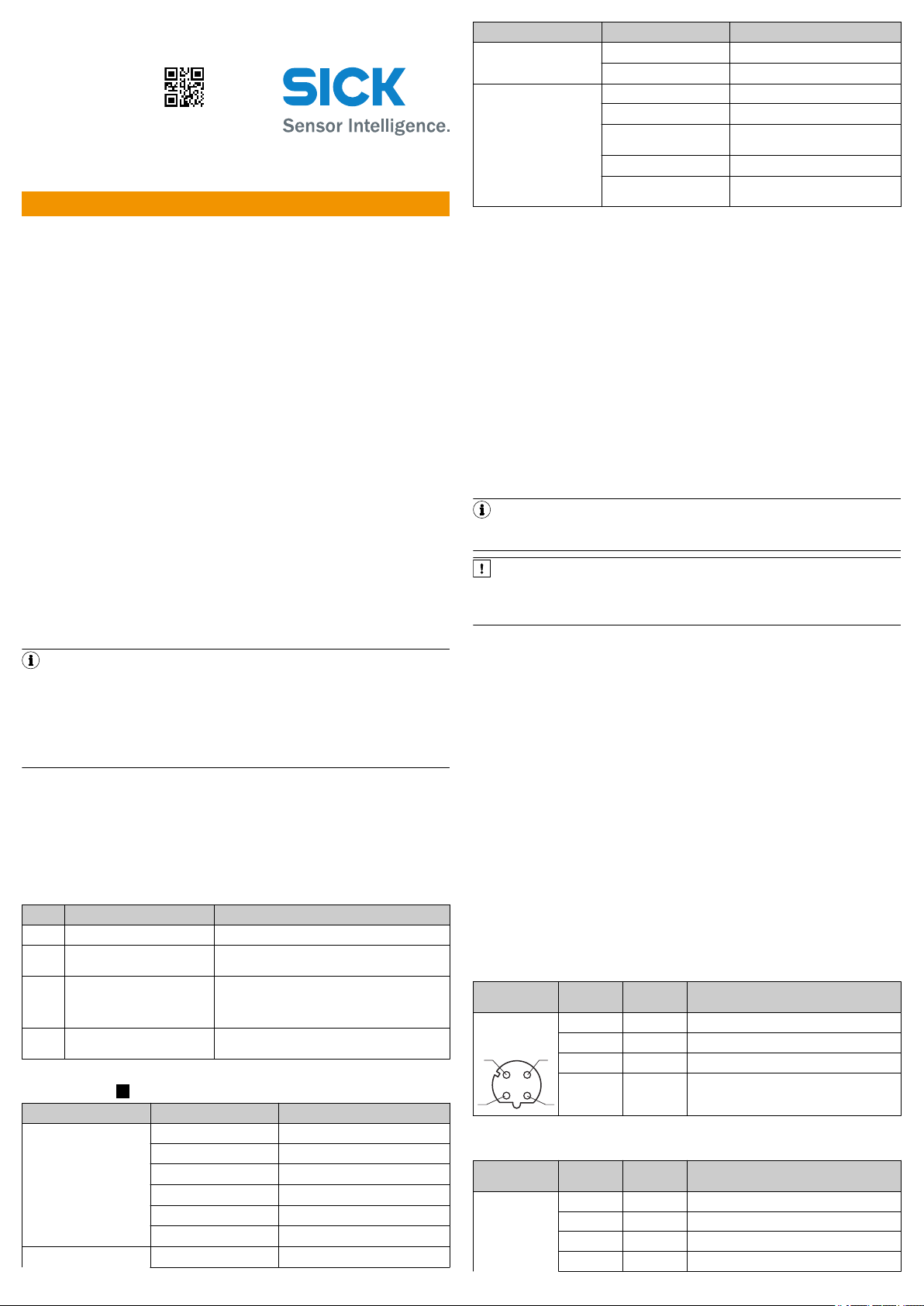
5.2 Connection diagram Ethernet
Pin assignment for Ethernet connection
Male/female
connector
M12 female
connector, 4-pin
D-coded
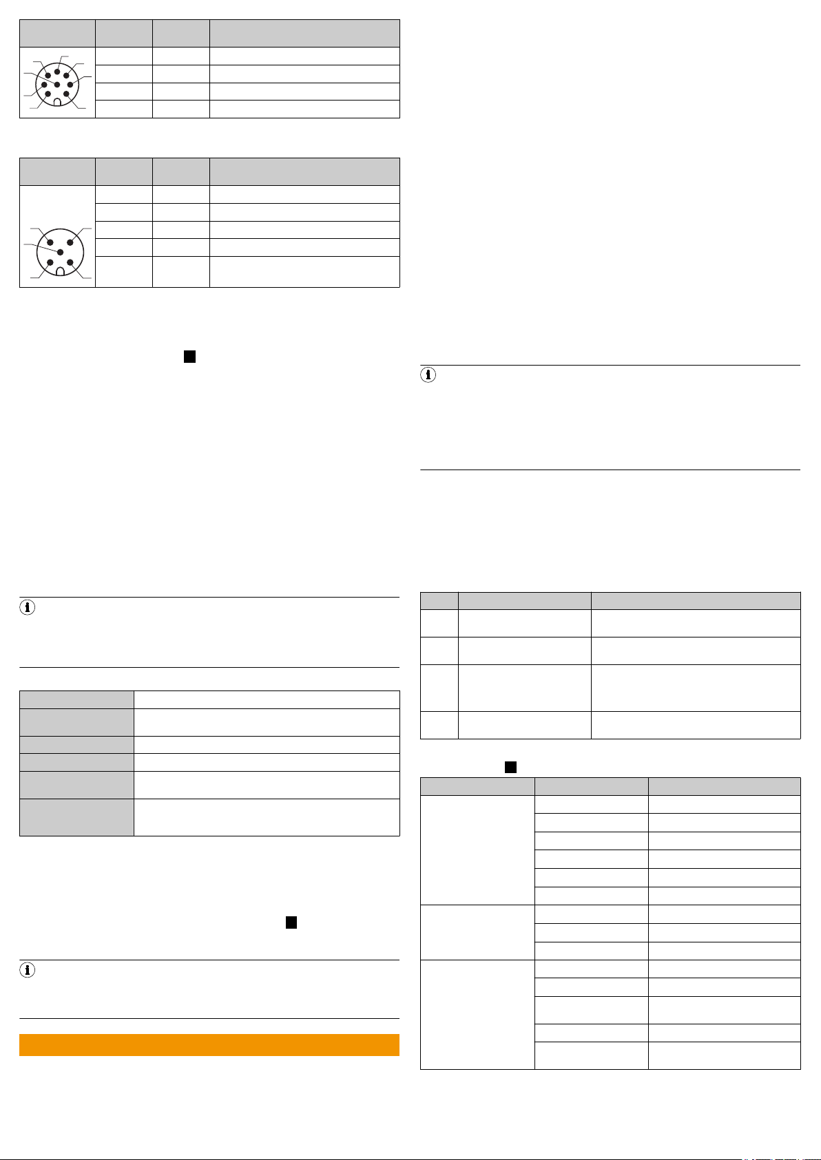
CAN
Pin assignment for CAN connection
Male/female
connector
M12 male con‐
nector, 8-pin Acoded
Pin Short form Signal description
1 TX+ Transmit data positive
2 RX+ Receive data positive
3 TX- Transmit data negative
4 RX- Receive data negative
Pin Short form Signal description
1 CAN H CAN high
2 CAN L CAN low
3 IN2 Input 2
4 GND IN1/2 Earth input 1/2
Page 2
1
7
2
6
3
4
5
8
1
4 3
5
2
•
Male/female
connector
Pin Short form Signal description
5 OUT2 Output 2
6 OUT3 Output 3
7 GND Earth
8 OUT4 Output 4
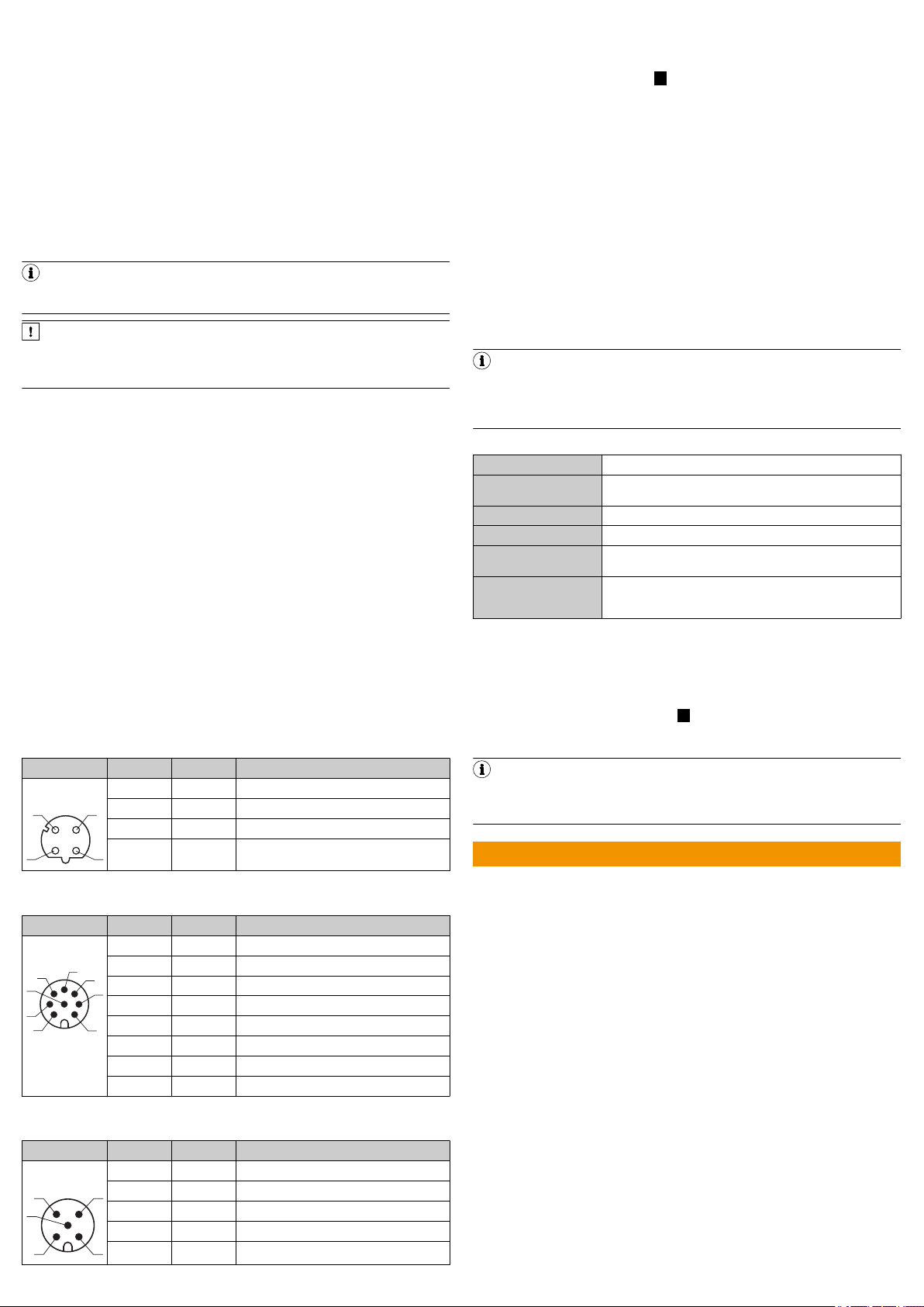
Power
Pin assignment Power connection
Male/female
connector
M12 male con‐
nector, 5-pin Acoded
Pin Short form Signal description
1 L+ Supply voltage: +9.5 … +36 V DC
2 LIN1 Input 1
3 GND Earth
4 OUT1 Output 1
5 GND IN1/2 Earth input 1/2
Safety Notes Radarsensoren (Nr. 8021532), gedruckt beiliegend
•
Betriebsanleitung RMS3xx (Deutsch: Nr. 8021529, Englisch: Nr. 8021530),
im Internet zum Download
•
Technische Information RMS3xx "Regulatorische Hinweise" (Nr. 8021596),
gedruckt beiliegend
•
Telegram Listing RMS3xx (Englisch: Nr. 8021531), im Internet zum Down‐
load
Diese Dokumente (zum Download) und weitere Informationen wie z. B. Anwen‐
dungsbeispiele und zugehörige Software finden Sie auf der SICK-Produktseite im
Internet unter: www.sick.com/RMS3xx
Alle Rechte vorbehalten. Irrtümer und Änderungen vorbehalten.
2 Zu Ihrer Sicherheit
2.1 Bestimmungsgemäße Verwendung
Der Radarsensor RMS3xx dient zur Bereichsüberwachung. Der Sensor erkennt in
einem definierten Erfassungsfeld statische und bewegte Objekte und löst bei
Erkennung eines entsprechenden Objekts ein Schaltsignal aus.
Distanz-Zonen können definiert werden und diesen Zonen verschiedene Funktio‐
nen zugewiesen werden.
Die Distanz der Objekte, die Geschwindigkeit und die Richtung der Bewegung
5.3 Connecting the device electrically
1. Ensure the voltage supply is not connected.
2. Connect the device according to the connection diagram, Connection dia‐
gram, page 1.
RMS3xx connection overview: B
3. Switch on the supply voltage.
✓ The initialization phase starts, the Power LED lights up yellow. As soon as the
Power LED lights up green, the device is ready for operation.
innerhalb des Erfassungsbereichs wird berechnet und über das Daten-Telegramm
bereitgestellt.
Alle Objektdaten können über Ethernet bereitgestellt werden, ebenso ist eine
Bereitstellung über das CAN-Protokoll möglich.
Zur Bedienung des RMS3xx muss die Software SOPAS_ET der SICK AG verwendet
werden.
HINWEIS
Der Radarsensor ist zum Betrieb in den Ländern zugelassen, die in der Tech‐
nischen Information RMS3xx "Regulatorische Hinweise" (Nr. 8021596) gelis‐
tet sind. Dieses Dokument liegt dem Gerät bei. Bei Betrieb des Geräts in
6 Operation
6.1 General advice
The device works fully automatically in normal operation and requires no operator
intervention.
6.2 Switching on / Switching off
1. Disconnect the device from the voltage supply to switch it off.
✓ The device switches off. The device configuration remains unchanged, mea‐
anderen Ländern können geschützte Frequenzbereiche gestört werden.
•
Gerät nur in Ländern betreiben für die eine Zulassung vorliegt.
•
Beim Weiterverkauf des Geräts den Käufer über die regionalen Zulas‐
sungesbeschränkungen informieren.
Die SICK AG übernimmt keine Haftung für direkte oder indirekte Verluste oder
Schäden, die aus der Benutzung des Produkts resultieren. Dies gilt insbesondere
für eine andersartige Verwendung des Produkts, die nicht mit dem beabsichtigten
Zweck übereinstimmt und die nicht in dieser Dokumentation beschrieben ist.
sured values are lost.
2. Connect the device to the voltage supply.
✓ The device starts with the last saved configuration data.
7 Technical data (excerpt)
NOTE
The relevant online data sheet for your product, including technical data,
dimensional drawing, and connection diagrams, can be downloaded, saved,
and printed from the Internet:
•
www.sick.com/RMS3xx
7.1 Features
Measurement principle FMCW
Radio equipment
approval
See “Regulatory Compliance Information” technical information
(no. 8021596) included with the product
Frequency band 24.05 GHz … 24.25 GHz
Transmitting power +12.7 EIRP(dBm)
Aperture angle ± 8° vertical
Operating range 1 m … 45 m
1
Under 1 m, only presence detection
2
Typical radar cross section value for a pedestrian
3
Typical radar cross section value for a car
± 50° horizontal
20 m typical (1 m² RCS 2)
40 m typical (10 m² RCS 3)
1
7.2 Mechanics/electronics
Dimensional drawing
Dimensional drawing RMS3xx (dimensions in mm (inch)): C
8 Accessories
NOTE
Accessories and where applicable mounting information can be found online
at:
•
www.sick.com/RMS3xx
Q U I C K S T A R T d e
1 Zu diesem Dokument
Dieser Quickstart dient dazu, das Produkt schnell und einfach in Betrieb zu neh‐
men.
Ergänzende und mitgeltende Dokumente:
8023323//2018-07-30/en, de, es, pt, ko RMS3xx | SICK 2
3 Produktbeschreibung
3.1 Lieferumfang
Die Lieferung des Geräts umfasst folgende Komponenten:
Stück Komponente Bemerkung
1 Gerät in der bestellten Ausfüh‐
rung
1 Satz Schutzkappen für elektri‐
sche Anschlüsse
1 Gedruckte Technische Informa‐
tion RMS3xx "Regulatorische
Hinweise" (Nr. 8021596)
1 Gedruckte Safety Notes, mehr‐
sprachig (Nr. 8021532)
3.2 Anzeigeelemente
Anzeigeelemente: A
LED Leuchtmuster / Farbe Beschreibung
Power - / - Gerät aus
I/O
Link - /- keine Verbindung
O = leuchtet; Ö = blinkt
Ohne Anschlussleitungen und Halterungen
Beigelegt oder ggf. angebracht
Informiert über die Länder, für die eine Zulassung
vorliegt; nennt länderspezif ische Besonderheiten,
die beim Betrieb des RMS3xx zu berücksichtigen
sind.
Informiert über die Vorausset zungen für eine
sichere Verwendung des Produkts.
O / gelb
O / grün
Ö / rot
Ö / violett
Ö / grün
O / grün
O / gelb
O / rot
O / grün
Ö / grün
O / gelb
Ö / gelb
Initialisierungsphase
Gerät betriebsbereit
Gerätefehler
Firmwareupdate läuft
Firmwareupdate abgeschlossen
keine Feldverletzung
Feldverletzung Informationsfeld
Feldverletzung Warnfeld
Ethernet-Verbindung
Datenübertragung über EthernetVerbindung
CAN-Verbindung
Datenübertragung über CAN-Verbin‐
dung
Page 3
4 Montage
1
43
2
1
7
2
6
3
4
5
8
1
4 3
5
2
4.1 Montagehinweise
•
Technische Daten einhalten.
•
Sensor vor direkten Sonnenstrahlen schützen.
•
Um Kondenswasser zu vermeiden, Sensor keinem schnellen Temperatur‐
wechsel aussetzen.
•
Der Montageort muss für das Gewicht des Geräts geeignet sein.
•
Gerät möglichst erschütterungs- und schwingungsfrei befestigen. Montage‐
zubehör ist optional erhältlich, siehe Zubehör, Seite 3.
•
Bei Montage im Außenbereich wird die Verwendung einer Wetterschutz‐
haube und eines Montagewinkels empfohlen. Informationen zu optional
erhältlichem Zubehör, Zubehör, Seite 3.
5 Elektrische Installation
5.1 Verdrahtungshinweise
HINWEIS
Vorkonfektionierte Leitungen finden Sie im Internet unter:
•
www.sick.com/RMS3xx
WICHTIG
Störungen durch unsachgemäße Verdrahtung!
Eine unsachgemäße Verdrahtung kann zu Störungen im Betrieb führen.
•
Verdrahtungshinweise genau befolgen.
•
Anschlussleitungen im spannungslosen Zustand anschließen. Versorgungs‐
spannung erst nach vollständiger Installation/Anschluss aller Anschlusslei‐
tungen an Gerät und Steuerung einschalten.
•
Die Adern unbenutzter Schaltausgänge müssen schaltschrankseitig isoliert
werden.
•
Für die Anwendung / Umgebung passende Anschlussleitungen und –Stecker
verwenden, siehe Zubehör, Seite 3.
•
Die spezifizierte Schutzart des Geräts gilt nur bei geeignetem Gegenstecker
oder Schutzkappen im montierten Zustand.
•
Elektrische Schutzklasse III / Versorgungsspannung SELV.
•
Versorgungsspannung entsprechend Angaben in den technischen Daten
auslegen.
•
Die Spannungsversorgung bzw. das Netzteil muss den SELV-Anforderungen
gemäß der aktuell gültigen EN 60950-1 entsprechen (SELV = Sicherheits‐
kleinspannung).
•
Die Spannungsversorgung über ein Netzteil muss in der Lage sein, einen
kurzen Stromausfall von 20 ms zu puffern.
•
Produktschäden durch Kurzschluss verhindern: Der Versorgungsspannungs‐
eingang des Geräts verfügt über einen Verpolschutz. Die interne Funktions‐
erde, die auch dem Minuspol der Versorgungsspannung für das Gerät ent‐
spricht, ist direkt mit dem Metallgehäuse des Geräts verbunden.
5.2 Anschlussschema
Ethernet
Pinbelegung Anschluss Ethernet
Stecker/Dose Kontakt Kurzzeichen Signalbeschreibung
M12-Dose, 4pol.
D-Kodiert
1 TX+ Transmit data positiv
2 RX+ Receive data positiv
3 TX- Transmit data negativ
4 RX- Receive data negativ
5.3 Gerät elektrisch anschließen
1. Spannungsfreiheit sicherstellen.
2. Gerät gemäß Anschlussschema anschließen, Anschlussschema, Seite 3.
Anschlussübersicht RMS3xx: B
3. Versorgungsspannung einschalten.
✓ Die Initialisierungsphase startet, die Power-LED leuchtet gelb. Sobald die
Power-LED grün leuchtet, ist das Gerät betriebsbereit.
6 Bedienung
6.1 Allgemeine Hinweise
Das Gerät arbeitet im Normalbetrieb vollautomatisch ohne Eingriff eines Bedie‐
ners.
6.2 Ausschalten / Einschalten
1. Das Gerät von der Spannungsversorgung trennen, um es auszuschalten.
✓ Das Gerät schaltet sich aus. Die Gerätekonfiguration bleibt erhalten, Mess‐
werte gehen verloren.
2. Gerät an die Spannungsversorgung anschließen.
✓ Das Gerät startet mit den zuletzt gespeicherten Konfigurationsdaten.
7 Technische Daten (Auszug)
HINWEIS
Über das Internet können Sie sich für Ihr Produkt das zugehörige OnlineDatenblatt mit technischen Daten, Maßzeichnung und Anschlussschemata
herunterladen, speichern und drucken:
•
www.sick.com/RMS3xx
7.1 Merkmale
Messprinzip FMCW
Funkzulassung Siehe Technische Information "Regulatory Compliance Informa‐
tion" (Nr. 8021596), liegt dem Produkt bei
Frequenzband 24,05 GHz … 24,25 GHz
Sendeleistung +12,7 EIRP(dBm)
Öffnungswinkel ± 8° vertikal
Arbeitsbereich 1 m … 45 m
1
Unterhalb 1 m nur Anwesenheitserkennung
2
Typischer Radarquerschnittwert für einen Fußgänger
3
Typischer Radarquerschnittwert für einen PKW
± 50° horizontal
20 m typisch (1 m² RCS 2)
40 m typisch (10 m² RCS 3)
1
7.2 Mechanik/Elektrik Maßzeichnung
Maßzeichnung RMS3xx (Maße in mm): C
8 Zubehör
HINWEIS
Zubehör und gegebenenfalls Montageinformationen finden Sie im Internet
unter:
•
www.sick.com/RMS3xx
G U Í A D E I N Í C I O R Á P I D O e s
CAN
Pinbelegung Anschluss CAN
Stecker/Dose Kontakt Kurzzeichen Signalbeschreibung
M12-Stecker,
8pol. A-Kodiert
1 CAN H Can high
2 CAN L CAN low
3 IN2 Eingang 2
4 GND IN1/2 Erde Eingang 1/2
5 OUT2 Ausgang 2
6 OUT3 Ausgang 3
7 GND Erde
8 OUT4 Ausgang 4
Power
Pinbelegung Anschluss Power
Stecker/Dose Kontakt Kurzzeichen Signalbeschreibung
M12-Stecker,
5pol. A-Kodiert
1 L+ Versorgungsspannung: +9,5 … +36 V DC
2 LIN1 Eingang 1
3 GND Erde
8023323//2018-07-30/en, de, es, pt, ko RMS3xx | SICK 3
4 OUT1 Ausgang 1
5 GND IN1/2 Erde Eingang 1/2
1 Acerca de este documento
La finalidad de esta guía de inicio rápido es permitir la puesta en servicio rápida y
sencilla del producto.
Documentación adicional y otros documentos aplicables:
•
Notas de seguridad de sensores de radar (Nº 8021532), impresas adjuntas
•
Instrucciones de uso RMS3xx (Alemán: Nº 8021529, Inglés: Nº 8021530),
en Internet para descargar
•
Información técnica RMS3xx “Indicaciones regulatorias” (Nº 8021596),
impresa adjunta
•
Telegram Listing RMS3xx (Inglés: Nº 8021531), en Internet para descargar
Encontrará estos documentos (para descargar) y otras informaciones, como p. ej.
ejemplos de aplicación y el software correspondiente, en la página del producto
SICK en Internet: www.sick.com/RMS3xx
Todos los derechos reservados. Sujeto a cambio sin previo aviso.
2 Para su seguridad
2.1 Uso conforme a lo previsto
El sensor de radar RMS3xx sirve para la supervisión de zona. El sensor detecta en
un campo de detección definido objetos estáticos y en movimiento, y activa una
señal de conmutación cuando detecta los objetos correspondientes.
Pueden definirse zonas de distancia y asignarse a las mismas diferentes funcio‐
nes.
Se calcula la distancia de los objetos, la velocidad y la dirección del movimiento
dentro del área de detección y se facilita a través del telegrama de datos.
Page 4

Todos los datos del objeto pueden facilitarse a través de Ethernet, también puede
1
43
2
1
7
2
6
3
4
5
8
1
4 3
5
2
facilitarse a través del protocolo CAN.
Para manejar el RMS3xx debe utilizarse el software SOPAS_ET de SICK AG.
INDICACIÓN
El sensor de radar está autorizado para funcionar en países listados en la
Información Técnica RMS3xx “Indicaciones Regulatorias” (Nº 8021596). Este
documento se adjunta al dispositivo. Si se utiliza el dispositivo en otros
países puede interferir con las gamas de frecuencias protegidas.
•
El dispositivo solo debe utilizarse en países para los que existe una
homologación.
•
Si se revende el dispositivo, informe al comprador sobre las limitaciones
regionales de homologación.
SICK AG no se responsabiliza de las pérdidas directas o indirectas ni de los daños
resultantes del uso del producto. Esto es aplicable en particular a un uso dife‐
rente del producto que no se corresponda con el uso previsto y que no se des‐
criba en la presente documentación.
3 Descripción del producto
3.1 Volumen de suministro
El suministro del dispositivo incluye los componentes siguientes:
Unida‐
Componente Observación
des
1 Dispositivo en la ejecución
solicitada
1 Juego de tapas protectoras
para conexiones eléctricas
1 Información técnica RMS3xx
“Indicaciones regulatorias”
(Nº 8021596) impresa
1 Notas de seguridad impresas,
múltiples idiomas
(Nº 8021532)
3.2 Indicadores
Indicadores: A
LED Patrón luminoso / color Descripción
Sin soportes ni cables de conexión
Adjunto o, si conviene, instalado
Informa sobre los países para los que existe una
homologación; indica las particularidades
específicas de los países que deben tenerse en
cuenta para el funcionamiento del RMS3xx.
Informa sobre los requisitos para un uso seguro
del producto.
IMPORTANTE
¡Interferencias debido a cableado inadecuado!
Un cableado inadecuado puede causar interferencias durante el funciona‐
miento.
•
Deben seguirse exactamente las indicaciones de cableado.
•
Conectar los cables de conexión en estado sin tensión. La tensión de ali‐
mentación debe activarse después de la instalación/conexión completa de
todos los cables de conexión al dispositivo y el controlador.
•
Los conductores de las salidas conmutadas no utilizadas deben aislarse en
el lado del armario de distribución.
•
Deben utilizarse cables de conexión y conectores macho apropiados para la
aplicación / el entorno, véase Accesorios, página 5.
•
El tipo de protección especificado del dispositivo solo es válido con el conec‐
tor macho ficha o la tapa protectora apropiado montado.
•
Clase de protección eléctrica III / Tensión de alimentación SELV.
•
Diseñar la tensión de alimentación según los datos técnicos.
•
La alimentación de tensión o la fuente de alimentación debe corresponder a
los requisitos conforme a SELV según la norma actual EN 60950-1 (SELV =
tensión de seguridad muy baja).
•
La alimentación de tensión a través de una fuente de alimentación debe
poder alimentar durante un fallo de corriente breve de 20 ms.
•
Deben evitarse los daños en el producto debido a cortocircuito: La entrada
de tensión de alimentación del dispositivo tiene una protección contra pola‐
rización inversa. La tierra de función interna, que también corresponde al
polo negativo de la tensión de alimentación del dispositivo, está conectada
directamente a la carcasa metálica del dispositivo.
5.2 Esquema de conexión Ethernet
Asignación de terminales de conexión Ethernet
Conectores
macho/hembra
Conector hem‐
bra M12, 4pol.
Con codificación
D
Contacto Abreviación Descripción de señal
1 TX+ Transmit data positiv
2 RX+ Receive data positiv
3 TX- Transmit data negativ
4 RX- Receive data negativ
Alim. - / - Dispositivo apagado
O / amarillo
O / verde
Ö / rojo
Ö / violeta
Ö / verde
E/S
O / verde
O / amarillo
O / rojo
Enlace - /- Sin conexión
O / verde
Ö / verde
O / amarillo
Ö / amarillo
O = se ilumina; Ö = parpadea
4 Montaje
4.1 Indicaciones de montaje
•
Deben cumplirse los datos técnicos.
•
Proteja el sensor contra la radiación solar directa.
•
Para evitar agua condensada, no debe exponerse el sensor a un cambio
rápido de temperatura.
•
El lugar de montaje debe poder soportar el peso del dispositivo.
•
El dispositivo debe fijarse sin sacudidas ni vibraciones en la medida de lo
posible. Accesorios de montaje obtenibles opcionalmente, véase Accesorios,
página 5.
•
Si se monta en exterior, se recomienda utilizar una cubierta de protección
contra la intemperie y una escuadra de fijación. Informaciones sobre acce‐
sorios opcionales, Accesorios, página 5.
5 Instalación eléctrica
5.1 Indicaciones de cableado
INDICACIÓN
Puede encontrar cables preconfeccionados en la página web:
•
www.sick.com/RMS3xx
8023323//2018-07-30/en, de, es, pt, ko RMS3xx | SICK 4
Fase de inicialización
Dispositivo operativo
Fallo del dispositivo
Actualización de firmware en curso
Actualización de firmware finalizada
Sin vulneración del campo
Vulneración del campo de infor‐
mación
Vulneración del campo de adver‐
tencia
Conexión Ethernet
Transmisión de datos mediante
conexión Ethernet
Conexión CAN
Transmisión de datos mediante
conexión CAN
CAN
Asignación de terminales de conexión CAN
Conectores
macho/hembra
Conector macho
M12, 8pol. Con
codificación A
Contacto Abreviación Descripción de señal
1 CAN H Can high
2 CAN L CAN low
3 IN2 Entrada 2
4 GND IN1/2 Entrada tierra 1/2
5 OUT2 Salida 2
6 OUT3 Salida 3
7 GND Tierra
8 OUT4 Salida 4
Alim.
Asignación de terminales de conexión Alim.
Conectores
macho/hembra
Conector macho
M12, 5pol. Con
codificación A
Contacto Abreviación Descripción de señal
1 L+ Tensión de alimentación: +9,5 … +36 V CC
2 LIN1 Entrada 1
3 GND Tierra
4 OUT1 Salida 1
5 GND IN1/2 Entrada tierra 1/2
5.3 Conexión eléctrica del dispositivo
1. Verificar la ausencia de tensión.
2. Conectar el dispositivo según el esquema de conexión, Esquema de
conexión, página 4.
Visión general de conexión RMS3xx: B
3. Conectar la tensión de alimentación.
✓ La fase de inicialización comienza, el LED Alim. se ilumina amarillo. En
cuanto el LED Alim. se ilumina verde, el dispositivo está operativo.
6 Manejo
6.1 Indicaciones generales
En el modo normal, el dispositivo funciona automáticamente, sin intervención del
operador.
Page 5

6.2 Desconexión / conexión
1. Desenchufar el dispositivo de la fuente de alimentación para desconectar.
✓ El dispositivo se desconecta. La configuración del dispositivo se mantiene,
los valores medidos se pierden.
2. Conectar el dispositivo a la fuente de alimentación.
✓ El dispositivo se inicia con los últimos datos de configuración guardados.
7 Datos técnicos (extracto)
INDICACIÓN
A través de Internet puede descargar, guardar e imprimir la hoja de datos
online correspondiente a su producto, que incluye datos técnicos, dimensio‐
nes y esquemas de conexión:
•
www.sick.com/RMS3xx
7.1 Características
Principio de medición FMCW
Homologación de radio Ver la información técnica “Regulatory Compliance Information”
(Nº 8021596) que se adjunta al producto
Banda de frecuencias 24,05 GHz … 24,25 GHz
Potencia de transmisión +12,7 EIRP(dBm)
Ángulo de apertura ± 8° vertical
Área de trabajo 1 m … 45 m
1
Menos de 1 m solo detección de presencia
2
Valor típico de sección transversal de radar para un peatón
3
Valor típico de sección transversal de radar para un automóvil
± 50° horizontal
20 m típico (1 m² RCS 2)
40 m típico (10 m² RCS 3)
1
7.2 Sistema mecánico y eléctrico Dibujo acotado
Dibujo acotado RMS3xx (medidas en mm): C
8 Accesorios
INDICACIÓN
Puede encontrar accesorios y, si conviene, informaciones de montaje en la
página web:
•
www.sick.com/RMS3xx
G U I A D E I N Í C I O R Á P I D O p t
1 Sobre este documento
Este guia de início rápido visa facilitar e agilizar a colocação em operação do pro‐
duto.
Outros documentos complementares e aplicáveis:
•
Safety Notes (Notas de Segurança) Sensores de radares (n.º 8021532),
impresso em anexo
•
Manual de instruções RMS3xx (Alemão: n.º 8021529, Inglês: n.º 8021530),
disponível para download na Internet
•
Informações Técnicas RMS3xx “Informações regulamentares” (n.º
8021596), impresso em anexo
•
Telegram Listing (Listagem de Telegramas) RMS3xx (Inglês: n.º 8021531),
disponível para download na Internet
Estes documentos (para download) e outras informações, como, p.ex., exemplos
de aplicação e software associado podem ser encontradas na página de produ‐
tos da SICK na internet, em: www.sick.com/RMS3xx
Todos os direitos reservados. Sujeito a alterações sem aviso prévio.
2 Para a sua segurança
2.1 Utilização correta
O sensor de radares RMS3xx é usado para monitoramento de áreas. O sensor
detecta, num campo de detecção definido, objetos estáticos e móveis e aciona
um sinal de comutação no caso de detecção de um respectivo objeto.
As zonas de distância podem ser definidas e podem ser atribuídas diferentes
funções a estas zonas.
A distância dos objetos, a velocidade e a direção do movimento dentro da área de
detecção são calculados e disponibilizados através do telegrama de dados.
Todos os dados do objeto podem ser disponibilizados via Ethernet, sendo
também possível uma disponibilização através do protocolo CAN.
O software SOPAS_ET da SICK AG deve ser usado para operar o RMS3xx.
NOTA
O sensor de radares está aprovado para operação nos países listados nas
Informações Técnicas RMS3xx “Informações regulamentares” (n.º 8021596).
Este documento está anexado ao dispositivo. Operar o dispositivo em outros
países pode interferir nas gamas de frequência protegidas.
•
Operar o dispositivo somente em países onde existe uma licença para
isso.
•
Ao vender o dispositivo a terceiros, informar o comprador sobre as res‐
trições regionais da licença.
A SICK AG se isenta de qualquer responsabilidade por perdas ou danos ou per‐
das resultantes da utilização do produto. Isto é especialmente válido para uma
utilização do produto que seja diferente da finalidade prevista e que não esteja
descrita nesta documentação.
3 Descrição do produto
3.1 Material fornecido
O fornecimento do dispositivo abrange os seguintes componentes:
Uni‐
Componente Observação
dade
1 Dispositivo no modelo enco‐
mendado
1 Conjunto de tampas de
proteção para ligações elétri‐
cas
1 Informações Técnicas RMS3xx
“Informações regulamentares”
(n.º 8021596) impressas
1 Safety Notes (Notas de Segu‐
rança), vários idiomas
(n.º 8021532) impresso
Sem cabos de conexão e suportes
Incluído ou anexado, se necessário
Informa sobre os países, para os quais está dis‐
ponível uma licença; indica características
específicas do país que devem ser tidas em consi‐
deração ao operar o RMS3xx.
Informa sobre os pré-requisitos para uma uti‐
lização segura do produto.
3.2 Elementos de sinalização
Elementos de sinalização: A
LED Esquema de
iluminação/cor
Descrição
Power - / - Dispositivo desligado
Fase de inicialização
Dispositivo operacional
Erro do dispositivo
Atualização de firmware em
execução
Atualização de firmware concluída
sem violação de campo
Campo de informação de violação
de campo
Campo de aviso de violação de
campo
I/O
O/amarelo
O/verde
Ö/vermelho
Ö/violeta
Ö/verde
O/verde
O/amarelo
O/vermelho
Link - /- sem ligação
O/verde
Ö/verde
O/amarelo
Ö/amarelo
O = aceso; Ö = intermitente
Ligação Ethernet
Transmissão de dados via ligação
Ethernet
Ligação CAN
Transmissão de dados via ligação
CAN
4 Montagem
4.1 Orientações para montagem
•
Cumprir dados técnicos.
•
Proteger o sensor da luz solar direta.
•
Para evitar a água condensada, não expor o sensor a mudanças rápidas de
temperatura.
•
O local de montagem deve ser adequado ao peso do dispositivo.
•
Fixar o dispositivo tão livre de vibrações e oscilações quanto possível. Estão
disponíveis acessórios de montagem, opcionalmente, ver Acessórios,
página 6.
•
Ao montar numa área exterior, recomenda-se a utilização de uma capa pro‐
tetora contra intempéries e um ângulo de montagem. Informações sobre os
acessórios disponíveis opcionalmente, Acessórios, página 6.
5 Instalação elétrica
5.1 Indicações para cabeamento
NOTA
Encontrará cabos pré-montados na Internet, em:
•
www.sick.com/RMS3xx
IMPORTANTE
Avarias devido a cablagem incorreta!
Uma cablagem incorreta pode levar a avarias na operação.
•
Seguir as instruções para cablagem de forma precisa.
•
Ligar os cabos de conexão no status desenergizado. Ligar a tensão de ali‐
mentação somente após a instalação/conexão completa de todos os cabos
de conexão ao dispositivo e ao controle.
•
Os fios das saídas de comutação não utilizadas devem estar isolados no
lado do armário de distribuição.
8023323//2018-07-30/en, de, es, pt, ko RMS3xx | SICK 5
Page 6

•
1
43
2
1
7
2
6
3
4
5
8
1
4 3
5
2
Utilizar cabos de conexão e conectores apropriados à aplicação/ao ambi‐
ente, ver Acessórios, página 6.
•
O grau de proteção especificado do dispositivo só se aplica com o conector
oposto adequado ou as tampas de proteção no status montado.
•
Classe de proteção elétrica III/tensão de alimentação SELV.
•
Ajustar a tensão de alimentação de acordo com as especificações nos
dados técnicos.
•
A alimentação de tensão ou a fonte de alimentação deve atender os requisi‐
tos SELV de acordo com a norma EN 60950-1 em vigor (SELV = Safety Extra
Low Voltage - tensão de segurança extrabaixa).
•
A alimentação de tensão, por meio de uma fonte de alimentação, deve ser
capaz de amortecer uma falha de energia curta de 20 ms.
•
Evitar danos ao produto devido a curto-circuito: A entrada de tensão de ali‐
mentação do dispositivo possui uma proteção contra inversão de polari‐
dade. A ligação à terra funcional interna, que também corresponde ao polo
negativo da tensão de alimentação do dispositivo, é conectada diretamente
à estrutura de metal do dispositivo.
5.2 Esquema de conexões Ethernet
Ocupação de pinos conexão Ethernet
Conector
macho/conec‐
tor fêmea
Conector macho
M12, 4pinos
Codificação D
Contato Símbolo Descrição do sinal
1 TX+ Transmitir dados positivos
2 RX+ Receber dados positivos
3 TX- Transmitir dados negativos
4 RX- Receber dados negativos
7 Dados técnicos (resumo)
NOTA
Você pode baixar, salvar e imprimir a data Sheet online associada com dados
técnicos, desenho dimensional e esquema de conexões para o seu produto
através da Internet:
•
www.sick.com/RMS3xx
7.1 Características
Princípio de medição FMCW (Frequency-Modulated Continuous Wave - Onda Contínua
Autorização de uso de
radiofrequência
Modulada por Frequência)
Ver Informação Técnica “Regulatory Compliance Information”
(nº 8021596), anexada ao produto
Faixa de frequência 24,05 GHz … 24,25 GHz
Potência de transmissão +12,7 EIRP(dBm)
Ângulo de abertura ± 8° vertical
Área de trabalho 1 m … 45 m
1
Abaixo de 1 m apenas detecção de presença
2
Valor típico da seção transversal do radar para um pedestre
3
Valor típico da seção transversal do radar para um veículo ligeiro
± 50° horizontal
20 m típico (1 m² RCS 2)
40 m típico (10 m² RCS 3)
1
7.2 Mecânica/sistema elétrico
Desenho dimensional
Desenho dimensional RMS3xx (dimensões em mm): C
8 Acessórios
NOTA
CAN
Ocupação de pinos conexão CAN
Conector
macho/conec‐
tor fêmea
Conector macho
M12, 8pinos
Codificado A
Contato Símbolo Descrição do sinal
1 CAN H CAN high
2 CAN L CAN low
3 IN2 Entrada 2
4 GND IN1/2 Entrada terra 1/2
5 OUT2 Saída 2
6 OUT3 Saída 3
7 GND Terra
8 OUT4 Saída 4
Power
Ocupação de pinos conexão Power
Conector
macho/conec‐
tor fêmea
Conector macho
M12, 5pinos
Codificado A
Contato Símbolo Descrição do sinal
1 L+ Tensão de alimentação: +9,5 … +36 V CC
2 LIN1 Entrada 1
3 GND Terra
4 OUT1 Saída 1
5 GND IN1/2 Entrada terra 1/2
Pode se encontrar acessórios e, eventualmente, informações de montagem
na Internet, em:
•
www.sick.com/RMS3xx
퀵 스 타 트 k o
1 본 문서에 관하여
이 퀵 스타트의 목적은 제품을 쉽고 빠르게 작동하게 함에 있습니다.
보완 및 추가 문서:
레이더 센서 안전지침(No. 8021532), 인쇄물로 첨부
•
작동 지침서 RMS3xx(독일어: No. 8021529, 영어: No. 8021530), 인터넷에
•
서 다운로드
기술정보 RMS3xx “규제 지침”(No. 8021596), 인쇄물로 첨부
•
텔레그램 리스트 RMS3xx(영어: No. 8021531), 인터넷에서 다운로드
•
본 문서들(다운로드용)과 예를 들어 사용사례, 관련 소프트웨어 등과 같은 기타
정보들은 다음 인터넷 주소의 SICK 제품 페이지에서 확인할 수 있습니다.
www.sick.com/RMS3xx
All rights reserved 예고 없이 변경 가능
2 안전 수칙
2.1 규정에 맞는 사용
레이더 센서 RMS3xx는 구역 감시에 이용됩니다. 이 센서는 정의된 감지 필드에
서 고정 또는 유동 물체를 식별하고, 해당 물체를 식별하면 신호를 내보냅니다.
거리 구역을 정의하고 이 구역에 다양한 기능을 지정할 수 있습니다.
감지 범위 내 물체의 거리, 속도 및 움직임이 계산되고 데이터 텔레그램을 통해
제공됩니다.
물체에 대한 모든 데이터는 Ethernet이나 CAN-프로토콜을 통해서도 제공이 가
능합니다.
5.3 Ligar o dispositivo à eletricidade
1. Garantir que não há tensão.
2. Conectar o dispositivo de acordo com o esquema de conexões, Esquema de
conexões, página 6.
Vista geral das ligações RMS3xx: B
3. Ligar a tensão de alimentação.
✓ A fase de inicialização começa, o LED Power acende a amarelo. Assim que o
LED Power acender a verde, o dispositivo esta operacional.
6 Operação
6.1 Observações gerais
O dispositivo opera de forma totalmente automática na operação normal, sem a
intervenção de um operador.
6.2 Ligar/desligar
1. Desconectar o dispositivo da alimentação de tensão para o desligar.
✓ O dispositivo desliga-se. A configuração do dispositivo é mantida, os valores
medidos perdem-se.
2. Conectar o dispositivo da alimentação de tensão.
✓ O dispositivo começa com os últimos dados de configuração salvos.
8023323//2018-07-30/en, de, es, pt, ko RMS3xx | SICK 6
RMS3xx의 작동을 위해서는 SICK AG의 소프트웨어 SOPAS ET를 사용해야 합니
다.
주
레이더 센서는 기술정보 RMS3xx “규제 지침” (No. 8021596)에 나열된 국가
들에서 작동이 승인되었습니다. 본 문서는 장치에 동봉되어 있습니다. 다른
국가에서 장치를 작동할 경우 보호 주파수가 방해를 받을 수 있습니다.
승인된 국가에서만 장치를 사용하십시오.
•
장치를 재판매하는 경우 구매자에게 사용 허가 제한에 대해 알려주십
•
시오.
SICK AG는 제품의 사용으로 인한 직간접적 손실 및 손해에 대해 책임을 지지 않
습니다. 특히 제품의 본래 목적에서 벗어나며 본 문서에 기술되지 않은 사용 방
법이 이에 해당됩니다.
3 제품 설명
3.1 공급 범위
장치는 다음과 같은 내용물로 구성되어 있습니다:
개수 구성품 비고
1 주문한 사양의 장치 연결 케이블 및 브래킷 미포함
1 전기 연결부 보호용 캡 동봉 혹은 필요시 부착된 상태로
Page 7

개수 구성품 비고
1
43
2
1
7
2
6
3
4
5
8
1
4 3
5
2
1 기술정보 RMS3xx “규제 지
침” (No. 8021596) 인쇄물
1 다국어 안전 지침
(No. 8021532) 인쇄물
승인된 국가들에 대한 정보 및 RMS3xx 작동
시 주의해야 할 국가별 특이사항에 대한 안
내.
제품의 안전한 사용을 위해 필요한 요건에
대한 정보.
3.2 표시부 요소
표시부 요소: A
LED 점등방식/색상 설명
전원 - / - 장치 꺼짐
O / 노란색
O / 초록색
Ö / 빨간색
Ö / 보라색
Ö / 초록색
I/O
O / 초록색
O / 노란색
O / 빨간색
링크 - / - 연결되지 않음
O / 초록색
Ö / 초록색
O / 노란색
Ö / 노란색
O = 켜짐; Ö = 깜빡임
초기화 단계
장치 사용가능
장치 결함
펌웨어 업데이트 중
펌웨어 업데이트 완료
필드 침범 없음
정보 필드 침범
경고 필드 침범
Ethernet 연결
Ethernet 연결을 통한 데이터 전
송
CAN 연결
CAN 연결을 통한 데이터 전송
수 커넥터/암
커넥터
접촉부 약어 신호 설명
3 TX- 데이터 역방향 송신
4 RX- 데이터 역방향 수신
CAN
CAN
연결부 핀 배치
수 커넥터/암
커넥터
M12 수 커넥
터, 8핀 A 코드
접촉부 약어 신호 설명
1 CAN H Can high
2 CAN L CAN low
3 IN2 입력부 2
4 GND IN1/2 접지 입력부 1/2
5 OUT2 출력부 2
6 OUT3 출력부 3
7 GND 접지
8 OUT4 출력부 4
전원
전원 연결부 핀 배치
수 커넥터/암
커넥터
M12 수 커넥
터, 5핀 A 코드
접촉부 약어 신호 설명
1 L+ 공급 전압: +9.5 … +36V DC
2 LIN1 입력부 1
3 GND 접지
4 OUT1 출력부 1
5 GND IN1/2 접지 입력부 1/2
4 장착
4.1 마운팅 지침
장치 제원을 숙지하십시오.
•
센서를 직사광선으로부터 보호하십시오.
•
결로 현상을 피하기 위해 급격한 온도 변화에 센서를 노출시키지 마십시
•
오.
마운팅 장소는 장치의 무게에 적합해야 합니다.
•
흔들리거나 움직이지 않도록 장치를 최대한 고정하십시오. 마운팅 관련 부
•
속품은 옵션으로 제공됩니다. 참조 부속품, 페이지 8
실외 마운팅의 경우 내후성 후드와 고정 브래킷 사용을 권장합니다. 옵션
•
액세서리에 대한 정보. 부속품, 페이지 8
5 전기 설치
5.1 배선 지침
주
사전 조립된 케이블에 대해 다음 인터넷 페이지를 참조하십시오.
www.sick.com/RMS3xx
•
중요
부적절한 배선에 의한 장애!
부적절한 배선은 작동에 장애를 일으킬 수 있습니다.
•
배선 지침을 정확히 따르십시오.
연결 케이블들을 전기가 흐르지 않는 상태에서 연결합니다. 공급 전압은
•
장치와 컨트롤 시스템의 모든 케이블이 전부 설치/연결된 후에 공급합니
다.
이용하지 않는 출력 신호 스위칭 장치의 와이어는 제어함 측면에서 절연해
•
야 합니다.
용도/환경에 적합한 연결 케이블과 수 커넥터를 이용하십시오. 참조 부속
•
품, 페이지 8
장치에 지정된 보호 등급은 적합한 반대편 수 커넥터나 보호 캡이 장착된
•
상태에서만 유효합니다.
전기 보호 등급 III / 공급 전압 SELV.
•
공급 전압을 제원에 안내된 사양에 맞게 연결하십시오.
•
전압 공급 장치 및 전원 어댑터는 현행 EN 60950-1에 따른 SELV 요건에 부
•
합해야 합니다(SELV = 안전초저전압).
전원 어댑터가 있는 전압 공급 장치는 20ms의 짧은 정전을 버퍼링 할 수
•
있어야 합니다.
단락에 의한 제품 손상을 피하기 위해 장치의 공급 전압 입력부에 역 극성
•
보호 기능이 있습니다. 장치 공급 전압의 음극이기도 한 내부 기능접지는
장치의 금속 하우징에 직접 연결되어 있습니다.
5.2 결선도 Ethernet
Ethernet
연결부 핀 배치
수 커넥터/암
커넥터
M12 암 커넥
터, 4핀 D 코드
8023323//2018-07-30/en, de, es, pt, ko RMS3xx | SICK 7
접촉부 약어 신호 설명
1 TX+ 데이터 정방향 송신
2 RX+ 데이터 정방향 수신
5.3 장치 전기 연결
1. 전원이 차단되었는지 확인하십시오.
2. 결선도에 따라 장치를 연결하십시오. 결선도, 페이지 7
RMS3xx 연결 개요: B
3. 공급 전압을 공급합니다.
✓ 초기화 단계가 시작되며, 전원 LED에 노란색 불이 들어옵니다. 전원 LED가
녹색이 되면 이제 장치를 사용할 수 있습니다.
6 조작
6.1 일반 지침
일반적으로 장치는 작동자의 개입 없이 완전히 자동적으로 작동합니다.
6.2 끄기/켜기
1. 장치를 끄기 위해 전압 공급 장치에서 장치를 분리하십시오.
✓ 장치가 꺼집니다. 장치 설정은 유지되며, 측정값은 손실됩니다.
2. 장치를 전압 공급 장치에 연결하십시오.
✓ 최근 저장한 설정 데이터와 함께 장치가 켜집니다.
7 제원(발췌)
주
인터넷에서 제품의 제원, 치수 도면 및 결선도가 포함된 온라인 데이터시트
를 다운로드, 저장 및 인쇄할 수 있습니다.
www.sick.com/RMS3xx
•
7.1 특징
측정 원리 FMCW
무선 통신 인가 제품에 동봉된 기술 정보 “Regulatory Compliance
주파수 대역 24.05GHz … 24.25GHz
송출력 +12.7 EIRP(dBm)
구경각 세로 ± 8°
작동 구역 1m … 45m
1
1m 이하에선 존재만 감지
2
보행자에 대한 일반적인 레이더 횡단면 값
3
자동차에 대한 일반적인 레이더 횡단면 값
7.2 기계/전기 치수 도면
RMS3xx 치수 도면(단위 mm): C
Information” (No. 8021596) 참조
가로 ± 50°
일반적으로 20m (1m² RCS 2)
일반적으로 40m (10m² RCS 3)
1
Page 8

8 부속품
3
2
1
3
2
1
Link
I/O
Power
26 (1.0)
52 (2.0)
85 (3.3)
95 (3.7)
17.2
(0.7)
60.8 (2.4)
27.5
(1.1)
12.5
(0.5)
30
(1.2)
97 (3.8)
주
부속품과 필요시 마운팅 정보는 다음 인터넷 페이지에서 확인할 수 있습니
다.
www.sick.com/RMS3xx
•
A
B
C
8023323//2018-07-30/en, de, es, pt, ko RMS3xx | SICK 8
 Loading...