

SICK RFU62 Series, RFU620-101 Series, RFU63x-041 Series, RFU620-104 Series, RFU65x-101 Series Operating Instructions Manual
...Page 1

RFU62x
Для заказов : +7(499)707-11-20 Email: i@sp-t.ru
8-800-511-65-88 (Бесплатно по РФ)
RFID read/write device (UHF)
O P E R A T I N G I N S T R U C T I O N S
Page 2

Described product
RFU62x-101xx
RFU62x-104xx
RFU62x-105xx
Manufacturer
SICK AG
Erwin-Sick-Str. 1
79183 Waldkirch
Germany
Legal information
This work is protected by copyright. Any rights derived from the copyright shall be
reserved for SICK AG. Reproduction of this document or parts of this document is only
permissible within the limits of the legal determination of Copyright Law. Any modifica‐
tion, abridgment or translation of this document is prohibited without the express writ‐
ten permission of SICK AG.
The trademarks stated in this document are the property of their respective owner.
© SICK AG. All rights reserved.
Original document
This document is an original document of SICK AG.
Conformities
Due to the country-specific approvals for the device, the respective conformance infor‐
mation is type-dependent. For conformance information on the specific device that you
have (type description on the type label), see the online type-specific data sheet at:
www.sick.com/RFU62x
•
2
O PE R AT I NG IN S TR U CT I ON S | RFU62x 8015930/ZTM0/2018-11-06 | SICK
Subject to change without notice
Page 3

Contents
CONTENTS
1 About this document........................................................................ 6
1.1 Information on the operating instructions.............................................. 6
1.2 Scope......................................................................................................... 6
1.3 Explanation of symbols............................................................................ 7
1.4 Further information................................................................................... 8
1.5 SICK service.............................................................................................. 8
2 Safety information............................................................................ 9
2.1 Intended use............................................................................................. 9
2.2 Improper use............................................................................................. 10
2.3 Internet protocol (IP) technology.............................................................. 10
2.4 Limitation of liability................................................................................. 10
2.5 Modifications and conversions................................................................ 11
2.6 Requirements for skilled persons and operating personnel.................. 12
2.7 Operational safety and particular hazards.............................................. 13
2.8 Repairs...................................................................................................... 14
3 Product description........................................................................... 15
3.1 Product ID.................................................................................................. 15
3.2 Product characteristics............................................................................ 18
4 Transport and storage....................................................................... 25
4.1 Transport................................................................................................... 25
4.2 Unpacking.................................................................................................. 25
4.3 Transport inspection................................................................................. 25
4.4 Storage...................................................................................................... 25
5 Mounting............................................................................................. 27
5.1 Overview of mounting procedure............................................................. 27
5.2 Preparation for mounting......................................................................... 27
5.3 Mounting location..................................................................................... 31
5.4 Mounting the device................................................................................. 31
5.5 Mounting external components............................................................... 33
6 Electrical installation........................................................................ 34
6.1 Safety......................................................................................................... 34
6.2 Wiring instructions.................................................................................... 38
6.3 Overview of all interfaces and connection options................................ 38
6.4 Pin assignments of electrical connections............................................. 47
6.5 Instructions for electrical installation when the ambient temperature
can fall below 0 °C...................................................................................
6.6 Installation steps...................................................................................... 51
6.7 Connecting the supply voltage................................................................. 55
6.8 Wiring data interfaces.............................................................................. 58
6.9 Wiring the CAN interface.......................................................................... 60
49
8015930/ZTM0/2018-11-06 | SICK OP E RA T IN G I N ST R UC T IO N S | RFU62x
Subject to change without notice
3
Page 4

CONTENTS
6.10 Wiring the digital switching inputs (RFU62x-101xx/RFU62x-104xx)..... 61
6.11 Wiring the digital switching outputs (RFU62x-101xx/RFU62x-104xx).. 63
7 Commissioning.................................................................................. 66
7.1 Overview of the Commissioning Steps.................................................... 66
7.2 SOPAS ET configuration software............................................................ 66
7.3 Starting the SOPAS ET configuration software and connecting it to
the device..................................................................................................
7.4 Initial commissioning................................................................................ 68
67
8 Operation............................................................................................ 71
8.1 Operating and status indicators.............................................................. 71
9 Maintenance...................................................................................... 76
9.1 Maintenance............................................................................................. 76
9.2 Cleaning..................................................................................................... 76
10 Troubleshooting................................................................................. 77
10.1 Overview of Potential Errors and Faults.................................................. 77
10.2 Detailed fault analysis.............................................................................. 77
10.3 Status log.................................................................................................. 78
10.4 SICK service.............................................................................................. 78
10.5 Repairs...................................................................................................... 78
10.6 Returns...................................................................................................... 78
10.7 Replacing the device................................................................................ 79
11 Decommissioning............................................................................. 81
11.1 Disposal..................................................................................................... 81
12 Technical data.................................................................................... 82
12.1 Features.................................................................................................... 82
12.2 Interfaces.................................................................................................. 83
12.3 Mechanics and electronics...................................................................... 84
12.4 Ambient data............................................................................................. 85
12.5 Working range diagram............................................................................ 85
12.6 Dimensional drawing................................................................................ 86
13 Accessories........................................................................................ 87
14 Annex.................................................................................................. 88
14.1 EU declaration of conformity / Certificates............................................. 88
14.2 Certification according to UL61010-1..................................................... 88
14.3 Dimensional drawings (electronic).......................................................... 88
14.4 Signal assignment of cables with open cable end at one end.............. 88
14.5 Connection diagrams of connection module CDB620.......................... 94
14.6 Connection diagrams of connection module CDB650-204.................. 106
14.7 Connection diagrams of connection module CDM420-0001............... 119
14.8 Connection diagrams of connection module CDM420-0006............... 132
4
O PE R AT I NG IN S TR U CT I ON S | RFU62x 8015930/ZTM0/2018-11-06 | SICK
Subject to change without notice
Page 5

CONTENTS
14.9 Copyright notices...................................................................................... 146
14.10 Abbreviations used................................................................................... 146
8015930/ZTM0/2018-11-06 | SICK OP E RA T IN G I N ST R UC T IO N S | RFU62x
Subject to change without notice
5
Page 6

ABOUT THIS DOCUMENT
1
1 About this document
1.1 Information on the operating instructions
These operating instructions provide important information on how to use devices from
SICK AG.
Prerequisites for safe work are:
Compliance with all safety notes and handling instructions supplied.
•
Compliance with local work safety regulations and general safety regulations for
•
device applications
The operating instructions are intended to be used by qualified personnel and electrical
specialists.
NOTE
Read these operating instructions carefully to familiarize yourself with the device and its
functions before commencing any work.
The instructions constitute an integral part of the product and are to be stored in the
immediate vicinity of the device so they remain accessible to staff at all times. Should
the device be passed on to a third party, these operating instructions should be handed
over with it.
1.2 Scope
These operating instructions do not provide information on operating the machine or
system in which the device is integrated. For information about this, refer to the operat‐
ing instructions of the specific machine.
These operating instructions serve to incorporate the device into a customer system.
These operating instructions form part of the documentation provided to users. The
operating instructions supplement the Quick Start Guide with more detailed and addi‐
tional information. A printed copy of the Quick Start Guide for initial commissioning is
included with the device and can, if required, be downloaded online at:
www.sick.com/RFU62x
•
The following topics are covered in more detail, or only described in the operating
instructions:
Type code
•
Product features and functions (overview)
•
Measures and requirements for mounting and electrical installation of the device
•
if the device is operated at ambient temperatures below 0 °C
Measures to suppress ground potential equalization currents in applications with
•
widely distributed systems
Overview of all interfaces and connection options for the RFU62x-104xx (serial
•
variant) and RFU62x-101xx (Ethernet variant)
Wiring the individual interfaces of the device
•
Electrical wiring plans for the CDB620, CDB650-204, CDM420-0001 and
•
CDM420-0006 connection modules when used in conjunction with an RFU62x
device
Function of the additional status indicators
•
Overview of operating options and available configuration tools
•
Measures for eliminating interference
•
Instructions are given in stages for all actions required.
These instructions apply to all available device variants of the product. Functions spe‐
cific to special devices are, where necessary, described in additional documents.
6
O PE R AT I NG IN S TR U CT I ON S | RFU62x 8015930/ZTM0/2018-11-06 | SICK
Subject to change without notice
Page 7

More detailed information for identification of the available device type see "Type code",
page 15.
NOTE
The device approval was granted for a specific region. The region assignment cannot be
changed. The device must not be operated in a different region! Should the device be
passed on to a third party, these operating instructions and the Quick Start Guide
should be handed over with it.
The available device variants, and information about the radio equipment approvals are
listed on the online product page:
www.sick.com/RFU62x
•
Commissioning is described using one particular device variant as an example and
based on a default configuration of the device parameters. With the exception of the
electrical connection, other variants are commissioned in the same way. The example is
based on a simple application of detecting (reading) a transponder on an object.
1.3 Explanation of symbols
ABOUT THIS DOCUMENT 1
Warnings and important information in this document are labeled with symbols. The
warnings are introduced by signal words that indicate the extent of the danger. These
warnings must be observed at all times and care must be taken to avoid accidents, per‐
sonal injury, and material damage.
DANGER
… indicates a situation of imminent danger, which will lead to a fatality or serious
injuries if not prevented.
WARNING
… indicates a potentially dangerous situation, which may lead to a fatality or serious
injuries if not prevented.
CAUTION
… indicates a potentially dangerous situation, which may lead to minor/slight injuries if
not prevented.
NOTICE
… indicates a potentially harmful situation, which may lead to material damage if not
prevented.
NOTE
… highlights useful tips and recommendations as well as information for efficient and
trouble-free operation.
8015930/ZTM0/2018-11-06 | SICK OP E RA T IN G I N ST R UC T IO N S | RFU62x
Subject to change without notice
7
Page 8

1 ABOUT THIS DOCUMENT
1.4 Further information
NOTE
Further documentation for the device can be found on the online product page at:
www.sick.com/RFU62x
•
The following information is available for download there:
Model-specific online data sheets for device variants, containing technical data,
•
dimensional drawing, and specification diagrams
EU declaration of conformity for the product family
•
Certificates of the product family
•
Dimensional drawings and 3D CAD dimension models in various electronic for‐
•
mats
These operating instructions, available in English and German, and in other lan‐
•
guages if necessary
RFU parameter description available in English and German, and in other lan‐
•
guages if necessary
Other publications related to the devices described here
•
Publications dealing with accessories
•
1.5 SICK service
NOTE
In addition to the existing operating instructions, the use of the RFU parameter descrip‐
tion is recommended. This document explains the UHF-RFID-specific parameters of all
device variants of the RFU6xx product family at the "Service” user level.
The parameter description supports the user in configuring applications with the
SOPAS ET configuration software.
If you require any technical information, our SICK Service will be happy to help. To find
your agency, see the final page of this document.
NOTE
Before calling, make a note of all type label data such as type code, serial number, etc.,
to ensure faster processing.
8
O PE R AT I NG IN S TR U CT I ON S | RFU62x 8015930/ZTM0/2018-11-06 | SICK
Subject to change without notice
Page 9
2 Safety information
2.1 Intended use
The RFU62x RFID read/write device is an intelligent 4Dpro sensor from the SICK
RFU6xx (UHF) product family. Version (working range): Mid Range.
The device is used for the automated, fixed identification of wireless-based data cards
(transponders) on moving or stationary objects, and for the management of these data
cards. The RFU620 base model processes all standard passive transponders in accor‐
dance with EPCglobal UHF C1G2 and ISO/IEC 18000-6C in the regional UHF carrier fre‐
quency range.
Thanks to its intelligent process logic, the device can be used either as a stand-alone
solution or as part of a group in a CAN network. In read mode, the device transmits the
results via a host interface to a higher-level computer (e.g. PLC) for further centralized
processing.
The compact device includes an internal antenna that is integrated into the housing.
The various device variants offer different connection options and data interfaces.
The device can be operated within a wide ambient temperature range. For details, see
"Technical data", page 82
SAFETY INFORMATION 2
The device is primarily designed for use in industrial and logistics areas, and meets the
requirements for industrial ruggedness, interfaces and data processing. The device
can, if necessary, be programmed to implement customer-specific modifications.
NOTE
The USB interface of the device is used in industrial environments only as a service
interface for temporary use (e.g. for configuration, troubleshooting). Permanent use in
real operation of the system as a host interface is not intended.
SICK AG assumes no liability for losses or damage arising from the use of the product,
either directly or indirectly. This applies in particular to use of the product that does not
conform to its intended purpose and is not described in this documentation.
2.1.1 Operational restrictions
NOTICE
Operational restrictions!
The frequency band of the device is configured for the specific type and region when
delivered. This enables the device to be operated in the respective approved region
without interfering with protected frequencies (such as mobile communications).
Operating the device in other regions, however, can interfere with protected frequen‐
cies.
■
Only use the device in the region for which it has been approved.
■
When reselling the device, inform the buyer of the fixed region assignment.
■
For further country-specific operating requirements, see the Quick Start Guide, a
printed copy of which is enclosed with the device or can be downloaded online
(PDF) at:
°
www.sick.com/RFU62x
8015930/ZTM0/2018-11-06 | SICK OP E RA T IN G I N ST R UC T IO N S | RFU62x
Subject to change without notice
9
Page 10
2 SAFETY INFORMATION
2.1.2 Regulatory notes
Europe: simplified EU declaration of conformity
SICK AG hereby declares that the RFU62x-101xx radio equipment complies with the
2014/53/EU directive. The complete text of the EU declaration of conformity is avail‐
able at the following web address:
•
2.2 Improper use
Any use outside of the stated areas, in particular use outside of the technical specifica‐
tions and the requirements for intended use, will be deemed to be incorrect use.
•
•
•
WARNING
Danger due to improper use!
Any improper use can result in dangerous situations.
Therefore, observe the following information:
■
■
www.sick.com/RFU62x
The device does not constitute a safety component in accordance with the respec‐
tive applicable safety standards for machines.
The device must not be used in explosion-hazardous areas, in corrosive environ‐
ments or under extreme environmental conditions.
Any use of accessories not specifically approved by SICK AG is at your own risk.
Device should be used only in accordance with its intended use.
All information in these operating instructions must be strictly observed.
2.3 Internet protocol (IP) technology
NOTE
SICK uses standard IP technology in its products. The emphasis is placed on availability
of products and services.
SICK always assumes the following prerequisites:
The customer ensures the integrity and confidentiality of the data and rights
•
affected by its own use of the aforementioned products.
In all cases, the customer implements the appropriate security measures, such as
•
network separation, firewalls, virus protection, and patch management.
2.4 Limitation of liability
Relevant standards and regulations, the latest technological developments, and our
many years of knowledge and experience have all been taken into account when com‐
piling the data and information contained in these operating instructions. The manufac‐
turer accepts no liability for damage caused by:
■
Failing to observe the operating instructions
■
Incorrect use
■
Use of untrained staff
■
Unauthorized conversions
■
Technical modifications
■
Use of unauthorized spare parts, consumables, and accessories
10
With special variants, where optional extras have been ordered, or owing to the latest
technical changes, the actual scope of delivery may vary from the features and illustra‐
tions shown here.
O PE R AT I NG IN S TR U CT I ON S | RFU62x 8015930/ZTM0/2018-11-06 | SICK
Subject to change without notice
Page 11
NOTE
The product is a programmable device. The respective programmer is therefore respon‐
sible for his/her programming work and the resultant operation of the device. The liabil‐
ity and warranty of SICK AG is limited to the device specification (hardware functionality
and any programming interfaces) according to the agreed conditions. SICK AG will
therefore not be liable, among other things, for any damages resulting from the pro‐
gramming of the product by the customer or third parties.
2.5 Modifications and conversions
NOTICE
Modifications and conversions to the device may result in unforeseeable dangers.
Interrupting or modifying the device or SICK software will invalidate any warranty claims
against SICK AG. This applies in particular to opening the housing, even as part of
mounting and electrical installation.
2.5.1 Exception: temporarily opening the cover on the device
NOTICE
The user may open the housing only in order to obtain temporary access to the USB
interface or the slot for the optional memory card. For this purpose, the corresponding
side cover on the device can be opened temporarily.
In open state, the device does not conform to a specified enclosure rating. The device
must be protected appropriately against moisture and dust.
SAFETY INFORMATION 2
Operate the device only for a short time without closed cover.
b
NOTE
The USB interface of the device is used in industrial environments only as a service
interface for temporary use (e.g. for configuration, troubleshooting). Permanent use in
real operation of the system as a host interface is not intended.
For further warranty provisions, see the General Terms and Conditions of SICK AG, e.g.
on the delivery note of the device.
2.5.2 Conditions for specified enclosure rating
To ensure compliance with the specified IP65 or IP67 enclosure rating of the device
during operation, the following requirements must be met: If these requirements are
not met, the device does not fulfill any specified enclosure rating.
All variants:
The side cover for the USB interface and the microSD card slot must be screwed
•
tight to the device. Recommended tightening torque for the cover screws: 60 Ncm
±5 Nm.
RFU62x-101xx and RFU62x-105xx (both IP67):
The cables plugged into the electrical M12 connections must be screwed tight.
•
Any electrical M12 connections that are not being used must be sealed with pro‐
•
tective plugs or caps, depending on type. These plugs or caps must be screwed
tight (as delivered).
8015930/ZTM0/2018-11-06 | SICK OP E RA T IN G I N ST R UC T IO N S | RFU62x
Subject to change without notice
11
Page 12
2 SAFETY INFORMATION
RFU62x-104xx (serial variant, IP65):
The D-Sub male connector of the connecting cable must be screwed tight with the
•
contacted female connector.
If an extension cable is used, a corresponding rubber seal (SICK accessory) must
•
be fitted between the two D-Sub plug connectors. The plug connectors are
screwed together. You can find a suitable IP65 rubber seal online at:
www.sick.com/RFU62x
The same also applies to the EMC requirement (ESD) according to CE.
NOTICE
The device can, if necessary, be operated for a short time without the side cover to per‐
form the following tasks:
Inserting or removing the optional memory card
•
Temporary use of the USB interface as a servicing interface
•
During this time, protect the device against moisture and dust.
2.6 Requirements for skilled persons and operating personnel
WARNING
Risk of injury due to insufficient training.
Improper handling of the device may result in considerable personal injury and material
damage.
■
All work must only ever be carried out by the stipulated persons.
The operating instructions state the following qualification requirements for the various
areas of work:
■
Instructed personnel have been briefed by the operator about the tasks assigned
to them and about potential dangers arising from improper action.
■
Skilled personnel have the specialist training, skills, and experience, as well as
knowledge of the relevant regulations, to be able to perform tasks delegated to
them and to detect and avoid any potential dangers independently.
■
Electricians have the specialist training, skills, and experience, as well as knowl‐
edge of the relevant standards and provisions to be able to carry out work on elec‐
trical systems and to detect and avoid any potential dangers independently. In Ger‐
many, electricians must meet the specifications of the BGV A3 Work Safety Regu‐
lations (e.g. Master Electrician). Other relevant regulations applicable in other
countries must be observed.
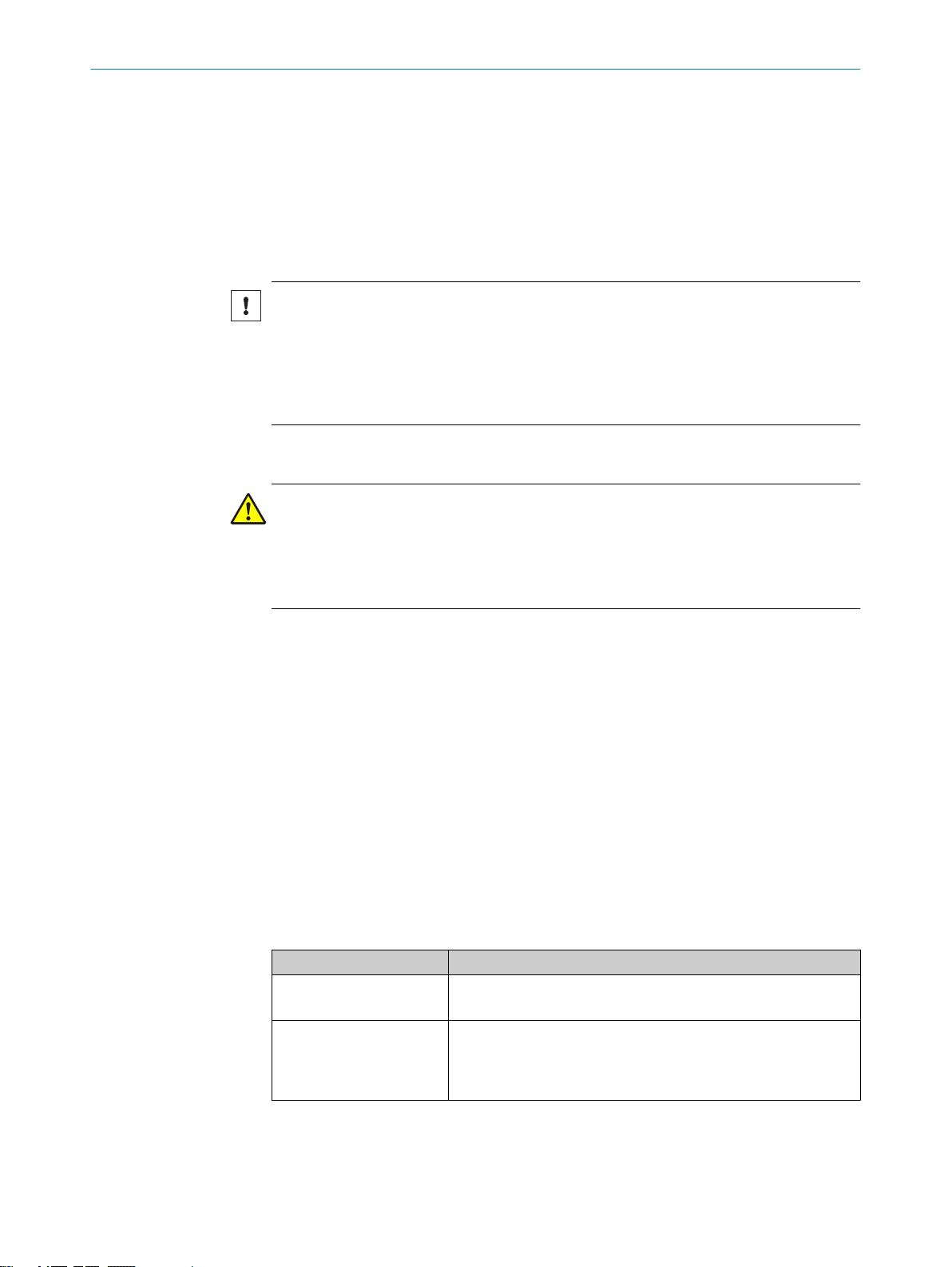
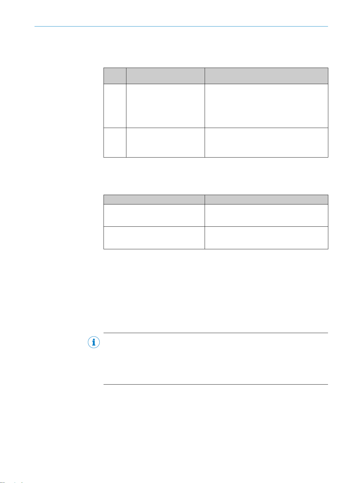
The following qualifications are required for various activities:
Table 1: Activities and technical requirements
Activities Qualification
Mounting, maintenance
Electrical installation,
device replacement
Basic practical technical training
■
Knowledge of the current safety regulations in the workplace
■
Practical electrical training
■
Knowledge of current electrical safety regulations
■
Knowledge of the operation and control of the devices in their
■
particular application
12
O PE R AT I NG IN S TR U CT I ON S | RFU62x 8015930/ZTM0/2018-11-06 | SICK
Subject to change without notice
Page 13
Activities Qualification
Commissioning, configura‐
tion
Basic knowledge of the WindowsTM operating system in use
■
Basic knowledge of the design and setup of the described con‐
■
nections and interfaces
Basic knowledge of data transmission
■
Basic knowledge of RFID technology (identification with radio-
■
based data cards)
Operation of the device for
the particular application
Knowledge of the operation and control of the devices in their
■
particular application
Knowledge of the software and hardware environment for the
■
particular application
2.7 Operational safety and particular hazards
Please observe the safety notes and the warnings listed here and in other chapters of
these operating instructions to reduce the possibility of risks to health and avoid dan‐
gerous situations.
WARNING
Electrical voltage!
Electrical voltage can cause severe injury or death.
■
Work on electrical systems must only be performed by qualified electricians.
■
The power supply must be disconnected when attaching and detaching electrical
connections.
■
The product must only be connected to a voltage supply as set out in the require‐
ments in the operating instructions.
■
National and regional regulations must be complied with.
■
Safety requirements relating to work on electrical systems must be complied with.
SAFETY INFORMATION 2
WARNING
Dangerous equipotential bonding currents!
Improper grounding can lead to dangerous equipotential bonding currents, which may
in turn lead to dangerous voltages on metallic surfaces, such as the housing. Electrical
voltage can cause severe injury or death.
■
Work on electrical systems must only be performed by qualified electricians.
■
Follow the notes in the operating instructions.
■
Install the grounding for the product and the system in accordance with national
and regional regulations.
8015930/ZTM0/2018-11-06 | SICK OP E RA T IN G I N ST R UC T IO N S | RFU62x
Subject to change without notice
13
Page 14

2 SAFETY INFORMATION
WARNING
High-frequency electromagnetic radiation!
High-frequency electromagnetic radiation poses a potential health risk.
The RFU62x-10x00 1) device is designed for operation according to ETSI EN 302208.
During operation, the human exposure regulations covered by EN 50364 must be
observed.
■
The RFU62x-10x01 1) device satisfies the limit values of the FCC for exposure to radia‐
tion in an uncontrolled environment.
■
2.8 Repairs
In order to limit human exposure to electromagnetic fields, suitable safety dis‐
tances must be maintained during both short-term and long-term work in the radi‐
ation range of the internal antenna.
The minimum distance to be maintained between the device and the human body
during long-term transmission: 10 cm and max. radiation power of the antenna of
250 mW ERP (24 dBm) as per ETSI.
During operation, a safety distance of at least 20 cm must be maintained between
the device and the human body.
Repair work on the device may only be performed by qualified and authorized person‐
nel from SICK AG. Interruptions or modifications to the device by the customer will inval‐
idate any warranty claims against SICK AG.
1)
For regional assignment, see the type-specific online data sheet in the Internet at: www.sick.com/RFU62x
14
O PE R AT I NG IN S TR U CT I ON S | RFU62x 8015930/ZTM0/2018-11-06 | SICK
Subject to change without notice
Page 15
3 Product description
1
2
3
4
5
6
SICK AG, D-22143 Hamburg
Made in Germany
Manufactured: May 2016
0700
RFU6xx-xxxxx
DC 10...30V <26W
16410240
1062600
Type:
P/N:
MAC:
Power:
S/N:
00:00:00:00:00:00
6
1
2
3
4
5
RFU6xx-xxxx1
DC 12...30V <26W
1620 0001
1054397
Type:
P/N:
MAC:
Power:
S/N:
00:00:00:00:00:00
This device complies with Part 15 of
the FCC rules. Operation is subject to
the following two conditions:
(1) this device may not cause
harmful interference, and
(2) this device must accept any inter ference received, including interference
that may cause undesired operation.
SICK AG, D-22143 Hamburg
Made in Germany
Manufactured: May 2016
Proc. Cont. Eq.
E336916
3.1 Product ID
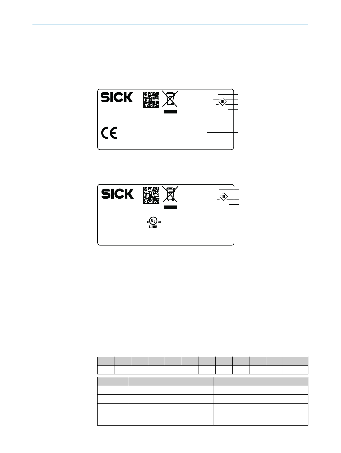
3.1.1 Type label
The type label gives information for identification of the device.
Figure 1: Structure of the type label
The UL certification is dependent on the type. An existing UL certification can be found
on the type label.
PRODUCT DESCRIPTION 3
3.1.2 Type code
8015930/ZTM0/2018-11-06 | SICK OP E RA T IN G I N ST R UC T IO N S | RFU62x
Subject to change without notice
Figure 2: Structure of the type label with UL symbol
Type designation
1
Part number
2
Serial number
3
Supply voltage and power consumption
4
MAC address (placeholder)
5
Approval-related details (region-specific)
6
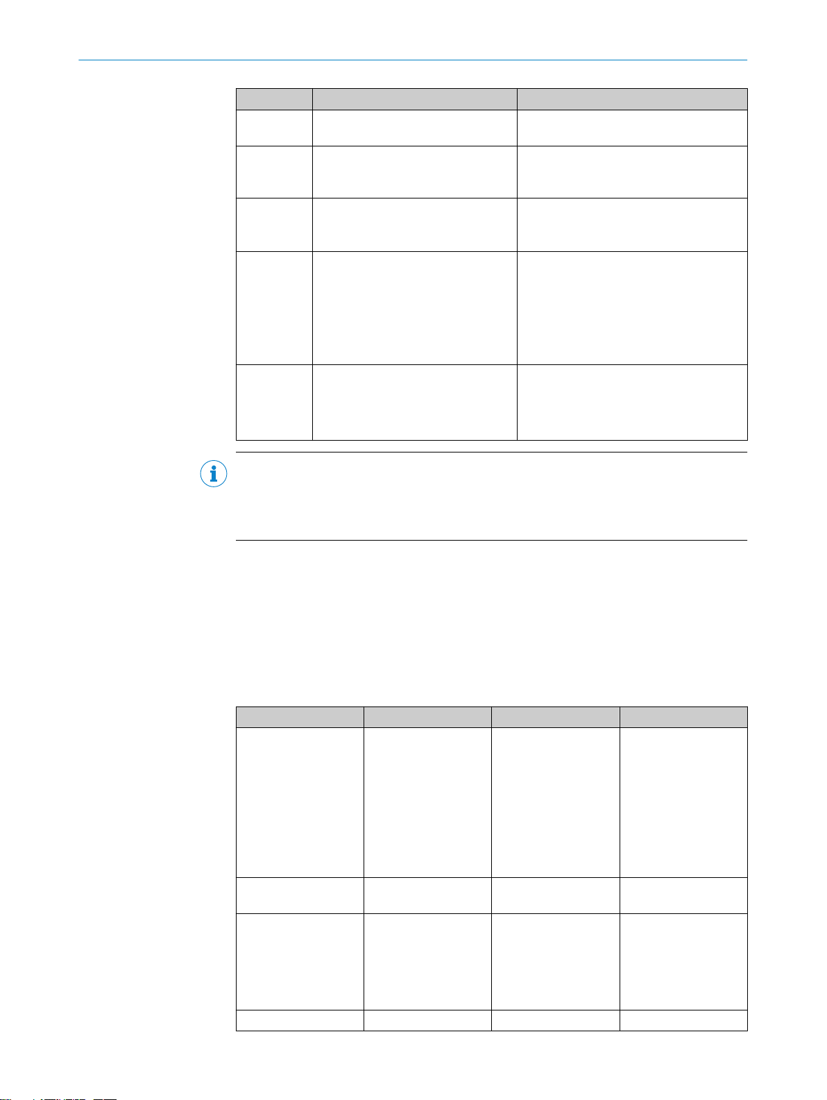
The devices of the RFU6xx product family are arranged according to the following type
code:
RFUxyz-abcde
R F U x y z - a b c d e
1 2 3 4 5 6 7 8 9 10 11
Position Description Characteristic
1 ... 2 RF (Radio Frequency Identification) –
3 Frequency band U: Ultra High Frequency
4 ... 5 Product family/version (working
range)
62: ≤2 m (Mid Range)
63: ≤10 m (Long Range)
65: ≤10 m (Long Range)
15
Page 16
3 PRODUCT DESCRIPTION
Position Description Characteristic
6 Device type 0: Base type (EPCglobal UHF Class 1 Gen‐
7 Internal antenna 0: No internal antenna
8 Connections for external antennas 0: No connection
9 Electrical connections 1: 1 x male connector, M12, 17-pin, A-
10 ... 11 Country-specific radio equipment
approval
eration 2, ISO/IEC 18000-6C)
1: With internal antenna, circularly polar‐
ized
3: Three connections
4: Four connections
coded; 1 x female connector, M12, 4-pin,
D-coded
4: Cable with male connector, D-Sub-HD,
15-pin
5: 1 x female connector, M12, 8-pin, Xcoded
00: Europe ...
Type-dependent, see type-specific online
data sheet at:
www.sick.com/RFU62x
•
3.1.2.1 Device variants
NOTE
Not all combinations are possible according to the type code. The available device vari‐
ants can be found online at:
www.sick.com/RFU62x
•
The RFU62x product family consists of 3 variant lines:
RFU62x-101xx (Ethernet variant)
•
RFU62x-104xx (serial variant)
•
RFU62x-105xx (PoE variant)
•
The variant lines differ with respect to the following features:
Table 2: Differences between the variant lines
Feature RFU62x-101xx RFU62x-104xx RFU62x-105xx
Electrical Interfaces
Supply voltage DC 10 V... 30 V
Type of electrical con‐
nections
Enclosure rating IP67 IP65 IP67
Power
•
Serial Data
•
CAN
•
2 digital switching
•
inputs
2 digital switching
•
outputs
Ethernet
•
2)
USB
•
DC 20 ... 30 V
1 x male connec‐
•
tor, M12, 17-pin, Acoded
1 x female connec‐
•
tor, M12, 4-pin, Dcoded
Power
1)
3)
•
Serial Data
•
CAN
•
2 digital switching
•
inputs
2 digital switching
•
outputs
USB
•
DC 10 V... 30 V DC 48/57 V
0.9 m cable with 1
•
x male connector,
D-Sub-HD, 15-pin
1)
2)
Power
•
Ethernet
•
2)
USB
•
1 x female connec‐
•
tor, M12, 8-pin, Xcoded
16
O PE R AT I NG IN S TR U CT I ON S | RFU62x 8015930/ZTM0/2018-11-06 | SICK
Subject to change without notice
Page 17

PRODUCT DESCRIPTION 3
Feature RFU62x-101xx RFU62x-104xx RFU62x-105xx
Ambient operating
temperature
1)
Host: RS-232/RS-422/485, Aux: RS -232.
2)
USB interface for temporary use only as a servicing interface.
3)
For ambient operating temperature below –25 °C.
All device variants include an internal antenna of identical design. It is not possible to
connect an external antenna.
Within the same variant line, the device types differ with respect to the following regionrelated, non-modifiable features:
Radio equipment approval
•
Carrier frequency range
•
Maximum transmitting power of the internal antenna
•
–40 °C ... +50 °C –25 °C ... +50 °C –25 °C ... +50 °C
8015930/ZTM0/2018-11-06 | SICK OP E RA T IN G I N ST R UC T IO N S | RFU62x
Subject to change without notice
17
Page 18
Ready
ResultRFData
CAN
LNK/ACT
Micro-SD
Micro-SD
ResultRFData
CAN
LNK/ACT
Ready
100°
34.4
(1.35)
20.1
(0.79)
20.1
(0.79)
20.1
(0.79)
50 (1.97)
25
(0.98)
25
(0.98)
130.8 (5.15)
130.8 (5.15)
6 x 7.7 (0.30)
137.4 (5.41)
54 (2.13)
18.1
(0.71)
55.3
(2.18)
7
(0.28)
30
(1.18)
25.5
(1.00)
71.9 (2.83)
76.7 (3.02)
71.9
(2.83)
71.9
(2.83)
76.9
(3.03)
69.7
(2.74)
1 2
3
4
5
6
7
8
9
ß à
á
â
ã
113.9 (4.48)
103.3 (4.07)
116 (4.57)
RFU620-101xx
RFU620-105xx
RFU620-104xx
RFU620-101xx
RFU620-105xx
RFU620-104xx
3 PRODUCT DESCRIPTION
3.2 Product characteristics
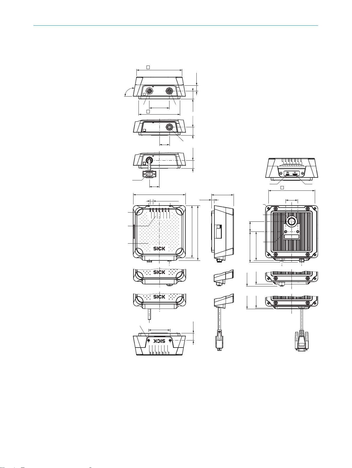
3.2.1 Device view
Figure 3: RFU620 (all variants): design and device dimensions, all dimensions in mm or inch
“Power/Serial Data/CAN/I/O” connection (male connector, M12, 17-pin, A-coded)
1
“Ethernet” connection (female connector, M12, 4-pin, D-coded)
2
“PoE” connection (female connector, M12, 8-pin, X-coded)
3
“Power/Serial data/CAN/I/O” connection (male connector, D-Sub-HD, 15-pin), cable
4
0.9 m
4 x LED, multi-colored (process feedback)
5
7 x LED, multi-colored (status indicator)
6
Cover with internal antenna
7
2 x screw (Torx T8), captive, for side cover
8
18
O PE R AT I NG IN S TR U CT I ON S | RFU62x 8015930/ZTM0/2018-11-06 | SICK
Subject to change without notice
Page 19
–28
–25
–22
–19
–16
–13
–10
–7
–4
–1
2
0°
15°
30°
45°
60°
75°
90°
105°
120°
135°
150°
165°
180°
–165°
–150°
–135°
–120°
–105°
–90°
–75°
–60°
–45°
–30°
–15°
5
2
1
PRODUCT DESCRIPTION 3
Side cover open
9
“USB” connection (female connector, 5-pin, type Micro-B), servicing interface for tempo‐
ß
rary use only
Slot for microSD memory card
à
4 x M5 blind tapped holes, 9 mm deep, for alternative mounting of the device
á
Pressure compensation valve (ventilation element)
â
2 x M6 blind tapped holes, 6 mm deep for mounting the device
ã
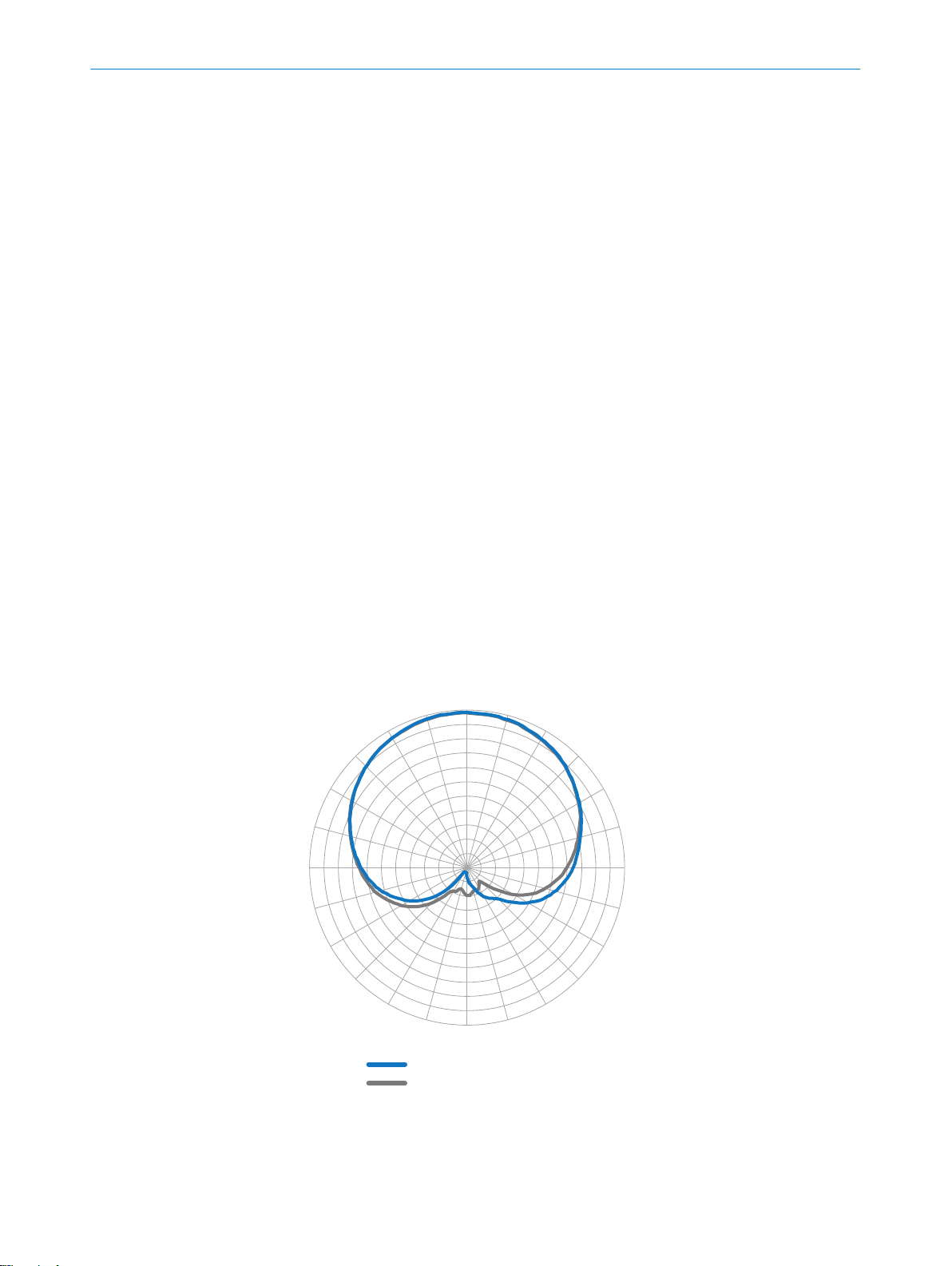
3.2.2 Working range of the antenna (sensing range of the reading and writing field)
The UHF field is influenced by its environment, making it impossible to provide a “clear”
demarcation of the sensin range:
Application-specific reflections can result in both overreaches and “holes”
•
(destructive interferences).
Other factors that can significantly impact the sensing range include:
•
Quality of the transponder (antenna gain, the integrated transponder IC and
°
related sensitivity, reflected energy)
Material of the carrier object (plastic, wood, metal)
°
Objects between the device and transponder that can affect the UHF field
°
(items, liquids, people)
In addition to the read results, the RFU device can also output diagnostic data that pro‐
vide an indication of the write and read quality. This data can be used to achieve opti‐
mum read results when setting up the system.
The radiation pattern shown here for the device’s antenna was obtained in a repro‐
ducible environment (absorber chamber as a reflection-free space) for illustrative pur‐
poses. It may therefore only have limited applicability to your specific application. The
diagram shows how the UHF field propagates in a reflection-free space, but cannot be
used to draw any conclusions on the likely sensing range in a real on-site application.
Figure 4: Radiation pattern of the internal antenna of the RFU620 (typical): Measured antenna
gain in dBic at 866.5 MHz, RHCP (right-hand circularly polarized)
1
8015930/ZTM0/2018-11-06 | SICK OP E RA T IN G I N ST R UC T IO N S | RFU62x
Subject to change without notice
2
Azimuth plane (horizontal)
Elevation plane (vertical)
19
Page 20
3 PRODUCT DESCRIPTION
3.2.3 Scope of delivery
The delivery of the device includes the following components:
Table 3: RFU62x: scope of delivery
No. of
units
1 Device in the version ordered
1)
Serial variant. The device has a connecting cable with a D-Sub-HD male connector that is permanently
connected to the housing.
Associated components not contained in the delivery:
Table 4: RFU62x: Other components
Component Notes
SOPAS ET configuration software and
device description file (*.sdd-file) for the
RFU62x
RFU62x operating instructions as PDF in
English and German. Other languages
also available online where applicable.
Component Notes
RFU62x-104xx 1):
(variant line and region assign‐
ment)
Device type-dependent, printed
Quick Start Guide. The number
of enclosed language versions
depends on the country
Without bracket.
RFU62x-101xx and RFU62x-105xx:
M12 electrical connections sealed with protective
plugs or caps that are screwed tight.
Without connecting cables and bracket.
All available language versions of the Quick Start
Guide can also be found online as PDFs at:
www.sick.com/RFU62x
•
Available online at:
www.sick.com/SOPAS_ET
•
Available online at:
www.sick.com/RFU62x
•
Accessories
The following accessories for constructing a complete RFID read/write station are not
included in the scope of delivery. They must be ordered separately as required:
Read cycle trigger sensor, e.g. photoelectric retro-reflective sensor for object-spe‐
•
cific triggering
CDB or CDM connection module or CDF fieldbus module
•
Suitable number of transponders depending on the application
•
3.2.4 Product features and functions (overview)
NOTE
In addition to the existing operating instructions, the use of the RFU parameter descrip‐
tion is recommended. This document explains the UHF-RFID-specific parameters of all
device variants of the RFU6xx product family at the "Service” user level.
The parameter description supports the user in configuring applications with the
SOPAS ET configuration software.
The parameter description is available in English (part no. 8023085) and German (part
no. 8023084) as well as other languages if required.
The RFU parameter description can be found on the online product page at:
www.sick.com/RFU62x
•
20
O PE R AT I NG IN S TR U CT I ON S | RFU62x 8015930/ZTM0/2018-11-06 | SICK
Subject to change without notice
Page 21

PRODUCT DESCRIPTION 3
Table 5: Overview of product features and functions of the device
Product feature/func‐
tion
Security and ease of
use
Convenient operation/
configuration
Reading Operation
Mode
Read cycle
Radio interface(s)
Transponder Process‐
ing
Transponder Manage‐
ment
Characteristic
Rugged, compact metal housing, CE marking (Europe)
•
Automatic self-test at system start
•
Diagnostic tools for device setup and (remote) device monitoring
•
Configurable output of the read results including read diagnostics
•
data in two output formats
Operating data polling and, in the event of an error, output of codi‐
•
fied error messages on request
Activatable test string function (heartbeat) to signal that the device
•
is ready for operation
Future-proof due to firmware update via data interface
•
Future-proof SOPAS ET configuration software with password-pro‐
•
tected configuration mode
SICK AppSpace ready: The device already includes sensor apps for
•
integrating it into existing communication networks
Low power consumption
•
Wide supply voltage range
•
Large ambient temperature range. For details, see "Technical data",
•
page 82
Parameter cloning (to back up the configuration data in the internal
•
device memory):
Externally by inserting a microSD memory card 1) into the device
°
Externally via the CMC600 parameter cloning module1) in the
°
CDB 1) or CDM 1) connection module (function not supported for
RFU62x-105x)
Configuration (online/offline) using the SOPAS ET configuration soft‐
•
ware
Single Tag ID Wizard (assistant) to help with initial configuration
•
Configuration and starting of device functions via a web server or
•
command strings
Optional function blocks for easier integration into PLC programs
•
PROFINET single port (RFU62x-101xx, RFU62x-105xx): Configura‐
•
tion via GSD parameterization
Application-specific programming using the SICK AppStudio devel‐
•
opment environment.
Further information on this is available online at: www.sick.com/
SICK_AppStudio
Status and process feedback indicators via LEDs
•
Start/stop operation: For reading one or more transponders during
•
a read cycle.
Read cycle start condition is configurable in the object trigger con‐
•
trol settings: switching inputs etc.
Read cycle stop condition is configurable in the object trigger con‐
•
trol settings: switching inputs etc.
Internal antenna
•
Base model RFU620 supports all standard passive transponders
•
that are compatible with EPCglobal UHF Class 1 Generation 2 or
ISO/IEC-18000-6C
Reading, writing, and multiple overwriting of the data on the
•
transponders, depending on the application
The data-supplying device is a component of a system for complete
•
visualization of the data within the process chain
Decoding of the UII in HEX, BIN and ASCII. Supports GS1 TDS and
•
other industry-specific standards such as VDA55xx.
8015930/ZTM0/2018-11-06 | SICK OP E RA T IN G I N ST R UC T IO N S | RFU62x
Subject to change without notice
21
Page 22

3 PRODUCT DESCRIPTION
Product feature/func‐
tion
Data processing
Data communication
Electrical Interfaces
Connectivity (Design)
1)
Optional accessories.
2)
Interface for temporary use only as a servicing interface.
Characteristic
Variable read data output based on event-dependent evaluation
•
conditions
Influencing the output string by filtering and output sorting
•
Implementation of application-specific data output protocols using
•
the SICK AppStudio development environment (flexible back-end
integration)
Host interface: two configurable data output formats. Switchable to
•
different physical or logical interfaces. Parallel operation possible.
For outputting data to a further-processing computer.
Aux interface: fixed data output format. Switchable to different phys‐
•
ical or logical interfaces. For device configuration and diagnostics
as well as transponder access.
Host interface
•
RS-232, RS-422/485 (configurable data format and protocol),
°
CAN. These interfaces are not available for RFU62x-105xx (PoE
variant).
Ethernet (supported protocols include, amongst others,
°
PROFINET single port). This interface is not available for
RFU62x-104xx (serial variant)
Aux interface
•
RS-232 (fixed data format, data transmission rate and protocol).
°
This interface is not available for RFU62x-105xx (PoE variant).
Ethernet (interface is not available for RFU62x-104xx, serial vari‐
°
ant), USB
CAN interface for integrating the device into the SICK-specific CAN-
•
SENSOR network. Interface not available for RFU62x-105xx.
2 digital switching inputs (interfaces not available for
•
RFU62x-105xx)
2 digital switching outputs (interfaces not available for
•
RFU62x-105xx)
Expandable with 2 software-controlled digital switching inputs and
•
outputs respectively via the CMC600 parameter cloning module1) in
the CDB 1) or CDM 1) connection module (function not available for
RFU62x-105xx)
RFU62x-101xx: 2 x M12 male circular connector, 1x USB (type
•
Micro-B)
RFU62x-104xx: 1 x cable with 15-pin D-Sub-HD male connector, 1x
•
USB (type Micro-B)
RFU62x-105xx: 1 x M12-male circular connector, 1 x USB (type
•
Micro-B)
2)
3.2.5 Memory card
22
O PE R AT I NG IN S TR U CT I ON S | RFU62x 8015930/ZTM0/2018-11-06 | SICK
NOTE
The memory card is an optional accessory and is not included in the scope of delivery.
Functions
The device can execute the following functions on the plug-in microSD memory card:
Saving the parameter set (cloning function)
•
Semi-automatic, additional storage of the internal parameter set (device configura‐
tion data) on an external memory medium. This takes place in the framework of
the recommended backup concept for the 4Dpro device parameter sets.
Subject to change without notice
Page 23
PRODUCT DESCRIPTION 3
This function is initiated by using the “permanent” option to save the internal
°
parameter set, e.g. via the SOPAS ET configuration software.
The function is used, among other things, to conveniently transfer the para‐
°
meter set to an replacement device of the same type in the event of an fault.
Optional external media include a microSD memory card that can be inserted
°
into the device, or the CMC600 parameter storage module in the CDB or
CDM connection module. Only the microSD memory card option is available
for the RFU62x-105xx.
Recording of diagnostic read data
•
Continuous recording of diagnostic read data after the first manual start, e.g., via
SOPAS ET. Recording is resumed after a device restart if the function has been
permanently set.
Other functions on request.
•
We recommend using an empty memory card when storing a parameter set for the first
time (if necessary, use a PC and card reader to check and delete the contents of the
card).
NOTE
Only use types approved by SICK to ensure reliable function of the memory card. You
can find these as accessories online at:
www.sick.com/RFU62x
•
The memory cards have no write protection that can be activated.
Indication of operational readiness
The “microSD” optical indicator shows the status of the memory card after installation
in the device. It lights up in different colors according to the status, see "Optical status
indicators on the display panel", page 71.
NOTICE
Possible data loss!
When the indicator is green (operational), this does not mean that the device is actually
accessing the memory card for reading or writing.
Do not remove the memory card or switch off the supply voltage while the device is
b
performing the following actions via the SOPAS ET configuration software:
■
Changing the parameter values by saving using the “permanent” option.
■
Starting functions that access the memory card (e.g. concurrent logging of
data)
Inserting the memory card in the device:
NOTICE
Risk of damage to the memory card!
To safely install the memory card, make sure there is no power to the device
b
before you insert it.
Ensure the IP67 or IP65 enclosure rating of the device is maintained, see "Conditions
for specified enclosure rating", page 11.
The card slot on the device is located under the cover foil on the side opposite the con‐
nections.
8015930/ZTM0/2018-11-06 | SICK OP E RA T IN G I N ST R UC T IO N S | RFU62x
Subject to change without notice
23
Page 24
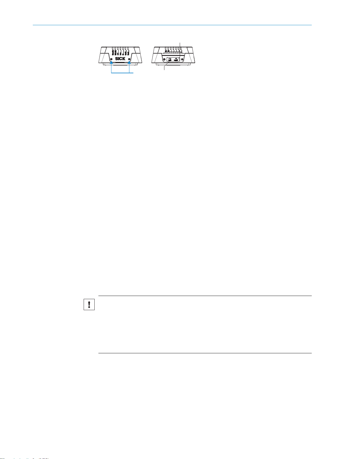
3 2
1
3 PRODUCT DESCRIPTION
Figure 5: USB connection and slot for microSD memory card
1
2
3
1. Switch off the supply voltage to the device.
2. Loosen both screws on the cover.
3. Carefully fold up the cover.
4. Making sure it is in the correct position, insert the memory card into the slot until
5. Screw the cover back on. Recommended tightening torque for the cover screws:
6. Switch on the supply voltage for the device.
Slot for microSD memory card
USB port (female connector, Micro-B, 5-pin)
2 x screw, Torx T8
it locks into place. When doing so, orient the contacts so that they are facing
towards the device and downwards as per the symbol on the device.
60 Ncm ± 5 Ncm.
Interpretation of the stored parameter set
The device automatically detects that a memory card has been inserted and, depend‐
ing on the card’s content, behaves as follows:
■
If the card is empty or if it contains a parameter set that cannot be interpreted by
the device, the device saves its currently valid internal parameter set to the card
(provided there is sufficient storage space) and starts with the internal parameter
set.
■
If the card contains a parameter set that can be interpreted by the device, the
device overwrites the currently valid, permanently saved internal parameter set
with this external parameter set.
■
The goal is for the internal parameter set and the parameter set saved externally
to always be identical.
Removing the memory card from the device:
NOTICE
Risk of damage to the memory card!
To safely remove the memory card while the device is in operation:
b
In SOPAS ET, execute the Remove SD card command under Analysis/SD card and
°
wait for SOPAS ET to provide confirmation.
If this command is not accessible, the memory card can also be removed
°
when there is no power to the device.
24
O PE R AT I NG IN S TR U CT I ON S | RFU62x 8015930/ZTM0/2018-11-06 | SICK
Subject to change without notice
Page 25
4 Transport and storage
4.1 Transport
For your own safety, please read and observe the following notes:
NOTICE
Damage to the product due to improper transport.
■
The device must be packaged for transport with protection against shock and
damp.
■
Recommendation: Use the original packaging as it provides the best protection.
■
Transport should be performed by trained specialist staff only.
■
The utmost care and attention is required at all times during unloading and trans‐
portation on company premises.
■
Note the symbols on the packaging.
■
Do not remove packaging until immediately before you start mounting.
4.2 Unpacking
■
Before unpacking, it may be necessary to equalize the temperature to protect the
device from condensation.
■
Handle the device with care and protect it from mechanical damage.
■
Remove the protective caps or protective plugs on the electrical connections
immediately before connecting the connecting cable to prevent dirt and moisture
from entering.
TRANSPORT AND STORAGE 4
4.3 Transport inspection
Immediately upon receipt in Goods-in, check the delivery for completeness and for any
damage that may have occurred in transit. In the case of transit damage that is visible
externally, proceed as follows:
■
Do not accept the delivery or only do so conditionally.
■
Note the scope of damage on the transport documents or on the transport com‐
pany's delivery note.
■
File a complaint.
NOTE
Complaints regarding defects should be filed as soon as these are detected. Damage
claims are only valid before the applicable complaint deadlines.
4.4 Storage
Store the device under the following conditions:
■
Recommendation: Use the original packaging.
■
Electrical connections are provided with protective caps and plugs (as they are on
delivery).
■
Do not store outdoors.
■
Store in a dry area that is protected from dust.
■
So that any residual damp can evaporate, do not package in airtight containers.
■
Do not expose to any aggressive substances.
■
Protect from sunlight.
■
Avoid mechanical shocks.
■
Storage temperature: see "Technical data", page 82.
8015930/ZTM0/2018-11-06 | SICK OP E RA T IN G I N ST R UC T IO N S | RFU62x
Subject to change without notice
25
Page 26

4 TRANSPORT AND STORAGE
■
Relative humidity: see "Technical data", page 82.
■
For storage periods of longer than 3 months, check the general condition of all
components and packaging on a regular basis.
26
O PE R AT I NG IN S TR U CT I ON S | RFU62x 8015930/ZTM0/2018-11-06 | SICK
Subject to change without notice
Page 27

5 Mounting
5.1 Overview of mounting procedure
The procedure for mounting the device is divided into the following steps:
1. Select a suitable mounting location for the device.
The mounting location and position depend on the following factors:
Identification task
°
Working range of the device (see "Working range of the antenna (sensing
°
range of the reading and writing field)", page 19)
Transponder used
°
Environmental influences
°
2. Mount the device at the intended reading location and at a suitable distance from
the object with the transponder, then approximately align the device with the
object.
3. If required, mount the read-cycle sensor for object-specific triggering.
After the electrical installation is complete and while adjusting the device parameters to
suit the application:
4. Finely align the device to the object and adjust it.
5. Test for successful reading and writing in actual operation.
MOUNTING
5
5.2 Preparation for mounting
5.2.1 Installation requirements
Space requirements
■
For the typical space requirements, see the:
■
Dimensional drawing for the device variant see "Device view", page 18 and sens‐
ing range of the internal antenna see "Working range of the antenna (sensing
range of the reading and writing field)", page 19.
The device does not require any physical or visual contact with the transponders. It
does, however, need to be aligned with the reading space.
Environmental influences
■
Comply with technical data, such as the permitted ambient conditions for opera‐
tion (e.g. approved region, ambient temperature range, ground potential),
■
To prevent condensation, avoid exposing the device to rapid changes in tempera‐
ture.
■
To prevent additional external heating of the device, protect the device against
direct sunlight.
■
To avoid reflection of the UHF waves and the resultant possibility of overreaches or
“holes” (destructive interferences) in the UHF field, try to ensure that there are no
metal surfaces located to the side of the device in the direction of the transpon‐
der.
■
To avoid damping of the UHF field due to absorption, do not allow any electrically
conductive material such as liquids (water) or persons to come between the device
and the transponder
Mounting
■
The device must be mounted using all of the blind tapped holes of the selected
thread size provided.
■
Mount the device in a shock and vibration insulated manner.
8015930/ZTM0/2018-11-06 | SICK OP E RA T IN G I N ST R UC T IO N S | RFU62x
Subject to change without notice
27
Page 28
5 MOUNTING
5.2.2 Instructions for mounting the device when the ambient temperature can fall below 0 °C
NOTE
For the electrical installation procedure, see "Instructions for electrical installation when
the ambient temperature can fall below 0 °C", page 49
All device variants can also be operated at low ambient temperatures. For details, see
"Technical data", page 82
NOTICE
Operating the device at the lower limit of the permissible ambient temperature range
The ensure the device can produce the required heating power, do not expose the
device to strong air flows (e.g. from a ventilation system).
If necessary, take appropriate measures to shield the device from air flows.
b
NOTICE
If the ambient temperature is below 0 °C, please note:
Do not move the connecting cables to the device and optional CDB or CDM con‐
•
nection module or CDF600 fieldbus module
Do not operate the configuration switch on the optional connection module or
•
fieldbus module
5.2.3 Auxiliary equipment required
■
Mounting device (bracket) with sufficient load-bearing capacity, see "Technical
data", page 82 and suitable dimensions see "Device view", page 18.
■
4 x M5 or 2 x M6 screws for mounting the device.
NOTE
The screws are for mounting the device on mounting equipment (bracket) supplied
by the user. The screw length required depends on the mounting base (wall thick‐
ness of the bracket).
When using an optional SICK bracket, the screws for mounting the device on the
bracket are included in the scope of delivery of the bracket.
NOTICE
Risk of damage to the device!
M5 blind tapped holes: Do not exceed the maximum screw-in depth of 9 mm!
•
M6 blind tapped holes: Do not exceed the maximum screw-in depth of 6 mm!
•
■
Tool and tape measure
5.2.4 Mounting device
Optional SICK brackets
The device is mounted with the help of a minimum of two blind tapped holes, depend‐
ing on their diameter. The blind tapped holes come in 2 different thread sizes, and vary
in number. The blind tapped holes are located on the rear of the device, see "Device
view", page 18.
28
The device can be mounted using an optional SICK bracket, a combination of SICK
brackets and elements, or a customer-specific bracket.
SICK offers prefabricated brackets which are optimally suited for mounting the device
in a wide range of applications.
O PE R AT I NG IN S TR U CT I ON S | RFU62x 8015930/ZTM0/2018-11-06 | SICK
Subject to change without notice
Page 29
Fixed position 1 Variable position
(± 45°) 2
Variable position
(± 45°) 2
Fixed position 1 Fixed position 1
Variable position
(±45°) 2
MOUNTING
Also see on Internet at:
www.sick.com/RFU62x
•
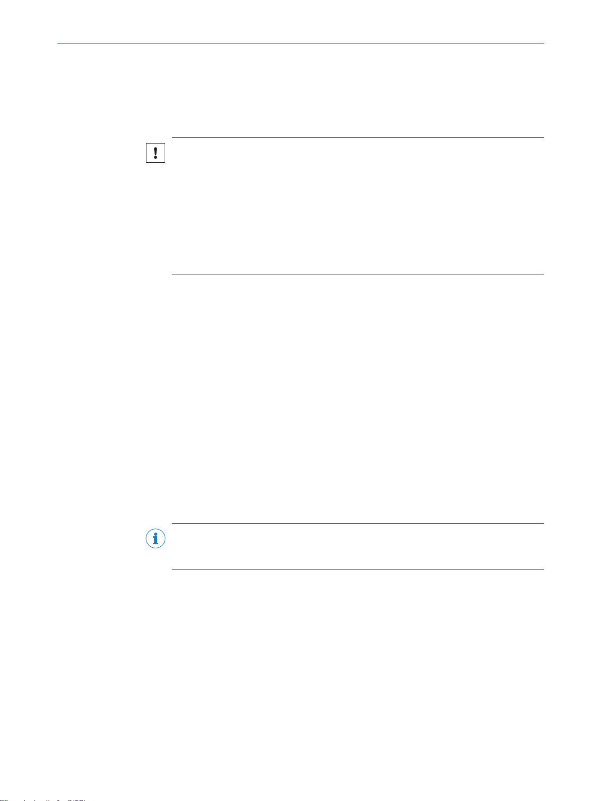
Example 1: The mounting bracket supports a variety of installation variants.
5
Figure 6: Mounting bracket: Installation examples (adjustment in 2 axes possible)
Fixed position
1
Variable position
2
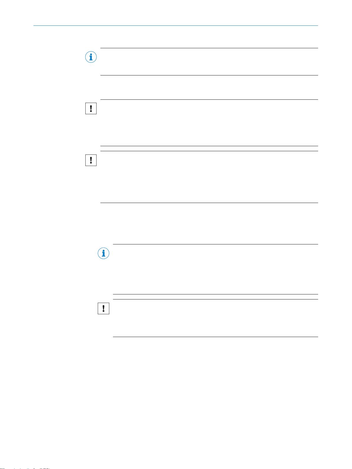
Example 2: A combination of VESA adapter plate, tube elements, and clamps enables
the device to be aligned in three axes.
8015930/ZTM0/2018-11-06 | SICK OP E RA T IN G I N ST R UC T IO N S | RFU62x
Subject to change without notice
29
Page 30
1 2
3
6
3
5
4
4
7
5 MOUNTING
Figure 7: Bracket made from tube elements and clamps in combination with a VESA adapter
plate, adjustment in 3 axes possible
VESA adapter plate part no. 2071862 with 2 x M6 x 12 countersunk head screws, hexa‐
1
gon socket (WAF 4)
Hinged clamp part no. 2068919 with 4 x M6 x 12 cylinder head screws, hexagon socket
2
(WAF 5)
Tube, external diameter 30 mm, length 1 m, part no. 5327610
3
Sealing plug, external diameter 30 mm, part no. 5327613
4
Cross clamp, part no. 5327612
5
Base clamp, part no. 5327611
6
Base (e.g. plate, supplied by the user)
7
NOTE
Dimensional drawings for SICK brackets and, if applicable, mounting instructions can
be found online at: www.sick.com
To do so, enter the 7-digit part number of the bracket in the search field.
b
User-supplied brackets
A user-supplied bracket should meet the following requirements:
■
Stable mounting device
– Allow the device to be aligned in the x and y axes.
– The mounting device must be able to bear the weight of the device, including
connecting cables, in a shock-proof manner, see "Technical data", page 82.
– In mounting situations with strong vibrations, it may be necessary to provide
shock mounts.
■
Suitable drill holes for mounting the device as per the dimensional drawing: two
for M6 screws or four for M5 screws.
30
O PE R AT I NG IN S TR U CT I ON S | RFU62x 8015930/ZTM0/2018-11-06 | SICK
Subject to change without notice
Page 31

5.3 Mounting location
When selecting the mounting location, the following factors are significant:
Spatial working range of the antenna
•
Distance to objects with a transponder
•
Influence of the environment on the UHF field produced, for example:
•
°
°
°
5.4 Mounting the device
WARNING
Risk of injury due to damage to the device
For reasons of safety, if a device shows visible signs of damage do not put it into opera‐
tion, or take it out of operation immediately. Damage includes, for example:
Housing: Cracked or broken
•
Electrical connections: cracks or detachment from the housing
•
Device with fixed cable: Damage to the cable outlet or cable itself
•
MOUNTING 5
Metal surfaces located to the side of and in the vicinity of the device
Electrically conductive liquids between the antenna and transponder
Persons between the antenna and transponder
NOTICE
Risk of damaging the device!
Observe the maximum screw-in depth of the blind tapped holes on the device. Longer
screws than specified damage the device.
Use screws of suitable length.
b
Basic arrangement of the device to the transponders
UHF transponders have dipole antennas and therefore preferential directions when
transmitting or receiving within the radiation field of the antenna. The transmitting and
receiving performance will be higher or lower depending on the orientation of the dipole
antenna of the transponder to the axis perpendicular to the antenna surface. The read‐
ing and writing rate and sensing range can therefore be subject to fluctuations.
NOTE
If the dipole antenna of the transponder is oriented lengthwise along the axis perpen‐
dicular to the antenna surface, no reading or writing of the transponder will be possible.
8015930/ZTM0/2018-11-06 | SICK OP E RA T IN G I N ST R UC T IO N S | RFU62x
Subject to change without notice
31
Page 32

5 MOUNTING
Figure 8: The optimal orientation of the transponder for good writing and reading results is
demonstrated here for an external UHF antenna
Mounting and aligning the device
NOTICE
Avoid mutual interference when operating several devices
When the reading ranges of several independently operated devices overlap, this can
lead to mutual impairment of the system performance of the devices.
To avoid these situations, each of the devices support a SyncMode feature.
SyncMode enables several devices connected to the same Ethernet network to synchro‐
nize their reading responses. SyncMode ensures that only one device at a time is per‐
forming a read operation and therefore communicating over the air interface.
SyncMode is available for all devices in the RFU6xx product family that have an Ether‐
net interface.
SyncMode is not supported for RFU62x-104xx devices (serial variant).
1. Prepare the base for mounting the bracket of the device, see "Preparation for
mounting", page 27.
Recommendation: Depending on the application it may be possible to use one of
the optional SICK brackets. If necessary, perhaps also in combination with other
SICK brackets.
2. At the intended reading location, place an object with transponder within the work‐
ing range of the device (static object only).
3. Mount the device bracket onto the base.
4. Tighten screws through the bracket into the blind tapped holes of the device and
slightly tighten.
5. Orient the front side of the device towards the object.
32
O PE R AT I NG IN S TR U CT I ON S | RFU62x 8015930/ZTM0/2018-11-06 | SICK
Subject to change without notice
Page 33

Ensure, where possible, that there are no large metal surfaces located in
10°
1
°
front of the device.
If this is unavoidable, do not mount the device in the same plane as the sur‐
°
face but rather at an angle of inclination of approx. 10°.
Figure 9: Selected angle of inclination of the device when there is a large metal sur‐
face in front, e. g. 10°
Metal surface
1
6. Tighten the screws.
✓
The device is approximately aligned with the object to be detected.
7. Check the general suitability of the alignment for objects of different sizes and
varying positions of the transponder in actual operation.
5.5 Mounting external components
MOUNTING 5
5.5.1 Mounting the connection module or fieldbus module
If the device is controlled via a CDB or CDM connection module or CDF fieldbus mod‐
ule, mount the module in the vicinity of the device (RFU62x-101xx, RFU620-104xx).
NOTE
If the PC with the SOPAS ET configuration software accesses the Aux interface (RS-232;
57.6 kBd) of the device via the connection module or fieldbus module, do not locate
the connection module more than a 5 m cable length from the device.
1. Mount the connection module or fieldbus module in the vicinity of the device.
2. Mount the modules in such a way that the fieldbus module or open connection
module are accessible at all times.
NOTE
For detailed information on mounting and electrical installation, please refer to the
respective operating instructions for the connection module and fieldbus module.
These are available online at:
www.sick.com/CDB
•
www.sick.com/CDM
•
www.sick.com/CDF600
•
www.sick.com/CDF600-2
•
5.5.2 Mounting the external read cycle trigger sensor
Conveying line
If the detection of objects with transponders by the device (RFU62x-101xx,
RFU620-104xx) is triggered via an external trigger sensor (e.g. photoelectric retro-reflec‐
tive sensor), mount the trigger sensor at a suitably close distance to the device.
NOTE
A large selection of photoelectric sensors and accessories (brackets, connecting
cables) can be found online at: www.sick.com
8015930/ZTM0/2018-11-06 | SICK OP E RA T IN G I N ST R UC T IO N S | RFU62x
Subject to change without notice
33
Page 34

6 ELECTRICAL INSTALLATION
6 Electrical installation
6.1 Safety
6.1.1 Notes on electrical installation
Electrical installation must only be performed by electrically qualified personnel.
•
Standard safety requirements must be observed when working on electrical sys‐
•
tems!
Electrical connections between the device and other devices may only be made or
•
separated in a voltage-free state. Otherwise, there is a risk of damaging the
devices.
All connection work must be performed at ambient temperatures above 0 °C, see
•
"Ambient data", page 85
Connect the device to the permissible supply voltage only, see "Connecting the
•
supply voltage", page 55.
Only switch on the supply voltage to the device (or optional connection module or
•
fieldbus module depending on the type), after first:
Completing the connection work
°
Carefully checking the wiring work
°
Where connecting cables with one end open are concerned, make sure that bare
•
wire ends are not touching (risk of short circuit when the supply voltage is switched
on). Wires must be appropriately insulated from each other. This also applies to
unused wires.
The wire cross-sections in the supply cable from the user’s power system must be
•
selected in accordance with the applicable national standards. When this is being
done in Germany, observe the following standards: DIN VDE 0100 (Part 430) and
DIN VDE 0298 (Part 4) and/or DIN VDE 0891 (Part 1).
The wire cross-sections of the data and, if applicable, switching signal cables must
•
also be selected in accordance with the applicable national standards.
Circuits connected to the device must be designed as SELV circuits (SELV = Safety
•
Extra Low Voltage). The voltage supply must meet SELV requirements in accor‐
dance with the currently applicable standards, see "Mechanics and electronics",
page 84.
34
NOTE
For additional instructions on operating the device at ambient temperatures below
0 °C, see "Prerequisites", page 49
Data cables
NOTE
Layout of data cables
Use shielded data cables with twisted-pair wires.
•
The possible cable length between the device and host computer depends on:
•
the chosen physical version of the host interface
°
the data transmission rate set in the device
°
For further information, see "Wiring data interfaces", page 58.
Implement the shielding design correctly and completely.
•
To avoid interference, always use EMC-compliant cables and layouts. This applies,
•
for example, to cables for switched-mode power supplies, motors, clocked drives,
and contactors.
Do not lay cables in parallel with voltage supply cables or motor cables in cable
•
channels over longer distances.
O PE R AT I NG IN S TR U CT I ON S | RFU62x 8015930/ZTM0/2018-11-06 | SICK
Subject to change without notice
Page 35

ELECTRICAL INSTALLATION 6
Conditions for specified enclosure rating
To maintain the specified enclosure rating of the device (IP67 or IP65) during operation,
the following requirements must be met. If these requirements are not met, the device
does not fulfill any specified enclosure rating.
All variants:
•
The side cover for the USB socket and the microSD card slot must be screwed
tight to the device. Recommended tightening torque for the cover screws: 60 Ncm
±5 Nm.
RFU62x-101xx and RFU62x-105xx (both IP67):
•
The cables plugged into the electrical M12 connections must be clamped. Unused
M12 connections must be fitted with screw-on protective caps (for male connec‐
tors) or plugs (for female connectors) as supplied.
RFU62x-104xx (serial variant, IP65):
•
When lengthening the connecting cable of the device: use a suitable seal between
the male connector and female connector of the D-Sub pin connectors on each of
the cables and screw the pin connectors together. You can find a suitable IP65
rubber seal online at: www.sick.com/RFU62x
The same also applies to the EMC requirement (ESD) according to CE.
•
NOTICE
The device can, if necessary, be operated for a short time without the side cover to per‐
form the following tasks:
Inserting or removing the optional memory card
•
Temporary use of the USB interface as a servicing interface
•
During this time, protect the device against moisture and dust.
6.1.2 Prerequisites for safe operation of the device
WARNING
Risk of injury and damage caused by electrical current!
As a result of equipotential bonding currents between the device and other grounded
devices in the system, faulty grounding of the device can give rise to the following dan‐
gers and faults:
■
Metal housings are vulnerable to dangerous currents.
■
Devices will behave incorrectly or be destroyed.
■
Cable shielding will be damaged by overheating and cause cable fires.
Remedial measures
■
Only skilled electricians should be permitted to carry out work on the electrical sys‐
tem.
■
If the cable insulation is damaged, disconnect the voltage supply immediately and
have the damage repaired.
■
Ensure that the ground potential is the same at all grounding points.
■
Where local conditions do not meet the requirements for a safe earthing method,
take appropriate measures (e.g., ensuring low-impedance and current-carrying
equipotential bonding).
The device is connected to the peripheral devices (voltage supply, any local trigger sen‐
sor(s), system controller) via shielded cables. The cable shield – for the data cable,
for example – rests against the metal housing of the device. The device can be
grounded through the cable shield or through a blind tapped hole in the housing,
for example.
8015930/ZTM0/2018-11-06 | SICK OP E RA T IN G I N ST R UC T IO N S | RFU62x
Subject to change without notice
35
Page 36

SICK
Device
7 46
Power Supply
U
= 8
= 9
1 2 3
I
5
System
Controller
ELECTRICAL INSTALLATION
6
If the peripheral devices have metal housings and the cable shields are also in contact
with their housings, it is assumed that all devices involved in the installation have the
same ground potential.
This is achieved by complying with the following conditions:
■
Mounting the devices on conductive metal surfaces
■
Correctly grounding the devices and metal surfaces in the system
■
If necessary: low-impedance and current-carrying equipotential bonding between
areas with different ground potentials
Figure 10: Example: Occurrence of equipotential bonding currents in the system configuration
System controller
1
Device
2
Voltage supply
3
Grounding point 2
4
Closed current loop with equalizing currents via cable shield
5
Ground potential difference
6
Grounding point 1
7
Metal housing
8
Shielded electrical cable
9
If these conditions are not fulfilled, equipotential bonding currents can flow along the
cable shielding between the devices due to differing ground potentials and cause the
hazards specified. This is, for example, possible in cases where there are devices within
a widely distributed system covering several buildings.
Remedial measures
The most common solution to prevent equipotential bonding currents on cable shields
is to ensure low-impedance and current-carrying equipotential bonding. If this equipo‐
tential bonding is not possible, the following solution approaches serve as a suggestion.
NOTICE
We expressly advise against opening up the cable shields. This would mean that the
EMC limit values can no longer be complied with and that the safe operation of the
device data interfaces can no longer be guaranteed.
Measures for widely distributed system installations
On widely distributed system installations with correspondingly large potential differ‐
ences, the setting up of local islands and connecting them using commercially available
electro-optical signal isolators is recommended. This measure achieves a high degree
of resistance to electromagnetic interference.
36
O PE R AT I NG IN S TR U CT I ON S | RFU62x 8015930/ZTM0/2018-11-06 | SICK
Subject to change without notice
Page 37

Electro-
optical
signal
isolator
Electro-
optical
signal
isolator
Power
Supply
SICK
Device
1 2 2 43
6 5
System
Controller
= 7
= 8
= 9
U
System
Controller
Power Supply
SICK
Device
8 6
5
21 3
4
7
= 9
= ß
ELECTRICAL INSTALLATION 6
Figure 11: Example: Prevention of equipotential bonding currents in the system configuration by
the use of electro-optical signal isolators
System controller
1
Electro-optical signal isolator
2
Device
3
Voltage supply
4
Grounding point 2
5
Grounding point 1
6
Metal housing
7
Shielded electrical cable
8
Optical fiber
9
The use of electro-optical signal isolators between the islands isolates the ground loop.
Within the islands, a stable equipotential bonding prevents equalizing currents on the
cable shields.
Measures for small system installations
For smaller installations with only slight potential differences, insulated mounting of the
device and peripheral devices may be an adequate solution.
Figure 12: Example: Prevention of equipotential bonding currents in the system configuration by
the insulated mounting of the device
System controller
1
2
3
Device
Voltage supply
8015930/ZTM0/2018-11-06 | SICK OP E RA T IN G I N ST R UC T IO N S | RFU62x
Subject to change without notice
37
Page 38

6 ELECTRICAL INSTALLATION
Grounding point 3
4
Insulated mounting
5
Grounding point 2
6
Ground potential difference
7
Grounding point 1
8
Metal housing
9
Shielded electrical cable
ß
Even in the event of large differences in the ground potential, ground loops are effec‐
tively prevented. As a result, equalizing currents can no longer flow via the cable shields
and metal housing.
NOTICE
The voltage supply for the device and the connected peripheral devices must also guar‐
antee the required level of insulation.
Under certain circumstances, a tangible potential can develop between the insulated
metal housings and the local ground potential.
6.2 Wiring instructions
NOTICE
Faults due to incorrect wiring!
Incorrect wiring may result in operational faults.
Follow the wiring instructions closely.
•
Pre-assembled cables
NOTE
Pre-assembled cables can be found online at: www.sick.com/RFU62x
Pre-assembled cables with open cable end at one end
NOTE
For information on the pin, signal and wire color assignments for the RFU62x, see "Sig‐
nal assignment of cables with open cable end at one end", page 88 in the appendix.
6.3 Overview of all interfaces and connection options
NOTE
The USB interface of the device is used in industrial environments only as a service
interface for temporary use (e.g. for configuration, troubleshooting). Permanent use in
real operation of the system as a host interface is not intended.
6.3.1 RFU62x-101xx (Ethernet variant)
Service mode
The following device functions, among others, can be executed by the user via one of
the five data interfaces (Aux 1, Aux 2, Aux 3, Host 1 or Host 2):
Configuration
•
Read result display (detected transponder)
•
38
O PE R AT I NG IN S TR U CT I ON S | RFU62x 8015930/ZTM0/2018-11-06 | SICK
Subject to change without notice
Page 39

RFU62x-
101xx
Connection
module
SerialSerial
SOPAS ETSOPAS ET
"Power/Serial Data/CAN/I/O"
(Aux 1, Host 1)
...
...
1
2
V
S
GND
PC
"Ethernet" (Aux 2)
V
S
EthernetEthernet
USBUSB
Cable 9 Cable 8
7
"Serial RS-232" (Aux 1) 4
Cable 3
Cable 6
1
2
"USB" (Aux 3),
for temporary use only 5
Configuration
Reading result
display
Transponder
access
Reading
diagnostics
ELECTRICAL INSTALLATION 6
Transponder access (reading and writing of data)
•
Reading diagnostics (read result in a fixed output format)
•
For a detailed overview, see see "Using the data interfaces", page 41.
This is illustrated here for the Aux interface, the Aux port of the Ethernet interface, and
alternatively the serial data interface as well as the USB interface. The USB interface is
intended for temporary use only as a servicing interface.
Figure 13: Service mode, e.g. for read result display: Block diagram for the RFU62x-101xx with
optional connection module
Supply voltage VS (VS = UV)
1
Connection module CDB620, CDB650-204 or CDM420
2
Null modem cable (female connector, D-Sub, 9-pin/female connector, D-Sub, 9-pin),
3
crossed TxD and RxD
Serial RS-232, alternative to USB or Ethernet Aux port
4
USB, alternative to serial RS-232 or Ethernet Aux port
5
Adapter cable (male connector, USB, Micro-B type / male connector, USB, type A)
6
Configuration using SOPAS ET, processed read result display, transponder access, or
7
reading diagnostics
Adapter cable (male connector, M12, 4-pin, D-coded/male connector, RJ-45, 8-pin)
8
For CDB620 and CDM420: Adapter cable (female connector, M12, 17-pin, A-
9
coded / male connector, D-Sub-HD, 15-pin)
For CDB650-204: Connection cable 1:1 (female connector, M12, 17-pin, A-coded/male
connector, M12, 17-pin, A-coded)
Read operation
In actual operation, the device outputs the read result to the further processing com‐
puter via one of the two physical host interfaces. One of two configurable outputs for‐
mats can be selected for this. The device can also output the same format or a second
output format in parallel via the second host interface and/or both Aux interfaces.
For a detailed overview, see see "Using the data interfaces", page 41.
8015930/ZTM0/2018-11-06 | SICK OP E RA T IN G I N ST R UC T IO N S | RFU62x
Subject to change without notice
39
Page 40

"Ethernet" (Host 2)
Input 2 3
Input 1 4
Output 1 2
Output 2 1
RFU62x-101xx
Connection
module
"Power/Serial Data/CAN/I/O"
(Aux 1, Host 1)
...
...
1
2
V
S
GND
HOST
V
S
EthernetEthernet
Further data
processing
Cable à Cable ß
Reading result 8
"Serial RS-232/RS-422/485" (Host 1) 9
7
5
6
ELECTRICAL INSTALLATION
6
Figure 14: Read mode: Block diagram for the RFU62x-101xx with optional connection module
Digital switching output 2, for example for connecting an LED
1
Digital switching output 1, for example for connecting an LED
2
Digital switching input 2, for example for connecting an incremental encoder
3
Digital switching input 1, for example for connecting a read cycle trigger sensor
4
Supply voltage VS (VS = UV)
5
Connection module CDB620, CDB650-204 or CDM420
6
Data further processing
7
Read result (configurable output format 1 or 2)
8
Alternative to Ethernet host port
9
Adapter cable (male connector, M12, 4-pin, D-coded/male connector, RJ-45, 8-pin)
ß
For CDB620 and CDM420: Adapter cable (female connector, M12, 17-pin, A-
à
coded / male connector, D-Sub-HD, 15-pin)
For CDB650-204: Connection cable 1:1 (female connector, M12, 17-pin, A-coded/male
connector, M12, 17-pin, A-coded)
NOTE
Two additional external digital inputs and outputs respectively are optionally available
for the device. This requires the CMC600 parameter cloning module, which is built into
the CDB or CDM connection module.
These modules can be supplied as optional accessories.
For details of the characteristics of the external switching inputs and outputs, see
"Wiring the digital switching inputs (RFU62x-101xx/RFU62x-104xx)", page 61 and see
"Wiring the digital switching outputs (RFU62x-101xx/RFU62x-104xx)", page 63.
40
O PE R AT I NG IN S TR U CT I ON S | RFU62x 8015930/ZTM0/2018-11-06 | SICK
Subject to change without notice
Page 41

6.3.2 Using the data interfaces
RFU62x-101xx
Aux 1
RS-232
CAN
PC:
SOPAS ET
configuration
software
7
HOST:
Further data
processing
8
Host 1
PC/HOST
RS-232 1
RS-422 1
RS-485 1
◂ Configuration, ... 3 ▸
Aux 3
USB
◂ Configuration 4
◂ Data output 2 ▸
Ethernet
Aux 2 ◂ Configuration, ... 5 ▸
Host 2 ◂ Data output 6 ▸
Figure 15: Data interfaces of the RFU62x-101xx and their preferred uses
One of the three interface options can be selected
1
Read mode: Output of the read result data (configurable output format 1 or 2)
2
Service mode: Configuration using SOPAS ET, processed read result display, transponder
3
access, reading diagnostics, or monitoring of the serial host interface
Service mode: Configuration using SOPAS ET, interface for temporary use only
4
Service mode: Configuration using SOPAS ET, processed read result display, transponder
5
access, or reading diagnostics
Read mode: Output of the read result data (configurable output format 1 or 2), recom‐
6
mended for large data volumes
SOPAS ET configuration software
7
Data further processing
8
ELECTRICAL INSTALLATION 6
Table 6: Functions relating to data interfaces
Interface option → Host 1 Aux 1 Host 2 Aux 2 Aux 3
Assignable function
↓
Read result output (configurable
format 1 or 2)
Read result output (customer out‐
put format)
Read diagnostics (fixed output for‐
mat)
Monitoring of serial host interface
traffic
Using SOPAS ET: Configuration,
display of read result in the Quick‐
start window, transponder access
Configuration using commands
Configuration using web server
O = Output of the same function via the parallel interfaces is possible
o = Access only makes sense via one of the interfaces (risk of collision!)
1)
USB interface for temporary use only.
2)
Output using the terminal in SOPAS ET (Version 3.3.0 or higher) or other USB-capable terminal programs.
3)
Input using the terminal in SOPAS ET (Version 3.3.0 or higher) or other USB-capable terminal programs.
Serial
RS-232 or
Serial
RS-232
Ethernet Ethernet USB
RS-422/485
O O O O
O
O O O
O
o o o o o
o o o o o
o o
1)
2)
3)
8015930/ZTM0/2018-11-06 | SICK OP E RA T IN G I N ST R UC T IO N S | RFU62x
Subject to change without notice
41
Page 42

Connection
module
SerialSerial
SOPAS ETSOPAS ET
"Power/Serial Data/Aux/CAN/I/O"
(Aux 1, Host 1)
...
...
1
2
V
S
GND
PC
V
S
USBUSB
RFU62x-
104xx
Cable 6
"Serial RS-232" (Aux 1) 4
Cable 3
1
2
7
"USB" (Aux 2),
for temporary use only 5
Configuration
Reading result
display
Transponder
access
Reading
diagnostics
6 ELECTRICAL INSTALLATION
NOTE
Every interface can be assigned only one of several selectable functions.
•
The host interface has a higher level of priority than the Aux interface.
•
The serial Aux interface of the device is designated an “auxiliary interface” in the
•
user interface of the SOPAS ET configuration software.
The logical Aux interface of the device can operate the serial data interface, USB inter‐
face, and Aux port of the Ethernet interface in parallel.
Similarly, the logical host interface of the device can operate the serial data interface
and host port of the Ethernet interface in parallel. The physical RS-232 and
RS-422/485 Host interfaces cannot be used simultaneously. For output in real time,
one of the two ports of the Ethernet interface must be selected.
The data output triggered by means of a command string only occurs, however, at the
data interface on which the request was received.
6.3.3 RFU62x-104xx (serial variant)
Service mode
The following device functions, among others, can be executed by the user via one of
the three data interfaces (Aux 1, Aux 2 or Host 1):
Configuration
•
Read result display (detected transponder)
•
Transponder access (reading and writing of data)
•
Reading diagnostics (read result in a fixed output format)
•
For a detailed overview, see see "Using the data interfaces", page 44.
This is illustrated here for the Aux interface, serial data interface, and alternatively the
USB interface. The USB interface is intended for temporary use only as a servicing inter‐
face.
Figure 16: Service mode, e.g. for read result display: Block diagram for the RFU62x-104xx with
optional connection module
Supply voltage VS (VS = UV)
1
Connection module CDB620 or CDM420
2
Null modem cable (female connector, D-Sub, 9-pin/female connector, D-Sub, 9-pin),
42
O PE R AT I NG IN S TR U CT I ON S | RFU62x 8015930/ZTM0/2018-11-06 | SICK
3
crossed TxD and RxD
Serial RS-232, alternative to USB
4
USB, alternative to serial RS-232
5
Adapter cable (male connector, USB, Micro-B type / male connector, USB, type A)
6
Configuration using SOPAS ET, processed read result display, transponder access, or
7
reading diagnostics
Subject to change without notice
Page 43

RFU62x-104xx
"Serial RS-232/RS-422/485" (Host 1)
Connection
module
"Power/Serial Data/CAN/I/O"
(Aux 1, Host 1)
...
...
1
2
V
S
GND
HOST
Reading result 8
Input 2 3
Input 1 4
Output 1 2
Output 2 1
V
S
Further data
processing
7
5
6
ELECTRICAL INSTALLATION
Read operation
In actual operation, the device outputs the read result to the further processing com‐
puter via the host interface. One of two configurable outputs formats can be selected
for this. The device can also output the same format or a second output format in paral‐
lel via the Aux interfaces.
For a detailed overview, see see "Using the data interfaces", page 44.
Figure 17: Read mode: Block diagram for the RFU62x-104xx with optional connection module
6
Digital switching output 2, for example for connecting an LED
1
Digital switching output 1, for example for connecting an LED
2
Digital switching input 2, for example for connecting an incremental encoder
3
Digital switching input 1, for example for connecting a read cycle trigger sensor
4
Supply voltage VS (VS = UV)
5
Connection module CDB620 or CDM420
6
Data further processing
7
Read result (configurable output format 1 or 2)
8
NOTE
Two additional external digital inputs and outputs respectively are optionally available
for the device. This requires the CMC600 parameter cloning module, which is built into
the CDB or CDM connection module.
These modules can be supplied as optional accessories.
For details of the characteristics of the external switching inputs and outputs, see
"Wiring the digital switching inputs (RFU62x-101xx/RFU62x-104xx)", page 61 and see
"Wiring the digital switching outputs (RFU62x-101xx/RFU62x-104xx)", page 63.
8015930/ZTM0/2018-11-06 | SICK OP E RA T IN G I N ST R UC T IO N S | RFU62x
Subject to change without notice
43
Page 44

RFU62x-104xx
Aux 1
RS-232
CAN
PC:
SOPAS ET
configuration
software
5
HOST:
Further data
processing
6
Host 1
PC/HOST
RS-232 1
RS-422 1
RS-485 1
◂ Configuration, ... 3 ▸
Aux 2
USB
◂ Configuration 4
Data output 2 ▸
ELECTRICAL INSTALLATION
6
6.3.4 Using the data interfaces
Figure 18: Data interfaces of the RFU62x-104xx and their preferred uses
One of the three options can be selected
1
Read mode: Output of the read result data (configurable output format 1 or 2)
2
Service mode: Configuration using SOPAS ET, processed read result display, transponder
3
access, reading diagnostics, or monitoring of the serial host interface
Service mode: Configuration using SOPAS ET, interface for temporary use only
4
SOPAS ET configuration software
5
Data further processing
6
44
Table 7: Functions relating to data interfaces
Interface option → Host 1 Aux 1 Aux 2
Assignable function
↓
Read result output (configurable format 1 or
Serial RS-232
RS-422/485
O O
Serial RS-232 USB
1)
2)
Read result output (customer output format)
Read diagnostics (fixed output format)
Monitoring of serial host interface traffic
Using SOPAS ET: Configuration, display of
O
O O
O
o o o
2)
read result in the Quickstart window,
transponder access
Configuration using commands
o o o
3)
O = Output of the same function via the parallel interfaces is possible
o = Access only makes sense via one of the interfaces (risk of collision!)
1)
USB interface for temporary use only.
2)
Output using the terminal in SOPAS ET (Version 3.3.0 or higher) or other USB-capable terminal programs.
3)
Input using the terminal in SOPAS ET (Version 3.3.0 or higher) or other USB-capable terminal programs.
NOTE
Every interface can be assigned only one of several selectable functions.
•
The serial Aux interface of the device is designated an “auxiliary interface” in the
•
user interface of the SOPAS ET configuration software.
The logical Aux interface of the device can operate the serial data interface and the
USB interface in parallel.
The logical host interface of the device operates only the serial data interface. The
physical RS-232 and RS-422/485 Host interfaces cannot be used simultaneously.
O PE R AT I NG IN S TR U CT I ON S | RFU62x 8015930/ZTM0/2018-11-06 | SICK
Subject to change without notice
Page 45

The data output triggered by means of a command string only occurs, however, at the
SOPAS ETSOPAS ET
PC
"Ethernet (Aux 1)"
EthernetEthernet
USBUSB
PoE Switch
(Endspan)
...
DC 48 V/57 V
PSE
**)
PD
*)
RFU62x-
105xx
*) PD = Powered Devices 6 **) PSE = Power Sourcing Equipment 5
"Ethernet"
Cable 2
Cable 1
4
"Ethernet (Aux 1/Host 1)/Power"
EthernetEthernet
"USB" (Aux 2),
for temporary use only 3
Configuration
Reading result
display
Transponder
access
Reading
diagnostics
data interface on which the request was received.
6.3.5 RFU62x-105xx (PoE variant)
Service mode
The following functions can be executed via one of the three data interfaces (Aux 1, Aux
2 or Host 1):
Configuration
•
Read result display (detected transponder)
•
Transponder access (reading and writing of data)
•
Reading diagnostics (read result in a fixed output format)
•
For a detailed overview, see see "Using the data interfaces", page 46.
This is illustrated here for the Aux interface, the Aux port of the Ethernet interface, and
alternatively the USB interface. The USB interface is intended for temporary use only as
a servicing interface.
ELECTRICAL INSTALLATION 6
Figure 19: Service mode, e.g. for read result display: Block diagram for the RFU62x-105xx
Adapter cable (male connector, M12, 8-pin, X-coded / male connector, RJ-45, 8-pin)
1
Adapter cable (male connector, USB, Micro-B type / male connector, USB, type A)
2
USB, alternative to Ethernet Aux port
3
Configuration using SOPAS ET, processed read result display, transponder access, or
4
reading diagnostics
PSE = Energy source
5
PD = Energy consumer
6
Read operation
In actual operation, the device outputs the read result to the further processing com‐
puter via the host interface. One of two configurable outputs formats can be selected
for this. The device can also output the same format or a second output format in paral‐
lel via the Aux interface.
For a detailed overview, see see "Using the data interfaces", page 46.
8015930/ZTM0/2018-11-06 | SICK OP E RA T IN G I N ST R UC T IO N S | RFU62x
Subject to change without notice
45
Page 46

EthernetEthernet
PoE Switch
(Endspan)
...
DC 48 V/57 V
PSE
**)
PD
*)
*) PD = Powered Devices 5 **) PSE = Power Sourcing Equipment 4
"Ethernet"
"Ethernet (Host 1)"
HOST
Further data
processing
EthernetEthernet
RFU62x-105xx
"Ethernet (Host 1/Aux 1)/Power"
Cable 1
Reading result 2
3
RFU62x-105xx
PC:
SOPAS ET
configuration
software
4
HOST:
Further data
processing
5
PC/HOST
Aux 2
USB
◂ Configuration 1 ▸
Ethernet
Aux 1 ◂ Configuration, ... 2 ▸
Host 1 Data output 3 ▸
6 ELECTRICAL INSTALLATION
Figure 20: Read mode: Block diagram for the RFU62x-105x
Adapter cable (male connector, M12, 8-pin, X-coded / male connector, RJ-45, 8-pin)
1
Read result (configurable output format 1 or 2)
2
Data further processing
3
PSE = Energy source
4
PD = Energy consumer
5
6.3.6 Using the data interfaces
46
O PE R AT I NG IN S TR U CT I ON S | RFU62x 8015930/ZTM0/2018-11-06 | SICK
Figure 21: Data interfaces of the RFU62x-105xx and their preferred uses
Service mode: Configuration using SOPAS ET, interface for temporary use only
1
Service mode: Configuration using SOPAS ET, processed read result display, transponder
2
access, or reading diagnostics
Read mode: Output of the read result data (configurable output format 1 or 2)
3
SOPAS ET configuration software
4
Data further processing
5
Table 8: Functions relating to data interfaces
Interface option → Host 1 Aux 1 Aux 2
Assignable function
Ethernet Ethernet USB
↓
Read result output (configurable format 1 or
O O
2)
Read diagnostics (fixed output format)
Using SOPAS ET: Configuration, display of
read result in the Quickstart window,
transponder access
Configuration using commands
Configuration using web server
o o o
o o o
o o
O
Subject to change without notice
1)
2)
Page 47

Interface option → Host 1 Aux 1 Aux 2
3
1
7
2
6
5
4
8
13
14
17
15
9
10
12
16
11
O = Output of the same function via the parallel interfaces is possible
o = Access only makes sense via one of the interfaces (risk of collision!)
1)
USB interface for temporary use only.
2)
Input using the terminal in SOPAS ET (Version 3.3.0 or higher) or other USB-capable terminal programs.
NOTE
Every interface can be assigned only one of several selectable functions.
•
The logical Aux interface of the device can operate the Aux port of the Ethernet inter‐
face, and the USB interface in parallel.
The logical host interface of the device operates the host port of the Ethernet interface.
The data output triggered by means of a command string only occurs, however, at the
data interface on which the request was received.
6.4 Pin assignments of electrical connections
6.4.1 RFU620-101xx (Ethernet variant)
ELECTRICAL INSTALLATION 6
6.4.1.1 “Power/Serial data/CAN/I/O” connection
Figure 22: Male connector, M12, 17-pin, A-coding
Table 9: Pin assignment of the “Power/Serial data/CAN/I/O” connection (M12)
Pin Signal Function
1 GND Ground
2 V
S
3 CAN L CAN bus (IN/OUT)
4 CAN H CAN bus (IN/OUT)
5 TD+ (RS-422/485), Host Host interface (sender+)
6 TD– (RS-422/485), Host
TxD (RS-232), Host
7 TxD (RS-232), Aux Aux interface (sender)
8 RxD (RS-232), Aux Aux interface (receiver)
9 SensGND Switching input ground
10 Sensor 1 Digital switching input 1
11 RD+ (RS-422/485), Host Host interface (receiver+)
12 RD– (RS-422/485), Host
RxD (RS-232), Host
13 Result 1 Digital switching output 1
14 Result 2 Digital switching output 2
8015930/ZTM0/2018-11-06 | SICK OP E RA T IN G I N ST R UC T IO N S | RFU62x
Subject to change without notice
15 Sensor 2 Digital switching input 2
16 N.c. –
Supply voltage
Host interface (sender-)
Host interface (receiver–)
47
Page 48

1
43
2
6 1 105
11 15
6 ELECTRICAL INSTALLATION
Pin Signal Function
17 N.c. –
– – Screen
“Ethernet” connection
Figure 23: M12 female connector, 4-pin, D-coded
Table 10: Pin assignment of the “Ethernet” connection
Pin Signal Function
1 TD+ Sender+
2 RD+ Receiver+
3 TD– Sender–
4 RD– Receiver–
6.4.2 RFU620-104xx (serial variant)
6.4.2.1 “Power/Serial Data/CAN/I/O” connection
Figure 24: Male connector, D-Sub-HD, 15-pin
Table 11: Pin assignment of the “Power/Serial data/CAN/I/O” connection (D-Sub-HD)
Pin Signal Function
1 V
2 RxD (RS-232), Aux Aux interface (receiver)
3 TxD (RS-232), Aux Aux interface (sender)
4 Sensor 2 Digital switching input 2
5 GND Ground
6 RD+ (RS-422/485), Host Host interface (receiver+)
7 RD– (RS-422/485), Host
8 TD+ (RS-422/485), Host Host interface (sender+)
9 TD– (RS-422/485), Host
10 CAN H CAN bus (IN/OUT)
11 CAN L CAN bus (IN/OUT)
12 Result 1 Digital switching output 1
13 Result 2 Digital switching output 2
14 Sensor 1 Digital switching input 1
15 SensGND Switching input ground
48
O PE R AT I NG IN S TR U CT I ON S | RFU62x 8015930/ZTM0/2018-11-06 | SICK
S
RxD (RS-232), Host
TxD (RS-232), Host
Supply voltage
Host interface (receiver–)
Host interface (sender-)
Subject to change without notice
Page 49

6.4.3 RFU620-105 xx (PoE version)
1
7
2
6
54
3
8
6.4.3.1 “PoE” connection
Figure 25: Female connector, M12, 8-pin, X-coded
Table 12: Pin assignment of the “PoE” connection
Pin Signal Function
1 TD+ Sender+
2 TD– Sender–
3 RD+ Receiver+
4 RD– Receiver–
5 PoE– Supply voltage-
6 PoE– Supply voltage-
7 PoE+ Supply voltage+
8 PoE+ Supply voltage+
ELECTRICAL INSTALLATION 6
6.5 Instructions for electrical installation when the ambient temperature can fall below 0 °C
NOTE
For mounting instructions, see "Instructions for mounting the device when the ambient
temperature can fall below 0 °C", page 28
All device variants can also be operated at low ambient temperatures. For details, see
"Technical data", page 82
6.5.1 Prerequisites
Required supply voltage: see "Supply voltage", page 57
•
Use SICK standard cables for the specified ambient temperature range, see
•
www.sick.com/RFU62x
°
Do not operate the device at ambient temperatures below 0 °C when mounting or
•
connection work is being carried out.
Only carry out connection work at ambient temperatures between 0 °C and
•
+50 °C. Secure the connecting cables.
The side cover for the USB interface and the microSD card slot must be screwed
•
tight to the device.
RFU62x-101xx and RFU62x-105xx: All cables connected to the device must be
•
clamped. Unused M12 electrical connections must be fitted with screw-on protec‐
tive caps (for male connectors) or sealed with plugs (for female connectors) as
supplied.
RFU62x-104xx: The male connector of the connecting cable must be secured.
•
When operating the device at the lower limit of the permissible ambient tempera‐
•
ture range (see "Technical data", page 82), do not expose the device to strong air
flows (e.g. ventilation system, wind).
8015930/ZTM0/2018-11-06 | SICK OP E RA T IN G I N ST R UC T IO N S | RFU62x
Subject to change without notice
49
Page 50

6 ELECTRICAL INSTALLATION
6.5.2 Behavior of the device when switched on
After application of the supply voltage and initialization, all device variants can immedi‐
ately be addressed by the SOPAS ET configuration software.
Table 13: Type-dependent behavior of the device when switched on at low temperatures
Variant Internal temperature of
RFU620-104xx
RFU620-105xx
RFU620-101xx Below –40 °C “Ready” LED continuously flashes
RFU620-104xx
RFU620-105xx
RFU620-101xx
Behavior
housing
Below –25 °C “Ready” LED continuously flashes
yellow. Device is not operational
because –25 °C is below the speci‐
fied minimum limit value.
–25 °C ... –20 °C “Ready” LED continuously flashes
green (warm-up phase). Device is not
operational (communication channel
still disabled) until the internal tem‐
perature has increased to –20 °C as
a result of the heat generated by the
electronics. Duration approx. 1 min.
yellow. Device is not operational
because the temperature is below
the specified minimum limit value of
–40 °C.
–40 °C ... –20 °C “Ready” LED continuously flashes
green (heat-up phase). Device is not
operational (communication channel
still disabled) until the internal tem‐
perature has been increased to
–20 °C by the heater. Max. duration
5 min.
From –20 °C “Ready” LED permanently lights up
green. The device has started regular
operation.
Once the supply voltage has been applied, the device uses integrated temperature sen‐
sors to measure its internal temperature. This is performed by all device variants while
booting.
RFU620-101xx
In addition, the device has an integrated heater that monitors its internal temperature
at regular intervals during operation. The device switches the heater off once it has
heated up to +5 °C, and switches it back on if the internal temperature drops to
–15 °C. A circuit protection device prevents the heater from overheating.
50
O PE R AT I NG IN S TR U CT I ON S | RFU62x 8015930/ZTM0/2018-11-06 | SICK
Subject to change without notice
Page 51

6.6 Installation steps
RFU62x-
101xx
Connection
module
SOPAS ETSOPAS ET
"Power/Serial Data/CAN/I/O"
(Aux 1, Host 1)
...
...
1
2
V
S
GND
PC
"Ethernet" (Aux 2)
EthernetEthernet
Cable 6 Cable 5
4
11 10 12
Trigger
sensor
SGND
Sens 1
V
S
1
Out
GND
V
S
2
3
Configuration
Reading result
display
Transponder
access
Reading
diagnostics
Configuration
Reading result
display
Transponder
access
Reading
diagnostics
Connection
module
SerialSerial
SOPAS ETSOPAS ET
"Power/Serial Data/Aux/CAN/I/O"
(Aux 1, Host 1)
...
...
1
2
V
S
GND
PC
RFU62x-
104xx
"Serial RS-232" (Aux 1)
Cable 4
5
11 10 12
Trigger
sensor
SGND
Sens 1
V
S
1
Out
GND
V
S
SerialSerial
2
3
6.6.1 Wiring the device for quick start
RFU62x-101xx (Ethernet variant)
Figure 26: Commissioning: Electrical connection block diagram of the RFU62 x-101 xx together
with the optional connection module
Read cycle trigger sensor
1
Supply voltage VS (VS = UV)
2
Connection module CDB620, CDB650-204 or CDM420
3
Configuration using SOPAS ET, processed read result display, transponder access, or
4
reading diagnostics
Adapter cable (male connector, M12, 4-pin, D-coded/male connector, RJ-45, 8-pin)
5
For CDB620 and CDM420: Adapter cable (female connector, M12, 17-pin, A-
6
coded / male connector, D-Sub-HD, 15-pin)
For CDB650-204: Connection cable 1:1 (female connector, M12, 17-pin, A-coded/male
connector, M12, 17-pin, A-coded)
Procedure:
ELECTRICAL INSTALLATION 6
1.
Connect the communication interface (e.g. Ethernet) of the device directly 5to the
PC using a suitable cable.
2. Connect the “Power/Serial Data/CAN/I/0” connection (male connector, M12, 17pin, A-coded) to the corresponding female connector on the connection module
using a suitable cable 6.
RFU62x-104xx (serial variant)
8015930/ZTM0/2018-11-06 | SICK OP E RA T IN G I N ST R UC T IO N S | RFU62x
Subject to change without notice
Figure 27: Commissioning: Electrical connection block diagram of the RFU62x-104xx with
optional connection module
Read cycle trigger sensor
1
51
Page 52

Configuration
Reading result
display
Transponder
access
Reading
diagnostics
SOPAS ETSOPAS ET
PC
"Ethernet (AUX 1)"
EthernetEthernet
EthernetEthernet
PoE Switch
(Endspan)
...
DC 48 V/57 V
PSE
**)
PD
*)
RFU62x-
105xx
*) PD = Powered Devices 4 **) PSE = Power Sourcing Equipment 3
"Ethernet"
Cable 1
2
"Ethernet (Aux 1/Host 1)/Power"
ELECTRICAL INSTALLATION
6
Supply voltage VS (VS = UV)
2
Connection module CDB620 or CDM420
3
Null modem cable (female connector, D-Sub, 9-pin/female connector, D-Sub, 9-pin),
4
crossed TxD and RxD
Configuration using SOPAS ET, processed read result display, transponder access, or
5
reading diagnostics
Procedure:
1. Connect the 15-pin D-Sub-HD male connector of the connecting cable to the corre‐
sponding female connector on the connection module.
2. Connect the serial Aux interface (RS-232) of the device to the PC. To do so, con‐
nect the internal D-Sub, 9-pin “Aux” male connector of the connection module to
the PC (male connector, D-Sub, 9-pin) using a null mode cable 4. If the PC does
not have an RS-232 interface, use a suitable auxiliary adapter cable with an inte‐
grated RS-232 to USB converter. Alternatively, use the USB interface of the device.
NOTE
Maintaining the IP65 enclosure rating of the device
If the connecting cable of the device is used in conjunction with an optional exten‐
sion cable (female connector, D-Sub-HD, 15-pin/male connector, D-Sub-HD, 15pin), carry out the following measures:
Insert a rubber seal, part no. 4038847, between the male and female con‐
b
nectors of the 15-pin D-Sub-HD male connector, and screw the pin connec‐
tors together.
RFU62x-105xx (PoE variant)
Figure 28: Commissioning: Electrical connection block diagram of the RFU62x-105xx
Adapter cable (male connector, M12, 8-pin, X-coded / male connector, RJ-45, 8-pin)
1
Configuration using SOPAS ET, processed read result display, transponder access, or
2
reading diagnostics
PSE = Energy source
3
PD = Energy consumer
4
Procedure:
b
52
O PE R AT I NG IN S TR U CT I ON S | RFU62x 8015930/ZTM0/2018-11-06 | SICK
Connect the 8-pin M12 female connector to the PoE switch using a suitable
adapter cable 1.
Subject to change without notice
Page 53

General information for all variants
“VS”
“Sensor 2”
“Host 1”
“Aux 1”
“Result 2”
“Result 1”
“CAN”
“Sensor 2”
“Sensor 1”
“Sensor 1”
V
S
ß
“AUX”
PLC
CAN bus
“Result 1”
“Result 2”
CDB/CDM
Connection module 6
“Host 1”
“Aux 1”
RS-232
HOST/PLC
Further data
processing 8
PC
“Ethernet” (Host 2/Aux 2 5)
“USB” (Aux 3) 4
RS-232/422/485
Ethernet
USB
“Host 2”
Ethernet
“Aux 2”
“Aux 3”
1
ã
â
= á
CMC600
“External input 1”
“External input 2”
“External output 1”
“External output 2”
Interfaces 3
Transponder
Device 2
à 9
Configuration
Diagnostics
Transponder
access
Reading result
7
1. RFU62x-101xx and RFU62x-104xx only:
If necessary, connect a read cycle trigger sensor, for example a photoelectric retroreflective sensor, to the “Sens 1” (CDB620), “SENS/IN1” (CDB650-204) or “Sen‐
sor 1” (CDM420) switching input of the connection module.
2. Supply the device with the required voltage, see "Supply voltage", page 57.
✓
After successful initialization, the “Device Ready” LED lights up green.
3. Turn on the PC and start Windows.
6.6.2 Block diagram: wiring the optional connection module
Device = RFU62x-101xx (Ethernet variant), RFU62x-104xx (serial variant)
NOTE
For possible combinations of the device and various connection modules, see table 14,
page 54
ELECTRICAL INSTALLATION 6
Figure 29: Connecting the device to peripherals via the optional connection module (overview)
Trigger sensor for start/stop read cycle (for example a photoelectric retro-reflective sen‐
1
8015930/ZTM0/2018-11-06 | SICK OP E RA T IN G I N ST R UC T IO N S | RFU62x
Subject to change without notice
sor)
Device
2
Interfaces
3
USB interface for temporary use only as a servicing interface
4
Ethernet: not supported for RFU62x-104xx (serial variant)
5
Connection module
6
Configuration using SOPAS ET, prepared representation of the read result, transponder
7
access or reading diagnostics
Data further processing
8
External digital switching outputs
9
Supply voltage VS (VS = UV)
ß
External digital switching inputs
à
53
Page 54

6 ELECTRICAL INSTALLATION
The optional CMC600 parameter cloning module is required in order to be able to use the
á
additional external digital switching inputs and outputs of the device (highlighted in gray)
Other functions
â
Application-dependent alternative stop reading cycle (e.g. photoelectric sensor) or travel
ã
increment (incremental encoder)
Using the optional connection modules CDB and CDM
Table 14: Possible combinations of device and connection modules
Device (variant) Connection on the
RFU62x-101xx
(Ethernet variant)
RFU62x-104xx
(serial variant)
1)
All variants of the connection module in each case.
2)
CDM420-0004 and CDM420-0007: for connection of 2 devices each.
3)
Adapter cable (female connector, M12, 17-pin, A-coded/male connector, D-Sub-HD, 15-pin)
4)
Connection cable 1:1 (female connector, M12, 17-pin, A-coded / male connector, M12, 17-pin, A-coded)
device
Male connector, M12,
17-pin, A-coded
Cable with male con‐
nector, D-Sub-HD, 15pin
Connection module Connection cable
CDB620 1),
CDM420 1)
CDB650-204 Cable 1:1
CDB620 1),
CDM420 1)
2)
2)
Adapter cable
–
3)
4)
The supply voltage for the device is protected as follows in the connection modules:
Connection module Number of connectable devices Fuse rating
CDB620
CDB650-204 1 1 x 2 A
CDM420-0001 1 1 x 0.8 A
CDM420-0004 2 2 x 0.8 A
CDM420-0006 1 1 x 2 A
CDM420-0007 2 2 x 2 A
1 1 x 0.8 A
The fuse is located in the “secondary” circuit after the switch S1.
NOTE
Connection diagrams for the connection modules
The connection diagrams can be found in the appendix of these operating instructions.
see "Connection diagrams of connection module CDB620", page 94
•
see "Connection diagrams of connection module CDB650-204", page 106
•
see "Connection diagrams of connection module CDM420-0001", page 119
•
see "Connection diagrams of connection module CDM420-0006", page 132
•
NOTE
Connection modules
For detailed information about mounting and electrical installation, please refer to the
operating instructions for the connection module in question. These are available
online at.
54
www.sick.com/CDB
•
www.sick.com/CDM
•
O PE R AT I NG IN S TR U CT I ON S | RFU62x 8015930/ZTM0/2018-11-06 | SICK
Subject to change without notice
Page 55

ELECTRICAL INSTALLATION 6
NOTE
Wiring the signals without a SICK connection module
When using a customer-specific connection unit, refer to the relevant connection
b
diagrams and descriptions for the basic methods for wiring the signals.
see "Connecting the supply voltage", page 55
•
see "Wiring data interfaces", page 58
•
see "Wiring the CAN interface", page 60
•
see "Wiring the digital switching inputs (RFU62x-101xx/RFU62x-104xx)",
•
page 61
see "Wiring the digital switching outputs (RFU62x-101xx/RFU62x-104xx)",
•
page 63
RFU62x-101xx (Ethernet variant):
•
If the 15-pin D-Sub-HD male connector of the adapter cable cannot be used, an
alternative adapter cable (female connector, M12, 17-pin, A-coded/open end) is
available.
RFU62x-104xx (serial variant):
•
If the 15-pin D-Sub-HD male connector cannot be used, an alternative adapter
cable (female connector, D-Sub-HD, 15-pin/open end) is available.
Also see on Internet at:
www.sick.com/RFU62x
•
6.7 Connecting the supply voltage
6.7.1 Note on the reverse voltage protection for the supply voltage of the device
NOTICE
Risk of damage to the device due to possible short-circuit!
Reversing the polarity of the supply voltage may, under certain circumstances, damage
the device due to short circuit currents!
The supply voltage input terminal of the RFID device has been designed to provide
reverse polarity protection by means of an internal circuit protection (blocking diode) on
the positive pole (see figure).
The internal ground corresponds to the negative pole of the supply voltage for the
device. It has a direct galvanic connection to the metal housing of the device for RFrelated technical reasons.
Depending on the mounting location of the RFID device and the reference potential of
the supply voltage, a reversal of the polarity of the applied supply voltage can lead to
the following two situations:
8015930/ZTM0/2018-11-06 | SICK OP E RA T IN G I N ST R UC T IO N S | RFU62x
Subject to change without notice
55
Page 56

+
−
RFU6xx/RFH6xx
F
CDB/CDM
+
−
+
V
S
−
−
1
2
3
2
F
CDB/CDM
RFU6xx/RFH6xx
++
− −
+
V
S
−
−
1
+
2
3
2
+
6 ELECTRICAL INSTALLATION
Situation 1
Figure 30: Reversal of the polarity of the supply voltage: no effect on the RFID device (see
requirements)
Fuse in the connection module: 0.8 A (CDB620, CDM420-0001) or 2 A (CDB650-204,
1
CDM420-0006)
Blocking diode
2
Connection module
3
The housing of the RFID device is connected to functional earth. In the optional CDB or
CDM connection module, a fuse acts as an overload protection against too high current
when the supply voltage is applied correctly. A further blocking diode also serves as a
reverse polarity protection.
If the polarity of the supply voltage is reversed, the blocking diodes block the negative
voltage on the positive pole of the RFID device.
NOTICE
The polarity reversal will not cause any damage provided the following two require‐
ments are met for the device:
The negative pole of the applied supply voltage is not connected to functional
•
earth as a common reference potential
The device is not connected in an electrically conductive manner to any other
•
peripheral devices that use the same reference potential. Neither through its
metal housing or over other cables (signal relative to GND, shielding).
56
O PE R AT I NG IN S TR U CT I ON S | RFU62x 8015930/ZTM0/2018-11-06 | SICK
Subject to change without notice
Page 57

F
CDB/CDM
RFU6xx/RFH6xx
++
− −
+
V
S
−
+
−
1
4
2
2
+
3
−
−
−
F
CDB/CDM
RFU6xx/RFH6xx
+
+
−
−
+
V
S
−
+
−
a
1
4
2
2
3
ELECTRICAL INSTALLATION 6
Situation 2
Figure 31: Reversal of the polarity of the supply voltage with common system GND: Risk of dam‐
age to the RFID device!
Fuse in the connection module: 0.8 A (CDB620, CDM420-0001) or 2 A (CDB650-204,
1
CDM420-0006)
Blocking diode
2
Connection module
3
Battery
4
The housing of the RFID device is connected (see figure) in an electrically conductive
manner to the reference potential (system GND), which is also connected to the nega‐
tive pole of the applied supply voltage. Typical mounting location: Vehicle with chassis
as a common reference potential.
6.7.2 Supply voltage
Table 15: RFU62x: required supply voltage V
Device variant Supply voltage V
RFU62x-101xx DC 10 V ... 30 V –20 °C ... +50 °C At least 10 W At least 15 W
RFU62x-104xx DC 10 V ... 30 V –25 °C ... +50 °C At least 10 W At least 15 W
DC 20 V ... 30 V –40 °C ... –25 °C At least 10 W and maxi‐
If the polarity of the supply voltage is reversed, this can lead to short-circuit currents
between the reversed positive and negative poles!
The fuse in the connection module is not located in the active circuit.
The voltage supply or power supply unit must satisfy SELV requirements in accordance
with the currently applicable EN 60950-1. (SELV = Safety Extra Low Voltage).
NOTE
UL-certified devices (see type label) require a SELV/LPS-compliant supply voltage in
accordance with UL/IEC/EN60950-1 or Class 2 according to NEC, UL1310.
The voltage supply must be able to provide the following power outputs when the device
is operating at maximum transmitting power:
S
S
Ambient operating
temperature
Power source: required power output
No load on either
switching output
Load on both switching
outputs (maximal
100 mA each)
mum 12 W for the inte‐
grated heater
At least 15 W and maxi‐
mum 12 W for the inte‐
grated heater
8015930/ZTM0/2018-11-06 | SICK OP E RA T IN G I N ST R UC T IO N S | RFU62x
Subject to change without notice
57
Page 58

6 ELECTRICAL INSTALLATION
Device variant Supply voltage V
RFU62x-105xx DC 48 V / 57 V according
to PoE technology
•
S
In the case of connection via the optional connection module CDB/CDM: addition‐
ally required output power 0.5 W when using the optional parameter cloning mod‐
ule CMC600 in the connection module.
Protecting the supply cables
To ensure protection against short-circuits and overload in the customer-supplied
cables, the wire cross-sections used must be selected and protected in accordance
with national regulations.
The following standards must be observed in Germany:
DIN VDE 0100 (part 430)
•
DIN VDE 0298 (part 4) and/or DIN VDE 0891 (part 1)
•
Wiring without SICK connection module
For a supply voltage between 10 V and 30 V DC, protect the device with a separate
0.8 A slow-blow fuse.
Ambient operating
temperature
–25 °C ... +50 °C At least 10 W, no switching outputs included
Power source: required power output
No load on either
switching output
Load on both switching
outputs (maximal
100 mA each)
Install the fuse in the supply circuit at the start of the supply cable.
b
Wiring with SICK connection module
Deliver the supply voltage via a connection module:
Connection module Interface Reference
CDB620-001 Supply voltage see "Connecting supply voltage
CDB650-204 Supply voltage see "Connecting supply voltage
CDM420-0001 Supply voltage see "Connecting supply voltage
CDM420-0006 Supply voltage see "Connecting supply voltage
6.8 Wiring data interfaces
Wiring the Internet interface
1. Connect the device to the Ethernet interface of the PC via an adapter cable.
2. Set up communication via SOPAS ET configuration software.
for the device in CDB620-001",
page 95
for the device in CDB650-204",
page 108
for the device in
CDM420-0001", page 121
for the device in
CDM420-0006", page 134
58
NOTE
The Ethernet interface of the device has an Auto-MDIX function. This automatically
adjusts the transmission speed as well as any necessary crossover connections.
O PE R AT I NG IN S TR U CT I ON S | RFU62x 8015930/ZTM0/2018-11-06 | SICK
Subject to change without notice
Page 59

RS-232
!
"
§
Device 1 Host
TxD
RxD
GND
RxD
TxD
GND
RS-422
RS-485
$
%
&
/
(
Device 1 Host
RD+
TD+
RD‒
TD‒
GND
TD+
RD+
TD‒
RD‒
GND
ELECTRICAL INSTALLATION
Wiring the serial data interfaces (RFU62x-101xx/RFU62x-104xx)
The maximum data transmission rate for the serial interface depends on the length of
cable and on the type of interface. Observe the following recommendations:
Table 16: Serial interfaces: data transmission rates
Interface Data transmission rate Distance to the target computer
(host)
RS-232 Up to 19.2 kBd
38.4 kBd ... 57.6 kBd
115.2 kBd … 500 kBd
RS-422/485
1)
Up to 38.4 kBd
38.4 kBd ... 57.6 kBd
57.6 kBd … 500 kBd
1)
For RS-422/485-suitable cable and corresponding cable termination as per specification.
NOTICE
Risk of damage to the internal interface modules!
If the serial data interfaces are wired incorrectly, then electronic components in the
device could get damaged.
■
Observe the information on wiring.
■
Carefully check the wiring prior to switching on the device.
Max. 10 m
Max. 5 m
< 2 m
Max. 1,200 m
Max. 500 m
Max. 10 m
6
Figure 32: Wiring of the serial data interfaces RS-232 and RS-422/485
Device
1
Pin assignment: see RS-232 pin assignment for the respective device
!...§
Pin assignment: See RS-422/485 pin assignment for the respective device
$...(
NOTE
Activate the serial data interface type in the device using a configuration tool, e.g. the
SOPAS ET configuration software.
8015930/ZTM0/2018-11-06 | SICK OP E RA T IN G I N ST R UC T IO N S | RFU62x
Subject to change without notice
Wire the data interfaces of the RFU62x-101xx/RFU62x-104xx via a connection module:
59
Page 60

6 ELECTRICAL INSTALLATION
Connection mod‐
ule
CDB620-001 RS-232 see "Wiring serial host interface
CDB650-204 RS-232 see "Wiring serial host interface
CDM420-0001 RS-232 see "Wiring serial host interface
CDM420-0006 RS-232 see "Connecting serial host interface
Data interface Reference
RS-232 of the device in
CDB620-001", page 96
RS-422 see "Wiring serial host interface
RS-422 of the device in
CDB620-001", page 96
RS-485 see "Wiring serial host interface
RS-485 of the device in
CDB620-001", page 97
RS-232 of the device in
CDB650-204", page 108
RS-422 see "Wiring serial host interface
RS-422 of the device in
CDB650-204", page 109
RS-485 see "Wiring serial host interface
RS-485 of the device in
CDB650-204", page 110
RS-232 of the device in
CDM420-0001", page 121
RS-422 see "Wiring serial host interface
RS-422 of the device in
CDM420-0001", page 122
RS-485 see "Wiring serial host interface
RS-485 of the device in
CDM420-0001", page 123
RS-232 of the device in
CDM420-0006", page 134
RS-422 see "Connecting serial host interface
RS-422 of the device in
CDM420-0006", page 135
RS-485 see "Wiring serial host interface
RS-485 of the device in
CDM420-0006", page 136
Termination of the RS-422/485 data interface
Termination can be implemented in the connection module via switches.
Additional information on this can be found in the operating instructions for the relevant
connection module.
6.9 Wiring the CAN interface
NOTE
Activate the CAN data interface in the device with a configuration tool, e.g. the configu‐
ration software SOPAS ET.
Make further settings in the device corresponding to the function of the device in the
system configuration.
Wire the CAN interface of the RFU62x-101xx/RFU62x-104xx via a connection module:
60
O PE R AT I NG IN S TR U CT I ON S | RFU62x 8015930/ZTM0/2018-11-06 | SICK
Subject to change without notice
Page 61

Signal 3
3.32K
6.64K
"
§
$
Sensor GND
VS 2
V
S
V
S
V
in
5
!
PNP sensor 1
GND
GND
Switching input of device 4
GND
V
S
ELECTRICAL INSTALLATION 6
Connection mod‐
Interface Reference
ule
CDB620-001 CAN see "Wiring the CAN interface in the CDB620-001",
page 98
CDB650-204 CAN see "Wiring the CAN interface in the CDB650-204",
page 111
CDM420-0001 CAN see "Wiring the CAN interface in the CDM420-0001",
page 124
CDM420-0006 CAN see "Wiring the CAN interface in the CDM420-0006",
page 137
6.10 Wiring the digital switching inputs (RFU62x-101xx/RFU62x-104xx)
Physical switching inputs on the device
The two physical digital switching inputs “Sensor 1” and “Sensor 2” can, for example,
be used for starting and/or ending the read cycle, or for feeding an incremental signal.
RFU62x-101xx:
The full complement of digital switching inputs is available in each case:
at the male connector of the device (M12, 17-pin, A-coded)
•
at the adapter cable (female connector, M12, 17-pin, A-coded/male connector, D-
•
Sub-HD, 15-pin)
at the open end of the adapter cable (female connector, M12, 17-pin, A-coded /
•
open end)
RFU62x-104xx:
The digital switching inputs are located at the 15-pin D-Sub-HD male connector of the
connecting cable.
NOTE
The RFU62x-105xx (PoE variant) does not have any digital switching inputs.
Figure 33: Wiring a digital switching input
Trigger sensor (PNP sensor)
1
Supply voltage VS (VS = UV)
2
Input signal
8015930/ZTM0/2018-11-06 | SICK OP E RA T IN G I N ST R UC T IO N S | RFU62x
Subject to change without notice
3
Switching input of the device (“Sensor 1” or “Sensor 2”)
4
Input voltage V
5
For pin assignment, see respective device
!... $
= Ue)
in (Vin
61
Page 62

6 ELECTRICAL INSTALLATION
Table 17: Characteristic data of the digital switching inputs “Sensor 1” and “Sensor 2”
Switching behavior Power to the input starts the assigned function, e.g. start of the
Properties
Electrical values The electrical values are identical for all digital switching inputs.
Extension: additional logical switching inputs in the device for physical “external” digi‐
tal switching inputs on the optional connection module
Thanks to the optional CMC600 parameter cloning module in combination with the CDB
or CDM connection module, the two digital switching inputs “External input 1” and
“External input 2” are additionally available at the relevant terminals of the connection
module.
NOTE
The external digital switching inputs are software-defined. This results in a delay of max‐
imum 15 ms when transmitting the signal input at the CMC600 to the device.
internal reading interval of the device Default: active high,
debounce time: 10 ms (standard)
Opto-decoupled, reverse polarity protected
•
Can be wired with PNP output of a trigger sensor
•
Low: Vin ≤ 2 V; Iin ≤ 0.3 mA
High: 6 V ≤ Ue ≤ 32 V; 0.7 mA ≤ Ie ≤ 5 mA
Function assignment
NOTE
Assign the functions for the digital switching inputs in the device with a configuration
tool, e.g. the configuration software SOPAS ET.
For electrical characteristic data of the two external digital switching inputs, see con‐
nection diagrams for the respective connection modules in these operating instruc‐
tions.
Wire the digital switching inputs of the RFU62x-101xx/RFU62x-104xx via a connection
module:
Connection mod‐
ule
CDB620-001 “Sens 1”
CDB650-204 “SENS/IN 1”
Digital switching inputs Reference
see "Wiring digital switching inputs
“Sens 2”
External input 1 (“In 1”)
External input 2 (“In 2”)
“SENS/IN 2”
External input 1 (“EXT. IN 1”)
External input 2 (“EXT. IN 2")
“Sensor 1” and “Sensor 2” of the
device in the CDB620-001",
page 100
see "Wiring digital switching inputs
“External input 1” and “External
input 2” of the device in the
CDB620-001", page 102
see "Wiring digital switching inputs
“Sensor 1” and “Sensor 2” of the
device in the CDB650-204",
page 113
see "Wiring digital switching inputs
“External input 1” and “External
input 2” of the device in the
CDB650-204", page 115
62
O PE R AT I NG IN S TR U CT I ON S | RFU62x 8015930/ZTM0/2018-11-06 | SICK
Subject to change without notice
Page 63

V
out
3
4
Switching output of device 1
!
"
Signal 2
GND
ELECTRICAL INSTALLATION
6
Connection mod‐
ule
CMD420-0001 “Sensor 1”
CMD420-0006 “Sensor 1”
Digital switching inputs Reference
see "Wiring digital switching inputs
“Sensor 2”
External input 1 (“Aux In 1”)
External input 2 (“Aux In 2”)
“Sensor 2”
External input 1 (“Aux In 1”)
External input 2 (“Aux In 2”)
“Sensor 1” and “Sensor 2” of the
device in the CDM420-0001",
page 126
see "Wiring digital switching inputs
“External input 1” and “External
input 2” of the device in the
CDM420-0001", page 128
see "Wiring digital switching inputs
“Sensor 1” and “Sensor 2” of the
device in the CDM420-0006",
page 139
see "Wiring digital switching inputs
“External input 1” and “External
input 2” of the device in the
CDM420-0006", page 141
6.11 Wiring the digital switching outputs (RFU62x-101xx/RFU62x-104xx)
Physical switching outputs on the device
The two physical digital switching outputs “Result 1” and “Result 2” are used to signal
events in the read operation. Different functions can be assigned to them indepen‐
dently of each other for this purpose. If the assigned event occurs, then the correspond‐
ing switching output becomes live after the end of the read cycle for the selected pulse
duration, for example (default).
RFU62x-101xx:
The full complement of digital switching outputs is available in each case:
at the male connector of the device (M12, 17-pin, A-coded)
•
at the adapter cable (female connector, M12, 17-pin, A-coded/male connector, D-
•
Sub-HD, 15-pin)
at the open end of the adapter cable (female connector, M12, 17-pin, A-coded /
•
open end)
RFU620-104xx:
The digital switching outputs are located at the 15-pin D-Sub-HD male connector of the
connecting cable.
NOTE
The RFU62x-105xx (PoE variant) does not have any digital switching outputs.
Figure 34: Wiring a digital switching output
8015930/ZTM0/2018-11-06 | SICK OP E RA T IN G I N ST R UC T IO N S | RFU62x
Subject to change without notice
63
Page 64

6 ELECTRICAL INSTALLATION
Switching output of the device (“Result 1” or “Result 2”)
1
Output signal
2
Output voltage V
3
With inductive load: see note
4
For pin assignment, see respective device
!... "
Table 18: Characteristic data of the “Result 1” and “Result 2” digital switching outputs
Switching behavior PNP switching to supply voltage V
Properties
Electrical values 0 V ≤ V
NOTE
Provide an arc-suppression circuit at the digital switching output if an inductive load is
present.
Attach a freewheeling diode directly to the load for this purpose.
b
(V
= Ua)
out
out
S
Default: no function, logic: not inverted (active high)
Short-circuit protected + temperature protected
•
Not electrically isolated from V
•
≤ V
out
S
(VS −1.5 V) ≤ V
≤ VS for I
out
≤ 100 mA
out
S
Extension: additional logical switching outputs in the device for physical “external” dig‐
ital switching outputs on the optional connection module
Thanks to the optional CMC600 parameter cloning module in combination with the CDB
or CDM connection module, the two digital switching outputs “External output 1” and
“External output 2” are additionally available at the relevant terminals of the connection
module.
Function assignment
NOTE
Assign the functions for the digital switching outputs in the device with a configuration
tool, e.g. the configuration software SOPAS ET.
For electrical characteristic data of the two external digital switching outputs, see con‐
nection diagrams for the respective connection modules in these operating instruc‐
tions.
Wire the digital switching outputs of the RFU62x-101xx/RFU62x-104xx via a connection
module:
Connection mod‐
ule
CDB620-001 “Res 1”
Digital switching outputs Reference
see "Wiring digital switching outputs
“Res 2”
External output 1 (“Out 1”)
External output 2 (“Out 2”)
“Result 1” and “Result 2” of the
device in CDB620-001", page 104
see "Wiring digital switching outputs
“External output 1” and “External
output 2” of the device in the
CDB620-001", page 105
64
O PE R AT I NG IN S TR U CT I ON S | RFU62x 8015930/ZTM0/2018-11-06 | SICK
Subject to change without notice
Page 65

ELECTRICAL INSTALLATION 6
Connection mod‐
Digital switching outputs Reference
ule
CDB650-204 “RES/OUT 1”
“RES/OUT 2”
External output 1 (“EXT. OUT 1”)
External output 2 (“EXT. OUT 2”)
CDM420-0001 “Result 1”
“Result 2”
External output 1 (“Aux Out 1”)
External output 2 (“Aux Out 2”)
CDM420-0006 “Result 1”
“Result 2”
External output 1 (“Aux Out 1”)
External output 2 (“Aux Out 2”)
see "Wiring the “Result 1” and
“Result 2” digital switching outputs
of the device in the CDB650-204 ",
page 116
see "Wiring digital switching outputs
“External output 1” and “External
output 2” of the device in the
CDB650-204", page 118
see "Wiring digital switching outputs
“Result 1” and “Result 2” of the
device in CDM420-0001", page 129
see "Wiring digital switching outputs
“External output 1” and “External
output 2” of the device in the
CDM420-0001", page 131
see "Wiring digital switching outputs
“Result 1” and “Result 2” of the
device in CDM420-0006", page 143
see "Wiring digital switching outputs
“External output 1” and “External
output 2” of the device in the
CDM420-0006", page 144
8015930/ZTM0/2018-11-06 | SICK OP E RA T IN G I N ST R UC T IO N S | RFU62x
Subject to change without notice
65
Page 66

7 COMMISSIONING
7 Commissioning
7.1 Overview of the Commissioning Steps
The device is configured using a configuration tool. During initial commissioning, this is
normally done use the SOPAS ET configuration software.
Other configuration tools are also available, for example a web server or command
strings, depending on the task. For more information, see "Operating options and con‐
figuration tools", page 73.
Procedure
– Install the SOPAS ET configuration software and the required device description
file on a PC or laptop.
– Electrically connect the device to the PC or laptop.
– Commission the device with the help of the “Quickstart” function in SOPAS ET
using the default factory settings and the similarly named Quick Start Guide, a
printed copy of which is enclosed with the device.
– Perform a manual fine adjustment and configuration of the device to optimize the
functionality for the specific reading and writing situation on site.
– Test the device for correct functioning in real reading and writing operation.
7.2 SOPAS ET configuration software
The SOPAS ET configuration software is the standard tool used to configure the device
for the specific reading and writing situation on site. The optimal configuration data for
the device are permanently saved to the device by the user. The data can also be stored
on the PC as a parameter set (project file) for archiving purposes.
The device can also permanently access the parameter set from an optional external
storage medium. This makes it easier to replace the device if necessary. microSD mem‐
ory cards, or the CMC600 parameter cloning module in the CDB or CDM connection
module are available for this purpose. For more information, see "Initial commission‐
ing", page 68.
7.2.1 Device-related functions of the SOPAS-ET configuration software (overview)
NOTE
The general functions of the software and its user interface are described in the
SOPAS ET manual in the SOPAS ET configuration software.
Selecting the menu language
•
Setting up communication with the device
•
Password-protected configuration for different operating levels
•
...
•
The SOPAS ET configuration software provides the following functions, amongst others,
relating to the device:
66
Quickstart function with continuous read cycle triggering to demonstrate the
•
transponder recognition and data display
Access to the transponder content (reading and writing)
•
Management of device apps (log levels)
•
Assistant for targeted configuration of the transponder read operation (Single Tag
•
ID Wizard)
Recording of device and communication data during operation via the diagnostics
•
log file output
System diagnostics
•
O PE R AT I NG IN S TR U CT I ON S | RFU62x 8015930/ZTM0/2018-11-06 | SICK
Subject to change without notice
Page 67

7.2.2 Installing SOPAS ET and the device description file
NOTE
Depending on the situation on site, administrator rights may be required on the PC to
install the software. The PC must provide a functioning Internet connection.
NOTE
The SOPAS ET configuration software, the current system prerequisites for installing the
software on the PC, and downloading instructions can be found online at:
www.sick.com/SOPAS_ET
1. Electrically connect one of the data interfaces of the device to the PC.
Recommended: Ethernet or USB interface (RFU62x-104xx)
2. Switch on the supply voltage for the device.
3. Start the PC.
4. Download and install the following components as per the instructions on the
product page of the software:
a) Current version of the SOPAS ET configuration software.
In this case, select the “Complete” option as suggested by the installation
wizard.
b) Required current device description file (*.sdd) for the device
5. If the installation of the configuration software does not start automatically, run
setup.exe in the download folder.
6. Follow the operating instructions to complete the installation.
COMMISSIONING 7
7.3 Starting the SOPAS ET configuration software and connecting it to the device
1. Start the “SOPAS ET” program option after completing the installation.
Path: Start > Programs > SICK > SOPAS ET Engineering Tool > SOPAS.
By default, the software automatically searches for connected devices via the Eth‐
ernet, USB, and IO-Link interface.
2. RFU62x-101xx (Ethernet variant) or RFU62x-105xx (PoE variant):
Establish a connection between SOPAS ET and the device using the automatically
launched wizard. Access via the Ethernet interface of the device.
To do so, select the relevant device in the list of available devices (default Ethernet
address: IP address: 192.168.0.1, subnet mask: 255.255.255.0).
3. RFU62x-104xx (serial variant):
Establish a connection between SOPAS ET and the device using the automatically
launched wizard. Access via the USB interface rather than the slower RS-232
interface is recommended.
To do so, select the relevant device in the list of available devices.
✓
SOPAS ET establishes communication with the device and loads the associated
device description file. The Quickstart tab opens.
7.3.1 Quickstart with default settings
The purpose of the “Quickstart” function in the SOPAS ET configuration software is to
make it simple and easy to obtain first transponder read results using the device. This
mode displays all compatible transponders within the sensing range of the read/write
device based on the current device settings.
NOTICE
Quickstart mode is not intended to be used during normal operation. It requires read
cycle triggering to be configured in the object trigger control settings in SOPAS ET.
8015930/ZTM0/2018-11-06 | SICK OP E RA T IN G I N ST R UC T IO N S | RFU62x
Subject to change without notice
67
Page 68

Parameter set in the
main memory of the
device 8
Permanently saved
parameter set of the
device 5
Factory default setting of
the device 9
Device 2Optional: 1 PC with SOPAS ET
Configuration Software 3
MicroSD memory card 4
Parameter memory module
CMC600 7
Volatile memory â
Opened project file
with current parameter
set of the device ß
Volatile memory â
Non-volatile memory á
Non-volatile memory á
Saved project file (*.sopas)
with archived parameter
set of the device à
Data base on hard drive
(non-volatile memory) ã
‒ and/or ‒ 6
Permanently saved
parameter set of the
device 5
Non-volatile memory á
Permanently saved
parameter set of the
device 5
Non-volatile memory á
7 COMMISSIONING
To use Quickstart, all mounting and electrical installation work must be complete (see
the relevant chapters in these operating instructions).
NOTE
The procedure for using the Quickstart function in the SOPAS ET configuration software
is described in the device-specific Quick Start Guide. A printed copy of this guide is
enclosed with the device. The Quick Start Guide can also be found online at:
www.sick.com/RFU62x
•
The procedure described in the Quick Start Guide is based on the RFU62x-10100
device variant (Ethernet variant, region assignment: Europe) and the default settings.
The permissible ambient temperature range is 0 °C to +50 °C.
For temperatures below 0 °C, see the relevant instructions in the “Mounting” and “Elec‐
trical installation” chapters of these operating instructions.
7.4 Initial commissioning
The device is adjusted to the application situation on site using the SOPAS ET configura‐
tion software on the PC. The default factory settings of the device are the starting point
for this. Their parameter values (configuration data) can be adapted in the working
memory of the device for optimization purposes. To do so, the user creates an applica‐
tion-specific parameter set using the SOPAS ET configuration software, or modifies the
parameter set at a later time as required. He then loads the current parameter set to
the permanent parameter memory of the device.
68
Memory organization for parameter set
Figure 35: Saving the parameter set and configuration using SOPAS ET
Optional
1
Device
2
PC with SOPAS ET configuration software
3
MicroSD memory card
4
Permanently saved device parameter set
5
and/or
6
CMC600 parameter cloning module
7
O PE R AT I NG IN S TR U CT I ON S | RFU62x 8015930/ZTM0/2018-11-06 | SICK
Parameter set in the working memory of the device
8
Factory-set defaults for the device
9
Opened project file with current device parameter set
ß
Saved project file (*.sopas) with archived device parameter set
à
Nonvolatile memory
á
Subject to change without notice
Page 69

COMMISSIONING
Volatile memory
â
Data base on the hard drive (non-volatile memory)
ã
NOTE
As part of a data backup plan, we recommend also saving the current parameter set
outside the device memory. This makes it easier, if necessary (device failure, etc.), to
restore, to a replacement device of the same type, the current parameter set used to
date.
External data backup: option 1
To back up the data outside the device memory, the current parameter set can be man‐
ually saved to the PC as a project file (*.sopas file with configuration data) thereby
archiving the data. This is the generally recommended procedure!
External data backup: option 2
The prerequisite for automatically backing up the current parameter set data outside
the device memory is to have an additional, external storage medium. The device can
optionally be permanently connected to an external parameter memory for this pur‐
pose.
7
This can be achieved in one of the following ways:
a) By inserting a microSD memory card with sufficient storage capacity into the
device
b) By connecting a CDB or CDM connection module to the device. The connection
module is equipped with a CMC600 parameter cloning module. The CMC600 can
be used in a CDB620-001, CDB650-204, CDM420-0001 or CDM420-0006 con‐
nection module.
c) By connecting the device to a CDF600 fieldbus module and operating it in proxy
mode.
d) If necessary, by using a combination of a) plus b) or c)
NOTE
Options b, c, d are not supported for RFU62x-105xx (PoE variant).
Operating principle
The user saves the current parameter set to the permanent parameter memory of the
device using the “permanent” option. The device then automatically also saves the
parameter set to an external, permanent parameter memory. Depending on the config‐
uration, this could be either to a memory card, in the CMC600, in the CDF600 or, when
using one of the supported combinations, in both storage media (see above).
At each restart after being switched on, the device automatically loads the compatible
parameter set from the external storage medium into its working memory and into its
internal, permanent parameter memory. The parameter set is loaded either from a
memory card or, depending on the configuration, from the CMC600 or CDF600.
NOTE
When using both a memory card and CMC600 or CDF600, the device will preferentially
load the parameter set from the CMC600 or CDF600.
In the event of device failure, for example, this approach enables the device to be
quickly and easily replaced with another device of the same type provided the above
prerequisites have been met. This is achieved without any loss of configuration data,
and without having to connect the PC to the SOPAS ET configuration software.
8015930/ZTM0/2018-11-06 | SICK OP E RA T IN G I N ST R UC T IO N S | RFU62x
Subject to change without notice
69
Page 70

7 COMMISSIONING
Memory card
NOTE
Only use types approved by SICK to ensure reliable function of the memory card. You
can find these as accessories online at:
www.sick.com/RFU62x
•
70
O PE R AT I NG IN S TR U CT I ON S | RFU62x 8015930/ZTM0/2018-11-06 | SICK
Subject to change without notice
Page 71

8 Operation
Ready
LNK/ACT
Micro-SD
RF
CAN
Data
Result
8.1 Operating and status indicators
8.1.1 Optical status indicators on the display panel
Table 19: RFU62x: Function of the status indicators
Display LED Color Status
Ready Flashing Yellow The device is not ready for use:
Flashing Green Warming up phase:
Lights up Green Device ready
Lights up Red Hardware fault
Flashing Green PROFINET operation (single port):
Flashing Red
Result Lights up Green Read or write successful
RF Lights up Green UHF field activated
Lights up Red Internal antenna or HF part faulty. Error, for example
1)
Data
CAN
LNK/ACT Lights up Green Data traffic via Ethernet
microSD Lights up Green microSD card inserted and ready for operation.
1)
RFU62x-105xx (PoE variant): LED not used.
Lights up Green Data output via host interface
1)
Lights up Yellow Data traffic via CAN bus (CAN RX)
Lights up Red microSD card inserted, but cannot be read or is defective.
Lights up Yellow The use of the microSD card in connection with a device
OPERATION 8
RFU62x-101xx: Interior temperature of the device below
–40 °C.
RFU62x-104xx/-105xx: Interior temperature of the device
below –25 °C.
RFU62x-101xx: Interior temperature of the device between
–40 °C and –20 °C. The device starts up regular opera‐
tion after a maximum of 5 min.
RFU62x-101xx: Interior temperature of the device between
–25 °C and –20 °C. The device starts up regular opera‐
tion after approx. 1 min.
LEDs flash cyclically 4 x red, 1 x green: Trying to establish
a connection to a PLC (I/O controller) or loss of connection
during operation.
reflected, received power too high.
In this state, the device can either write data to the mem‐
ory card or read data from the card.
If the LED lights up, however, this does not indicate that
the device is actually accessing the card.
function has been manually configured via the “SD card
required” tab in SOPAS ET.
The card is not operational, however.
8015930/ZTM0/2018-11-06 | SICK OP E RA T IN G I N ST R UC T IO N S | RFU62x
Subject to change without notice
71
Page 72

8 OPERATION
8.1.2 Optical “process feedback” status indicator
The process feedback status indicator uses four LEDs that are located in the corners of
the antenna cover. The LEDs operate synchronously when displaying the status.
The behavior of the indicator (color, brightness, activation condition) can be configured
by the user.
The user can select from the following activation conditions:
Successful transponder handling process. The process consists of: trigger and
•
subsequent read, if applicable also writing of transponder data.
External SOPAS ET command, script
•
A pre-defined or user-defined evaluation condition has occurred.
•
NOTE
Select the activation condition and brightness using a configuration tool, for example
the SOPAS ET configuration software. This indicator can also be deactivated.
Operating mode: Quickstart
This operating mode for detecting transponders in the UHF field is intended for demon‐
stration purposes and for getting familiar with the operation of the device. In this mode,
the device automatically generates continuous read cycles. Contrary to normal read
operation (targeted read cycle triggering), the status indicator provides continuous feed‐
back on the success of the transponder detection.
Table 20: Function of the “process feedback” status indicator in Quickstart mode
Color Behavior Status
Blue Lights up at half
brightness
Blue Flashes at full bright‐
ness:
Flashing slowly
(f = 1.25 Hz)
Flashing quickly
(f = 2.5 Hz)
Flashing faster
(f = 5 Hz)
UHF field present
1 transponder in field
2 transponders in field
More than 2 transponders in field
72
The color of the indicator, and the brightness of the status indicator in Quickstart mode
cannot be modified.
NOTICE
Quickstart mode is not intended to be used during normal operation. It requires read
cycle triggering to be configured in the object trigger control settings in SOPAS ET.
Operating mode: Read mode
Table 21: Function of the “process feedback” status indicator in read mode
Color Behavior Status
Blue Lights up for the dura‐
tion of the in-progress
reading interval
Green Lights up briefly Device has ended the internal reading interval.
O PE R AT I NG IN S TR U CT I ON S | RFU62x 8015930/ZTM0/2018-11-06 | SICK
Read operation was started by an external or internal
trigger source, device has started an internal reading
interval (event)
Transponder detected and optionally selected condi‐
tion(s) met -> Good Read (event)
Subject to change without notice
Page 73

Color Behavior Status
Red Lights up briefly Device has ended the internal reading interval.
Indicator trigger source during read mode: combination of “Reading Interval/Good
Read/No Read” (default)
8.1.3 Operating options and configuration tools
NOTE
In addition to the existing operating instructions, the use of the RFU parameter descrip‐
tion is recommended. This document explains the UHF-RFID-specific parameters of all
device variants of the RFU6xx product family at the "Service” user level.
The parameter description supports the user in configuring applications with the
SOPAS ET configuration software.
The parameter description is available in English (part no. 8023085) and German (part
no. 8023084) as well as other languages if required.
The RFU parameter description can be found on the online product page at:
www.sick.com/RFU62x
•
The device can be operated and configured in the following ways depending on the
task:
OPERATION
Transponder not detected or optionally selected condi‐
tion(s) not met -> No Read (event)
8
1. SOPAS ET configuration software
■
Standard configuration tool for the device
■
The configuration software and appropriate device description file need to be
installed on the PC or laptop. These are available online at: www.sick.com/
SOPAS_ET
■
Password-protected configuration at four different operating levels (user levels):
1 Run (no entry of password required), no configuration possible
2 Maintenance (entry of password required)
3 AuthorizedClient (entry of password required)
4 Service employee (entry of password required)
The two user levels “Run” and “Maintenance” are only password protected if the
“Parameterization is password-protected” parameter in SOPAS ET is activated. By
default, logging into the device accesses the “AuthorizedClient” user level and
entry of a password is not required in this case.
■
Type-dependent access via a local data interface on the device or via the Ethernet
network.
■
Backup of the parameter set to a location outside the device memory:
Manually to a configuration file on the PC, or
°
Semi-automatically to optional external storage media (microSD memory card
°
or CMC parameter cloning module).
■
Access to the device via the Aux or host interface
■
Organization of the device constellation into projects (stand-alone device or group
of devices via a CAN network)
■
The SOPAS ET configuration software is used for device diagnostics in case of
a fault.
■
Supported firmware updates for the device
8015930/ZTM0/2018-11-06 | SICK OP E RA T IN G I N ST R UC T IO N S | RFU62x
Subject to change without notice
73
Page 74

8 OPERATION
2. Integrated SOPASair web server
NOTE
Function not supported for RFU62x-104xx (serial variant)
■
No installation of configuration software required, an Internet-capable HTML
browser is sufficient. Access to the device by entering an IP address.
■
No administrator rights required, no firewall restrictions.
■
Web server runs directly on the device being contacted (embedded in the
firmware).
■
Access only via the Ethernet interface and by entering the IP address of the
device.
■
Access locally on the device or via the network.
■
Used to configure a stand-alone device.
■
Password-protected configuration at four different operating levels (user levels):
1 Run (no entry of password required), no configuration possible
2 Maintenance (entry of password required)
3 AuthorizedClient (entry of password required)
4 Service (entry of password required)
■
Has limited functionality compared to the SOPAS ET configuration software.
The functionality of the web server depends on the firmware version of the device.
3. Command strings (telegrams)
■
Command strings (CoLa) are used to configure device parameters and trigger
device functions (e.g. reading).
■
Command strings can be inputted in telegram style at one of the available data
interfaces (Aux or host interface) of the device. The telegram response of the
device to the command is always sent to the interface on which the telegram was
received. In contrast to this, the read result data can be outputted to all data inter‐
faces except for the USB interface.
■
The communication between the SOPAS ET configuration software and the device
can be monitored and recorded via the terminal emulator in SOPAS ET. Com‐
mands can also be sent to the device. For more details on using the terminal, see
the SOPAS ET manual.
■
Documents listing and describing the available commands strings can be obtained
from SICK on request.
NOTICE
Both the command strings and the SOPAS ET configuration software are based on
a command language that has direct access to the command interpreter of the
device. The command language must be used with care, as the commands
received by the device are executed immediately.
Parameter values modified by means of commands are initially only active in the
current parameter set in the volatile working memory of the device. To perma‐
nently save the modified parameter set, it needs to be copied to the non-volatile
parameter memory using the relevant command. This ensures the changes are
not lost when the supply voltage to the device is switched off.
74
Any changes to the parameter values in the device made using command strings
will only appear in the SOPAS ET configuration software after the following actions:
An upload of the current parameter set from the device, or
•
A synchronization between the device and SOPAS ET
•
O PE R AT I NG IN S TR U CT I ON S | RFU62x 8015930/ZTM0/2018-11-06 | SICK
Subject to change without notice
Page 75

OPERATION 8
4. Control software of a PLC controller
■
The controller of a fieldbus (e.g. PLC) configures the device. For a PROFINET con‐
troller, for example, this is done via PROFINET by means of GSD parameterization.
Backup of the parameter set as a configuration file in the PROFINET controller. The
controller reconfigures the device at every PROFINET restart.
■
Integrating the device into the most important fieldbus systems is made simpler
with SICK function blocks for the relevant bus controller. See the “Downloads /
Software” section online at:
www.sick.com/RFU62x
°
■
Function blocks based on command strings (CoLa).
5. SICK AppStudio development environment
■
Used, for example, to implement user-specific data output protocols for the device.
Based on functionality already pre-installed in the programmable device.
■
The app programmed using SICK AppStudio is loaded onto the device as a sensor
app.
■
More information is available online at: www.sick.com/SICK_AppStudio
8015930/ZTM0/2018-11-06 | SICK OP E RA T IN G I N ST R UC T IO N S | RFU62x
Subject to change without notice
75
Page 76

9 MAINTENANCE
9 Maintenance
9.1 Maintenance
During operation, the device works maintenance-free.
Depending on the assignment location, the following preventive maintenance tasks
may be required for the device at regular intervals:
Table 22: Maintenance schedule
Maintenance work Interval To be carried out
Clean the front plates of the device
and external antennas, e.g., of metal
dust
Check screw connections and plug
connectors
Check that the unused connections
are sealed with protective caps or
plugs
Cleaning interval depends on ambi‐
ent conditions and climate.
Interval depends on the place of use,
ambient conditions, or operational
regulations. Recommended: At least
every 6 months.
Interval depends on ambient condi‐
tions and climate. Recommended: At
least every 6 months.
by
Specialist
Specialist
Specialist
9.2 Cleaning
NOTICE
Equipment damage due to improper cleaning.
Improper cleaning may result in equipment damage.
■
Only use recommended cleaning agents.
■
Never use sharp objects for cleaning.
In case of contamination (e.g., by metal dust), carefully clean the front panel of the
b
device using a soft, damp cloth (with a mild cleaning agent) to ensure the full read
and write speed is maintained.
The device must be cleaned regularly from the outside to guarantee heat dissipa‐
b
tion and therefore operation. Particular attention must be paid to ensure that the
cooling fins are free from dust and dirt. Clean using a dry towel or an industrial
vacuum cleaner. Do not use cleaning agents.
76
O PE R AT I NG IN S TR U CT I ON S | RFU62x 8015930/ZTM0/2018-11-06 | SICK
Subject to change without notice
Page 77

10 Troubleshooting
10.1 Overview of Potential Errors and Faults
WARNING
Risk of injury due to damage to the device
For reasons of safety, if a device shows visible signs of damage do not put it into opera‐
tion, or take it out of operation immediately.
Damage includes, for example:
Housing: Cracked or broken
•
Electrical connections: cracks or detachment from the housing
•
Device with fixed cable: Damage to the cable outlet or cable itself
•
Table 23: Errors and faults
Situation Error/ fault
Mounting
Electrical installation
Configuration
Operation
Device poorly aligned to the objects with transponders (e.g.
■
faults due to metal surfaces located next to the device)
Damping materials between the device and transponders, e.g.
■
liquids
Trigger sensor for read cycle generation incorrectly positioned
■
(e.g. the internal reading interval of the device is started too
early or ended too late).
Supply voltage too low or incorrect polarity
■
Data interfaces of the device wired incorrectly
■
Switching inputs or outputs wired incorrectly
■
Functions not adapted to local conditions, e.g. parameters for
■
the data interface not set correctly
Device limits not observed, e.g. working range of the antenna
■
Settings for the filter or Tag Select not suitably selected
■
Trigger source for read-cycle not selected correctly
■
Ambient temperature too low or high
■
Read pulse control not suitably configured for the object(s) in
■
the working range.
Device faults (hardware/ software)
■
TROUBLESHOOTING 10
10.2 Detailed fault analysis
10.2.1 LEDs on the device
The status indicators of the device can alert you to possible errors or faults, see "Opti‐
cal status indicators on the display panel", page 71. Further information on this can be
found in the “System Information” section.
10.2.2 System information
The device reports any errors that occur in a number of ways. Fault output is staggered,
allowing for an increasingly detailed level of analysis:
Communication errors can occur when transmitting telegrams (e.g. commands) to
•
the data interface of the device. The device then returns a fault code on the same
data interface.
For faults that occur during reading, the device writes fault codes in the status log
•
(see "Status log", page 78).
8015930/ZTM0/2018-11-06 | SICK OP E RA T IN G I N ST R UC T IO N S | RFU62x
Subject to change without notice
77
Page 78

10 TROUBLESHOOTING
10.3 Status log
NOTE
The status log is retained even after switching the device off and on again.
The device distinguishes between four types of fault:
■
Information
■
Warning
■
Fault
■
Critical fault
The device saves only the last five entries for each fault type.
10.3.1 Displaying the Status Log
To display the status log, the SOPAS ET configuration software must be connected with
the device online.
1. Connect the SOPAS ET configuration software to the device.
2. In the RFU6xx project tree open: Service > System Status.
10.4 SICK service
10.5 Repairs
10.6 Returns
If the fault cannot be rectified, the device may be defective.
The device may not be repaired by the user. Interference with or modification of the
device will invalidate any warranty claims against SICK AG.
Rapid replacement of a device by the user is, however, possible.
Where a fault cannot be rectified, make contact with the SICK Service department.
b
To find your agency, see the final page of this document.
NOTE
Before calling, make a note of all type label data such as type designation, serial num‐
ber, etc. to ensure faster telephone processing.
Repair work on the device may only be performed by qualified and authorized person‐
nel from SICK AG. Interruptions or modifications to the device by the customer will inval‐
idate any warranty claims against SICK AG.
Do not dispatch devices to the SICK Service department without consultation.
b
The device must be sent in the original packaging or an equivalent padded pack‐
b
aging.
78
NOTE
To enable efficient processing and allow us to determine the cause quickly, please
include the following when making a return:
■
Details of the contact person
■
Description of the application
■
Description of the fault that occurred
O PE R AT I NG IN S TR U CT I ON S | RFU62x 8015930/ZTM0/2018-11-06 | SICK
Subject to change without notice
Page 79

10.7 Replacing the device
10.7.1 Reusing the current configuration data
The configuration data of the device is combined as a parameter set. The replacement
device saves the parameter set to the permanent parameter memory.
The current configuration data of the device to be replaced can be transferred to a
replacement device in four ways.
Prerequisites:
The replacement device is a device of the same type
•
The current configuration data for the device to be replaced is accessible in a stor‐
•
age medium outside the device memory
The available options depend on the backup plan chosen by the user back at the time
of installation, and the configuration of the device now needing to be replaced.
The first three methods are performed semi-automatically by the device depending on
the setup. The fourth method is performed manually by the user.
1 Transfer of the current configuration data using the optional memory card
removed from the device to be replaced.
It is not necessary to connect a PC or laptop with the SOPAS ET configuration soft‐
ware for transfer to the replacement device.
Prerequisite:
If there is sufficient memory capacity on the memory card, the configuration data
from the last permanent save operation in the device using the “Permanent”
option was automatically saved on the card.
2 Transfer of the current configuration data using the optional CMC600 parameter
cloning module in the optional CDB or CDM connection module.
It is not necessary to connect a PC or laptop with the SOPAS ET configuration soft‐
ware for transfer to the replacement device.
Prerequisite:
The device to be replaced was continuously operated in conjunction with a
CMC600 parameter cloning module in the connection module. If both a memory
card and a CM600 parameter cloning module are present, the configuration data
in the CMC600 parameter cloning module have higher priority.
TROUBLESHOOTING 10
NOTE
Function not supported for RFU62x-105xx (PoE variant).
3 Transfer of the current configuration data using the parameter memory in the
optional CDF600 bus connection module.
It is not necessary to connect a PC or laptop with the SOPAS ET configuration soft‐
ware for transfer to the replacement device.
Prerequisite:
The device to be replaced was continuously operated in proxy mode on the CDF
bus connection module. If a memory card and a bus connection module are
present, the configuration data in the CDF bus connection module has higher pri‐
ority.
NOTE
Function not supported for RFU62x-105xx (PoE variant).
4 Transfer of the current configuration data by means of a download from the PC or
laptop.
Prerequisite:
The configuration data of the device was stored on the PC or laptop. This took
place on completion of configuration of the device that is now to be replaced with
the SOPAS ET configuration software after confirmation by the user.
8015930/ZTM0/2018-11-06 | SICK OP E RA T IN G I N ST R UC T IO N S | RFU62x
Subject to change without notice
79
Page 80

TROUBLESHOOTING
10
NOTE
Further information see "Initial commissioning", page 68
10.7.2 Removing the device to be replaced
NOTICE
Risk of damage to the memory card
To avoid damaging an optional memory card that may be present in the device, make
sure there is no power to the device when you remove or insert it.
1. Switch off the supply voltage to the device that is to be replaced.
2. Mark the position and alignment of the device on the bracket or surroundings.
3. Disconnect and remove all connecting cables from the device.
4. Detach the device and remove from the bracket.
5. Backed-up configuration data: if an optional memory card was installed in the
device, remove the memory card with the backed-up parameter set. The memory
card is located behind the side cover, see "Device view", page 18
10.7.3 Putting the replacement device into operation
1. Backed-up configuration data: take the optional memory card from the device
being replaced and install it in the replacement device of the same type.
2. Mount and align the replacement device (see "Mounting", page 27). When doing
so, note the previously applied markings on the bracket or surroundings.
3. Reconnect the connecting cables to the replacement device (see "Electrical instal‐
lation", page 34).
4. Switch on the supply voltage for the replacement device.
The device starts with the default setting and searches for external memory media
with a valid parameter set. If the device detects storage media with a valid para‐
meter set, it does the following:
Memory card in the device only:
°
the replacement device loads the parameter set on the memory card
Memory card in the device and CM600 parameter cloning module in the
°
CDB/CDM connection module: the replacement device loads the parameter
set from the CM600 parameter cloning module
Memory card in the device and CDF bus connection module: the replacement
°
device loads the parameter set from the CDF bus connection module
The replacement device loads the parameter set into its permanent memory and
operates according to the configuration data in the parameter set.
5. If the replacement device does not detect any external storage media, it will start
with its last permanently stored parameter set. In the case of devices that have
not been used before, this corresponds to the factory default setting.
w
Establish a connection to the replacement device using the SOPAS ET config‐
uration software. Transfer the configuration data of the device to be replaced,
which was previously saved to the PC, by downloading it to the replacement
device and permanently storing it there.
80
O PE R AT I NG IN S TR U CT I ON S | RFU62x 8015930/ZTM0/2018-11-06 | SICK
Subject to change without notice
Page 81

11 Decommissioning
11.1 Disposal
If a device can no longer be used, dispose of it in an environmentally friendly manner in
accordance with the applicable country-specific waste disposal regulations. Do not dis‐
pose of the product along with household waste.
NOTICE
Danger to the environment due to improper disposal of the device.
Disposing of devices improperly may cause damage to the environment.
Therefore, observe the following information:
■
Always observe the valid regulations on environmental protection.
■
Separate the recyclable materials by type and place them in recycling containers.
DECOMMISSIONING 11
8015930/ZTM0/2018-11-06 | SICK OP E RA T IN G I N ST R UC T IO N S | RFU62x
Subject to change without notice
81
Page 82

12 TECHNICAL DATA
12 Technical data
NOTE
The relevant online data sheet for your product, including technical data, dimensional
drawing, and connection diagrams can be downloaded, saved, and printed from the
Internet:
www.sick.com/RFU62x
•
These operating instructions provides additional technical data if required.
12.1 Features
Table 24: Technical data for RFU62x: features
Version
(Working area)
Product category RFID read/write device (UHF) with internal antenna
Frequency band UHF (860 MHz ... 960 MHz)
Radio equipment
approval
(Region assignment)
Carrier frequency
Transmission output
power
RFID standard (air
interface)
Modulation PR-ASK
Connection type Ethernet Serial (cable) PoE
MTBF 23 years
Heater (integrated) Yes
Scanning range ≤ 2 m
Antenna Internal antenna
Service functions Optional, semi-automatic backup of the configuration data (parameter
Clock Network time protocol (NTP), no internal clock
Conformities Type-dependent. The type-specific data sheets are available online at:
RFU62x-101xx RFU62x-104xx RFU62x-105xx
Mid range
Type-dependent. The type-specific data sheets are available online at:
www.sick.com/RFU62x
EPCglobal UHF Class 1 Generation 2, ISO/IEC 18000-6 C
Designation in the type code: RFU6x0-xxxxx
1)
2)
3)
Adjustable transmitting power
•
Circularly polarized
•
Axis behavior: typically 2 dB (ETSI), 3 dB (FCC)
•
Aperture angle: 100°
•
Front-to-back ratio: typically > 7 dB
•
cloning) outside the device memory:
By inserting a microSD memory card 4) into the device
•
Externally via the CMC600 parameter cloning module
•
4)5)
CDB
or CDM connection module
Externally via the CDF fieldbus module
•
www.sick.com/RFU62x
UL: RFU620-10101 (USA and Canada)
No
2)
4)5)
4)5)
6)
No
2)
4)5)
in the
82
O PE R AT I NG IN S TR U CT I ON S | RFU62x 8015930/ZTM0/2018-11-06 | SICK
Subject to change without notice
Page 83

12.2 Interfaces
TECHNICAL DATA 12
RFU62x-101xx RFU62x-104xx RFU62x-105xx
Certificates Type-dependent. See the “Downloads” section online at:
www.sick.com/RFU62x
1)
Continuous operation at an ambient operating temperature of +50 °C.
2)
Permissible ambient operating temperature range, see "Ambient data", page 85.
3)
Depends on the transponder used and the ambient conditions.
4)
Optional accessories.
5)
Function not supported for RFU62x-105xx.
6)
UL-certified if the type label contains the UL logo and the UL conditions are met during device operation.
For further information, see "Certification according to UL61010-1", page 88.
Table 25: Technical data for RFU62x: Interfaces
RFU62x-101xx RFU62x-104xx RFU62x-105xx
Ethernet Host for data output
(read result)
Aux for servicing 1).
Data transmission
rate: 10/100 MBit/s.
Protocol: TCP/IP.
For the supported ser‐
vices and protocols
(e.g. DHCP, HTTP/
HTTPS ...), see the
type-specific online
data sheet at:
www.sick.com/
RFU62x.
PROFINET
2)
PROFINET single port.
PROFINET dual port:
Via external
CDF600-22xx fieldbus
module 4) to PROFINET
(2-port-Ethernet) for
data output (read
result).
Data transmission
rate: 10/100 MBit/s
EtherNet/IP™ Data transmission
rate: 10/100 MBit/s
Serial RS-232, RS-422/485
Host for data output (read result)
Aux (RS-232 only) for servicing
Data transmission rate: 0.3 kBd ... 115.2 kBd,
Aux: 57.6 kBd
CAN Host, data transmission rate: 20 kBit/s ...
1 MBit/s.
Bus length depends on data transmission rate
and cable length. Typically: 250 m at
250 kBit/s and wire cross-section
≥ 0.34 mm2.
Protocols:
CSN (SICK CAN sensor network)
•
CANopen®
•
– Host for data output
(read result).
Aux for servicing 1).
Data transmission
rate: 10/100 MBit/s.
Protocol: TCP/IP.
For the supported ser‐
vices and protocols
(e.g. DHCP, HTTP/
HTTPS ...), see the
type-specific online
data sheet at:
www.sick.com/
RFU62x.
Power over Ethernet
(PoE).
PROFINET single port
or dual port: Via exter‐
nal CDF600-22xx
fieldbus module 4) to
PROFINET (2-port-Eth‐
PROFINET single port
for data output (read
result).
Data transmission
rate: 10/100 MBit/s
ernet) for data output
(read result).
Data transmission
rate: 10/100 MBit/s
– Data transmission
rate: 10/100 MBit/s
–
1)
–
8015930/ZTM0/2018-11-06 | SICK OP E RA T IN G I N ST R UC T IO N S | RFU62x
Subject to change without notice
83
Page 84

12 TECHNICAL DATA
RFU62x-101xx RFU62x-104xx RFU62x-105xx
PROFIBUS
2)
Via external CDF600-21xx fieldbus module 4) to
–
PROFIBUS (RS-485) for data output (read
result).
3)
USB
Digital switching
inputs
Aux (USB 2.0) for servicing
2 x physical. Optional 2 additional external logi‐
cal inputs (software-controlled) via a
CMC600 4) module in the CDB 4) or CDM con‐
nection module
4)
1)
–
Vin = max. 30 V, Iin = max. 5 mA
Opto-decoupled, reverse polarity protected,
adjustable debounce time
Digital switching out‐
puts
2 x physical. Optional 2 additional external logi‐
cal outputs (software-controlled) via a
CMC600 4) module in the CDB 4) or CDM con‐
nection module
V
= VS – 1.5 V, I
out
4)
≤ 100 mA (typical)
out
–
Short-circuit protected, temperature protected,
not electrically isolated from the supply voltage
Antenna Transmitting/receiving, 1 x internal
Optical indicators 7 x RGB LEDs (status indicator) 5) at the top front and at the side.
4 x RGB LEDs (process feedback) in the four corners of the antenna
cover. Configurable indicator function with pre-defined color assign‐
ment 6).
Acoustic indicator –
Operating elements –
Configuration SOPAS ET configuration software, CoLa commands (telegrams), web
server 7), fieldbus controller (PLC) with additional assistance from SICK
function blocks
Programming Application-specific programming using the SICK AppStudio develop‐
ment environment 8).
Further information on this is available online at: www.sick.com/
SICK_AppStudio
1)
For example: configuration, diagnostics, transponder access or display of the read results.
2)
Function blocks for various PLC manufacturers are available online at: www.sick.com/RFU62x
3)
USB interface is intended for temporary use only (servicing).
4)
Optional accessories.
5)
RFU620-105xx: “Data” and “CAN” LEDs are non-functional.
6)
For example using the SOPAS ET configuration software.
7)
Function not supported for RFU62x-104xx (serial variant)
8)
This functionality can be enabled with the SDK6U SD card. Available at: www.sick.com
12.3 Mechanics and electronics
Table 26: Technical data for RFU62x: Mechanics/electronics
Electrical connection 1 x male connector,
84
O PE R AT I NG IN S TR U CT I ON S | RFU62x 8015930/ZTM0/2018-11-06 | SICK
RFU62x-101xx RFU62x-104xx RFU62x-105xx
M12, 17-pin, A-coded
1 x female connector,
M12, 4-pin, D-coded
1 x female connector,
USB, 5-pin, Micro-B
1 x cable, 0.9 m with
male connector, DSub-HD, 15-pin
1 x female connector,
USB, 5-pin, Micro-B
type
1 x female connector,
M12, 8-pin, X-coded
1 x female connector,
USB, 5-pin, Micro-B
type
type
Subject to change without notice
Page 85

TECHNICAL DATA 12
RFU62x-101xx RFU62x-104xx RFU62x-105xx
Supply voltage V
Power consumption Operation: 8 W typi‐
Housing Cast aluminum, plastic (PPS)
Housing color Black, silver
Cover for USB inter‐
face
Enclosure rating IP67 (EN
Protection class III (EN 61140:2006-08)
Safety EN 60950-1:2006-04/A11: 2009-03/A1: 2010-03/A12: 2011-02
Weight Approx. 780 g
Dimensions
(L x W x H)
1)
At full transmitting power and no load on the switching outputs.
2)
With no protruding connector elements, see "Device view", page 18.
SELV in accordance with currently applicable standard EN 60950-1.
S
DC 10 V ... 30 V.
DC 20 V ... 30 V when
DC 10 V ... 30 V DC 48 V/ 57 V accord‐
ing to PoE technology
using the heater below
–25 °C
UL-certified devices require a SELV/LPS-compliant supply voltage in
accordance with UL/IEC/EN60950-1 or Class 2 according to NEC,
UL1310.
1)
cal
1)
Operation: 8 W typical
Standby: 3 W typical
Max. 12 W when using
the heater below
–25 °C
Standby: 3 W typical
Plastic foil. Hinged for temporary access to the USB interface and mem‐
ory card slot. Recommended tightening torque for the cover screws:
60 Ncm ±5 Nm.
IP65 (EN
60529:1991-10/
A2:2000-02)
60529:1991-10/
A2:2000-02)
138 mm x 131 mm x 56 mm
2)
IP67 (EN
60529:1991-10/
A2:2000-02)
12.4 Ambient data
Table 27: Technical data for RFU62 x: Ambient data
Electromagnetic com‐
patibility (EMC)
Vibration resistance EN 60068-2-6:2008-02
Shock resistance EN 60068-2-27:2009-05
Ambient operating
temperature
Storage temperature –40 °C ... +70 °C
Permissible relative
humidity
12.5 Working range diagram
see "Working range of the antenna (sensing range of the reading and writing field)",
page 19.
RFU62x-101xx RFU62x-104xx RFU62x-105xx
EN 301489-3
–40 °C ... +50 °C –25 °C ... +50 °C –25 °C ... +50 °C
0% ... 90%, non-condensing
8015930/ZTM0/2018-11-06 | SICK OP E RA T IN G I N ST R UC T IO N S | RFU62x
Subject to change without notice
85
Page 86

12 TECHNICAL DATA
12.6 Dimensional drawing
Dimensions see "Device view", page 18.
86
O PE R AT I NG IN S TR U CT I ON S | RFU62x 8015930/ZTM0/2018-11-06 | SICK
Subject to change without notice
Page 87

13 Accessories
NOTE
Accessories and where applicable mounting information can be found online at:
•
ACCESSORIES 13
www.sick.com/RFU62x
8015930/ZTM0/2018-11-06 | SICK OP E RA T IN G I N ST R UC T IO N S | RFU62x
Subject to change without notice
87
Page 88

...
ð
3
1
7
2
6
5
4
8
13
14
17
15
9
10
12
16
11
1 2
14 ANNEX
14 Annex
14.1 EU declaration of conformity / Certificates
The EU declaration of conformity and other certificates can be downloaded from the
Internet at:
www.sick.com/RFU62x
•
14.2 Certification according to UL61010-1
Several devices in the RFU62x, RFU63x and RFU65x product families are certified to
UL 61010-1; the UL file number is E336916.
The certification is only valid for specific type descriptions on the type label of the
respective device, see "Type label", page 15.
Device type RFU62x: see "Features", page 82
UL-certified devices require a SELV/LPS-compliant supply voltage in accordance with
UL/IEC/EN60950-1 or Class 2 according to NEC, UL1310.
The IP65 or IP67 enclosure rating of the devices is not checked by UL.
14.3 Dimensional drawings (electronic)
Current dimensional drawings in various electronic formats can be downloaded online:
www.sick.com/RFU62x
•
14.4 Signal assignment of cables with open cable end at one end
14.4.1 “Power/SerialData/CAN/I/O” connection to customer-specific connection equipment or control cabinet
Adapter cable suitable for drag chain
Part no. 2070425 (3 m), part no. 2070426 (5 m), part no. 2070427 (10 m), shielded,
suitable for drag chain, suitable for 2 A
For RFU62x-101xx (Ethernet variant)
Ambient temperature range:
For mobile installation: –25 °C to +80 °C, for fixed installation: –40 °C to +80 °C
88
O PE R AT I NG IN S TR U CT I ON S | RFU62x 8015930/ZTM0/2018-11-06 | SICK
Figure 36: Adapter cable, e.g. part no. 2070425 (3 m)
Female connector, M12, 17-pin, A-coded (view from front)
1
Illustration may differ
2
Subject to change without notice
Page 89

...
ð
3
1
7
2
6
5
4
8
13
14
17
15
9
10
12
16
11
1 2
ANNEX 14
Table 28: Signal assignment of adapter cable with open end
Pin Signal Function Wire color
1 GND Ground Blue
2 V
S
3 CAN L CAN bus (IN/OUT) Green
4 CAN H CAN bus (IN/OUT) White
5 TD+ (RS-422/485), host Host interface (sender+) Pink
6 TD– (RS-422/485), host
TxD (RS-232), host
7 TxD (RS-232), Aux Aux interface (sender) Black
8 RxD (RS-232), AUX Aux interface (receiver+) Gray
9 SensGND Switching input ground White-black
10 Sensor 1 Digital switching input 1 Violet
11 RD+ (RS-422/485), host Host interface (receiver) Gray-pink
12 RD– (RS-422/485), host
RxD (RS-232), host
13 Result 1 Digital switching output 1 White-green
14 Result 2 Digital switching output 2 Brown-green
15 Sensor 2 Digital switching input 2 White-yellow
16 N. c. – Yellow-brown
17 N. c. – White-gray
Supply voltage Brown
Host interface (sender-) Yellow
Host interface (receiver–) Red-blue
14.4.2 “Power/SerialData/CAN/I/O” connection to customer-specific connection equipment or control cabinet
Adapter cable suitable for drag chain, deep-freeze compatible
Part no. 2075220 (5 m), shielded, suitable for drag chain, deep-freeze compatible, suit‐
able for 2 A
For RFU62x-101xx (Ethernet variant)
Permitted currents for ambient temperature +40 °C:
Contact 1 (blue) and contact 2 (brown): 2 A
•
All other contacts: 1.5 A
•
Ambient temperature range:
For mobile installation: –25 °C to +80 °C, for fixed installation: –40 °C to +85 °C
Figure 37: Adapter cable, part no. 2075220 (5 m)
Female connector, M12, 17-pin, A-coded (view from front)
1
Illustration may differ
2
8015930/ZTM0/2018-11-06 | SICK OP E RA T IN G I N ST R UC T IO N S | RFU62x
Subject to change without notice
89
Page 90

...
ð
3
1
7
2
6
5
4
8
13
14
17
15
9
10
12
16
11
1 2
14 ANNEX
Table 29: Signal assignment of adapter cable with open end
Pin Signal Function Wire color
1 GND Ground Blue
2 V
S
Supply voltage Brown
3 CAN L CAN bus (IN/OUT) Green
4 CAN H CAN bus (IN/OUT) White
5 TD+ (RS-422/485), host Host interface (sender+) Pink
6 TD– (RS-422/485), host
Host interface (sender-) Yellow
TxD (RS-232), host
7 TxD (RS-232), Aux Aux interface (sender) Black
8 RxD (RS-232), AUX Aux interface (receiver+) Gray
9 SensGND Sensor 1 switching input ground Gray-brown
10 Sensor 1 Digital switching input 1 Violet
11 RD+ (RS-422/485), host Host interface (receiver) Gray-pink
12 RD– (RS-422/485), host
Host interface (receiver–) Red-blue
RxD (RS-232), host
13 Result 1 Digital switching output 1 White-green
14 Result 2 Digital switching output 2 Brown-green
15 Sensor 2 Digital switching input 2 White-yellow
16 N. c. – Yellow-brown
17 N. c. – White-gray
14.4.3 “Power/SerialData/CAN/I/O” connection to customer-specific connection equipment or control cabinet
90
O PE R AT I NG IN S TR U CT I ON S | RFU62x 8015930/ZTM0/2018-11-06 | SICK
Adapter cable, Ecolab
Part no. 2081094 (2 m), shielded, Ecolab, suitable for 2 A
For RFU62x-101xx (Ethernet variant)
Ambient temperature range:
For mobile installation: –25 °C to +80 °C, for fixed installation: –40 °C to +80 °C
Figure 38: Adapter cable, e.g. part no. 2081094 (2 m)
Female connector, M12, 17-pin, A-coded (view from front)
1
Illustration may differ
2
Table 30: Signal assignment of adapter cable with open end
Pin Signal Function Wire color
1 GND Ground Blue
2 V
S
3 CAN L CAN bus (IN/OUT) Green
4 CAN H CAN bus (IN/OUT) White
Supply voltage Brown
Subject to change without notice
Page 91

ð
3
1
7
2
6
5
4
8
13
14
17
15
9
10
12
16
11
1 2
ANNEX 14
Pin Signal Function Wire color
5 TD+ (RS-422/485), host Host interface (sender+) Pink
6 TD– (RS-422/485), host
TxD (RS-232), host
7 TxD (RS-232), Aux Aux interface (sender) Black
8 RxD (RS-232), AUX Aux interface (receiver+) Gray
9 SensGND Switching input ground White-black
10 Sensor 1 Digital switching input 1 Violet
11 RD+ (RS-422/485), host Host interface (receiver) Gray-pink
12 RD– (RS-422/485), host
RxD (RS-232), host
13 Result 1 Digital switching output 1 White-green
14 Result 2 Digital switching output 2 Brown-green
15 Sensor 2 Digital switching input 2 White-yellow
16 N. c. – Yellow-brown
17 N. c. – White-gray
Host interface (sender-) Yellow
Host interface (receiver–) Red-blue
14.4.4 “POWER” connection to customer-specific connection equipment (voltage supply) or control cabinet
Adapter cable
Part no. 6048319 (10 m), 2-wire, unshielded
For RFU62x-101xx (Ethernet variant)
Ambient temperature range:
With fixed installation: –25 °C to +80 °C
Figure 39: Adapter cable, part no. 6048319 (10 m)
Female connector, M12, 17-pin, A-coded (view from front)
1
Illustration may differ
2
Table 31: Signal assignment of adapter cable with open end
Pin Signal Function Wire color / charac‐
ters
1 – Shield Gray
2 V
S
3 GND Ground Blue –
4 – – –
5 – – –
Supply voltage Red +
14.4.5 “Power/SerialData/CAN/I/O” connection to customer-specific connection equipment or control cabinet
8015930/ZTM0/2018-11-06 | SICK OP E RA T IN G I N ST R UC T IO N S | RFU62x
Subject to change without notice
Adapter cable
91
Page 92

ð
110
15611
5
1 2
14 ANNEX
For RFU62x-104xx (serial variant)
Ambient temperature range: 0 °C to +80 °C
The shield braid of the cable has contact with the metal housing of the female connec‐
tor.
Figure 40: Adapter cable, part no. 2043413
Female connector, D-Sub-HD, 15-pin (view from front)
1
Illustration may differ
2
Table 32: Signal assignment of adapter cable with open end
Pin Signal Function Wire color
1 U
V
2 RxD (RS-232), AUX Aux interface (receiver) Violet
3 TxD (RS-232), Aux Aux interface (sender) Yellow
4 Sensor 2 Digital switching input 2 Red-black
5 GND Ground Black
6 RD+ (RS-422/485), host Host interface (receiver+) Light blue
7 RD– (RS-422/485), host
RxD (RS-232), host
8 TD+ (RS-422/485), host Host interface (sender+) Light-gray or
9 TD– (RS-422/485), host
TxD (RS-232), host
10 CAN H CAN bus (IN/OUT) Gray
11 CAN L CAN bus (IN/OUT) Pink
12 Result 1 Digital switching output 1 Brown
13 Result 2 Digital switching output 2 Orange
14 Sensor 1 Digital switching input 1 White
15 SensGND Switching input ground White-black
Supply voltage Red
Host interface (receiver–) Blue
turquoise
Host interface (sender-) Green
14.4.6 RFU620-101xx (Ethernet variant)/RFU620-104xx (serial variant): CDB6xx or CDM420 to CAN net‐
work connection module
Adapter cable
Part no. 6021166 (5 m), unshielded
Ambient temperature range:
For fixed installation: –40 °C to +70 °C, for mobile installation: –20 °C to +70 °C
92
O PE R AT I NG IN S TR U CT I ON S | RFU62x 8015930/ZTM0/2018-11-06 | SICK
Subject to change without notice
Page 93

ð
1
43
5
2
1 2
Figure 41: Adapter cable, part no. 6021166 (5 m) for connecting the connection module to the
5
1
9
6
ð
1 2
CAN network
Female connector, M12, 5-pin, A-coded (view from front)
1
Illustration may differ
2
Table 33: Pin, signal and wire color assignments for the adapter cable with open end
Pin Signal Function Wire color
1 – Shield –
2 V
S
Supply voltage Red
3 GND Ground Black
4 CAN H CAN bus (IN/OUT) White
5 CAN L CAN bus (IN/OUT) Blue
14.4.7 Host interface RS-232 via CDB/CDM connection module to host (PC)
ANNEX 14
8015930/ZTM0/2018-11-06 | SICK OP E RA T IN G I N ST R UC T IO N S | RFU62x
Subject to change without notice
Device Connection module
RFU62x-104xx (serial variant) CDB620-001, CDM420-0001, -0004, -0006, -0007
RFU62x-101xx (Ethernet variant) CDB650-204, CDB620-001, CDM420-0001, -0004, -0006,
-0007
Adapter cable
Part no. 2020319 (3 m), unshielded
Ambient temperature range:
For mobile installation: –5 °C to +90 °C, for fixed installation: –30 °C to +90 °C
Figure 42: Adapter cable, part no. 2020319 (3 m)
Female connector, D-Sub, 9-pin (view from front)
1
Illustration may differ
2
Table 34: Signal assignment of adapter cable with open end
Pin Signal at PC Function Wire color
1 – – –
2 RxD (RS-232), host Host interface (receiver) Brown
3 TxD (RS-232), host Host interface (sender) Blue
4 – – –
5 GND Ground Black
6 ... 9 – – –
1)
Connect to the terminal “TxD Host” in the CDB/CDM connection module
2)
Connect to the terminal “RxD Host” in the CDB/CDM connection module
1)
2)
93
Page 94

7
Result 1 4
Result 2 4
- e.g. PLC 3
CMC600 parameter cloning module
(optional) 2
ONOFF
POWER
S1
0.8 A T
Term CAN
Term 485RS
SGND - GND
422 485
ONOFF
NO
YES
ONOFF
ONOFF
S2 S3
S7S6
S4
CMC
10 11 12 13 14 15 16 17 18
Sens 1
In 1
In 2
U
IN
*
U
IN
*
Sens 2
SGND
SGND
SGND
LEDs
20 21 22 23 24
Res 1
Res 2
Out 1
Out 2
GND
30 31 32 33 34
CAN_H
CAN_L
T+
R+
GND
40 41 42 43 44
CAN_H
CAN_L
T‒/TxD
R‒/RxD
GND
SCANNER
AUX interface 5
U
IN
U
IN
GND
GND
Shield
Shield
Shield
Shield
1 2 3 4 5 6 7 8
V
S
Out
GND
GND
RS-232
Pin
2: RxD
3: TxD
5: GND
Host
TD‒
TD+
RD+
RD‒
TxD
Host
RxD
GND
GND
RS-232
F
RS-422
RS-485
CDB620-001
1
V
S
à
= ß
VS - UIN -
F
S 1
- UIN*
- PC
6
- Device 9
5
1
9
6
110
15611
5
8
14 ANNEX
14.5 Connection diagrams of connection module CDB620
NOTE
RFU62x-101xx (Ethernet variant): An adapter cable (female connector, M12, 17-pin, A-
coded / male connector, D-Sub-HD, 15-pin) is required to connect the device
14.5.1 Wiring overview of the CDB620-001
Device = RFU62x-104xx (serial variant), RFU62x-101xx (Ethernet variant), 1 switching input used
Figure 43: Overview: connection of device and peripherals to the CDB620-001 connection module
External trigger sensor, e.g. for read cycle generation
1
CMC600 parameter cloning module (optional)
2
e.g. PLC (programmable logic controller)
3
Name of digital switching output
4
94
O PE R AT I NG IN S TR U CT I ON S | RFU62x 8015930/ZTM0/2018-11-06 | SICK
Subject to change without notice
Page 95

Auxiliary interface “Aux”
VS - UIN -
F
S 1
- UIN*
3
1
7
2
6
5
4
8
13
14
17
15
9
10
12
16
11
6 5
V
s
1
Device
4CDB620-001
VS
VS
2
1
1
5
5
Shield
1 U
IN
2 GND
UIN*
GND
S1
F
Shield
GND
.
.
.
.
.
.
.
.
.
ON
OFF
S1 : POWER
UIN*
POWER
Cable 2
Cable 3
GND
110156115
5
Male connector, D-Sub, 9-pin
6
SCANNER = Device
7
Female connector, D-Sub-HD, 15-pin
8
Device to be connected
9
The optional parameter cloning module CMC600 is required in the connection module in order to be able to use the
ß
additional external digital switching inputs and outputs of the device (highlighted in gray)
Supply voltage V
à
S
14.5.2 Connecting supply voltage for the device in CDB620-001
Device = RFU62x-104xx (serial variant), RFU62x-101xx (Ethernet variant)
ANNEX 14
Figure 44: Connecting supply voltage for the device in CDB620-001 connection module
Supply voltage V
1
RFU62x-104xx (serial variant): connecting cable permanently connected with the device
2
(male connector, D-Sub-HD, 15-pin)
RFU62x-101xx (Ethernet variant): adapter cable (male connector, D -Sub-HD, 15-pin /
3
female connector, M12, 17-pin, A-coded)
Device
4
8015930/ZTM0/2018-11-06 | SICK OP E RA T IN G I N ST R UC T IO N S | RFU62x
Subject to change without notice
RFU62x-101xx (Ethernet variant): male connector, M12, 17-pin, A-coded
5
Connection module: female connector, D-Sub-HD, 15-pin
6
Function of switch S1
Table 35: Switch S1: Power
Switch setting Function
ON Supply voltage UIN connected to CDB620-001 and device via fuse and
S
switch S1 as UIN*.
Voltage UIN* can be additionally tapped at terminals 11 and 14.
95
Page 96

Device
1 CDB620-001 Host
5
.
.
.
TxD
RxD
RxD
TxD
GND
GND
GND
12
1
9
7
6
43
T‒/TxD
44
R‒/RxD
42
GND
6
Shield
RS-232 RS-232
422
485
S6 : RS
ON
OFF
S7: Term 485
S6
422485
3
1
7
2
6
5
4
8
13
14
17
15
9
10
12
16
11
110156115
5 4
2
3
14 ANNEX
Switch setting Function
OFF CDB620-001 and device disconnected from supply voltage.
Recommended setting for all connection work.
14.5.3 Wiring serial host interface RS-232 of the device in CDB620-001
Device = RFU62x-104xx (serial variant), RFU62x-101xx (Ethernet variant)
Figure 45: Wiring data interface RS-232 of the device in the connection module CDB620-001
Device
1
RFU62x-104xx (serial variant): connecting cable permanently connected with the device (male connector, D-Sub-HD,
2
15-pin)
RFU62x-101xx (Ethernet variant): adapter cable (male connector, D -Sub-HD, 15-pin / female connector, M12, 17-pin, A-
3
coded)
Connection module: female connector, D-Sub-HD, 15-pin
4
RFU62x-101xx (Ethernet variant): male connector, M12, 17-pin, A-coded
5
14.5.4 Wiring serial host interface RS-422 of the device in CDB620-001
Device = RFU62x-104xx (serial variant), RFU62x-101xx (Ethernet variant)
NOTE
Activate the RS-232 data interface in the device with a configuration tool, e.g. the con‐
figuration software SOPAS ET.
96
O PE R AT I NG IN S TR U CT I ON S | RFU62x 8015930/ZTM0/2018-11-06 | SICK
Subject to change without notice
Page 97

Device
1 CDB620-001 Host
5
.
.
.
TD+
TD‒
RD+
RD‒
RD+
RD‒
TD+
TD‒
GND
GND
GND
11
12
1
5
8
9
6
7
6
33
T+
43
T‒/TxD
34
R+
44
R‒/RxD
42
GND
6
Shield
RS-422 RS-422
422
485
S6 : RS
ON
OFF
S7: Term 485
S6
422
S7
OFF
120 Ω
485
2
3
3
1
7
2
6
5
4
8
13
14
17
15
9
10
12
16
11
110156115
5 4
Figure 46: Wiring data interface RS-422 of the device in the connection module CDB620-001
ANNEX 14
Device
1
RFU62x-104xx (serial variant): connecting cable permanently connected with the device (male connector, D-Sub-HD,
2
15-pin)
RFU62x-101xx (Ethernet variant): adapter cable (male connector, D -Sub-HD, 15-pin / female connector, M12, 17-pin, A-
3
coded)
Connection module: female connector, D-Sub-HD, 15-pin
4
RFU62x-101xx (Ethernet variant): male connector, M12, 17-pin, A-coded
5
Function of switch S7
Table 36: Switch S7: Term 485
Switch setting Function
ON Terminates the RS-422 receiver in the device to improve the noise ratio
on the line.
OFF No termination
14.5.5 Wiring serial host interface RS-485 of the device in CDB620-001
Device = RFU62x-104xx (serial variant), RFU62x-101xx (Ethernet variant)
NOTE
User of the RS-422 data interface:
The relevant interface drivers for the device comply with the standard in accor‐
•
dance with RS-422 and RS-485.
The connection shown above is configured for operation of the host with perma‐
•
nently activated drivers (often described as “RS-422 operation”), i.e. not RS-485
operation.
Activate the RS-422 data interface (“Point-to-Point” option) in the device with a
•
configuration tool, e.g. the configuration software SOPAS ET.
8015930/ZTM0/2018-11-06 | SICK OP E RA T IN G I N ST R UC T IO N S | RFU62x
Subject to change without notice
97
Page 98

Device
1 CDB620-001
Host
5
.
.
.
TD+
TD‒
RD+
RD‒
RD+/TD+
RD‒/TD‒
RD+/TD+
RD‒/TD‒
GND
GND
GND
Shield 5
GND
11
12
1
5 8
9
6
7
6
33
T+
43
T‒/TxD
34
R+
44
R‒/RxD
42
GND
6
Shield
RS-485
RS-485
485
422
S6 : RS
ON
OFF
S7: Term 485
S6
422
S7
OFF
120 Ω
485
2
3
3
1
7
2
6
5
4
8
13
14
17
15
9
10
12
16
11
110156115
7 6
- RS-485 network: 4
14 ANNEX
Figure 47: Wiring data interface RS-485 of the device in the connection module CDB620-001
Device
1
RFU62x-104xx (serial variant): connecting cable permanently connected with the device (male connector, D-Sub-HD,
2
15-pin)
RFU62x-101xx (Ethernet variant): adapter cable (male connector, D -Sub-HD, 15-pin / female connector, M12, 17-pin, A-
3
coded)
RS-485 network
4
Shielding
5
Connection module: female connector, D-Sub-HD, 15-pin
6
RFU62x-101xx (Ethernet variant): male connector, M12, 17-pin, A-coded
7
Function of switch S7
Table 37: Switch S7: Term 485
Switch setting Function
ON Terminates the device. Required if the device is located at the end of
14.5.6 Wiring the CAN interface in the CDB620-001
98
O PE R AT I NG IN S TR U CT I ON S | RFU62x 8015930/ZTM0/2018-11-06 | SICK
OFF No termination
NOTE
When using the RS-485 data interface:
The relevant interface drivers for the device comply with the RS-422 and RS-485
•
standards.
This operating mode is only permitted if all connected devices use a correspond‐
•
ing RS-485 protocol.
This configuration is not permitted when using the standard data output and pro‐
•
tocol of the device. In case of doubt, contact SICK Service.
Activate the RS-485 data interface (“Bus” option) in the device using a configura‐
•
tion tool, e.g. the SOPAS ET configuration software.
Device = RFU62x-104xx (serial variant), RFU62x-101xx (Ethernet variant)
the RS-485 bus cable.
Subject to change without notice
Page 99

HostHost
Shield
30 31 32 6
30 31 32 6
30 31 32 6
33
34
43
44
6
30 31 32 6
40 41 42 7
40 41 42 7
CDB620001
CDB620001
CDB620001
Device 2 4
Device 3 4
Device 4 4
(Slave) 8
(Slave) 8
(Slave) 8
GN = 01 6
Device 1 4
(Master) 5
GN = 63 6
GN = 02 6
GN = 03 6
(max. 32 participants) á
Stub 9
Switch 3
ON
OFF
S2 (TermCAN):
Switch 3
ON
OFF
S2 (TermCAN):
Switch 3
ON
OFF
S2 (TermCAN):
21 22 23 6
31 32 33 7
CDM4200001
Switch 3
ON
OFF
S4 (TermCAN):
CAN_H
CAN_L
Shield
GND
CAN_H
CAN_L
Shield
GND
CAN_H
CAN_L
Shield
GND
CAN_H
CAN_L
Shield
GND
CAN_H
CAN_L
Shield
GND
GND
GND
GND
RxD
TxD
TD‒
RD‒
RD+
TD+
RS-232
RS-422
RS-485
T‒/TxD
R‒/RxD
T+
R+
CDB620-001
42
Connection
cable ß
Connection
cable ß
Connection
cable ß
Connection
cable ß
CAN
CAN
CAN
amongst
others
CAN 7
amongst
others
CAN 7
amongst
others
CAN 7
amongst
others
CAN 7
Switch 3
ON
OFF
S2 (TermCAN):
Serial Host interface 2
Ethernet (Host port) 1
Alternative connection module â:
422
485
S6 (RS):
EthernetEthernet
GN = Device number à
ANNEX 14
8015930/ZTM0/2018-11-06 | SICK OP E RA T IN G I N ST R UC T IO N S | RFU62x
Subject to change without notice
Figure 48: Wire the CAN interface of the device in the CDB620-001 connection module. Connec‐
tion and looping through of the supply voltage and connection of a trigger sensor for read cycle
generation at the master, for example, are disregarded here!
Only RFU62x-101xx (Ethernet variant): Ethernet (host port)
1
Serial host interface
2
Switch
3
Device
4
Master
5
Device number
6
CAN etc.
7
Slave
8
Branch line
9
RFU62x-104xx (serial variant): connecting cable permanently connected with the device
ß
(male connector, D-Sub-HD, 15-pin)
RFU62x-101xx (Ethernet variant): adapter cable (female connector, M12, 17-pin, Acoded / male connector, D-Sub-HD, 15-pin)
99
Page 100

Device
5CDB620-001
VS
VS
VS
GND
GND
SensGND
3.32 K
6.64 K
Sensor E
V
in
D
9
2
1
C
15
1
5
12
SGND
6
Shield
11
UIN*
A
Sens B
Out
UIN*
GND
S3
ON
OFF
S3 : SGND-GND
Shield
GND
.
.
.
SensGND
Cable 2
Cable 3
Trigger sensor 1
PNP sensor 9
E.g. photo-electric
switch 8
ß
3
1
7
2
6
5
4
8
13
14
17
15
9
10
12
16
11
7 6
110156115
4
14 ANNEX
Device number (GN)
à
Maximum 32 users
á
Example of alternative connection module:
â
Alternative connection module for RFU62x: CDM420-0001 or CDM420-0006.
CDB650-204 only for RFU62x-101xx (Ethernet variant).
CDM420-0001 or CDM420-0006: An adapter cable (female connector, M12, 17-pin, Acoded / male connector, D-Sub-HD, 15-pin) is required to connect the RFU62x-101xx (Eth‐
ernet variant)
CDB650-204: A connection cable 1:1 (female connector, M12, 17-pin, A-coded/male
connector, M12, 17-pin, A-coded) is required to connect the RFU62x-101xx (Ethernet vari‐
ant)
NOTE
Activate the CAN data interface in the device with a configuration tool, e.g. the configu‐
ration software SOPAS ET.
Make further settings in the device corresponding to the function of the device in the
system configuration.
14.5.7 Wiring digital switching inputs “Sensor 1” and “Sensor 2” of the device in the CDB620-001
Device = RFU62x-104xx (serial variant), RFU62x-101xx (Ethernet variant)
Figure 49: Trigger sensor supplied with power by connection module CDB620-001
1
2
3
4
5
6
7
8
100
Trigger sensor, e.g. for read cycle generation
RFU62x-104xx (serial variant): connecting cable permanently connected with the device (male connector, D-Sub-HD,
15-pin)
RFU62x-101xx (Ethernet variant): adapter cable (male connector, D -Sub-HD, 15-pin / female connector, M12, 17-pin, A-
in
coded)
Input voltage V
Device
RFU62x-101xx (Ethernet variant): male connector, M12, 17-pin, A-coded
Connection module: female connector, D-Sub-HD, 15-pin
e.g. photoelectric sensor
O PE R AT I NG IN S TR U CT I ON S | RFU62x 8015930/ZTM0/2018-11-06 | SICK
Subject to change without notice
 Loading...