

SICK RFU630-13102, RFU630-13100, RFU630-13103, RFU630-13104, RFU630-13105 Technical Information
...Page 1

RFU63x
RFID WRITE/READ DEVICE (UHF)
TECHNICAL INFORMATION
Page 2

Technical Information
RFU63x RFID Write/Read Device (UHF)
Copyright
Copyright 2011 - 2016
SICK AG
Erwin-Sick-Str. 1
79183 Waldkirch
Germany
Trademark
Windows 2000, XP, Vista, Windows 7
are registered trademarks or trademarks of the Mi-
crosoft Corporation in the USA and other countries.
Adobe Reader is a registered trademark of Adobe Systems Incorporated.
2 © SICK AG · Germany · All rights reserved · Subject to change without notice 8014335/YUO7/2016-04-04
Page 3

Technical Information
RFU63x
Contents
Table of contents
1 About this document.........................................................................................................5
1.1 Purpose...........................................................................................................................5
1.2 Target group ...................................................................................................................5
1.3 Further sources for obtaining information ...................................................................6
1.4 Symbols used .................................................................................................................6
2 Safety information ............................................................................................................7
2.1 General notes .................................................................................................................7
2.2 Categories of safety notes.............................................................................................7
2.3 Warning note for electromagnetic radiation ................................................................8
3 Mounting.............................................................................................................................9
3.1 Notes on mounting.........................................................................................................9
3.2 Optional mounting accessories.................................................................................. 10
3.3 Mounting the CDB650-204 or CDM420-0006 connection module........................15
3.4 Mounting optionals UHF antennas ............................................................................ 16
4 Electrical installation ..................................................................................................... 27
4.1 Notes on the electrical installation ............................................................................ 27
4.2 Overview of all interfaces and connection options................................................... 28
4.3 M12 male and female connector pin assignments on the RFU630 ....................... 31
4.4 Pin assignments and lead color assignments of cables .......................................... 32
4.5 Notes on the electrical installation of the RFU630 at an ambient
temperature below 0 °C............................................................................................. 39
4.6 Prerequisites for the safe operation of the RFU630 in a system ............................ 41
4.7 Installation steps......................................................................................................... 44
4.8 Using the CDB650-204 connection module .............................................................50
4.9 Using the CDM420-0006 connection module .......................................................... 64
8014335/YUO7/2016-04-04 © SICK AG · Germany · All rights reserved · Subject to change without notice 3
Page 4

Contents
Operating Instructions
RFU63x RFID Write/Read Device (UHF)
4 © SICK AG · Germany · All rights reserved · Subject to change without notice 8014335/YUO7/2016-04-04
Page 5
Technical Information Chapter 1
RFU63x
About this document
1 About this document
1.1 Purpose
Supplement to the
Operating Instructions
This document completes the following "RFU63x RFID write/read device (UHF)" quick starts
which are published in English:
– No. 8016526 for standard devices of the RFU630-131xx version serie, English edition
– No. 8015215 for standard devices of the RFU630-041xx version serie, English edition
The following information on the mounting and electrical installation of is summarized in
this document:
Optional mounting accessories (brackets)
Mounting of the optional antennas RFA630-x0x, RFA641-3340 and RFA651-5731
Pin and lead color assignments of cables
Measures for electrical installation of the RFU63x at an temperature below 0 °C
Prevention of ground potential equalization currents in applications with widely distrib-
uted systems
Electrical wiring diagrams for the CDB650-204 and CDM420-0006 connection mod-
ules relating to the RFU63x
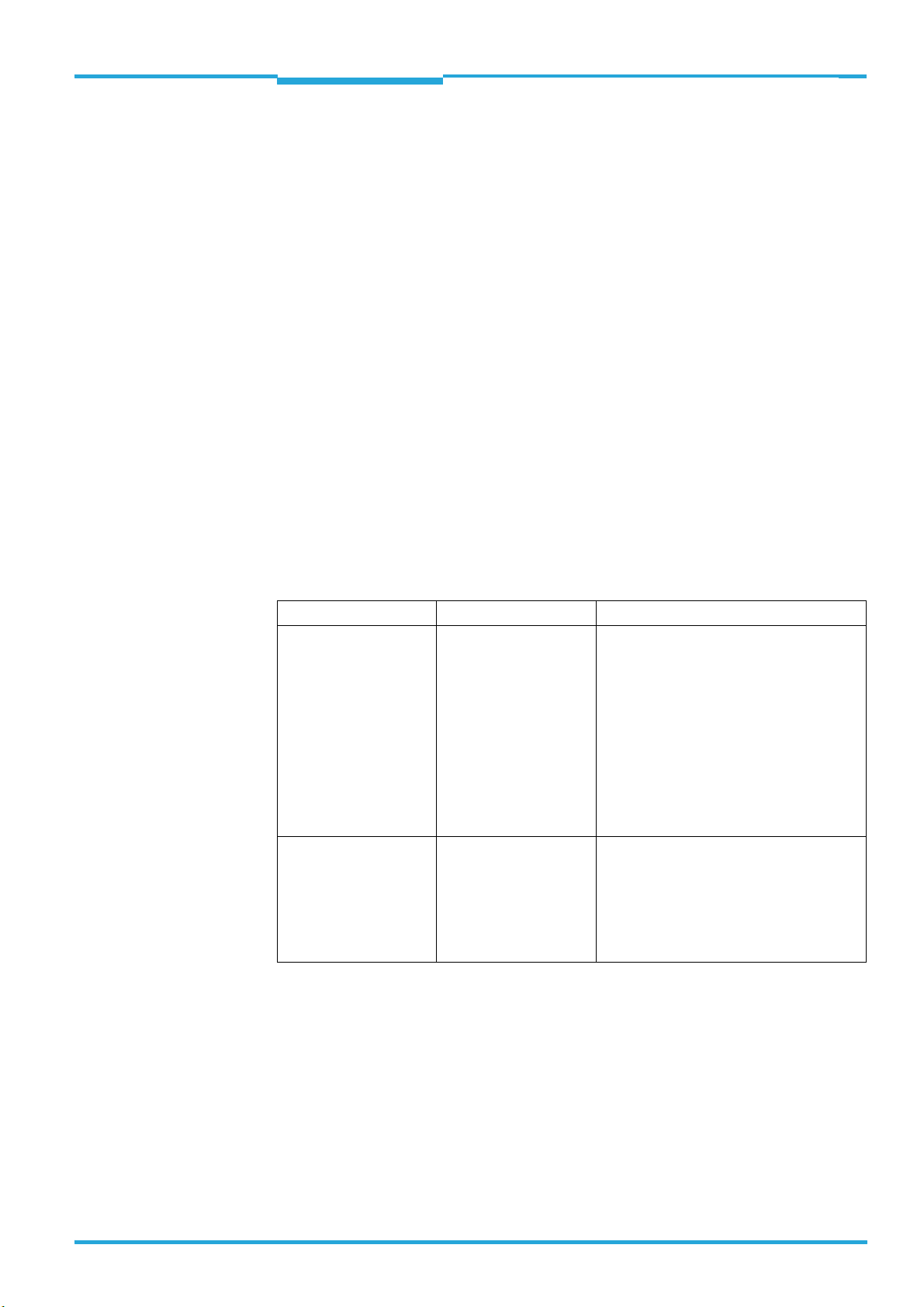
The document applies for all standard variants of the RFU63x in the following two version
series (see also type plate):
Version serie Devcie type Region assignment
RFU630-131xx:
With integrated antenna
RFU630-041xx:
Without integrated
antenna
RFU630-13100
RFU630-13101
RFU630-13102
RFU630-13103
RFU630-13104
RFU630-13105
RFU630-13106/-13107
RFU630-13108
RFU630-13110
RFU630-13111
RFU630-13112
RFU630-13113
RFU630-04100
RFU630-04101
RFU630-04102
RFU630-04105
RFU630-04106
RFU630-04108
RFU630-04109
Europe/Saudi Arabia/South Africa
USA/Canada/Mexico
Australia
India
Brazil
China
Japan
Russia/Belarus
Korea
New Zealand Indonesia
Indonesia
Taiwan
Europa/South Africa
USA/Canada
Australia
China
Japan
Russia
Singapur
In the following the different standard variants of the RFU63x RFID write/read device (UHF)
in both version series are referred to i n simplified form as "RFU630", excep t where a distinc tion of the variants is necessary.
The specified material numbers (no.) for components are used as part numbers for the SICK
ordering system.
1.2 Target group
This document is intended for qualified and technical staff, authorized for mounting and
electrical installation.
8014335/YUO7/2016-04-04 © SICK AG · Germany · All rights reserved · Subject to change without notice 5
Page 6
Chapter 1 Technical Information
WARNING
About this document
RFU63x RFID Write/Read Device (UHF)
1.3 Further sources for obtaining information
"RFUI630-131xx RFID write/read device (UHF)“ Quickstart, no. 8016526
"RFUI630-041xx RFID write/read device (UHF)“ Quickstart, no. 8015215
Notes on intended use, scope of delivery, mounting and electrical installation in principle,
commissioning, configuration with SOPAS ET, maintenance, transport and storage as well
as on repair is included in the RFU63x quickstart.
Internet Product page of RFU630
www.sick.com/RFU63x
For type-depending, detailed technical data see online data sheets (PDF)
Dimensional drawings and 3D CAD dimension models in various electronic formats
Range diagram for the internal antenna (PDF) for RFU630-131xx
EC Declarations of Conformity (PDF)
Overview and description of the command strings (on demand)
SOPAS ET configuration software with online help function
RFID Product information with an overview of the accessories (PDF), no. 8016267 (Eng-
lish version) and no. 8016266 (German version)
RFU63x opera t ing i nst ructi ons of both ve rsion serie s (PDF ), i n Engl ish or Germa n , oth e r
languages if applicable
RFU63x technical information (PDF), no. 8014335 (English version), no. 8014334
(German version)
Support is also available from your sales partner in the web at www.sick.com/worldwide.
1.4 Symbols used
Some information in this document is highlighted as follows to facilitate quick access to this
information.
Risk of injury or risk of damage!
A warning refers to specific or potential dangers to the physical safety of the user. It is there
to protect the user against accidents.
The safety mark next to the warning, on the left, refers to the type of accident risk, e.g. electricity-related. The ascending warning levels (CAUTION, WARNING, DANGER) refer to the severity of the possible danger.
Always read the warnings carefully and make sure you comply with them.
1.4.1 Further markings
Important! This important note is there to advise you on special aspects.
DATA PROCESSING This type of script denotes a term in the user interface of the SOPAS ET configuration soft-
ware.
This symbol refers to supplementary technical documentation.
6 © SICK AG · Germany · All rights reserved · Subject to change without notice 8014335/YUO7/2016-04-04
Page 7
Technical Information Chapter 2
DANGER
WARNING
CAUTION
NOTICE
RFU63x
Safety information
2 Safety information
2.1 General notes
This chapter is about the safety of commissioning personnel, as well as operators of the
system in which the RFU630 is integrated.
Read the RFU63x quickstart carefully (printed version delivered with device) before
starting any work on the RFU630 in order to familiarize yourself with the device and its
functions. No. 8016526 is needed for RFU630-131xx version serie respectively no.
8015215 for the RFU630-041xx version serie.
The printed quickstart is considered a part of the device and must be kept in an accessible location in the immediate vicinity of the RFU630 at all times!
Read additionally the notes on mounting and the electrical installation in this technical
information as supplement to the quickstart.
Opening the housing of the RFU630 will invalidate any warranty claims against SICK
AG. For further warranty provisions, see the General Terms and Conditions of SICK AG,
e.g., on the delivery note of the RFU630.
Repair work on the RFU630 may only be performed by qualified and authorized service
personnel from SICK AG
2.2 Categories of safety notes
Risk of injury!
The combination of symbol and signal word indicates a situation of imminent danger, which
will lead to a fatality or serious injuries if not prevented.
Risk of injury!
T
he combination of symbol and signal word indicates a potentially dangerous situation,
which may lead to a fatality or serious injuries if not prevented.
Risk of injury!
The combination of symbol and signal word indicates a potentially dangerous situation,
which may lead to minor/slight injuries if not prevented.
Risk of damage!
A note indicates a potential risk of damage or impair on the functionality of the RFU63x RFID
write/read device or other connected devices.
8014335/YUO7/2016-04-04 © SICK AG · Germany · All rights reserved · Subject to change without notice 7
Page 8
Chapter 2 Technical Information
CAUTION
CAUTION
Safety information
RFU63x RFID Write/Read Device (UHF)
2.3 Warning note for electromagnetic radiation
RFU630-131xx
Health hazard due to high-frequency electromagnetic radiation!
The RFU630-13100 (region: Europe) is designed for operation in accordance with ETSI EN
302208. During operation with the integrated antenna and/or one or serverals externals
antenna(e), the human exposure regulations covered by EN 50364 must be observed.
In order to limit human exposure to electromagnetic fields, suitable safety distances
must be maintained during both short-term and long-term work in the radiation range
antenna(e).
Minimum distances to be maintained between the antenna and the human body during
long-term transmission:
30 cm with a max. radiation power of the antenna of 2 W ERP as per ETSI,
15 cm with a reduced radiation power of 1 W ERP,
10 cm with a radiation power of 0.5 W ERP.
The RFU630-13101 (region: USA/Canada/Mexico) satisfies the limit values of the FCC for
exposure to radiation in an uncontrolled environment.
During operation with the integrated antenna and/or one oder serverals externals an-
tenna(e), a safety distance of at least 20 cm must be maintained between the antenna
and the human body.
RFU630-041xx
Health hazard due to high-frequency electromagnetic radiation!
The RFU630-04100 (region: Europe) is designed for operation in accordance with ETSI EN
302208. During operation with the external RFA630-x00 antenna(e), the human exposure
regulations covered by EN 50364 must be observed.
In order to limit human exposure to electromagnetic fields, suitable safety distances
must be maintained during both short-term and long-term work in the radiation range
of the antenna(e).
Minimum distances to be maintained between the antenna and the human body:
30 cm with a max. radiation power of the antenna of 2 W ERP as per ETSI,
15 cm with a reduced radiation power of 1 W ERP,
10 cm with a radiation power of 0.5 W ERP.
The RFU630-04101 (region: USA/Canada/Mexico) satisfies the limit values of the FCC for
exposure to radiation in an uncontrolled environment.
During operation with the external RFA630-x01 antenna(e), a safety distance of at
least 20 cm must be maintained between the antenna and the human body.
8 © SICK AG · Germany · All rights reserved · Subject to change without notice 8014335/YUO7/2016-04-04
Page 9

Technical Information Chapter 3
RFU63x
Mounting
3 Mounting
3.1 Notes on mounting
RFU630-13101 UL-certified: Install the device only inside of buildings. The device is not
suitable for outdoor use.
The RFU630 should be attached as free from shock and vibration as possible.
If the external antenna or the RFU630 with an internal antenna is mounted in front of
the front metal surfaces, observe an angle of approx. 10°.
Use one of the optional SICK mounting sets 1 to 4, also in combination if required
depending on the application. For mounting samples, regarding the RFU630-131xx version serie, see the following pages.
8014335/YUO7/2016-04-04 © SICK AG · Germany · All rights reserved · Subject to change without notice 9
Page 10
Chapter 3 Technical Information
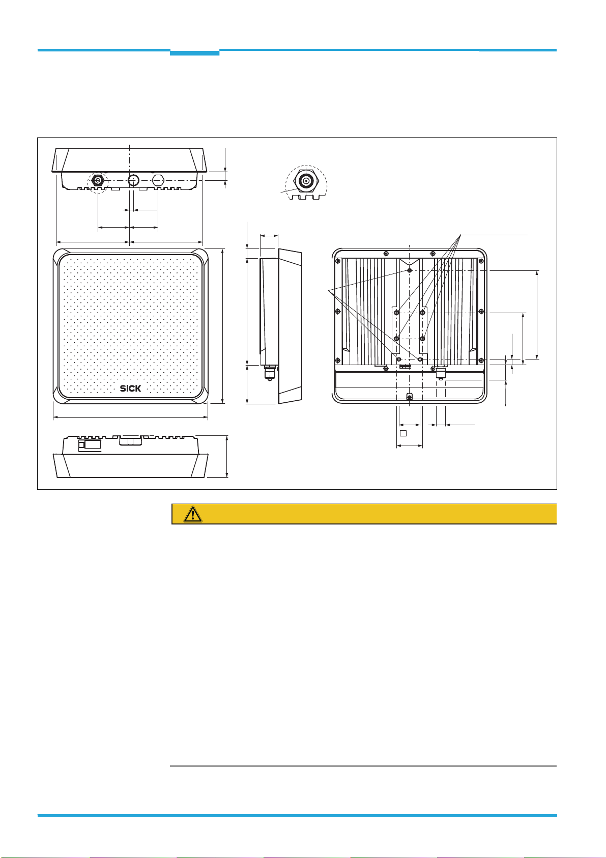
20
24
240
239
227
136.8
16
4
M6
Mounting plate 1 (for mounting to walls)
All dimensions in mm
30
227
198
61.2
0
7
218.6
32.5
53.5
240
136.8
16.4
5
7.5
M5
(12.5)
Ø
12
Ø
6.6
Ø 6
.6
Ø 5.5
M5
M6
RFU630-131xx
Hexagon screw
10 mm width
across flat
3 mm width
across flat
10 mm width across flat
Hexagon socket
3 mm width
across flat
Mounting
RFU63x RFID Write/Read Device (UHF)
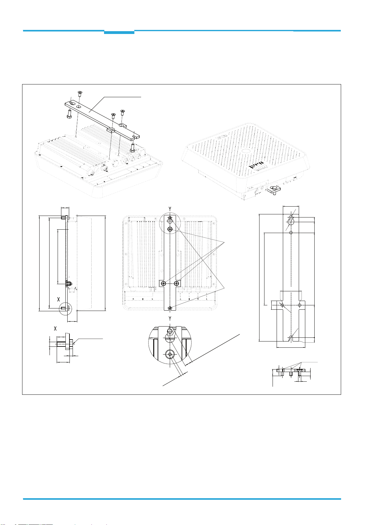
3.2 Optional mounting accessories
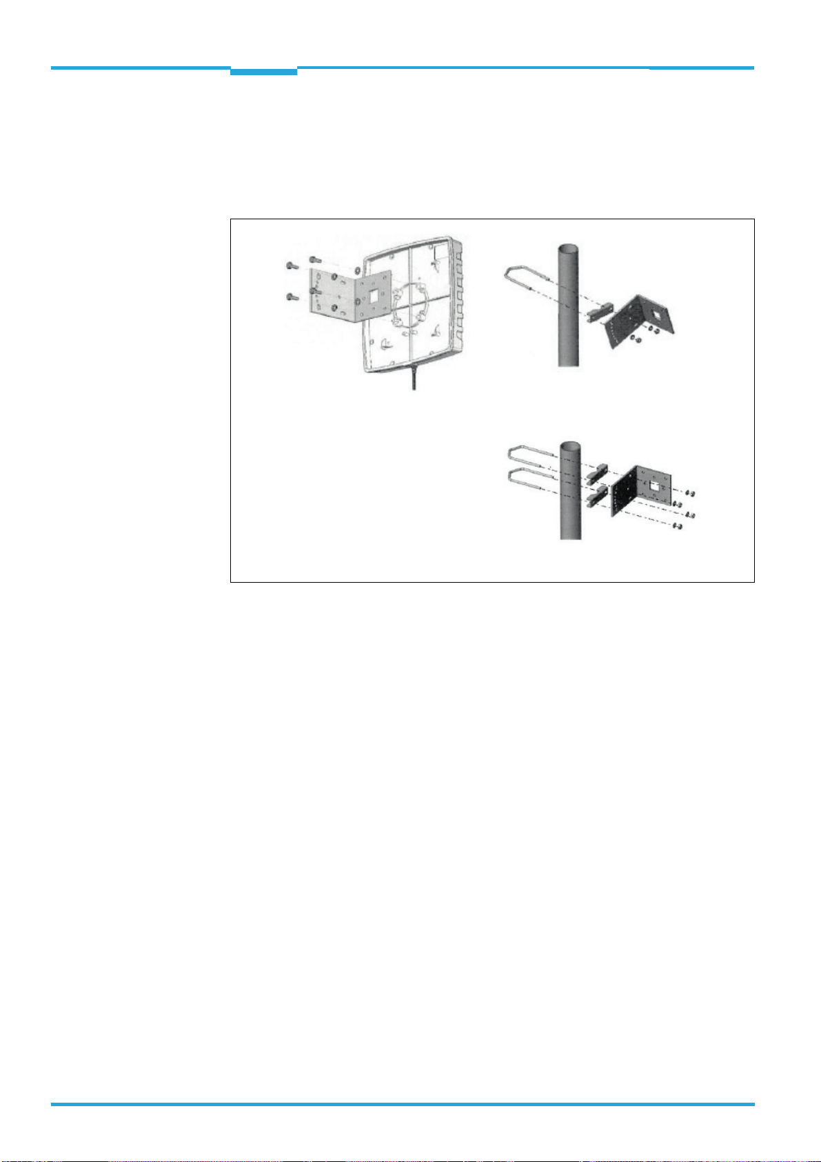
3.2.1 Installing wall mounting plate (no. 2060912) on the RFU630
10 © SICK AG · Germany · All rights reserved · Subject to change without notice 8014335/YUO7/2016-04-04
Procedure for attachment on the RFU630:
1. Either cut two M6 threads or install two bore holes with 6.5 mm through the assem-
bly base provided by the customer with a spacing of 227 mm.
2. For the time being,fasten two supplied M6 x 16 mm screws in the assembly base such
that the thread protrudes at least 8 mm up to the base of the screw head.
3. Install the mounting plate on the rear side of the RFU630 using the three supplied
M5 x 12 mm screws.
4. Attach the RFU630 together with the mounting plate onto the two protruding M6
screws and tighten them.
Page 11
Technical Information Chapter 3
110
100
57
(40)
100
57
(40)
110
Presentation without screws
A - A
A
A
M6M4
6
M6
10.6
4 x Hexagon socket
kant 4 mm width across flat
Threaded mounting
hole M4 (4 x)
Threaded mounting
hole M6 (4 x)
All dimensions in mm
Threaded mounting hole
M6, 12 mm deep
Threaded mounting hole M6
for link clamp no. 2068919
(mounting grid 57 mm x 57 mm)
VESA adapter plate for Interrogators RFU63x
and RFU62x as well as for RFA630-x0x antenna
RFU630-131xx
M6 x 16, Hexagon socket
4 mm width across flat
Mounting
RFU63x
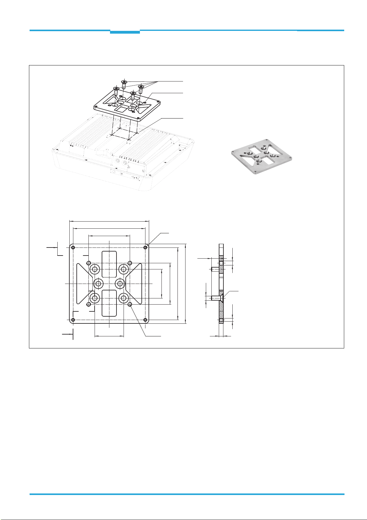
3.2.2 Installing VESA adapter plate (no. 2061688) on the RFU630
Procedure for attachment on the RFU630:
1. Install the adapter plate on the rear side of the RFU630 using the four supplied
M6 x 16 mm screws.
2. Affix the RFU630 and adapter plate to the VESA bracket using four M4 screws, or to a
standard industrial bracket with a 57 mm x 57 mm grid using four M6 screws.
The screw length depends on the wall thickness of the front end of the VESA bracket.
Take care to ensure that the screwed in screws do not damage the housing of the
RFU630.
8014335/YUO7/2016-04-04 © SICK AG · Germany · All rights reserved · Subject to change without notice 11
Page 12
Chapter 3 Technical Information
All length measures in mm
Threaded mounting hole
M6, 11 mm deep
M6 x 12 mm,
self-locking
(4 x)
M6 x 16 mm
(6 x)
Mounting bracket
Angle
flange
Pivot mounting
bracket,
complete
95.2
M6
5
5
9.4
9.4
102.8
Ø 10Ø 18
80
90°
Ø 41.5
68
68
90°
60
84
30
RFU630-131xx
Mounting
RFU63x RFID Write/Read Device (UHF)
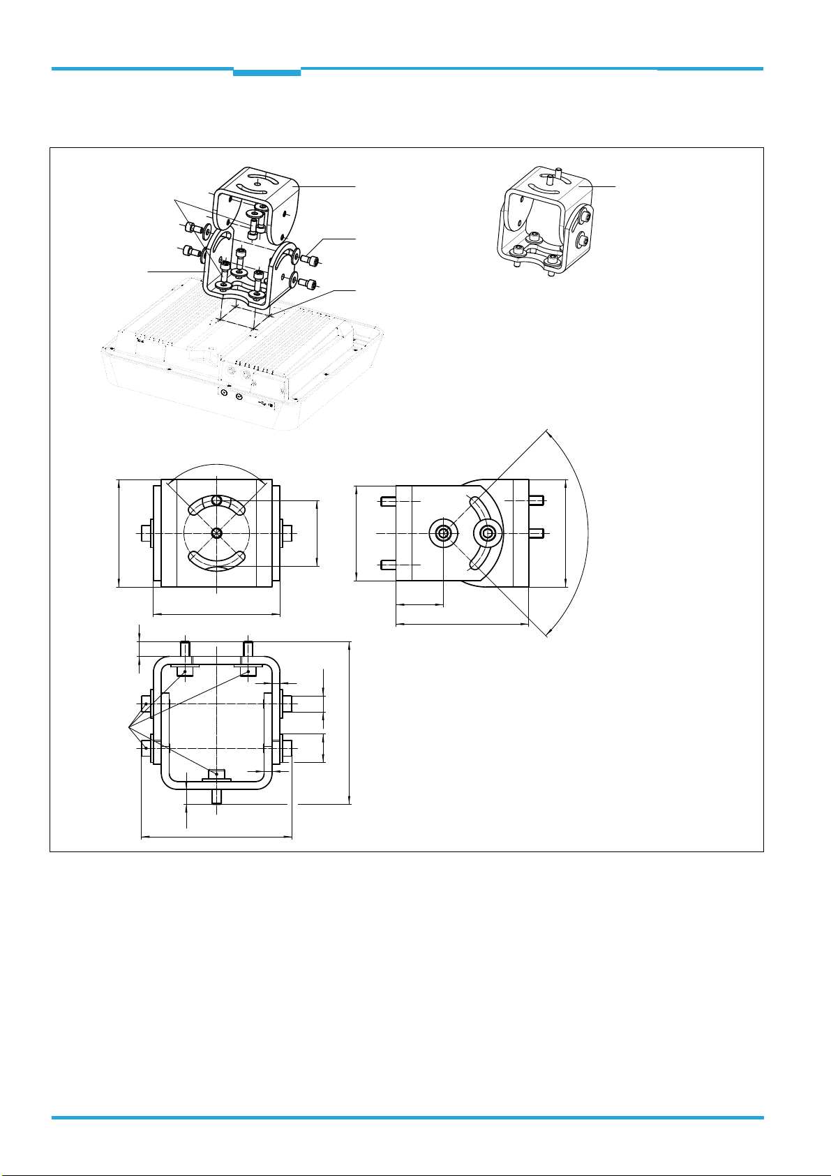
3.2.3 Installing pivot mounting bracket (no. 2061737) on the RFU630
Procedure for attachment on the RFU630:
1. Fasten the angle flange to the RFU630 (supplied are: 4x M6 x 16 mm screws with
A6 washer).
2. Fasten the mounting bracket to the assembly base provided by the customer (supplied
are: 2 x M6 x 16 mm screws with A6 washer). Do not tighten the screws just yet.
3. Fasten the RFU630 together with the mounting bracket to the angle flange (supplied
ar e: 4x self -lock ing M6 x 1 2 mm s crews and A6 washers). Do not tighten the screws just
yet.
4. Align RFU630 to the scanning point in two axes.
5. Tighten all screws.
12 © SICK AG · Germany · All rights reserved · Subject to change without notice 8014335/YUO7/2016-04-04
Page 13
Technical Information Chapter 3
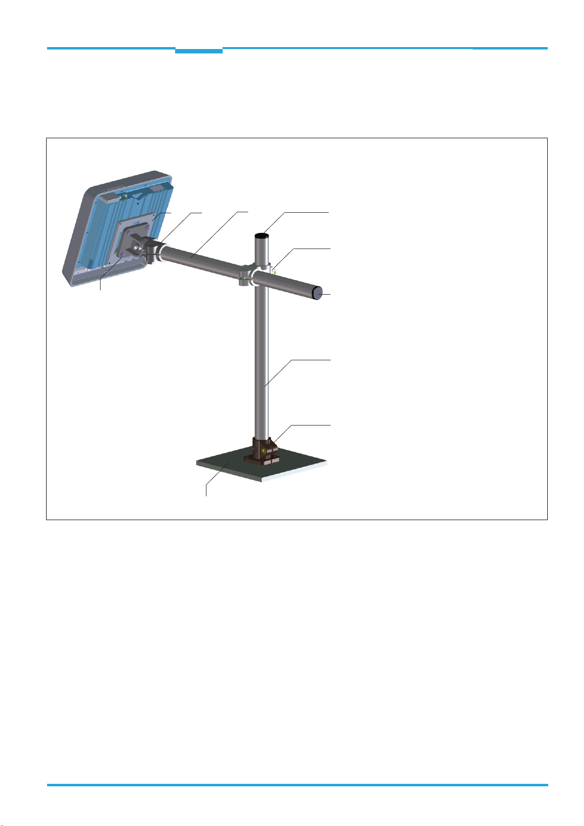
Mounting sample
1 VESA adapter plate no. 2071862,
with 2 counter-sunk screws M6 x 12,
hexagon socket (AF4)
2 Link clamp with 4 cylinder head screws
M6 x 12, no. 2068919
3 Pipe, ∅ 30 mm, length 1 m, no. 532761
4 Sealing plug, ∅ 30 mm, no. 5327613
5 Cross clamp, no. 5327612
6 Base clamp, no. 5327611
1 2
3
6
3
5
4
4
Base (e.g. plate, provided by customer)
4 x cylinder head screw
M6 x 12, hexagon socket AF4,
self-locking
RFU63x
Mounting
3.2.4 Installing a customer-specific holder for the RFU630 by using pipe elements and clamp-connections, with VESA adapter plate no. 2071862 (sample)
Part 1: Total view
8014335/YUO7/2016-04-04 © SICK AG · Germany · All rights reserved · Subject to change without notice 13
Page 14

Chapter 3 Technical Information
All dimensions in mm
Base clamp, no. 5327611
Sealing plug, ∅ 30 mm,
no. 5327613
Cross clamp, no. 5327612
Link clamp no. 2068919,
with 4 cylinder head screws M6 x 12
Pipe, ∅ 30 mm,
length 1 m,
no. 5327610
A
B
C
D
E
30.1
30.1
33
40
40
K
L
P
R
S
73
99
33
78
M8 x 25
A
B
D
G
H
30.1
6.5
40
60
40
K
L
M
N
O
42
50
60
8
42
P
R
S
U
33
29
M8 x 25
45
A
B
C
D
E
G
H
K
L
M
N
O
S
T
30.1
6.5
45
40
40
75
33
57
106
73
7
7 5
M8 x 35
M8 x 35
Mounting
Part 2: Dimensional drawings of components
RFU63x RFID Write/Read Device (UHF)
14 © SICK AG · Germany · All rights reserved · Subject to change without notice 8014335/YUO7/2016-04-04
Page 15

Technical Information Chapter 3
RFU63x
Mounting
3.3 Mounting the CDB650-204 or CDM420-0006 connection module
The mounting location for the connection module (distance to RFU630) depends on the
physical design (RS-232) and the transmission rate used of the serial data interface AUX 1.
Recommended cable length between RFU630 and connection module:
Max. 3 m with fixed data transmission 57.6 kBd.
For detailed information on mounting and the electrical installation, see:
"CDB650-204 connection module" operating instructions (no. 8016155, German +
English version) e.g. as PDF in the web via www.mysick.com/CDB
"CDM420-0006 connection module" operating instructions (no. 8014808, German +
English version) e.g. as PDF in the web via www.mysick.com/CDM
The documents are also supplied in printed form with the relating connection module.
8014335/YUO7/2016-04-04 © SICK AG · Germany · All rights reserved · Subject to change without notice 15
Page 16
Chapter 3 Technical Information
CAUTION
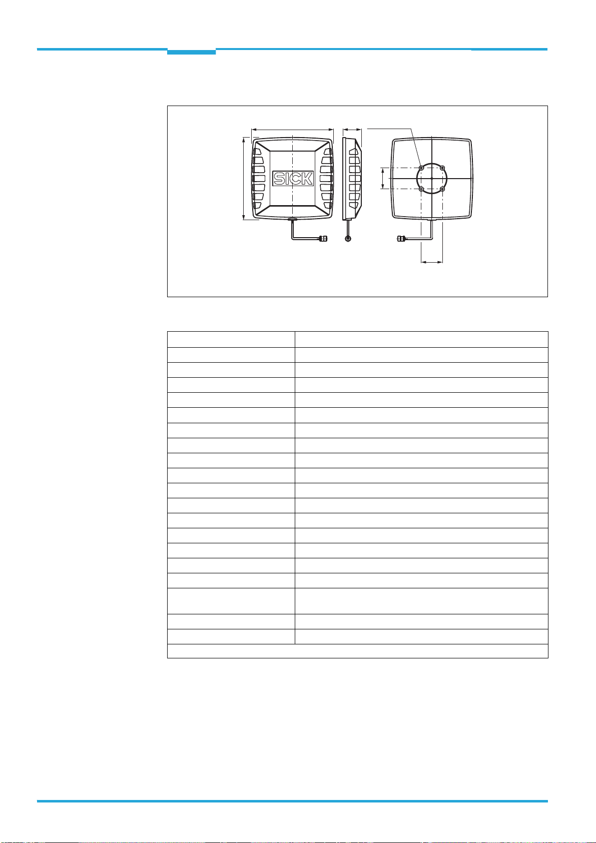
113.1 (4.45)
48.4
(1.91)
6.5
(0.26)
44.4
(1.75)
113.1 (4.45)
12.9
(0.51)
238.6 (9.39)
238.6 (9.39)
X
X
64.3
(2.53)
15.1
(0.59)
28
(1.10)
164.4 (6.47)
59.5
(2.34)
32.5
(1.28)
40
(1.57)
Ø 14.5
(0.57)
23.5
(0.93)
8.2
(0.32)
80 (3.15)
136.8 (5.39)
3
1
2
Alle Angaben in mm (inch)
All dimensions in mm (inch)
1
Sacklochgewinde M5, 8 tief
Tapped blind hole M5, 8 (0.31) deep
2
Sacklochgewinde M6, 11 tief
Tapped blind hole M6, 11 (0.43) deep
3
Elektrischer Anschluss (TNC, reverse)
Electrical connection (TNC, reverse)
Mounting
RFU63x RFID Write/Read Device (UHF)
3.4 Mounting optionals UHF antennas
3.4.1 RFA630-000/-001 antenna
Health hazard due to high-frequency electromagnetic radiation!
The RFA630-000 antenna (region: Europe) is designed for operation in accordance with
ETSI EN 302208. During operation, the human exposure regulations covered by EN 50364
must be observed.
In order to limit human exposure to electromagnetic fields, suitable safety distances
must be maintained during both short-term and long-term work in the radiation range
antenna(e).
Minimum distances to be maintained between the antenna and the human body during
long-term transmission:
30 cm with a max. radiation power of the antenna of 2 W ERP as per ETSI,
15 cm with a reduced radiation power of 1 W ERP,
10 cm with a radiation power of 0.5 W ERP.
The RFA630-001 antenna (region: USA/Canada/Mexico) satisfies the limit values of the
FCC for exposure to radiation in an uncontrolled environment.
During operation, a safety distance of at least 20 cm must be maintained between the
antenna and the human body.
16 © SICK AG · Germany · All rights reserved · Subject to change without notice 8014335/YUO7/2016-04-04
Page 17
Technical Information Chapter 3
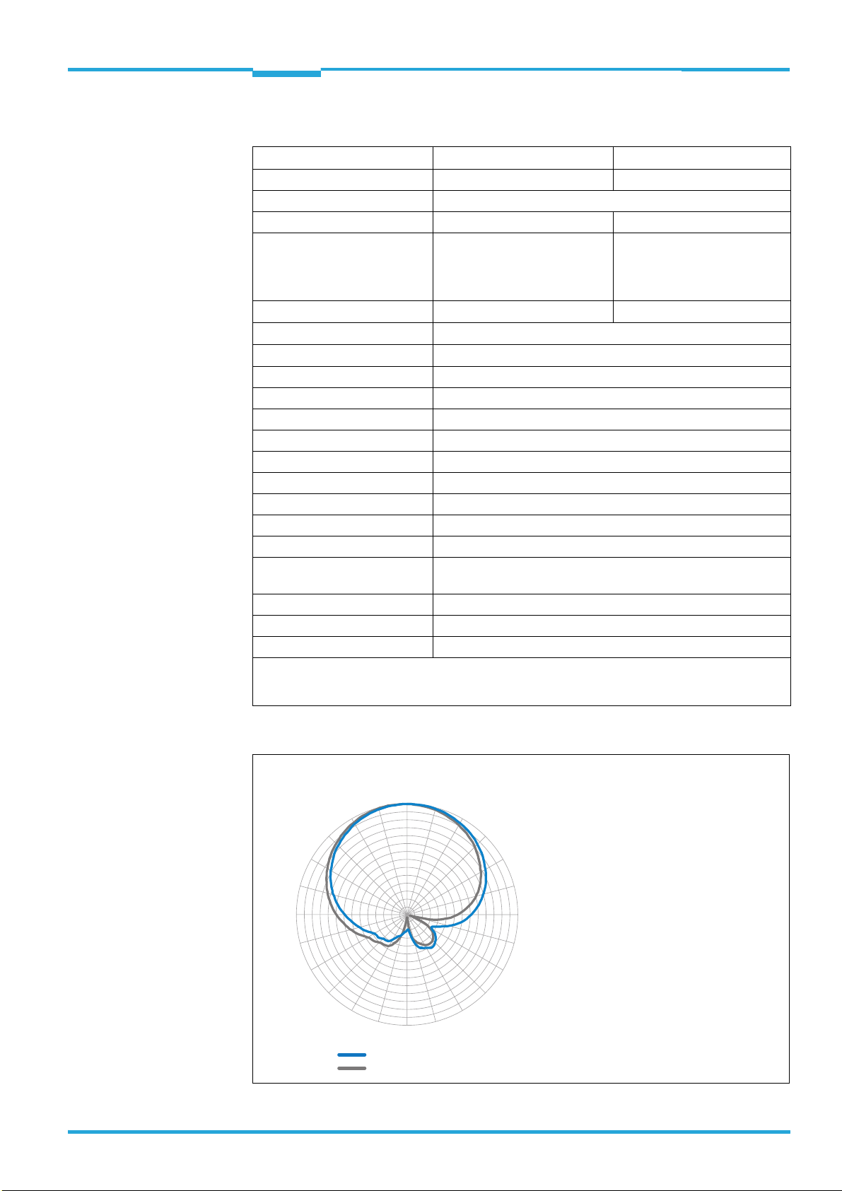
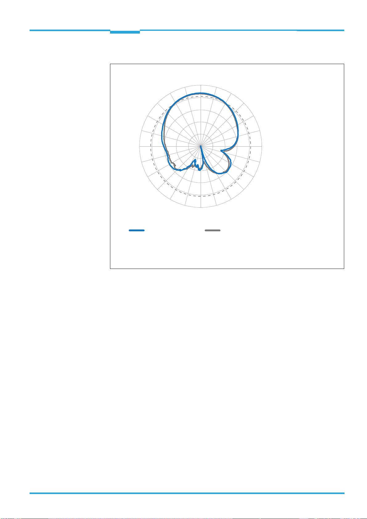
0°
15°
30°
45°
60°
75°
90°
105°
120°
135°
150°
165°
180°
–165°
–150°
–135°
–120°
–105°
–90°
–75°
–60°
–45°
–30°
–15°
–33
–30
–27
–24
–21
–18
–15
–12
–9
–6
–3
0
3
6
Elevation plane (vertical)
Azimuth plane (horizontal)
Measured gain in dBic at 866.5 MHz,
RHCP (Right-hand circular polarized)
9
Mounting
RFU63x
Technical Data
Type RFA630-000 RFA630-001
Part no. 1058383 1058384
Frequency band 860 MHz … 960 MHz
Carrier frequency 865 MHz … 868 MHz 902 MHz … 928 MHz
Permissible write/read device RFU630-13100 RFU630-13101
RFU630-13102
RFU630-13105
RFU630-13106/-13107
Maximum rated power
Polarization
4)
VSWR
Max. 2 W ERP
Circular /RHCP
Typical < 1,2
1)
3)
Max. 4 W EIRP
Gain Max. 9 dBic
Axial ratio Typical < 2 dB
3 dB aperature angle Typical 72 Grad
Front to back ratio Typical > 17 dB
Electrical connection TNC reverse, 50 Ohm
Housing (material) Aluminum, Front: polycarbonate
Enclosure rating IP 67
Weight 3 kg
Dimensions (L x W x H) 238.6 mm x 238.6 mm x 64.3 mm, see dimensional drawing
Mounting 4 x M6 threaded mounting holes (standard fixing grid
40 mm x 40 mm) or 3 M5 threaded mounting holes
Operation ambient temperature –25 °C … +50 °C
Stockage temperature –30 °C … +70 °C
Relative air humidity 5 % … 95 %, non-condensing
1) ERP = Equivalent Radiated Power. 2) EIRP = Equivalent Isotropic Radiated Power.
3) RHCP = Right-Hand Circular Polarisation.
4) VSWR = Voltage Standing Wave Ration.
2)
Radiation pattern diagram RFA630-000/-001
8014335/YUO7/2016-04-04 © SICK AG · Germany · All rights reserved · Subject to change without notice 17
Page 18

Chapter 3 Technical Information
Internet Ordering information about the antennae and theirs accessories (mountings sets and con-
Mounting
RFU63x RFID Write/Read Device (UHF)
Accessories
nection cables of different lengths) is available on the following SICK product pages on the
web:
RFA630-000: www.sick.com/1058383
RFA630-001: www.sick.com/1058384
The corresponding power loss values of the cables in the frequency band of 860 MHz to 960
MHz are also listed there.
Mounting
The housing of the RFA630-00x antenna has the same dimensions and mounting thread
holes like the RFU630 write/read device. You can use the same optional mounting accessories (brackets, plates). To do so, see Chapter 3.2 Optional mounting accessories,
Page 10.
If several antennas are used in a reading station, e.g. two on each side of a conveyor system, make sure that the antennas are not directly facing each other, but are installed at
staggered parallel positions.
18 © SICK AG · Germany · All rights reserved · Subject to change without notice 8014335/YUO7/2016-04-04
Page 19
Technical Information Chapter 3
CAUTION
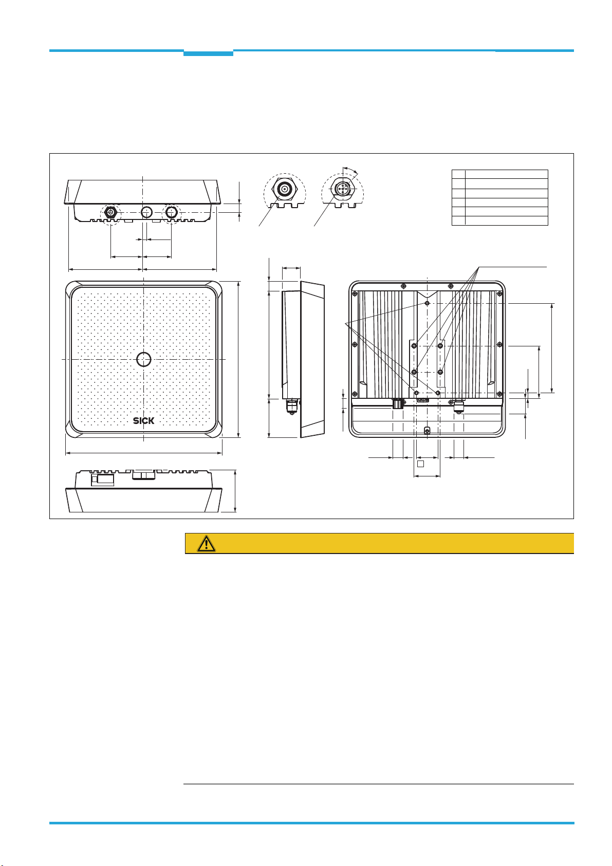
113.1 (4.45) 113.1 (4.45)
48.4
(1.91)
6.5
(0.26)
44.4
(1.75)
12.9
(0.51)
XW
238.6 (9.39)
238.6 (9.39)
64.3 (2.53)
15.5
(0.61)
15.1
(0.59)
164.4 (6.47)
28
(1.10)
59.5
(2.34)
Ø 16
(0.63)
32.5
(1.28)
Ø 14.5
(0.57)
23.5
(0.93)
8.2
(0.32)
80 (3.15)
136.8 (5.39)
1
2
40
(1.57)
X
3
W
45°
4
Alle Angaben in mm (inch)
All dimensions in mm (inch)
1
Sacklochgewinde M5, 8 tief
Tapped blind hole M5, 8 (0.31) deep
2
Sacklochgewinde M6, 11 tief
Tapped blind hole M6, 11 (0.43) deep
Pin Leuchtfarbe / light color
1 LED: blau/blue
2 LED: grün/green
3 GND
4 LED: rot/red
5 N.C.
Ue / Vin = DC 10 V ... 30 V
I
e
/ Iin = max. 10 mA
3
TNC, reverse
4
5-pol. M12Stecker,
A-codiert
5-pin M12
male
connector,
A-coded
Mounting
RFU63x
3.4.2 RFA630-100/-101 antenna
As special feature of this antenna a process feedback LED on the front plate center can be
powered externally for controlling the displayed RGB color to signalizise an event in the
reading process.
Health hazard due to high-frequency electromagnetic radiation!
The RFA630-100 antenna (region: Europe) is designed for operation in accordance with
ETSI EN 302208. During operation, the human exposure regulations covered by EN 50364
must be observed.
In order to limit human exposure to electromagnetic fields, suitable safety distances
must be maintained during both short-term and long-term work in the radiation range
antenna(e). Minimum distances to be maintained between the antenna and the human
body during long-term transmission:
30 cm with a max. radiation power of the antenna of 2 W ERP as per ETSI,
15 cm with a reduced radiation power of 1 W ERP,
10 cm with a radiation power of 0.5 W ERP.
The RFA630-101 antenna (region: USA/Canada/Mexico) satisfies the limit values of the
FCC for exposure to radiation in an uncontrolled environment.
During operation, a safety distance of at least 20 cm must be maintained between the
antenna and the human body.
8014335/YUO7/2016-04-04 © SICK AG · Germany · All rights reserved · Subject to change without notice 19
Page 20
Chapter 3 Technical Information
Mounting
RFU63x RFID Write/Read Device (UHF)
Technical Data
Type RFA630-100 RFA630-101
Part no. 1059946 1059947
Frequency band 860 MHz … 960 MHz
Carrier frequency 865 MHz … 868 MHz 902 MHz … 928 MHz
Permissible write/read device RFU630-13100 RFU630-13101
RFU630-13102
RFU630-13105
RFU630-13106/-13107
Maximum radiated power
Polarizsation
4)
VSWR
Max. 2 W ERP
Circular /RHCP
Typical < 1,2
1)
3)
Max. 4 W EIRP
Gain Max. 9 dBic
Axial ratio Typical < 2 dB
3 dB aperture angle Typical 72 Grad
Front to back ratio Typical > 17 dB
Electrical connection - TNC reverse, 50 Ohm
- 5-pin M12 male connector, A-coded for process feedback LED
Housing (material) Aluminum, front: polycarbonate
Enclosure rating IP 67
Weight 3 kg
Dimensions (L x W x H) 238.6 mm x 238.6 mm x 64.3 mm, see dimensional drawing
Mounting 4 x M6 threaded mounting holes (standard fixing grid
40 mm x 40 mm) or 3 M5 threaded mounting holes
Ambient temperature Operation: –25 °C … +50 °C, Stockage: –30 °C … +70 °C
Relative air humidity 5 % … 95 %, non-condensing
1) ERP = Equivalent Radiated Power. 2) EIRP = Equivalent Isotropic Radiated Power.
3) RHCP = Right-Hand Circular Polarisation.
4) VSWR = Voltage Standing Wave Ration
2)
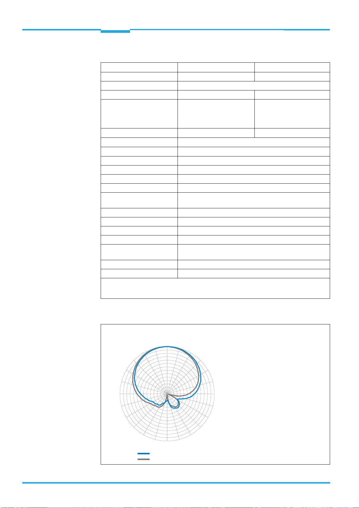
Radiation pattern diagram RFA630-100/-101
Measured gain in dBic at 866.5 MHz,
RHCP (Right-hand circular polarized)
0°
9
6
3
0
–3
–6
–9
180°
15°
30°
45°
60°
75°
90°
105°
120°
135°
150°
165°
–75°
–90°
–105°
–120°
–60°
–45°
–135°
–30°
–150°
–15°
–12
–15
–18
–21
–24
–27
–30
–33
–165°
Azimuth plane (horizontal)
Elevation plane (vertical)
20 © SICK AG · Germany · All rights reserved · Subject to change without notice 8014335/YUO7/2016-04-04
Page 21

Technical Information Chapter 3
RFU63x
Mounting
Accessories
Internet Ordering information about the antennae and theirs accessories (mountings sets and con-
nection cables of different lengths) is available on the following SICK product pages on the
web:
RFA630-100: www.sick.com/1059946
RFA630-101: www.sick.com/1059947
The corresponding power loss values of the cables in the frequency band of 860 MHz to 960
MHz are also listed there.
Mounting
The housing of the RFA630-10x antenna has the same dimensions and mounting thread
holes like the RFU630 write/read device. You can use the same optional mounting accessories (brackets, plates). To do so, see Chapter 3.2 Optional mounting accessories,
Page 10 .
If several antennas are used in a reading station, e.g. two on each side of a conveyor system, make sure that the antennas are not directly facing each other, but are installed at
staggered parallel positions.
8014335/YUO7/2016-04-04 © SICK AG · Germany · All rights reserved · Subject to change without notice 21
Page 22
Chapter 3 Technical Information
253
254.5
56.5
65
65
4 x M6 x 10
2
1
All dimensions in mm
1 N female connector
2 Threaded mounting holes (4 x)
Mounting
RFU63x RFID Write/Read Device (UHF)
3.4.3 RFA641-3440 antenna
Technical Data
Type RFA641-3440
Part no. 6034316
Frequency range 860 MHz … 960 MHz (for Europe and USA)
Maximum radiated power 10 W
Polarization Circular
*)
VSWR
Gain 7 dBi ± 1 dBi
Axial ratio < 1dB
3 dB aperture angle
Front to back ratio
Electrical connection Cable 0.3 m with N female connector
Impedance 50 Ohm
Housing (material) ABS
Enclosure rating IP 54 accord. to EN 60529/A1
Weight Approx. 470 g
Dimension (L x B x H) 254.5 mm x 253 mm x 56.5 mm, see dimensional drawing
Mounting 4 x M6 threaded mounting holes, 10 mm deep
Operation ambient
temperature
Stockage temperature –20 °C ... +70 °C
Relative air humidity 5 % … 95 %, non-condensing
*) VSWR = Voltage Standing Wave Ration.
< 1.3 : 1
–20 °C ... +70 °C
22 © SICK AG · Germany · All rights reserved · Subject to change without notice 8014335/YUO7/2016-04-04
Page 23
Technical Information Chapter 3
–30
–20
–10
0
10
Measured gain in dBi at 900 MHz
0°
15°
30°
45°
60°
75°
90°
105°
120°
135°
150°
165°
180°
–165°
–150°
–135°
–120°
–105°
–90°
–75°
–60°
–45°
–30°
–15°
horizontal – vertical vertical – vertical
–3 dB at +33°
–3 dB at –34°
Aperature angle 67°
(main radiation
direction)
–3 dB at +34°
–3 dB at –35°
Aperature angle 69°
(main radiation
direction)
3 dB
Mounting
RFU63x
Radiation pattern diagram RFA641-3440
Internet Ordering information about the antenna and its accessories (mounting bracket and adapter
Accessories
cables [N male connector / TNC reverse] of different lengths) is available on the following
SICK product pages on the web:
www.sick.com/6034316
The corresponding power loss values of the cables in the frequency band of 860 MHz to 960
MHz are also listed there.
Mounting
If several antennas are used in a reading station, e.g. two on each side of a conveyor system, make sure that the antennas are not directly facing each other, but are installed at
staggered parallel positions.
Fixed wall-mounting (alignment not adjustable):
1. Mark and drill four fixing holes in the installation surface in accordance with the dimensional drawing.
2. When installing on a plate or frame, insert the supplied bolts from the rear through the
installation surface and tighten the antenna.
Installation to a tube (alignment adjustable in two axis):
Use the mounting bracket no. 5321692.
1. Tight the bracket to the antenna (step 1).
8014335/YUO7/2016-04-04 © SICK AG · Germany · All rights reserved · Subject to change without notice 23
Page 24
Chapter 3 Technical Information
Step 1
Step 2a
Step 2b
Mounting
RFU63x RFID Write/Read Device (UHF)
2. Use a retainer and a bushing to install the bracket to the tube (step 2a).
Due to the combination of the retainer on the tube and the curved arranged drill holes
at the der leading edge of the bracket, the antenna can adjust in two axis to the objects.
If mounting across to the axis of the tube is sufficient, both retainers can also be used
for stable installation (step 2b).
24 © SICK AG · Germany · All rights reserved · Subject to change without notice 8014335/YUO7/2016-04-04
Page 25

Technical Information Chapter 3
RFU63x
Mounting
3.4.4 RFA651-5731 antenna
66
66
190
14
30
17.7
M5
1
14
1 Threaded pins (4 x)
2 N female connector
Technical Data
Type
Part no. 6036102
Frequency band 865 MHz ... 870 MHz (Europe)
Permissible write/read device RFU630-13100
Maximum radiated power
Polarization Linear
*)
VSWR
Gain Max. 8 dBic
Axial ratio
3 dB aperture angle
Front to back ratio
Electrical connection N female connector, 50 Ohm
Housing (material) Plastic (PP)
Enclosure rating IP 67 accord. to EN 60529: 1991-10; A1: 2002-02
Weight Approx. 0.8 kg
Dimensions (L x W x H) 190 mm x 190 mm x 30 mm, see dimensional drawing
Mounting 4 x Befestigungsgewindestange M5 x 17.7 mm
Ambient temperature
(operation/stockage)
Relative air humidity 5 % ... 95 %, non-condensing
*) VSWR = Voltage Standing Wave Ration
RFA651-5731
Typical < 1.3
–45°C ... +70 °C
190
38
20.2
All dimensions in mm
2
8014335/YUO7/2016-04-04 © SICK AG · Germany · All rights reserved · Subject to change without notice 25
Page 26

Chapter 3 Technical Information
a
Internet Ordering information about the antenna and its accessories (mounting bracket and adapter
Mounting
RFU63x RFID Write/Read Device (UHF)
Accessories
cables [N male connector / TNC reverse] of different lengths) is available on the following
SICK product pages on the web:
www.sick.com/6036102
The corresponding power loss values of the cables in the frequency band of 865 MHz to 870
MHz are also listed there.
Mounting
If several antennas are used in a reading station, e.g. two on each side of a conveyor system, make sure that the antennas are not directly facing each other, but are installed at
staggered parallel positions.
Wall-mounting (alignment adjustable in two axis):
Use the mounting bracket no. 5322196.
1. For the foot of the bracket, mark and drill four fixing holes on the wall in accordance
with the dimensional drawing in the enclosed mounting instructions.
2. Install the cruciformed mounting plate of the adjusting arm to the antenna
3. Connect the cable to the antenna.
4. Fix the foot of the bracket on the wall using the enclosed bolts.
5. Align the antenna with the help of both hinges to the objects.
26 © SICK AG · Germany · All rights reserved · Subject to change without notice 8014335/YUO7/2016-04-04
Page 27

Technical Information Chapter 4
RFU63x
Electrical installation
4 Electrical installation
4.1 Notes on the electrical installation
The electrical installation must only be performed by electrically qualified persons.
Standard safety requirements must be met when working in electrical systems.
Electrical connections between the RFU630 and other devices may only be connected
or disconnected when the system is not live, otherwise the devices may be damaged.
The permissible ambient temperature range for this work is 0 °C to +50 °C.
RFU630-13101 (UL-certified):
– UL certified only if UL logo is printed on type plate.
– Install the device only inside of buildings. The device is not suitable for outdoor use.
– Lead the connection cables to the external device interfaces only inside of buildings.
– Use a supply voltage according to SELV (EN 60950-1:2006-04) and LPS (EN 60950-
1:2006-04) or Class 2 (UL 1310).
Operation of the RFU630 below 0 °C:
For information on configuring the electrical installation when using the RFU630-101xx
at temperatures down to –25 °C, see Chapter 4.5, Page 39.
When using connecting or extension cables with an open e nd, ma ke sur e that bare w ire
ends are not touching (risk of short-circuit when the supply voltage is switched on).
Take appropriate measures to isolate the wires.
Customer-specific provided cables:
Wire cross sections of the supply cable from the customer's power system as well of
data and switching signal cables should be designed in accordance with the applicable
standards.
All circuits connected to the RFU630 must be designed as SELV circuits. The power sup-
ply or power supply unit must satisfy the requirements of SELV in accordance with the
currently applicable EN 60950-1. (SELV = Safety Extra Low Voltage.)
Do not switch on the supply voltage for the RFU630 respectively the CDB650-204 or
CDM420-0006 connection module until the connection work has been completed and
the wiring work has been tested thoroughly.
Prerequisites for enclosure rating IP 65
The cover for the USB female connector and Micro SD card slot has to be screwed onto
the housing during normal operation.
Protect the RFU63x from moisture and dust when the cover is open.
The electrical connections not used have to be fitted with protective caps or plugs.
The same also applies for the EMC requirements (ESD) according to CE.
Cable lengths
The possible length of cable between RFU630 and the host computer depends on the
selected physical design of the host interface and the set data transmission rate. For the
serial interfaces, see Chapter 4.7.3 Wiring the data interface, Page 47.
8014335/YUO7/2016-04-04 © SICK AG · Germany · All rights reserved · Subject to change without notice 27
Page 28

Chapter 4 Technical Information
e.g. cable no. 2055419 (2 m)
e.g. cable no. 6049780 (2 m)
CDB650-204
SerialSerial
SerialSerial
e.g. cable
no. 6034414 (2 m)
e.g. cable
no. 6036106 (2 m)
Configuration
Diagnostics
SOPASSOPAS
“Power/Serial Data/CAN/I/O”
(AUX 1, HOST 1)
No. 1064114
...
...
1
2
DC 18 V ... 30 V
GND
PC
e.g. cable no. 2014054 (2 m)
“Serial RS-232” (AUX 1), alternatively to Ethernet AUX port
“Ethernet” (AUX 2)
DC 18 V ... 30 V
1)
“USB” (AUX 3),
alternatively to Ethernet AUX port
External antennae (optional)
2)
...
13
2) e.g. RFA630-000 for region Europe1) Required minimum input voltage depends on the cable
length between CDB650-204 and RFU630-131xx,
see RFU63x-131xx operating instructions (no. 8016526)
EthernetEthernet
USBUSB
RFU630-
131xx
“Ethernet” (HOST 2)
Input 2
(e.g. encoder)
Input 1
(e.g. external reading trigger)
Output 1
(e.g. indicator lamp)
Output 2
RFU630-
131xx
e.g. cable no. 2055419 (2 m)
e.g. cable no. 6049780 (2 m)
“Serial RS-232/RS-422/485” (HOST 1), alternatively to Ethernet HOST port
CDB650-204
SerialSerial
e.g. cable
no. 6034414 (2 m)
“Power/Serial Data/CAN/I/O”
(AUX 1, HOST 1)
No. 1064114
...
...
1
2
DC 18 V ... 30 V
GND
HOST
Furt her d ata
processing
DC 18 V ... 30 V
1)
Inputs/Outputs = digital
Additional external inputs/outputs via
parameter cloning module CMC600
External antennae (optional)
2)
...
13
Reading result
2) e.g. RFA630-000 for region Europe1) Required minimum input voltage depends on the cable
length between CDB650-204 and RFU630-131xx,
see RFU63x-131xx operating instructions (no. 8016526)
EthernetEthernet
Electrical installation
RFU63x RFID Write/Read Device (UHF)
4.2 Overview of all interfaces and connection options
4.2.1 RFU630-131xx with integrated antenna
Configuration and diagnostics
28 © SICK AG · Germany · All rights reserved · Subject to change without notice 8014335/YUO7/2016-04-04
Reading mode
Page 29

Technical Information Chapter 4
CDB650-204
SerialSerial
e.g. cable
no. 6034414 (2 m)
Configuration
Diagnostics
SOPASSOPAS
No. 1064114
...
...
1
2
DC 18 V ... 30 V
GND
PC
e.g. cable no. 2014054 (2 m)
“Serial RS-232” (AUX 1), alternatively to Ethernet AUX port
“Ethernet” (AUX 2)
DC 18 V ... 30 V
1)
“USB” (AUX 3),
alternatively to Ethernet AUX port
...
14
RFU630041xx
SerialSerial
EthernetEthernet
USBUSB
1) Required minimum input voltage depends on the cable
length between CDB650-204 and RFU630-041xx,
see RFU630-041xx operating instructions (no. 8015215)
e.g. cable no. 2055419 (2 m)
e.g. cable no. 6049780 (2 m)
“Power/Serial Data/CAN/I/O”
(AUX 1, HOST 1)
External antennae (optional)
2)
2) e.g. RFA630-000 for region Europe
e.g. cable
no. 6036106 (2 m)
Electrical installation
RFU63x
4.2.2 RFU630-041xx without integrated antenna
Configuration and diagnostics
Reading mode
1
2
GND
DC 18 V ... 30 V
DC 18 V ... 30 V
Input 1
(e.g. external reading trigger)
Input 2
(e.g. encoder)
Output 1
(e.g. indicator lamp)
Output 2
Additional external inputs/outputs via
parameter cloning module CMC600
Inputs/Outputs = digital
1)
CDB650-204
No. 1064114
...
...
“Serial RS-232/RS-422/485” (HOST 1), alternatively to Ethernet HOST port
SerialSerial
External antennae (optional)
...
14
e.g. cable no. 6049780 (2 m)
“Power/Serial Data/CAN/I/O”
(AUX 1, HOST 1)
e.g. cable no. 2055419 (2 m)
length between CDB650-204 and RFU630-041xx,
see RFU63x-041xx operating instructions (no. 8015215)
2)
no. 6034414 (2 m)
e.g. cable
RFU630041xx
“Ethernet” (HOST 2)
Reading result
2) e.g. RFA630-000 for region Europe1) Required minimum input voltage depends on the cable
EthernetEthernet
HOST
Furt her d ata
processing
8014335/YUO7/2016-04-04 © SICK AG · Germany · All rights reserved · Subject to change without notice 29
Page 30

Chapter 4 Technical Information
RFU630
Aux 1
RS-232
CAN
SOPAS ET
Configuration
Software
HOST
Further data
processing
Host 1
PC/HOST
RS-232
1)
RS-422
1)
RS-485
1)
1) Select one of the three options
2) Recommended on high data volume
◂ Configuration/Data output ▸
Aux 3
USB
◂ Configuration
◂ Configuration/Data output ▸
Ethernet
Aux 2 ◂ Configuration/Data output ▸
Host 2 ◂ Configuration/Data output
2)
▸
Electrical installation
RFU63x RFID Write/Read Device (UHF)
4.2.3 Using the data interfaces
Possible interface HOST 1 AUX 1 HOST 2 AUX 2 AUX 3
Assignable function
Read result output (format 1)
Read result output (format 2)
Read diagnosis output (fixed format)
Observation of HOST interface traffic
Configuration (SOPAS ET, commands)
= Output of the same function simultaneously possible via the interfaces
= Access only makes practical sense via one of the interfaces (risk of collision)
RS-232/-
RS-232 Ethernet Ethernet USB
422/485
Important! Only one of several selectable functions can be allocated to each interface.
The logical AUX interface of the RFU630 can operate the serial data interface, USB interface
and Aux port of the Ethernet interface in parallel.
In a similar manner, the logical HOST interface of the RFU630 can operate the serial data
interface and the Host port of the Ethernet interface in parallel. The physical RS-232 and
RS-422/485 Host interfaces cannot be used simultaneously.
However, the data released by means of a command string is only output on the interface
on which the request was received.
For output in real time, one of the two ports of the Ethernet interface must be selected.
30 © SICK AG · Germany · All rights reserved · Subject to change without notice 8014335/YUO7/2016-04-04
Page 31

Technical Information Chapter 4
“Power/Serial Data/CAN/I/0” connection Adapter cable M12 to D-Sub,
e.g. no. 2055419 (2 m)
CAN L
CAN H
TD+ (RS-422/485), HOST
TD– (RS-422/485),
TxD (RS-232), HOST
DC 18 V ... 30 V
TxD (RS-232), AUX
RxD (RS-232), AUX
RD+ (RS-422/485), HOST
GND
RD– (RS-422/485),
RxD (RS-232), HOST
Result 1 (switching output 1)
N.c.
N.c.
Result 2 (switching output 2)
7
6
Sensor 2 (switching input 2)
Sensor 1 (switching input 1)
SensGND
4
3
2
1
5
8
9
10
11
12
13
14
15
16
17
RFU630-131xx
Male connector, M12,
17-pin, A-coded
CAN L
CAN H
TD+ (RS-422/485), HOST
TD– (RS-422/485),
TxD (RS-232), HOST
DC 18 V ... 30 V
TxD (RS-232), AUX
RxD (RS-232), AUX
RD+ (RS-422/485), HOST
GND
RD– (RS-422/485),
RxD (RS-232), HOST
Result 1 (switching output 1)
Result 2 (switching output 2)
7
6
Sensor 2 (switching input 2)
Sensor 1 (switching input 1)
SensGND
4
3
2
1
5
8
9
10
11
12
13
14
15
Male connector,
D-Sub HD, 15-pin
4
3
2
1
TD+
TD–
RD+
RD–
“Ethernet” connection
RFU630-131xx
Female
connector,
M12, 4-pin,
D-coded
6
1
10
5
11
15
3
1
7
2
6
5
4
8
13
14
17
15
9
10
12
16
11
1
43
2
Electrical installation
RFU63x
4.3 M12 male and female connector pin assignments on the RFU630
8014335/YUO7/2016-04-04 © SICK AG · Germany · All rights reserved · Subject to change without notice 31
Page 32

Chapter 4 Technical Information
Electrical installation
RFU63x RFID Write/Read Device (UHF)
4.4 Pin assignments and lead color assignments of cables
4.4.1 RFU63x ("Power/SerialData/CAN/I/0" connection) to CDB650-204
Connection cable 1:1: no. 6052286 (2 m), no. 6051194 (3 m), no. 6051195 (5 m)
Ambient temperature range:
Stationary installation: –40 °C to +80°C, mobile installation: –25 °C to +80°C
Supply voltage: DC 18 V ... 30 V
4.4.2 RFU630 ("Power/SerialData/CAN/I/0" connection) to CDM420-0006
a) Adapter cable no. 2056184 (0.35 m), no. 2049764 (0.9 m), no. 2055419 (2 m),
no. 2055420 (3 m), no. 2055859 (5 m)
b) Adapter cable, suitable for drag chain use, no. 2061480 (2 m), no. 2061605 (3 m),
no. 2061481 (5 m)
Ambient temperature range:
Stationary installation: –40 °C to +80°C, mobile installation: –25 °C to +80°C
Supply voltage: DC 18 V ... 30 V
12
3
2
13
1
11
10
16
9
4
5
14
6
17
7
8
15
Female connector,
M12, 17-pin, A-coded
(front view)
Illustration may differ
6
11
Male connector,
D-Sub HD, 15-pin
(front view)
10
5
1
15
Pin Signal Function Pin
2 DC 18 V ... 30 V Supply voltage 1
8 RxD (RS-232), AUX Aux interface (receiver) 2
7 TxD (RS-232), Aux Aux interface (sender) 3
15 Sensor 2 Switching input 2 4
1GND Ground 5
11 RD+ (RS-422/485), Host Host interface (receiver+) 6
12 RD– (RS-422/485)/
Host interface (receiver–) 7
RxD (RS-232), Host
5 TD+ (RS-422/485), Host Host interface (sender+) 8
6 TD– (RS-422/485)/
Host interface (sender–) 9
TxD (RS-232), Host
4 CAN H CAN bus (IN/OUT) 10
3 CAN L CAN bus (IN/OUT) 11
13 Result 1 Switching output 1 12
14 Result 2 Switching output 2 13
10 Sensor 1 Switching input 1 14
9 SensGND Common ground for all inputs 15
16 N.c. – –
17 N.c. – –
32 © SICK AG · Germany · All rights reserved · Subject to change without notice 8014335/YUO7/2016-04-04
Page 33

Technical Information Chapter 4
Female connector,
M12, 17-pin, A-coded
(front view)
...
Illustration may differ
3
1
7
2
6
5
4
8
13
14
17
15
9
10
12
16
11
Electrical installation
RFU63x
4.4.3 RFU630 ("Power/AUX/CAN/I/0" connection) to customer-specific connection unit (power supply unit or switching cabinet)
a) Adapter cable no. 6042772 (3 m), no. 6042773 (5 m), no. 6048817 (10 m)
Ambient temperature range:
Stationary installation: –40 °C to +80°C, mobile installation: –5 °C to +80°C
Supply voltage: DC 18 V ... 30 V, has to be protected by fuse 2 A
Pin Signal Function Color of lead
1 GND Ground Brown
2
DC 18 V ... 30 V
3 CAN L CAN-Bus (IN/OUT) White
4 CAN H CAN-Bus (IN/OUT) Green
5 TD+ (RS-422/485), Host Host interface (sender+) Pink
6 TD– (RS-422/485)/
TxD (RS-232), Host
7 TxD (RS-232), Aux Aux interface (sender) Black
8 RxD (RS-232), Aux Aux interface (receiver) Gray
9 SensGND Common ground for all inputs Red
10 Sensor 1 Switching input 1 Purple
11 RD+ (RS-422/485), Host Host interface (receiver+) Gray-pink
12 RD– (RS-422/485)/
RxD (RS-232), Host
13 Result 1 Switching output 1 White-green
14 Result 2 Switching output 2 Brown-green
15 Sensor 2 Switching input 2 White-yellow
16 N.c. – Yellow-brown
17 N.c. – White-gray
Supply voltage Blue
Host interface (sender–) Yellow
Host interface (receiver–) Red-blue
8014335/YUO7/2016-04-04 © SICK AG · Germany · All rights reserved · Subject to change without notice 33
Page 34

Chapter 4 Technical Information
Electrical installation
RFU63x RFID Write/Read Device (UHF)
b) Adapter cable, suitable for drag chain use, ECOLAB, no. 2070425 (3 m), no. 2070426
(5 m), no. 2070427 (10 m)
Ambient temperature range:
Stationary installation: –40 °C to +80°C, mobile installation: –25 °C to +80°C
Supply voltage: DC 18 V ... 30 V, has to be protected by fuse 2 A
12
3
2
13
1
11
10
16
9
Female connector,
M12, 17-pin, A-coded
(front view)
Pin Signal Function Color of lead
1GND Ground Blue
2
3 CAN L CAN-Bus (IN/OUT) Green
4 CAN H CAN-Bus (IN/OUT) White
5 TD+ (RS-422/485), Host Host interface (sender+) Pink
6 TD– (RS-422/485)/
7 TxD (RS-232), Aux Aux interface (sender) Black
8 RxD (RS-232), Aux Aux interface (receiver) Gray
9 SensGND Common ground for all inputs White-black
10 Sensor 1 Switching input 1 Purple
11 RD+ (RS-422/485), Host Host interface (receiver+) Gray-pink
12 RD– (RS-422/485)/
13 Result 1 Switching output 1 White-green
14 Result 2 Switching output 2 Brown-green
15 Sensor 2 Switching input 2 White-yellow
16 N.c. – Yellow-brown
17 N.c. – White-gray
4
5
14
6
17
7
8
15
DC 18 V ... 30 V
TxD (RS-232), Host
RxD (RS-232), Host
...
Illustration may differ
Supply voltage Brown
Host interface (sender–) Yellow
Host interface (receiver–) Red-blue
34 © SICK AG · Germany · All rights reserved · Subject to change without notice 8014335/YUO7/2016-04-04
Page 35

Technical Information Chapter 4
Electrical installation
RFU63x
c) Adapter cable, suitable for drag chain use, no. 6045141 (5 m)
Ambient temperature range:
Stationary installation: –40 °C to +85°C, mobile installation: –25 °C to +80°C
Supply voltage: DC 18 V ... 30 V, has to be protected by fuse 2 A
12
3
2
13
1
11
10
16
9
Female connector,
M12, 17-pin, A-coded
(front view)
Pin Signal Function Color of lead
1GND Ground Gray
2
3 CAN L CAN-Bus (IN/OUT) Gray-pink
4 CAN H CAN-Bus (IN/OUT) Purple
5 TD+ (RS-422/485), Host Host interface (sender+) Red
6 TD– (RS-422/485)/
7 TxD (RS-232), Aux Aux interface (sender) Green
8 RxD (RS-232), Aux Aux interface (receiver) Brown
9 SensGND Common ground for all inputs White-yellow
10 Sensor 1 Switching input 1 Brown-green
11 RD+ (RS-422/485), Host Host interface (receiver+) Pink
12 RD– (RS-422/485)/
13 Result 1 Switching output 1 Red-blue
14 Result 2 Switching output 2 White-green
15 Sensor 2 Switching input 2 Yellow
16 N.c. – Yellow-brown
17 N.c. – White-gray
4
5
14
6
17
7
8
15
DC 18 V ... 30 V
TxD (RS-232), Host
RxD (RS-232), Host
...
Illustration may differ
Supply voltage White
Host interface (sender–) Black
Host interface (receiver–) Blue
8014335/YUO7/2016-04-04 © SICK AG · Germany · All rights reserved · Subject to change without notice 35
Page 36

Chapter 4 Technical Information
Female connector,
M12, 17-pin, A-coded
(front view)
Illustration may differ
3
1
7
2
6
5
4
8
13
14
17
15
9
10
12
16
11
Male connector, M12,
4-pin, D-coded
(front view)
Male connector,
RJ-45, 8-pin
(front view)
Illustration may differ
1
43
2
Electrical installation
RFU63x RFID Write/Read Device (UHF)
4.4.4 RFU630 ("Power/AUX/CAN/I/0" connection) to customer-specific power supply unit
Adapter cable no. 6048319 (10 m)
Ambient temperature range:
Stationary installation: –40 °C to +85°C, mobile installation: –25 °C to +80°C
Supply voltage: DC 18 V ... 30 V, has to be protected by fuse 2 A or
Supply voltage: DC 12 V ... 30 V, has to be protected by fuse 2.5 A
Pin Signal Function Color of lead
1 GND Ground Brown
2
DC 18 V (12 V) ... 30 V
Supply voltage Blue
4.4.5 RFU630 ("Ethernet" connection) to Ethernet (RJ-45) or PROFINET (RJ-45)
Ethernet cables:
a) Adapter cable no. 6034414 (2 m), no. 6044400 (3 m), no. 6034415 (5 m),
no. 6030928 (10 m), no. 6036158 (20 m)
Ambient temperature range:
Stationary installation: –20 °C to +60°C, mobile installation: –0 °C to +50°C
b) Adapter cable, suitable for drag chain use, ECOLAB no. 6050198 (2 m), no. 6050199
(3 m), no. 6050200 (5 m), no. 6050201 (10 m), no. 6050596 (20 m)
Ambient temperature range: mobile installation: –25 °C to +60°C
Pin Signal Function Pin
1 TD+ (Ethernet) Sender+ 1
3 TD– (Ethernet) Sender– 2
2 RD+ (Ethernet) Receiver+ 3
4 RD– (Ethernet) Receiver– 6
36 © SICK AG · Germany · All rights reserved · Subject to change without notice 8014335/YUO7/2016-04-04
PROFINET cables:
a) Adapter cable no. 6048244 (2 m), no. 6048245, (5 m), no. 6048246 (10 m)
b) Adapter cable with M12 male connector, angled (here not shown): no. 6048253 (2 m),
no. 6048254 (5 m), no. 6048255 (10 m)
Page 37

Technical Information Chapter 4
Male connector, M12,
4-pin, D-coded
(front view)
Male connector,
RJ-45, 8-pin
(front view)
Illustration may differ
1
43
2
Electrical installation
RFU63x
Ambient temperature range:
Stationary installation: –40 °C to +70°C, mobile installation: –20 °C to +60°C
Pin Signal Function Pin
1 TD+ (Ethernet) Sender+ 1
3 TD– (Ethernet) Sender– 2
2 RD+ (Ethernet) Receiver+ 3
4 RD– (Ethernet) Receiver– 6
4.4.6 RFU630 ("Ethernet“ connection) to PROFINET (open end)
Ethernet cables:
a) Adapter cable no. 6048247 (2 m), no. 6048248 (5 m), no. 6048249 (10 m)
Ambient temperature range:
Stationary installation: –40 °C to +70°C, mobile installation: –20 °C to +60°C
PROFINET cables:
b) Adapter cable with M12 male connector, angled (here not shown): no. 6048256 (2 m),
no. 6048257 (5 m), no. 6048258 (10 m), no. 6048259 (25 m)
Ambient temperature range:
Stationary installation: –40 °C to +70°C, mobile installation: –20 °C to +60°C
43
1
Male connector, M12,
4-pin, D-coded
(front view)
Pin Signal Function Color of lead
1 TD+ (Ethernet) Sender+ Yellow
2
3 RD+ (Ethernet) Receiver+ Orange
4RD– (Ethernet) Receiver– Blue
2
TD– (Ethernet)
Illustration may differ
Sender– White
8014335/YUO7/2016-04-04 © SICK AG · Germany · All rights reserved · Subject to change without notice 37
Page 38

Chapter 4 Technical Information
Female connector,
M12, A-coded
(front view)
Illustration may differ
1
43
5
2
Electrical installation
RFU63x RFID Write/Read Device (UHF)
4.4.7 CDB650-204 or CDM420-0006 connection module to CAN network
CAN data cable no. 6021166 (5 m)
Ambient temperature range:
Stationary installation: –40 °C to +70°C, mobile installation: –20 °C to +70°C
Pin Signal Funktion Color of lead
1– Shield –
2 DC +24 V Supply voltage Red
3GND Ground Black
4 CAN H CAN-Bus (IN/OUT) White
5 CAN L CAN-Bus (IN/OUT) Blue
4.4.8 CDB650-204 or CDM420-0006 connection module (Host interface RS-232 of RFU630) to PC
RS-232 data cable no. 2020319 (3 m)
Ambient temperature range:
Stationary installation: –30 °C to +90°C, mobile installation: –5 °C to +90°C
5
1
6
9
Female connector,
D-Sub, 9-pin
(front view)
Pin Signal Function Color of
lead
1– – – –
2 RxD (RS-232) Host interface (receiver) Brown 43 / 34 (TxD Host)
3 TxD (RS-232) Host interface (sender) Blue 44 / 35 (RxD Host)
4– – – –
5 GND Ground Black 42 / 36 (GND)
6 ... 9 – – – –
Terminal CDB650-204/
Terminal CDM420-0006
38 © SICK AG · Germany · All rights reserved · Subject to change without notice 8014335/YUO7/2016-04-04
Page 39

Technical Information Chapter 4
RFU63x
Electrical installation
4.5 Notes on the electrical installation of the RFU630 at an ambient temperature below 0 °C
The RFU630 can be operated at ambient temperatures between +50 °C and –25 °C.
4.5.1 Prerequisites
RFU630-13101 UL-certified: Install the device only inside of buildings. The device is not
suitable for outdoor use.
All other variants: For use outdoors, use suitable weather protection, which prevents
the device from heating up due to direct sunlight during the summer and protects the
device from being cooled by the wind during the winter.
Use supply voltage DC 18 V ... 30 V if:
– RFU630 is connected to the optional CDB650-204 or CDM420-0006 connection
module by a specified SICK cold-resistant cable.
– RFU630 is operated without a SICK connection module and connected with a spe-
cified SICK cold-resistant cable.
Protect the cable by a separate fuse 2 A at the start of the incoming supply circuit.
Use supply voltage DC 12 V ... 30 V if:
– RFU630 is optionally operated without a SICK connection module and connected
with the specified SICK cold-resistant cable no. 6048319 (2 x 2.5 mm
Protect the cable by a separate fuse 2.5 A at the start of the incoming supply circuit.
Use SICK standard cables for the ambient temperature range specified, also see
Chapter 4.4 Pin assignments and lead color assignments of cables, Page 32.
Only carry out connection work in ambient temperatures ranging from 0 °C to +50 °C.
The connecting cables must be fixed in place.
All cables connected to the device are locked. Yellow protective caps or plugs are
screwed onto any electrical connections that are not in use.
The RFU630 may only be operated in ambient temperatures below 0 °C when no
mounting or connection work is being carried out.
When the device is operated on the lowest limit value of the ambient temperature of
–25 °C, it must not exposed to strong air movement (e.g. inhouse due to ventilation).
2
, 10 m).
4.5.2 Behavior of the device after switch-on
Following application of the supply voltage and initialization, the RFU630 can immediately
be accessed by the SOPAS ET configuration software.
Internal temperature of housing
Below –25 °C "Ready" LED continuously flashes yellow.
–20 °C ... –25 °C "Ready" LED continuously flashes green (warm-up phase).
From –20 °C "Ready" LED permanently lights up green.
Behavior after switch-on
Device is not operational as –25 °C is below the specified minimum limit
value.
Device is not operational (communication channel still disabled) until the
internal temperature has increased to –20 °C as a result of the heat generated by the electronics.
Duration approx. 2 min.
The device has started regular operation.
Once the supply voltage has been applied, the device uses integrated temperature sensors
to measure its internal temperature. This is handled during booting.
8014335/YUO7/2016-04-04 © SICK AG · Germany · All rights reserved · Subject to change without notice 39
Page 40

Chapter 4 Technical Information
Electrical installation
RFU63x RFID Write/Read Device (UHF)
Supplement to the RFU630 operating instructions:
Status indicators on the first display level
Display LED Farbe Status
Ready
= LED flashes
Yellow Flashing, frequency 1 Hz.
Internal temperature of RFU63x below –25°C.
The device is not ready for operation
Green Flashing, frequency 1 Hz.
Internal temperature of RFU63x between –25°C and –20°C.
The device is not ready for operation.
After a warm-up phase of approx. 2 min, the RFU63x starts regular operation.RFU630.
40 © SICK AG · Germany · All rights reserved · Subject to change without notice 8014335/YUO7/2016-04-04
Page 41

Technical Information Chapter 4
DANGER
RFU630
closed current loop
with equalizing currents
via cable shield
grounding point 2
grounding point 1
grounding potential difference
PLC
Reading clock
sensor
I
U
CDB650-
204
= metal housing = plastic housing
= shielded electrical cable
RFU63x
Electrical installation
4.6 Prerequisites for the safe operation of the RFU630 in asystem
The RFU630 is designed and tested for electrical safety according to EN 60950-1: 200604/A1: 2010-03/A11: 2009-03/A12: 2011-02. It is connected to the peripheral devices
(power supply, clock reading pulse sensor(s), PLC, Host etc.) via shielded cables. The cable
shield, for example, for the data cable rests against the metal housing of the RFU630. The
device can either be grounded through the cable shield or through one of the blind hole
threads on the rear side.
If the peripheral devices have metal housings and if the cable shields also lie on their housings, it is assumed that all devices involved in the installation have the same ground poten-
tial.
This is achieved for instance by complying with the following conditions:
Mounting the devices on conductive metal surfaces
Correctly grounding the devices/metal surfaces in the system
If necessary, low-impedance and current carrying equipotential bonding between areas
with different ground potentials.
If these conditions are not met, e.g. on devices in a widely distributed system over several
buildings, potential equalization currents may, due to different ground potentials, flow along
the cable shields between the devices, which can lead to hazards.
8014335/YUO7/2016-04-04 © SICK AG · Germany · All rights reserved · Subject to change without notice 41
Risk of injury/risk of damage via electrical current!
Potential equalization currents between the RFU630 and other grounded devices in the
system can have the following effects:
Dangerous voltages on the metal housing of the RFU630, for instance
Incorrect function or irreparable damage to the devices
Damage/irreparable damage of the cable shield due to heating and cable fires
Where local conditions are unfavorable and thus do not meet conditions for a safe
earthing method (same ground potential at all grounding points), take measures in
accordance with the following explanations.
Page 42

Chapter 4 Technical Information
grounding point 1
Electro-
optical
signal
isolator
Electro-
optical
signal
isolator
PLC
Reading
clock sensor
grounding point 2
RFU630
shielded electrial cablemetal housing fiber optic cable
Electrical installation
RFU63x RFID Write/Read Device (UHF)
Remedial measures
The most common solution to prevent potential equalization currents on cable shields is to
ensure low-impedance and current carrying equipotential bonding. If this is not possible, the
following solution approaches serve as a suggestion.
Important! We expressly advise against opening up the cable shields. Doing this means that the EMC
limit values can no longer be complied with and that the safe operation of the device data
interfaces can no longer be guaranteed.
a) Measures for widely distributed system installations
On widely distributed system installations with correspondingly large potential differences,
we recommend setting up local islands and connecting them using commercially available
electro-optical signal isolators. This measure achieves a high degree of resistance to electromagnetic interference while at the same time complying with all the requirements of
EN 60950-1.
The ground loop is isolated by using the electro-optical signal isolator between the islands.
Within the islands, a stable equipotential bonding prevents equalizing currents at the cable
shields.
b) Measures for small system installations
For smaller installations with only slight potential differences, insulated installation of the
RFU630 and of peripheral devices may be a sufficient solution.
42 © SICK AG · Germany · All rights reserved · Subject to change without notice 8014335/YUO7/2016-04-04
Page 43

Technical Information Chapter 4
electrically
insulatetd
grounding point 2 grounding point 3grounding point 1
grounding potential difference
U
shielded electrial cable
PLC
Reading clock
sensor
RFU630
RFU63x
Electrical installation
Even in the event of large differences in the ground potential, ground loops are effectively
prevented, meaning that equalizing currents can no longer flow via the cable shields and
metal housing.
Important! The power supply for the RFU630 and the connected peripheral devices must also guaran-
tee the required level of insulation.
Under certain circumstances, a tangible potential can develop between the insulated metal
housings and the local ground potential.
Special national regulations for Sweden and Norway
Varning och atjarder
Utrustning som ar kopplad till skyddsjord via jordat vagguttag och/eller via annan utrustning
och samtidigt ar kopplad till kabel-TV nat kan i vissa fall medfora risk for brand.
For att undvika detta skall vid anslutning av utrustningen till kabel-TV nat galvanisk iso-
lator finnas mellan utrustningen och kabel-TV natet.
Advarsel og tiltaker
Utstyr som er koplet til beskyttelsesjord via nettplugg og/eller via annet jordtilkoplet utstyr
- og er tilkoplet et kabel - TV nett, kan forarsake brannfare.
For a unnga dette skal det ved tilkopling av utstyret til kabel-TV nettet installeres en gal-
vanisk isolator mellom utstyret og kabel-TV nettet.
Corresponding English translation
Devices which are connected to the electrical system PE of the building via a mains connection or other devices with a connection to the PE, and which are connected to a cable distribution system with coaxial cables, can under certain circumstances cause a risk of fire.
Connections to a cable distribution system must therefore be made such that electrical
insulation is offered below a certain frequency range (galvanic separating link).
8014335/YUO7/2016-04-04 © SICK AG · Germany · All rights reserved · Subject to change without notice 43
Page 44

Chapter 4 Technical Information
“DC 18 V ... 30 V”
“Sensor 2”
“Host 1” (serial)
“Aux 1” (serial)
“Result 2”
“Result 1”
“CAN”
“Sensor 2”
“Sensor 1”
“External input 2“
2)
“External input 1“
2)
“Sensor 1”
DC 18 V ... 30 V
1)
“AUX”
PLC
CAN bus
1)
PLC
“Result 1”
“Result 2”
PLC
PLC
“External output 1“
2)
“External output 2“
2)
CDB650-204/CDM420-0006
Connection module
Photo-electric
switch
Reading clock
Futher
functions
“HOST 1” (serial)
“AUX 1” (serial)
RS-232
CMC600
1) Required minimum input voltage depends on the cable length between CDB650-204 and RFU630, see RFU63x-131xx (no. 8016526) respectively
RFU63x-041xx (no. 8015215) operating instructions
2) An optional CMC600 paramenter cloning module is required to provide the additional switching inputs and outputs.
HOST/PLC
Further data
processing
PC
Configuration
Diagnosistics
2)
Write/read device
Interface
RFU630
Tra nsp onde r
Internal/external
antenna(s)
“Ethernet” (Host 2/Aux 2)
“USB” (Aux 3)
RS-232/422/485
Ethernet
USB
“Host 2”
Ethernet
“Aux 2”
“Aux 3”
Photo-electric
switch
End of
reading pulse
(alternatively)
Incremental encoder
Path increment
Electrical installation
RFU63x RFID Write/Read Device (UHF)
4.7 Installation steps
4.7.1 Block diagram: wiring the optional the CDB650-204 or CDM420-0006 connection module (overview)
The commissioning and configuration of the connection module as well as the technical
data are described in the:
"CDB650-204 connection module" operating instructions (no. 8016155, German +
English version) e.g. as PDF in the web via www.sick.com/CDB
"CDM420-0006 connection module" operating instructions (no. 8014808 German +
English version) e.g. as PDF in the web via www.sick.com/CDM
The documents are also supplied in printed form with the relating connection module.
Important! Wiring the signals without SICK Connection Module
If a customer-specific connection unit is used, the wiring in principle of the data interfaces
(serial and CAN) and switching interfaces signals can be designed according to the following
wiring diagrams for the CDM420-0006 connection module.
44 © SICK AG · Germany · All rights reserved · Subject to change without notice 8014335/YUO7/2016-04-04
Page 45

Technical Information Chapter 4
Electrical installation
RFU63x
4.7.2 Connecting up the supply voltage
The RFU630 requires a power supply unit with the following characteristics:
Supply voltage (stabilized safety extra-low voltage (SELV) according to the currently ap-
plicable standard EN 60950-1)
RFU630-13101 (UL-certified):
Use a supply voltage according to SELV (EN 60950-1:2006-04) and LPS (EN 609501:2006-04) or Class 2 (UL 1310).
Supply voltage
for RFU630
DC 18 V...30 V,
P = max. 26 W
DC 12 V...30 V,
P = max. 26 W
Connection
Cable (length) Cross-
module
CDB650-204 No. 6052286 (2 m)
No. 6051194 (3 m)
No. 6051195 (5 m)
CDM420-0006 No. 2056184 (0,35 m)
No. 2049764 (0,9 m)
No. 2055419 (2 m)
No. 2055420 (3 m)
No. 2055859 (5 m)
No. 2061480 (2 m)
No. 2061605 (3 m)
No. 2061481 (5 m)
Customerspecific connecting
No. 6042772 (3 m)
No. 6042773 (5 m)
No. 6048817 (10 m)
No. 2070425 (3 m)
No. 2070426 (5 m)
No. 2070427 (10 m)
No. 6045141 (5 m)
No. 6048319 (10 m)
No. 6048319 (10 m)
section for
supply
voltage
0.14 mm
0.14 mm
0.14 mm
0.10 mm
0.10 mm
0.10 mm
0.10 mm
0.10 mm
0.14 mm
0.14 mm2
0.14 mm
0.14 mm
0.14 mm
0.14 mm
0.14 mm
0.14 mm
0.14 mm
0.14 mm
0.25 mm
0.25 mm
Voltage drop
down on the
cable at
DC 18 V/
I
max.
2
1.0 V
2
1.5 V
2
2.3 V
2
0.2 V
2
0.5 V
2
1.0 V
2
1.5 V
2
2.5 V
2
1.0 V
1.5 V
2
2.3 V
2
1.5 V
2
2.3 V
2
4.6 V
2
1.5 V
2
2.3 V
2
4.6 V
2
2.3 V
2
2.0 V
2
3.0 V bei DC
12 V/ 1.9 A
= 1.35 A
Required minumum
supply voltage on the
connection module
DC 19.0 V
Fuse value for
protection of supply
voltage
CDB650-204 (2 A)
DC 19.5 V
DC 20.3 V
DC 18.2 V
CDM420-0006 (2 A)
DC 18.5 V
DC 19.0 V
DC 19.5 V
DC 20.5 V
DC 19.0 V
DC 19.5 V
DC 20.3 V
DC 19.5 V
DC 20.3 V
2 A at beginning of
the incoming cable
DC 22.6 V
DC 19.5 V
DC 20.3 V
DC 22.6 V
DC 20.3 V
DC 20.0 V
DC 15.0 V 2.5 A at beginning of
the incoming cable
The power source must be able to provide minimum power of 26 W respectively mini-
mum 1.5 A at DC 18 V.
If the optional CDB650-204 or CDM420-0006 connection module is used:
additional 0.5 W output power when the optional CMC600 parameter cloning module
is also used.
For suitable cable see Chapter 4.4 Pin assignments and lead color assignments of ca-
bles, Page 32.
Protection of supply cable
To ensure protection against short-circuits or overload in the supply cables from the customer's power system, the lead cross sections used have to be selected and protected
according to the national standards.
The supply voltage is fed via the connection module, please see:
Connection module interface Chapter
CDB650-204 Supply voltage
8014335/YUO7/2016-04-04 © SICK AG · Germany · All rights reserved · Subject to change without notice 45
Chapter 4.8.2 Wiring the supply voltage in the CDB650204 connection module, Page 51
Page 46

Chapter 4 Technical Information
NOTICE
Electrical installation
RFU63x RFID Write/Read Device (UHF)
Connection module interface Chapter
CDM420-0006 Supply voltage
The CDB650-204 and CDM420-0006 connection modules have each one fuse (2 A slow
blow) in the electrical circuit downstream of the S1 switch.
Wiring without SICK connection module
The connecting cable no. 6042772 (17-pin D-Sub HD female connector and open cable
end) can be used for wiring without the CDB650-204 or CDM420-0006 connection module.
The RFU63x must then be protected using a separate, slow-blow fuse (max. 2 A) at DC 18
V ... 30 V in the supplying circuit at the start of the supply cable.
Note on reverse polarity protected supply voltage for the RFU630
Risk of damage to the RFU630 due to possible short-circuit!
The supply voltage input for the RFU630 is designed with internal circuit protection to provide reverse polarity protection. The internal function ground of the RFU630 has a direct galvanic connection to the metal housing of the RFU630 due to reasons relating to high
frequency.
If the supply voltage has the incorrect polarity, this will not cause any damage provided that
the RFU630 is not connected
by either other cables
or its housing
to other peripheral devices that use the same grounding point.
Chapter 4.9.2 Wiring the supply voltage in the CDM4200006 connection module, Page 65
46 © SICK AG · Germany · All rights reserved · Subject to change without notice 8014335/YUO7/2016-04-04
Page 47

Technical Information Chapter 4
NOTICE
RFU63x
Electrical installation
4.7.3 Wiring the data interface
Wiring the Ethernet interface
1. Connect the RFU630 to the PC via an Ethernet cable (patch 1:1).
2. Set up communication via SOPAS ET configuration software.
Important! The Ethernet interface for the RFU630 has an Auto-MDIX function. This automatically
adjusts the transmission speed as well as any necessary crossover connections.
Wiring serial data interfaces
The maximum data transmission rate for the serial interface depends on the cable length
and on the type of interface. The following recommendations apply:
Type of interface Data transmission rate Distance to the target computer (Host)
RS-232 Up to 19.2 kBd
38.4 kBd ... 57.6 kBd
115.2 kBd … 500 kBd
RS-422/485
*) RS-422/485 suitable cable ant the according termination as per specification.
*)
Up to 38.4 kBd
38.4 kBd ... 57.6 kBd
57.6 kBd … 500 kBd
Max. 10 m
Max. 3 m
Max. 2 m
Max. 1.200 m
Max. 500 m
Max. 10 m
Damage to the internal interface module
If the serial data interfaces are wired incorrectly, then electronic components of the RFU630
could get damaged.
Observe the information on wiring.
Carefully check the wiring prior to switching on the RFU630.
The wiring is done using the connection module, please see:
Connection module Data interface Chapter
CDB650-204 RS-232
RS-422
RS-485
CDM420-0006 RS-232
RS-422
RS-485
Chapter 4.8.3 Wiring the RS-232 serial host data interface
in the CDB650-204 connection module, Page 52
Chapter 4.8.4 Wiring the RS-422 serial host data interface
in the CDB650-204 connection module, Page 53
Chapter 4.8.5 Wiring the RS-485 serial host data interface
in the CDB650-204 connection module, Page 54
Chapter 4.9.3 Wiring the RS-232 serial host data interface
in the CDM420-0006 connection module, Page 66
Chapter 4.9.4 Wiring the RS-422 serial host data interface
in the CDM420-0006 connection module, Page 67
Chapter 4.9.5 Wiring the RS-485 serial host data interface
in the CDM420-0006 connection module, Page 68
Recommendation Use shielded data cables (twisted pair leads).
To prevent interference factors, do not lay data cables over a longer route in parallel
with power supply cables and motor cables, in cable channels, for example.
8014335/YUO7/2016-04-04 © SICK AG · Germany · All rights reserved · Subject to change without notice 47
Page 48

Chapter 4 Technical Information
Electrical installation
RFU63x RFID Write/Read Device (UHF)
Termination of the RS-422 data interface
Termination can be implemented in the CDB650-204 or CDM420-0006 connection module. See "CDB650-204 connection module" operating instructions (no. 8016155) respectively "CDM420-0006 connection module" operating instructions (no. 8014808).
4.7.4 Wiring the CAN interface
The wiring is done using the connection module, please see:
Connection module Data interface Chapter
CDB650-204 CAN
CDM420-0006 CAN
Chapter 4.8.6 Wiring the CAN interface in the CDB650204 connection module, Page 55
Chapter 4.9.6 Wiring the CAN interface in the CDM4200006 connection module, Page 69
4.7.5 Wiring the digital switching inputs
Physical switching inputs on the RFU630
The two physical switching inputs "Sensor 1" and "Sensor 2" of the RFU630 can be used for
starting and/or ending the clock reading pulse or for feeding an incremental signal.
Expansion: Additional logical switching inputs in the RFU630 converted to physical "external“ switching inputs in the optional connection module
Thanks to the optional CMC600 parameter memory module in combination with the
CDB650-204 or CDM420-0006 connection module, the two additional switching inputs "External input 1" and "External input 2" are available on the terminals in the connection module.
Important! These two external switching inputs are not suitable for time critical applications.
The wiring of the switching inputs is done using the connection module, please see:
Connection module Switching input Chapter
CDB650-204 Sensor 1
Sensor 2
External input 1
(„Ext. In 1“)
External input 2
(„Ext. In 2“)
CDM420-0006 Sensor 1
Sensor 2
External input 1
(„Aux In 1“)
External input 2
(„Aux In 2“)
Chapter 4.8.7 Wiring the "Sensor 1" switching input in
the CDB650-204 connection module, Page 56
Chapter 4.8.8 Wiring the "Sensor 2" switching input in
the CDB650-204 connection module, Page 57
Chapter 4.8.9 Wiring the "External input 1" switching
input in the CDB650-204 connection module, Page 58
Chapter 4.8.10 Wiring the "External input 2" switching
input in the CDB650-204 connection module, Page 59
Chapter 4.9.7 Wiring the "Sensor 1" switching input in
the CDM420-0006 connection module, Page 70
Chapter 4.9.8 Wiring the "Sensor 2" switching input in
the CDM420-0006 connection module, Page 71
Chapter 4.9.9 Wiring the "External input 1" switching
input in the CDM420-0006 connection module,
Page 72
Chapter 4.9.10 Wiring the "External input 2" switching
input in the CDM420-0006 connection module,
Page 73
48 © SICK AG · Germany · All rights reserved · Subject to change without notice 8014335/YUO7/2016-04-04
Page 49

Technical Information Chapter 4
RFU63x
Electrical installation
4.7.6 Wiring the digital switching outputs
Physical switching outputs on the RFU630
The two physical switching outputs "Result 1" and "Result 2" of the RFU630 can be allocated
independently of each other with various functions for the output of events in the reading
process. If the allocated event occurs, the corresponding switching output is live after the
end of the reading clock for the selected pulse duration.
Expansion: Additional logical switching outputs in the RFU630 converted to physical "external“ switching outputs in the optional connection module
Thanks to the optional CMC600 parameter cloning module in combination with the
CDB650-204 or CDM420-0006 connection module, the two additional switching outputs
"External output 1" and "External output 2" are available on the terminals in the connection
module.
Important! These two external switching outputs are not suitable for time critical applications.
The wiring of the switching outputs is done using the connection module, please see:
Connection module Switching output Chapter
CDB650-204 Result 1
Result 2
External Output 1
(„Ext. Out 1“)
External Output 2
(„Ext. Out 2“)
CDM420-0006 Result 1
Result 2
External Output 1
(„Aux Out 1“)
External Output 2
(„Aux Out 2“)
Chapter 4.8.11 Wiring the "Result 1" switching output in
the CDB650-204 connection module, Page 60
Chapter 4.8.12 Wiring the "Result 2" switching output in
the CDB650-204 connection module, Page 61
Chapter 4.8.13 Wiring the "External output 1" switching
output in the CDB650-204 connection module, Page 62
Chapter 4.8.14 Wiring the "External output 2" switching
output in the CDB650-204 connection module, Page 63
Chapter 4.9.11 Wiring the "Result 1" switching output in
the CDM420-0006 connection module, Page 74
Chapter 4.9.12 Wiring the "Result 2" switching output in
the CDM420-0006 connection module, Page 75
Chapter 4.9.13 Wiring the "External output 1" switching
output in the CDM420-0006 connection module,
Page 76
Chapter 4.9.14 Wiring the "External output 2" switching
output in the CDM420-0006 connection module,
Page 77
Important Capacitive loads on the switching outputs have an effect on the switch-on and switch-off
behavior. The maximum capacity of 100 nF is a limit value.
8014335/YUO7/2016-04-04 © SICK AG · Germany · All rights reserved · Subject to change without notice 49
Page 50

Chapter 4 Technical Information
CDB650-204 Connection module
CMC600 parameter cloning module
(optional)
Ter m C AN
Term 485RS
SGND - GND
422 485
ONOFF
NO
YES
ONOFF
ONOFF
S2 S3
S7S6
S4
CMC
ONOFF
POWER
S1
30 31 32 33 34
CAN_H
CAN_L
T+
R+
GND
40 41 42 43 44
CAN_H
CAN_L
T‒/TxD
R‒/RxD
GND
AUX interface
5
1
9
6
U
IN
U
IN
GND
GND
Shield
Shield
Shield
Shield
1234567 8
LEDs
= an optional CMC600 parameter cloning module is required to provide the additional switching inputs and outputs.
VS = DC 18 V ... 30 V
External
sensor
for reading
trigger
(e.g. photoelectric switch)
V
S
Out
GND
Result 1
PLC
GND
Result 2
to PC
to
RFU630
Pin
2: RxD
3: TxD
5: GND
Host
TD‒
TD+
RD+
RD‒
TxD
Host
RxD
GND
GND
RS-232
RS-422
VS = DC 18 V to 30 V to terminal UIN = UIN* after fuse F and switch S1
3 A T
F
SENSOR
50 51 52 53 54
RES/
OUT 3
RES/
OUT 4
Ext. Illum.
TRL+GND
20 21 22 23 24
GND
RES/
OUT 1
RES/
OUT 2
EXT.
OUT 1
EXT.
OUT 2
10 11 12 13 14 15 16 17 18
U
IN
*
U
IN
*
SGND
SGND
SGND
EXT.
IN 1
SENS/
IN 1
SENS/
IN 2
EXT.
IN 2
RS-232
3
1
7
2
6
5
4
8
13
14
17
15
9
10
12
16
11
Female
connector,
M12, 17-pin,
A-coded
Male
connector,
D-Sub,
9-pin
Electrical installation
RFU63x RFID Write/Read Device (UHF)
4.8 Using the CDB650-204 connection module
4.8.1 Wiring overview (one switching input used)
50 © SICK AG · Germany · All rights reserved · Subject to change without notice 8014335/YUO7/2016-04-04
Page 51

Technical Information Chapter 4
RFU630
CDB650-204
VS
V
S
2
1
2
1
5
Shield
1U
IN
2 GND
UIN*
GND
S1
F
Shield
Cable 1), e.g.
no. 6052286 (2 m)
GND
.
.
.
.
.
.
.
.
.
ON
OFF
S1 : POWER
DC 18 V ... 30 V
UIN*
POWER
Switch S1:
ON:
Power supply voltage U
IN
switched to UIN* via fuse to
CDB650-204 and RFU630.
U
IN
* additionally available on terminals 11 and 14.
OFF:
CDB650-204 and RFU630 disconnected from power supply voltage.
Recommended position during all electrical installation work.
VS = DC 18 V ... 30 V to terminal UIN = UIN* after fuse F and switch S1
1) Cable:
No. 6052286 (2 m)
No. 6051194 (3 m)
No. 6051195 (5 m).
GND
M12, 17-pin, A-coded
3
1
7
2
6
5
4
8
13
14
17
15
9
10
12
16
11
3
1
7
2
6
5
4
8
13
14
17
15
9
10
12
16
11
Male
connector
Female
connector
Electrical installation
RFU63x
4.8.2 Wiring the supply voltage in the CDB650-204 connection module
8014335/YUO7/2016-04-04 © SICK AG · Germany · All rights reserved · Subject to change without notice 51
Page 52

Chapter 4 Technical Information
RFU630 CDB650-204 Host
Cable 1), e.g.
no. 6052286 (2 m)
1
.
.
.
TxD
RxD
RxD
TxD
GND
GND
GND
12
1
6
12
6
43
T
‒/TxD
44
R
‒/RxD
42
GND
6
Shield
RS-232 RS-232
422
485
S6 : RS
ON
OFF
S7: Term 485
S6
422485
1) Cable:
No. 6052286 (2 m)
No. 6051194 (3 m)
No. 6051195 (5 m).
3
1
7
2
6
5
4
8
13
14
17
15
9
10
12
16
11
3
1
7
2
6
5
4
8
13
14
17
15
9
10
12
16
11
M12, 17-pin, A-coded
Male
connector
Female
connector
Electrical installation
RFU63x RFID Write/Read Device (UHF)
4.8.3 Wiring the RS-232 serial host data interface in the CDB650-204 connection module
52 © SICK AG · Germany · All rights reserved · Subject to change without notice 8014335/YUO7/2016-04-04
Page 53

Technical Information Chapter 4
RFU630 CDB650-204 Host
()
1
.
.
.
TD+
TD‒
RD+
RD‒
RD+
RD‒
TD+
TD‒
GND
GND
GND
11
12
1
55
6
11
12
6
33
T+
43
T
‒
/TxD
34
R+
44
R
‒
/RxD
42
GND
6
Shield
RS-422 RS-422
422
485
S6 : RS
ON
OFF
S7: Term 485
S6
422
S7
OFF
120 Ω
485
S7: Term 485
Switch to ON if the RS-422 receiver
in the RFU630 has to be terminated
to improve the noise ratio of the on
the cable.
1) Cable:
No. 6052286 (2 m)
No. 6051194 (3 m)
No. 6051195 (5 m).
3
1
7
2
6
5
4
8
13
14
17
15
9
10
12
16
11
3
1
7
2
6
5
4
8
13
14
17
15
9
10
12
16
11
M12, 17-pin, A-coded
Male
connector
Female
connector
Electrical installation
RFU63x
4.8.4 Wiring the RS-422 serial host data interface in the CDB650-204 connection module
Note on using the RS-422 data interface of the RFU630
The relevant interface drivers for the RFU630 comply with the standard for RS-422 and
RS-485
Activation in the RFU630 with the SOPAS ET configuration software:
S
ERIAL HOST INTERFACE/HARDWARE/RS-422/485 4 WIRE (POINT TO POINT) device page
The connection shown above is configured for operation of the host with permanently
activated drivers (often described as "RS-422 operation"). I.e., not RS-485 bus operation.
8014335/YUO7/2016-04-04 © SICK AG · Germany · All rights reserved · Subject to change without notice 53
Page 54

Chapter 4 Technical Information
RFU630 CDB650-204
Host
1
.
.
.
TD+
TD‒
RD+
RD‒
RD+/TD+
RD‒/TD‒
RD+/TD+
to the RS-485 network:
RD‒/TD‒
GND
GND
GND
Shield
GND
11
12
1
55
6
11
12
6
33
T+
43
T‒/TxD
34
R+
44
R
‒/RxD
42
GND
6
Shield
RS-485
RS-485
485
422
S6 : RS
ON
OFF
S7: Term 485
S6
422
S7
OFF
120 Ω
485
S7: Term 485
Switch to ON if the RFU630
is on the end of RS-485 bus cable.
Cable 1), e.g.
no. 6052286 (2 m)
1) Cable:
No. 6052286 (2 m)
No. 6051194 (3 m)
No. 6051195 (5 m)
3
1
7
2
6
5
4
8
13
14
17
15
9
10
12
16
11
3
1
7
2
6
5
4
8
13
14
17
15
9
10
12
16
11
M12, 17-pin, A-coded
Male
connector
Female
connector
Electrical installation
RFU63x RFID Write/Read Device (UHF)
4.8.5 Wiring the RS-485 serial host data interface in the CDB650-204 connection module
Note on using the RS-485 data interface of the RS-485 des RFU630
The relevant interface drivers for the RFU630 comply with the standard for RS-422 and
RS-485
This operating mode is only permitted if all connected devices (RFU630 and host) use
a corresponding RS-485 protocol
Activation in the RFU630 with the SOPAS ET configuration software:
S
ERIAL HOST INTERFACE/HARDWARE/RS-485 4 WIRE (BUS) device page
This configuration is not permitted in the standard data output/protocol for the
RFU630. In case of doubt, contact SICK Service
54 © SICK AG · Germany · All rights reserved · Subject to change without notice 8014335/YUO7/2016-04-04
Page 55

Technical Information Chapter 4
HostHost
Shield
1) Connection cable 1:1:
No. 6052286 (2 m)
No. 6051194 (3 m)
No. 6051195 (5 m)
2) For connecting the RFU630
an adapter cable is required,
e.g. no. 2055419 (2 m)
30 31 32 6
30 31 32 6
30 31 32 6
33
34
43
44
6
30 31 32 6
40 41 42 7
40 41 42 7
CDB650204
CDB650204
CDB650204
RFU630
RFU630
RFU630
(Slave)
(Slave)
(Slave)
GN = 01
RFU630
(Master)
GN = 63
GN = 02
GN = 03
(max. 32 participants)
Stub
Switch
ON
OFF
S2 (TermCAN):
Switch
ON
OFF
S2 (TermCAN):
Switch
ON
OFF
S2 (TermCAN):
21 22 23 6
31 32 33 7
CDM4200006
Switch
ON
OFF
S4 (TermCAN):
CAN_H
CAN_L
Shield
GND
CAN_H
CAN_L
Shield
GND
CAN_H
CAN_L
Shield
GND
CAN_H
CAN_L
Shield
GND
CAN_H
CAN_L
Shield
GND
GND
GND
GND
RxD
TxD
TD‒
RD‒
RD+
TD+
RS-232RS-422
T‒/TxD
R‒/RxD
T+
R+
CDB650-204
42
Connection cable
1)
Connection cable
1)
Connection cable
1)
Connection cable
1)
CAN
CAN
CAN
amongst
others
CAN
amongst
others
CAN
amongst
others
CAN
amongst
others
CAN
Connection of power supplies as well as
of reading clock sensor e.g. to the
master here not shown.
Switch
ON
OFF
S2 (TermCAN):
Serial Host interface
Ethernet (Host port)
Alternative connection module
2)
:
422
485
S6 (RS):
EthernetEthernet
GN = Device number
Electrical installation
RFU63x
4.8.6 Wiring the CAN interface in the CDB650-204 connection module
8014335/YUO7/2016-04-04 © SICK AG · Germany · All rights reserved · Subject to change without notice 55
Page 56

Chapter 4 Technical Information
RFU630CDB650-204
PNP sensor
VS
V
S
V
S
GND
SensGND
3.32 K
6.64 K
Sensor 1
V
in
10
99
UIN* = DC 18 V ... 30 V
a) Sensor supplied by CDB650-204
b) Sensor connected electrically isolated/externally supplied
d) Switch connected electrically isolated/externally supplied
c) Switch supplied by CDB650-204
2
1
10
2
1
12
SGND
6
Shield
11
U
IN
*
10
Sens/In 1
Out
U
IN
*
GND
S3
e.g. photo-electric switch
CDB650-204
PNP sensor
VS
GND
Connect the switch as shown in b)
12 SGND
6 Shield
11
U
IN
*
10
Out
U
IN
*
GND
S3
e.g. photo-electric
switch
Function assignment to “Sensor 1” switching input
via SOPAS (“Sensor/Input 1”):
- Start of reading clock
- Stop of reading clock
- Increment input
- if required further functions in the future
UIN*
CDB650-204
12 SGND
6 Shield
11
U
IN
*
10
GND
S3
ON
OFF
S3 : SGND-GND
ON
OFF
S3 : SGND-GND
ON
OFF
S3 : SGND-GND
V
S ext
Ratings for “Sensor 1” switching input
Switch S3: SGND-GND
ON: GND of the sensor connected to GND of
CDB650-204/RFU630.
OFF: GND of the sensor connected to
SensGND of CDB650-204/RFU630
(electrically isolated to the CDB650 204/RFU630).
Selected reference potential valid for all
switching inputs (“Sensor 1/2” and “In 1/2”).
Shield
Cable 1), e.g.
no. 6052286 (2 m)
GND
.
.
.
Shield
Shield
Vin = max. 30 V
1) Cable:
No. 6052286 (2 m)
No. 6051194 (3 m)
No. 6051195 (5 m)
Sens/In 1
Sens/In 1
SensGND
GND
Power fed to the input the assigned function,
e.g. start of reading clock.
(default setting: logic not inverted [active high],
debouncing 10 ms)
– Optodecoupled, reverse polarity protected
– Can be wired with the PNP output of a sensor
– SensGND is the shared isolated ground of all
switching inputs
Low: V
in
≤ 2 V; Iin ≤ 0.3 mA
High: 6 V ≤ V
in
≤ 30 V;
0.7 mA ≤ I
in
≤ 5 mA
Switching
behavior
Features
Electrical
values
M12, 17-pin, A-coded
3
1
7
2
6
5
4
8
13
14
17
15
9
10
12
16
11
3
1
7
2
6
5
4
8
13
14
17
15
9
10
12
16
11
Female
connector
Male
connector
Electrical installation
RFU63x RFID Write/Read Device (UHF)
4.8.7 Wiring the "Sensor 1" switching input in the CDB650-204 connection module
56 © SICK AG · Germany · All rights reserved · Subject to change without notice 8014335/YUO7/2016-04-04
Page 57

Technical Information Chapter 4
RFU630CDB650-204
PNP sensor
V
S
V
S
V
S
GND
SensGND
3.32 K
6.64 K
Sensor 2
V
in
1515
99
UIN* = DC 18 ... 30 V
a) Sensor supplied byCDB650-204
b) Sensor connected electrically isolated/externally supplied
d) Switch connected electrically isolated/externally supplied
c) Switch supplied by CDB650-204
2
1
2
1
15
SGND
7
Shield
14
U
IN
*
Out
U
IN
*
GND
S3
e.g. photo-electric switch
CDB650-204
PNP sensor
VS
GND
Connect the switch as shown in b)
15 SGND
7 Shield
14
U
IN
*
Out
U
IN
*
GND
S3
e.g. photo-electric
switch
Function assignment to “Sensor 2” switching input
via SOPAS (“Sensor/Input 2”):
- Start of reading clock
- Stop of reading clock
- Increment input
- if required further functions in the future
UIN*
CDB650-204
15 SGND
7 Shield
14
U
IN
*
GND
S3
V
S ext
Ratings for “Sensor 2” switching input
Shield
Cable 1), e.g.
no. 6052286 (2 m)
GND
.
.
.
Shield
Shield
ON
OFF
S3 : SGND-GND
ON
OFF
S3 : SGND-GND
ON
OFF
S3 : SGND-GND
Vin = max. 30 V
1) Cable:
No. 6052286 (2 m)
No. 6051194 (3 m)
No. 6051195 (5 m)
13
Sens/In 2
13
Sens/In 2
13
Sens/In 2
SensGND
GND
Switch S3: SGND-GND
ON: GND of the sensor connected to GND of
CDB650-204/RFU630.
OFF: GND of the sensor connected to
SensGND of CDB650-204/RFU630
(electrically isolated to the CDB650 204/RFU630).
Selected reference potential valid for all
switching inputs (“Sensor 1/2” and “In 1/2”).
Power fed to the input the assigned function,
e.g. stop of reading clock.
(default setting: logic not inverted [active high],
debouncing 10 ms)
– Optodecoupled, reverse polarity protected
– Can be wired with the PNP output of a sensor
– SensGND is the shared isolated ground of all
switching inputs
Low: V
in
≤ 2 V; Iin ≤ 0.3 mA
High: 6 V ≤ V
in
≤ 30 V;
0.7 mA ≤ I
in
≤ 5 mA
Switching
behavior
Features
Electrical
values
M12, 17-pin, A-coded
3
1
7
2
6
5
4
8
13
14
17
15
9
10
12
16
11
3
1
7
2
6
5
4
8
13
14
17
15
9
10
12
16
11
Female
connector
Male
connector
Electrical installation
RFU63x
4.8.8 Wiring the "Sensor 2" switching input in the CDB650-204 connection module
8014335/YUO7/2016-04-04 © SICK AG · Germany · All rights reserved · Subject to change without notice 57
Page 58

Chapter 4 Technical Information
CDB650-204
18 SGND
8 Shield
11
U
IN
*
16
CDB650-204
PNP sensor
V
S
GND
18
SGND
8
Shield
11 UIN*
16
Out
GND
S3
e.g. photo-electric
switch
V
S ext
RFU630CDB650-204
PNP sensor
VS
GND
3.32 K
6.64 K
UIN* = DC 18 V ... 30 V Vin = max. 30 V
18
SGND
8
Shield
11
U
IN
*
16
Ext. In 1
Ext. In 1
Ext. In 1
Out
GND
S3
e.g. photo-electric switch
CMC600
UIN*
GND
S3
UIN*
CMC600
CMC600
UIN*
a) Sensor supplied by CDB650-204
b) Sensor connected electrically isolated and externally supplied
d) Switch connected electrically isolated and externally supplied
c) Switch supplied by CDB650-204
Connect the switch as shown in b)
Serial Aux
(RS-232)
ON
OFF
S3 : SGND-GND
No
YES
S4 : CMC
ON
OFF
S3 : SGND-GND
No
YES
S4 : CMC
No
YES
S4 : CMC
ON
OFF
S3 : SGND-GND
V
in
V
in
V
in
“External
input 1”
SensGND
SensGND
SensGND
Software-controlled, the CMC600 transfers the
switching status of its physical “Ext. In 1” input
automatically via the cable to the serial Aux data
interface of the RFU630.
The RFU630 converts the status internally to its
logical “External input 1”.
Ratings for “External input 1”
(“Ext. In 1” switching input)
Power fed to the input starts the
assigned function, e.g. start of reading
clock.
(default setting: logic not inverted
[active high], debouncing 10 ms)
– Optodecoupled, reverse polarity
protected
– Can be wired with the PNP output of
a sensor
– SensGND is the shared isolated
ground of all switching inputs
Low: V
in
≤ 2 V; Iin ≤ 0.3 mA
High: 6 V ≤ V
in
≤ 30 V;
0.7 mA ≤ I
in
≤ 5 mA
Switching
behavior
Features
Electrical
values
Function assignment to “External input 1” switching
input via SOPAS:
- Start of reading clock
- Stop of reading clock
- if required further functions in the future
Switch S3: SGND-GND
ON: GND of the sensor connected to GND
of CDB650-204/CMC600.
OFF: Sensor connected electrically isolated
to the CDB650-204/CMC600.
Reference potential valid for all switching
inputs (“Sensor 1/2” and “In 1/2”)
Electrical installation
RFU63x RFID Write/Read Device (UHF)
4.8.9 Wiring the "External input 1" switching input in the CDB650-204 connection module
58 © SICK AG · Germany · All rights reserved · Subject to change without notice 8014335/YUO7/2016-04-04
Page 59

Technical Information Chapter 4
CDB650-204
18 SGND
8 Shield
14
U
IN
*
17
CDB650-204
PNP sensor
VS
GND
18
SGND
8
Shield
14 UIN*
17
Out
GND
S3
e.g. photo-electric
switch
V
S ext
RFU630CDB650-204
PNP sensor
VS
GND
3.32 K
6.64 K
18
SGND
8
Shield
14
U
IN
*
17
Ext. In 2
Ext. In 2
Ext. In 2
Out
GND
S3
e.g. photo-electric switch
CMC600
UIN*
GND
S3
UIN*
CMC600
CMC600
UIN*
a) Sensor supplied by CDB650-204
b) Sensor connected electrically isolated and externally supplied
d) Switch connected electrically isolated and externally supplied
c) Switch supplied by CDB650-204
Connect the switch as shown in b)
Serial Aux
(RS-232)
ON
OFF
S3 : SGND-GND
No
YES
S4 : CMC
ON
OFF
S3 : SGND-GND
No
YES
S4 : CMC
No
YES
S4 : CMC
ON
OFF
S3 : SGND-GND
V
in
V
in
V
in
„External
input 2“
UIN* = DC 18 V ... 30 V
V
in
= max. 30 V
SensGND
SensGND
SensGND
Switch S3: SGND-GND
ON: GND of the sensor connected to GND
of CDB650-204/CMC600.
OFF: Sensor connected electrically isolated
to the CDB650-204/CMC600.
Reference potential valid for all switching
inputs (“Sensor 1/2” and “In 1/2”)
Function assignment to “External input 2” switching
input via SOPAS:
- Start of reading clock
- Stop of reading clock
- if required further functions in the future
Software-controlled, the CMC600 transfers the
switching status of its physical “Ext. In 2” input
automatically via the cable to the serial Aux data
interface of the RFU630.
The RFU630 converts the status internally to its
logical “External input 2”.
Ratings for “External input 2”
(“Ext. In 2” switching input)
Power fed to the input starts the
assigned function, e.g. stop of reading
clock.
(default setting: logic not inverted
[active high], debouncing 10 ms)
– Optodecoupled, reverse polarity
protected
– Can be wired with the PNP output of
a sensor
– SensGND is the shared isolated
ground of all switching inputs
Low: V
in
≤ 2 V; Iin ≤ 0.3 mA
High: 6 V ≤ V
in
≤ 30 V;
0.7 mA ≤ I
in
≤ 5 mA
Switching
behavior
Features
Electrical
values
RFU63x
Electrical installation
4.8.10 Wiring the "External input 2" switching input in the CDB650-204 connection module
8014335/YUO7/2016-04-04 © SICK AG · Germany · All rights reserved · Subject to change without notice 59
Page 60

Chapter 4 Technical Information
RFU630
CDB650-204
U
IN
* = DC 18 V ... 30 V
Load (e.g. PLC)
Cable 1), e.g.
no. 6052286 (2 m)
13
1
.
.
.
20
Res/Out 1
22
GND
5Shield
UIN*V
S
GND
V
out
Result 1
GND
13
1
22
Quenching circuit:
Install an
anti-surge diode
directly at the
load!
For inductive load:
1) Cable:
No. 6052286 (2 m)
No. 6051194 (3 m)
No. 6051195 (5 m)
Ratings for “Result 1” switching output
PNP switching against the supply voltage V
S
(default setting: no function,
logic: not inverted [active high])
– Short-circuit proof + temperature protected
– Galvanically not separate from V
S
0 V ≤ V
out
≤ V
S
(VS − 1.5 V) ≤ V
out
≤ VS with I
out
≤ 100 mA
Switching
behavior
Features
Electrical
values
3
1
7
2
6
5
4
8
13
14
17
15
9
10
12
16
11
3
1
7
2
6
5
4
8
13
14
17
15
9
10
12
16
11
M12, 17-pin, A-coded
Female
connector
Male
connector
Electrical installation
RFU63x RFID Write/Read Device (UHF)
4.8.11 Wiring the "Result 1" switching output in the CDB650-204 connection module
60 © SICK AG · Germany · All rights reserved · Subject to change without notice 8014335/YUO7/2016-04-04
Page 61

Technical Information Chapter 4
RFU630
CDB650-204
U
IN
* = DC 18 V ... 30 V
Load (e.g. PLC)
Cable 1), e.g.
no. 6052286 (2 m)
14
1
.
.
.
22
GND
5Shield
UIN*V
S
GND
V
out
Result 2
GND
14
1
22
Ratings for “Result 2” switching output
21
Res/Out 2
Quenching circuit:
Install an
anti-surge diode
directly at the
load!
For inductive load:
1) Cable:
No. 6052286 (2 m)
No. 6051194 (3 m)
No. 6051195 (5 m)
PNP switching against the supply voltage V
S
(default setting: no function,
logic: not inverted [active high])
– Short-circuit proof + temperature protected
– Galvanically not separate from V
S
0 V ≤ V
out
≤ V
S
(VS − 1.5 V) ≤ V
out
≤ VS with I
out
≤ 100 mA
Switching
behavior
Features
Electrical
values
3
1
7
2
6
5
4
8
13
14
17
15
9
10
12
16
11
3
1
7
2
6
5
4
8
13
14
17
15
9
10
12
16
11
M12, 17-pin, A-coded
Female
connector
Male
connector
Electrical installation
RFU63x
4.8.12 Wiring the "Result 2" switching output in the CDB650-204 connection module
8014335/YUO7/2016-04-04 © SICK AG · Germany · All rights reserved · Subject to change without notice 61
Page 62

Chapter 4 Technical Information
Load (e.g. PLC)
GND
V
out
Quenching
circuit: Install an
anti-surge diode
directly at the
load!
For inductive load:
Ratings for “External output 1”(„Ext. Out 1“) switching output
RFU630
Serial Aux
(RS-232)
CDB650-204
U
IN
* = DC 18 V ... 30 V
CMC600
UIN*
“External
output 1”
23
Ext. Out 1
22
GND
6Shield
The RFU630 indicates the switching status of its
logical “External output 1” via the serial Aux data
interface.
Software-controlled, the status is automatically
taken over by the CMC600 via the cable and
converted to the physical “Ext. Out 1” output in
the CDB650-204.
PNP switching against the supply voltage UIN*
(default setting: no function/disabled,
logic: not inverted [active high])
– Short-circuit proof + temperature protected
– Galvanically not separate from U
IN
*
0 V ≤ V
out
≤ UIN*
(U
IN
* − 1.5 V) ≤ V
out
≤ UIN* with I
out
≤ 100 mA
Switching
behavior
Features
Electrical
values
Electrical installation
RFU63x RFID Write/Read Device (UHF)
4.8.13 Wiring the "External output 1" switching output in the CDB650-204 connection module
62 © SICK AG · Germany · All rights reserved · Subject to change without notice 8014335/YUO7/2016-04-04
Page 63

Technical Information Chapter 4
Load (e.g. PLC)
GND
V
out
Ratings for “External output 2”(„Ext. Out 2“) switching output
RFU630
Serial Aux
(RS-232)
CDB650-204
U
IN
* = DC 18 V ... 30 V
CMC600
UIN*
“External
output 2“
24
22
GND
6Shield
Ext. Out 2
Quenching
circuit: Install an
anti-surge diode
directly at the
load!
For inductive load:
The RFU630 indicates the switching status of its
logical “External output 2” via the serial Aux data
interface.
Software-controlled, the status is automatically
taken over by the CMC600 via the cable and
converted to the physical “Ext. Out 2” output in
the CDB650-204.
PNP switching against the supply voltage UIN*
(default setting: no function/disabled,
logic: not inverted [active high])
– Short-circuit proof + temperature protected
– Galvanically not separate from U
IN
*
0 V ≤ V
out
≤ UIN*
(U
IN
* − 1.5 V) ≤ V
out
≤ UIN* with I
out
≤ 100 mA
Switching
behavior
Features
Electrical
values
Electrical installation
RFU63x
4.8.14 Wiring the "External output 2" switching output in the CDB650-204 connection module
8014335/YUO7/2016-04-04 © SICK AG · Germany · All rights reserved · Subject to change without notice 63
Page 64

Chapter 4 Technical Information
ON
OFF
ON
OFF
ON
OFF
CDM420-0006 Connection module
CMC600 parameter cloning module
(optional)
2 A T
S8
No CMC ->
SCANNER
AUX interface
6110 5
1115
LEDs
31 32 33 34 35 36 37 38 39 40
T‒/TxD
R‒/RxD
+24 V*
Sensor 1
Aux Out 1
GND
GND
SGND
CAN_H
CAN_L
11 12 13 14 15 16 17 18 19 20
Result 1
Result 2
Aux In 2
Aux In 1
SGND
GND
GND
SGND
internal
internal
21 22 23 24 25 26 27 28 29 30
T+
R+
+24 V*
Sensor 2
Aux Out 2
GND
GND
SGND
CAN_H
CAN_L
1234
+24 V
+24 V
GND
GND
5678
Shield
Shield
Shield
Shield
POWER
Sensor 1
Sensor 2
Result 1
Result 2
S1
POWER
ON
OFF
S2 S3 S4 S6
ON
OFF
ON
OFF
RS485
Term422
Ter mCA N
SGND - GND
to RFU630
15
69
to PC
RS-232
Pin
2: RxD
3: TxD
5: GND
Result 1
PLC
GND
Result 2
External sensor
for reading trigger
(e.g. photo-electric
switch)
V
S
Out
GND
Host
TD‒
TD+
RD+
RD‒
TxD
Host
RxD
GND
GND
RS-232RS-422
RS-485
VS to terminal +24 V = UV to terminal +24 V* after fuse F and switch S1
F
V
S
= DC 18 V ... 30 V
= an optional CMC600 parameter cloning module is required to provide the additional switching inputs and outputs.
Male
connector,
D-Sub,
9-pin
Female
connector,
D-Sub-HD,
15-pin
Electrical installation
RFU63x RFID Write/Read Device (UHF)
4.9 Using the CDM420-0006 connection module
4.9.1 Wiring overview (one switching input used)
64 © SICK AG · Germany · All rights reserved · Subject to change without notice 8014335/YUO7/2016-04-04
Page 65

Technical Information Chapter 4
RFU630
CDM420-0006
VS
VS = DC 18 V ... 30 V
2
1
1
5
5
Shield
1 +24 V
2 GND
+24 V*
GND
S1
F
Shield
Female connector
D-Sub-HD, 15-pin
Male connector, M12,
17-pin, A-coded
GND
.
.
.
.
.
.
.
.
.
ON
OFF
S1 : POWER
DC 18 V ... 30 V
+24 V*
POWER
VS to terminal +24 V = UV to terminal +24 V* after fuse F and switch S1
Adapter cable
1)2)
e.g. no. 2055419 (2 m)
V
S
GND
Switch S1:
ON:
Power supply voltage U
V
(+24 V) switched to UV (+24 V*) via fuse to
CDM420-0006 and RFU630.
U
V
(+24 V*) additionally available on terminals 29 and 39.
OFF:
CDM420-0006 and RFU630 disconnected from power supply voltage.
Recommended position during all electrical installation work.
Pin and wire color assignment of prefabricated cables
1) Adapter cable no. 2056184 (0.35 m), no. 2049764 (0.9 m), no. 2055419 (2 m),
no. 2055420 (3 m), no. 2055859 (5 m)
2) Adapter cable, suitable for drag chain use, no. 2061480 (2 m), no. 2061605 (3 m),
no. 2061481 (5 m)
3) Adapter cable no. 6042772 (3 m), no. 6042773 (5 m), no. 6048817 (10 m)
4) Adapter cable ECOLAB, suitable for drag chain use, no. 2070425 (3 m),
no. 2070426 (5 m), no. 2070427 (10 m)
5) Adapter cable, suitable for drag chain use, no. 6045141 (5 m)
6) Adapter cable no. 6048319 (10 m)
6110 5
1115
Female
connector,
M12,
17-pin
2
1
Signal
V
s
GND
Adapter cable
1)2)
Adapter cable
3)4)5)6)
Male
connector,
D-Sub HD,
15-pin
1
5
Female
connector,
M12,
17-pin
2
1
Open
end
3)
,
17 cores
Blue
Brown
Open
end 4),
17 cores
Brown
Blue
Open
end 5),
17 cores
White
Gray
Open
end
6)
,
2 core
Blue
Brown
3
1
7
2
6
5
4
8
13
14
17
15
9
10
12
16
11
Electrical installation
RFU63x
4.9.2 Wiring the supply voltage in the CDM420-0006 connection module
8014335/YUO7/2016-04-04 © SICK AG · Germany · All rights reserved · Subject to change without notice 65
Page 66

Chapter 4 Technical Information
RFU630 CDM420-0006 Host
5
.
.
.
TxD
RxD
RxD
TxD
GND
GND
GND
12
1
9
7
6
34
T
‒/TxD
35
R
‒/RxD
36
GND
6
Shield
RS-232 RS-232
ON
OFF
S2 : RS 485
ON
OFF
S3: Term 422
S2
OFF485
e.g. no. 2055419 (2 m)
Pin and wire color assignment of prefabricated cables
6110 5
1115
1) Adapter cable no. 2056184 (0.35 m), no. 2049764 (0.9 m), no. 2055419 (2 m),
no. 2055420 (3 m), no. 2055859 (5 m).
2) Adapter cable, suitable for drag chain use, no. 2061480 (2 m), no. 2061605 (3 m),
no. 2061481 (5 m).
3) Adapter cable no. 6042772 (3 m), no. 6042773 (5 m), no. 6048817 (10 m).
4) Adapter cable ECOLAB, suitable for drag chain use, no. 2070425 (3 m),
no. 2070426 (5 m), no. 2070427 (10 m).
5) Adapter cable, suitable for drag chain use no. 6045141 (5 m).
Female
connector,
M12,
17-pin
6
12
1
Signal
TxD
RxD
GND
Adapter cable
1)2)
Adapter cable
3)4)5)
Male
connector,
D-Sub HD,
15-pin
9
7
5
Female
connector,
M12,
17-pin
6
12
1
Open
end
3)
,
17 cores
Yellow
Red-blue
Brown
Open
end 4),
17 cores
Yellow
Red-blue
Blue
Open
end 5),
17 cores
Black
Blue
Gray
Male connector,
M12, 17-pin, A-coded
Female
connector,
D-Sub HD,
15-pin
3
1
7
2
6
5
4
8
13
14
17
15
9
10
12
16
11
Electrical installation
RFU63x RFID Write/Read Device (UHF)
4.9.3 Wiring the RS-232 serial host data interface in the CDM420-0006 connection module
66 © SICK AG · Germany · All rights reserved · Subject to change without notice 8014335/YUO7/2016-04-04
Page 67

Technical Information Chapter 4
RFU630 CDM420-0006 Host
5
.
.
.
TD+
TD‒
RD+
RD‒
RD+
RD‒
TD+
TD‒
GND
GND
GND
11
12
1
58
9
6
7
6
24
T+
34
T
‒/TxD
25
R+
35
R
‒/RxD
36
GND
6
Shield
RS-422 RS-422
ON
OFF
S2 : RS 485
ON
OFF
S3: Term 422
S2
OFF
S3
OFF
120 Ω
Pin and wire color assignment of prefabricated cables
Adapter cable
1)2)
e.g. no. 2055419 (2 m)
6110 5
1115
Female
connector,
M12,
17-pin
5
6
11
12
1
Signal
TD+
TD‒
RD+
RD‒
GND
Adapter cable
1)2)
Adapter cable
3)4)5)
Male
connector,
D-Sub HD,
15-pin
8
9
6
7
5
Female
connector,
M12,
17-pin
5
6
11
12
1
Open
end
3)
,
17 cores
Pink
Yellow
Gray-pink
Red-blue
Brown
Open
end 4),
17 cores
Pink
Yellow
Gray-pink
Red-blue
Blue
Open
end 5),
17 cores
Red
Black
Pink
Blue
Gray
S3: Term 422
Switch to ON if the RS-422 receiver
in the RFU630 has to be terminated
to improve the noise ratio of the on
the cable.
1) Adapter cable no. 2056184 (0.35 m), no. 2049764 (0.9 m), no. 2055419 (2 m),
no. 2055420 (3 m), no. 2055859 (5 m).
2) Adapter cable, suitable for drag chain use, no. 2061480 (2 m), no. 2061605 (3 m),
no. 2061481 (5 m).
3) Adapter cable no. 6042772 (3 m), no. 6042773 (5 m), no. 6048817 (10 m).
4) Adapter cable ECOLAB, suitable for drag chain use, no. 2070425 (3 m),
no. 2070426 (5 m), no. 2070427 (10 m).
5) Adapter cable, suitable for drag chain use no. 6045141 (5 m).
Male connector,
M12, 17-pin, A-coded
Female
connector,
D-Sub HD,
15-pin
3
1
7
2
6
5
4
8
13
14
17
15
9
10
12
16
11
Electrical installation
RFU63x
4.9.4 Wiring the RS-422 serial host data interface in the CDM420-0006 connection module
8014335/YUO7/2016-04-04 © SICK AG · Germany · All rights reserved · Subject to change without notice 67
Note on using the RS-422 data interface of the RFU630
The relevant interface drivers for the RFU630 comply with the standard for RS-422 and
RS-485
Activation in the RFU630 with the SOPAS ET configuration software:
S
ERIAL HOST INTERFACE/HARDWARE/RS-422/485 4 WIRE (POINT TO POINT) device page
The connection shown above is configured for operation of the host with permanently
activated drivers (often described as "RS-422 operation"). I.e., not RS-485 bus operation.
Page 68

Chapter 4 Technical Information
RD+/TD+
RD‒/TD‒
RD+/TD+
to the RS-485 network:
RD‒/TD‒
GND
Shield
RFU630 CDM420-0006 Host
5
.
.
.
TD+
TD‒
RD+
RD‒
GND
GND
GND
11
12
1
58
9
6
7
6
24
T+
34
T
‒/TxD
25
R+
35
R
‒/RxD
36
GND
6
Shield
RS-485
RS-485
ON
OFF
S2 : RS 485
ON
OFF
S3: Term 422
S2
ON
S3
OFF
120 Ω
Adapter cable
1)2)
e.g. no. 2055419 (2 m)
Pin and wire color assignment of prefabricated cables
6110 5
1115
S3: Term 422
Switch to ON if the RFU630
is on the end of RS-485 bus
cable.
Male connector,
M12, 17-pin, A-coded
Female
connector,
D-Sub HD,
15-pin
Female
connector,
M12,
17-pin
5
6
11
12
1
Signal
TD+
TD‒
RD+
RD‒
GND
Adapter cable
1)2)
Adapter cable
3)4)5)
Male
connector,
D-Sub HD,
15-pin
8
9
6
7
5
Female
connector,
M12,
17-pin
5
6
11
12
1
Open
end
3)
,
17 cores
Pink
Yellow
Gray-pink
Red-blue
Brown
Open
end 4),
17 cores
Pink
Yellow
Gray-pink
Red-blue
Blue
Open
end 5),
17 cores
Red
Black
Pink
Blue
Gray
1) Adapter cable no. 2056184 (0.35 m), no. 2049764 (0.9 m), no. 2055419 (2 m),
no. 2055420 (3 m), no. 2055859 (5 m).
2) Adapter cable, suitable for drag chain use, no. 2061480 (2 m), no. 2061605 (3 m),
no. 2061481 (5 m).
3) Adapter cable no. 6042772 (3 m), no. 6042773 (5 m), no. 6048817 (10 m).
4) Adapter cable ECOLAB, suitable for drag chain use, no. 2070425 (3 m),
no. 2070426 (5 m), no. 2070427 (10 m).
5) Adapter cable, suitable for drag chain use no. 6045141 (5 m).
3
1
7
2
6
5
4
8
13
14
17
15
9
10
12
16
11
Electrical installation
RFU63x RFID Write/Read Device (UHF)
4.9.5 Wiring the RS-485 serial host data interface in the CDM420-0006 connection module
Note on using the RS-485 data interface of the RS-485 des RFU630
68 © SICK AG · Germany · All rights reserved · Subject to change without notice 8014335/YUO7/2016-04-04
The relevant interface drivers for the RFU630 comply with the standard for RS-422 and
This operating mode is only permitted if all connected devices (RFU630 and host) use
Activation in the RFU630 with the SOPAS ET configuration software:
This configuration is not permitted in the standard data output/protocol for the
RS-485
a corresponding RS-485 protocol
S
ERIAL HOST INTERFACE/HARDWARE/RS-485 4 WIRE (BUS) device page
RFU630. In case of doubt, contact SICK Service
Page 69

Technical Information Chapter 4
HostHost
Shield
24
25
34
35
7
CDM420-0006
CDM420-0006
CDM420-0006
(Slave)
(Slave)
(Slave)
GN = 01
RFU630
RFU630
RFU630
RFU630
(Master)
GN = 63
GN = 02
GN = 03
(max. 32 participants)
Stub
Switch
ON
OFF
S4 (TermCAN):
Switch
ON
OFF
S4 (TermCAN):
Switch
ON
OFF
S4 (TermCAN):
21 22 23 6
21 22 23 6
31 32 33 7
21 22 23 6
21 22 23 6
31 32 33 7
CAN_H
CAN_L
Shield
GND
CAN_H
CAN_L
Shield
GND
CAN_H
CAN_L
Shield
GND
CAN_H
CAN_L
Shield
GND
GND
GND
GND
RxD
TxD
TD‒
RD‒
RD+
TD+
RS-232
T‒/TxD
R‒/RxD
T+
R+
CDM420-0006
26
Connection cable
1)
Connection cable
1)
Connection cable
1)
Connection cable
1)
CAN
CAN
CAN
Connection of power supplies as well as
of reading clock sensor e.g. to the
master here not shown.
Switch
ON
OFF
S4 (TermCAN):
Serial Host interface
Ethernet (Host port)
ON
OFF
S2 (RS485):
EthernetEthernet
RS-422
RS-485
Alternative connection module
2):
30 31 32 6
40 41 42 7
CDB650204
Switch
ON
OFF
S2 (TermCAN):
CAN_H
CAN_L
Shield
GND
1) Adapter cable:
No. 2056184 (0.35 m)
No. 2049764 (0.9 m)
No. 2055419 (2 m)
No. 2055420 (3 m)
No. 2055859 (5 m)
Adapter cable, suitable for drag
chain use:
No. 2061480 (2 m)
No. 2061650 (3 m)
No. 2061148 (5 m)
2) For connecting the FU630 a
connection cable 1:1 is required,
e.g. no 6052286 (2 m)
amongst
others
CAN 1
amongst
others
CAN 1
amongst
others
CAN 1
amongst
others
CAN 1
GN = Device number
Electrical installation
RFU63x
4.9.6 Wiring the CAN interface in the CDM420-0006 connection module
8014335/YUO7/2016-04-04 © SICK AG · Germany · All rights reserved · Subject to change without notice 69
Page 70

Chapter 4 Technical Information
RFU630CDM420-0006
PNP sensor
VS
V
S
VS
GND
SensGND
3.32 K
6.64 K
Sensor 1
V
in
10
9
+24 V* = DC 18 V ... 30 V
a) Sensor supplied by CDM420-0006
b) Sensor connected electrically isolated/externally supplied
d) Switch connected electrically isolated/externally supplied
c) Switch supplied by CDM420-0006
2
1
14
15
1
5
Out
+24V*
+24V*
+24V*
GND
S6
e.g. photo-electric switch
CDM420-0006
PNP sensor
VS
GND
Connect the switch as shown in b)
Out
GND
S6
e.g. photo-electric
switch
CDM420-0006
GND
S6
ON
OFF
S6 : SGND-GND
ON
OFF
S6 : SGND-GND
ON
OFF
S6 : SGND-GND
V
S ext
Shield
GND
.
.
.
Shield
Shield
38
Sensor 1
37
SGND
6
Shield
39
+24 V*
38
Sensor 1
37
SGND
6
Shield
39
+24 V*
38
Sensor 1
37
SGND
6
Shield
39
+24 V*
Vin = max. 30 V
6110 5
1115
Adapter cable
1)2)
e.g. no. 2055419 (2 m)
Pin and wire color assignment of prefabricated cables
GND
SensGND
Female connector,
D-Sub-HD, 15-pin
Male connector, M12,
17-pin, A-coded
1) Adapter cable no. 2056184 (0.35 m), no. 2049764 (0.9 m), no. 2055419 (2 m),
no. 2055420 (3 m), no. 2055859 (5 m)
2) Adapter cable, suitable for drag chain use, no. 2061480 (2 m), no. 2061605 (3 m),
no. 2061481 (5 m)
3) Adapter cable no. 6042772 (3 m), no. 6042773 (5 m), no. 6048817 (10 m)
4) Adapter cable ECOLAB, suitable for drag chain use, no. 2070425 (3 m),
no. 2070426 (5 m), no. 2070427 (10 m)
5) Adapter cable, suitable for drag chain use, no. 6045141 (5 m)
Function assignment to “Sensor 1” switching input
via SOPAS (“Sensor/Input 1”):
- Start or stop of reading clock
- Increment input
- if required further functions in the future
Switch S6: SGND-GND
ON: GND of the sensor connected to GND of CDM420-0006/RFU630.
OFF: GND of the sensor connected to SensGND of CDM420-0006/
RFU630 (electrically isolated to the CDM420-0006/RFU630).
Selected reference potential valid for all switching inputs
(“Sensor 1/2” and “ Aux In 1/2”).
Ratings for “Sensor 1” switching input
Power fed to the input the assigned function,
e.g. start of reading clock.
(default setting: logic not inverted [active high],
debouncing 10 ms)
– Optodecoupled, reverse polarity protected
– Can be wired with the PNP output of a sensor
– SensGND is the shared isolated ground of all
switching inputs
Low: V
in
≤ 2 V; Iin ≤ 0.3 mA
High: 6 V ≤ V
in
≤ 30 V;
0.7 mA ≤ I
in
≤ 5 mA
Switching
behavior
Features
Electrical
values
Female
connector,
M12,
17-pin
2
10
9
1
Open
end
3)
,
17 cores
Blue
Purple
Red
Brown
Signal
V
S
Sensor 1
SensGND
GND
Adapter cable
1)2)
Adapter cable
3)4)5)
Male
connector,
D-Sub HD,
15-pin
1
14
15
5
Female
connector,
M12,
17-pin
2
10
9
1
Open
end
4)
,
17 cores
Brown
Purple
White-black
Blue
Open
end 5),
17 cores
White
Brown-green
White-yellow
Gray
3
1
7
2
6
5
4
8
13
14
17
15
9
10
12
16
11
Electrical installation
RFU63x RFID Write/Read Device (UHF)
4.9.7 Wiring the "Sensor 1" switching input in the CDM420-0006 connection module
70 © SICK AG · Germany · All rights reserved · Subject to change without notice 8014335/YUO7/2016-04-04
Page 71

Technical Information Chapter 4
RFU630CDM420-0006
PNP sensor
VS
V
S
VS
GND
SensGND
3.32 K
6.64 K
Sensor 2
V
in
15
9
+24 V* = DC 18 V ... 30 V
a) Sensor supplied by CDM420-0006
b) Sensor connected electrically isolated/externally supplied
d) Switch connected electrically isolated/externally supplied
c) Switch supplied by CDM420-0006
2
1
4
15
1
5
Out
+24V*
+24V*
+24V*
GND
S6
e.g. photo-electric switch
CDM420-0006
PNP sensor
V
S
GND
Connect the switch as shown in b)
Out
GND
S6
e.g. photo-electric
switch
CDM420-0006
GND
S6
ON
OFF
S6 : SGND-GND
ON
OFF
S6 : SGND-GND
ON
OFF
S6 : SGND-GND
V
S ext
Shield
GND
.
.
.
Shield
Shield
28
Sensor 2
27
SGND
7
Shield
29
+24 V*
28
Sensor 2
27
SGND
7
Shield
29
+24 V*
28
Sensor 2
27
SGND
7
Shield
29
+24 V*
V
in
= max. 30 V
Adapter cable
1)2)
e.g. no. 2055419 (2 m)
Female connector,
D-Sub-HD, 15-pin
Male connector, M12,
17-pin, A-coded
6110 5
1115
Pin and wire color assignment of prefabricated cables
GND
SensGND
1) Adapter cable no. 2056184 (0.35 m), no. 2049764 (0.9 m), no. 2055419 (2 m),
no. 2055420 (3 m), no. 2055859 (5 m)
2) Adapter cable, suitable for drag chain use, no. 2061480 (2 m), no. 2061605 (3 m),
no. 2061481 (5 m)
3) Adapter cable no. 6042772 (3 m), no. 6042773 (5 m), no. 6048817 (10 m)
4) Adapter cable ECOLAB, suitable for drag chain use, no. 2070425 (3 m),
no. 2070426 (5 m), no. 2070427 (10 m)
5) Adapter cable, suitable for drag chain use, no. 6045141 (5 m)
Function assignment to “Sensor 2” switching input
via SOPAS (“Sensor/Input 2”):
- Start or stop of reading clock
- Increment input
- if required further functions in the future
Ratings for “Sensor 2” switching input
Power fed to the input the assigned function,
e.g. stop of reading clock.
(default setting: logic not inverted [active high],
debouncing 10 ms)
– Optodecoupled, reverse polarity protected
– Can be wired with the PNP output of a sensor
– SensGND is the shared isolated ground of all
switching inputs
Low: V
in
≤ 2 V; Iin ≤ 0.3 mA
High: 6 V ≤ V
in
≤ 30 V;
0.7 mA ≤ I
in
≤ 5 mA
Switching
behavior
Features
Electrical
values
Switch S6: SGND-GND
ON: GND of the sensor connected to GND of CDM420-0006/RFU630.
OFF: GND of the sensor connected to SensGND of CDM420-0006/
RFU630 (electrically isolated to the CDM420-0006/RFU630).
Selected reference potential valid for all switching inputs
(“Sensor 1/2” and “ Aux In 1/2”).
Female
connector,
M12,
17-pin
2
15
9
1
Open
end
3)
,
17 cores
Blue
White-yellow
Red
Brown
Signal
V
S
Sensor 2
SensGND
GND
Adapter cable
1)2)
Adapter cable
3)4)5)
Male
connector,
D-Sub HD,
15-pin
1
4
15
5
Female
connector,
M12,
17-pin
2
15
9
1
Open
end
4)
,
17 cores
Brown
White-yellow
White-black
Blue
Open
end 5),
17 cores
White
Yellow
White-yellow
Gray
3
1
7
2
6
5
4
8
13
14
17
15
9
10
12
16
11
Electrical installation
RFU63x
4.9.8 Wiring the "Sensor 2" switching input in the CDM420-0006 connection module
8014335/YUO7/2016-04-04 © SICK AG · Germany · All rights reserved · Subject to change without notice 71
Page 72

Chapter 4 Technical Information
+24 V* = DC 18 V ... 30 V
V
in
= max. 30 V
CDM420-0006
CDM420-0006
PNP sensor
VS
GND
Out
GND
S6
e.g. photo-electric
switch
V
S ext
RFU630
CDM420-0006
PNP sensor
V
S
GND
3.32 K
6.64 K
V
in
V
in
V
in
Out
GND
S6
e.g. photo-electric switch
CMC600
GND
S6
CMC600
CMC600
a) Sensor supplied by CDM420-0006
b) Sensor connected electrically isolated and externally supplied
d) Switch connected electrically isolated and externally supplied
c) Switch supplied by CDM420-0006
Connect the switch as shown in b)
Serial Aux
(RS-232)
ON
OFF
S6 : SGND
No
YES
S8 : CMC
ON
OFF
S6 : SGND
No
YES
S8 : CMC
No
YES
S8 : CMC
ON
OFF
S6 : SGND
17
SGND
8
Shield
39
+24 V*
18
Aux In 1
17
SGND
8
Shield
39
+24 V*
18
Aux In 1
17
SGND
8
Shield
39
+24 V*
18
Aux In 1
+24V*
+24V*
+24V*
“External
input 1”
SensGND
SensGND
SensGND
Software-controlled, the CMC600 transfers the
switching status of its physical “Aux In 1” input
automatically via the cable to the serial Aux data
interface of the RFU630.
The RFU630 converts the status internally to its
logical “External input 1“.
Ratings for “External input 1”
("Aux In 1“ switching input)
Switch S6: SGND-GND
ON: GND of the sensor connected to GND
of CDM420-0006/CMC600.
OFF: GND of the sensor connected to SensGND of
CDM420-0006/RFU630 (electrically isolated
to the CDM420-0006/RFU630).
Selected reference potential valid for all switching
inputs ( “Sensor 1/2” and “Aux In 1/2” )
Function assignment to "External input 1" via SOPAS:
- Start of reading clock
- Stop of reading clock
- if required further functions in the future
Power fed to the input starts the
assigned function, e.g. start of reading
clock.
(default setting: logic not inverted
[active high], debouncing 10 ms)
– Optodecoupled, reverse polarity
protected
– Can be wired with the PNP output of
a sensor
– SensGND is the shared isolated
ground of all switching inputs
Low: V
in
≤ 2 V; Iin ≤ 0.3 mA
High: 6 V ≤ V
in
≤ 30 V;
0.7 mA ≤ I
in
≤ 5 mA
Switching
behavior
Features
Electrical
values
Electrical installation
RFU63x RFID Write/Read Device (UHF)
4.9.9 Wiring the "External input 1" switching input in the CDM420-0006 connection module
72 © SICK AG · Germany · All rights reserved · Subject to change without notice 8014335/YUO7/2016-04-04
Page 73

Technical Information Chapter 4
+24 V* = DC 18 V ... 30 V
V
in
= max. 30 V
CDM420-0006
CDM420-0006
PNP sensor
VS
GND
Out
GND
S6
e.g. photo-electric
switch
V
S ext
RFU630CDM420-0006
PNP sensor
VS
GND
3.32 K
6.64 K
V
in
V
in
V
in
Out
GND
S6
e.g. photo-electric switch
CMC600
GND
S6
CMC600
CMC600
a) Sensor supplied by CDM420-0006
b) Sensor connected electrically isolated and externally supplied
d) Switch connected electrically isolated and externally supplied
c) Switch supplied by CDM420-0006
Connect the switch as shown in b)
Serial Aux
(RS-232)
ON
OFF
S6 : SGND
No
YES
S8 : CMC
ON
OFF
S6 : SGND
No
YES
S8 : CMC
No
YES
S8 : CMC
ON
OFF
S6 : SGND
20
SGND
8
Shield
29
+24 V*
19
Aux In 2
20
SGND
8
Shield
29
+24 V*
19
Aux In 2
20
SGND
8
Shield
29
+24 V*
19
Aux In 2
+24V*
+24V*
+24V*
“External
input 2”
SensGND
SensGND
SensGND
Software-controlled, the CMC600 transfers the
switching status of its physical “Aux In 2” input
automatically via the cable to the serial Aux data
interface of the RFU630.
The RFU630 converts the status internally to its
logical “External input 2“.
Function assignment to "External input 2" via SOPAS:
- Start of reading clock
- Stop of reading clock
- if required further functions in the future
Switch S6: SGND-GND
ON: GND of the sensor connected to GND
of CDM420-0006/CMC600.
OFF: GND of the sensor connected to SensGND of
CDM420-0006/RFU630 (electrically isolated
to the CDM420-0006/RFU630).
Selected reference potential valid for all switching
inputs ( “Sensor 1/2” and “Aux In 1/2” )
Ratings for “External input 2”
("Aux In 2“ switching input)
Power fed to the input starts the
assigned function, e.g. stop of reading
clock.
(default setting: logic not inverted
[active high], debouncing 10 ms)
– Optodecoupled, reverse polarity
protected
– Can be wired with the PNP output of
a sensor
– SensGND is the shared isolated
ground of all switching inputs
Low: V
in
≤ 2 V; Iin ≤ 0.3 mA
High: 6 V ≤ V
in
≤ 30 V;
0.7 mA ≤ I
in
≤ 5 mA
Switching
behavior
Features
Electrical
values
RFU63x
Electrical installation
4.9.10 Wiring the "External input 2" switching input in the CDM420-0006 connection module
8014335/YUO7/2016-04-04 © SICK AG · Germany · All rights reserved · Subject to change without notice 73
Page 74

Chapter 4 Technical Information
RFU630
CDM420-0006
V
S
= DC 18 V ... 30 V
Load (e.g. PLC)
12
5
.
.
.
14
Result 1
13
GND
5
Shield
+24 V* (VS)
V
S
GND
V
out
Result 1
Result 1
GND
13
1
21
Adapter cable
1)2)
e.g. no. 2055419 (2 m)
6110 5
1115
Quenching circuit:
Install anti-surge
diode directly at
the load!
For inductive load:
Pin and wire color assignment of prefabricated cables
Female
connector,
M12,
17-pin
2
13
1
Signal
V
S
Result 1
GND
Adapter cable
1)2)
Adapter cable
3)4)5)
Male
connector,
D-Sub HD,
15-pin
1
12
5
Female
connector,
M12,
17-pin
2
13
1
Open
end 3),
17 cores
Blue
White-green
Brown
Open
end 4),
17 cores
Brown
White-green
Blue
Open
end
5)
,
17 cores
White
Red-blue
Gray
1) Adapter cable no. 2056184 (0.35 m), no. 2049764 (0.9 m), no. 2055419 (2 m),
no. 2055420 (3 m), no. 2055859 (5 m).
2) Adapter cable, suitable for drag chain use, no. 2061480 (2 m), no. 2061605 (3 m),
no. 2061481 (5 m).
3) Adapter cable no. 6042772 (3 m), no. 6042773 (5 m), no. 6048817 (10 m).
4) Adapter cable ECOLAB, suitable for drag chain use, no. 2070425 (3 m),
no. 2070426 (5 m), no. 2070427 (10 m).
5) Adapter cable, suitable for drag chain use no. 6045141 (5 m).
Ratings for “Result 1” switching output
PNP switching against the supply
voltage V
S
(+24 V*)
(default setting: no function,
logic: not inverted [active high])
– Shor t-circuit proof + temperature protected
– Galvanically not separate from V
S
(+24 V*)
0 V ≤ V
out
≤ V
S
(VS − 1.5 V) ≤ V
out
≤ VS with I
out
≤ 100 mA
Switching
behavior
Features
Electrical
values
3
1
7
2
6
5
4
8
13
14
17
15
9
10
12
16
11
Female connector,
D-Sub-HD, 15-pin
Male connector, M12,
17-pin, A-coded
Electrical installation
RFU63x RFID Write/Read Device (UHF)
4.9.11 Wiring the "Result 1" switching output in the CDM420-0006 connection module
74 © SICK AG · Germany · All rights reserved · Subject to change without notice 8014335/YUO7/2016-04-04
Page 75

Technical Information Chapter 4
RFU630
CDM420-0006
V
S
= DC 18 V ... 30 V
Load (e.g. PLC)
13
5
.
.
.
15
Result 2
16
GND
5
Shield
+24 V* (VS)
V
S
GND
V
out
Result 2
Result 2
GND
14
1
21
Quenching circuit:
Install anti-surge
diode directly at
the load!
For inductive load:
Adapter cable
1)2)
e.g. no. 2055419 (2 m)
6110 5
1115
Pin and wire color assignment of prefabricated cables
Ratings for “Result 2” switching output
PNP switching against the supply
voltage V
S
(+24 V*)
(default setting: no function,
logic: not inverted [active high])
– Short-circuit proof + temperature protected
– Galvanically not separate from V
S
(+24 V*)
0 V ≤ V
out
≤ V
S
(VS − 1.5 V) ≤ V
out
≤ VS with I
out
≤ 100 mA
Switching
behavior
Features
Electrical
values
M12
female
connector,
17-pin
2
14
1
Signal
V
S
Result 2
GND
Adapter cable
1)2)
Adapter cable
3)4)5)
Male
connector,
D-Sub HD,
15-pin
1
13
5
M12female
connector,
17-pin
2
14
1
Open
end
3)
,
17 cores
Blue
Brown-green
Brown
Open
end 4),
17 cores
Brown
Brown-green
Blue
Open
end 5),
17 cores
White
White-green
Gray
1) Adapter cable no. 2056184 (0.35 m), no. 2049764 (0.9 m), no. 2055419 (2 m),
no. 2055420 (3 m), no. 2055859 (5 m).
2) Adapter cable, suitable for drag chain use, no. 2061480 (2 m), no. 2061605 (3 m),
no. 2061481 (5 m).
3) Adapter cable no. 6042772 (3 m), no. 6042773 (5 m), no. 6048817 (10 m).
4) Adapter cable ECOLAB, suitable for drag chain use, no. 2070425 (3 m),
no. 2070426 (5 m), no. 2070427 (10 m).
5) Adapter cable, suitable for drag chain use no. 6045141 (5 m).
3
1
7
2
6
5
4
8
13
14
17
15
9
10
12
16
11
Female connector,
D-Sub-HD, 15-pin
Male connector, M12,
17-pin, A-coded
Electrical installation
RFU63x
4.9.12 Wiring the "Result 2" switching output in the CDM420-0006 connection module
8014335/YUO7/2016-04-04 © SICK AG · Germany · All rights reserved · Subject to change without notice 75
Page 76

Chapter 4 Technical Information
Load (e.g. PLC)
GND
Quenching circuit:
Install an antisurge diode directly
at the load!
For inductive load:
V
out
Ratings for “External output 1” (“Aux Out 1” switching output)
RFU630
Serial Aux
(RS-232)
CDM420-0006
V
S
= DC 18 V ... 30 V
CMC600
+24 V* (VS)
40
Aux Out 1
36
GND
6
Shield
“External
output 1”
The RFU630 indicates the switching status of its
logical “External output 1” via the serial Aux data
interface.
Software-controlled, the status is automatically
taken over by the CMC600 via the cable and
converted to the physical “Aux Out 1” output in
the CDM420-0006.
PNP switching against the supply voltage VS (+24 V*)
(default setting: no function/disabled,
logic: not inverted [active high])
– Short-circuit proof + temperature protected
– Galvanically not separate from V
S
(+24 V*)
0 V ≤ V
out
≤ VS (+24 V*)
(V
S
(+24 V*) − 1.5 V) ≤ V
out
≤ VS (+24 V*) with I
out
≤ 100 mA
Switching
behavior
Features
Electrical
values
Electrical installation
RFU63x RFID Write/Read Device (UHF)
4.9.13 Wiring the "External output 1" switching output in the CDM420-0006 connection module
76 © SICK AG · Germany · All rights reserved · Subject to change without notice 8014335/YUO7/2016-04-04
Page 77

Technical Information Chapter 4
Load (e.g. PLC)
GND
For inductive load:
V
out
Ratings for “External output 2” (“Aux Out 2” switching output)
RFU630
Serial Aux
(RS-232)
CDM420-0006
V
S
= DC 18 V ... 30 V
CMC600
+24 V* (VS)
30
Aux Out 2
26
GND
6
Shield
“External
output 2”
Quenching circuit:
Install an antisurge diode directly
at the load!
The RFU630 indicates the switching status of its
logical “External output 2” via the serial Aux data
interface.
Software-controlled, the status is automatically
taken over by the CMC600 via the cable and
converted to the physical “Aux Out 2” output in
the CDM420-0006.
PNP switching against the supply voltage VS (+24 V*)
(default setting: no function/disabled,
logic: not inverted [active high])
– Short-circuit proof + temperature protected
– Galvanically not separate from V
S
(+24 V*)
0 V ≤ V
out
≤ VS (+24 V*)
(V
S
(+24 V*) − 1.5 V) ≤ V
out
≤ VS (+24 V*) with I
out
≤ 100 mA
Switching
behavior
Features
Electrical
values
Electrical installation
RFU63x
4.9.14 Wiring the "External output 2" switching output in the CDM420-0006 connection module
8014335/YUO7/2016-04-04 © SICK AG · Germany · All rights reserved · Subject to change without notice 77
Page 78

8014335/YUO7/2016-04-04 ∙ TM_8M ∙ A4 4c int44
Australia
Phone +61 3 9457 0600
1800 334 802 – tollfree
E-Mail sales@sick.com.au
Austria
Phone +43 (0)22 36 62 28 8-0
E-Mail office@sick.at
Belgium/Luxembourg
Phone +32 (0)2 466 55 66
E-Mail info@sick.be
Brazil
Phone +55 11 3215-4900
E-Mail marketing@sick.com.br
Canada
Phone +1 905 771 14 44
E-Mail information@sick.com
Czech Republic
Phone +420 2 57 91 18 50
E-Mail sick@sick.cz
Chile
Phone +56 2 2274 7430
E-Mail info@schadler.com
China
Phone +86 4000 121 000
E-Mail info.china@sick.net.cn
Denmark
Phone +45 45 82 64 00
E-Mail sick@sick.dk
Finland
Phone +358-9-2515 800
E-Mail sick@sick.fi
France
Phone +33 1 64 62 35 00
E-Mail info@sick.fr
Gemany
Phone +49 211 5301-301
E-Mail info@sick.de
Great Britain
Phone +44 (0)1727 831121
E-Mail info@sick.co.uk
Hong Kong
Phone +852 2153 6300
E-Mail ghk@sick.com.hk
Hungary
Phone +36 1 371 2680
E-Mail office@sick.hu
India
Phone +91–22–4033 8333
E-Mail info@sick-india.com
Israel
Phone +972-4-6881000
E-Mail info@sick-sensors.com
Italy
Phone +39 02 27 43 41
E-Mail info@sick.it
Japan
Phone +81 (0)3 5309 2112
E-Mail support@sick.jp
Malaysia
Phone +603 808070425
E-Mail enquiry.my@sick.com
Netherlands
Phone +31 (0)30 229 25 44
E-Mail info@sick.nl
New Zealand
Phone +64 9 415 0459
0800 222 278 – tollfree
E-Mail sales@sick.co.nz
Norway
Phone +47 67 81 50 00
E-Mail sick@sick.no
Poland
Phone +48 22 837 40 50
E-Mail info@sick.pl
Romania
Phone +40 356 171 120
E-Mail office@sick.ro
Russia
Phone +7-495-775-05-30
E-Mail info@sick.ru
Singapore
Phone +65 6744 3732
E-Mail sales.gsg@sick.com
Slovakia
Phone +421 482 901201
E-Mail mail@sick-sk.sk
Slovenia
Phone +386 (0)1-47 69 990
E-Mail office@sick.si
South Africa
Phone +27 11 472 3733
E-Mail info@sickautomation.co.za
South Korea
Phone +82 2 786 6321
E-Mail info@sickkorea.net
Spain
Phone +34 93 480 31 00
E-Mail info@sick.es
Sweden
Phone +46 10 110 10 00
E-Mail info@sick.se
Switzerland
Phone +41 41 619 29 39
E-Mail contact@sick.ch
Taiwan
Phone +886 2 2375-6288
E-Mail sales@sick.com.tw
Thailand
Phone +66 2645 0009
E-Mail tawiwat@sicksgp.com.sg
Turkey
Phone +90 (216) 528 50 00
E-Mail info@sick.com.tr
United Arab Emirates
Phone +971 (0) 4 88 65 878
E-Mail info@sick.ae
USA/Mexico
Phone +1(952) 941-6780
1 (800) 325-7425 – tollfree
E-Mail info@sick.com
Vietnam
Phone +84 8 62920204
E-Mail Ngo.Duy.Linh@sicksgp.com.sg
More representatives and agencies
at www.sick.com
SICK AG | Waldkirch | Germany | www.sick.com
 Loading...