

SICK RFU630-13100,RFU630-131 Series,RFU630-13101 Quick Start Manual

8016526/12XH/2019-03-12
SICK AG
E
rwin-Sick
-Straße 1
D-79183 Waldkirch
www.sick.com
RFU630-131xx
Q U I C K S T A R T e n
1 About this document
The purpose of this Quickstart is to allow you to commission the RFU63x RFID
read/write device (UHF) quickly and easily and to achieve initial read results with
transponders.
The Quickstart is valid for the regional variants listed in the “Device overview” sec‐
tion: see Device overview, page 6.
In this document, the RFU630-131xx read/write device is simply referred to as the
RFU630, unless a clear distinction needs to be made between variants for region
assignment (RFU630-131xx).
The Quickstart describes the commissioning process for an application with an
RFU630 in ambient temperature range 0 °C to +60 °C.
Device variant RFU630-13100 (Ethernet version, regional assignment: Europe/
Saudi Arabia/South Africa) is used as the basis for the examples given, based on
its default. The optional CDB650-204 connection module is used as an example
for the industrial-standard signal distribution of the RFU630. Other connection
modules are available.
All rights reserved. Subject to change without notice.
1.1 Supplementary and other relevant documents
More detailed information on mounting and electrically installing the device as a
stand-alone unit than provided in this Quickstart is available in the RFU63x/65x
RFID read/write device (UHF) operating instructions. This describes and presents:
•
Measures and prerequisites for electrical installation of the RFU630 in an
ambient temperature range from 0 °C to –25 °C
•
The suppression of ground potential equalization currents in applications
with widely distributed systems
•
Electrical wiring plans for the CDB650-204 and CDM420-0006 connection
modules in relation to the RFU630
1.2 Operating the RFU630 in a fieldbus with line topology
The optional incorporation of the RFU630 in a PROFIBUS or PROFINET fieldbus is
described in the relevant operating instructions for the CDF600-21xx or -2200
fieldbus module, see Sources for obtaining more information, page 7.
Information about configuration can be found in the online help function of the
SOPAS ET configuration software.
The listed documents are available in PDF format on the SICK product pages on
the Internet: www.sick.com/RFU63x and www.sick.com/CDF600-2
2 Safety information
•
This chapter is dedicated to the safety of commissioning personnel and the
operator of the system in which the device is integrated.
•
Read this Quickstart carefully before commissioning the device in order to
familiarize yourself with the device and its functions. The Quickstart is con‐
sidered a part of the device and must be kept in an accessible location in
the immediate vicinity of the device at all times!
•
For country-specific particulars to consider when operating the device, see
Operational restrictions, page 6.
•
Ensure that the radiated power of the optional external antenna(s) used
does not exceed the optional permissible maximum value, see Technical
data (excerpt), page 5 and see Device overview, page 6.
WARNING
Health hazard as a result of high-frequency electromagnetic radiation!
The RFU630-13100 (region: Europe/Saudi Arabia/South Africa) is designed for
operation in accordance with ETSI EN 302208. During operation with the
internal antenna or additionally with the external RFA630-x00 antenna(s), the
human exposure regulations covered by EN 50364 must be observed.
Limit human exposure to electromagnetic fields. Suitable safety dis‐
b
tances must be maintained during both short-term and long-term work
in the radiation range of the antenna(s).
Minimum distances to be maintained between the antenna and the
human body during continuous transmission: 30 cm with a maximum
radiated power of the antenna of 2 W ERP as per ETSI, 15 cm with
reduced radiated power of 1 W ERP, 10 cm with radiated power of
0.5 W ERP.
The RFU630-13101 (region: USA/Canada/Mexico) satisfies the limit values of
the FCC for exposure to radiation in an uncontrolled environment.
During operation with the internal antenna or additionally with the exter‐
b
nal RFA630-x01 antenna(s), a safety distance of at least 30 cm must be
maintained between the antenna and the human body.
8016526/12XH/2019-03-12/en RFU630-131xx | SICK 1
•
To comply with the IP67 enclosure rating in operation, the following require‐
ments must be met. If this is not done, the device does not fulfill any speci‐
fied IP enclosure rating.
°
The side cover of the USB female connector and the microSD card slot
must be screwed tight to the device. Recommended tightening torque
for the cover screws: 40 Ncm ± 5 Ncm.
°
The SICK cables plugged into the M12 and TNC connections must be
screwed tight.
°
Any electrical connections that are not being used must be fitted with
protective caps or plugs that are screwed tight (as in the delivery condi‐
tion).
°
Any electrical connections for external antennas (TNC reverse) that are
not being used must be fitted with screw-on protective caps (as in the
delivery condition).
°
Only operate the device without a cover for a short period while insert‐
ing or removing the memory card or temporarily using the USB inter‐
•
2.1 Intended use
The RFU630-131xx read/write device is an intelligent SICK 4Dpro sensor from the
RFU63x product family. The device is used for the automated, fixed identification
of wireless-based data cards on moving or stationary objects and their manage‐
ment.
As a compact reading/writing unit, the RFU630-131xx has an internal antenna
and the option of connecting up to 3 additional external antennas. It processes all
standard passive transponders in accordance with ISO/IEC 18000-6C and
EPCglobal UHF C1G2 in the regional UHF carrier frequency range. Thanks to its
intelligent process logic it can be used either as a stand-alone solution or as part
of a group in a network. The RFU630-131 xx sends the read results to a higherlevel computer for further processing via its host interface. Or it receives com‐
mands for data card management (write, read, etc.) via this interface.
Intended use also includes compliance with all information in this Quickstart and
the supplementary RFU63x/65x RFID read/write device (UHF) operating instruc‐
tions.
face. During this time, protect the device against moisture and dust.
Opening the screws of the device housing will invalidate any warranty claims
against SICK AG. For further warranty provisions, see the General Terms and
Conditions of SICK AG, e.g., on the delivery note of the device.
NOTE
SICK uses standard IP technology in its products. The emphasis is
placed on availability of products and services.
SICK always assumes the following prerequisites:
•
The customer ensures the integrity and confidentiality of the data
and rights affected by its own use of the aforementioned products.
•
In all cases, the customer implements the appropriate security
measures, such as network separation, firewalls, virus protection,
and patch management.
3 Mounting
3.1 Scope of delivery
•
RFU630 in the version ordered (regional assignment). Electrical connections
fitted with protective caps or plugs. Without connecting cables and brackets.
•
Regional printed Quickstarts: see Device overview, page 6.
Other language versions may be available in PDF format on the RFU630
product page on the Internet at: www.sick.com/RFU63x
3.2 Equipment required
•
4 x M6 screws or 3 x M5 screws for mounting the device on a mounting
device (bracket) provided by the customer. Screw length is dependent on the
mounting base (wall thickness of the bracket).
•
When using an optional SICK bracket, the screws for mounting the device on
the bracket are included in the scope of delivery of the bracket.
3.3 Mounting requirements
•
The permissible ambient conditions for operating the RFU630 must be
observed, e.g., assigned region, ambient temperature, ground potential: see
Technical data (excerpt), page 5 and see Electrical installation,
page 2.
•
The device must be mounted using all 4 M6 or 3 M5 blind tapped holes pro‐
vided: see Device layout, page 4.
•
Stable mounting equipment with sufficient load-bearing capacity and appro‐
priate dimensions for the RFU630: see Device layout, page 4. Weight of
the RFU630 (without cables): see Technical data (excerpt), page 5.
•
No electrically conductive material between transponder and RFU630.
3.4 Mounting the RFU630
1. Select a suitable mounting location for the RFU630. The mounting location
and position depend on the antenna fields of the RFU630 and/or the exter‐
nal antennas and the transponders used.
2. Optional: Attach the separately ordered SICK mounting accessories to the
RFU630.
Otherwise, mount the RFU630 on the bracket provided by the customer
using the enclosed 4 or 3 screws. Screw the M6 screws max. 11 mm,
M5 max. 8 mm into the blind tapped holes. see Device layout, page 4.
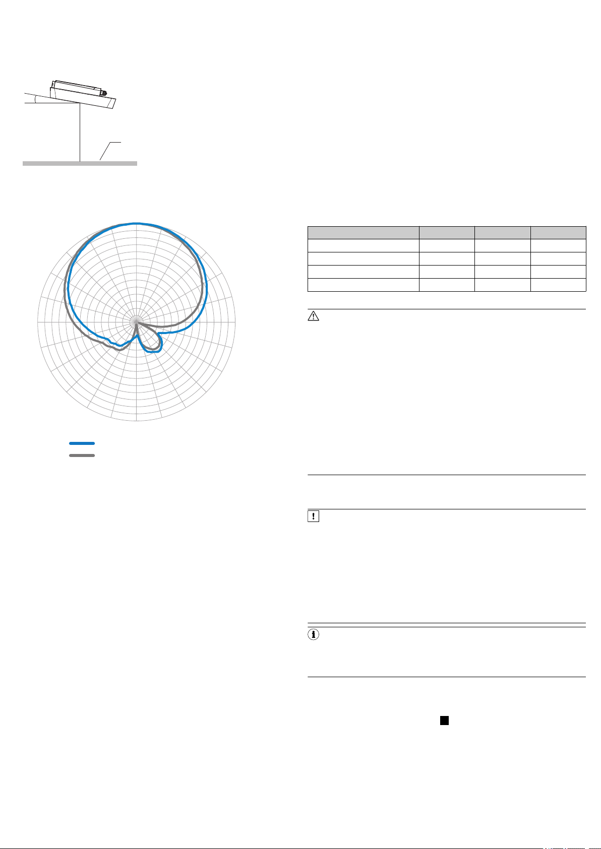
3. Align the surface of the integrated antenna of the RFU630 (front face) and,
where applicable, the additional external antennas, to the data card on the
object. While doing so, take into account the shape, alignment, and dimen‐
sions of the antenna fields. Avoid as far as possible any large metal surfaces
positioned to the front. If this is not possible, do not mount the antenna(s)
plane parallel with the surface.
4. Ensure that there are none of the following possible interference factors
10°
1
0°
15°
30°
45°
60°
75°
90°
105°
120°
135°
150°
165°
180°
–165°
–150°
–135°
–120°
–105°
–90°
–75°
–60°
–45°
–30°
–15°
–33
–30
–27
–24
–21
–18
–15
–12
–9
–6
–3
0
3
6
9
2
1
between the RFU630 and the transponder during the write or read process:
°
Electrically conductive material (e.g. liquids)
°
persons
This also applies for any external antennas used.
The interference factors will absorb or reflect the generated UHF field and
thereby reduce the sensing range.
Supply voltage
•
Supply voltage DC 18 V to 30 V:
°
When the device is connected to the optional SICK CDB650-204 or
CDM420-0006 connection module using a SICK cable.
°
When the device is operated without a connection module using a SICK
cable. 2 A fuse protection at the start of the feeding supply circuit.
•
Optional 12 V to 30 V DC supply voltage when the device is operated without
a connection module using SICK supply cable part no. 6048319
(2 x 0.25 mm2, 10 m). 2.5 A fuse protection.
•
The voltage supply via a power supply unit must be capable of buffering a
brief power failure of 20 ms.
•
The voltage supply or power supply unit must satisfy SELV requirements in
accordance with the currently applicable EN 60950-1. (SELV = Safety Extra
Low Voltage).
Required input voltage on connection module
Voltage drops in the supply circuit affect the connection cable from the connec‐
Figure 1: Selection of the approach angle with a large metal surface on the front.
e.g. 10°
1
Metal surface
Sensing range of the reading and writing field
tion module (CDB650-204 or CDM420-0006) to the device (decrease dependent
on the length) as well as – to a certain extent – the connection module itself. In
order to compensate for this loss when operating the device at the lower end of
the supply range (18 V DC), the following, higher input voltage must be applied to
the connection module:
Cable-dependent input voltages
Cable part no. 6052286 6051194 6051195
Length of cable 2 m 3 m 5 m
CDB650-204 input voltage 19.0 V 19.5 V 20.3 V
Device input voltage 18.0 V 18.0 V 18.0 V
Cable voltage drop 1.0 V 1.5 V 2.3 V
1)
Wire cross-section for supply voltage: 0.14 mm2, AWG 25/26
WARNING
Risk of injury and damage caused by electrical current!
As a result of equipotential bonding currents between the device and other
grounded devices in the system, faulty grounding of the device can give rise
to the following dangers and faults:
•
Dangerous voltages are applied to the metal housings.
•
Devices will behave incorrectly or be destroyed.
•
Cable shielding will be damaged by overheating and cause cable fires.
Remedial measures
•
Only skilled electricians should be permitted to carry out work on the
electrical system.
•
If the cable insulation is damaged, disconnect the voltage supply imme‐
diately and have the damage repaired.
•
Ensure that the ground potential is the same at all grounding points.
•
Where local conditions do not meet the requirements for a safe earthing
Figure 2: Radiation pattern of the internal antenna of the RFU630-131xx (typical):
Measured antenna gain in dBic at 866.5 MHz, RHCP (right-hand circularly polar‐
ized)
1
2
Horizontal plane (azimuth)
Vertical plane (elevation)
For measures for eliminating hazards, see the “Electrical installation” chapter in
the RFU63x/65x RFID read/write device (UHF) operating instructions in the Inter‐
net at: www.sick.com/RFU63x.
The UHF field of the antenna(s) is influenced by its environment, making it impos‐
sible to provide a “clear” demarcation of the sensing range. Application-specific
reflections can result in both overreaches and “holes”. In addition to the read
results, the RFU630 can also output diagnostic data that provide an indication of
the write and read quality. This data can be used to achieve optimum read results
when setting up the system.
The quality of the transponder and the material of the object (plastic, wood,
metal, etc.) also determine the sensing range. The quality of the transponder is
determined by the antenna gain, the integrated transponder chip and the related
sensitivity, and the reflected energy.
The radiation pattern shown here for the internal antenna of the RFU630 was
obtained in a reproducible environment (absorber chamber) for illustrative pur‐
poses. The diagram may therefore only have limited applicability to your specific
application.
3.5 Mounting the CDB650-204 connection module
Mount the CDB650-204 connection module in the vicinity of the device.
b
When using the serial data interfaces (RS-232), the recommended length of
cable between the devices is max. 5 m.
Mount the CDB650-204 in such a way that the device can be accessed at all
times, see the CDB650-204 connection module operating instructions.
4 Electrical installation
•
The electrical installation must only be performed by electrically qualified persons.
•
Standard safety requirements must be met when working on electrical systems.
•
Electrical connections between the RFU630 and other devices may only be
made or separated when there is no power to the system. Otherwise, there is
Connecting the device
1. Connect the communication interface (e.g., Ethernet) of the device directly to
2. If external antennas (max. 3, e.g. RFA630-000 for Europe, India, Russia,
a risk of damaging the devices.
3. Connect the male connector of the “Power/Serial Data/CAN/I/0” connection
4. If necessary, connect a read cycle trigger sensor, such as a photoelectric
•
In the case of open end connecting or extension cables, make sure that bare
wire ends do not touch. This creates a risk of short-circuits if the supply volt‐
age is switched on. Wires must be appropriately insulated from each other.
•
The wire cross-sections in the supply cable from the user’s power system
must be selected in accordance with the applicable national standards.
•
8016526/12XH/2019-03-12/en RFU630-131xx | SICK 2
All circuits connected to the device must be designed as SELV circuits.
method, take appropriate measures (e.g., ensuring low-impedance and
current-carrying equipotential bonding).
NOTICE
Risk of damage to the device due to possible short-circuit!
The supply voltage input for the device is designed with internal circuit protec‐
tion to provide reverse polarity protection. The internal functional earth, which
also corresponds to the negative pole of the supply voltage for the device, is
connected directly to the metal housing of the device due to reasons relating
to high frequency.
If the supply voltage is polarity-reversed, this will not cause any damage pro‐
vided that the following conditions are met for the device:
The device is not connected in an electrically conductive manner, either via
other cables or via its housing, to other peripheral devices which use the
same reference potential.
NOTE
The USB interface of the device is used in industrial environments only as a
service interface for temporary use (e.g. for configuration, troubleshooting).
Permanent use in real operation of the system as a host interface is not
intended.
the PC.
Commissioning: Electrical connection block diagram of the RFU630-131 xx
with optional connection module: A
South Africa, Saudi Arabia, part no. 1058383) are used, connect them to
the antenna connections of the device using appropriate connecting cables
(e.g. part no. 6049780, 2 m).
via a suitable cable (e.g. part no. 6052286, 2 m) to the female connector of
the CDB650-204.
retro-reflective sensor, to the “Sens/IN 1” switching input of the
CDB650-204.
5. Depending on the length of the connecting cable, supply the device with
3
1
7
2
6
5
4
8
13
14
17
15
9
10
12
16
11
6 1 105
11 15
1
43
2
DC voltage between 18 V and 30 V.
✓ After successful initialization, the “Device Ready” LED lights up green.
6. Turn on the PC and start Windows.
Block diagram of all interfaces of the RFU63x-131xx together with the optional
connection module: B
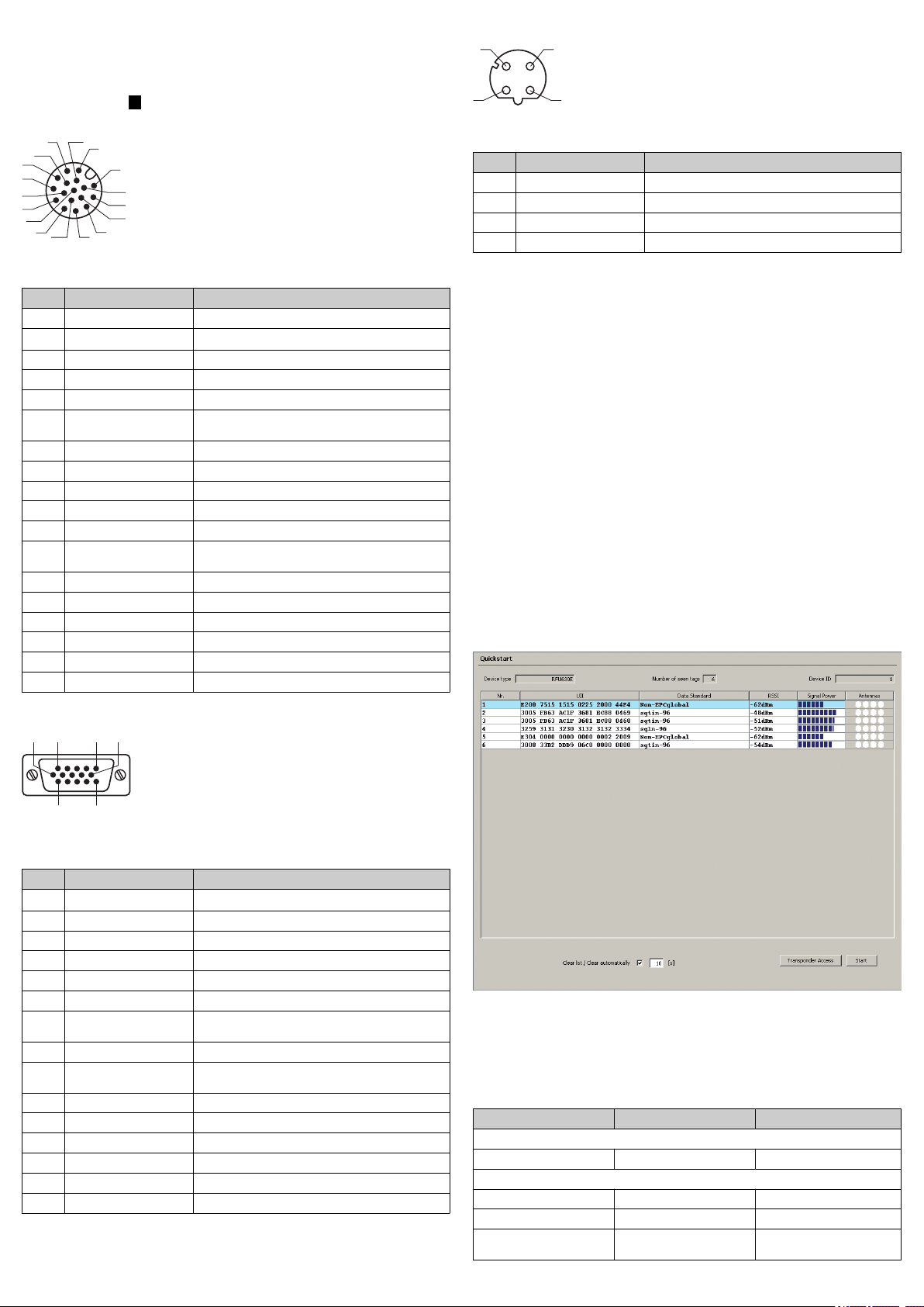
Power/Serial data/CAN/I/O connection
Figure 3: Male connector, M12, 17-pin, A-coding
Pin assignment of the “Power/Serial data/CAN/I/O” connection (M12)
Pin Signal Function
1 GND Ground
2 V
S
Supply voltage
3 CAN L CAN bus (IN/OUT)
4 CAN H CAN bus (IN/OUT)
5 TD+ (RS-422/485), Host Host interface (sender+)
6 TD– (RS-422/485), Host
TxD (RS-232), Host
Host interface (sender-)
7 TxD (RS-232), Aux Aux interface (sender)
8 RxD (RS-232), Aux Aux interface (receiver)
9 SensGND Digital input ground
10 Sensor 1 Digital input 1
11 RD+ (RS-422/485), Host Host interface (receiver+)
12 RD– (RS-422/485), Host
RxD (RS-232), Host
Host interface (receiver–)
13 Result 1 Digital output 1
14 Result 2 Digital output 2
15 Sensor 2 Digital input 2
16 N.c. –
17 N.c. –
– – Screen
M12 adapter cable on D-Sub, e.g. part no. 2055419 (2 m)
Adapter cable (female connector, M12, 17-pin, A-coded/male connector, D-Sub-HD, 15-pin)
Ethernet connection
Figure 5: M12 female connector, 4-pin, D-coded
Pin assignment of the “Ethernet” connection
Pin Signal Function
1 TD+ Sender+
2 RD+ Receiver+
3 TD– Sender–
4 RD– Receiver–
5 Commissioning and configuration with PC (Windows)
Adjustment of the device parameters to the application as well as diagnostics in
the event of malfunctions is undertaken by default with the SOPAS ET configura‐
tion software.
5.1 Installing and starting the configuration software
1. Download and install the latest version of the SOPAS ET configuration soft‐
ware as well as the current device description files (*.sdd): www.sick.com/
SOPAS_ET. In this case, select the “Complete” option as suggested by the
installation wizard. Administrator rights may be required on the PC to install
the software.
2. Start the “SOPAS ET” program option after completing the installation. Path:
Start > Programs > SICK > SOPAS ET Engineering Tool > SOPAS.
3. Establish communication between SOPAS ET and device with the automati‐
cally launching wizard. To do so, select the RFU630 under the devices avail‐
able depending on the connected communication interface, e.g. in the Ether‐
net (default Ethernet address: IP address: 192.168.0.1, subnet mask:
255.255.255.0). SOPAS ET establishes communication with the device and
loads the associated device description file. The Quickstart tab opens.
5.2 Detecting a transponder in Quickstart mode
1. Bring one or more standards-compliant UHF transponders into the working
range of the internal antenna of the device and/or into the working area of
the external antenna(s). The UII/EPC of the individual transponders must be
differentiated so that several transponders can be detected.
2. Click the Start button on the Quickstart tab of SOPAS ET. SOPAS ET generates
an automated read cycle and lists the detected transponders one after
another in the Quickstart window.
Figure 4: Male connector, D-Sub-HD, 15-pin
Pin assignment of the “Power/Serial data/CAN/I/O” connection (D-Sub-HD)
Pin Signal Function
1 V
S
Supply voltage
2 RxD (RS-232), Aux Aux interface (receiver)
3 TxD (RS-232), Aux Aux interface (sender)
4 Sensor 2 Digital input 2
5 GND Ground
6 RD+ (RS-422/485), Host Host interface (receiver+)
7 RD– (RS-422/485), Host
RxD (RS-232), Host
Host interface (receiver–)
8 TD+ (RS-422/485), Host Host interface (sender+)
9 TD– (RS-422/485), Host
TxD (RS-232), Host
Host interface (sender-)
10 CAN H CAN bus (IN/OUT)
11 CAN L CAN bus (IN/OUT)
12 Result 1 Digital output 1
13 Result 2 Digital output 2
14 Sensor 1 Digital input 1
15 SensGND Digital input ground
8016526/12XH/2019-03-12/en RFU630-131xx | SICK 3
Figure 6: SOPAS ET display of the detected transponders in the Quickstart window
Feedback about transponder detection in the UHF field
In Quickstart mode, the default signal of the process feedback LED indicates
whether a UHF field is present and transponders have been detected. The
process feedback LED 8 is in the center of the device front plate, and in this
case, lights up blue.
Process feedback LED
PF LED Status Status
At half brightness
Lights up ON UHF field present
At full brightness
Flashing Flashing slowly (f = 1.25 Hz) 1 transponder in field
Flashing Flashing quickly (f = 2.5 Hz) 2 transponders in field
Flashing Flashing faster (f = 5 Hz) More than 2 transponders in
field
 Loading...