

Page 1
8015215/10QY/2019-09-02
SICK AG
E
rwin-Sick
-Straße 1
D-79183 Waldkirch
www.sick.com
RFU630-041xx
Q U I C K S T A R T e n
1 About this document
The purpose of this Quickstart is to allow you to commission the RFU630-041xx
RFID read/write device (UHF) quickly and easily and to achieve initial read results
with transponders.
The Quickstart is valid for the regional radio variants listed in the “Device
overview” section: see Device overview, page 7.
In the following, the Quickstart refers to the RFU630-041xx (UHF) RFID read/write
device simply as “device”. If variants are to be differentiated in the regional
assignment, the respective device name RFU630-041xx is specified (xx = regional
assignment).
The Quickstart describes the commissioning process for an application with one
device in an ambient temperature range 0 °C to +60 °C.
Commissioning is carried out as an example for the RFU630-04100 device vari‐
ant (Europe region and other countries if necessary, see Device overview,
page 7. The basis is the basic parameter setting of the device. The optional
CDB650-204 connection module handles the industrial-standard signal distribu‐
tion for the device. Other connection modules are available.
All rights reserved. Subject to change without notice.
Supplementary documents
Information, such as application examples and downloads of associated docu‐
ments (e.g. operating instructions) and software, can be found on the SICK prod‐
uct page on the Internet at: www.sick.com/RFU63x. For an overview see Sources
for obtaining more information, page 8 in this Quickstart.
More detailed information on mounting and electrically installing the device as a
stand-alone unit than provided in this Quickstart is available in the RFU630-041xx
RFID read/write device (UHF) operating instructions. The operating instructions
add the following information to the Quickstart:
•
Requirements and notes for mounting and electrical installation at operating
ambient temperatures below 0 °C
•
For applications in widely distributed systems: Notes on the suppression of
ground potential equalizing currents
2 Safety information
•
This chapter is dedicated to the safety of commissioning personnel and the
operator of the system in which the device is integrated.
•
Read this Quickstart carefully to familiarize yourself with the device and its
functions before commissioning the device. The Quickstart is considered a
part of the device and must be kept in an accessible location in the immedi‐
ate vicinity of the device at all times!
•
The radiated power of the external antenna(s) used must not exceed the
maximum value permitted for each specific country, see Technical data,
page 5 and see Device overview, page 7.
Electromagnetic radiation
WARNING
Health hazard as a result of high-frequency electromagnetic radiation!
The RFU630-04100 (Europa/South Africa region and possibly other countries)
is designed for operation in accordance with ETSI EN 302208. During opera‐
tion with the external RFA630-x00 antenna(s), the human exposure regulations
covered by EN 50364 must be observed.
Limit human exposure to electromagnetic fields. Suitable safety dis‐
b
tances must be maintained during both short-term and long-term work
in the radiation range of the external antenna(s).
Minimum distances to be maintained between the antenna and the
human body during long-term transmission according to ETSI:
°
30 cm at maximum antenna radiation power of 2 W ERP
°
15 cm at reduced radiation power of 1 W ERP
°
The RFU630-04101 (USA/Canada region and possibly other countries) satis‐
fies the limit values of the FCC for exposure to radiation in an uncontrolled
environment.
b
Complete region assignment of the RFU630-041xx see Device overview,
page 7.
Prerequisites for enclosure rating IP
8015215/10QY/2019-09-02/en RFU630-041xx | SICK 1
10 cm at radiation power of 0.5 W ERP
During operation with external RFA630-x01 antenna(s), a safety distance
of at least 30 cm must be maintained between the antenna and the
human body.
•
To comply with the IP67 enclosure rating in operation, the following require‐
ments must be met. If this is not done, the device does not fulfill any speci‐
fied IP enclosure rating.
°
The side cover for both the USB female connector and the microSD
card slot must be screwed tight to the device. Recommended tightening
torque for the cover screws: 40 Ncm ± 5 Ncm.
°
The SICK cables plugged into the M12 and TNC connections must be
screwed tight.
°
Any electrical connections that are not being used must be fitted with
protective caps or plugs that are screwed tight (as in the delivery condi‐
tion).
°
Any electrical connections for external antennas (TNC reverse) that are
not being used must be fitted with screw-on protective caps (as in the
delivery condition).
°
Only operate the device without a cover for a short period while insert‐
ing or removing the memory card or temporarily using the USB inter‐
•
Standard IP technology
2.1 Intended use
The RFU630-041xx is an intelligent RFID read/write device (UHF) from the
RFU63x product family. The stationary device automatically identifies wirelessbased data cards (transponders) on stationary and moving objects. The device
also supports data card management.
The device is a compact read and write unit that uses a maximum of 4 external
antennas to process all current, passive transponders in accordance with
ISO/IEC 18000-6C and EPCglobal UHFC1G2 in the regionally-dependent UHF car‐
rier frequency range. The device does not contain any integrated antennas.
Intelligent process logic enables processing either as a stand-alone solution or as
part of a group in a network. The device sends the read results to a higher-level
computer via its host interface. The computer coordinates further processing.
The device receives corresponding commands for data card management (write,
read, etc.) via its host interface.
Device variants refer to the region assignment (operating permit and carrier fre‐
quency range), see Device overview, page 7.
Intended use of the device also includes compliance with all information in this
Quickstart.
face. During this time, protect the device against moisture and dust.
Opening the screws of the device housing will invalidate any warranty claims
against SICK AG. For further warranty provisions, see the General Terms and
Conditions of SICK AG, e.g. on the delivery note of the device.
NOTE
SICK uses standard IP technology in its products. The emphasis is
placed on availability of products and services.
SICK always assumes the following prerequisites:
•
The customer ensures the integrity and confidentiality of the data
and rights affected by its own use of the aforementioned products.
•
In all cases, the customer implements the appropriate security
measures, such as network separation, firewalls, virus protection,
and patch management.
NOTE
The device approval was granted for a specific region. The region assignment
cannot be changed.
•
Only use the device in the region and the country for which it has been
approved.
•
When reselling the device, inform the buyer of the fixed region assign‐
ment.
•
Should the device be passed on to a third party, these operating instruc‐
tions and the Quickstart should be handed over with it.
•
For country-specific particulars to consider when operating the device,
see Operational restrictions, page 7.
3 Device description
3.1 Device view
Dimensional drawing of the RFU63x-041xx, unit: mm (inch), decimal separator:
period: A
Dimensions of the threaded mounting holes of the RFU630-041xx, unit: mm
(inch), decimal separator: period: B
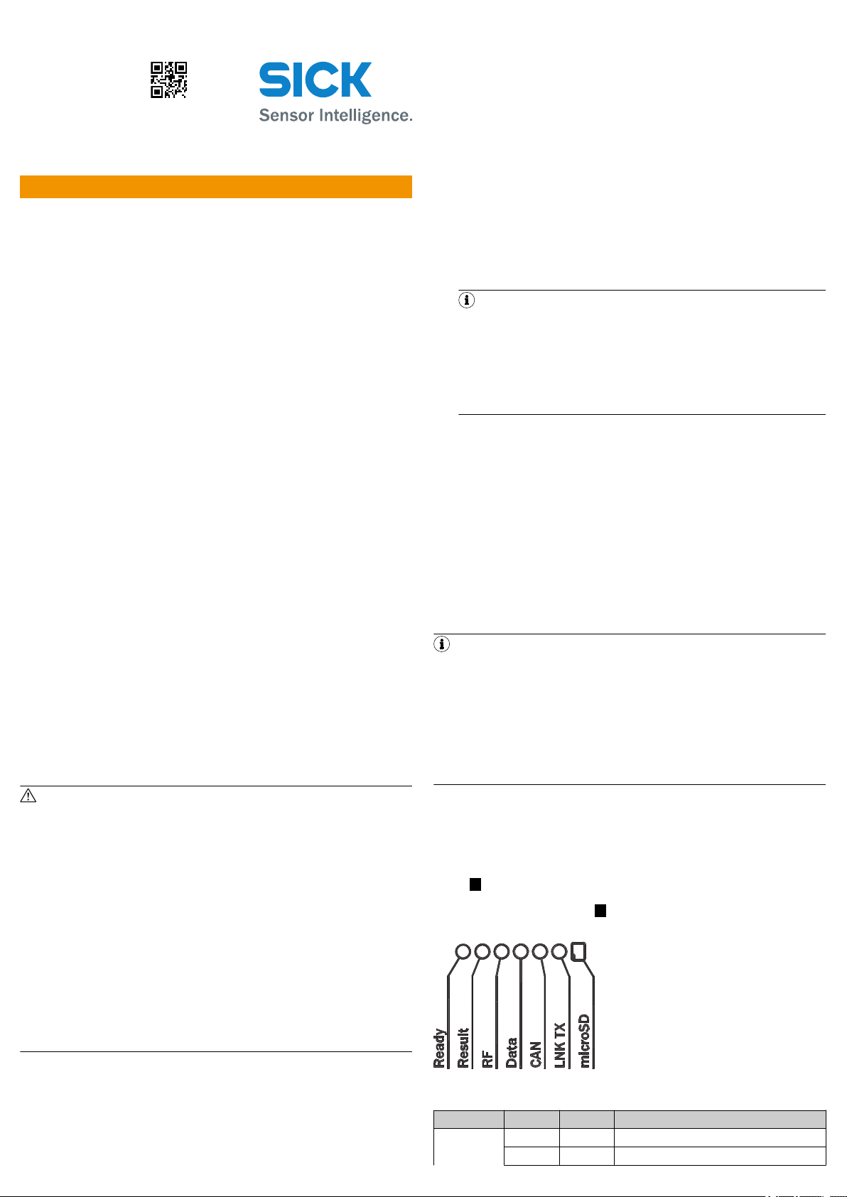
3.2 Status displays
Figure 1: Status indicators on the first display level
Status displays
Advertisement LED Color Status
Ready Lights up Green The device is ready for use.
Lights up Red The device is not ready for use: hardware fault
Page 2
Advertisement LED Color Status
3 2
1
Flashing Green PROFINET operation (single por t):
Flashing Red
The LEDs flash cyclically and alternating 4 x red, 1
x green.
•
The device attempts to establish a connec‐
tion to a PLC (IO controller)
– or –
•
During operation: the connection between
the device and the PLC (IO controller) is
interrupted
Result Lights up Green Read or write was successful
RF Lights up Green The UHF field is switched on.
Lights up Red External antenna(s) fault:
•
All antennas are deactivated.
•
Antenna(s) in the device is/are activated
but not connected, or cable defective.
Data Lights up Green Data output via the host interface
CAN Lights up Orange Data traffic via CAN bus (CAN Rx)
Link/ActLNKTXLights up Green Data traffic on the Ethernet interface
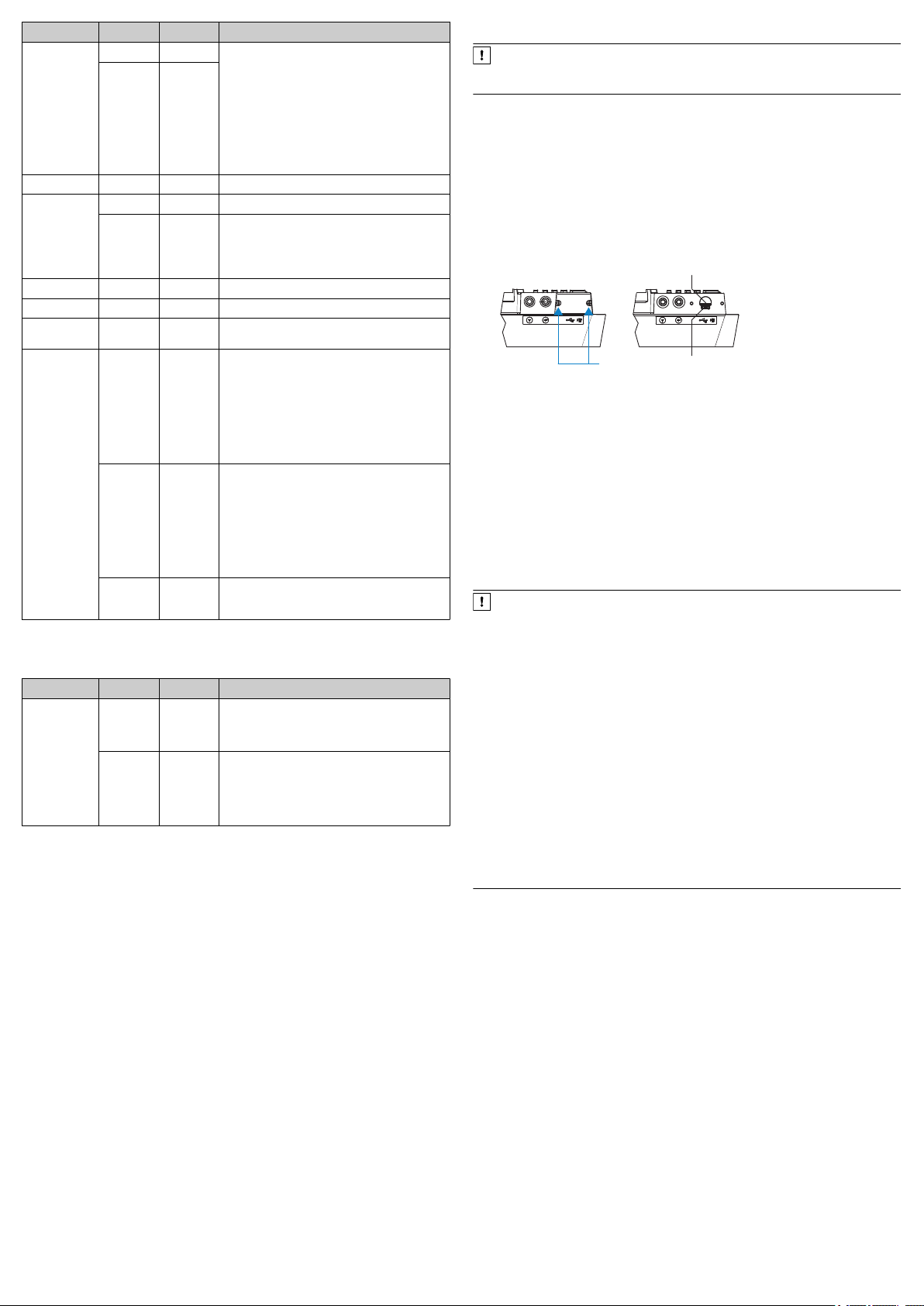
Inserting the memory card
NOTICE
To avoid damaging the memory card, make sure there is no power to the
device when you insert or remove it.
The card slot can be accessed on the device behind the aluminum cover, see
Device description, page 1.
Maintaining enclosure rating IP67: see Safety information, page 1.
1. Switch off the supply voltage to the device.
2. To remove the cover, unscrew both Allen screws (A/F 2).
3. Making sure it is in the correct position (with the contacts pointing to the
front and down – see the symbol on the device), insert the memory card into
the card slot until it locks into place.
4. Screw the aluminum cover back on. Recommended tightening torque for the
cover screws: 40 Ncm ± 5 Ncm.
5. Switch the supply voltage for the device back on.
microSD Lights up Green The memory card is inser ted and ready for opera‐
tion.
•
In this state, the device can either write
data to the memory card or read data on
the card.
•
If the LED lights up, however, this does not
indicate that the device is accessing the
card!
Lights up Red The memory card is inser ted.
However, the device cannot read data on the
memory card.
Possible causes:
•
The memory card does not contain any
data
•
The content is not readable
•
The memory card is defective
Lights up Orange 1)A function is star ted with SOPAS ET which
1)
Prerequisite: In SOPAS ET, the “SD card required” function has been activated under the
“Service” user level.
requires a memory card for writing. However, the
memory card is not connected.
Additional indicators for ambient temperatures below –20 °C
Display LED Color Status
Ready Flashing Orange Flashing, frequency 1 Hz.
Flashing Green Flashing, frequency 1 Hz.
1)
For firmware version V2.02 or higher.
The device is not ready for use.
The internal temperature of the device is below
-25 °C (-30 °C)
The device is not ready for use.
The internal temperature of the device is between
-25 °C (-30 °C) 1) and -20 °C. After an approx.
2 min warm-up phase, the device starts regular
operation.
1)
Audible status indicator (beeper)
Default: 1 sound when at least one transponder is in the UHF field
3.3 microSD memory card (optional accessory)
Function
The device can execute the following functions on the plug-in memory card:
•
Automated, additional storage of the internal parameter set to an external
storage medium (cloning function), if available. This is done in the framework
of the recommended safety concept for the 4Dpro device parameter sets.
The function is triggered by saving the internal parameter set with the “per‐
manent” option. The function is used, among other things, to conveniently
transmit the parameter set to an exchange unit of the same type in the event
of an error. Optional external media include a memory card which can be
plugged into the device or the CMC600 parameter storage module, which
can be used in the optional connection module, e.g., CDB650-204 or
CDM420-0006.
•
Continuous recording of diagnostic read data after the first manual start,
e.g., via SOPAS ET. Recording is resumed after a device restart when the
function is set permanently.
The first time a parameter set is stored, we recommend that an empty memory
card is used (if necessary, check and delete the contents of the card on the PC
using a card reader).
The memory card is not included with delivery.
Only use types approved by SICK to ensure reliable function of the memory card,
see www.sick.com/RFU63x. The memory card has no write protection that can be
activated.
Figure 2: USB connection and slot for microSD memory card
1
2
3
Slot for microSD memory card
USB port (female connector, Micro-B, 5-pin)
2 x screw, (Allen screw, A/F 2 mm)
6. Once it is switched on, the device automatically detects the presence of a
memory card and, depending on the card’s content, behaves as follows:
°
If the card is empty or if it contains a parameter set that cannot be
interpreted by the device, the device saves its currently valid internal
parameter set to the card (provided there is sufficient storage space)
and starts with the internal parameter set.
°
If the card contains a parameter set that can be interpreted by the
device, the device overwrites the currently valid internal parameter set
with this external parameter set.
The goal is for the internal parameter set and the parameter set saved
externally to always be identical.
NOTICE
Possible data loss or irreparable damage to the memory card!
The “microSD” LED lights up green when a memory card which is ready for
operation is inserted into the device. In this state, the device can either read
data from the card or write data to the card. Access to the card itself is not
signaled by the device (compare electronic camera with memory card).
The “microSD” LED lights up yellow when, for example, a function which
requires a memory card has been started manually with SOPAS ET and the
card is not ready for operation (e.g., not inserted, contacts are contaminated,
or no free storage space).
To avoid damaging the memory card, make sure there is no power to the
b
device when you insert or remove it.
If parameter values are changed with the “permanent” option in the
b
device using the SOPAS ET configuration software while the memory
card is inserted or if functions are started which access the memory
card (e.g., logging of data), do not remove the memory card and do not
switch off the supply voltage.
In order to remove the memory card in a controlled manner while work‐
b
ing with SOPAS ET when the device is switched on, select the Remove SD
card function under Analysis/SD card and wait for confirmation from
SOPAS ET.
4 Mounting
4.1 Scope of delivery
•
Device in the version ordered (region assignment). Electrical connections fit‐
ted with protective caps or plugs. Without connecting cables and brackets.
Required external antennas, only if ordered as optional extra.
•
Printed Quickstart, language versions dependent on region: see Device
overview, page 7. Copies in other languages may be available in PDF for‐
mat on the device product page on the Internet at: www.sick.com/RFU63x.
4.2 Equipment required
•
4 x M6 screws or 3 x M5 screws for mounting the device on a mounting
device (bracket) provided by the user. The screw length depends on the
mounting base (wall thickness of the bracket).
•
When using an optional SICK bracket, the screws for mounting the device on
the bracket are included in the scope of delivery of the bracket.
4.3 Mounting requirements
•
The permissible ambient conditions for operating the device must be
observed, e.g. assigned radio region, ambient temperature, see Technical
data, page 5 and ground potential see Electrical installation, page 3.
•
The device must be mounted using all 4 M6 or 3 M5 blind tapped holes pro‐
vided, see Device view, page 1.
8015215/10QY/2019-09-02/en RFU630-041xx | SICK 2
Page 3
•
10°
1
0°
15°
30°
45°
60°
75°
90°
105°
120°
135°
150°
165°
180°
–165°
–150°
–135°
–120°
–105°
–90°
–75°
–60°
–45°
–30°
–15°
–33
–30
–27
–24
–21
–18
–15
–12
–9
–6
–3
0
3
6
9
2
1
If necessary, stable mounting equipment with sufficient load-bearing capac‐
ity and appropriate dimensions for the device. Weight of the device (without
cables): see Technical data, page 5, device dimensions: see Device view,
page 1.
•
Make sure there is no electrically conductive material between transponder
and device.
4.4 Mounting the device
1. Select a suitable mounting location for the device. This depends on the
lengths of cable chosen for the external antennas.
2. Optional: Attach the separately ordered SICK mounting accessories to the
device. Otherwise, use suitable screws to mount the device on the bracket
provided by the user. Observe the maximum screw-in depth of the blind hole
thread here, see Device view, page 1.
3. The mounting location and position of the external antenna(s) depend on
their antenna fields and the transponders used.
4. Align the surface of the external antenna(s) to the data card on the object.
While doing so, take into account the shape, alignment, and dimensions of
the antenna fields. Avoid as far as possible any large metal surfaces posi‐
tioned to the front. If this is not possible, do not mount the antenna(s) plane
parallel with the surface.
4.5 Mounting the CDB650-204 connection module
Mount the CDB650-204 connection module in the vicinity of the device.
b
When using the serial data interfaces (RS-232), the recommended length of
cable between the devices is max. 5 m.
Mount the CDB650-204 in such a way that the device can be accessed at all
times, see the CDB650-204 connection module operating instructions.
5 Electrical installation
•
The electrical installation must only be performed by electrically qualified persons.
•
Standard safety requirements must be met when working on electrical systems.
•
Electrical connections between the RFU630 and other devices may only be
made or separated when there is no power to the system. Otherwise, there is
a risk of damaging the devices.
•
In the case of open end connecting or extension cables, make sure that bare
wire ends do not touch. This creates a risk of short-circuits if the supply volt‐
age is switched on. Wires must be appropriately insulated from each other.
•
The wire cross-sections in the supply cable from the user’s power system
must be selected in accordance with the applicable national standards.
•
All circuits connected to the device must be designed as SELV circuits.
Supply voltage
•
Supply voltage DC 18 V to 30 V:
°
When the device is connected to the optional SICK CDB650-204 or
CDM420-0006 connection module using a SICK cable.
°
When the device is operated without a connection module using a SICK
cable. 2 A fuse protection at the start of the feeding supply circuit.
•
Optional 12 V to 30 V DC supply voltage when the device is operated without
a connection module using SICK supply cable part no. 6048319
(2 x 0.25 mm2, 10 m). 2.5 A fuse protection.
•
The voltage supply via a power supply unit must be capable of buffering a
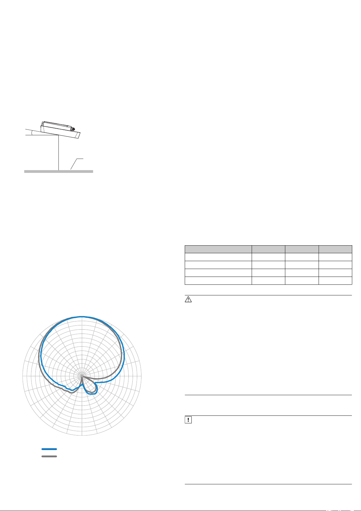
Figure 3: Select the approach angle of the antenna with large frontal metal
surface, e. g. 10°
1
Metal surface
5. Ensure there is no electrically conductive material (e.g., metal, liquids) or
persons between the device and the transponder during the write or read
process. This will absorb or reflect the generated UHF field and thereby
reduce the sensing range.
Sensing range of the read and write field of the RFA630-x00 antenna
The environment can influence the UHF field or antenna(s), making it impossible
to provide a “clear” demarcation of the sensing range. Application-specific reflec‐
tions can result in both overreaches and “holes”. For estimation purposes, the
device can also output diagnostic data that provides an indication of the read and
write quality in addition to the read results. This data can be used to achieve opti‐
mum read results when setting up the system.
The quality of the transponder and the material of the object (plastic, wood,
metal) also determine the sensing range.
The quality of the transponder is determined by:
•
the antenna gain
•
the integrated transponder chip and the related sensitivity, and the reflected
energy
The radiation pattern shown here for the external UHF antenna of the RFA630-x00
was obtained in a reproducible environment (absorber chamber) for illustrative
purposes. The diagram may therefore only have limited applicability to your spe‐
cific application.
brief power failure of 20 ms.
•
The voltage supply or power supply unit must satisfy SELV requirements in
accordance with the currently applicable EN 60950-1. (SELV = Safety Extra
Low Voltage).
Required input voltage on connection module
Voltage drops in the supply circuit affect the connection cable from the connec‐
tion module (CDB650-204 or CDM420-0006) to the device (decrease dependent
on the length) as well as – to a certain extent – the connection module itself. In
order to compensate for this loss when operating the device at the lower end of
the supply range (18 V DC), the following, higher input voltage must be applied to
the connection module:
Cable-dependent input voltages
Cable part no. 6052286 6051194 6051195
Length of cable 2 m 3 m 5 m
CDB650-204 input voltage 19.0 V 19.5 V 20.3 V
Device input voltage 18.0 V 18.0 V 18.0 V
Cable voltage drop 1.0 V 1.5 V 2.3 V
1)
Wire cross-section for supply voltage: 0.14 mm2, AWG 25/26
WARNING
Risk of injury and damage caused by electrical current!
As a result of equipotential bonding currents between the device and other
grounded devices in the system, faulty grounding of the device can give rise
to the following dangers and faults:
•
Dangerous voltages are applied to the metal housings.
•
Devices will behave incorrectly or be destroyed.
•
Cable shielding will be damaged by overheating and cause cable fires.
Remedial measures
•
Only skilled electricians should be permitted to carry out work on the
electrical system.
•
If the cable insulation is damaged, disconnect the voltage supply imme‐
diately and have the damage repaired.
•
Ensure that the ground potential is the same at all grounding points.
•
Where local conditions do not meet the requirements for a safe earthing
method, take appropriate measures (e.g., ensuring low-impedance and
current-carrying equipotential bonding).
NOTICE
Risk of damage to the device due to possible short-circuit!
The supply voltage input for the device is designed with internal circuit protec‐
For measures for eliminating hazards, see the “Electrical installation” chapter in
the RFU63x/65x RFID read/write device (UHF) operating instructions in the Inter‐
net at: www.sick.com/RFU63x.
tion to provide reverse polarity protection. The internal functional earth, which
also corresponds to the negative pole of the supply voltage for the device, is
connected directly to the metal housing of the device due to reasons relating
to high frequency.
Figure 4: Radiation pattern of the RFA630-x00 external UHF antenna (typical):
Measured antenna gain in dBic at 866.5 MHz, RHCP (right-hand circularly polar‐
ized)
1
2
8015215/10QY/2019-09-02/en RFU630-041xx | SICK 3
Horizontal plane (azimuth)
Evaluation level (vertical)
If the supply voltage is polarity-reversed, this will not cause any damage pro‐
vided that the following conditions are met for the device:
The device is not connected in an electrically conductive manner, either via
other cables or via its housing, to other peripheral devices which use the
same reference potential.
Page 4

NOTE
3
1
7
2
6
5
4
8
13
14
17
15
9
10
12
16
11
6 1 105
11 15
1
43
2
The USB interface of the device is used in industrial environments only as a
service interface for temporary use (e.g. for configuration, troubleshooting).
Permanent use in real operation of the system as a host interface is not
intended.
Connecting the device
1. Connect the communication interface (e.g., Ethernet) of the device directly to
the PC.
Commissioning: Electrical connection block diagram of the RFU630-041 xx
with optional connection module: C
2. Connect external antennas (max. 4, e.g. RFA630-000 for Europe, India, Rus‐
sia, South Africa, Saudi Arabia part no. 1058383) to the antenna connec‐
tions of the device using appropriate connecting cables (e.g.
part no. 6049780, 2 m). At least one antenna is required! The
RFU630-041xx does not have its own antenna.
3. Connect the male connector of the “Power/Serial Data/CAN/I/0” connection
via a suitable cable (e.g. part no. 6052286, 2 m) to the female connector of
the CDB650-204.
4. If necessary, connect a read cycle trigger sensor, such as a photoelectric
retro-reflective sensor, to the “Sens/IN 1” switching input of the
CDB650-204.
5. Depending on the length of the connecting cable, supply the device with
DC voltage between 18 V and 30 V.
✓ After successful initialization, the “Device Ready” LED lights up green.
6. Turn on the PC and start Windows.
Block diagram of all interfaces of the RFU63 x-041 xx together with the optional
connection module: D
Power/Serial data/CAN/I/O connection
Pin Signal Function
5 GND Ground
6 RD+ (RS-422/485), Host Host interface (receiver+)
7 RD– (RS-422/485), Host
RxD (RS-232), Host
Host interface (receiver–)
8 TD+ (RS-422/485), Host Host interface (sender+)
9 TD– (RS-422/485), Host
TxD (RS-232), Host
Host interface (sender-)
10 CAN H CAN bus (IN/OUT)
11 CAN L CAN bus (IN/OUT)
12 Result 1 Digital output 1
13 Result 2 Digital output 2
14 Sensor 1 Digital input 1
15 SensGND Digital input ground
Ethernet connection
Figure 7: M12 female connector, 4-pin, D-coded
Pin assignment of the “Ethernet” connection
Pin Signal Function
1 TD+ Sender+
2 RD+ Receiver+
3 TD– Sender–
4 RD– Receiver–
Figure 5: Male connector, M12, 17-pin, A-coding
Pin assignment of the “Power/Serial data/CAN/I/O” connection (M12)
Pin Signal Function
1 GND Ground
2 V
S
Supply voltage
3 CAN L CAN bus (IN/OUT)
4 CAN H CAN bus (IN/OUT)
5 TD+ (RS-422/485), Host Host interface (sender+)
6 TD– (RS-422/485), Host
TxD (RS-232), Host
Host interface (sender-)
7 TxD (RS-232), Aux Aux interface (sender)
8 RxD (RS-232), Aux Aux interface (receiver)
9 SensGND Digital input ground
10 Sensor 1 Digital input 1
11 RD+ (RS-422/485), Host Host interface (receiver+)
12 RD– (RS-422/485), Host
RxD (RS-232), Host
Host interface (receiver–)
13 Result 1 Digital output 1
14 Result 2 Digital output 2
15 Sensor 2 Digital input 2
16 N.c. –
17 N.c. –
– – Screen
M12 adapter cable on D-Sub, e.g. part no. 2055419 (2 m)
Adapter cable (female connector, M12, 17-pin, A-coded/male connector, D-Sub-HD, 15-pin)
6 Commissioning and configuration with PC (Windows)
Adjustment of the device parameters to the application as well as diagnostics in
the event of malfunctions is undertaken by default with the SOPAS ET configura‐
tion software.
6.1 Installing and starting the configuration software
1. Download and install the latest version of the SOPAS ET configuration soft‐
ware as well as the current device description files (*.sdd): www.sick.com/
SOPAS_ET. In this case, select the “Complete” option as suggested by the
installation wizard. Administrator rights may be required on the PC to install
the software.
2. Start the “SOPAS ET” program option after completing the installation. Path:
Start > Programs > SICK > SOPAS ET Engineering Tool > SOPAS.
3. Establish communication between SOPAS ET and device with the automati‐
cally launching wizard. To do so, select the RFU630 under the devices avail‐
able depending on the connected communication interface, e.g. in the Ether‐
net (default Ethernet address: IP address: 192.168.0.1, subnet mask:
255.255.255.0). SOPAS ET establishes communication with the device and
loads the associated device description file. The Quickstart tab opens.
6.2 Detecting a transponder in Quickstart mode
1. Bring one or more standards-compliant UHF transponders into the working
range of the external antenna(s). The UII/EPC of the individual transponders
must be differentiated so that several transponders can be detected.
2. Click the Start button on the Quickstart tab of SOPAS ET. SOPAS ET generates
an automated read cycle and lists the detected transponders one after
another in the Quickstart window.
Figure 6: Male connector, D-Sub-HD, 15-pin
Pin assignment of the “Power/Serial data/CAN/I/O” connection (D-Sub-HD)
Pin Signal Function
1 V
2 RxD (RS-232), Aux Aux interface (receiver)
3 TxD (RS-232), Aux Aux interface (sender)
4 Sensor 2 Digital input 2
8015215/10QY/2019-09-02/en RFU630-041xx | SICK 4
S
Supply voltage
Figure 8: SOPAS ET display of the detected transponders in the Quickstart window
Page 5

Feedback about transponder detection in the UHF field
In Quickstart mode, the default signal of the process feedback LED indicates
whether a UHF field is present and whether the device has detected transpon‐
ders. The process feedback LED is in the center of the device front plate, and in
this case, lights up blue.
Process feedback LED
PF LED Status Status
At half brightness
Lights up ON UHF field present
At full brightness
Flashing Flashing slowly (f = 1.25 Hz) 1 transponder in field
Flashing Flashing quickly (f = 2.5 Hz) 2 transponders in field
Flashing Flashing faster (f = 5 Hz) More than 2 transponders in
NOTE
Quickstart mode is not intended to be used during normal operation. For
operational use, set a read cycle using the object trigger control in SOPAS ET.
6.3 Accessing the data on a transponder
1. In order to access the memory area of a transponder, click the Stop button in
Quickstart.
2. Highlight the desired transponder (click it with the mouse).
3. Click the Transponder Access button. The Transponder Management Access tab dis‐
plays the content of the selected transponder.
field
°
Regional permissible values for the antennas, see Device overview,
page 7.
°
RFU630 transmitting power default: 23 dBm (200 mW)
Figure 10: SOPAS ET: Example setting for external antenna 2
3. The line loss of the antenna connecting cable as well as the gain of the
external antenna used must also be entered here.
4. Test and, if necessary, modify the settings made during operational use of
the system.
6.5 Completing the configuration
Permanently save the entire configuration once it has been successfully
b
tested:
°
Parameter set in the device: Click the button
°
Configuration file on the PC: Click buttons Device > Export SDV file.
.
7 Maintenance and care
The device does not contain components that require maintenance.
If they are contaminated (e.g., metal dust), clean the front of the external
antennas carefully using a soft, damp cloth (with a mild cleaning agent) in
order to achieve the full read and write speed. The antenna hoods are made
of plastic.
Figure 9: Transponder Access SOPAS ET display window
NOTE
The TID (tag identifier) of the transponder cannot be changed.
6.4 Continuing the configuration
1. Under SOPAS ET in the left-hand navigation tree, edit the required tabs for
the application using the additional entries under Parameters.
These include amongst others:
°
antenna configuration, performance optimization, data pre-processing,
transponder processing
°
Object trigger control (e.g. via digital input “Sensor 1”), data processing
and output
°
Data output interface(s), function of the digital inputs and outputs and
2. On the Antenna Configuration tab, set the transmitting power for the individual
use of an optional MicroSD memory card if necessary.
external antenna(s) using sliders.
8 Transport and storage
Transport and store the device in the original packaging, with protective plugs and
caps completely screwed-on. Do not store outdoors. To ensure that any residual
moisture present can escape, do not store the device in airtight containers. Do
not expose to any aggressive substances.
Storage conditions: dry, dust-free, no direct or indirect sunlight, as little vibration
as possible, storage temperature and relative humidity see Technical data,
page 5.
9 Repairs
Repair work on the device may only be performed by qualified and authorized ser‐
vice personnel from SICK AG.
10 Disassembly and disposal
Any device which can no longer be used must be disposed of in an environmen‐
tally friendly manner in accordance with the applicable country-specific waste dis‐
posal regulations. As it is categorized as electronic waste, the device must never
be disposed of with household waste!
11 Technical data
11.1 Features
RFU63x-041xx
Version
(Working area)
Product category RFID read/write device (UHF) without integrated antenna
Frequency band UHF (860 MHz ... 960 MHz)
Radio equipment
approval
(Regional assignment)
Carrier frequency
Transmission output
power
RFID standard (air inter‐
face)
Modulation PR-ASK, DSB-ASK
Connection type Ethernet
Scanning range ≤ 10 m
Antenna
Long range
Depending on type: Device overview
EPCglobal UHF Class 1 Generation 2, ISO/IEC 18000-6C
1)
Only external antennas
•
Maximum 4 external antennas, mono-static
•
Transmitting power per antenna: up to +30 dBm,
adjustable
8015215/10QY/2019-09-02/en RFU630-041xx | SICK 5
Page 6

RFU63x-041xx
Service functions Semi-automated saving of parameter data (parameter cloning)
outside the device memory:
•
Using insertable microSD memor y card 2) in the device
•
Externally via the CMC600 2) parameter cloning module in
the CDB 2) or CDM 2) connection module
•
Externally via the CDF 2) fieldbus module
Clock Network time protocol (NTP), no internal clock
Conformities Type-dependent. See type-specific online data sheet at:
Certificates Type-dependent. See “Downloads” section online at:
1)
Depending on the transponders used, the external antenna(s) and the ambient condi‐
tions.
2)
Optional accessories.
www.sick.com/RFU63x
www.sick.com/RFU63x
11.2 Interfaces
RFU63x-041xx
Ethernet
PROFINET
•
Protocol: TCP/IP
•
Function: host (data output of the read result)
•
Function: Aux for service
•
Data transmission rate 10/100 Mbit/s
•
Services: DHCP, NTP, HTTP/HTTPS
•
Protocol: PROFINET
•
Function: host (data output of read result), PROFINET Sin‐
2)
gle Port
•
Data transmission rate 10/100 Mbit/s
•
PROFINET dual port: via an external CDF600-22xx 3) field‐
1)
bus module
EtherNet/IP™
EtherCAT®
PROFIBUS
Serial
•
Protocol: EtherNet/IP™
•
Function: host (data output of the read result)
•
Data transmission rate 10/100 Mbit/s
•
Protocol: EtherCAT®
•
Function: host (data output of the read result)
•
Via external CDF600-0300 3) fieldbus module (gateway
mode) to EtherCAT®
•
Protocol: PROFIBUS
•
Function: host (data output of the read result)
•
Via external CDF600-21xx 3) fieldbus module to PROFIBUS
2)
(RS-485)
2)
Host:
•
Protocol: RS-232, RS-422/485
•
Function: host (data output of the read result)
•
Data transmission rate: 0.3 kBd ... 115.2 kBd
•
Cable: RS-422 (4-wire + ground), RS-485 (4-wire +
ground)
•
Cable: RS-232 (2-wire + ground)
Aux:
•
CAN
4)
USB 2.0
Digital inputs
Protocol: RS-232
•
Function: Aux for service
•
Data transmission rate: 57.6 kBd
•
Cable: RS-232 (2-wire + ground)
•
Protocol:
°
CSN (SICK CAN sensor network)
°
•
•
•
CANopen
Function: host (data output of the read result)
Data transmission rate: 20 kBit/s ... 1 MBit/s
Bus length: depends on data transmission rate and length
of cable. Typical: 250 m at 250 kBit/s and wire cross-sec‐
tion ≥ 0.34 mm
•
Function: Aux (USB 2.0) for service
•
Quantity: 2
•
Version: physical, switching
•
Optional 2 additional external logical inputs (sof tware-
1)
2
1)
controlled) via CMC600 3) module in the CDB 3) or CDM
connection module
5)
•
V
= max. 30 V, Iin 6) = max. 5 mA
in
•
Opto-decoupled, reverse polarity protected, adjustable
debounce time
Digital outputs
•
Quantity: 2
•
Version: physical, switching
•
Optional 2 additional external logical outputs (softwarecontrolled) via CMC600 3) module in the CDB 3) or CDM
connection module
•
•
8)
V
7) = VS
out
– 1.5 V, I
Short-circuit protected, temperature protected, not electri‐
9)
≤ 100 mA (typical)
out
cally isolated from the supply voltage
Optical indicators 7 x RGB LEDs (status indicators) on front top
Acoustic indicator Beeper (buzzer), can be deactivated.
Operating elements 2 x pushbut tons (select and start/stop functions)
Configuration SOPAS ET configuration software, CoLa commands (telegrams),
Programming Application-specific programming with SICK AppStudio
1)
For example: configuration, diagnosis, transponder access or display of the read results.
2)
Function blocks for PLC types from different manufacturers are available online at:
www.sick.com/RFU63x.
3)
Optional accessories.
4)
USB interface only for temporary use (service)
5)
Input voltage.
6)
Input current.
7)
Output voltage.
8)
Supply voltage.
9)
Output current.
10)
e.g. with SOPAS ET configuration software.
11)
Functions can be enabled with the SDK6U SD card. Available at: www.sick.com
11.3 Mechanics/electronics
Electrical connection
Supply voltage V
Power consumption
Housing Aluminum die cast, polycarbonate
Housing color Blue, black, silver
Side cover
MTBF 14 years
Enclosure rating IP67 (EN 60529:1991-10/A2:2000-02)
Protection class III (EN 61140:2006-08)
Safety EN 60950-1:2006-04/A11: 2009-03/A1: 2010-03/A12:
Weight Approx. 2.1 kg
Dimensions (L x W x H) 239 mm x 197 mm x 40 mm
1)
When connected to the optional SICK CDB650-204 or CDM420-0006 connection mod‐
ule using a SICK cable.
2)
When operated without a connection module using a SICK cable. 2 A fuse protection at
the start of the feeding supply circuit.
3)
When operated without a connection module using a SICK supply cable part no.
6048319 (2 x 0.25 mm2, 10 m). 2.5 A fuse protection at the start of the feeding supply
circuit.
4)
3)
At full transmitting power and unloaded digital outputs.
5)
With a typical loading of the 2 digital outputs of 100 mA each and with a 30 V DC supply
voltage.
6)
Continuous operation at an ambient operating temperature of +50 °C.
11.4 Ambient data
Electromagnetic compati‐
bility (EMC)
3)
Vibration resistance EN 60068-2-64:2008-02
Shock resistance EN 60068-2-27:2009-05
Ambient temperature
RFU63x-041xx
1 x RGB LED (process feedback) in front center Display function
can be set with pre-defined color as signment
Function for event signaling and volume adjustable
web server, fieldbus controller (PLC) with additional suppor t by
SICK function blocks
opment environment.
You can find further information on the Internet at:
www.sick.com/SICK_AppStudio
10)
.
10)
11)
devel‐
RFU63x-041xx
•
Power/Data/IN/OUT: 1 male connector, M12, 17-pin, Acoded
•
Ethernet: 1 female connector, M12, 4-pin, D-coded
•
USB: 1 female connector, 5-pin, Micro-B type
•
External antenna: 4 female connectors, TNC reverse,
mono-static, 50 Ohm impedance
•
S
SELV in accordance with currently applicable standard EN
60950-1
•
DC 18 V ... 30 V 1)
•
DC 12 ... 30 V 3) optional
•
UL-certified devices require a supply voltage in accordance
2)
with SELV - LPS according to UL/IEC/EN60950-1 or class
2 according to NEC, UL1310
temperature:
•
< 20 W typical
•
Maximal 26 W
Standby: 6 W typical
•
Aluminum, can be removed for temporary access to the
4)
5)
USB interface and memory card slot
•
Recommended tightening torque for the cover screws
40 Ncm ±5 Nm
6)
2011-02
RFU63x-041xx
EN 301489-3, EN 50121-4:2017
•
Operation: –25 °C (–30 °C) 1) ... +60 °C
•
Storage: –30 °C ... +70 °C
8015215/10QY/2019-09-02/en RFU630-041xx | SICK 6
Page 7

RFU63x-041xx
Permissible relative
humidity
0% ... 90%, non-condensing
Standards EN 50125-3:2003 (railway applications)
1)
For Firmware Version V2.02
12 Device overview
RFU63x-041xx: Device overview
Regional
assign‐
ment
Europe/
South
Africa
USA/
Canada/
Mexico
Australia V1.60 920.25 MHz ...
India V1.50 865.7 MHz ...
Brazil V1.42 902.75 MHz ...
China V1.60 920.625 MHz .
Japan V1.40 916.8 MHz ...
Russia V1.50 866.3 MHz ...
Singapore V1.60 920.0 MHz ...
Hong Kong V2.01 920.25 MHz ...
1)
2)
12.1 Operational restrictions
France
The RFU630 must not be operated within a 20 km radius of 13 military zones.
Lithuania
There may be restrictions in Lithuania (extent not currently known).
Russia
Only licensed operation is possible in Russia.
USA
(1) This device complies with part 15 of the FCC Rules. Operation is subject to the
following two conditions:
(1) This device may not cause harmful interference, and (2) this device must
accept any interference received, including interference that may cause undesired
operation.
Firmwa
Carrier fre‐
re from
quency
version
V1.20 865.6 MHz ...
867.6 MHz
V1.20 902.75 MHz ...
927.25 MHz
925.75 MHz
866.9 MHz
907.25 MHz
915.25 MHz ...
927.25 MHz
..
924.375 MHz
920.4 MHz
867.6 MHz
925.0 MHz
924.75 MHz
ERP = equivalent radiated power.
EIRP = equivalent isotropic radiated power.
Transmitting
power to
external
antennas
Max. 2 W
(ERP 1))
Max. 4 W
(EIRP 2))
Max. 4 W
(EIRP 2))
Max. 2 W
(ERP 1))
Max. 4 W
(EIRP 2))
Max. 2 W
(ERP 1))
Max. 4 W
(EIRP 2))
Max. 2 W
(ERP 1))
Max. 2 W
(ERP 1))
Max. 4 W
(EIRP 2))
Device
type
RFU63004100
RFU63004101
RFU63004102
RFU63004103
RFU63004104
RFU63004105
RFU63004106
RFU63004108
RFU63004109
RFU63004117
Part no. Supplied
1058117 English
1059999 English
1073376 English
1104670 English
1093152 English
1073196 English
1068569 English
1070904 English
1073302 English
1087776 English
Quickstarts
(part no.)
(8015215),
German
(8015214)
(8015215),
German
(8015214),
Spanish
(8024384)
(8015215)
(8015215)
(8015215),
Portuguese
(8022557)
(8015215),
Chinese
(8018401)
(8015215),
Japanese
(8017115)
(8015215),
Russian
(8017747)
(8015215)
(8015215)
NOTICE
Operational restric tions!
When delivered, the frequency band of the RFU630-041xx is configured in
such a way that it can be operated in the following assigned regions (depend‐
ing on the model) without interfering with protected frequencies ( e.g., mobile
communication:
•
RFU630-04100 (Europe/South Africa)
•
RFU630-04101 (USA/Canada/Mexico)
•
RFU630-04102 (Australia)
•
RFU630-04103 (India)
•
RFU630-04104 (Brazil)
•
RFU630-04105 (China)
•
RFU630-04106 (Japan)
•
RFU630-04108 (Russia)
•
RFU630-04109 (Singapore)
•
RFU630-04117 (Hong Kong)
Operating the same RFU630-041xx in other regions can interfere with pro‐
tected frequencies.
Only use the RFU630-041xx in the region for which it has been
b
approved.
When reselling the RFU630-041xx, inform the buyer of the regional
b
assignment.
(2) Changes or modifications not expressly approved by the party responsible for
compliance could void the user’s authority to operate the equipment.
(3) Note: This equipment has been tested and found to comply with the limits for
a Class A digital device, pursuant to part 15 of the FCC Rules. These limits are
designed to provide reasonable protection against harmful interference when the
equipment is operated in a commercial environment. This equipment generates,
uses, and can radiate radio frequency energy and, if not installed and used in
accordance with the instruction manual, may cause harmful interference to radio
communications. Operation of this equipment in a residential area is likely to
cause harmful interference in which case the user will be required to correct the
interference at his own expense.
(4) To comply with FCC part 15 rules in the United States, the system must be pro‐
fessionally installed to ensure compliance with the Part 15 certification.
(5) It is the responsibility of the operator and profes-sional installer to ensure that
only certified systems are deployed in the United States. The use of the system in
any other combination (such as co-located antennas transmitting the same infor‐
mation) is expressly forbidden.
(6) This device complies with the limit values defined by the FCC for radio radia‐
tion in an uncontrolled environment. The device must have a minimum distance
of 30 cm between the source of radiation and your body.
Canada
(1) This Class A digital apparatus complies with Canadian ICES-003.
(2) This device satisfies the Industry Canada CNR applicable to license-free radio
equipment. Use is permitted providing the two following conditions are met: (1)
The device must not cause any faults and (2) the user of the device must accept
any fault produced in the device, even if this may impair its function.
Mexico
(1) IFETEL note:
“Operation is subject to the following two conditions: (1) This device must not pro‐
duce any harmful faults and (2) this device must be able to withstand faults,
including faults that may cause unwanted operating behavior.”
(2) When operating the device with external antennas in Mexico, only antennas
listed under Connection of external UHF antennas and having a maximum gain
not exceeding 8 dBi (11 dBiC) are permitted.
13 Connection of external UHF antennas
NOTE
In some countries, restrictions apply regarding the maximum permissible gain
of external antennas. For relevant information see Operational restrictions,
page 7 in this Quickstart, or the country-specific radio certificates of the par‐
ticular device type. The radio certificates are available online at:
www.sick.com.
This device is intended to be operated with external UHF antennas. The required
impedance of the antennas to be connected is 50 Ω. The external antennas listed
in the following table are available as SICK accessories.
Antenna Part no. Polariza‐
tion
RFA630-000 1058383 RHCP
RFA630-001 1058384 RHCP
RFA630-100 1059946 RHCP
RFA630-101 1059947 RHCP
RFA621-000 1073138 RHCP
RFA621-100 1073139 RHCP
RFA641-3440 6034316 RHCP
RFA651-5731 6036102 LV
4)
H+S SPA-860/65/12/0/RCP1)6050969 RHCP
H+S SPA-915/63/11/0/RCP1)6050970 RHCP
H+S SPA-900/65/8/0/LCP_C1)6052510 LHCP
H+S SPA-900/25/9/0/LCP_C1)6052511 LHCP
H+S SPA-900/65/9/0/LCP_C1)6052897 LHCP
1)
This antenna is only available in conjunction with a SICK system solution (e.g., RFGS or
RFMS).
2)
RHCP = right-hand circular polarization
3)
LHCP = left-hand circular polarization
4)
LV = linear vertical polarization
5)
To ensure proper operation, the carrier frequency range of the device must be within the
carrier frequency range of the connected external antennas.
2)
2)
2)
2)
2)
2)
2)
2)
2)
3)
3)
3)
Carrier frequency
5)
range
865 MHz ... 868
MHz
902 MHz ... 928
MHz
865 MHz ... 868
MHz
902 MHz ... 928
MHz
865 MHz ... 868
MHz
902 MHz ... 928
MHz
860 MHz ... 960
MHz
865 MHz ... 870
MHz
865 MHz ... 870
MHz
902 MHz ... 928
MHz
865 MHz ... 928
MHz
865 MHz ... 928
MHz
865 MHz ... 928
MHz
Gain (typ‐
ical)
9 dBic
9 dBic
9 dBic
9 dBic
4.7 dBic
4.4 dBic
10 dBic
8 dBic
12 dBic
11 dBic
8 dBic
9 dBic
8 dBic
8015215/10QY/2019-09-02/en RFU630-041xx | SICK 7
Page 8

14 Sources for obtaining more information
1
2 3
5
4
ß
9
7
8
7
40.1
(1.58)
239 (9.41)
197 (7.76)
6
Additional information about the device, its optional accessories, and fieldbus
modules can be found in electronic format on the following product pages on the
Internet at:
14.1 RFID reader/writer RFU63x-041xx (UHF)
www.sick.com/RFU63x
Ordering information
•
Device and its regional radio variants
•
Compatible accessories (including transponders, cables, brackets, trigger
sensors, connection modules, fieldbus modules)
Documentation
•
Online data sheet: summary of type-specific technical data including dimen‐
sional drawing for the selected device
•
Quick Start Guide RFID read/write device RFU63x-041xx (UHF)
•
RFID read/write device operating instructions RFU63x/RFU65x (UHF)
•
Technical information RFU parameters to support the configuration of the
device
•
Dimensional drawing and 3D CAD dimension models of the device in various
electronic formats
•
On request: Overview of the command strings of the device
A
•
Documentation of the fieldbus modules
•
Documentation of accessories (mounting systems, connection technology)
Certificates
•
EU declaration of conformity and further certificates
Software
•
SOPAS ET configuration software
•
SDD files (device description files for SOPAS ET)
•
Function blocks for communication between a programmable controller of
different PLC types and the device or the fieldbus modules.
Support is also available from your sales partner: www.sick.com
14.2 Copyright notices
Open source programs
SICK uses open-source software in the device. This software is licensed by the
rights holders using the following licenses among others: the free licenses GNU
General Public License (GPL Version2, GPL Version3) and GNU Lesser General
Public License (LGPL), the MIT license, zLib license, and the licenses derived from
the BSD license.
This program is provided for general use, but WITHOUT ANY WARRANTY OF ANY
KIND. This warranty disclaimer also extends to the implicit assurance of mar‐
ketability or suitability of the program for a particular purpose.
More details can be found in the GNU General Public License.
View the complete license texts here: www.sick.com/licensetexts
Printed copies of the license texts are also available on request.
1
2
3
4
5
6
7
8
9
ß 2 x function buttons (Step ▾ and Enter p)
4 x “external” antenna connections (female connector, TNC reverse)
“Power/Serial Data/CAN/I/O” connection (male connector, M12, 17-pin, A-coded)
“Ethernet” connection (female connector, M12, 4-pin, D-coded)
1 x LED, multi-colored (process feedback)
7 x LED, multi-colored (status indicator)
Acoustic opening of the beeper, under a cover film
3 x M5 blind tapped hole, 8 mm deep, for mounting the device
4 x M6 blind tapped hole, 11 mm deep, for alternative mounting of the device
“USB” connection (female connector, 5-pin, type Micro-B) and slot for microSD memory card, behind screw-mounted cover. The USB interface must only
be used temporarily as a servicing interface!
8015215/10QY/2019-09-02/en RFU630-041xx | SICK 8
Page 9

B
35.5 (1.4)
119.5 (4.7)
136.8 (5.39)
71.8 (2.83)
40 (1.58)
32.5 (1.28)
40 (1.58)
Configuration
Diagnostics
Transponder
access
Reading result
SOPAS ETSOPAS ET
...
...
1
2
V
S
GND
PC
"Ethernet" (Aux 2)
...
1 4
RFU63x041xx
"Power/Serial Data/CAN/I/O"
(Aux 1, Host 1)
External antennas 4
5
Cable 6Cable 7
Cable 8
2
11 10 12
Trigger
sensor
SGND
Sens 1
V
S
1
Out
GND
V
S
3
Connection
module
EthernetEthernet
C
1
2
3
4
5
6
7
Trigger sensor (read cycle)
Supply voltage V
Connection module CDB650-204 or CDM420-0006
S
External antennas, e.g., RFA630-000 for the regions Europe, India, Russia, South Africa, Saudi Arabia
Configuration, diagnosis, transponder access or display of read results
Adapter cable (male connector, M12, 4-pin, D-coded / male connector, RJ-45, 8-pin)
For CDB650-204: Connection cable 1:1 (female connector, M12, 17-pin, A-coded / male connector, M12, 17-pin, A-coded)
For CDM420-0006: Adapter cable (female connector, M12, 17-pin, A-coded / male connector, D-Sub-HD, 15-pin)
8
Cable (e.g. male connector, TNC reverse / male connector, TNC reverse for RFA630-000)
8015215/10QY/2019-09-02/en RFU630-041xx | SICK 9
Page 10

D
...
...
1
2
V
S
GND
...
1 4
RFU63x041xx
External antennas 7
Input 2 3
Input 1 4
Output 1 2
Output 2 1
V
S
"Serial RS-232/RS-422/485" (Host 1) ä
"Ethernet“
(Host 2)
Cable ç
"Power/Serial Data/CAN/I/O"
(Aux 1, Host 1)
Cable å
Cable æ
Reading result ã
HOST
Further data
processing
â
5
6
Connection
module
SerialSerial
USBUSB
"Serial RS-232" (Aux 1) 9
Cable 8
PC
EthernetEthernet
á
Cable à
"Ethernet“
(Aux 2)
"Ethernet“
Configuration
Diagnostics
Transponder
access
Reading result
"USB" (Aux 3),
for temporary use only ß
1
2
3
4
5
6
7
8
9
ß
à
á
â
ã
ä
å
æ
ç
Digital output 2, e.g. for connecting an LED
Digital output 1, e.g. for connecting an LED
Digital input 2, e.g., for connecting an incremental encoder
Digital input 1, e.g., for connecting a read cycle trigger sensor
Supply voltage V
CDB650-204 or CDM420-0006 connection module
S
External antennas (minimum of 1), e.g., RFA630-000 for the regions Europe, India, Russia, South Africa, Saudi Arabia
Null modem cable (female connector, D-Sub, 9-pin / female connector, D-Sub, 9-pin), crossed TxD and RxD
Alternative to USB or Ethernet Aux port
USB, alternative to serial RS-232 or Ethernet Aux port. The USB interface must only be used temporarily as a servicing interface!
Adapter cable (male connector, USB, Micro-B type / male connector, USB, type A)
Configuration, diagnosis, transponder access or display of read results
Further data processing
Read result
Alternative to Ethernet host port
Adapter cable (male connector, M12, 4-pin, D-coded / male connector, RJ-45, 8-pin)
Cable (e.g. male connector, TNC reverse / male connector, TNC reverse for RFA630-000)
For CDB650-204: Connection cable 1:1 (female connector, M12, 17-pin, A-coded / male connector, M12, 17-pin, A-coded)
For CDM420-0006: Adapter cable (female connector, M12, 17-pin, A-coded / male connector, D-Sub-HD, 15-pin)
8015215/10QY/2019-09-02/en RFU630-041xx | SICK 10
 Loading...