

Page 1

8015928/10XX/2019-03-22
SICK AG
E
rwin-Sick
-Straße 1
D-79183 Waldkirch
www.sick.com
RFU62x
Q U I C K S T A R T e n
1 About this document
The purpose of this Quickstart is to allow you to commission the RFU62 x RFID
read/write device (UHF) quickly and easily and to achieve initial read results with
transponders.
The Quickstart is valid for the regional variants listed in the “Device overview” sec‐
tion: see Device overview, page 7.
For simplicity in this document, the RFU620-10xxx read/write device is referred to
as the RFU620, unless a clear distinction needs to be made between variants.
The Quickstart describes the commissioning process for an application with an
RFU620 in ambient temperature range 0 °C to +50 °C.
Device variant RFU620-10100 (Ethernet variant, regional assignment: Europe/
South Africa) is used as the basis for the examples given, based on its default.
The optional CDB620 connection module is used as an example for the industrialstandard signal distribution of the RFU620. Other connection modules are avail‐
able. With the exception of the electrical connection, other device variants of the
RFU620 are commissioned in the same way.
All rights reserved. Subject to change without notice.
Supplementary and other relevant documents
More detailed information on mounting and electrically installing the device as a
stand-alone unit than provided in this Quickstart is available in the RFU62x RFID
read/write device (UHF) operating instructions. This describes and presents:
•
Measures and prerequisites for electrical installation of the
°
RFU620-101xx in an ambient temperature range from 0 °C to –40 °C
°
RFU620-104xx/-105xx in an ambient temperature range from 0 °C to
•
•
Operating the RFU620 in a fieldbus with line topology
The optional incorporation of the RFU620 in the PROFIBUS, PROFINET or Ether‐
CAT® fieldbus is described in the relevant operating instructions for the
CDF600-21xx, -2200 or -0300 fieldbus module, see Sources for obtaining more
information, page 7.
Information about configuration can be found in the online help function of the
SOPAS ET configuration software.
The listed documents are available in PDF format on the SICK product pages on
the Internet at: www.sick.com/RFU62x
www.sick.com/CDF600-2
www.sick.com/CDF600.
2 Safety information
•
•
•
–25 °C
The suppression of ground potential equalization currents in applications
with widely distributed systems
Electrical wiring plans for the CDB620, CDB650-204 and CDM420 connec‐
tion modules in relation to the RFU620
This chapter is dedicated to the safety of commissioning personnel and the
operator of the system in which the device is integrated.
Read this Quickstart carefully before commissioning the device in order to
familiarize yourself with the device and its functions. The Quickstart is con‐
sidered a part of the device and must be kept in an accessible location in
the immediate vicinity of the device at all times!
For country-specific particulars to consider when operating the device, see
Operational restrictions, page 7.
WARNING
Health hazard as a result of high-frequency electromagnetic radiation!
The RFU620-10 x00 (region: Europa/South Africa) is designed for operation in
accordance with ETSI EN 302208. During operation, the human exposure
regulations covered by EN 50364 must be observed.
Limit human exposure to electromagnetic fields. Suitable safety dis‐
b
tances must be maintained during both short-term and long-term work
in the radiation range of the integrated antenna. Minimum distances to
be maintained between the antenna and the human body during longterm transmission: 10 cm and maximum radiation power of the antenna
of 250 mW (24 dBm) as per ETSI.
The RFU620-10 x01 (region: USA/Canada/Mexico) satisfies the limit values of
the FCC for exposure to radiation in an uncontrolled environment.
During operation, a safety distance of at least 20 cm must be main‐
b
tained between the antenna and the human body.
•
To safeguard IP67 or IP65 enclosure rating during operation, the following
requirements must be met: If this is not done, the device does not fulfill any
specified IP enclosure rating.
°
The side cover of the USB female connector and the microSD card slot
must be screwed tight to the device. Recommended tightening torque
for the cover screws: 60 Ncm ± 5 Ncm.
°
The SICK cables plugged into the M12 connections must be screwed
tight.
°
Any electrical connections that are not being used must be fitted with
protective caps or plugs that are screwed tight (as in the delivery condi‐
tion).
°
Only operate the device without a cover for a short period while insert‐
ing or removing the memory card or temporarily using the USB inter‐
•
2.1 Intended use
The RFU620 read/write device is an intelligent SICK-4 Dpro sensor from the
RFU62 x product family. The device is used for the automated, fixed identification
of wireless-based data cards on moving or stationary objects and their manage‐
ment.
As a compact read/write device, the RFU620-10xxx has an internal antenna that
is integrated into the housing. It processes all standard passive transponders in
accordance with ISO/IEC 18000-6C and EPCglobalUHF C1G2 in the regional UHF
carrier frequency range. Thanks to its intelligent process logic, it can be used
either as a stand-alone solution or as part of a group in a network. The
RFU620 uses its host interface to transmit the read results to an overriding com‐
puter for further processing or it can receive corresponding commands for manag‐
ing the data card (read, write, etc.) via the interface.
Intended use also includes compliance with all information in this Quickstart and
the supplementary RFU62x RFID read/write device (UHF) operating instructions.
The RFU62 x-101 xx product family consists of 3 variant series which are distin‐
guished by the data interface and the designs of the electrical connection,
for example:
•
•
•
Each device variants series contains variants for regional assignment (operating
license and the carrier frequency range), see Device overview, page 7.
face. During this time, protect the device against moisture and dust.
Opening the screws of the device housing will invalidate any warranty claims
against SICK AG. For further warranty provisions, see the General Terms and
Conditions of SICK AG, e.g., on the delivery note of the device.
NOTE
SICK uses standard IP technology in its products. The emphasis is
placed on availability of products and services.
SICK always assumes the following prerequisites:
•
The customer ensures the integrity and confidentiality of the data
and rights affected by its own use of the aforementioned products.
•
In all cases, the customer implements the appropriate security
measures, such as network separation, firewalls, virus protection,
and patch management.
RFU620-101xx: Ethernet variant with integrated heating for ambient temper‐
atures as low as –40 °C
RFU620-104 xx: Serial variant
RFU620-105 xx: PoE variant (PoE: Power-over-Ethernet)
3 Mounting
3.1 Scope of delivery
•
RFU620 in the version ordered. Electrical connections fitted with protective
caps or plugs. RFU620-101xx/RFU620-105xx: Without connecting cables.
All devices: Without brackets.
•
Regional printed Quickstarts: see Device overview, page 7.
Other language versions may be available in PDF format on the
RFU620 product page on the Internet at: www.sick.com/RFU62x
3.2 Equipment required
•
4 x M6 screws or 3 x M5 screws for mounting the device on a mounting
device (bracket) provided by the customer. Screw length is dependent on the
mounting base (wall thickness of the bracket).
•
When using an optional SICK bracket, the screws for mounting the device on
the bracket are included in the scope of delivery of the bracket.
3.3 Mounting requirements
•
Observe the permissible ambient conditions for operating the RFU620, e.g.,
assigned region, ambient temperature, ground potential: see Technical data
(excerpt), page 6 and see Electrical installation, page 2.
•
The RFU620 must be mounted using all 2 M6 or 4 M5 blind tapped holes
provided, see Device description, page 5.
•
Stable mounting equipment with sufficient load-bearing capacity and appro‐
priate dimensions for the RFU620. Weight approx. 780 g (without cables),
see Device description, page 5.
•
No electrically conductive material between transponder and RFU620.
3.4 Mounting the RFU620
1. Select a suitable mounting location for the RFU620. The mounting location
and position depend on the antenna field of the RFU620 and the transpon‐
ders used.
2. Perform one of the following steps:
8015928/10XX/2019-03-22/en RFU62x | SICK 1
Page 2
Mount the RFU620 on the bracket provided by the customer using the
10°
1
–28
–25
–22
–19
–16
–13
–10
–7
–4
–1
2
0°
15°
30°
45°
60°
75°
90°
105°
120°
135°
150°
165°
180°
–165°
–150°
–135°
–120°
–105°
–90°
–75°
–60°
–45°
–30°
–15°
5
2
1
RFU62x-
101xx
Connection
module
SOPAS ETSOPAS ET
"Power/Serial Data/CAN/I/O"
(Aux 1, Host 1)
...
...
1
2
V
S
GND
PC
"Ethernet" (Aux 2)
EthernetEthernet
Cable 6 Cable 5
4
11 10 12
Trigger
sensor
SGND
Sens 1
V
S
1
Out
GND
V
S
2
3
Configuration
Diagnostics
Transponder
access
Reading result
3
1
7
2
6
5
4
8
13
14
17
15
9
10
12
16
11
2 or 4 screws. Screw the M6 screws max. 6 mm, M5 max. 9 mm into
the blind tapped holes. see Device description, page 5.
Mount the RFU620 on the SICK mounting accessories ordered sepa‐
rately.
3. Align the surface of the internal antenna of the RFU620 (front face) to the
data card on the object. While doing so, take into account the shape, align‐
ment, and dimensions of the antenna fields. Avoid as far as possible any
large metal surfaces positioned to the front. If this is not possible, do not
mount the antenna plane parallel with the surface.
Figure 1: Selection of the approach angle with a large metal surface on the
front. e.g. 10°
1
Metal surface
4. Ensure there is no electrically conductive material (e.g., liquids) or persons
between the RFU620 and the transponder during the write or read process.
This will absorb or reflect the generated UHF field and thereby reduce the
sensing range.
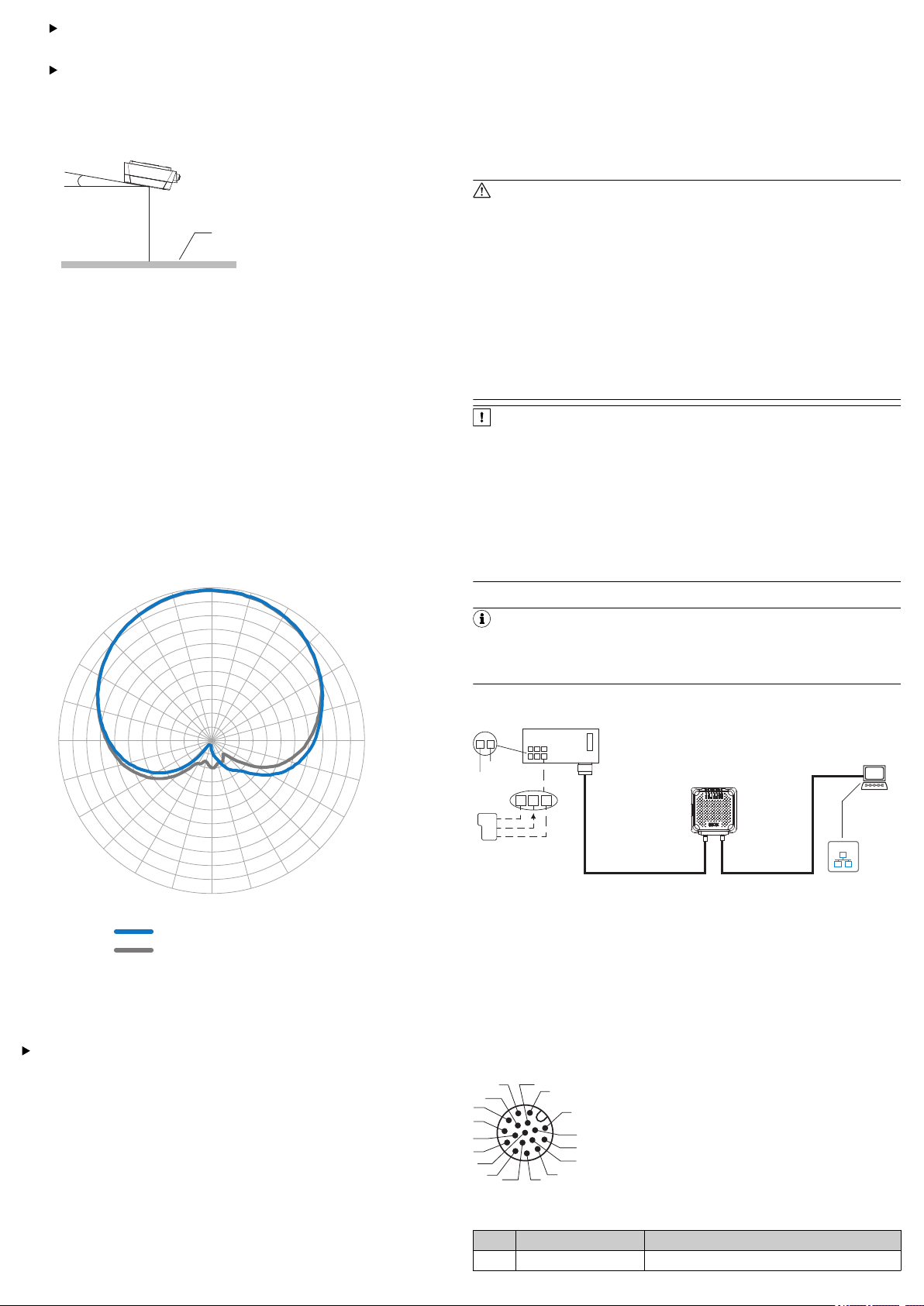
Sensing range of the reading and writing field
The UHF field of the internal antenna is influenced by its environment, making it
impossible to provide a “clear” demarcation of the sensing range. Application-spe‐
cific reflections can result in both overreaches and “holes”. In addition to the read
results, the RFU620 can also output diagnostic data that provide an indication of
the write and read quality. This data can be used to achieve optimum read results
when setting up the system.
The quality of the transponder and the material of the object also determine the
sensing range. The quality of the transponder is determined by the antenna gain,
the integrated transponder chip and the related sensitivity, and the reflected
energy.
The radiation pattern shown here for the internal antenna of the RFU620 was
obtained in a reproducible environment (absorber chamber) for illustrative pur‐
poses. It may therefore only have limited applicability to your specific application.
•
Wire cross-sections in the supply cable from the user’s power system must
be designed in accordance with the applicable national standards.
•
Only connect the device to the permitted supply voltage, see Technical data
(excerpt), page 6.
•
If the supply voltage is not supplied via the optional CDB620 connection
module, the RFU620 must be protected by a separate 0.8 A slow-blow fuse
at the start of the supply circuit.
•
All circuits connected to the device must be designed as SELV circuits. The
voltage supply or power supply unit must satisfy SELV requirements in accor‐
dance with the currently applicable EN 60950-1. (SELV = Safety Extra Low
Voltage).
WARNING
Risk of injury and damage caused by electrical current!
The device is designed for operation in a system with proficient grounding of
all connected devices and mounting surfaces to the same ground potential.
Due to equipotential bonding currents between the device and other
grounded devices in the system, incorrect grounding of the RFU620 can
charge the metal housing to a dangerous voltage, cause malfunction and
destruction of devices as well as damage to the cable shielding through heat‐
ing, and thus cause cable fires.
•
Ensure that the ground potential is the same at all grounding points.
•
If the cable insulation is damaged, disconnect the voltage supply imme‐
diately and have the damage repaired.
•
For measures for eliminating hazards, see the “Electrical installation”
chapter in the RFU62x RFID read/write device (UHF) operating instruc‐
tions on the product page on the Internet at www.sick.com/RFU62x
NOTICE
Risk of damage to the device due to possible short-circuit!
The supply voltage input for the device is designed with internal circuit protec‐
tion to provide reverse polarity protection. The internal functional earth, which
also corresponds to the negative pole of the supply voltage for the device, is
connected directly to the metal housing of the device due to reasons relating
to high frequency.
If the supply voltage is polarity-reversed, this will not cause any damage pro‐
vided that the following conditions are met for the device:
The device is not connected in an electrically conductive manner, either via
other cables or via its housing, to other peripheral devices which use the
same reference potential.
4.1 Connecting the RFU620
NOTE
The USB interface of the device is used in industrial environments only as a
service interface for temporary use (e.g. for configuration, troubleshooting).
Permanent use in real operation of the system as a host interface is not
intended.
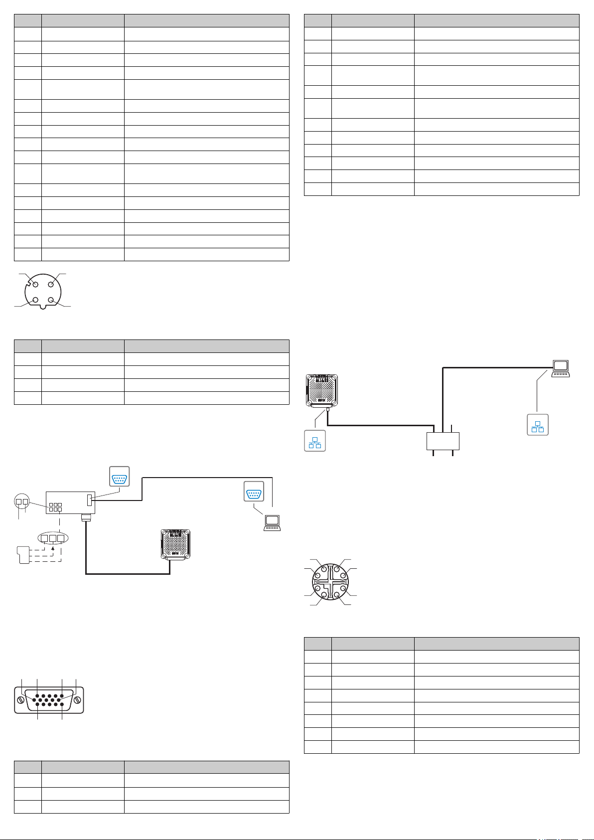
RFU620-101 xx: Ethernet variant
Figure 3: Commissioning: Electrical connection block diagram of the
RFU62 x-101 xx together with the optional connection module
1
2
3
4
5
6
Trigger sensor (read cycle)
Supply voltage V
CDB620, CDB650-204 or CDM420 connection module
S
Configuration, diagnosis, transponder access or display of read
results
Adapter cable (male connector, M12, 4-pin, D-coded / male connec‐
tor, RJ-45, 8-pin)
For CDB620 and CDM420: Adapter cable (female connector, M12,
17-pin, A-coded / male connector, D-Sub-HD, 15-pin)
For CDB650-204: Connection cable 1:1 (female connector, M12, 17pin, A-coded / male connector, M12, 17-pin, A-coded)
Figure 2: Radiation pattern of the internal antenna of the RFU620 (typical): Mea‐
sured antenna gain in dBic at 866.5 MHz, RHCP (right-hand circularly polarized)
1
2
Horizontal plane (azimuth)
Elevation plane (vertical)
3.5 Mounting the CDB620 connection module
Mount the CDB620 connection module in the vicinity of the RFU620. When
using the serial data interfaces (RS-232), the recommended length of cable
between the devices is max. 5 m. Mount the CDB620 in such a way that the
device can be accessed at all times, see the CDB620 connection module
operating instructions.
4 Electrical installation
•
•
•
•
The electrical installation must only be performed by electrically qualified persons.
Standard safety requirements must be met when working on electrical systems.
Electrical connections between the RFU620 and other devices may only be
made or separated when there is no power to the system. Otherwise, there is
a risk of damaging the devices.
When using connecting or extension cables with an open end, make sure
that bare wire ends are not touching (risk of short-circuit when the supply
voltage is switched on). Wires must be appropriately insulated from each
other.
8015928/10XX/2019-03-22/en RFU62x | SICK 2
Figure 4: Male connector, M12, 17-pin, A-coding
Pin assignment of the “Power/Serial data/CAN/I/O” connection (M12)
Pin Signal Function
1 GND Ground
Page 3
Pin Signal Function
1
43
2
Connection
module
SerialSerial
SOPAS ETSOPAS ET
"Power/Serial Data/Aux/CAN/I/O"
(Aux 1, Host 1)
...
...
1
2
V
S
GND
PC
RFU62x-
104xx
"Serial RS-232" (Aux 1)
Cable 4
5
11 10 12
Trigger
sensor
SGND
Sens 1
V
S
1
Out
GND
V
S
SerialSerial
2
3
Configuration
Diagnostics
Transponder
access
Reading result
6 1 105
11 15
Configuration
Diagnostics
Transponder
access
Reading result
SOPAS ETSOPAS ET
PC
"Ethernet (AUX 1)"
EthernetEthernet
EthernetEthernet
PoE Switch
(Endspan)
...
DC 48 V/57 V
PSE
**)
PD
*)
RFU62x-
105xx
*) PD = Powered Devices 4 **) PSE = Power Sourcing Equipment 3
"Ethernet"
Cable 1
2
"Ethernet (Aux 1/Host 1)/Power"
1
7
2
6
54
3
8
2 V
S
Supply voltage
3 CAN L CAN bus (IN/OUT)
4 CAN H CAN bus (IN/OUT)
5 TD+ (RS-422/485), Host Host interface (sender+)
6 TD– (RS-422/485), Host
TxD (RS-232), Host
Host interface (sender-)
7 TxD (RS-232), Aux Aux interface (sender)
8 RxD (RS-232), Aux Aux interface (receiver)
9 SensGND Switching input ground
10 Sensor 1 Digital switching input 1
11 RD+ (RS-422/485), Host Host interface (receiver+)
12 RD– (RS-422/485), Host
RxD (RS-232), Host
Host interface (receiver–)
13 Result 1 Digital switching output 1
14 Result 2 Digital switching output 2
15 Sensor 2 Digital switching input 2
16 N.c. –
17 N.c. –
– – Screen
Figure 5: M12 female connector, 4-pin, D-coded
Pin assignment of the “Ethernet” connection
Pin Signal Function
1 TD+ Sender+
2 RD+ Receiver+
3 TD– Sender–
4 RD– Receiver–
1. Connect the communication interface (e.g., Ethernet) of the RFU620 directly
to the PC.
2. Connect the 17-pin M12 male connector (Power/Serial Data/CAN/I/0) via a
suitable cable (e.g. no. 2055419, 2 m) to the 15-pin D-Sub-HD female con‐
nector of the CDB620.
RFU620-104xx (serial variant)
Pin Signal Function
4 Sensor 2 Digital switching input 2
5 GND Ground
6 RD+ (RS-422/485), Host Host interface (receiver+)
7 RD– (RS-422/485), Host
RxD (RS-232), Host
Host interface (receiver–)
8 TD+ (RS-422/485), Host Host interface (sender+)
9 TD– (RS-422/485), Host
TxD (RS-232), Host
Host interface (sender-)
10 CAN H CAN bus (IN/OUT)
11 CAN L CAN bus (IN/OUT)
12 Result 1 Digital switching output 1
13 Result 2 Digital switching output 2
14 Sensor 1 Digital switching input 1
15 SensGND Switching input ground
The pin assignment also corresponds to the D-Sub-HD male connector of the
adapter cable (female connector, M12, 17-pin, A-coded / male connector, D-SubHD, 15-pin)
1. Connect the 15-pin D-Sub-HD male connector of the RFU620-104xx con‐
necting cable to the corresponding female connector on the CDB620. In
order to maintain enclosure rating IP65 for the connecting cable of the
device when using an optional extension cable (e.g. no. 2043413, 2 m), use
the optional rubber seal (no. 4038847) between the male connector and the
female connector of the 15-pin D-Sub-HD plug connector and screw the plug
connector in place.
2. Connect the serial Aux interface (RS-232) of the RFU620-104xx to the PC. To
do so, connect the internal 9-pin D-Sub “Aux” male connector of the
CDB620 with a null-modem cable (e.g. no. 2014054, 2 m) to the PC (9-pin
D-Sub male connector). If the PC does not have an RS-232 interface, use an
additional suitable adapter cable with integrated RS-232 on the USB trans‐
ducer (e.g. no. 6042499, 1.5 m).
RFU620-105 xx (PoE version)
Figure 8: Commissioning: Electrical connection block diagram of the
RFU620-105 xx
1
Adapter cable (male connector, M12, 8-pin, X-coded / male connector,
RJ-45, 8-pin)
2
Configuration, diagnosis, transponder access or display of read
results
3
4
PSE = Energy source
PD = Energy consumer
Figure 6: Commissioning: Electrical connection block diagram of the
RFU620-104 xx with optional connection module
1
2
3
4
Trigger sensor (read cycle)
Supply voltage V
CDB620 or CDM420 connection module
S
Null modem cable (female connector, D-Sub, 9-pin / female connec‐
tor, D-Sub, 9-pin), crossed TxD and RxD
5
Configuration, diagnosis, transponder access or display of read
results
Figure 9: Female connector, M12, 8-pin, X-coded
Pin assignment of the “PoE” connection
Pin Signal Function
1 TD+ Sender+
2 TD– Sender–
3 RD+ Receiver+
4 RD– Receiver–
5 PoE– Supply voltage-
6 PoE– Supply voltage-
7 PoE+ Supply voltage+
8 PoE+ Supply voltage+
Connect the 8-pin M12 female connector via a suitable cable (e.g. no.
b
6049728, 2 m) to the PoE switch.
Figure 7: Male connector, D-Sub-HD, 15-pin
Pin assignment of the “Power/Serial data/CAN/I/O” connection (D-Sub-HD)
Pin Signal Function
1 V
2 RxD (RS-232), Aux Aux interface (receiver)
3 TxD (RS-232), Aux Aux interface (sender)
8015928/10XX/2019-03-22/en RFU62x | SICK 3
S
Supply voltage
Page 4

General information for all variants
1. Only RFU620-101xx and RFU620-104xx: If necessary, connect a trigger for
read cycles, e.g. a photoelectric sensor, to the “Sens” switching input of the
CDB620, see chapter “Electrical information” in the RFU62x RFID read/write
device (UHF) operating instructions.
2. Supply the RFU620 with voltage.
°
RFU620-101 xx: DC 10 V … 30 V
When using –25 °C to –40 °C: DC 20 V … 30 V
°
RFU620-104 xx: DC 10 V … 30 V
°
✓ After successful initialization, the “Device Ready” LED lights up green.
3. Turn on the PC and start Windows.
Block diagram of all interfaces of the RFU62 x-101 xx together with the optional
connection module: A
RFU620-105 xx: DC 48 V/57 V in accordance with PoE technology.
NOTE
For an overview of all interfaces and connection options for the
RFU620-104xx and RFU620-105xx, see the RFID read/write device (UHF)
operating instructions.
5 Commissioning and configuration with PC (Windows)
Adjustment of the device parameters to the application as well as diagnostics in
the event of malfunctions is undertaken by default with the SOPAS ET configura‐
tion software.
5.1 Installing and starting the configuration software
1. Download and install the latest version of the SOPAS ET configuration soft‐
ware as well as the current device description files (*.sdd): www.sick.com/
SOPAS_ET. In this case, select the “Complete” option as suggested by the
installation wizard. Administrator rights may be required on the PC to install
the software.
2. Start the “SOPAS ET” program option after completing the installation. Path:
Start > Programs > SICK > SOPAS ET Engineering Tool > SOPAS.
3. Establish communication between SOPAS ET and device with the automati‐
cally launching wizard. To do so, select the RFU620 under the devices avail‐
able depending on the connected communication interface, e.g. in the Ether‐
net (default Ethernet address: IP address: 192.168.0.1, subnet mask:
255.255.255.0). SOPAS ET establishes communication with the device and
loads the associated device description file. The Quickstart tab opens.
5.2 Detecting a transponder in Quickstart mode
1. Bring one or more standards-compliant UHF transponders into the working
range of the internal antenna of the device. The UII/EPC of the individual
transponders must be differentiated so that several transponders can be
detected.
2. Click the Start button on the Quickstart tab of SOPAS ET. SOPAS ET generates
an automated read cycle and lists the detected transponders one after
another in the Quickstart window.
5.3 Accessing the data on a transponder
1. In order to access the memory area of a transponder, click the Stop button in
Quickstart.
2. Highlight the desired transponder (click it with the mouse).
3. Click the Transponder Access button. The Transponder Management Access tab dis‐
plays the content of the selected transponder.
Figure 11: Transponder Access SOPAS ET display window
NOTE
The TID (tag identifier) of the transponder cannot be changed.
5.4 Continuing the configuration
1. Under SOPAS ET in the left-hand navigation tree, edit the required tabs for
the application using the additional entries under Parameters.These include
antenna configuration, performance optimization, data preprocessing,
transponder processing, object trigger control (e.g., via “Sensor 1” switching
input), data processing and output, data output interface(s), function of the
switching inputs and outputs, and the possible use of an optional microSD
memory card.
2. Set the transmitting power for the internal antenna using sliders on the
Antenna Configuration tab.
°
Regional permissible values for the antenna, see Device overview,
page 7.
°
RFU620 transmitting power default: 15 dBm (30 mW)
Figure 10: SOPAS ET display of the detected transponders in the Quickstart win‐
dow
Feedback about transponder detection in the UHF field
In Quickstart mode, the default signals of the process feedback LEDs indicate
whether a UHF field is present and transponders have been detected. The
process feedback LEDs 5 are located in the four corners of the antenna cover
and light up blue in this case.
Process feedback LEDs
PF LEDs Status Status
At half brightness
Lights ON UHF field present
At full brightness
Flashing Flashing slowly (f = 1.25 Hz) 1 transponder in field
Flashing Flashing quickly (f = 2.5 Hz) 2 transponders in field
Flashing Flashing faster (f = 5 Hz) More than 2 transponders in
NOTE
The automated triggering in Quickstart mode is intended for (initial) commis‐
sioning and not for permanent use when operating the device under real con‐
ditions.
8015928/10XX/2019-03-22/en RFU62x | SICK 4
field
3. Test and, if necessary, modify the settings made when operating the system
5.5 Completing the configuration
b
Figure 12: SOPAS ET: Example setting for the internal antenna
under real conditions.
Permanently save the entire configuration once it has been successfully
tested:
°
Parameter set in the device: Click the button
°
Configuration file on the PC: Click the button .
.
Page 5

6 Device description
Ready
ResultRFData
CAN
LNK/ACT
Micro-SD
Micro-SD
ResultRFData
CAN
LNK/ACT
Ready
100°
34.4
(1.35)
20.1
(0.79)
20.1
(0.79)
20.1
(0.79)
50 (1.97)
25
(0.98)
25
(0.98)
130.8 (5.15)
130.8 (5.15)
6 x 7.7 (0.30)
137.4 (5.41)
54 (2.13)
18.1
(0.71)
55.3
(2.18)
7
(0.28)
30
(1.18)
25.5
(1.00)
71.9 (2.83)
76.7 (3.02)
71.9
(2.83)
71.9
(2.83)
76.9
(3.03)
69.7
(2.74)
1 2
3
4
5
6
7
8
9
ß à
á
â
ã
113.9 (4.48)
103.3 (4.07)
116 (4.57)
RFU620-101xx
RFU620-105xx
RFU620-104xx
RFU620-101xx
RFU620-105xx
RFU620-104xx
Ready
LNK/ACT
Micro-SD
RF
CAN
Data
Result
3 2
1
6.1 Device layout
Advertisement LED Color Status
LNK/ACT Lights up Green Data traffic via Ethernet
Micro-SD Lights up Green microSD card inserted and ready for operation. In
Lights up Red microSD card inserted; however, it cannot be
Lights up Yellow A function is star ted via SOPAS ET which requires
1)
RFU620-105 xx (PoE variant): LED without function
this state, the device can either read data from
the card or write data to the card.
If the LED lights up, however, this does not indi‐
cate that the device is accessing the card!
read or is defective
a memory card. The microSD card is not ready for
operation, however (e.g. not plugged in, contacts
contaminated or without free storage space for
writing).
Additional indicators for ambient temperatures below –40 °C/-25 °C
Advertisement LED Color Status
Ready Flashing Yellow Flashing, frequency 1 Hz.
Flashing Green Flashing, frequency 1 Hz.
The device is not ready for use:
RFU62x-101xx: Interior temperature of the
device –40 °C.
RFU62x-104xx/-105xx: Interior temperature of
the device under –25 °C.
Warming up phase:
RFU62x-101xx: Interior temperature of the
device between –40 °C and –20 °C. The device
starts up regular operation after a maximum of 5
min.
RFU62x-104xx/-105xx: Interior temperature of
the device between –25 °C and –20 °C. The
device starts regular operation again after about
1 min.
6.3 microSD memory card (optional accessory)
Function
The device can execute the following functions on the plug-in memory card:
•
Automated, additional storage of the internal parameter set to an external
storage medium (cloning function), if available. This is done in the framework
of the recommended safety concept for the 4Dpro device parameter sets.
The function is triggered by saving the internal parameter set with the “per‐
manent” option. The function is used, among other things, to conveniently
transmit the parameter set to an exchange unit of the same type in the event
of an error. Optional external media include a memory card which can be
Figure 13: Dimensional drawing of the RFU620 (all variants), all dimensions in
mm or inch
1
“Power/Serial data/CAN/I/O” connection (male connector, M12, 17pin, A-coded)
2
3
4
5
6
7
8
9
ß
à
á
â
ã
6.2 Status displays
“Ethernet” connection (female connector, M12, 4-pin, D-coded)
“PoE” connection (female connector, M12, 8-pin, X-coded)
“Power/Serial data/CAN/I/O” connection (male connector, D-Sub-HD,
15-pin), cable 0.9 m
4 x LED, multi-colored (process feedback)
7 x LED, multi-colored (status indicator)
Cover with internal antenna
2 x screw (Torx T8), captive, for side cover
Side cover open
“USB” connection (female connector, 5-pin, type Micro-B) interface for
temporary use (service)
Slot for microSD memory card
4 x M5 blind tapped hole, 9 mm deep, for alternative mounting of the
device
Pressure compensation valve (ventilation element)
2 x M6 blind tapped hole, 6 mm deep, for mounting the device
Status displays
Advertisement LED Color Status
Ready Lights up Green Device ready
Lights up Red Hardware error
Flashing Green Flashing cyclically 4 x red, 1 x green in PROFINET
Flashing Red
operation (single port): Trying to establish a con‐
nection to a PLC (IO controller) or loss of connec‐
tion during operation
Result Lights up Green Read or write successful
RF Lights up Green UHF field activated
Lights up Red Internal antenna fault / HF part
Data Lights up Green Data output via host interface
CAN Lights up Yellow Data traffic via CAN bus (CAN Rx)
8015928/10XX/2019-03-22/en RFU62x | SICK 5
plugged into the device or the CMC600 parameter storage module, which
can be used in the optional connection module, e.g., CDB620 or
CDM420-0001.
•
Continuous recording of diagnostic read data after the first manual start,
e.g., via SOPAS ET. Recording is resumed after a device restart when the
function is set permanently.
The first time a parameter set is stored, we recommend that an empty memory
card is used (if necessary, check and delete the contents of the card on the PC
using a card reader).
The memory card is not included with delivery.
Only use types approved by SICK to ensure reliable function of the memory card,
see www.sick.com/RFU62x. The memory card has no write protection that can be
activated.
Inserting the memory card
NOTICE
To avoid damaging the memory card, make sure there is no power to the
device when you insert or remove it.
The card slot can be accessed on the device behind the plastic foil, see Device
description, page 5.
Maintaining enclosure rating IP65 or IP67: see Safety information, page 1.
1. Switch off the supply voltage to the device.
2. Loosen both screws on the cover.
3. Carefully fold up the cover.
4. Making sure it is in the correct position (with the contacts pointing to the
front and down – see the symbol on the device), insert the memory card into
the card slot until it locks into place.
5. Screw the cover back on. Recommended tightening torque for the cover
screws: 60 Ncm ± 5 Ncm.
6. Switch the supply voltage for the device back on.
Figure 14: USB connection and slot for microSD memory card
1
2
3
Slot for microSD memory card
USB port (female connector, Micro-B, 5-pin)
2 x screw, Torx T8
Page 6

7. Once it is switched on, the device automatically detects the presence of a
memory card and, depending on the card’s content, behaves as follows:
°
If the card is empty or if it contains a parameter set that cannot be
interpreted by the device, the device saves its currently valid internal
parameter set to the card (provided there is sufficient storage space)
and starts with the internal parameter set.
°
If the card contains a parameter set that can be interpreted by the
device, the device overwrites the currently valid internal parameter set
with this external parameter set.
The goal is for the internal parameter set and the parameter set saved
externally to always be identical.
NOTICE
Possible data loss or irreparable damage to the memory card!
The device does not signal access to the card.
•
Only use memory card when the device power is off.
•
Do not remove the memory card or turn off the supply voltage if there
are parameter values in the device that have been changed to the “per‐
manent” option or functions have been started that access the memory
card with the SOPAS ET configuration software (e.g. logging of data ).
•
To remove the memory card safely during operation, select the Remove
card function under Analysis/SD card and wait for SOPAS ET to provide
confirmation.
7 Maintenance and care
The device does not contain any components that require maintenance.
To maintain the full read and write rate, gently clean the antenna hood (plas‐
tic) in case of soiling (e.g. metal dust) with a soft, damp cloth (mild cleaning
agent).
8 Transport and storage
Transport and store the device in the original packaging, with protective plugs and
caps completely screwed-on. Do not store outdoors. To ensure that any residual
moisture present can escape, do not store the device in airtight containers. Do
not expose to any aggressive substances.
Storage conditions: Dry, dust-free, no direct sunlight, as little vibration as possi‐
ble, storage temperature –40 °C to +70 °C, relative humidity max. 90% (non-con‐
densing).
Type RFU620-10xxx
EtherCAT® Only RFU620-101xx / RFU620-104xx
Digital switching inputs Only RFU620-101xx / RFU620-104xx
Digital switching outputs Only RFU620-101xx / RFU620-104xx
Electrical connections
Host over external CDF600-0300 module (Gateway mode)
2 x physical, 2 x additional external via optional CMC600 mod‐
ule in the CDB/CDM connection module. Vin = max. 30 V, Iin =
max. 5 mA. Opto-decoupled, reverse polarity protected,
adjustable debounce time
2 x physical, 2 x additional external via optional CMC600 mod‐
ule in the CDB/CDM connection module. V
≤ 100 mA (typical). Short-circuit protected, temperature pro‐
tected, not electrically isolated from the supply voltage
= Vs – 1.5 V, I
out
RFU620-101xx
•
1 x male connector, M12, 17-pin, A-coded
•
1 x female connectors, M12, 4-pin, D-coded
•
1 x female connector, USB, 5-pin, Micro B type
RFU620-104xx
•
1 x cable, 0.9 m with male connector, D-Sub-HD, 15-pin
•
1 x female connector, USB, 5-pin, Micro B type
RFU620-105xx
•
1 x female connectors, M12, 8-pin, X-coded
•
1 x female connector, USB, 5-pin, Micro B type
Optical indicators
•
7 x RGB LED (status indicators) on front top/side
•
4 x RGB LED (process feedback) in the corners of the
antenna cover, function/color can be adjusted via SOPAS
ET
Parametric data backup Optional: Via plug-in microSD card or over external module
Supply voltage U
V
CMC600 in the CDB/CDM connection module
All devices: SELV in accordance with currently applicable
EN 60950-1, LPS (EN 60950-1) or NEC Class 2 (UL1310).
RFU620-101xx
•
Without use of integrated heating: DC 10 V ... 30 V
•
With use of integrated heating (–25 °C ... –40 °C):
DC 20 V ... 30 V
RFU620-104xx
•
DC 10 V ... 30 V
out
RFU620-105xx
•
9 Repairs
Repair work on the device may only be performed by qualified and authorized ser‐
vice personnel from SICK AG.
Power consumption
DC 48 V / 57 V according to PoE technology
Operation
•
All variants: typically 8 W (with unloaded switching out‐
puts and full transmitting power)
10 Disassembly and disposal
Any device which can no longer be used must be disposed of in an environmen‐
tally friendly manner in accordance with the applicable country-specific waste dis‐
posal regulations. As it is categorized as electronic waste, the device must never
be disposed of with household waste!
11 Technical data (excerpt)
Technical specifications
Type RFU620-10xxx
Regional assignment Depending on type: see Device overview, page 7
Firmware version Depending on type: see Device overview, page 7
Carrier frequency Depending on type: see Device overview, page 7
Transmitting power 1 internal antenna, adjustable: depending on type, see Device
Internal antenna
Air interface protocol ISO/IEC 18000-6 C
Sensing range Typically up to 1 m (depending on the transponder and ambient
Serial RS-232/422/485 Only RFU620-101xx / RFU620-104xx
Serial RS-232 Only RFU620-101xx / RFU620-104xx
2)
USB
CAN Only RFU620-101xx / RFU620-104xx
Ethernet 10/100 Mbit/s
PROFIBUS Only RFU620-101xx / RFU620-104xx
PROFINET (line topology) Only RFU620-101xx / RFU620-104xx
8015928/10XX/2019-03-22/en RFU62x | SICK 6
description, page 5
•
Circularly polarized
•
Axis behavior: typically 2 dB (ETSI), 3 dB (FCC)
•
Aperture angle: 100° (ETSI), 100° (FCC)
•
Front-to-back ratio: typically > 7 dB (ETSI), > 7 dB (FCC)
EPCglobal UHF Class 1 Generation 2
conditions)
HOST 1 (0.3 kBd to 115.2 kBd) for data output
Aux 1 (57.6 kBd) for servicing
Aux 3 (USB 2.0) for servicing
1)
1)
CAN (CANopen®), 20 KBit/s ... 1 MBit/s. Max. bus length 30 m
Only RFU620-101xx / RFU620-105xx
•
Host 2 (TCP/IP, EtherNet/IP, PROFINET Single Port) for
data output
•
Aux 2 (TCP/IP) for servicing
•
Services: DHCP, NTP, HTTP
1)
Host over external CDF600-21xx module
Host over external CDF600-2200 module
Housing / Weight Aluminum/approx. 780 g
Safety EN 60950-1: 2006-04/A11: 2009-03/ A1: 2010-03/A12:
Electrical protection class III (EN 61140: 2006-08)
Enclosure rating According to EN 60529: 1991-10/A2: 2000-02
Radio equipment approval See model-specific online data sheet
EMC EN 301489-3
MTBF 23 years
Vibration resistance EN 60068-2-6: 2008-02
Shock resistance EN 60068-2-27: 2009-05
Ambient temperature range
Relative humidity 0 % ... 90 %, non-condensing
Conformity CE, UL
Clock NTP net work time protocol, no internal clock
1)
For example: configuration, diagnosis, transponder access or display of the read results.
2)
Interface only for temporary use
3)
Continuous operation at an ambient operating temperature of +50 °C.
4)
Only UL certified if the type label contains the UL logo.
For further technical specifications, see the online data sheet on the product page
on the Internet at: www.sick.com/RFU62x.
Regulatory notes
Europe: Simplified EU declaration of conformity
•
RFU620-101 xx: Additional for heating (–25 °C ...
–40 °C): Maximum 12 W
Readiness (standby)
•
All: Typically 3 W
2011-02
RFU620-101xx / RFU620-105xx
•
IP67
RFU620-104xx
•
IP65
3)
RFU620-101xx
•
Operation: –40 °C ... +50 °C
•
Storage: –40 °C ... +70 °C
RFU620-104xx / RFU620-105xx
•
Operation: –25 °C ... +50 °C
•
Storage: –40 °C ... +70 °C
Page 7

SICK AG hereby declares that the RFU620-10xxx radio equipment complies with
the 2014/53/EU directive. The complete text of the EU declaration of conformity
is available at the following web address: www.sick.com/RFU62x.
12 Device overview
RFU62x-101xx: Device overview
Regional
assign‐
ment
Europe/
South
Africa
USA/
Canada/
Mexico/
Ecuador
USA/
Canada/
Mexico
Australia V2.02 920.25 MHz ...
India V1.60 865,7 MHz ...
Brazil V1.50 902,75 MHz ...
China/
Thailand
Japan V1.42 916.8 MHz ...
Russia V1.71 866.3 MHz ...
Korea V1.64 917.3 MHz ...
New
Zealand
Indonesia 2.0.0R 923.25 MHZ
Malaysia V1.63 919.25 MHz ...
1)
2)
Firmwa
Carrier fre‐
re from
quency
version
V1.40 865,7 MHz ...
867,5 MHz
V1.40 902,75 MHz ...
927,25 MHz
925.75 MHz
866.9 MHz
907.25 MHz
915.25 MHz ...
927,25 MHz
V1.50 920.625 MHz
...
924.375 MHz
920.4 MHz
867,5 MHz
920.3 MHz
V1.71 920,25 MHz ...
927,25 MHz
…
924.75 MHZ
922.75 MHz
ERP = equivalent radiated power.
EIRP = equivalent isotropic radiated power.
Transmitting
power of the
internal
antenna
Max.
250 mW
(ERP 1))
Max.
320 mW
(EIRP 2))
Max.
320 mW
(EIRP 2))
Max.
250 mW
(ERP 1))
Max.
320 mW
(EIRP 2))
Max.
200 mW
(ERP 1))
Max.
320 mW
(EIRP 2))
Max.
200 mW
(ERP 1))
Max.
320 mW
(EIRP 2))
Max.
320 mW
(EIRP 2))
Max.
200 mW
(ERP 1))
Max.
200 mW
(ERP 1))
Device
type
RFU62010100
RFU62010400
RFU62010500
RFU62010101
RFU62010401
RFU62010501
RFU62010102
RFU62010103
RFU62010503
RFU62010104
RFU62010504
RFU62010105
RFU62010505
RFU62010107
RFU62010507
RFU62010108
RFU62010508
RFU62010110
RFU62010510
RFU62010111
RFU62010112
RFU62010114
RFU62010514
Part no. Supplied
1062599 English
1062600
Quickstart
(Part no.)
(8015928),
German
(8015927)
1062601
1062602 English
(8015928),
Spanish
(8018883)
1062603
1062604
1101700 English
1091355 English
(8015928)
(8015928)
1069453
1069677 English
1070407
1068728 English
1077860
1068727 English
1083976
1094605 English
1088871
1086439 English
1083557
1084997 English
1092037 English
1096414 English
(8015928),
Portuguese
(8017353)
(8015928),
Chinese
(8017351),
Thai
(8021903)
(8015928),
Japanese
(8017352)
(8015928),
Russian
(8021504)
(8015928),
Korean
(8020185)
(8015928)
(8015928)
(8015928)
1077863
12.1 Operational restrictions
NOTICE
Operational restric tions!
When delivered, the frequency band of the RFU620 is configured in such a
way that it can be operated in the following assigned regions (depending on
the model) without interfering with protected frequencies (such as mobile
communications):
•
RFU620-10x00 (Europe/South Africa)
•
RFU620-10101 (USA/Canada/Mexico/Ecuador)
•
RFU620-10401/-10501 (USA/Canada/Mexico)
•
RFU620-10x02 (Australia)
•
RFU620-10x03 (India)
•
RFU620-10x04 (Brazil)
•
RFU620-10x05 (China/Thailand)
•
RFU620-10x07 (Japan)
•
RFU620-10x08 (Russia)
•
RFU620-10x10 (Korea)
•
RFU620-10x11 (New Zealand)
•
RFU620-10x12 (Indonesia)
•
RFU620-10x14 (Malaysia)
Operating the same RFU620 in other regions can interfere with protected fre‐
quencies.
Only use the RFU620 in the region for which it has been approved.
b
When reselling the RFU620, inform the buyer of the regional assign‐
b
ment.
France
The RFU620 must not be operated within a 20 km radius of 13 military zones.
Lithuania
There may be restrictions in Lithuania (extent not currently known).
Russia
Only licensed operation is possible in Russia.
USA
(1) This device complies with part 15 of the FCC Rules. Operation is subject to the
following two conditions:
(1) This device may not cause harmful interference, and (2) this device must
accept any interference received, including interference that may cause undesired
operation.
(2) Changes or modifications not expressly approved by the party responsible for
compliance could void the user’s authority to operate the equipment.
(3) Note: This equipment has been tested and found to comply with the limits for
a Class A digital device, pursuant to part 15 of the FCC Rules. These limits are
designed to provide reasonable protection against harmful interference when the
equipment is operated in a commercial environment. This equipment generates,
uses, and can radiate radio frequency energy and, if not installed and used in
accordance with the instruction manual, may cause harmful interference to radio
communications. Operation of this equipment in a residential area is likely to
cause harmful interference in which case the user will be required to correct the
interference at his own expense.
(4) To comply with FCC part 15 rules in the United States, the system must be pro‐
fessionally installed to ensure compliance with the Part 15 certification.
(5) It is the responsibility of the operator and profes-sional installer to ensure that
only certified systems are deployed in the United States. The use of the system in
any other combination (such as co-located antennas transmitting the same infor‐
mation) is expressly forbidden.
(6) This device complies with the limit values defined by the FCC for radio radia‐
tion in an uncontrolled environment. The device must have a minimum distance
of 20 cm between the source of radiation and your body.
Canada
(1) This Class A digital apparatus complies with Canadian ICES-003.
(2) This device satisfies the Industry Canada CNR applicable to license-free radio
equipment. Use is permitted providing the two following conditions are met: (1)
The device must not cause any faults and (2) the user of the device must accept
any fault produced in the device, even if this may impair its function.
Mexico
(1) IFETEL note:
“Operation is subject to the following two conditions: (1) This device must not pro‐
duce any harmful faults and (2) this device must be able to withstand faults,
including faults that may cause unwanted operating behavior.”
Korea
(1) This equipment is Industrial (Class A) electromag-netic wave suitability equip‐
ment and seller or user should take notice of it, and this equipment is to be used
in the places except for home.
(2) That wireless equipment is likely to cause propa-gation interference, and so
can not be associated with lifesaving services.
Thailand
(1) This telecommunication equipment is in compliance with NBTC requirements.
(2) This radiocommunication equipment has the electromagnetic field strength in
compliance with the Safety Standard for the Use of Radiocommunication Equip‐
ment on Human Health announced by the National Telecommunications Commis‐
sion.
13 Sources for obtaining more information
Additional information about the device, its optional accessories, and fieldbus
modules can be found in electronic format on the following product pages on the
Internet at:
8015928/10XX/2019-03-22/en RFU62x | SICK 7
Page 8

13.1 RFU620 RFID read/write device
"Ethernet"
(Host 2)
"Ethernet"
(Aux 2)
"Ethernet"
Input 2 3
Input 1 4
Output 1 2
Output 2 1
RFU62x-
101xx
Connection
module
"Power/Serial Data/CAN/I/O"
(Aux 1, Host 1)
...
...
1
2
V
S
GND
HOST
V
S
EthernetEthernet
Cable å Cable ä
Reading result â
"Serial RS-232/RS-422/485" (Host 1) ã
á
5
6
USBUSB
"Serial RS-232" (Aux 1) 7
Cable 8
SOPAS ETSOPAS ET
PC
à
"USB" (Aux 3),
for temporary use only 9
Cable ß
Configuration
Diagnostics
Transponder
access
Reading result
Further data
processing
www.sick.com/RFU62x
•
Summary of type-specific technical data (online data sheet)
•
EU declaration of conformity
•
Dimensional drawing and 3D CAD dimension models in various electronic
formats
•
Compatible accessories (including transponders, cables, brackets, trigger
sensors)
•
RFU620 RFID read/write device (UHF) Quickstart in English (no. 8015928)
and German (no. 8015927), in other languages if required
•
RFU620 (UHF) RFID read/write device operating instructions
•
Ordering information, e.g. in the RFID product information in English
(no. 8016267) and German (no. 8016266)
•
Publications dealing with accessories
13.2 Function blocks
www.sick.com/RFU62x
•
Function blocks for communication between a SIMATIC controller (S7-300/
S7-400) and the device.
•
Function blocks for other controllers on request.
13.3 CDF600-21xx PROFIBUS fieldbus module
www.sick.com/CDF600-2
•
CDF600-21 xx PROFIBUS fieldbus module operating instructions in English
(no. 8015335) and German (no. 8015334), in other languages if required
13.4 CDF600-22xx PROFINET fieldbus module
www.sick.com/CDF600-2
•
CDF600-2200 PROFINET fieldbus module operating instructions (M12 vari‐
ant) in English (no. 8015922) and German (no. 8015921) as well as in other
languages, if applicable
13.5 CDF600-0300 EtherCAT fieldbus module®
www.sick.com/CDF600
•
CDF600-0300 EtherCAT® fieldbus module operating instructions in English
(no. 8013919) and German (no. 8013918), in other languages if required
13.6 Documents on request
•
Overview of command strings of the device
Support is also available from your sales partner: www.sick.com
13.7 Copyright notices
EtherCAT®
EtherCAT® is a registered trademark and patented technology, licensed by Beck‐
hoff Automation GmbH, Germany.
Open source programs
SICK uses open-source software in the device. This software is licensed by the
rights holders using the following licenses among others: the free licenses GNU
General Public License (GPL Version2, GPL Version3) and GNU Lesser General
Public License (LGPL), the MIT license, zLib license, and the licenses derived from
the BSD license.
This program is provided for general use, but WITHOUT ANY WARRANTY OF ANY
KIND. This warranty disclaimer also extends to the implicit assurance of mar‐
ketability or suitability of the program for a particular purpose.
More details can be found in the GNU General Public License.
View the complete license texts here: www.sick.com/licensetexts
Printed copies of the license texts are also available on request.
A
1
2
3
4
5
6
7
8
9
ß
à
á
â
ã
ä
å
Digital switching output 2, e.g., for connecting an LED
Digital switching output 1, e.g., for connecting an LED
Digital switching input 2, e.g., for connecting an incremental encoder
Digital switching input 1, e.g., for connecting a (read cycle) trigger sensor
Supply voltage V
CDB620, CDB650-204 or CDM420 connection module
S
Alternative to USB or Ethernet Aux port
Null modem cable (female connector, D-Sub, 9-pin / female connector, D-Sub, 9-pin), crossed TxD and RxD
USB, alternative to serial RS-232 or Ethernet Aux port. USB interface only for temporary use (servicing).
Adapter cable (male connector, USB, Micro-B type / male connector, USB, type A)
Configuration, diagnosis, transponder access or display of read results
Further data processing
Read result
Alternative to Ethernet host port
Adapter cable (male connector, M12, 4-pin, D-coded / male connector, RJ-45, 8-pin)
For CDB620 and CDM420: Adapter cable (female connector, M12, 17-pin, A-coded / male connector, D-Sub-HD, 15-pin)
For CDB650-204: Connection cable 1:1 (female connector, M12, 17-pin, A-coded / male connector, M12, 17-pin, A-coded)
8015928/10XX/2019-03-22/en RFU62x | SICK 8
 Loading...