

Page 1

8023832/15YN/2019-12-11
SICK AG
E
rwin-Sick
-Straße 1
D-79183 Waldkirch
www.sick.com
RFU61x
Q U I C K S T A R T e n
1 About this document
The purpose of this Quickstart is to allow you to commission the RFU610-106xx
RFID read/write device (UHF) quickly and easily and to achieve initial read results
with transponders.
The Quick Start Guide is valid for all the regional radio variants listed: see Device
overview, page 7.
In the following, the Quick Start Guide refers to the RFU610-106xx (UHF) RFID
read/write device simply as “device”. If variants are to be differentiated in the
regional assignment, the respective device name RFU610-106xx is specified (xx =
regional assignment).
The Quickstart describes the commissioning process for an application with an
RFU610-106xx in an ambient temperature range of 0 °C to +50 °C.
Commissioning is carried out as an example for the RFU610-10600 device vari‐
ant (Ethernet variant, Europe region and other countries if necessary, see Device
overview, page 7). The basis is the basic parameter setting of the device. The
optional GL6 photoelectric sensor is used as an example for the industrial-stan‐
dard read-cycle triggering of the device (part no. 1059241). The photoelectric sen‐
sor can be connected with the device as a trigger sensor. Additional trigger sen‐
sors can be found at www.sick.com.
All rights reserved. Subject to change without notice.
Supplementary documents
Information, such as application examples and downloads of associated docu‐
ments (e.g. operating instructions) and software, can be found on the SICK prod‐
uct page on the Internet at: www.sick.com/RFU61x. For an overview see Sources
for obtaining more information, page 7 in this Quick Start Guide.
More detailed information on mounting and electrically installing the device as a
stand-alone unit than provided in this Quickstart is available in the RFU61x RFID
read/write device (UHF) operating instructions. The operating instructions add the
following information to the Quick Start Guide:
•
Requirements and notes for mounting and electrical installation at operating
ambient temperatures below 0 °C
•
For applications in widely distributed systems: Notes on the suppression of
ground potential equalizing currents
2 Safety information
•
This chapter is dedicated to the safety of commissioning personnel and the
operator of the system in which the device is integrated.
•
Read this Quickstart carefully to familiarize yourself with the device and its
functions before commissioning the device. The Quickstart is considered a
part of the device and must be kept in an accessible location in the immedi‐
ate vicinity of the device at all times!
Electromagnetic radiation
WARNING
Health hazard as a result of high-frequency electromagnetic radiation!
The RFU610-10600 (Europa region and possibly other countries) is designed
for operation in accordance with ETSI EN 302208. During operation, the
human exposure regulations covered by EN 50364 must be observed.
•
Limit human exposure to electromagnetic fields. Suitable safety dis‐
tances must be maintained during both short-term and long-term work
in the radiation range of the integrated antenna. Minimum distances to
be maintained between the antenna and the human body during longterm transmission: 10 cm and maximum radiation power of the antenna
of 100 mW (20 dBm) as per ETSI.
The RFU610-10601 (USA region and possibly other countries) satisfies the
limit values of the FCC for exposure to radiation in an uncontrolled environ‐
ment.
•
During operation, a safety distance of at least 20 cm must be main‐
tained between the antenna and the human body.
Complete region assignment of the RFU610-106xx see Device overview,
page 7.
Conditions for specified enclosure rating
•
To ensure compliance with the IP67 enclosure rating of the device during
operation, the following requirements must be met. If these requirements
are not met, the device does not fulfill any specified enclosure rating.
°
The joint side cover for the USB interface and the memory card slot is
placed against the device and screwed on tight. Recommended tighten‐
ing torque for the cover screws: 30 Ncm ± 5 Ncm.
°
The cables plugged into the electrical M12 and M8 connections must
be screwed tight.
°
Any unused M12 and M8 connections must be sealed with screw-on
protective caps (for male connectors) or plugs (for female connectors)
as supplied.
°
Only operate the device without a cover for a short period while insert‐
ing or removing the memory card or temporarily using the USB inter‐
•
•
Standard IP technology
2.1 Intended use
The RFU61x RFID read/write device (UHF) is an intelligent ID sensor from the
RFU6xx product family. Version (working range): Short Range.
The stationary device automatically identifies wireless-based data cards
(transponders) on stationary and moving objects. The device also supports data
card management.
The compact read/write device has an (internal) antenna integrated in the hous‐
ing. The device processes the data of all standard passive transponders in accor‐
dance with ISO/IEC 18000-63 and EPCglobal UHF C1G2 in the regional UHF car‐
rier frequency range.
Intelligent process logic enables processing as a stand-alone solution. Network
operation is possible for coordinating trouble-free readings of devices at close
proximity to one another, but without a coordinating summary of the reading
results. The device sends the read results to a higher-level computer (e.g. PLC) via
its host interface. The computer coordinates further processing of the data in the
process.
The device receives corresponding commands for data card management (write,
read, etc.) via its host interface.
Device variants refer to the region assignment, see Device overview, page 7.
Intended use of the device also includes compliance with all information in this
Quickstart and the supplementary RFU61x RFID read/write device (UHF) operat‐
ing instructions.
face. During this time, protect the device against moisture and dust.
The type label on the lower side of the device contains a pressure equalizing
membrane attached in the middle. If the type label is damaged or removed,
the leak tightness of the device can no longer be guaranteed.
Opening the screws of the device housing will invalidate any warranty claims
against SICK AG. For further warranty provisions, see the General Terms and
Conditions of SICK AG, e.g. on the delivery note of the device.
NOTE
SICK uses standard IP technology in its products. The emphasis is
placed on availability of products and services.
SICK always assumes the following prerequisites:
•
The customer ensures the integrity and confidentiality of the data
and rights affected by its own use of the aforementioned products.
•
In all cases, the customer implements the appropriate security
measures, such as network separation, firewalls, virus protection,
and patch management.
NOTE
The device approval was granted for a specific region. The region assignment
cannot be changed.
•
Only use the device in the region and the country for which it has been
approved.
•
When reselling the device, inform the buyer of the fixed region assign‐
ment.
•
Should the device be passed on to a third party, these operating instruc‐
tions and the Quick Start Guide should be handed over with it.
•
For country-specific particulars to consider when operating the device,
see Operational restrictions, page 7.
8023832/15YN/2019-12-11/en RFU61x | SICK 1
Page 2
3 Device description
92 (
3.62
)
1
9
8
94 (
3.70
)
106.4 (
4.19
)
ReadyRFLink/Act
microSD
40 (
1.57
)
16
(
0.63
)
36 (
1.42
)
â
80 (
3.15
) 38 (
1.50
)
12
(
0.47
)
71 (
2.80
)
40 (
1.57
)
5
(
0.20
)
6.4
(
0.25
)
17.5
(
0.69
)
78.8 (
3.10
)
1 3 2
91°
3 (
0.12
)
11.5 (
0.45
)
9.5 (
0.37
)
2
1
4
3
2 3
4 5
ß
á à
6
7
17.5
(
0.69
)
RF
Ready
Link/Act
3.1 Device view
Advertisement LED Color Status
Lights up Red The memory card is inser ted.
However, the device cannot read data on the
memory card.
Possible causes:
•
The memory card does not contain any data
•
The content is not readable
•
The memory card is defective
Lights up Orange 1)A function is star ted with SOPAS ET which
1)
Prerequisite: In SOPAS ET, the “SD card required” function has been activated under the
“Service” user level.
requires a memory card for writing. However, the
memory card is not connected.
3.3 Memory card (optional accessory)
The device can execute the following functions on the plug-in microSD memory
card:
•
Cloning function: If a MicroSD memory card is present, the device automati‐
cally saves its internal parameter set on the memory card as well. This pro‐
cedure is carried out in the framework of the recommended storing concept
for the device parameter sets. Storing the internal parameter set with the
“permanent” option triggers the cloning function. The function is used,
among other things, to conveniently transfer the parameter set to an
replacement device of the same type in the event of a fault.
•
Data logging: The device continuously records read diagnosis data after the
first manual start, e.g. via SOPAS ET. If the function is permanently set, the
device automatically resumes recording after a restart.
NOTE
Recommendation:
Use an empty memory card to save a parameter set for the first time. If nec‐
essary, check the contents of the card on the PC using a card reader and
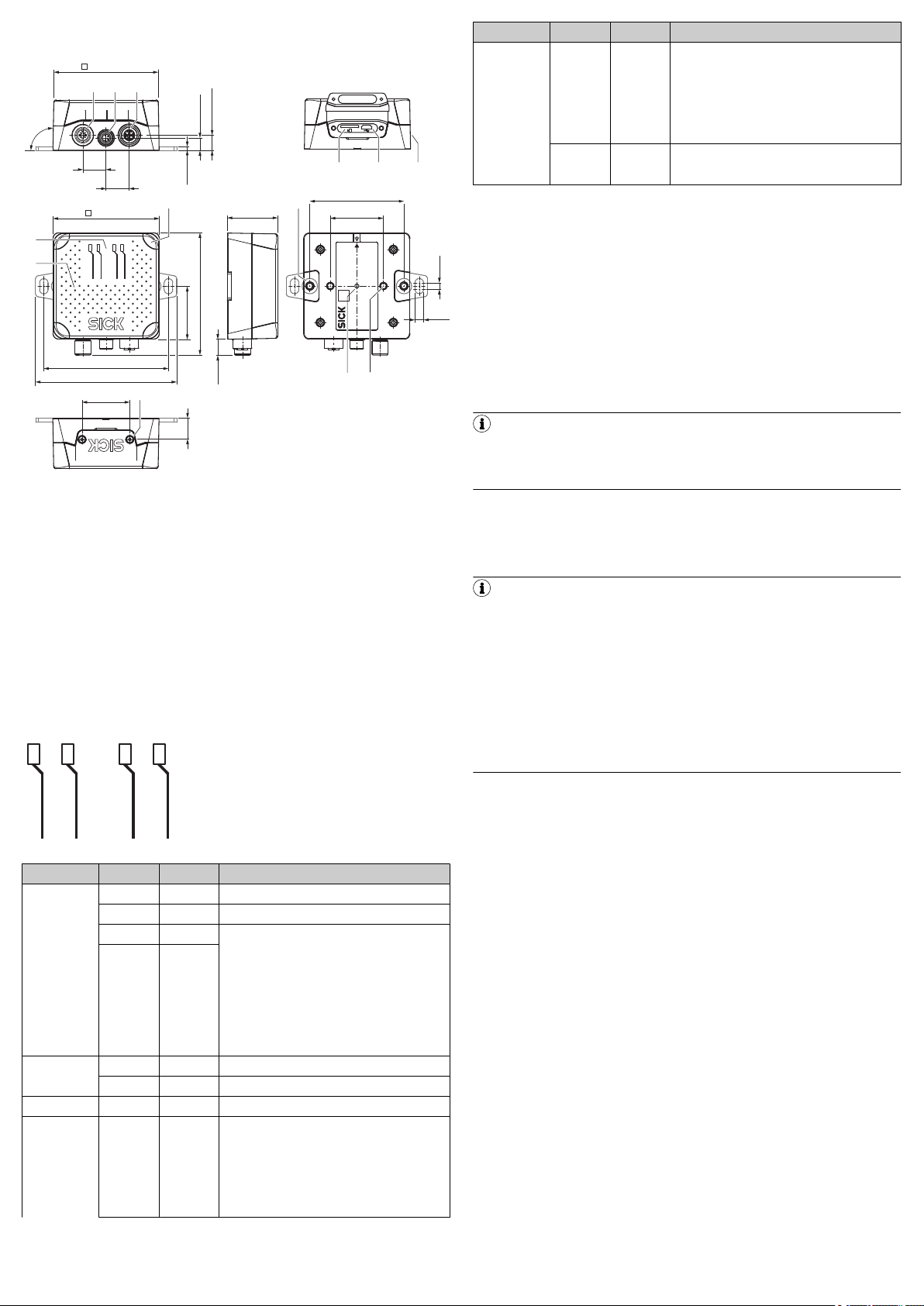
Figure 1: Dimensional drawing of the RFU610-106xx, unit: mm (inch), decimal
separator: period
1
2
3
4
5
Connection 1: Power (male connector, M12, 4-pin, A-coded)
Connection 3: Trigger (female connector, M8, 4-pin, coded)
Connection 2: PoE (female connector, M12, 8-pin, X-coded)
Slot for microSD memory card
“USB” connection (female connector, 5-pin, Micro B type). The USB
interface is only for temporary use as a service interface.
6
7
8
9
ß
Side type label
Optics cover with integrated antenna
4 x multi-colored LED (status)
4 x multi-color LED (process feedback)
2 x M5 threaded mounting holes, 6 mm deep, for attaching the
mounting straps
à
2 x M5 blind tapped holes, 7 mm deep, for alternative mounting of
the device
á
â
type label with integrated pressure compensation membrane
2 x screw (M2,5 socket screw), captive, for side cover
3.2 Status displays
delete if necessary.
The microSD memory card is not included in the scope of delivery.
Only use types approved by SICK to ensure reliable function of the memory card,
see www.sick.com/RFU61x. The memory card has no write protection that can be
activated.
Inserting the memory card
NOTE
Possible data loss or irreparable damage to the memory card!
The device does not signal access to the card.
•
Only use the memory card when the device power is off.
•
Do not remove the memory card or switch off the supply voltage while
the following functions are taking place in the device:
°
Storage of parameter values with the SOPAS ET configuration soft‐
ware with the “Permanent” option
°
Functions have been started that access the memory card (e.g.
concurrent logging of data)
•
To remove the memory card safely during operation, select the Remove
SD card function under Analysis/MicroSD memory card and wait for
SOPAS ET to provide confirmation.
The card slot can be accessed on the device behind the plastic foil, see Device
description, page 2.
Maintaining enclosure rating IP67: see Safety information, page 1.
1. Switch off the supply voltage to the device.
Status displays
Advertisement LED Color Status
Ready Lights up Green The device is ready for use.
Lights up Red The device is not ready for use: hardware fault
Flashing Green PROFINET operation (single por t):
Flashing Red
RF Lights up Green The UHF field is switched on.
Lights up Red Fault: integrated antenna or RF part.
Link/Act Lights up Green Data traf fic on the Ethernet interface
microSD Lights up Green The memory card is inser ted and ready for opera‐
8023832/15YN/2019-12-11/en RFU61x | SICK 2
The LEDs flash cyclically and alternating 4 x red, 1
x green.
•
The device attempts to establish a connec‐
tion to a PLC (IO controller)
– or –
•
During operation: the connection between
the device and the PLC (IO controller) is inter‐
rupted
tion.
•
In this state, the device can either write data
to the memory card or read data on the card.
•
If the LED lights up, however, this does not
indicate that the device is accessing the
card!
2. Loosen both screws on the cover.
3. Carefully fold up the cover.
4. Making sure it is in the correct position, insert the memory card into the card
slot until it locks into place. When doing so, orient the contacts forwards and
downwards as per the symbol on the device.
5. Screw the cover back on. Recommended tightening torque for the cover
screws: 30 Ncm ± 5 Ncm.
6. Switch on the supply voltage for the device.
7. Once it is switched on, the device automatically detects the presence of a
memory card and, depending on the card’s content, behaves as follows:
°
If the memory card is empty or if does not contain a parameter set that
can be interpreted by the device:
the device saves its currently valid internal parameter set to the card
(provided there is sufficient storage space) and starts with the internal
parameter set.
°
If the card contains a parameter set that can be interpreted by the
device:
the device overwrites the currently valid internal parameter set with this
external parameter set.
The goal is for the internal parameter set and the parameter set saved
externally to always be identical.
Page 3
4 Mounting
10°
1
–33
–30
–27
–24
–21
–18
–15
–12
–9
–6
–3
0°
15°
30°
45°
60°
75°
90°
105°
120°
135°
150°
165°
180°
–165°
–150°
–135°
–120°
–105°
–90°
–75°
–60°
–45°
–30°
–15°
2
1
0
4.1 Scope of delivery
•
The device in the version ordered (region assignment). Electrical connections
are fitted with protective caps or plugs. Without connecting cables. 2 fixing
straps incl. 2 M5 screws are included.
•
Printed Quick Start Guide, language versions dependent on region: see
Device overview, page 7. Copies in other languages may be available in
PDF format on the device product page on the Internet at: www.sick.com/
RFU61x.
4.2 Auxiliary equipment required
•
2 x M5 screws for mounting the device on a mounting device (bracket) sup‐
plied by the customer. The screw length depends on the mounting base (wall
thickness of the bracket).
•
When using an optional SICK bracket, the screws for mounting the device on
the bracket are included the scope of delivery of the bracket.
4.3 Installation requirements
•
The permissible ambient conditions for operating the device must be
observed, e.g. assigned radio region: see Device overview, page 7, ambi‐
ent temperature: see Technical data, page 6 and ground potential: see
Electrical installation, page 3.
•
The device must be mounted using the 2 M5 blind tapped holes provided,
see Device view, page 2.
•
If necessary, use stable mounting equipment with sufficient load-bearing
capacity and appropriate dimensions for the device. Weight of the device
(without cables): see Technical data, page 6, device dimensions: see
Device view, page 2.
•
Make sure there is no electrically conductive material between transponder
and device.
4.4 Mounting the device
1. Select a suitable mounting location for the device. The mounting location
and position depend on the antenna field of the device and the transpon‐
ders used.
2. Perform one of the following steps:
a) Mount the device using the 2 mounting straps provided. To do this,
screw the supplied M5 screws max. 6 mm deep into the two outer
threaded mounting holes on the back of the device, see Device view,
page 2.
b) Mount the device on the bracket provided by the customer using 2
screws. Screw M5 screws max. 7 mm deep into the two inner threaded
mounting holes, see Device description, page 2.
c) Mount the device on the SICK mounting accessories ordered sepa‐
3. Align the surface of the integrated antenna of the device (front face) to the
4. Ensure there is no electrically conductive material (e.g., metal, liquids) or
Read range
The environment influences the UHF field of the integrated antenna, making it
impossible to provide a “clear” demarcation of the read range.
•
•
In addition to the read results, the device can also output diagnostic data. The
diagnostic data provides an indication of the write and read quality. This diagnos‐
tic data can be used to achieve optimum read results when setting up the system.
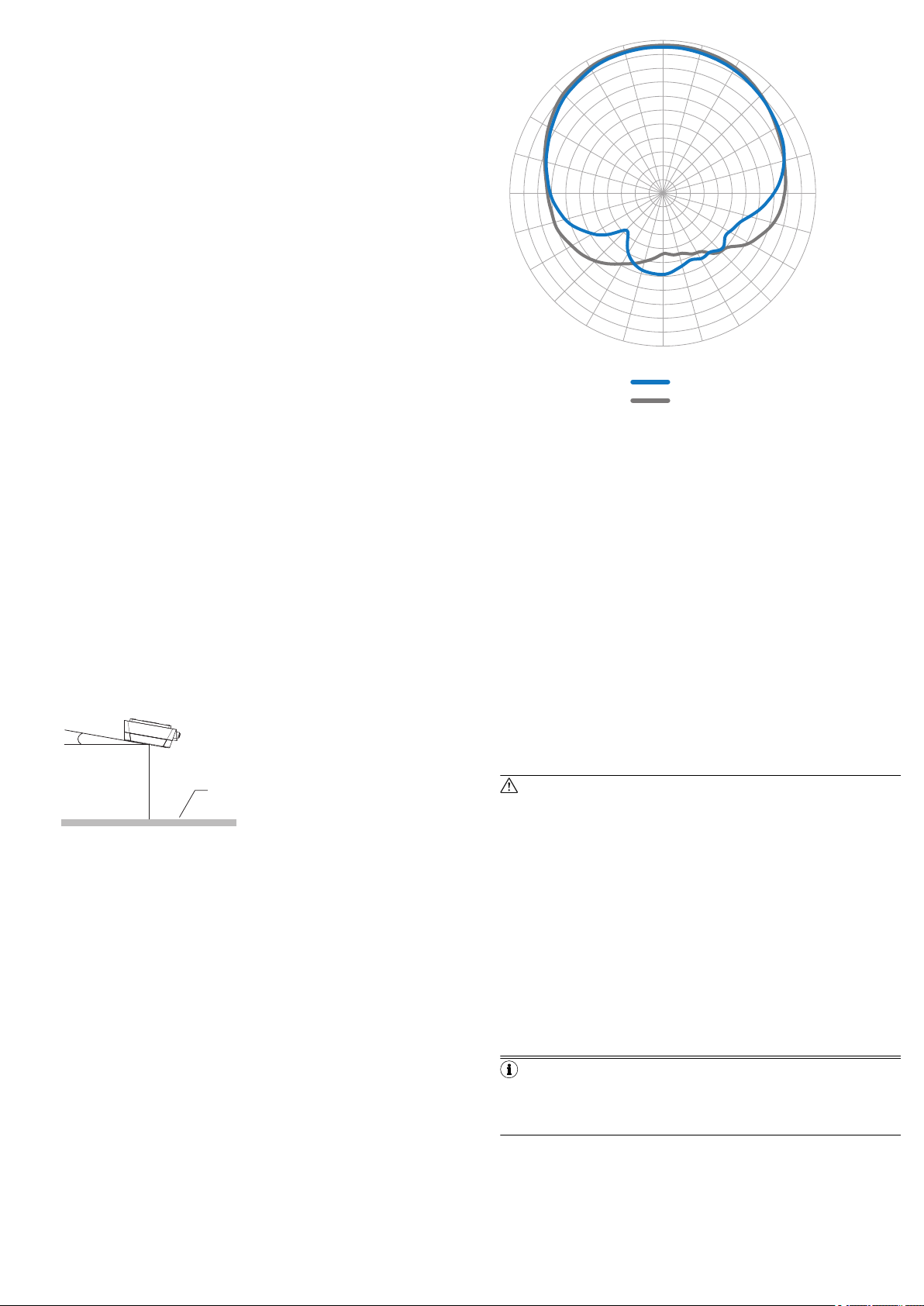
The radiation pattern shown here for the device’s antenna was obtained in a
reproducible environment (absorber chamber as a reflection-free space) for illus‐
trative purposes. The diagram shows how the UHF field propagates in the reflec‐
tion-free space, but cannot be used to draw any conclusions on the likely read
range in a real application on-site.
8023832/15YN/2019-12-11/en RFU61x | SICK 3
rately. Proceed as described under b).
transponder on the object. While doing so, take into account the shape,
alignment, and dimensions of the antenna field. Avoid as far as possible any
large metal surfaces positioned to the front. If this is not possible, do not
mount the antenna plane parallel with the surface.
Figure 2: Selection of the approach angle with a large metal surface on the
front. e.g., 10°
1
persons between the device and the transponder during the write or read
process. This will absorb or reflect the generated UHF field and thereby
reduce the read range.
Application-specific reflections can result in both overreaches and “holes”
Other factors that can significantly impact the read range include:
°
°
°
Metal surface
Quality of the transponder: antenna gain, the integrated transponder
chip and related sensitivity, reflected energy
Material of the carrier object (plastic, wood, metal)
Objects between the device and transponder that can affect the UHF
field (items, liquids, people)
Figure 3: Radiation pattern of the integrated antenna of the RFU61x (typical):
Measured antenna gain in dBic at 866.5 MHz, LHCP (left-hand circularly polar‐
ized)
1
2
Horizontal plane (azimuth)
Vertical plane (elevation)
5 Electrical installation
•
The electrical installation must only be performed by an electrically qualified person.
•
Standard safety requirements must be observed when working on electrical systems!
•
Electrical connections between the read/write device and other devices are
only allowed to be made or separated in a voltage-free state. Otherwise,
there is a risk of damaging the devices.
•
When using connecting or extension cables with an open end, make sure
that bare wire ends are not touching (risk of short-circuit when the supply
voltage is switched on). Wires must be appropriately insulated from each
other. This also applies to unused wires.
•
Wire cross-sections in the supply cable from the customer’s power system
must be designed in accordance with the applicable national standards.
•
Connect the device only to the permissible supply voltage, see Technical
data, page 6.
•
Protect the device with a separate fuse of 0.8 A (slow blowing) at the start of
the supply circuit.
•
All circuits connected to the device must be designed as ES1 circuits. The
voltage supply or power supply unit must satisfy ES1 requirements in accor‐
dance with the currently applicable EN 62368-1.
WARNING
Risk of injury and damage caused by electrical current!
As a result of equipotential bonding currents between the device and
other grounded devices in the system, faulty grounding of the device can
give rise to the following dangers and faults:
•
Dangerous voltages are applied to the metal housings.
•
Devices will behave incorrectly or be destroyed.
•
Cable shielding will be damaged by overheating and cause cable
fires.
Remedial measures
•
Only skilled electricians should be permitted to carry out work on
the electrical system.
•
If the cable insulation is damaged, disconnect the voltage supply
immediately and have the damage repaired.
•
Ensure that the ground potential is the same at all grounding
points.
•
Where local conditions do not meet the requirements for a safe
earthing method, take appropriate measures (e.g., ensuring lowimpedance and current-carrying equipotential bonding).
NOTE
For recommended measures for eliminating hazards, see the “Electrical
installation” chapter in the RFU61x RFID read/write device (UHF) operat‐
ing instructions on the product page on the Internet at www.sick.com/
RFU61x
Page 4

NOTICE
SOPAS ETSOPAS ET
PC
"Ethernet (Host 1/Aux 1)"
USBUSB
RFU61x-
106xx
Cable 3
5
"Power"
EthernetEthernet
"USB" (Aux 2), for temporary use only 4
Configuration
Reading result
display
Transponder
access
Reading
diagnostics
ReadyRFLink/Act
microSD
Cable 6
V
S
2
Trigger
sensor
1
Risk of damage to the device due to reverse polarit y of the supply voltage!
The supply voltage input for the device is designed with internal circuit
protection to provide reverse polarity protection. The internal functional
earth, which also corresponds to the negative pole of the supply voltage
for the device, is connected directly to the metal housing of the device
due to reasons relating to high frequency.
If the supply voltage is polarity-reversed, this will not cause any damage
provided that the following conditions are met for the device:
The device is not connected in an electrically conductive manner, either
via other cables or via its housing, to other peripheral devices which use
the same reference potential.
NOTE
For a more in-depth examination, see the “Electrical installation” chap‐
ter in the RFU61x RFID read/write device (UHF) operating instructions
on the product page on the Internet at www.sick.com/RFU61x.
5.1 Connecting the device electrically
NOTE
The USB interface of the device is used in industrial environments only as a
service interface for temporary use (e.g. for configuration, troubleshooting).
Permanent use in operational use of the system as a host interface is not
intended.
Voltage supply
There are two ways to supply the device with voltage, as follows:
1. Power and Ethernet: DC 18 V ... 30 V
°
Connection 1: power (DC 24 V)
°
Connection 2: Ethernet or PoE
2. Power over Ethernet (PoE): DC 48 V / 57 V according to PoE technology
°
Connection 1: not assigned
°
Connection 2: PoE
NOTE
The voltage supply via a power supply unit must be capable of bridging a
brief power failure of 20 ms.
Both variants can be combined. Recommendation: select only one variant.
Connecting connection variants at the same time
Initial situation Adjustment Effect
Voltage supply power via con‐
nection 1
Voltage supply PoE via con‐
nection 2
Voltage supply power via con‐
nection 1 (dominant) and PoE
via connection 2
Additionally, PoE connected
via connection 2.
Additionally, power con‐
nected via connection 1.
Connecting power via con‐
nection 1 is isolated.
No effect on the device sta‐
tus.
No effect on the device sta‐
tus.
Voltage supply with immedi‐
ate effect via power via con‐
nection 1 (dominant).
Device restarts.
Voltage supply with immedi‐
ate effect via PoE via connec‐
tion 2.
After successful initialization, the Ready LED illuminates green.
Trigger
Read and write commands for the device can be started and ended using a trig‐
ger sensor. A trigger sensor can be connected directly to the device (connection
3). The permanently active supply voltage is received by the trigger sensor from
the device. If connection 3 is not used, provide the female connector with a pro‐
tective plug. Additional information, see Technical data, page 6.
Connection 3: trigger
Figure 4: Female connector, M8, 4-pin, coded
Pin assignment of the “Trigger” connection
Pin Signal Function
1 VS
Trigger
Trigger supply voltage
2 NC NC
3 GND Functional ground
4 Sensor 1 Digital input
5.1.1 RFU610-106xx: Power and Ethernet
1
2
3
Trigger sensor for external read cycle (optional)
Supply voltage V
Adapter cable (male connector, USB, Micro-B type/male connector,
S
USB, type A)
4
USB, alternative to Ethernet Aux port. The USB interface is only for
temporary use as a service interface.
5
Configuration with SOPAS ET, prepared representation of the read
result, transponder access or reading diagnostics
6
Adapter cable (male connector, M12, 8-pin, X-coded/male connector,
RJ-45, 8-pin)
1. Connect connection 1 via a power adapter cable (e.g. part no. 2095607)
directly to a supply voltage.
2. Connect connection 2 via a Ethernet adapter cable (e.g. part no. 6049728)
directly to a PC.
3. Connect the trigger sensor (e.g. GL6 [part no. 1059241]) via a trigger
adapter cable (e.g. part no. 2096347) directly to connection 3 of the device.
Connection 1: power
Figure 5: Male connector, M12, 4-pin, A-coded
Pin assignment of the “Power” connection
Pin Signal Function
1 V
S
Supply voltage
2 NC NC
3 GND_ext Primary ground
4 NC NC
Connection 2: Ethernet
Figure 6: Female connector, M12, 8-pin, X-coded
Pin assignment of the “Ethernet” connection
Pin Signal Function
1 TD+ Sender+
2 TD– Sender–
3 RD+ Receiver+
4 RD– Receiver–
5 PoE– Supply voltage-
6 PoE– Supply voltage-
7 PoE+ Supply voltage+
8 PoE+ Supply voltage+
NOTE
The numbering of the data interfaces (Aux 1, etc.) in the following block dia‐
grams provides a better overview, but is not shown in configuration tools
such as the SOPAS ET configuration software.
8023832/15YN/2019-12-11/en RFU61x | SICK 4
Page 5

5.1.2 RFU610-106xx: Power over Ethernet (PoE)
SOPAS ETSOPAS ET
PC
"Ethernet (Aux 1)"
USBUSB
PoE Switch
(Endspan)
...
DC 48 V/57 V
PSE
**)
PD
*)
RFU61x-
106xx
*) PD = Powered Devices 6 **) PSE = Power Sourcing Equipment 5
"Ethernet"
Cable 2
4
EthernetEthernet
"USB" (Aux 2), for temporary use only 3
Configuration
Reading result
display
Transponder
access
Reading
diagnostics
PD
*)
EthernetEthernet
"Ethernet (Host 1/Aux 1)/Power"
Cable 7
ReadyRFLink/Act
microSD
Trigger
sensor
1
RFU610-106xx (PoE connection)
1
2
Trigger sensor for external read cycle (optional)
Adapter cable (male connector, USB, Micro-B type/male connector,
USB, type A)
3
USB, alternative to Ethernet Aux port. The USB interface is only for
temporary use as a service interface.
4
Configuration with SOPAS ET, prepared representation of the read
result, transponder access or reading diagnostics
5
6
7
PSE = Energy source
PD = Energy consumer
Adapter cable (male connector, M12, 8-pin, X-coded/male connector,
RJ-45, 8-pin)
1. Connect connection 2 via a PoE adapter cable (e.g. part no. 6049728)
directly with a PoE switch or PoE injector.
2. Connect the trigger sensor (e.g. GL6 [part no. 1059241]) via a trigger
adapter cable (e.g. 2096347) directly to connection 3 of the device.
Connection 2: PoE
Figure 7: Female connector, M12, 8-pin, X-coded
Pin assignment of the “PoE” connection
Pin Signal Function
1 TD+ Sender+
2 TD– Sender–
3 RD+ Receiver+
4 RD– Receiver–
5 PoE– Supply voltage-
6 PoE– Supply voltage-
7 PoE+ Supply voltage+
8 PoE+ Supply voltage+
Figure 8: SOPAS ET display of the detected transponders in the Quickstart window
Feedback about transponder detection in the UHF field
In Quickstart mode, the default lighting behavior of the process feedback LEDs
indicates whether a UHF field is present and whether the device has detected
transponders. The process feedback LEDs are located in the four corners of the
antenna cover and light up blue in this case. Choose between two brightness lev‐
els in SOPAS ET to adjust the brightness of the process feedback LEDs.
Process feedback LEDs
LED status Status
Lit up (permanently) No transponder in field
Flashing slowly (f = 1.25 Hz) 1 transponder in field
Flashing quickly (f = 2.5 Hz) 2 transponders in field
Flashing faster (f = 5 Hz) More than 2 transponders in field
NOTE
Quickstart mode is not intended to be used during normal operation. For
operational use, set a read cycle using the object trigger control in SOPAS ET.
6.3 Accessing the data on a transponder
1. In order to access the memory area of a transponder, click the Stop button in
Quickstart.
2. Highlight the desired transponder (click it with the mouse).
3. Click the Transponder Access button. The Transponder Management Access tab dis‐
plays the content of the selected transponder.
6 Commissioning and configuration with computer (Windows
PC)
Adaptation of the device parameters to the application as well as diagnostics in
the event of malfunctions take place as default with the SOPAS ET configuration
software.
6.1 Installing and starting the configuration software
1. Download and install the latest version of the SOPAS ET configuration soft‐
ware, as well as the current device description files (*.sdd):
www.sick.com/SOPAS_ET. In this case, select the “Complete” option as sug‐
gested by the installation wizard. Administrator rights may be required on the
computer (PC) to install the software.
2. Start the “SOPAS ET” program option after completing the installation. Path:
Start > Programs > SICK > SOPAS ET Engineering Tool > SOPAS.
3. Establish communication between SOPAS ET and device with the automati‐
cally launching wizard. To do so, select the RFU610-106xx under the devices
available depending on the connected communication interface, e.g. in the
Ethernet (default Ethernet address: IP address: 192.168.0.1, subnet mask:
255.255.255.0). SOPAS ET establishes communication with the device and
loads the associated device description file. The Quickstart tab opens.
6.2 Detecting a transponder in Quickstart mode
1. Bring one or more standards-compliant UHF transponders into the working
2. Click the Start button on the Quickstart tab of SOPAS ET. SOPAS ET generates
range of the integrated antenna of the device. The UII/EPC of the individual
transponders must be differentiated so that the device can detect several
transponders.
an automated read cycle and lists the detected transponders one after
another in the Quickstart window.
8023832/15YN/2019-12-11/en RFU61x | SICK 5
Figure 9: SOPAS ET: Transponder Access display window
Page 6

NOTE
The device cannot write the TID (tag identifier) of the transponder.
6.4 Continuing the configuration
1. Under SOPAS ET in the left-hand navigation tree, edit the required tabs for
the application using the additional entries under Parameters.
These include amongst others:
°
antenna configuration, performance optimization, data pre-processing,
transponder processing
°
Object trigger control (e.g. via digital input “Sensor 1”), data processing
and output
°
Data output interface(s), function of the digital input and use of an
optional memory card if necessary.
2. Set the transmitting power for the integrated antenna using sliders on the
Antenna Configuration tab.
°
Regional permissible values for the antenna, see Device overview,
page 7.
°
Transmitting power default RFU610-106xx: 10 dBm (10 mW)
Figure 10: SOPAS ET: Example setting for the integrated antenna
3. Test and, if necessary, modify the settings made during operational use of
the system.
6.5 Completing the configuration
Permanently save the entire configuration once it has been successfully
b
tested:
°
Parameter set in the device: Click the button
°
Configuration file on the PC: Click buttons Device > Export SDV file.
.
7 Maintenance and care
The device does not contain components that require maintenance.
If it is contaminated (e.g. metal dust), clean the front of the device (antenna
hood) carefully using a soft, damp cloth (with a mild cleaning agent) in order
to achieve the full read and write speed. The antenna hood is made of plas‐
tic.
8 Transport and storage
Transport and store the device in the original packaging, with protective plugs and
caps completely screwed-on. Do not store outdoors. To ensure that any residual
moisture present can escape, do not store the device in airtight containers. Do
not expose to any aggressive substances.
Storage conditions: dry, dust-free, no direct or indirect sunlight, as little vibration
as possible. Storage temperature and relative humidity see Technical data,
page 6.
9 Repairs
Repair work on the device may only be performed by qualified and authorized ser‐
vice personnel from SICK AG.
10 Disassembly and disposal
Any device which can no longer be used must be disposed of in an environmen‐
tally friendly manner in accordance with the applicable national waste disposal
regulations. As it is categorized as electronic waste, the device must never be dis‐
posed of with household waste!
11 Technical data
11.1 Features
RFU610-106xx
Version
(working range)
Product category RFID read/write device (UHF) with integrated antenna
Frequency band UHF (860 MHz ... 960 MHz)
Radio equipment
approval
(regional assignment)
Carrier frequency
Transmitting power
RFID standard (air inter‐
face)
Modulation PR-ASK
Connection type Power and Ethernet or PoE
Short range
Depending on type, see Device overview, page 7
EPCglobal UHF Class 1 Generation 2, ISO/IEC 18000-6 C
RFU610-106xx
Read range Typically: 0.5 m
Antenna
Service functions Semi-automated saving of parameter data (parameter cloning)
Integrated antenna
•
Transmitting power: adjustable
•
Polarization: circular (LHCP 2))
•
Axis behavior: typically 2 dB (ETSI), 3 dB (FCC)
•
Aperture angle: 110°
•
Front-to-back ratio: typically > 5 dB
outside the device memory:
•
Using insertable microSD memor y card 3) in the device
1)
Clock Network time protocol (NTP), no internal clock
Conformities Depending on type. See type-specific online data sheet at:
Certificates Depending on type. See “Downloads” section online at:
1)
The read range depends on the transponder used and the ambient conditions.
2)
LHCP = left-hand circular polarization.
3)
Optional accessories.
4)
UL-certified if the type label contains the UL logo and the UL conditions are met during
device operation.
www.sick.com/RFU61x
UL: RFU610-10601 (USA and Canada)
www.sick.com/RFU61x
4)
11.2 Interfaces
RFU610-106xx
Ethernet
PROFINET
EtherNet/IP™
3)
USB 2.0
Digital input
•
Protocol: TCP/IP
•
Function: host (data output of the read result)
•
Function: Aux (service)
•
Data transmission rate 10/100 Mbit/s
•
Services: DHCP, NTP, HTTP/HTTPS
•
Protocol: PROFINET
•
Function: host (data output of read result), PROFINET Single
2)
Port
•
Data transmission rate 10/100 Mbit/s
•
Protocol: EtherNet/IP™
•
Function: host (data output of the read result)
•
Data transmission rate 10/100 Mbit/s
•
Function: Aux (service)
•
Version: physical, switching
4)
•
V
= max. 30 V, Iin 5) = max. 5 mA. V
in
max. 40 mA
•
Debounce time: adjustable
•
A corresponding trigger sensor (e.g. GL 6) can be connected
1)
1)
6) = VS, I
S Trigger
8)
S trigger
directly
Optical indicators
•
4 RGB LEDs (status indicators) on front top
•
4 x RGB LEDs (process feedback) in the four corners of the
antenna cover. Display function can be set with pre-defined
color assignment 8).
Configuration SOPAS ET configuration software, CoLa commands (telegrams),
Programming Application-specific programming with SICK AppStudio 9) devel‐
1)
Service: e.g. configuration, diagnosis, transponder access or prepared representation of
the read result.
2)
Function blocks for PLC types from different manufacturers are available online at:
www.sick.com/RFU61x.
3)
USB interface only for temporary use (servicing).
4)
Input voltage.
5)
Input current.
6)
Supply voltage for external trigger sensor.
7)
Supply current for external trigger sensor.
8)
For example using the SOPAS ET configuration software.
9)
This functionality can be unlocked with the SDK6U SD card. Available online at:
www.sick.com
web server, fieldbus controller (PLC) with additional suppor t by
SICK function blocks
opment environment.
You can find further information on the Internet at:
www.sick.com/SICK_AppStudio
11.3 Mechanics and electronics
RFU610-106xx
Electrical connection
Supply voltage V
S
•
Connection 1: male connector, M12, 4-pin, A-coded
•
Connection 2: female connector, M12, 8-pin, X-coded
•
Connection 3: female connector, M8, 4-pin, coded
•
USB interface: female connector, 5-pin, Micro B type
ES1 according to EN 62368-1, NEC protection class 2
(UL13010)
•
Power and Ethernet: DC 18 V ... 30 V
•
PoE: DC 48 V / 57 V according to PoE technology
7) =
8023832/15YN/2019-12-11/en RFU61x | SICK 6
Page 7

RFU610-106xx
Power consumption
•
Operation: 6 W typical
•
Standby: 3 W typical
1)
Housing Cast aluminum, plastic (PPS)
Housing color Black, silver
Side cover Plastic foil, can be opened for temporary access to USB interface
MTBF 22 years
and memory card slot
2)
Enclosure rating IP67 (EN 60529:1991-10/A2:2000-02)
Protection class III (EN 61140:2006-08)
Safety EN 62368-1:2014
Weight Approx. 313 g
Dimensions (L x W x H) 92 mm x 80 mm x 38 mm
1)
At full transmitting power.
2)
Continuous operation at an ambient operating temperature of +50 °C.
3)
With any protruding connection or fastening elements, see Device view, page 2.
3)
11.4 Ambient data
RFU610-106xx
Electromagnetic compati‐
bility (EMC)
Vibration resistance IEC 60068-2-6:2007 (10 Hz ... 150 Hz / 5 g sine)
Shock resistance IEC 60068-2-27:2008 (30 g / 6 ms / 12 shocks per axis/half
Ambient temperature
Permissible relative
humidity
1)
Storage conditions see Transport and storage, page 6.
EN 301489-1 V2.1.1 (2017)
EN 301489-3 V1.6.1 (2013)
IEC 60068-2-64: 2008 (10 Hz ... 500 Hz / 3.5 g RMS)
sine and 25 g / 6 ms / 200 shocks per axis/half sine)
•
Operation: -25 °C ... +50 °C
•
Storage 1): -40 °C ... +70 °C
0% ... 90%, non-condensing
12 Device overview
RFU610-106xx: Device overview
Regional
assign‐
ment
Europe/
South
Africa
USA/
Canada/
Mexico
India V2.07 865.7 MHz …
China V2.07 902.625 MHz
Japan V2.07 916.8 MHz ...
1)
2)
12.1 Operational restrictions
France
The RFU610-106xx must not be operated within a 20 km radius of 13 military
zones.
Lithuania
Firmwa
Carrier fre‐
re from
quency
version
V2.06 865.7 MHz ...
867.5 MHz
V2.06 902.75 MHz ...
927.25 MHz
866.9 MHz
...
924.375 MHz
920.4 MHz
ERP = equivalent radiated power.
EIRP = equivalent isotropic radiated power.
Transmitting
power of the
integrated
antenna
Max. 25 mW
(ERP 1))
Max. 40 mW
(EIRP 2))
Max. 25 mW
(ERP 1))
Max. 25 mW
(ERP 1))
Max. 40 mW
(EIRP 2))
Device
type
RFU61010600
RFU61010601
RFU61010603
RFU61010605
RFU61010607
Part no. Supplied
1091102 English
1099890 English
1104443 English
1101394 English
1104447 English
Quickstarts
(part no.)
(8023832),
German
(8024099)
(8023832),
French
(8024100),
Spanish
(8024101)
(8023832)
(8023832),
Chinese
(8024104)
(8023832),
Japanese
(8024103)
NOTICE
Operational restric tions!
Depending on its type, the RFU610-106xx is configured in its frequency band
so that it corresponds to the respective region-dependent specifications. The
relevant settings cannot be changed.
Without interfering with nationally protected frequencies (e.g. mobile radio),
the device can be operated in the following assigned regions depending on
the type, see Device overview, page 7"Device type" and "Regional assign‐
ment" column.
Operating the same RFU610-106xx in other regions can interfere with pro‐
tected frequencies.
•
Only use the RFU610-106xx in the region for which a certification is
available.
•
When reselling the RFU610-106xx, inform the buyer that the regional
assignment cannot be changed.
USA
(1) This device complies with part 15 of the FCC Rules. Operation is subject to the
following two conditions:
(1) This device may not cause harmful interference, and (2) this device must
accept any interference received, including interference that may cause undesired
operation.
(2) Changes or modifications not expressly approved by the party responsible for
compliance could void the user’s authority to operate the equipment.
(3) Note: This equipment has been tested and found to comply with the limits for
a Class A digital device, pursuant to part 15 of the FCC Rules. These limits are
designed to provide reasonable protection against harmful interference when the
equipment is operated in a commercial environment. This equipment generates,
uses, and can radiate radio frequency energy and, if not installed and used in
accordance with the instruction manual, may cause harmful interference to radio
communications. Operation of this equipment in a residential area is likely to
cause harmful interference in which case the user will be required to correct the
interference at his own expense.
(4) To comply with FCC part 15 rules in the United States, the system must be pro‐
fessionally installed to ensure compliance with the Part 15 certification.
(5) It is the responsibility of the operator and profes-sional installer to ensure that
only certified systems are deployed in the United States. The use of the system in
any other combination (such as co-located antennas transmitting the same infor‐
mation) is expressly forbidden.
(6) This device complies with the limit values defined by the FCC for radio radia‐
tion in an uncontrolled environment. The device must have a minimum distance
of 20 cm between the source of radiation and your body.
Canada
(1) This Class A digital apparatus complies with Canadian ICES-003.
(2) This device satisfies the Industry Canada CNR applicable to license-free radio
equipment. Use is permitted providing the two following conditions are met: (1)
The device must not cause any faults and (2) the user of the device must accept
any fault produced in the device, even if this may impair its function.
Korea
Class A Equipment (Industrial Use)
This device (Class A, EMC) is designed for industrial environments. As the seller
and user, please observe this requirement and do not use in household applica‐
tions!
Taiwan
Warning: For already-certified radio frequency devices with low power, the fre‐
quencies must not be changed, the power increased nor the properties and func‐
tions of the original design changed by companies or users without permission.
The use of radio frequency devices with low power must not impair flight safety
nor disturb legal communication; if faults are identified, use must be terminated
immediately and improvements must be made until no more faults are present
before further use is permissible. Legal communication from the previous point
refers to radio communication carried out in accordance with the regulations of
the Telecommunications Act. Radio frequency devices with low power must toler‐
ate faults caused by legal communication and industrial, scientific and medical
devices and systems which emit radio waves.
13 Sources for obtaining more information
Additional information about the device, its optional accessories, and fieldbus
modules can be found in electronic format on the following product pages on the
Internet at:
13.1 RFID read/write device RFU610 (UHF)
www.sick.com/RFU61x
Ordering information
•
Device and its regional radio variants
•
Compatible accessories, including transponders, cables, brackets, trigger
sensors
Documentation
•
Online data sheet: summary of type-specific technical data including dimen‐
sional drawing for the selected device
•
Quickstart RFID read/write device RFU610 (UHF)
•
RFID read/write device operating instructions RFU61x (UHF)
•
Technical information RFU parameters to support the configuration of the
device
•
Dimensional drawing and 3D CAD dimension models of the device in various
electronic formats
•
On request: Overview of the command strings of the device
•
Documentation of accessories (mounting systems)
Certificates
•
EU declaration of conformity and further certificates
Software
•
SOPAS ET configuration software
•
SDD files (device description files for SOPAS ET)
•
Function blocks for communication between a programmable logic controller
(PLC) from different manufacturers and the device or the fieldbus modules.
Support is also available from your sales partner: www.sick.com
13.2 Copyright notices
Open source programs
SICK uses open-source software in the device. This software is licensed by the
rights holders using the following licenses among others: the free licenses GNU
General Public License (GPL Version2, GPL Version3) and GNU Lesser General
There may be restrictions in Lithuania (extent not currently known).
8023832/15YN/2019-12-11/en RFU61x | SICK 7
Page 8

Public License (LGPL), the MIT license, zLib license, and the licenses derived from
the BSD license.
This program is provided for general use, but WITHOUT ANY WARRANTY OF ANY
KIND. This warranty disclaimer also extends to the implicit assurance of mar‐
ketability or suitability of the program for a particular purpose.
More details can be found in the GNU General Public License.
View the complete license texts here: www.sick.com/licensetexts
Printed copies of the license texts are also available on request.
8023832/15YN/2019-12-11/en RFU61x | SICK 8
 Loading...