

SICK RFU610-10600,RFU61 Series,RFU610-10601 Operating Instructions Manual

RFU61x
RFID read/write device (UHF)
O P E R A T I N G I N S T R U C T I O N S

Described product
RFU610-106xx
Manufacturer
SICK AG
Erwin-Sick-Str. 1
79183 Waldkirch
Germany
Legal information
This work is protected by copyright. Any rights derived from the copyright shall be
reserved for SICK AG. Reproduction of this document or parts of this document is only
permissible within the limits of the legal determination of Copyright Law. Any modifica‐
tion, abridgment or translation of this document is prohibited without the express writ‐
ten permission of SICK AG.
The trademarks stated in this document are the property of their respective owner.
© SICK AG. All rights reserved.
Original document
This document is an original document of SICK AG.
Conformities
Due to the country-specific approvals for the device, the respective conformance infor‐
mation is type-dependent. For the specific device that you have, see the online typespecific data sheet at:
www.sick.com/RFU61x
•
The type designation of your device can be found on the type label.
The trademarks mentioned in this document are the property of the respective owners.
2
O PE R AT I NG IN S TR U CT I ON S | RFU61x 8024536//2019-08-30 | SICK
Subject to change without notice

Contents
CONTENTS
1 About this document........................................................................ 5
1.1 Information on the operating instructions.............................................. 5
1.2 Scope......................................................................................................... 5
1.3 Explanation of symbols............................................................................ 6
1.4 Further information................................................................................... 7
1.5 SICK service.............................................................................................. 7
2 Safety information............................................................................ 8
2.1 Intended use............................................................................................. 8
2.2 Improper use............................................................................................. 9
2.3 Internet protocol (IP) technology.............................................................. 9
2.4 Limitation of liability................................................................................. 9
2.5 Modifications and conversions................................................................ 10
2.6 Requirements for skilled persons and operating personnel.................. 11
2.7 Operational safety and particular hazards.............................................. 12
2.8 Repairs...................................................................................................... 12
3 Product description........................................................................... 13
3.1 Product ID.................................................................................................. 13
3.2 Product characteristics............................................................................ 15
4 Transport and storage....................................................................... 22
4.1 Transport................................................................................................... 22
4.2 Unpacking.................................................................................................. 22
4.3 Transport inspection................................................................................. 22
4.4 Storage...................................................................................................... 22
5 Mounting............................................................................................. 24
5.1 Overview of mounting procedure............................................................. 24
5.2 Preparation for mounting......................................................................... 24
5.3 Mounting location..................................................................................... 26
5.4 Mounting the device................................................................................. 27
5.5 Mounting external components............................................................... 28
6 Electrical installation........................................................................ 30
6.1 Safety......................................................................................................... 30
6.2 Wiring instructions.................................................................................... 34
6.3 Overview of all interfaces and connection options................................ 35
6.4 Pin assignments of electrical connections............................................. 39
6.5 Instructions for electrical installation when the ambient temperature
can fall below 0 °C................................................................................... 40
6.6 Installation steps...................................................................................... 41
6.7 Connecting the supply voltage................................................................. 43
6.8 Wiring the digital input............................................................................. 45
6.9 Wiring the data interface.......................................................................... 46
8024536//2019-08-30 | SICK O PE R AT I NG IN S TR U CT I ON S | RFU61x
Subject to change without notice
3

CONTENTS
7 Commissioning.................................................................................. 47
7.1 Overview of the Commissioning Steps.................................................... 47
7.2 SOPAS ET configuration software............................................................ 47
7.3 Starting the SOPAS ET configuration software and connecting it to
the device.................................................................................................. 48
7.4 Initial commissioning................................................................................ 49
8 Operation............................................................................................ 51
8.1 Operating and status indicators.............................................................. 51
9 Maintenance...................................................................................... 55
9.1 Maintenance plan..................................................................................... 55
9.2 Cleaning..................................................................................................... 55
10 Troubleshooting................................................................................. 56
10.1 Overview of Potential Errors and Faults.................................................. 56
10.2 Detailed fault analysis.............................................................................. 56
10.3 Status log.................................................................................................. 57
10.4 SICK service.............................................................................................. 57
10.5 Repairs...................................................................................................... 57
10.6 Returns...................................................................................................... 57
10.7 Replacing the device................................................................................ 58
11 Decommissioning............................................................................. 60
11.1 Disposal..................................................................................................... 60
12 Technical data.................................................................................... 61
12.1 Features.................................................................................................... 61
12.2 Interfaces.................................................................................................. 62
12.3 Mechanics and electronics...................................................................... 62
12.4 Ambient data............................................................................................. 63
12.5 Working range diagram............................................................................ 63
12.6 Dimensional drawing................................................................................ 63
13 Accessories........................................................................................ 64
14 Annex.................................................................................................. 65
14.1 EU declaration of conformity / Certificates............................................. 65
14.2 Certification according to UL61010-1..................................................... 65
14.3 Signal assignment of cables with open cable end at one end.............. 65
14.4 Copyright notices...................................................................................... 66
14.5 Abbreviations used................................................................................... 66
4
O PE R AT I NG IN S TR U CT I ON S | RFU61x 8024536//2019-08-30 | SICK
Subject to change without notice

1 About this document
1.1 Information on the operating instructions
These operating instructions provide important information on how to use devices from
SICK AG.
Prerequisites for safe work are:
Compliance with all safety notes and handling instructions supplied.
•
Compliance with local work safety regulations and general safety regulations for
•
device applications
The operating instructions are intended to be used by qualified personnel and electrical
specialists.
NOTE
Read these operating instructions carefully to familiarize yourself with the device and its
functions before commencing any work.
The operating instructions are an integral part of the product. Store the instructions in
the immediate vicinity of the device so they remain accessible to staff at all times.
Should the device be passed on to a third party, these operating instructions should be
handed over with it.
ABOUT THIS DOCUMENT
1
1.2 Scope
These operating instructions do not provide information on operating the machine or
system in which the device is integrated. For information about this, refer to the operat‐
ing instructions of the specific machine.
These operating instructions serve to incorporate the device into a customer system.
These operating instructions form part of the documentation provided to users. The
operating instructions supplement the Quick Start Guide with more detailed and addi‐
tional information. The Quick Start guide for initial commissioning is enclosed with the
devices in printed form. The Quick Start guide can also be downloaded from the follow‐
ing website:
www.sick.com/RFU61x
•
The operating instructions provide in-depth information on the following topics:
Interpreting the type code
•
Overview of product features and functions of the device
•
Scope of delivery of the device: enclosed components, required online access to
•
additional components
Operation of the device in an ambient temperature range below 0 °C: measures
•
and requirements for mounting and electrical installation
Applications with spatially distributed systems: measures to prevent possible
•
ground potential equalizing currents
Overview of all interfaces and connection options for the device
•
Wiring the individual interfaces of the device
•
Additional functions of the status indicators
•
Overview of operating options and available configuration tools for the device
•
Measures for eliminating interference
•
Step-by-step procedures are given for all required actions in the operating instructions.
These instructions apply to all available device variants of the product. Functions spe‐
cific to special devices are, where necessary, described in additional documents.
8024536//2019-08-30 | SICK O PE R AT I NG IN S TR U CT I ON S | RFU61x
Subject to change without notice
5
1 ABOUT THIS DOCUMENT
More detailed information for identification of the available device type see "Type code",
page 13.
The available device variants, and information about the regionally related radio equip‐
ment approvals are listed on the online product page:
•
Commissioning is described in the operating instructions using one particular device
variant as an example. Commissioning is based on the basic parameter setting of the
device. Reading a transponder on an object serves as the basis for the simple applica‐
tion.
NOTE
The device approval was granted for a specific region. The region assignment cannot be
changed.
•
•
•
•
www.sick.com/RFU61x
Only use the device in the region for which it has been approved.
When reselling the device, inform the buyer of the fixed region assignment.
Should the device be passed on to a third party, these operating instructions and
the Quick Start Guide should be handed over with it.
For country-specific special features in the operation of the device, see “Operating
restrictions” in the Quick Start Guide. A printed copy of the Quick Start Guide is
supplied with the device. The Quick Start Guide can also be accessed in PDF for‐
mat on the device product page on the Internet at: www.sick.com/RFU61x.
1.3 Explanation of symbols
Warnings and important information in this document are labeled with symbols. Signal
words introduce the instructions and indicate the extent of the hazard. To avoid acci‐
dents, damage, and personal injury, always comply with the instructions and act care‐
fully.
DANGER
… indicates a situation of imminent danger, which will lead to a fatality or serious
injuries if not prevented.
WARNING
… indicates a potentially dangerous situation, which may lead to a fatality or serious
injuries if not prevented.
CAUTION
… indicates a potentially dangerous situation, which may lead to minor/slight injuries if
not prevented.
NOTICE
… indicates a potentially harmful situation, which may lead to material damage if not
prevented.
NOTE
… highlights useful tips and recommendations as well as information for efficient and
trouble-free operation.
6
O PE R AT I NG IN S TR U CT I ON S | RFU61x 8024536//2019-08-30 | SICK
Subject to change without notice

1.4 Further information
NOTE
Further documentation for the device can be found on the online product page at:
www.sick.com/RFU61x
•
There, additional information has been provided depending on the product, such as:
Model-specific online data sheets for device variants, containing technical data,
•
dimensional drawing, and specification diagrams
EU declarations of conformity for the product family
•
Certificates of the product family
•
Dimensional drawings and 3D CAD dimension models of the device variants in var‐
•
ious electronic formats
Quick Start guides for initial commissioning of the device
•
This documentation, available in English and German, and in other languages if
•
necessary
Other publications related to the devices described here
•
Publications dealing with accessories
•
NOTE
In addition to the existing operating instructions, the use of the RFU parameter descrip‐
tion is recommended. This document explains the UHF-RFID-specific parameters of all
device variants of the RFU6xx product family at the "Service” user level.
The parameter description supports the user in configuring applications with the
SOPAS ET configuration software.
ABOUT THIS DOCUMENT 1
1.5 SICK service
If you require any technical information, our SICK Service will be happy to help. To find
your agency, see the final page of this document.
NOTE
Before calling, make a note of all type label data such as type code, serial number, etc.,
to ensure faster processing.
8024536//2019-08-30 | SICK O PE R AT I NG IN S TR U CT I ON S | RFU61x
Subject to change without notice
7
2 SAFETY INFORMATION
2 Safety information
2.1 Intended use
The RFU61x RFID read/write device is an intelligent ID sensor from the SICK RFU6xx
(UHF) product family. Version (working range): Short Range.
The device is used for the automated, fixed identification of wireless-based data cards
(transponders) on moving or stationary objects, and for the management of these data
cards. The RFU610 base model processes all standard passive transponders in accor‐
dance with EPCglobal UHF C1G2 and ISO/IEC 18000-6C in the regional UHF carrier fre‐
quency range.
The device works in stand-alone operation. In read mode, the device transmits the
results via a host interface to a higher-level computer (e.g. PLC) for further centralized
processing. Network operation is possible for coordinating trouble-free readings of
devices at close proximity to one another, but without a coordinating summary of the
reading results by one of the devices involved.
The compact device contains an antenna integrated in the housing.
The device allows operation within a wide ambient temperature range. For details, see
"Technical data", page 61.
The device is primarily designed for use in industrial and logistics areas, and meets the
requirements for industrial ruggedness, interfaces and data processing. If necessary,
the device can be programmed to implement customer-specific modifications.
NOTE
The USB interface of the device is used in industrial environments only as a service
interface for temporary use (e.g. for configuration, troubleshooting). Permanent use in
operational use of the system as a host interface is not intended.
SICK AG assumes no liability for losses or damage arising from the use of the product,
either directly or indirectly. This applies in particular to use of the product that does not
conform to its intended purpose and is not described in this documentation.
2.1.1 Operational restrictions
NOTICE
Operational restrictions!
The frequency band of the device is configured for the specific type and region when
delivered. This enables the device to be operated in the respective approved region
without interfering with protected frequencies (such as mobile communications).
Operating the device in other regions, however, can interfere with protected frequen‐
cies.
■
Only use the device in the region for which it has been approved.
■
When reselling the device, inform the buyer of the fixed region assignment.
■
Should the device be passed on to a third party, these operating instructions and
the Quick Start Guide should be handed over with it.
■
For further country-specific operating requirements, see the Quick Start Guide, a
printed copy of which is enclosed with the device or can be downloaded online
(PDF) at:
°
www.sick.com/RFU61x
A region consists either of a group of countries or of only one country.
8
O PE R AT I NG IN S TR U CT I ON S | RFU61x 8024536//2019-08-30 | SICK
Subject to change without notice
2.1.2 Regulatory notes
Europe: simplified EU declaration of conformity
SICK AG hereby declares that the RFU61x-106xx radio equipment complies with the
2014/53/EU directive. The complete text of the EU declaration of conformity is avail‐
able at the following web address:
•
2.2 Improper use
Any use outside of the stated areas, in particular use outside of the technical specifica‐
tions and the requirements for intended use, will be deemed to be incorrect use.
•
•
•
WARNING
Danger due to improper use!
Any improper use can result in dangerous situations.
Therefore, observe the following information:
■
■
SAFETY INFORMATION 2
www.sick.com/RFU61x
The device does not constitute a safety component in accordance with the respec‐
tive applicable safety standards for machines.
The device must not be used in explosion-hazardous areas, in corrosive environ‐
ments or under extreme environmental conditions.
Any use of accessories not specifically approved by SICK AG is at your own risk.
Device should be used only in accordance with its intended use.
All information in these operating instructions must be strictly observed.
2.3 Internet protocol (IP) technology
NOTE
SICK uses standard IP technology in its products. The emphasis is placed on availability
of products and services.
SICK always assumes the following prerequisites:
The customer ensures the integrity and confidentiality of the data and rights
•
affected by its own use of the aforementioned products.
In all cases, the customer implements the appropriate security measures, such as
•
network separation, firewalls, virus protection, and patch management.
2.4 Limitation of liability
Relevant standards and regulations, the latest technological developments, and our
many years of knowledge and experience have all been taken into account when com‐
piling the data and information contained in these operating instructions. The manufac‐
turer accepts no liability for damage caused by:
■
Failing to observe the operating instructions
■
Incorrect use
■
Use of untrained staff
■
Unauthorized conversions
■
Technical modifications
■
Use of unauthorized spare parts, consumables, and accessories
With special variants, where optional extras have been ordered, or owing to the latest
technical changes, the actual scope of delivery may vary from the features and illustra‐
tions shown here.
8024536//2019-08-30 | SICK O PE R AT I NG IN S TR U CT I ON S | RFU61x
Subject to change without notice
9
2 SAFETY INFORMATION
NOTE
The product is a programmable device. The respective programmer is therefore respon‐
sible for his/her programming work and the resultant operation of the device. The liabil‐
ity and warranty of SICK AG is limited to the device specification (hardware functionality
and any programming interfaces) according to the agreed conditions. SICK AG will
therefore not be liable, among other things, for any damages resulting from the pro‐
gramming of the product by the customer or third parties.
2.5 Modifications and conversions
NOTICE
Modifications and conversions to the device may result in unforeseeable dangers.
Interrupting or modifying the device or SICK software will invalidate any warranty claims
against SICK AG. This applies in particular to opening the housing, even as part of
mounting and electrical installation.
2.5.1 Exception: temporarily opening the cover on the device
NOTICE
The user may open the housing only in order to obtain temporary access to the USB
interface or the slot for the optional memory card. For this purpose, the corresponding
side cover on the device can be opened temporarily.
In open state, the device does not conform to a specified enclosure rating. The device
must be protected appropriately against moisture and dust.
Operate the device only for a short time without closed cover.
b
NOTE
The USB interface of the device is used in industrial environments only as a service
interface for temporary use (e.g. for configuration, troubleshooting). Permanent use in
operational use of the system as a host interface is not intended.
For further warranty provisions, see the General Terms and Conditions of SICK AG, e.g.
on the delivery note of the device.
2.5.2 Conditions for specified enclosure rating
To ensure compliance with the specified IP67 enclosure rating of the device, the follow‐
ing requirements must be met. If these requirements are not met, the device does not
fulfill any specified enclosure rating.
The joint side cover for the USB interface and the memory card slot is placed
•
against the device and screwed on tight.
The cables plugged into the electrical M12 and M8 connections must be screwed
•
tight.
Any M12 and M8 connections that are not being used must be sealed with protec‐
•
tive plugs or caps, depending on type. These plugs or caps must be screwed tight
(as in the delivery condition).
The same also applies to the EMC requirement (ESD) according to CE.
10
NOTICE
The type label on the lower side of the device contains a pressure equalizing membrane
attached in the middle. If the type label is damaged or removed, the leak tightness of
the device can no longer be guaranteed.
O PE R AT I NG IN S TR U CT I ON S | RFU61x 8024536//2019-08-30 | SICK
Subject to change without notice
Positions of the individual elements see "Device view", page 15
NOTICE
The device can, if necessary, be operated for a short time without the side cover to per‐
form the following tasks:
Inserting or removing the optional memory card
•
Temporary use of the USB interface as a servicing interface
•
During this time, protect the device against moisture and dust.
2.6 Requirements for skilled persons and operating personnel
WARNING
Risk of injury due to insufficient training.
Improper handling of the device may result in considerable personal injury and material
damage.
■
All work must only ever be carried out by the stipulated persons.
This product documentation refers to the following qualification requirements for the
various activities associated with the device:
■
Instructed personnel have been briefed by the operator about the tasks assigned
to them and about potential dangers arising from improper action.
■
Skilled personnel have the specialist training, skills, and experience, as well as
knowledge of the relevant regulations, to be able to perform tasks delegated to
them and to detect and avoid any potential dangers independently.
■
Electricians have the specialist training, skills, and experience, as well as knowl‐
edge of the relevant standards and provisions to be able to carry out work on elec‐
trical systems and to detect and avoid any potential dangers independently. In Ger‐
many, electricians must meet the specifications of the BGV A3 Work Safety Regu‐
lations (e.g. Master Electrician). Other relevant regulations applicable in other
countries must be observed.
SAFETY INFORMATION 2
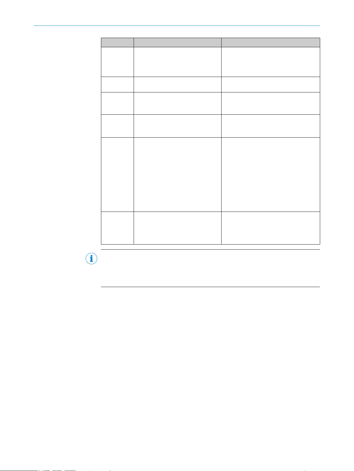
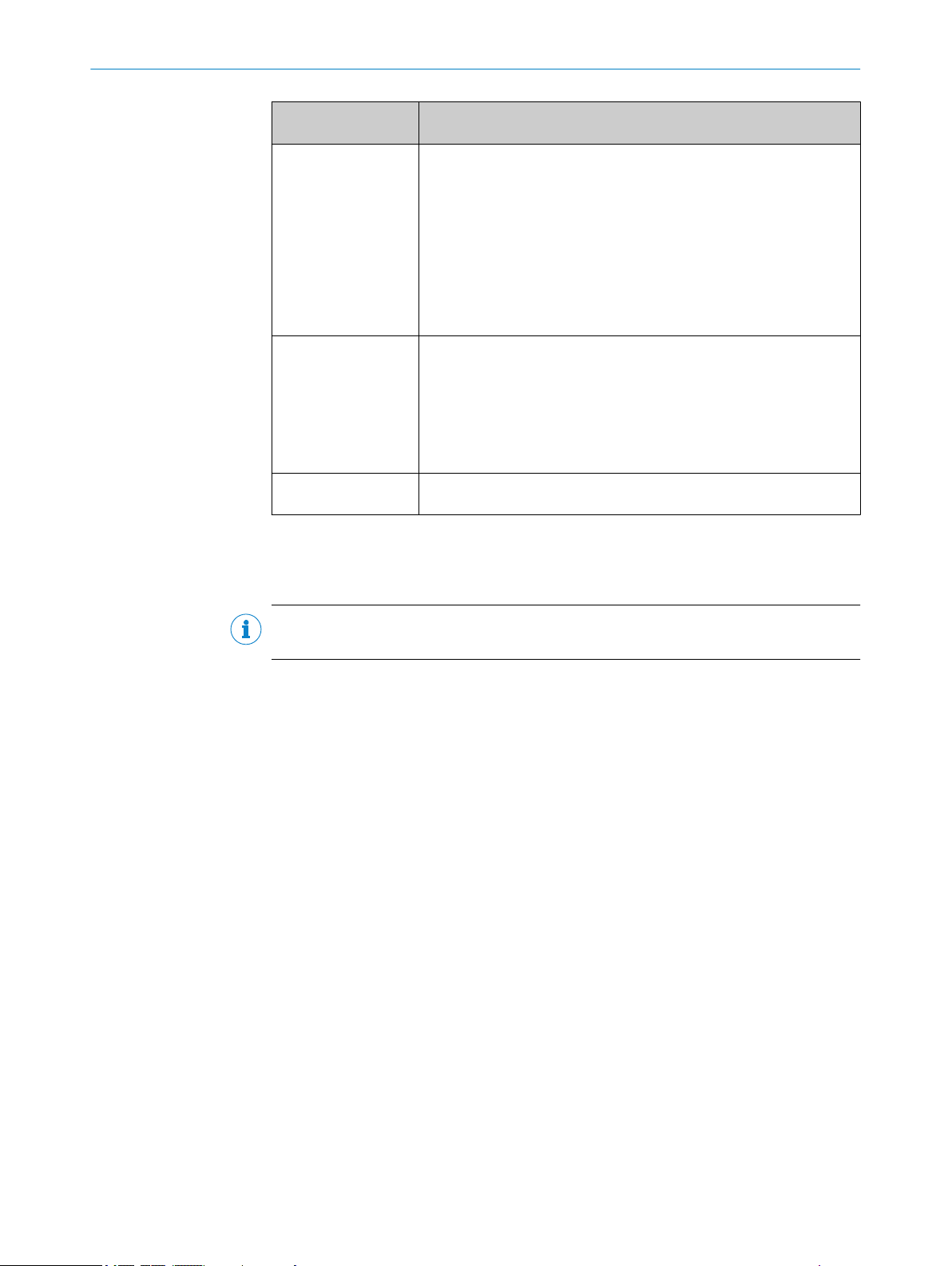
The following qualifications are required for various activities:
Table 1: Activities and technical requirements
Activities Qualification
Mounting, maintenance
Electrical installation,
device replacement
Commissioning, configura‐
tion
Operation of the device for
the particular application
8024536//2019-08-30 | SICK O PE R AT I NG IN S TR U CT I ON S | RFU61x
Subject to change without notice
Basic practical technical training
■
Knowledge of the current safety regulations in the workplace
■
Practical electrical training
■
Knowledge of current electrical safety regulations
■
Knowledge of the operation and control of the devices in their
■
particular application
Basic knowledge of the WindowsTM operating system in use
■
Basic knowledge of the design and setup of the described con‐
■
nections and interfaces
Basic knowledge of data transmission
■
Basic knowledge of RFID technology (identification with radio-
■
based data cards)
Knowledge of the programming of devices
■
Knowledge of the operation and control of the devices in their
■
particular application
Knowledge of the software and hardware environment for the
■
particular application
11
2 SAFETY INFORMATION
2.7 Operational safety and particular hazards
Please observe the safety notes and the warnings listed here and in other chapters of
this product documentation to reduce the possibility of risks to health and avoid dan‐
gerous situations.
WARNING
Electrical voltage!
Electrical voltage can cause severe injury or death.
■
Work on electrical systems must only be performed by qualified electricians.
■
The power supply must be disconnected when attaching and detaching electrical
connections.
■
The product must only be connected to a voltage supply as set out in the require‐
ments in the operating instructions.
■
National and regional regulations must be complied with.
■
Safety requirements relating to work on electrical systems must be complied with.
WARNING
Risk of injury and damage caused by potential equalization currents!
Improper grounding can lead to dangerous equipotential bonding currents, which may
in turn lead to dangerous voltages on metallic surfaces, such as the housing. Electrical
voltage can cause severe injury or death.
■
Work on electrical systems must only be performed by qualified electricians.
■
Follow the notes in the operating instructions.
■
Install the grounding for the product and the system in accordance with national
and regional regulations.
2.8 Repairs
WARNING
Health hazard as a result of high-frequency electromagnetic radiation!
The RFU61x-10600 1) is designed for operation according to ETSI EN 302208. During
operation, the human exposure regulations covered by EN 50364 must be observed.
■
Limit human exposure to electromagnetic fields. Suitable safety distances must be
maintained during both short-term and long-term work in the radiation range of
the integrated antenna.
Minimum distances to be maintained between the antenna and the human body
during long-term transmission: 10 cm and maximum radiation power of the
antenna of 100 mW ERP (20 dBm) pursuant to ETSI.
The RFU61x-10601 2) satisfies the limit values of the FCC for exposure to radiation in
an uncontrolled environment.
■
During operation, a safety distance of at least 20 cm must be maintained between
the antenna and the human body.
Repair work on the device may only be performed by qualified and authorized person‐
nel from SICK AG. Interruptions or modifications to the device by the customer will inval‐
idate any warranty claims against SICK AG.
1)
For regional assignment, see type-specific online data sheet on the Internet at: www.sick.com/RFU61x
2)
For regional assignment, see type-specific online data sheet in the Internet at: www.sick.com/RFU61x
12
O PE R AT I NG IN S TR U CT I ON S | RFU61x 8024536//2019-08-30 | SICK
Subject to change without notice
3 Product description
1
2
3
4
5
6
SICK AG, D-22143 Hamburg
Made in Germany
Manufactured: May 2016
0700
RFU6xx-xxxxx
DC 10...30V <26W
16410240
1062600
Type:
P/N:
MAC:
Power:
S/N:
00:00:00:00:00:00
6
1
2
3
4
5
RFU6xx-xxxx1
DC 12...30V <26W
1620 0001
1054397
Type:
P/N:
MAC:
Power:
S/N:
00:00:00:00:00:00
This device complies with Part 15 of
the FCC rules. Operation is subject to
the following two conditions:
(1) this device may not cause
harmful interference, and
(2) this device must accept any inter ference received, including interference
that may cause undesired operation.
SICK AG, D-22143 Hamburg
Made in Germany
Manufactured: May 2016
Proc. Cont. Eq.
E336916
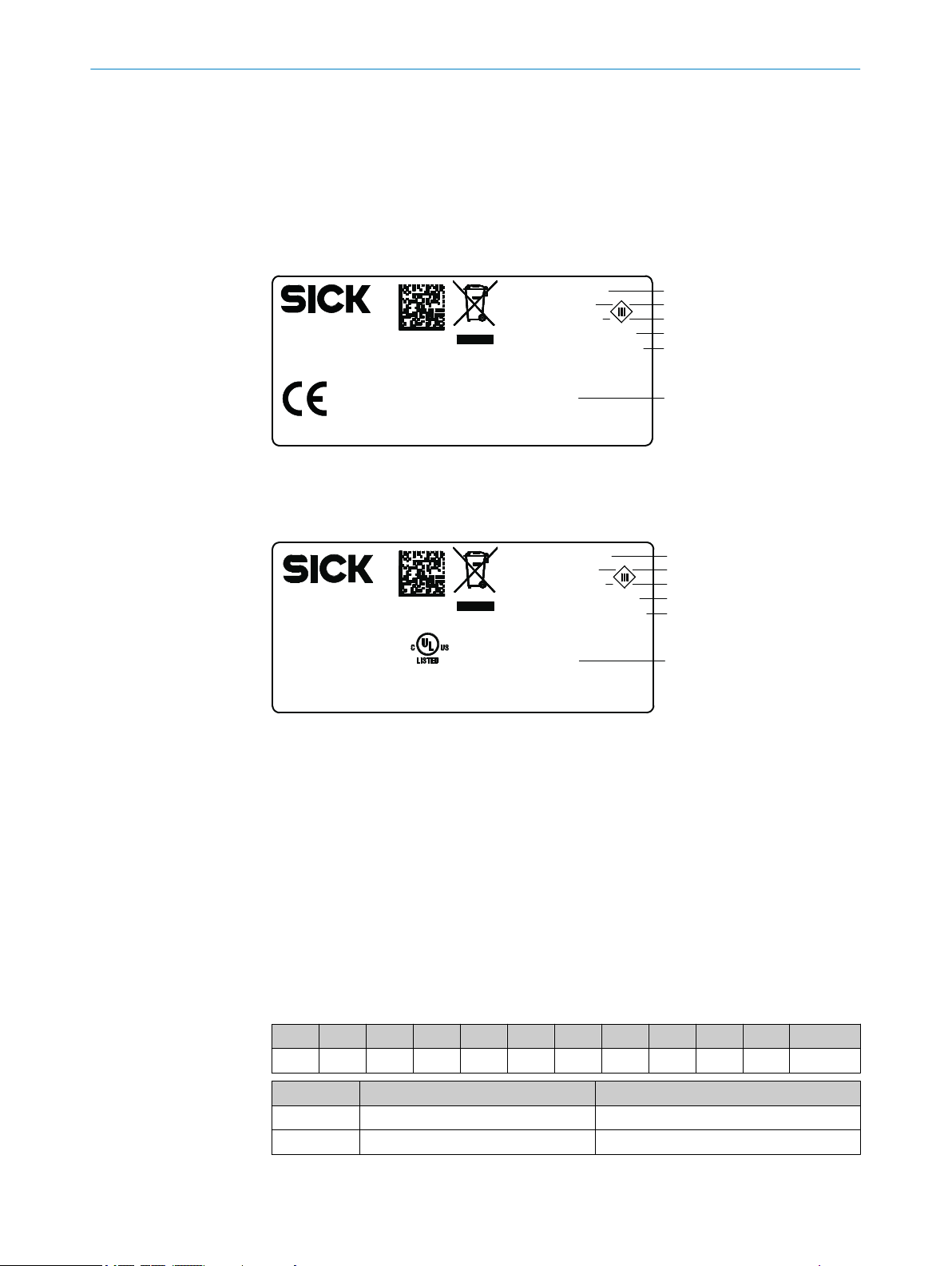
3.1 Product ID
3.1.1 Type label
The type label gives information for identification of the device.
The type labels are located on the underside of the device.
Figure 1: Structure of the type label
The UL certification is dependent on the type. An existing UL certification can be found
on the type label.
PRODUCT DESCRIPTION 3
3.1.2 Type code
8024536//2019-08-30 | SICK O PE R AT I NG IN S TR U CT I ON S | RFU61x
Subject to change without notice
Figure 2: Structure of the type label with UL symbol
Type designation
1
Part number
2
Serial number
3
Supply voltage and power consumption
4
MAC address (placeholder)
5
Approval-related details (region-specific)
6
The devices of the RFU6xx product family are arranged according to the following type
code:
RFUxyz-abcde
R F U x y z - a b c d e
1 2 3 4 5 6 7 8 9 10 11
Position Description Characteristic
1 ... 2 RF (Radio Frequency Identification) –
3 Frequency band U: Ultra High Frequency
13
3 PRODUCT DESCRIPTION
Position Description Characteristic
4 ... 5 Product family or version (working
6 Device type 0: Base type (EPCglobal UHF Class 1 Gen‐
7 Internal antenna 0: No integrated antenna
8 Connections for external antennas 0: No connection
9 Electrical connections 1: 1 x male connector, M12, 17-pin, A-
10 ... 11 Country-specific radio equipment
range)
approval
61: ≤0.5 m (Short Range)
62: ≤2 m (Mid Range)
63: ≤10 m (Long Range)
65: ≤10 m (Long Range)
eration 2, ISO/IEC 18000-6C)
1: With integrated antenna, circularly
polarized
3: 3 connections
4: 4 connections
coded; 1 x female connector, M12, 4-pin,
D-coded
4: Cable 0.9 m with male connector, DSub-HD, 15-pin
5: 1 x female connector, M12, 8-pin, Xcoded
6: 1 x male connector, M12, 4-pin, Acoded, 1 female connector, M8, 4-pin,
coded, 1 x female connector, M12, 8-pin,
X-coded
00: Europe ...
Type-dependent, see type-specific online
data sheet at:
www.sick.com/RFU61x
•
NOTE
Not all combinations are possible according to the type code. The available device vari‐
ants can be found online at:
www.sick.com/RFU61x
•
14
O PE R AT I NG IN S TR U CT I ON S | RFU61x 8024536//2019-08-30 | SICK
Subject to change without notice
3.2 Product characteristics
92 (
3.62
)
1
9
8
94 (
3.70
)
106.4 (
4.19
)
ReadyRFLink/Act
microSD
40 (
1.57
)
16
(
0.63
)
36 (
1.42
)
â
80 (
3.15
) 38 (
1.50
)
12
(
0.47
)
71 (
2.80
)
40 (
1.57
)
5
(
0.20
)
6.4
(
0.25
)
17.5
(
0.69
)
78.8 (
3.10
)
1 3 2
91°
3 (
0.12
)
11.5 (
0.45
)
9.5 (
0.37
)
2
1
4
3
2 3
4 5
ß
á à
6
7
17.5
(
0.69
)
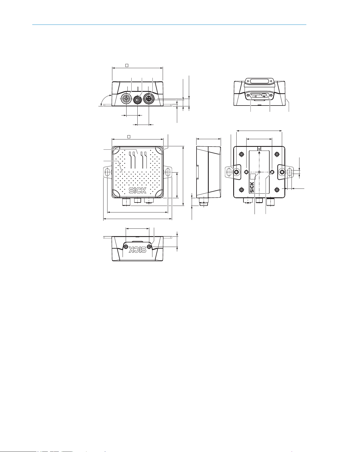
3.2.1 Device view
PRODUCT DESCRIPTION 3
Figure 3: RFU61x-106xx: Structure and dimensions, unit: mm (inch), decimal separator: period
Connection 1: Power (male connector, M12, 4-pin, A-coded)
1
Connection 3: Trigger (female connector, M8, 4-pin, coded)
2
Connection 2: PoE (female connector, M12, 8-pin, X-coded)
3
Slot for microSD memory card
4
“USB” connection (female connector, 5-pin, Micro B type). The USB interface must only be
5
used temporarily as a servicing interface!
Side type label
6
Optics cover with integrated antenna
7
4 x multi-colored LED (status)
8
4 x multi-color LED (process feedback)
9
2 x M5 threaded mounting holes, 6 mm deep, for attaching the mounting straps
ß
2 x M5 blind tapped holes, 7 mm deep, for alternative mounting of the device
à
type label with integrated pressure compensation membrane
á
2 x screw (M2,5 socket screw), captive, for side cover
â
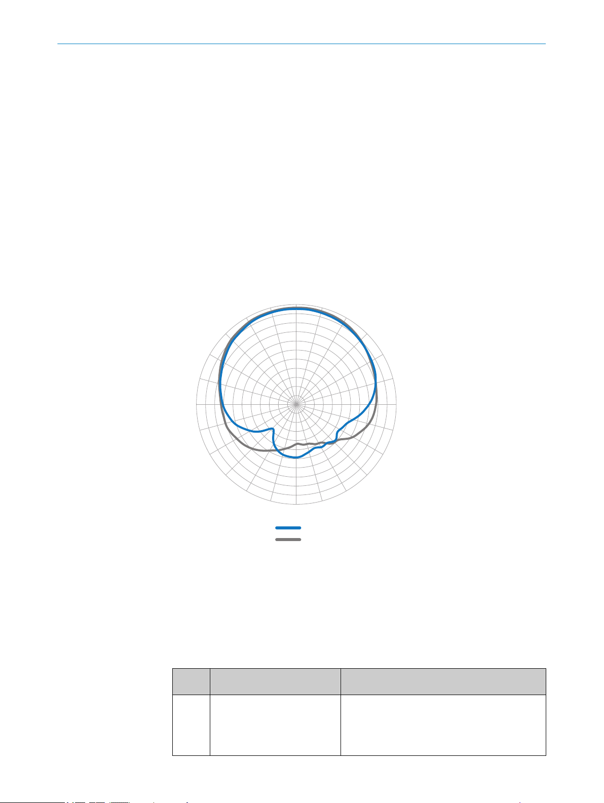
3.2.2 Working range of the antenna
8024536//2019-08-30 | SICK O PE R AT I NG IN S TR U CT I ON S | RFU61x
Subject to change without notice
Sensing range of the reading and writing field
The environment influences the UHF field of the integrated antenna, making it impossi‐
ble to provide a “clear” demarcation of the sensing range.
15
–33
–30
–27
–24
–21
–18
–15
–12
–9
–6
–3
0°
15°
30°
45°
60°
75°
90°
105°
120°
135°
150°
165°
180°
–165°
–150°
–135°
–120°
–105°
–90°
–75°
–60°
–45°
–30°
–15°
2
1
0
3 PRODUCT DESCRIPTION
•
•
In addition to the read results, the RFU device can also output diagnostic data that pro‐
vide an indication of the write and read quality. This data can be used to achieve opti‐
mum read results when setting up the system.
The radiation pattern shown here for the device’s antenna was obtained in a repro‐
ducible environment (absorber chamber as a reflection-free space) for illustrative pur‐
poses. The diagram may therefore only have limited applicability to your specific appli‐
cation. The diagram shows how the UHF field propagates in a reflection-free space, but
cannot be used on-site to draw any conclusions on the likely sensing range in a real
application.
Application-specific reflections can result in both overreaches and “holes”
(destructive interferences).
Other factors that can significantly impact the sensing range include:
Quality of the transponder. The quality depends on the antenna gain, the inte‐
°
grated transponder IC and its sensitivity, the reflected energy.
Material of the carrier object (plastic, wood, metal)
°
Objects between the device and transponder that can affect the UHF field
°
(items, liquids, people)
3.2.3 Scope of delivery
16
O PE R AT I NG IN S TR U CT I ON S | RFU61x 8024536//2019-08-30 | SICK
Figure 4: Radiation pattern of the integrated antenna of the RFU61x (typical): Measured antenna
gain in dBic at 866.5 MHz, LHCP (left-hand circularly polarized)
Horizontal plane (azimuth)
1
Vertical plane (elevation)
2
The delivery of the device includes the following components:
Table 2: RFU61x: scope of delivery
No. of
units
1 Device in the version ordered
Component Notes
RFU61x-106xx
(region assignment)
The M12 and M8 electrical connections sealed with
tightly-fastened protective plugs or caps.
The joint side cover for the USB interface and the
memory card slot is closed and screwed tight.
Subject to change without notice
PRODUCT DESCRIPTION 3
No. of
units
1 Mounting kit, consisting of
Component Notes
Fastening clamps, protruding after mounting for fas‐
2 x mounting strap
•
2 x countersunk head screw
•
with hexagon socket, M5 x 8
Printed Quick Start Guide, num‐
ber of language versions depen‐
dent on region.
tening the device from the front at both sides. Alter‐
natively for mounting from the rear: 2 M5 threaded
mounting holes on the rear of the device.
All available language versions of the Quick Start
Guide can also be found online as PDFs at:
www.sick.com/RFU61x
•
The following associated components are not included in the delivery. The components
are available on the Internet.
Table 3: RFU61x: Other components
Component Notes
SOPAS ET configuration software and
device description file (*.sdd-file) for the
RFU61x
RFU61x operating instructions as PDF in
English, French and German. Other lan‐
guages are available online where applic‐
able.
RFU parameter description as PDF in Eng‐
lish and German.
Available online at:
www.sick.com/SOPAS_ET
•
Available online at:
www.sick.com/RFU61x
•
Accessories
The following accessories for constructing a complete RFID read/write station are not
included in the scope of delivery of the device. If required, order accessories separately.
Read cycle trigger sensor, e.g. photoelectric retro-reflective sensor for object-spe‐
•
cific triggering
Suitable number of transponders depending on the application
•
3.2.4 Product features and functions (overview)
NOTE
In addition to the existing operating instructions, the use of the RFU parameter descrip‐
tion is recommended:
This parameter description explains the UHF-RFID-specific parameters of all
•
device variants of the RFU6xx product family up to and including the “Service”
user level.
The parameter description supports the user in configuring applications with the
•
SOPAS ET configuration software.
The parameter description is available in English (part no. 8023085) and German (part
no. 8023084) as well as other languages if required.
The RFU parameter description can be found on the online product page at:
www.sick.com/RFU61x
•
8024536//2019-08-30 | SICK O PE R AT I NG IN S TR U CT I ON S | RFU61x
Subject to change without notice
17
3 PRODUCT DESCRIPTION
Table 4: Overview of product features and functions of the device
Product feature/func‐
tion
Security and ease of
use
Convenient operation/
configuration
Reading Operation
Mode
Read cycle
Radio interface(s)
Transponder Process‐
ing
Transponder Manage‐
ment
Data processing
Characteristic
Rugged, compact metal housing, CE marking (Europe)
•
Automatic self-test at system start
•
Diagnostic tools for device setup and (remote) device monitoring
•
Configurable output of the read results including read diagnostics
•
data in two output formats
Operating data request. In the event of an error: output of codified
•
error messages on request
Test string function (heartbeat) can be activated to signal that the
•
device is ready for operation
Future-proof due to firmware update via data interface
•
Future-proof SOPAS ET configuration software with password-pro‐
•
tected configuration mode
SICK AppSpace ready: The device already includes SensorApp for
•
integrating it into existing communication networks
Low power consumption
•
Wide supply voltage range. Supply via separate power source or
•
PoE.
Large ambient temperature range. For details, see "Technical data",
•
page 61
Parameter cloning (to back up the configuration data in the internal
•
device memory):
By pluggable microSD memory card 1) externally in the device
°
Configuration (online or offline) using SOPAS ET configuration soft‐
•
ware
Single Tag ID Wizard (assistant) to help with initial configuration
•
Configuration and starting of device functions via a web server
•
(SOPASair) or command strings
Optional function blocks for easier integration into PLC programs
•
PROFINET single port : Configuration via GSD parameterization
•
Application-specific programming is possible using the SICK AppStu‐
•
dio development environment.
You can find further information on the Internet at: www.sick.com/
SICK_AppStudio
Status and process feedback indicators via LEDs
•
Start/stop operation: For reading one or more transponders during
•
a read cycle.
Start and stop conditions of the read cycle can be configured in the
•
object trigger control: digital input
Integrated antenna
•
Base model RFU610 supports all standard passive transponders
•
that are compatible with EPCglobal UHF Class 1 Generation 2 or
ISO/IEC-18000-6C
Reading, writing, and multiple overwriting of the data on the
•
transponders, depending on the application
Within a process chain, the device supplying the data is a partial
•
component for the complete visualization of data
Decoding of the UII in HEX, BIN and ASCII. Supports GS1 TDS and
•
other industry-specific standards such as VDA55xx.
Variable read data output based on event-dependent evaluation
•
conditions
Influencing the output string by filtering and output sorting
•
Implementation of application-specific data output protocols using
•
the SICK AppStudio development environment (flexible back-end
integration)
18
O PE R AT I NG IN S TR U CT I ON S | RFU61x 8024536//2019-08-30 | SICK
Subject to change without notice
PRODUCT DESCRIPTION 3
Product feature/func‐
tion
Data communication Host interface
Electrical Interfaces
Connectivity (Design)
1)
Optional accessories.
2)
USB interface must only be used temporarily as a servicing interface!
Characteristic
Two data output formats configurable.
•
The output is switchable to different physical or logical interfaces.
•
Parallel operation is possible. For outputting the data to a furtherprocessing computer.
Aux interface
Fixed data output format.
•
The output is switchable to different physical or logical interfaces.
•
For the device configuration and diagnostics as well as the
transponder access.
Host interface
•
Ethernet (supported protocols include, amongst others,
°
PROFINET single port).
Aux interface
•
Ethernet, USB
°
1 digital input for external trigger sensor
•
Voltage supply (power or PoE)
•
RFU61x-106xx: 2 x M12 male circular connector, 1 x M8 male circu‐
•
lar connector, 1 x USB (Micro B type)
2)
3.2.5 Memory card
NOTE
The memory card is an optional accessory and is not included in the scope of delivery.
Functions
The device can execute the following functions on the plug-in microSD memory card:
Saving the parameter set (cloning function)
•
Semi-automatic, additional storage of the internal parameter set (device configura‐
tion data) on an external memory medium. This takes place in the framework of
the recommended backup concept for the 4Dpro device parameter sets.
This function is initiated by using the “permanent” option to save the internal
°
parameter set, e.g. via the SOPAS ET configuration software.
The function is used, among other things, to conveniently transfer the para‐
°
meter set to an replacement device of the same type in the event of an fault.
A MicroSD memory card that can be plugged into the device serves as an
°
optional, external medium
Recording of diagnostic read data
•
Continuous recording of diagnostic read data after the first manual start, e.g., via
SOPAS ET. Recording is resumed after a device restart if the function has been
permanently set.
Other functions on request.
•
We recommend using an empty memory card when storing a parameter set for the first
time (if necessary, use a PC and card reader to check and delete the contents of the
card).
8024536//2019-08-30 | SICK O PE R AT I NG IN S TR U CT I ON S | RFU61x
Subject to change without notice
19
1
2 3
PRODUCT DESCRIPTION
3
NOTE
Only use types approved by SICK to ensure reliable function of the memory card. You
can find these as accessories online at:
www.sick.com/RFU61x
•
The memory card has no write protection that can be activated.
Indication of operational readiness
The “microSD” optical indicator shows the status of the memory card after installation
in the device. It lights up in different colors according to the status, see "Optical status
indicators on the display panel", page 51.
NOTICE
Possible data loss!
When the indicator is green (operational), this does not mean that the device is actually
accessing the memory card for reading or writing.
Do not remove the memory card or switch off the supply voltage while the follow‐
b
ing functions are taking place in the device via the SOPAS ET configuration soft‐
ware:
■
Saving the parameter values using the “permanent” option
■
Starting functions that access the memory card (e.g. concurrent logging of
data)
Inserting the memory card in the device:
NOTICE
Risk of damage to the memory card!
To safely install the memory card, make sure there is no power to the device
b
before you insert it.
Ensure the IP67 enclosure rating of the device is maintained see "Conditions for speci‐
fied enclosure rating", page 10.
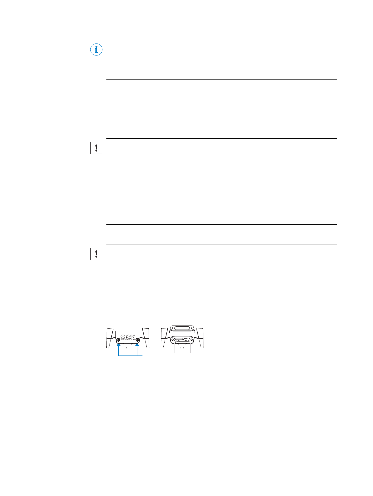
The card slot on the device is located under the cover foil on the side opposite the elec‐
trical connections.
Figure 5: Slot for MicroSD memory card and “USB” connection
2 x screw, M2.5 hexagon socket
1
Slot for microSD memory card
2
“USB” connection (female connector, 5-pin, Micro B type)
3
1. Switch off the supply voltage to the device.
2. Loosen both screws on the cover.
3. Carefully fold up the cover.
4. Making sure it is in the correct position, insert the memory card into the slot until
it locks into place. When doing so, orient the contacts so that they are facing
towards the device and downwards as per the symbol on the device.
20
O PE R AT I NG IN S TR U CT I ON S | RFU61x 8024536//2019-08-30 | SICK
Subject to change without notice
PRODUCT DESCRIPTION 3
5. Screw the cover back on. Recommended tightening torque for the cover screws:
30 Ncm ± 5 Ncm.
6. Switch on the supply voltage for the device.
Interpretation of the stored parameter set
Once it is switched on, the device automatically detects the presence of a memory card
and, depending on the card’s content, behaves as follows:
■
If the memory card is empty or if does not contain a parameter set that can be
interpreted by the device: the device saves its currently valid internal parameter
set to the card (provided there is sufficient storage space) and starts with the
internal parameter set.
■
If the card contains a parameter set that can be interpreted by the device: the
device overwrites the currently valid internal parameter set with this external para‐
meter set.
The goal is for the internal parameter set and the parameter set saved externally to
always be identical.
Removing the memory card from the device:
NOTICE
Risk of damage to the memory card!
To safely remove the memory card while the device is in operation:
b
In SOPAS ET, execute the Remove SD card command under Analysis/SD card and
°
wait for SOPAS ET to provide confirmation.
If this command is not accessible, the memory card can also be removed
°
when there is no power to the device.
8024536//2019-08-30 | SICK O PE R AT I NG IN S TR U CT I ON S | RFU61x
Subject to change without notice
21
 Loading...