

Page 1

RFU61x
RFID read/write device (UHF)
O P E R A T I N G I N S T R U C T I O N S
Page 2

Described product
RFU610-106xx
Manufacturer
SICK AG
Erwin-Sick-Str. 1
79183 Waldkirch
Germany
Legal information
This work is protected by copyright. Any rights derived from the copyright shall be
reserved for SICK AG. Reproduction of this document or parts of this document is only
permissible within the limits of the legal determination of Copyright Law. Any modifica‐
tion, abridgment or translation of this document is prohibited without the express writ‐
ten permission of SICK AG.
The trademarks stated in this document are the property of their respective owner.
© SICK AG. All rights reserved.
Original document
This document is an original document of SICK AG.
Conformities
Due to the country-specific approvals for the device, the respective conformance infor‐
mation is type-dependent. For the specific device that you have, see the online typespecific data sheet at:
www.sick.com/RFU61x
•
The type designation of your device can be found on the type label.
The trademarks mentioned in this document are the property of the respective owners.
2
O PE R AT I NG IN S TR U CT I ON S | RFU61x 8024536//2019-08-30 | SICK
Subject to change without notice
Page 3

Contents
CONTENTS
1 About this document........................................................................ 5
1.1 Information on the operating instructions.............................................. 5
1.2 Scope......................................................................................................... 5
1.3 Explanation of symbols............................................................................ 6
1.4 Further information................................................................................... 7
1.5 SICK service.............................................................................................. 7
2 Safety information............................................................................ 8
2.1 Intended use............................................................................................. 8
2.2 Improper use............................................................................................. 9
2.3 Internet protocol (IP) technology.............................................................. 9
2.4 Limitation of liability................................................................................. 9
2.5 Modifications and conversions................................................................ 10
2.6 Requirements for skilled persons and operating personnel.................. 11
2.7 Operational safety and particular hazards.............................................. 12
2.8 Repairs...................................................................................................... 12
3 Product description........................................................................... 13
3.1 Product ID.................................................................................................. 13
3.2 Product characteristics............................................................................ 15
4 Transport and storage....................................................................... 22
4.1 Transport................................................................................................... 22
4.2 Unpacking.................................................................................................. 22
4.3 Transport inspection................................................................................. 22
4.4 Storage...................................................................................................... 22
5 Mounting............................................................................................. 24
5.1 Overview of mounting procedure............................................................. 24
5.2 Preparation for mounting......................................................................... 24
5.3 Mounting location..................................................................................... 26
5.4 Mounting the device................................................................................. 27
5.5 Mounting external components............................................................... 28
6 Electrical installation........................................................................ 30
6.1 Safety......................................................................................................... 30
6.2 Wiring instructions.................................................................................... 34
6.3 Overview of all interfaces and connection options................................ 35
6.4 Pin assignments of electrical connections............................................. 39
6.5 Instructions for electrical installation when the ambient temperature
can fall below 0 °C................................................................................... 40
6.6 Installation steps...................................................................................... 41
6.7 Connecting the supply voltage................................................................. 43
6.8 Wiring the digital input............................................................................. 45
6.9 Wiring the data interface.......................................................................... 46
8024536//2019-08-30 | SICK O PE R AT I NG IN S TR U CT I ON S | RFU61x
Subject to change without notice
3
Page 4

CONTENTS
7 Commissioning.................................................................................. 47
7.1 Overview of the Commissioning Steps.................................................... 47
7.2 SOPAS ET configuration software............................................................ 47
7.3 Starting the SOPAS ET configuration software and connecting it to
the device.................................................................................................. 48
7.4 Initial commissioning................................................................................ 49
8 Operation............................................................................................ 51
8.1 Operating and status indicators.............................................................. 51
9 Maintenance...................................................................................... 55
9.1 Maintenance plan..................................................................................... 55
9.2 Cleaning..................................................................................................... 55
10 Troubleshooting................................................................................. 56
10.1 Overview of Potential Errors and Faults.................................................. 56
10.2 Detailed fault analysis.............................................................................. 56
10.3 Status log.................................................................................................. 57
10.4 SICK service.............................................................................................. 57
10.5 Repairs...................................................................................................... 57
10.6 Returns...................................................................................................... 57
10.7 Replacing the device................................................................................ 58
11 Decommissioning............................................................................. 60
11.1 Disposal..................................................................................................... 60
12 Technical data.................................................................................... 61
12.1 Features.................................................................................................... 61
12.2 Interfaces.................................................................................................. 62
12.3 Mechanics and electronics...................................................................... 62
12.4 Ambient data............................................................................................. 63
12.5 Working range diagram............................................................................ 63
12.6 Dimensional drawing................................................................................ 63
13 Accessories........................................................................................ 64
14 Annex.................................................................................................. 65
14.1 EU declaration of conformity / Certificates............................................. 65
14.2 Certification according to UL61010-1..................................................... 65
14.3 Signal assignment of cables with open cable end at one end.............. 65
14.4 Copyright notices...................................................................................... 66
14.5 Abbreviations used................................................................................... 66
4
O PE R AT I NG IN S TR U CT I ON S | RFU61x 8024536//2019-08-30 | SICK
Subject to change without notice
Page 5

1 About this document
1.1 Information on the operating instructions
These operating instructions provide important information on how to use devices from
SICK AG.
Prerequisites for safe work are:
Compliance with all safety notes and handling instructions supplied.
•
Compliance with local work safety regulations and general safety regulations for
•
device applications
The operating instructions are intended to be used by qualified personnel and electrical
specialists.
NOTE
Read these operating instructions carefully to familiarize yourself with the device and its
functions before commencing any work.
The operating instructions are an integral part of the product. Store the instructions in
the immediate vicinity of the device so they remain accessible to staff at all times.
Should the device be passed on to a third party, these operating instructions should be
handed over with it.
ABOUT THIS DOCUMENT
1
1.2 Scope
These operating instructions do not provide information on operating the machine or
system in which the device is integrated. For information about this, refer to the operat‐
ing instructions of the specific machine.
These operating instructions serve to incorporate the device into a customer system.
These operating instructions form part of the documentation provided to users. The
operating instructions supplement the Quick Start Guide with more detailed and addi‐
tional information. The Quick Start guide for initial commissioning is enclosed with the
devices in printed form. The Quick Start guide can also be downloaded from the follow‐
ing website:
www.sick.com/RFU61x
•
The operating instructions provide in-depth information on the following topics:
Interpreting the type code
•
Overview of product features and functions of the device
•
Scope of delivery of the device: enclosed components, required online access to
•
additional components
Operation of the device in an ambient temperature range below 0 °C: measures
•
and requirements for mounting and electrical installation
Applications with spatially distributed systems: measures to prevent possible
•
ground potential equalizing currents
Overview of all interfaces and connection options for the device
•
Wiring the individual interfaces of the device
•
Additional functions of the status indicators
•
Overview of operating options and available configuration tools for the device
•
Measures for eliminating interference
•
Step-by-step procedures are given for all required actions in the operating instructions.
These instructions apply to all available device variants of the product. Functions spe‐
cific to special devices are, where necessary, described in additional documents.
8024536//2019-08-30 | SICK O PE R AT I NG IN S TR U CT I ON S | RFU61x
Subject to change without notice
5
Page 6
1 ABOUT THIS DOCUMENT
More detailed information for identification of the available device type see "Type code",
page 13.
The available device variants, and information about the regionally related radio equip‐
ment approvals are listed on the online product page:
•
Commissioning is described in the operating instructions using one particular device
variant as an example. Commissioning is based on the basic parameter setting of the
device. Reading a transponder on an object serves as the basis for the simple applica‐
tion.
NOTE
The device approval was granted for a specific region. The region assignment cannot be
changed.
•
•
•
•
www.sick.com/RFU61x
Only use the device in the region for which it has been approved.
When reselling the device, inform the buyer of the fixed region assignment.
Should the device be passed on to a third party, these operating instructions and
the Quick Start Guide should be handed over with it.
For country-specific special features in the operation of the device, see “Operating
restrictions” in the Quick Start Guide. A printed copy of the Quick Start Guide is
supplied with the device. The Quick Start Guide can also be accessed in PDF for‐
mat on the device product page on the Internet at: www.sick.com/RFU61x.
1.3 Explanation of symbols
Warnings and important information in this document are labeled with symbols. Signal
words introduce the instructions and indicate the extent of the hazard. To avoid acci‐
dents, damage, and personal injury, always comply with the instructions and act care‐
fully.
DANGER
… indicates a situation of imminent danger, which will lead to a fatality or serious
injuries if not prevented.
WARNING
… indicates a potentially dangerous situation, which may lead to a fatality or serious
injuries if not prevented.
CAUTION
… indicates a potentially dangerous situation, which may lead to minor/slight injuries if
not prevented.
NOTICE
… indicates a potentially harmful situation, which may lead to material damage if not
prevented.
NOTE
… highlights useful tips and recommendations as well as information for efficient and
trouble-free operation.
6
O PE R AT I NG IN S TR U CT I ON S | RFU61x 8024536//2019-08-30 | SICK
Subject to change without notice
Page 7

1.4 Further information
NOTE
Further documentation for the device can be found on the online product page at:
www.sick.com/RFU61x
•
There, additional information has been provided depending on the product, such as:
Model-specific online data sheets for device variants, containing technical data,
•
dimensional drawing, and specification diagrams
EU declarations of conformity for the product family
•
Certificates of the product family
•
Dimensional drawings and 3D CAD dimension models of the device variants in var‐
•
ious electronic formats
Quick Start guides for initial commissioning of the device
•
This documentation, available in English and German, and in other languages if
•
necessary
Other publications related to the devices described here
•
Publications dealing with accessories
•
NOTE
In addition to the existing operating instructions, the use of the RFU parameter descrip‐
tion is recommended. This document explains the UHF-RFID-specific parameters of all
device variants of the RFU6xx product family at the "Service” user level.
The parameter description supports the user in configuring applications with the
SOPAS ET configuration software.
ABOUT THIS DOCUMENT 1
1.5 SICK service
If you require any technical information, our SICK Service will be happy to help. To find
your agency, see the final page of this document.
NOTE
Before calling, make a note of all type label data such as type code, serial number, etc.,
to ensure faster processing.
8024536//2019-08-30 | SICK O PE R AT I NG IN S TR U CT I ON S | RFU61x
Subject to change without notice
7
Page 8

2 SAFETY INFORMATION
2 Safety information
2.1 Intended use
The RFU61x RFID read/write device is an intelligent ID sensor from the SICK RFU6xx
(UHF) product family. Version (working range): Short Range.
The device is used for the automated, fixed identification of wireless-based data cards
(transponders) on moving or stationary objects, and for the management of these data
cards. The RFU610 base model processes all standard passive transponders in accor‐
dance with EPCglobal UHF C1G2 and ISO/IEC 18000-6C in the regional UHF carrier fre‐
quency range.
The device works in stand-alone operation. In read mode, the device transmits the
results via a host interface to a higher-level computer (e.g. PLC) for further centralized
processing. Network operation is possible for coordinating trouble-free readings of
devices at close proximity to one another, but without a coordinating summary of the
reading results by one of the devices involved.
The compact device contains an antenna integrated in the housing.
The device allows operation within a wide ambient temperature range. For details, see
"Technical data", page 61.
The device is primarily designed for use in industrial and logistics areas, and meets the
requirements for industrial ruggedness, interfaces and data processing. If necessary,
the device can be programmed to implement customer-specific modifications.
NOTE
The USB interface of the device is used in industrial environments only as a service
interface for temporary use (e.g. for configuration, troubleshooting). Permanent use in
operational use of the system as a host interface is not intended.
SICK AG assumes no liability for losses or damage arising from the use of the product,
either directly or indirectly. This applies in particular to use of the product that does not
conform to its intended purpose and is not described in this documentation.
2.1.1 Operational restrictions
NOTICE
Operational restrictions!
The frequency band of the device is configured for the specific type and region when
delivered. This enables the device to be operated in the respective approved region
without interfering with protected frequencies (such as mobile communications).
Operating the device in other regions, however, can interfere with protected frequen‐
cies.
■
Only use the device in the region for which it has been approved.
■
When reselling the device, inform the buyer of the fixed region assignment.
■
Should the device be passed on to a third party, these operating instructions and
the Quick Start Guide should be handed over with it.
■
For further country-specific operating requirements, see the Quick Start Guide, a
printed copy of which is enclosed with the device or can be downloaded online
(PDF) at:
°
www.sick.com/RFU61x
A region consists either of a group of countries or of only one country.
8
O PE R AT I NG IN S TR U CT I ON S | RFU61x 8024536//2019-08-30 | SICK
Subject to change without notice
Page 9
2.1.2 Regulatory notes
Europe: simplified EU declaration of conformity
SICK AG hereby declares that the RFU61x-106xx radio equipment complies with the
2014/53/EU directive. The complete text of the EU declaration of conformity is avail‐
able at the following web address:
•
2.2 Improper use
Any use outside of the stated areas, in particular use outside of the technical specifica‐
tions and the requirements for intended use, will be deemed to be incorrect use.
•
•
•
WARNING
Danger due to improper use!
Any improper use can result in dangerous situations.
Therefore, observe the following information:
■
■
SAFETY INFORMATION 2
www.sick.com/RFU61x
The device does not constitute a safety component in accordance with the respec‐
tive applicable safety standards for machines.
The device must not be used in explosion-hazardous areas, in corrosive environ‐
ments or under extreme environmental conditions.
Any use of accessories not specifically approved by SICK AG is at your own risk.
Device should be used only in accordance with its intended use.
All information in these operating instructions must be strictly observed.
2.3 Internet protocol (IP) technology
NOTE
SICK uses standard IP technology in its products. The emphasis is placed on availability
of products and services.
SICK always assumes the following prerequisites:
The customer ensures the integrity and confidentiality of the data and rights
•
affected by its own use of the aforementioned products.
In all cases, the customer implements the appropriate security measures, such as
•
network separation, firewalls, virus protection, and patch management.
2.4 Limitation of liability
Relevant standards and regulations, the latest technological developments, and our
many years of knowledge and experience have all been taken into account when com‐
piling the data and information contained in these operating instructions. The manufac‐
turer accepts no liability for damage caused by:
■
Failing to observe the operating instructions
■
Incorrect use
■
Use of untrained staff
■
Unauthorized conversions
■
Technical modifications
■
Use of unauthorized spare parts, consumables, and accessories
With special variants, where optional extras have been ordered, or owing to the latest
technical changes, the actual scope of delivery may vary from the features and illustra‐
tions shown here.
8024536//2019-08-30 | SICK O PE R AT I NG IN S TR U CT I ON S | RFU61x
Subject to change without notice
9
Page 10
2 SAFETY INFORMATION
NOTE
The product is a programmable device. The respective programmer is therefore respon‐
sible for his/her programming work and the resultant operation of the device. The liabil‐
ity and warranty of SICK AG is limited to the device specification (hardware functionality
and any programming interfaces) according to the agreed conditions. SICK AG will
therefore not be liable, among other things, for any damages resulting from the pro‐
gramming of the product by the customer or third parties.
2.5 Modifications and conversions
NOTICE
Modifications and conversions to the device may result in unforeseeable dangers.
Interrupting or modifying the device or SICK software will invalidate any warranty claims
against SICK AG. This applies in particular to opening the housing, even as part of
mounting and electrical installation.
2.5.1 Exception: temporarily opening the cover on the device
NOTICE
The user may open the housing only in order to obtain temporary access to the USB
interface or the slot for the optional memory card. For this purpose, the corresponding
side cover on the device can be opened temporarily.
In open state, the device does not conform to a specified enclosure rating. The device
must be protected appropriately against moisture and dust.
Operate the device only for a short time without closed cover.
b
NOTE
The USB interface of the device is used in industrial environments only as a service
interface for temporary use (e.g. for configuration, troubleshooting). Permanent use in
operational use of the system as a host interface is not intended.
For further warranty provisions, see the General Terms and Conditions of SICK AG, e.g.
on the delivery note of the device.
2.5.2 Conditions for specified enclosure rating
To ensure compliance with the specified IP67 enclosure rating of the device, the follow‐
ing requirements must be met. If these requirements are not met, the device does not
fulfill any specified enclosure rating.
The joint side cover for the USB interface and the memory card slot is placed
•
against the device and screwed on tight.
The cables plugged into the electrical M12 and M8 connections must be screwed
•
tight.
Any M12 and M8 connections that are not being used must be sealed with protec‐
•
tive plugs or caps, depending on type. These plugs or caps must be screwed tight
(as in the delivery condition).
The same also applies to the EMC requirement (ESD) according to CE.
10
NOTICE
The type label on the lower side of the device contains a pressure equalizing membrane
attached in the middle. If the type label is damaged or removed, the leak tightness of
the device can no longer be guaranteed.
O PE R AT I NG IN S TR U CT I ON S | RFU61x 8024536//2019-08-30 | SICK
Subject to change without notice
Page 11
Positions of the individual elements see "Device view", page 15
NOTICE
The device can, if necessary, be operated for a short time without the side cover to per‐
form the following tasks:
Inserting or removing the optional memory card
•
Temporary use of the USB interface as a servicing interface
•
During this time, protect the device against moisture and dust.
2.6 Requirements for skilled persons and operating personnel
WARNING
Risk of injury due to insufficient training.
Improper handling of the device may result in considerable personal injury and material
damage.
■
All work must only ever be carried out by the stipulated persons.
This product documentation refers to the following qualification requirements for the
various activities associated with the device:
■
Instructed personnel have been briefed by the operator about the tasks assigned
to them and about potential dangers arising from improper action.
■
Skilled personnel have the specialist training, skills, and experience, as well as
knowledge of the relevant regulations, to be able to perform tasks delegated to
them and to detect and avoid any potential dangers independently.
■
Electricians have the specialist training, skills, and experience, as well as knowl‐
edge of the relevant standards and provisions to be able to carry out work on elec‐
trical systems and to detect and avoid any potential dangers independently. In Ger‐
many, electricians must meet the specifications of the BGV A3 Work Safety Regu‐
lations (e.g. Master Electrician). Other relevant regulations applicable in other
countries must be observed.
SAFETY INFORMATION 2
The following qualifications are required for various activities:
Table 1: Activities and technical requirements
Activities Qualification
Mounting, maintenance
Electrical installation,
device replacement
Commissioning, configura‐
tion
Operation of the device for
the particular application
8024536//2019-08-30 | SICK O PE R AT I NG IN S TR U CT I ON S | RFU61x
Subject to change without notice
Basic practical technical training
■
Knowledge of the current safety regulations in the workplace
■
Practical electrical training
■
Knowledge of current electrical safety regulations
■
Knowledge of the operation and control of the devices in their
■
particular application
Basic knowledge of the WindowsTM operating system in use
■
Basic knowledge of the design and setup of the described con‐
■
nections and interfaces
Basic knowledge of data transmission
■
Basic knowledge of RFID technology (identification with radio-
■
based data cards)
Knowledge of the programming of devices
■
Knowledge of the operation and control of the devices in their
■
particular application
Knowledge of the software and hardware environment for the
■
particular application
11
Page 12
2 SAFETY INFORMATION
2.7 Operational safety and particular hazards
Please observe the safety notes and the warnings listed here and in other chapters of
this product documentation to reduce the possibility of risks to health and avoid dan‐
gerous situations.
WARNING
Electrical voltage!
Electrical voltage can cause severe injury or death.
■
Work on electrical systems must only be performed by qualified electricians.
■
The power supply must be disconnected when attaching and detaching electrical
connections.
■
The product must only be connected to a voltage supply as set out in the require‐
ments in the operating instructions.
■
National and regional regulations must be complied with.
■
Safety requirements relating to work on electrical systems must be complied with.
WARNING
Risk of injury and damage caused by potential equalization currents!
Improper grounding can lead to dangerous equipotential bonding currents, which may
in turn lead to dangerous voltages on metallic surfaces, such as the housing. Electrical
voltage can cause severe injury or death.
■
Work on electrical systems must only be performed by qualified electricians.
■
Follow the notes in the operating instructions.
■
Install the grounding for the product and the system in accordance with national
and regional regulations.
2.8 Repairs
WARNING
Health hazard as a result of high-frequency electromagnetic radiation!
The RFU61x-10600 1) is designed for operation according to ETSI EN 302208. During
operation, the human exposure regulations covered by EN 50364 must be observed.
■
Limit human exposure to electromagnetic fields. Suitable safety distances must be
maintained during both short-term and long-term work in the radiation range of
the integrated antenna.
Minimum distances to be maintained between the antenna and the human body
during long-term transmission: 10 cm and maximum radiation power of the
antenna of 100 mW ERP (20 dBm) pursuant to ETSI.
The RFU61x-10601 2) satisfies the limit values of the FCC for exposure to radiation in
an uncontrolled environment.
■
During operation, a safety distance of at least 20 cm must be maintained between
the antenna and the human body.
Repair work on the device may only be performed by qualified and authorized person‐
nel from SICK AG. Interruptions or modifications to the device by the customer will inval‐
idate any warranty claims against SICK AG.
1)
For regional assignment, see type-specific online data sheet on the Internet at: www.sick.com/RFU61x
2)
For regional assignment, see type-specific online data sheet in the Internet at: www.sick.com/RFU61x
12
O PE R AT I NG IN S TR U CT I ON S | RFU61x 8024536//2019-08-30 | SICK
Subject to change without notice
Page 13
3 Product description
1
2
3
4
5
6
SICK AG, D-22143 Hamburg
Made in Germany
Manufactured: May 2016
0700
RFU6xx-xxxxx
DC 10...30V <26W
16410240
1062600
Type:
P/N:
MAC:
Power:
S/N:
00:00:00:00:00:00
6
1
2
3
4
5
RFU6xx-xxxx1
DC 12...30V <26W
1620 0001
1054397
Type:
P/N:
MAC:
Power:
S/N:
00:00:00:00:00:00
This device complies with Part 15 of
the FCC rules. Operation is subject to
the following two conditions:
(1) this device may not cause
harmful interference, and
(2) this device must accept any inter ference received, including interference
that may cause undesired operation.
SICK AG, D-22143 Hamburg
Made in Germany
Manufactured: May 2016
Proc. Cont. Eq.
E336916
3.1 Product ID
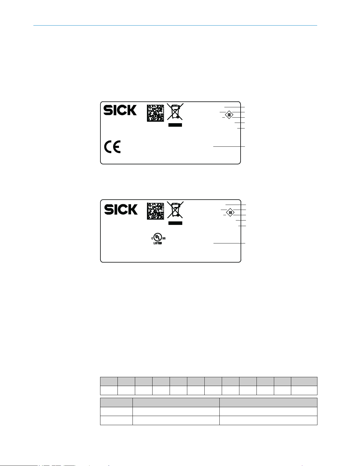
3.1.1 Type label
The type label gives information for identification of the device.
The type labels are located on the underside of the device.
Figure 1: Structure of the type label
The UL certification is dependent on the type. An existing UL certification can be found
on the type label.
PRODUCT DESCRIPTION 3
3.1.2 Type code
8024536//2019-08-30 | SICK O PE R AT I NG IN S TR U CT I ON S | RFU61x
Subject to change without notice
Figure 2: Structure of the type label with UL symbol
Type designation
1
Part number
2
Serial number
3
Supply voltage and power consumption
4
MAC address (placeholder)
5
Approval-related details (region-specific)
6
The devices of the RFU6xx product family are arranged according to the following type
code:
RFUxyz-abcde
R F U x y z - a b c d e
1 2 3 4 5 6 7 8 9 10 11
Position Description Characteristic
1 ... 2 RF (Radio Frequency Identification) –
3 Frequency band U: Ultra High Frequency
13
Page 14
3 PRODUCT DESCRIPTION
Position Description Characteristic
4 ... 5 Product family or version (working
6 Device type 0: Base type (EPCglobal UHF Class 1 Gen‐
7 Internal antenna 0: No integrated antenna
8 Connections for external antennas 0: No connection
9 Electrical connections 1: 1 x male connector, M12, 17-pin, A-
10 ... 11 Country-specific radio equipment
range)
approval
61: ≤0.5 m (Short Range)
62: ≤2 m (Mid Range)
63: ≤10 m (Long Range)
65: ≤10 m (Long Range)
eration 2, ISO/IEC 18000-6C)
1: With integrated antenna, circularly
polarized
3: 3 connections
4: 4 connections
coded; 1 x female connector, M12, 4-pin,
D-coded
4: Cable 0.9 m with male connector, DSub-HD, 15-pin
5: 1 x female connector, M12, 8-pin, Xcoded
6: 1 x male connector, M12, 4-pin, Acoded, 1 female connector, M8, 4-pin,
coded, 1 x female connector, M12, 8-pin,
X-coded
00: Europe ...
Type-dependent, see type-specific online
data sheet at:
www.sick.com/RFU61x
•
NOTE
Not all combinations are possible according to the type code. The available device vari‐
ants can be found online at:
www.sick.com/RFU61x
•
14
O PE R AT I NG IN S TR U CT I ON S | RFU61x 8024536//2019-08-30 | SICK
Subject to change without notice
Page 15
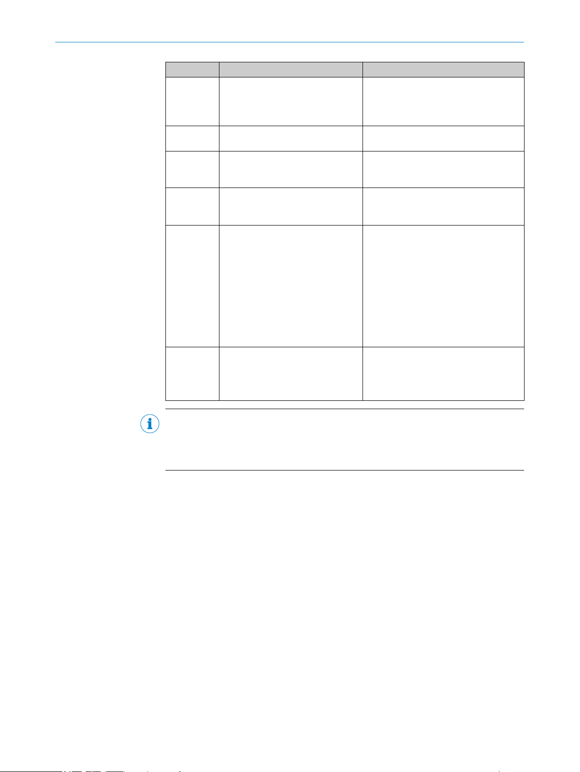
3.2 Product characteristics
92 (
3.62
)
1
9
8
94 (
3.70
)
106.4 (
4.19
)
ReadyRFLink/Act
microSD
40 (
1.57
)
16
(
0.63
)
36 (
1.42
)
â
80 (
3.15
) 38 (
1.50
)
12
(
0.47
)
71 (
2.80
)
40 (
1.57
)
5
(
0.20
)
6.4
(
0.25
)
17.5
(
0.69
)
78.8 (
3.10
)
1 3 2
91°
3 (
0.12
)
11.5 (
0.45
)
9.5 (
0.37
)
2
1
4
3
2 3
4 5
ß
á à
6
7
17.5
(
0.69
)
3.2.1 Device view
PRODUCT DESCRIPTION 3
Figure 3: RFU61x-106xx: Structure and dimensions, unit: mm (inch), decimal separator: period
Connection 1: Power (male connector, M12, 4-pin, A-coded)
1
Connection 3: Trigger (female connector, M8, 4-pin, coded)
2
Connection 2: PoE (female connector, M12, 8-pin, X-coded)
3
Slot for microSD memory card
4
“USB” connection (female connector, 5-pin, Micro B type). The USB interface must only be
5
used temporarily as a servicing interface!
Side type label
6
Optics cover with integrated antenna
7
4 x multi-colored LED (status)
8
4 x multi-color LED (process feedback)
9
2 x M5 threaded mounting holes, 6 mm deep, for attaching the mounting straps
ß
2 x M5 blind tapped holes, 7 mm deep, for alternative mounting of the device
à
type label with integrated pressure compensation membrane
á
2 x screw (M2,5 socket screw), captive, for side cover
â
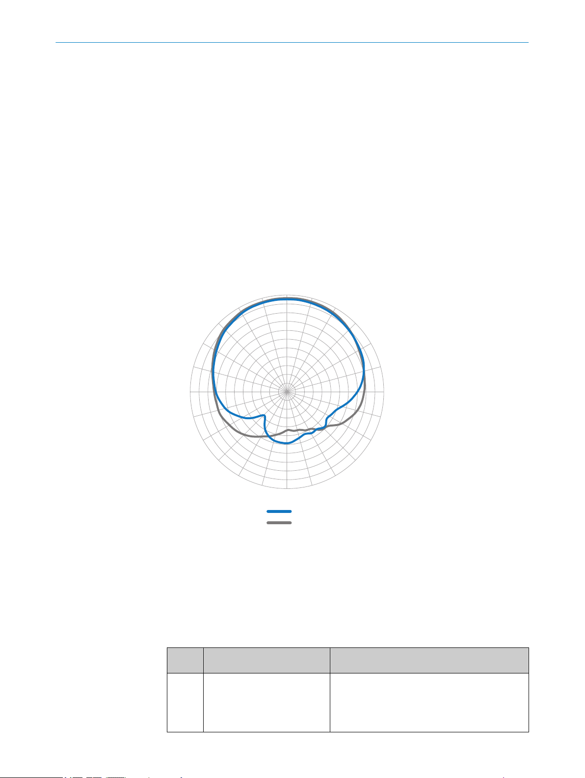
3.2.2 Working range of the antenna
8024536//2019-08-30 | SICK O PE R AT I NG IN S TR U CT I ON S | RFU61x
Subject to change without notice
Sensing range of the reading and writing field
The environment influences the UHF field of the integrated antenna, making it impossi‐
ble to provide a “clear” demarcation of the sensing range.
15
Page 16
–33
–30
–27
–24
–21
–18
–15
–12
–9
–6
–3
0°
15°
30°
45°
60°
75°
90°
105°
120°
135°
150°
165°
180°
–165°
–150°
–135°
–120°
–105°
–90°
–75°
–60°
–45°
–30°
–15°
2
1
0
3 PRODUCT DESCRIPTION
•
•
In addition to the read results, the RFU device can also output diagnostic data that pro‐
vide an indication of the write and read quality. This data can be used to achieve opti‐
mum read results when setting up the system.
The radiation pattern shown here for the device’s antenna was obtained in a repro‐
ducible environment (absorber chamber as a reflection-free space) for illustrative pur‐
poses. The diagram may therefore only have limited applicability to your specific appli‐
cation. The diagram shows how the UHF field propagates in a reflection-free space, but
cannot be used on-site to draw any conclusions on the likely sensing range in a real
application.
Application-specific reflections can result in both overreaches and “holes”
(destructive interferences).
Other factors that can significantly impact the sensing range include:
Quality of the transponder. The quality depends on the antenna gain, the inte‐
°
grated transponder IC and its sensitivity, the reflected energy.
Material of the carrier object (plastic, wood, metal)
°
Objects between the device and transponder that can affect the UHF field
°
(items, liquids, people)
3.2.3 Scope of delivery
16
O PE R AT I NG IN S TR U CT I ON S | RFU61x 8024536//2019-08-30 | SICK
Figure 4: Radiation pattern of the integrated antenna of the RFU61x (typical): Measured antenna
gain in dBic at 866.5 MHz, LHCP (left-hand circularly polarized)
Horizontal plane (azimuth)
1
Vertical plane (elevation)
2
The delivery of the device includes the following components:
Table 2: RFU61x: scope of delivery
No. of
units
1 Device in the version ordered
Component Notes
RFU61x-106xx
(region assignment)
The M12 and M8 electrical connections sealed with
tightly-fastened protective plugs or caps.
The joint side cover for the USB interface and the
memory card slot is closed and screwed tight.
Subject to change without notice
Page 17
PRODUCT DESCRIPTION 3
No. of
units
1 Mounting kit, consisting of
Component Notes
Fastening clamps, protruding after mounting for fas‐
2 x mounting strap
•
2 x countersunk head screw
•
with hexagon socket, M5 x 8
Printed Quick Start Guide, num‐
ber of language versions depen‐
dent on region.
tening the device from the front at both sides. Alter‐
natively for mounting from the rear: 2 M5 threaded
mounting holes on the rear of the device.
All available language versions of the Quick Start
Guide can also be found online as PDFs at:
www.sick.com/RFU61x
•
The following associated components are not included in the delivery. The components
are available on the Internet.
Table 3: RFU61x: Other components
Component Notes
SOPAS ET configuration software and
device description file (*.sdd-file) for the
RFU61x
RFU61x operating instructions as PDF in
English, French and German. Other lan‐
guages are available online where applic‐
able.
RFU parameter description as PDF in Eng‐
lish and German.
Available online at:
www.sick.com/SOPAS_ET
•
Available online at:
www.sick.com/RFU61x
•
Accessories
The following accessories for constructing a complete RFID read/write station are not
included in the scope of delivery of the device. If required, order accessories separately.
Read cycle trigger sensor, e.g. photoelectric retro-reflective sensor for object-spe‐
•
cific triggering
Suitable number of transponders depending on the application
•
3.2.4 Product features and functions (overview)
NOTE
In addition to the existing operating instructions, the use of the RFU parameter descrip‐
tion is recommended:
This parameter description explains the UHF-RFID-specific parameters of all
•
device variants of the RFU6xx product family up to and including the “Service”
user level.
The parameter description supports the user in configuring applications with the
•
SOPAS ET configuration software.
The parameter description is available in English (part no. 8023085) and German (part
no. 8023084) as well as other languages if required.
The RFU parameter description can be found on the online product page at:
www.sick.com/RFU61x
•
8024536//2019-08-30 | SICK O PE R AT I NG IN S TR U CT I ON S | RFU61x
Subject to change without notice
17
Page 18

3 PRODUCT DESCRIPTION
Table 4: Overview of product features and functions of the device
Product feature/func‐
tion
Security and ease of
use
Convenient operation/
configuration
Reading Operation
Mode
Read cycle
Radio interface(s)
Transponder Process‐
ing
Transponder Manage‐
ment
Data processing
Characteristic
Rugged, compact metal housing, CE marking (Europe)
•
Automatic self-test at system start
•
Diagnostic tools for device setup and (remote) device monitoring
•
Configurable output of the read results including read diagnostics
•
data in two output formats
Operating data request. In the event of an error: output of codified
•
error messages on request
Test string function (heartbeat) can be activated to signal that the
•
device is ready for operation
Future-proof due to firmware update via data interface
•
Future-proof SOPAS ET configuration software with password-pro‐
•
tected configuration mode
SICK AppSpace ready: The device already includes SensorApp for
•
integrating it into existing communication networks
Low power consumption
•
Wide supply voltage range. Supply via separate power source or
•
PoE.
Large ambient temperature range. For details, see "Technical data",
•
page 61
Parameter cloning (to back up the configuration data in the internal
•
device memory):
By pluggable microSD memory card 1) externally in the device
°
Configuration (online or offline) using SOPAS ET configuration soft‐
•
ware
Single Tag ID Wizard (assistant) to help with initial configuration
•
Configuration and starting of device functions via a web server
•
(SOPASair) or command strings
Optional function blocks for easier integration into PLC programs
•
PROFINET single port : Configuration via GSD parameterization
•
Application-specific programming is possible using the SICK AppStu‐
•
dio development environment.
You can find further information on the Internet at: www.sick.com/
SICK_AppStudio
Status and process feedback indicators via LEDs
•
Start/stop operation: For reading one or more transponders during
•
a read cycle.
Start and stop conditions of the read cycle can be configured in the
•
object trigger control: digital input
Integrated antenna
•
Base model RFU610 supports all standard passive transponders
•
that are compatible with EPCglobal UHF Class 1 Generation 2 or
ISO/IEC-18000-6C
Reading, writing, and multiple overwriting of the data on the
•
transponders, depending on the application
Within a process chain, the device supplying the data is a partial
•
component for the complete visualization of data
Decoding of the UII in HEX, BIN and ASCII. Supports GS1 TDS and
•
other industry-specific standards such as VDA55xx.
Variable read data output based on event-dependent evaluation
•
conditions
Influencing the output string by filtering and output sorting
•
Implementation of application-specific data output protocols using
•
the SICK AppStudio development environment (flexible back-end
integration)
18
O PE R AT I NG IN S TR U CT I ON S | RFU61x 8024536//2019-08-30 | SICK
Subject to change without notice
Page 19
PRODUCT DESCRIPTION 3
Product feature/func‐
tion
Data communication Host interface
Electrical Interfaces
Connectivity (Design)
1)
Optional accessories.
2)
USB interface must only be used temporarily as a servicing interface!
Characteristic
Two data output formats configurable.
•
The output is switchable to different physical or logical interfaces.
•
Parallel operation is possible. For outputting the data to a furtherprocessing computer.
Aux interface
Fixed data output format.
•
The output is switchable to different physical or logical interfaces.
•
For the device configuration and diagnostics as well as the
transponder access.
Host interface
•
Ethernet (supported protocols include, amongst others,
°
PROFINET single port).
Aux interface
•
Ethernet, USB
°
1 digital input for external trigger sensor
•
Voltage supply (power or PoE)
•
RFU61x-106xx: 2 x M12 male circular connector, 1 x M8 male circu‐
•
lar connector, 1 x USB (Micro B type)
2)
3.2.5 Memory card
NOTE
The memory card is an optional accessory and is not included in the scope of delivery.
Functions
The device can execute the following functions on the plug-in microSD memory card:
Saving the parameter set (cloning function)
•
Semi-automatic, additional storage of the internal parameter set (device configura‐
tion data) on an external memory medium. This takes place in the framework of
the recommended backup concept for the 4Dpro device parameter sets.
This function is initiated by using the “permanent” option to save the internal
°
parameter set, e.g. via the SOPAS ET configuration software.
The function is used, among other things, to conveniently transfer the para‐
°
meter set to an replacement device of the same type in the event of an fault.
A MicroSD memory card that can be plugged into the device serves as an
°
optional, external medium
Recording of diagnostic read data
•
Continuous recording of diagnostic read data after the first manual start, e.g., via
SOPAS ET. Recording is resumed after a device restart if the function has been
permanently set.
Other functions on request.
•
We recommend using an empty memory card when storing a parameter set for the first
time (if necessary, use a PC and card reader to check and delete the contents of the
card).
8024536//2019-08-30 | SICK O PE R AT I NG IN S TR U CT I ON S | RFU61x
Subject to change without notice
19
Page 20
1
2 3
PRODUCT DESCRIPTION
3
NOTE
Only use types approved by SICK to ensure reliable function of the memory card. You
can find these as accessories online at:
www.sick.com/RFU61x
•
The memory card has no write protection that can be activated.
Indication of operational readiness
The “microSD” optical indicator shows the status of the memory card after installation
in the device. It lights up in different colors according to the status, see "Optical status
indicators on the display panel", page 51.
NOTICE
Possible data loss!
When the indicator is green (operational), this does not mean that the device is actually
accessing the memory card for reading or writing.
Do not remove the memory card or switch off the supply voltage while the follow‐
b
ing functions are taking place in the device via the SOPAS ET configuration soft‐
ware:
■
Saving the parameter values using the “permanent” option
■
Starting functions that access the memory card (e.g. concurrent logging of
data)
Inserting the memory card in the device:
NOTICE
Risk of damage to the memory card!
To safely install the memory card, make sure there is no power to the device
b
before you insert it.
Ensure the IP67 enclosure rating of the device is maintained see "Conditions for speci‐
fied enclosure rating", page 10.
The card slot on the device is located under the cover foil on the side opposite the elec‐
trical connections.
Figure 5: Slot for MicroSD memory card and “USB” connection
2 x screw, M2.5 hexagon socket
1
Slot for microSD memory card
2
“USB” connection (female connector, 5-pin, Micro B type)
3
1. Switch off the supply voltage to the device.
2. Loosen both screws on the cover.
3. Carefully fold up the cover.
4. Making sure it is in the correct position, insert the memory card into the slot until
it locks into place. When doing so, orient the contacts so that they are facing
towards the device and downwards as per the symbol on the device.
20
O PE R AT I NG IN S TR U CT I ON S | RFU61x 8024536//2019-08-30 | SICK
Subject to change without notice
Page 21
PRODUCT DESCRIPTION 3
5. Screw the cover back on. Recommended tightening torque for the cover screws:
30 Ncm ± 5 Ncm.
6. Switch on the supply voltage for the device.
Interpretation of the stored parameter set
Once it is switched on, the device automatically detects the presence of a memory card
and, depending on the card’s content, behaves as follows:
■
If the memory card is empty or if does not contain a parameter set that can be
interpreted by the device: the device saves its currently valid internal parameter
set to the card (provided there is sufficient storage space) and starts with the
internal parameter set.
■
If the card contains a parameter set that can be interpreted by the device: the
device overwrites the currently valid internal parameter set with this external para‐
meter set.
The goal is for the internal parameter set and the parameter set saved externally to
always be identical.
Removing the memory card from the device:
NOTICE
Risk of damage to the memory card!
To safely remove the memory card while the device is in operation:
b
In SOPAS ET, execute the Remove SD card command under Analysis/SD card and
°
wait for SOPAS ET to provide confirmation.
If this command is not accessible, the memory card can also be removed
°
when there is no power to the device.
8024536//2019-08-30 | SICK O PE R AT I NG IN S TR U CT I ON S | RFU61x
Subject to change without notice
21
Page 22

4 TRANSPORT AND STORAGE
4 Transport and storage
4.1 Transport
For your own safety, please read and observe the following notes:
NOTICE
Damage to the product due to improper transport.
■
The device must be packaged for transport with protection against shock and
damp.
■
Recommendation: Use the original packaging as it provides the best protection.
■
Transport should be performed by trained specialist staff only.
■
The utmost care and attention is required at all times during unloading and trans‐
portation on company premises.
■
Note the symbols on the packaging.
■
Do not remove packaging until immediately before you start mounting.
4.2
Unpacking
■
Before unpacking, it may be necessary to equalize the temperature to protect the
device from condensation.
■
Handle the device with care and protect it from mechanical damage.
■
Remove the protective caps or protective plugs on the electrical connections
immediately before connecting the connecting cable to prevent dirt and moisture
from entering.
4.3 Transport inspection
Immediately upon receipt in Goods-in, check the delivery for completeness and for any
damage that may have occurred in transit. In the case of transit damage that is visible
externally, proceed as follows:
■
Do not accept the delivery or only do so conditionally.
■
Note the scope of damage on the transport documents or on the transport com‐
pany's delivery note.
■
File a complaint.
NOTE
Complaints regarding defects should be filed as soon as these are detected. Damage
claims are only valid before the applicable complaint deadlines.
4.4 Storage
22
O PE R AT I NG IN S TR U CT I ON S | RFU61x 8024536//2019-08-30 | SICK
Store the device under the following conditions:
■
Recommendation: Use the original packaging.
■
Electrical connections are provided with protective caps and plugs (as they are on
delivery).
■
Do not store outdoors.
■
Store in a dry area that is protected from dust.
■
So that any residual damp can evaporate, do not package in airtight containers.
■
Do not expose to any aggressive substances.
■
Protect from sunlight.
■
Avoid mechanical shocks.
■
Storage temperature: see "Technical data", page 61.
Subject to change without notice
Page 23

TRANSPORT AND STORAGE 4
■
Relative humidity: see "Technical data", page 61.
■
For storage periods of longer than 3 months, check the general condition of all
components and packaging on a regular basis.
8024536//2019-08-30 | SICK O PE R AT I NG IN S TR U CT I ON S | RFU61x
Subject to change without notice
23
Page 24

MOUNTING
5
5 Mounting
5.1 Overview of mounting procedure
The procedure for mounting the device is divided into the following steps:
1. Select a suitable mounting location for the device.
The mounting location and position depend on the following factors:
Identification task
°
Working range of the device (see "Working range of the antenna", page 15)
°
Transponder used
°
Environmental influences
°
2. Mount the device at the intended reading point and temporarily align the device to
the object with transponder. Make sure that there is a suitable distance to the
object.
3. If required, mount the read-cycle sensor for object-specific triggering.
After the electrical installation is complete and while adjusting the device parameters to
suit the application:
4. Finely align the device to the object and adjust it.
5. Test for successful reading and writing of the device in operational use of the
application.
5.2 Preparation for mounting
5.2.1 Installation requirements
Space requirements
■
For the typical space requirements, see the:
Dimensional drawing of the device see "Device view", page 15 and propaga‐
°
tion of the UHF field, see "Working range of the antenna", page 15.
The device does not require any physical or visual contact with the transponders. The
device does, however, need to be aligned with the reading space.
Environmental influences
■
Comply with technical data, such as the permitted ambient conditions for opera‐
tion (e.g. approved region, ambient temperature range, ground potential), see
"Technical data", page 61.
■
To prevent condensation, avoid exposing the device to rapid changes in tempera‐
ture.
■
To prevent additional external heating of the device, protect the device against
sunlight.
■
In order to avoid reflections of the UHF waves and any associated physical phe‐
nomena, make sure if possible that there are no metal surfaces on the side of the
device in the direction of the transponder.
Possible disturbances of the UHF field caused by reflections of the UHF waves are:
Overreaches
°
“Holes” (destructive interferences)
°
■
To avoid attenuation of the UHF field by absorption, exclude the following between
device and transponder:
Electrically conductive material, e.g. liquids (water)
°
Persons or animals
°
Mounting
24
O PE R AT I NG IN S TR U CT I ON S | RFU61x 8024536//2019-08-30 | SICK
Subject to change without notice
Page 25

MOUNTING
■
Fasten the device using the 2 fastening clamps supplied or the 2 M5 threaded
mounting holes.
■
Mount the device where they will not be exposed to shocks or vibration.
5.2.2 Instructions for mounting the device when the ambient temperature can fall below 0 °C
The device can also be operated at low ambient temperatures. For details, see "Techni‐
cal data", page 61.
NOTE
For the electrical installation procedure, see "Instructions for electrical installation when
the ambient temperature can fall below 0 °C", page 40
NOTICE
Operating the device at the lower limit of the permissible ambient temperature range
The ensure the device can produce the required heating power, do not expose the
device to strong air flows (e.g. from a ventilation system).
If necessary, take appropriate measures to shield the device from air flows.
b
NOTICE
If the ambient temperature is below 0 °C, please note:
5
Do not move the connecting cables to the device
•
5.2.3 Auxiliary equipment required
■
If the two fastening clamps of the enclosed mounting kit do not cover the mount‐
ing situation of the application, the customer must provide a suitable mounting
device (bracket). The bracket requires sufficient load-bearing capacity, see "Tech‐
nical data", page 61 and dimensions adapted to the device, see "Device view",
page 15.
■
2 M5 screws to attach the device to a bracket if the supplied mounting straps are
not used.
NOTE
The screws are for mounting the device on mounting equipment (bracket) supplied
by the user. The screw length required depends on the mounting base (wall thick‐
ness of the bracket).
When using an optional SICK bracket, the screws for mounting the device on the
bracket are included in the scope of delivery.
NOTICE
Risk of damage to the device!
Screws that are not suitable for the length of the threaded mounting holes can
damage the device.
M5 threaded mounting hole for mounting from the rear: screw in screws to a
•
maximum depth of 7 mm!
M5 threaded mounting holes for mounting strap: Do not exceed the maxi‐
•
mum screw-in depth of 6 mm!
■
Tool and tape measure
8024536//2019-08-30 | SICK O PE R AT I NG IN S TR U CT I ON S | RFU61x
Subject to change without notice
25
Page 26

5 MOUNTING
5.2.4 Mounting device
The device can be mounted using the 2 mounting straps (supplied mounting kit part no.
2105772) after attachment on the device from the front or rear. The associated 2 M5
threaded mounting holes for the fastening clamps are each located on the outside of
the rear of the device, in the recess, see "Device view", page 15.
Figure 6: Back view RFU61x: device with mounted mounting straps
Alternatively, the device is fastened using the 2 M5 internal threaded mounting holes.
The threaded mounting holes are also located on the rear of the device.
Further, optional SICK brackets
The device can be mounted using additional optional SICK brackets, a combination of
SICK brackets and elements, or a customer-specific bracket.
SICK offers prefabricated brackets which are optimally suited for mounting the device
in a wide range of applications.
Also see on Internet at:
www.sick.com/RFU61x
•
NOTE
Dimensional drawings for SICK brackets and, if applicable, mounting instructions can
be found online at: www.sick.com
To do so, enter the 7-digit part number of the bracket in the search field.
b
User-supplied brackets
A user-supplied bracket should meet the following requirements:
■
Stable mounting device
– Allow the device to be aligned in the x and y axes.
– The mounting device must be able to bear the weight of the device, including
connecting cables, in a shock-proof manner, see "Technical data", page 61.
– In mounting situations with strong vibrations, it may be necessary to provide
shock mounts.
■
For mounting the device according to the dimensional drawing: 2 suitable holes for
M5 screws.
5.3
26
Mounting location
When selecting the mounting location, the following factors are significant:
O PE R AT I NG IN S TR U CT I ON S | RFU61x 8024536//2019-08-30 | SICK
Subject to change without notice
Page 27

Spatial working range of the antenna
•
Distance to objects with a transponder
•
Influence of the environment on the UHF field produced, for example:
•
°
°
°
5.4 Mounting the device
WARNING
Risk of injury due to damage to the device
For reasons of safety, if a device shows visible signs of damage do not put it into opera‐
tion, or take it out of operation immediately.
Damage includes, for example, depending on type:
Housing: cracking, splitting or fracture
•
Electrical connections: cracks or detachment from the housing
•
Device with cable connection: damage to the cable outlet or cable itself
•
NOTICE
Risk of damaging the device!
Observe the maximum screw-in depth of the blind tapped holes on the device. Longer
screws than the specified screw-in depth damage the device.
MOUNTING
Metal surfaces located to the side of and in the vicinity of the device
Electrically conductive liquids between the antenna and transponder
Persons between the antenna and transponder
5
Use screws of suitable length.
b
Basic arrangement of the device to the transponders
UHF transponders have dipole antennas and therefore preferential directions within the
radiation field of the antenna. The transmitting and receiving performance will be
higher or lower depending on the orientation of the dipole antenna of the transponder
to the axis perpendicular to the antenna surface. The reading and writing rate and sens‐
ing range can therefore be subject to fluctuations.
NOTE
If the dipole antenna of the transponder is oriented lengthwise along the axis perpen‐
dicular to the antenna surface, no reading or writing of the transponder will be possible.
Figure 7: The optimal orientation of the transponder for good writing and reading results is
demonstrated here for an external UHF antenna
8024536//2019-08-30 | SICK O PE R AT I NG IN S TR U CT I ON S | RFU61x
Subject to change without notice
27
Page 28

10°
1
5 MOUNTING
Mounting and aligning the device
NOTICE
Avoid mutual interference when operating several devices
When the reading/writing ranges of several independently operated devices overlap,
this can lead to mutual impairment of the system performance of the devices.
In order to avoid such constellations, the devices each offer Sync mode.
With the Sync Mode, several devices can be synchronized in read/write behavior. For
this purpose, the devices must be connected to one another via an Ethernet network.
Sync mode then ensures that only one device at a time is performing a read/write oper‐
ation and therefore communicating over the air interface. One master controls up to
three slaves.
1. Prepare the base for mounting the bracket of the device, see "Preparation for
mounting", page 24.
Recommendation: Depending on the application it may be possible to use one of
the optional SICK brackets. If necessary, perhaps also in combination with other
SICK brackets.
2. At the intended reading location, place an object with transponder within the work‐
ing range of the device (static object only).
3. Mount the device bracket onto the base.
4. Tighten screws through the bracket into the blind tapped holes of the device and
slightly tighten.
5. Orient the front side of the device towards the object.
Ensure, where possible, that there are no large metal surfaces located in
°
front of the device.
If this is unavoidable, do not mount the device in the same plane as the sur‐
°
face but rather at an angle of inclination of approx. 10°.
Figure 8: Selected angle of inclination of the device or external antennas when there
is a large metal surface in front, e. g. 10°
Metal surface
1
6. Tighten the screws.
✓
The device is approximately aligned with the object to be detected.
7. Check the general suitability of the alignment for objects of different sizes and
varying positions of the transponder in operational use of the application.
5.5
Mounting external components
5.5.1 Mounting the external read cycle trigger sensor
Conveying line
To detect objects with transponders, mount the trigger sensor in suitable proximity to
the device in front of the device in the opposite direction to the direction of movement.
28
O PE R AT I NG IN S TR U CT I ON S | RFU61x 8024536//2019-08-30 | SICK
Subject to change without notice
Page 29

MOUNTING 5
NOTE
A large selection of photoelectric sensors and accessories (brackets, connecting
cables) can be found online at: www.sick.com
8024536//2019-08-30 | SICK O PE R AT I NG IN S TR U CT I ON S | RFU61x
Subject to change without notice
29
Page 30

6 ELECTRICAL INSTALLATION
6 Electrical installation
6.1 Safety
6.1.1 Notes on electrical installation
Connection work
Electrical installation must only be performed by electrically qualified personnel.
•
Standard safety requirements must be observed when working on electrical sys‐
•
tems!
All connection work must be performed at ambient temperatures above 0 °C, see
•
"Ambient data", page 63
Electrical connections between the device and other devices may only be made or
•
separated in a voltage-free state. Otherwise, there is a risk of damaging the
devices.
Where connecting cables with one end open are concerned, make sure that bare
•
wire ends are not touching (risk of short circuit when the supply voltage is switched
on). Wires must be appropriately insulated from each other. This also applies to
unused wires.
The wire cross-sections of the data and, if applicable, switching signal cables must
•
be selected in accordance with the applicable national standards.
NOTE
For additional instructions on operating the device at ambient temperatures below
0 °C, see "Prerequisites", page 40
Supply voltage
Connect the device only to the permissible supply voltage, see "Connecting the
•
supply voltage", page 43
The wire cross-sections in the supply cable from the user’s power system must be
•
selected in accordance with the applicable national standards. When this is being
done in Germany, observe the following standards: DIN VDE 0100 (Part 430) and
DIN VDE 0298 (Part 4) and/or DIN VDE 0891 (Part 1).
All circuits connected to the device must be designed as ES1 circuits. The voltage
•
supply or power supply unit must satisfy ES1 requirements in accordance with the
currently applicable EN 62368-1, see "Mechanics and electronics", page 62.
Only switch on the supply voltage to the device , after first:
•
Completing the connection work
°
Carefully checking the wiring work
°
30
O PE R AT I NG IN S TR U CT I ON S | RFU61x 8024536//2019-08-30 | SICK
Subject to change without notice
Page 31

ELECTRICAL INSTALLATION 6
Data cables
NOTE
Layout of data cables
Use shielded data cables with twisted-pair wires.
•
The possible cable length between the device and host computer depends on:
•
The chosen physical version of the host interface
°
The data transmission rate set in the device
°
For further information, see "Wiring the data interface", page 46.
Implement the shielding design correctly and completely.
•
To avoid interference, always use EMC-compliant cables and layouts. This applies,
•
for example, to cables for switched-mode power supplies, motors, clocked drives,
and contactors.
Do not lay cables in parallel with voltage supply cables or motor cables in cable
•
channels over longer distances.
Conditions for specified enclosure rating
To ensure compliance with the specified IP67 enclosure rating of the device, the follow‐
ing requirements must be met. If these requirements are not met, the device does not
fulfill any specified enclosure rating.
The joint side cover for the USB interface and the memory card slot is placed
•
against the device and screwed on tight.
The cables plugged into the electrical M12 and M8 connections must be screwed
•
tight.
Any M12 and M8 connections that are not being used must be sealed with protec‐
•
tive plugs or caps, depending on type. These plugs or caps must be screwed tight
(as in the delivery condition).
The same also applies to the EMC requirement (ESD) according to CE.
NOTICE
The type label on the lower side of the device contains a pressure equalizing mem‐
brane. If damaged, water and dust leaks could occur.
Positions of the individual elements see "Device view", page 15
NOTICE
The device can, if necessary, be operated for a short time without the side cover to per‐
form the following tasks:
Inserting or removing the optional memory card
•
Temporary use of the USB interface as a servicing interface
•
During this time, protect the device against moisture and dust.
8024536//2019-08-30 | SICK O PE R AT I NG IN S TR U CT I ON S | RFU61x
Subject to change without notice
31
Page 32

SICK
Device
7 46
Power Supply
U
= 8
= 9
1 2 3
I
5
System
Controller
6 ELECTRICAL INSTALLATION
6.1.2 Prerequisites for safe operation of the device
WARNING
Risk of injury and damage caused by electrical current!
As a result of equipotential bonding currents between the device and other grounded
devices in the system, faulty grounding of the device can give rise to the following dan‐
gers and faults:
■
Dangerous voltages are applied to the metal housings.
■
Devices will behave incorrectly or be destroyed.
■
Cable shielding will be damaged by overheating and cause cable fires.
Remedial measures
■
Only skilled electricians should be permitted to carry out work on the electrical sys‐
tem.
■
If the cable insulation is damaged, disconnect the voltage supply immediately and
have the damage repaired.
■
Ensure that the ground potential is the same at all grounding points.
■
Where local conditions do not meet the requirements for a safe earthing method,
take appropriate measures (e.g., ensuring low-impedance and current-carrying
equipotential bonding).
The device is connected to the peripheral devices (voltage supply, any local trigger sen‐
sor(s), system controller) via shielded cables. The cable shield – for the data cable,
for example – rests against the metal housing of the device. The device can be
grounded through the cable shield or through a blind tapped hole in the housing,
for example.
If the peripheral devices have metal housings and the cable shields are also in contact
with their housings, it is assumed that all devices involved in the installation have the
same ground potential.
This is achieved by complying with the following conditions:
■
Mounting the devices on conductive metal surfaces
■
Correctly grounding the devices and metal surfaces in the system
■
If necessary: low-impedance and current-carrying equipotential bonding between
areas with different ground potentials
32
O PE R AT I NG IN S TR U CT I ON S | RFU61x 8024536//2019-08-30 | SICK
Figure 9: Example: Occurrence of equipotential bonding currents in the system configuration
System controller
1
Device
2
Voltage supply
3
Grounding point 2
4
Closed current loop with equalizing currents via cable shield
5
Ground potential difference
6
Subject to change without notice
Page 33

Electro-
optical
signal
isolator
Electro-
optical
signal
isolator
Power
Supply
SICK
Device
1 2 2 43
6 5
System
Controller
= 7
= 8
= 9
6
Grounding point 1
7
Metal housing
8
Shielded electrical cable
9
ELECTRICAL INSTALLATION
If these conditions are not fulfilled, equipotential bonding currents can flow along the
cable shielding between the devices due to differing ground potentials and cause the
hazards specified. This is, for example, possible in cases where there are devices within
a widely distributed system covering several buildings.
Remedial measures
The most common solution to prevent equipotential bonding currents on cable shields
is to ensure low-impedance and current-carrying equipotential bonding. If this equipo‐
tential bonding is not possible, the following solution approaches serve as a suggestion.
NOTICE
We expressly advise against opening up the cable shields. This would mean that the
EMC limit values can no longer be complied with and that the safe operation of the
device data interfaces can no longer be guaranteed.
Measures for widely distributed system installations
On widely distributed system installations with correspondingly large potential differ‐
ences, the setting up of local islands and connecting them using commercially available
electro-optical signal isolators is recommended. This measure achieves a high degree
of resistance to electromagnetic interference.
Figure 10: Example: Prevention of equipotential bonding currents in the system configuration by
the use of electro-optical signal isolators
System controller
1
Electro-optical signal isolator
2
Device
3
Voltage supply
4
Grounding point 2
5
Grounding point 1
6
Metal housing
7
Shielded electrical cable
8
Optical fiber
9
The use of electro-optical signal isolators between the islands isolates the ground loop.
Within the islands, a stable equipotential bonding prevents equalizing currents on the
cable shields.
Measures for small system installations
8024536//2019-08-30 | SICK O PE R AT I NG IN S TR U CT I ON S | RFU61x
Subject to change without notice
33
Page 34

U
System
Controller
Power Supply
SICK
Device
8 6
5
21 3
4
7
= 9
= ß
6 ELECTRICAL INSTALLATION
For smaller installations with only slight potential differences, insulated mounting of the
device and peripheral devices may be an adequate solution.
Figure 11: Example: Prevention of equipotential bonding currents in the system configuration by
the insulated mounting of the device
System controller
1
Device
2
Voltage supply
3
Grounding point 3
4
Insulated mounting
5
Grounding point 2
6
Ground potential difference
7
Grounding point 1
8
Metal housing
9
Shielded electrical cable
ß
6.2 Wiring instructions
34
O PE R AT I NG IN S TR U CT I ON S | RFU61x 8024536//2019-08-30 | SICK
Even in the event of large differences in the ground potential, ground loops are effec‐
tively prevented. As a result, equalizing currents can no longer flow via the cable shields
and metal housing.
NOTICE
The voltage supply for the device and the connected peripheral devices must also guar‐
antee the required level of insulation.
Under certain circumstances, a tangible potential can develop between the insulated
metal housings and the local ground potential.
NOTICE
Faults due to incorrect wiring!
Incorrect wiring may result in operational faults.
Follow the wiring instructions closely.
•
Pre-assembled cables
Subject to change without notice
Page 35

NOTE
SOPAS ETSOPAS ET
PC
"Ethernet (Aux 1)"
USBUSB
RFU61x-
106xx
Cable 3
Cable 2
5
Power"
EthernetEthernet
"USB" (Aux 2), for temporary use only 4
Configuration
Reading result
display
Transponder
access
Reading
diagnostics
ReadyRFLink/Act
microSD
Cable 6
V
S
1
Pre-assembled cables can be found online at:
www.sick.com/RFU61x
•
Pre-assembled cables with open cable end at one end
NOTE
For information on the pin, signal and wire color assignments for the RFU61x see "Sig‐
nal assignment of cables with open cable end at one end", page 65, in the appendix.
6.3 Overview of all interfaces and connection options
NOTE
The USB interface of the device is used in industrial environments only as a service
interface for temporary use (e.g. for configuration, troubleshooting). Permanent use in
operational use of the system as a host interface is not intended.
NOTE
The numbering of the data interfaces (Aux 1, etc.) in the following block diagrams pro‐
vides a better overview, but is not shown in configuration tools such as the SOPAS ET
configuration software.
ELECTRICAL INSTALLATION 6
6.3.1 RFU61x-106xx (connection: power and Ethernet)
Service operation
The following functions can be executed via one of the three data interfaces (Aux 1, Aux
2 or Host 1):
Configuration
•
Representation of the reading result (detected transponders)
•
Transponder access (reading and writing data)
•
Reading diagnostics (read result in fixed output format)
•
For a detailed overview, see "Use of the data interfaces", page 38.
This is illustrated here for the Aux interface, the Aux port of the Ethernet interface, and
alternatively the USB interface.
Figure 12: Block diagram RFU61x-106xx (power and Ethernet connection): service operation, e.g.
display of read result
8024536//2019-08-30 | SICK O PE R AT I NG IN S TR U CT I ON S | RFU61x
Subject to change without notice
1
2
3
Supply voltage V
Power adapter cable for connection 1 (female connector, M12, 4-pin, A-coded/flying
leads), e.g. part no. 2095607
USB adapter cable (male connector, USB, Micro-B type/male connector, USB, type A)
S
35
Page 36

"Power"
ReadyRFLink/Act
microSD
Cable 4Cable 7
V
S
2
Trigger
sensor
1
PD
*)
"Ethernet (Host 1)"
HOST
Further data
processing
EthernetEthernet
RFU61x-106xx
Reading result 5
6
Cable 3
*) PD = Powered Devices 8
6 ELECTRICAL INSTALLATION
USB, alternative to Ethernet Aux port. The USB interface must only be used temporarily as
4
a servicing interface!
Configuration with SOPAS ET, prepared representation of the read result, transponder
5
access or reading diagnostics
Ethernet adapter cable for connection 2 (male connector, M12, 8-pin, X-coded/male con‐
6
nector, RJ-45, 8-pin), e.g. part no. 6049728
Read operation
In operational use of the application, the device outputs the read result to the further
processing computer via the host interface. Select one of two configurable output for‐
mats for this purpose. The device can also output the same output format or a second
output format in parallel via the Aux interface.
For a detailed overview, see "Use of the data interfaces", page 38.
Figure 13: Block diagram RFU61x-106xx (power and Ethernet connection): read operation
Trigger sensor for external read cycle, e.g. GL6 (part no. 1059241)
1
Supply voltage V
2
Power adapter cable for connection 1 (female connector, M12, 4-pin, A-coded/flying
3
S
leads), e.g. part no. 2095607
Ethernet adapter cable for connection 2 (male connector, M12, 8-pin, X-coded/male con‐
4
nector, RJ-45, 8-pin), e.g. part no. 6049728
Read result (configurable output format 1 or 2)
5
Data further processing
6
Trigger connecting cable for connection 3 (male connector, M8, 4-pin/male connector,
7
M8, 4-pin), e.g. part no. 2096347
PD = Energy consumer
8
6.3.2 RFU61x-106xx (connection: Power over Ethernet)
Service operation
The following functions can be executed via one of the three data interfaces (Aux 1, Aux
2 or Host 1):
Configuration
•
Representation of the reading result (detected transponders)
•
Transponder access (reading and writing data)
•
Reading diagnostics (read result in fixed output format)
•
For a detailed overview, see "Use of the data interfaces", page 38.
36
This is illustrated here for the Aux interface, the Aux port of the Ethernet interface, and
alternatively the USB interface.
O PE R AT I NG IN S TR U CT I ON S | RFU61x 8024536//2019-08-30 | SICK
Subject to change without notice
Page 37

SOPAS ETSOPAS ET
PC
"Ethernet (Aux 1)"
EthernetEthernet
USBUSB
PoE Switch
(Endspan)
...
DC 48 V/57 V
PSE
**)
PD
*)
RFU61x-
106xx
*) PD = Powered Devices 6 **) PSE = Power Sourcing Equipment 5
"Ethernet"
Cable 2
Cable 1
4
"Ethernet (Aux 1)/Power"
EthernetEthernet
"USB" (Aux 2), for temporary use only 3
Configuration
Reading result
display
Transponder
access
Reading
diagnostics
ReadyRFLink/Act
microSD
PoE Switch
(Endspan)
...
DC 48 V/57 V
PSE
**)
PD
*)
*) PD = Powered Devices 7 **) PSE = Power Sourcing Equipment 6
"Ethernet"
"Ethernet (Host 1)"
HOST
Further data
processing
EthernetEthernet
RFU61x-106xx
"Ethernet (Host 1)/Power"
Cable 3
Reading result 4
5
ReadyRFLink/Act
microSD
Cable 2
Trigger
sensor
1
EthernetEthernet
ELECTRICAL INSTALLATION 6
Figure 14: Block diagram RFU61x-106xx (PoE connection): service operation, e.g. display of read
result
Ethernet adapter cable (male connector, M12, 8-pin, X-coded/male connector, RJ-45, 8-
1
pin), e.g. part no. 6049728
USB adapter cable (male connector, USB, Micro-B type/male connector, USB, type A)
2
USB, alternative to Ethernet Aux port. The USB interface must only be used temporarily as
3
a servicing interface!
Configuration with SOPAS ET, prepared representation of the read result, transponder
4
access or reading diagnostics
PSE = Energy source
5
PD = Energy consumer
6
Read operation
In operational use of the application, the device outputs the read result to the further
processing computer via the host interface. Select one of two configurable output for‐
mats for this purpose. The device can also output the same output format or a second
output format in parallel via the Aux interface.
For a detailed overview, see "Use of the data interfaces", page 38.
Figure 15: Block diagram RFU61x-106xx (PoE connection): read mode
Trigger sensor for external read cycle, e.g. GL6 (part no. 1059241
1
Trigger connecting cable (male connector, M8, 4-pin, coded/male connector, M8, 4-pin,
2
coded), e.g. part no. 2096347
8024536//2019-08-30 | SICK O PE R AT I NG IN S TR U CT I ON S | RFU61x
Subject to change without notice
Ethernet adapter cable (male connector, M12, 8-pin, X-coded/male connector, RJ-45, 8-
3
pin), e.g. part no. 6049728
Read result (configurable output format 1 or 2)
4
Data further processing
5
PSE = Energy source
6
PD = Energy consumer
7
37
Page 38

RFU61x-106xx
PC:
SOPAS ET
configuration
software
4
HOST:
Further data
processing
5
PC/HOST
Aux 2
USB
◂ Configuration 1 ▸
Ethernet
Aux 1 ◂ Configuration, ... 2 ▸
Host 1 Data output 3 ▸
ELECTRICAL INSTALLATION
6
6.3.3 Use of the data interfaces
Figure 16: Data interfaces of the RFU61x-106xx and their preferred uses
Service operation: Configuration with SOPAS ET, interface only for temporary use
1
Service operation: Configuration with SOPAS ET, prepared representation of the read
2
result, transponder access or reading diagnostics
Read operation: Data output of the read result (configurable output format 1 or 2),
3
SOPAS ET configuration software
4
Data further processing
5
Table 5: Functions relating to data interfaces
Possible interface → Host 1 Aux 1 Aux 2
Assignable function
Ethernet Ethernet USB
1)
↓
Read result output (configurable format 1 or
O O
2)
Reading diagnostics (fixed output format)
With SOPAS ET: Configuration, representation
o o o
O
of the read results in the Quickstart display
window, transponder access
Configuration with commands
Configuration using web server
o o o
o o
2)
O = Output of the same function via the interfaces possible at the same time
o = Access only makes sense via one of the interfaces (risk of collision!)
1)
The USB interface must only be used temporarily as a servicing interface!
2)
Input using the terminal in SOPAS ET (Version 3.3.0 or higher) or other USB-capable terminal programs.
NOTE
Only one of several available functions can be assigned to each interface.
•
The logical Aux interface of the device can operate the Aux port of the Ethernet inter‐
face, and the USB interface in parallel.
38
O PE R AT I NG IN S TR U CT I ON S | RFU61x 8024536//2019-08-30 | SICK
The logical host interface of the device operates the host port of the Ethernet interface.
The data output triggered by means of a command string only occurs, however, at the
data interface on which the request was received.
Subject to change without notice
Page 39

6.4 Pin assignments of electrical connections
1
4 3
2
1
7
2
6
54
3
8
1
7
2
6
54
3
8
6.4.1 Connection: power and Ethernet
6.4.1.1 Connection 1: power
Figure 17: M12 male connector, 4-pin, A-coded
Table 6: Pin assignment of the “Power” connection
Pin Signal Function
1 V
2 N.c. –
3 GND_ext Primary ground
4 N.c. –
S
ELECTRICAL INSTALLATION 6
Supply voltage
6.4.1.2 Connection 2: “Ethernet”
Figure 18: Female connector, M12, 8-pin, X-coded
Table 7: Pin assignment of the “Ethernet” connection
Pin Signal Function
1 TD+ Sender+
2 TD– Sender–
3 RD+ Receiver+
4 RD– Receiver–
5 PoE– Supply voltage-
6 PoE– Supply voltage-
7 PoE+ Supply voltage+
8 PoE+ Supply voltage+
6.4.2 Connection: Power over Ethernet
6.4.2.1 Connection 2: “PoE”
Figure 19: Female connector, M12, 8-pin, X-coded
8024536//2019-08-30 | SICK O PE R AT I NG IN S TR U CT I ON S | RFU61x
Subject to change without notice
39
Page 40

4 1
3
2
6 ELECTRICAL INSTALLATION
Table 8: Pin assignment of the “PoE” connection
Pin Signal Function
1 TD+ Sender+
2 TD– Sender–
3 RD+ Receiver+
4 RD– Receiver–
5 PoE– Supply voltage-
6 PoE– Supply voltage-
7 PoE+ Supply voltage+
8 PoE+ Supply voltage+
6.4.3 Connection of external trigger sensor
6.4.3.1 Connection 3: “Trigger”
Figure 20: Female connector, M8, 4-pin, coded
Table 9: Pin assignment of the “Trigger” connection
Pin Signal Function
1 V
2 N.c. –
3 GND Functional ground
4 Sensor 1 Digital input
S trigger
Supply voltage for external trigger sensor
6.5 Instructions for electrical installation when the ambient temperature can fall below 0 °C
NOTE
For mounting instructions, see "Instructions for mounting the device when the ambient
temperature can fall below 0 °C", page 25
All device variants can also be operated at low ambient temperatures. For details, see
"Technical data", page 61
6.5.1 Prerequisites
Required supply voltage: see "Supply voltage", page 43
•
Use SICK standard cables for the specified ambient temperature range, see
•
www.sick.com/RFU61x
°
Do not operate the device at ambient temperatures below 0 °C when mounting or
•
connection work is being carried out.
Perform all connection work only in the ambient temperature range 0 °C to
•
+50 °C. Secure the connecting cables.
The joint side cover for the USB interface and the memory card slot is screwed
•
tightly onto the device.
40
O PE R AT I NG IN S TR U CT I ON S | RFU61x 8024536//2019-08-30 | SICK
Subject to change without notice
Page 41

All cables connected to the device must be clamped. Electrical M12 or M8 con‐
SOPAS ETSOPAS ET
PC
"Ethernet (Host 1/Aux 1)"
USBUSB
RFU61x-
106xx
Cable 3
5
"Power"
EthernetEthernet
"USB" (Aux 2), for temporary use only 4
Configuration
Reading result
display
Transponder
access
Reading
diagnostics
ReadyRFLink/Act
microSD
Cable 6
V
S
2
Trigger
sensor
1
•
nections that are not being used must be sealed with screw-on protective ele‐
ments as in the delivery condition. Protective caps for male connectors or protec‐
tive plugs for female connectors.
When operating the device at the lower limit of the permissible ambient tempera‐
•
ture range (see "Technical data", page 61), do not expose the device to strong air
flows (e.g. ventilation system, wind).
6.5.2 Behavior of the device when switched on
After application of the supply voltage and initialization, the device can immediately be
addressed by the SOPAS ET configuration software.
Table 10: Behavior of the device when switched on at low temperatures
Internal temperature of
housing
Below –25 °C “Ready” LED continuously flashes orange.
-25 °C ... -20 °C “Ready” LED continuously flashes green (warm-up phase).
From –20 °C “Ready” LED permanently lights up green.
1)
For Firmware Version V2.02
ELECTRICAL INSTALLATION 6
Behavior
Device is not operational because –25 °C is below the specified
minimum limit value.
Device is not operational (communication channel still disabled)
until the internal temperature has increased to –20 °C as a result
of the heat generated by the electronics. Duration approx. 2 min.
The device has started regular operation.
Once the supply voltage has been applied, the device uses integrated temperature sen‐
sors to measure its internal temperature. This is performed by the device while booting.
6.6 Installation steps
6.6.1 Wiring of the device for Quickstart
NOTE
The numbering of the data interfaces (Aux 1, etc.) in the following block diagrams pro‐
vides a better overview, but is not shown in the SOPAS ET configuration software.
Connection type: power and Ethernet
Figure 21: Commissioning: connection block diagram of the RFU61x-106xx (power and Ethernet)
8024536//2019-08-30 | SICK O PE R AT I NG IN S TR U CT I ON S | RFU61x
Subject to change without notice
Trigger sensor for external read cycle (optional)
1
Supply voltage V
2
Adapter cable (male connector, USB, Micro-B type/male connector, USB, type A)
3
S
41
Page 42

SOPAS ETSOPAS ET
PC
"Ethernet (Aux 1)"
USBUSB
PoE Switch
(Endspan)
...
DC 48 V/57 V
PSE
**)
PD
*)
RFU61x-
106xx
*) PD = Powered Devices 6 **) PSE = Power Sourcing Equipment 5
"Ethernet"
Cable 2
4
EthernetEthernet
"USB" (Aux 2), for temporary use only 3
Configuration
Reading result
display
Transponder
access
Reading
diagnostics
PD
*)
EthernetEthernet
"Ethernet (Host 1/Aux 1)/Power"
Cable 7
ReadyRFLink/Act
microSD
Trigger
sensor
1
6 ELECTRICAL INSTALLATION
USB, alternative to Ethernet Aux port. The USB interface must only be used temporarily as
4
a servicing interface!
Configuration with SOPAS ET, prepared representation of the read result, transponder
5
access or reading diagnostics
Adapter cable (male connector, M12, 8-pin, X-coded/male connector, RJ-45, 8-pin)
6
Procedure:
1.
Connect the communication interface (e.g. Ethernet) of the device directly 6to the
PC using a suitable cable.
2. Connect the “Power” connection (male connector, M12, 4-pin, A-coded) to the
power source using a suitable cable.
Connection type: Power over Ethernet
Figure 22: Initial commissioning: connection block diagram RFU61x-106xx (Power over Ethernet)
1
2
3
4
5
6
7
Procedure:
b
General for both connection types
1. If necessary, connect the trigger sensor for an external read cycle, such as a pho‐
42
O PE R AT I NG IN S TR U CT I ON S | RFU61x 8024536//2019-08-30 | SICK
Trigger sensor for external read cycle (optional)
Adapter cable (male connector, USB, Micro-B type/male connector, USB, type A)
USB, alternative to Ethernet Aux port. The USB interface must only be used temporarily as
a servicing interface!
Configuration with SOPAS ET, prepared representation of the read result, transponder
access or reading diagnostics
PSE = Energy source
PD = Energy consumer
Adapter cable (male connector, M12, 8-pin, X-coded/male connector, RJ-45, 8-pin)
Connect the PoE communication interface of the device to the PoE switch using a
suitable adapter cable 7.
toelectric sensor, to the “Trigger” connection.
The device offers the “Quickstart” operating mode for demonstrating its operating
principle. In this mode, the device automatically triggers a cyclic reading. The oper‐
ating mode can, for example, be started and terminated with the SOPAS ET config‐
uration software.
Subject to change without notice
Page 43

+
+
−
2
+
−
−
F
++
−
+
− −
V
S
1
F
+
+
−
+
−
−
V
S
1
2
+
RFU61x-106xx RFU61x-106xx
GND
GND_ext
GND
GND_ext
ELECTRICAL INSTALLATION 6
NOTICE
Quickstart mode is not intended to be used during normal operation. It requires
read cycle triggering to be configured in the object trigger control settings in
SOPAS ET.
2. Switch on the supply voltage for the device, see "Supply voltage", page 43.
✓
After successful initialization, the “Ready” LED illuminates green.
3. Turn on the PC and start Windows.
6.7
Connecting the supply voltage
6.7.1 Note on the supply voltage of the device
NOTICE
Risk of damage to the device due to reverse polarity of the supply voltage!
Reversing the polarity of the supply voltage may, under certain circumstances, damage
the device due to short circuit currents!
The supply voltage input for the RFID device is designed with internal circuit protection
to provide reverse polarity protection. For this purpose, there is a blocking diode in the
current path of the positive pole (see figure).
The negative pole of the supply voltage (primary ground, GND_ext) is electrically iso‐
lated from the functional ground (GND). The functional earth has a direct galvanic con‐
nection to the metal housing of the device for RF-related technical reasons.
Depending on the mounting location of the RFID device and the reference potential of
the supply voltage, a reversal of the polarity of the applied supply voltage can lead to
the following situation:
Figure 23: Reversal of the polarity of the supply voltage: no effect on the RFID device (see
requirements)
Fuse
1
Blocking diode
2
The housing of the RFID device is connected to functional earth.
6.7.2 Supply voltage
8024536//2019-08-30 | SICK O PE R AT I NG IN S TR U CT I ON S | RFU61x
Subject to change without notice
If the polarity of the supply voltage is reversed, the blocking diode blocks the negative
voltage on the positive pole of the RFID device.
The voltage supply or power supply unit must satisfy ES1 requirements in accordance
with the currently applicable EN 62368-1.
43
Page 44

6 ELECTRICAL INSTALLATION
NOTE
UL-certified devices (see type label) require a supply voltage according to ES1, EN
62368-1, NEC protection class 2 (UL13010).
The power source must be able to provide the following power outputs when the device
is operating at maximum transmitting power:
Table 11: RFU61x: required supply voltage V
Device Supply voltage V
RFU61x-106xx DC 18 V ... 30 V -25 °C ... +50 °C At least 6 W
Power supply options
The device offers two voltage supply options:
1. Power and Ethernet: DC 18 V ... 30 V
°
°
2. Power over Ethernet (PoE): DC 48 V / 57 V according to PoE technology
°
°
It is possible to use both variants at the same time. However, it is recommended to
select just one variant.
Table 12: Using connection variants at the same time: behavior of the device
Initial situation Change Effect
Voltage supply power via con‐
nection 1
Voltage supply PoE via connec‐
tion 2
Voltage supply power via con‐
nection 1 (dominant) and PoE
via connection 2
S
DC 48 V / 57 V according
to PoE technology
Connection 1: power
Connection 2: Ethernet
Connection 1: not assigned
Connection 2: PoE
Additionally, PoE connected to
connection 2.
Additionally, power connected
to connection 1.
Connecting power to connec‐
tion 1 is isolated.
S
Ambient operating
temperature
Power source:
required power output
No effect on the device status.
No effect on the device status.
Voltage supply with immediate
effect via power to connection
1 (dominant).
Device restarts.
Voltage supply with immediate
effect via PoE to connection 2.
44
NOTE
The voltage supply via a power supply unit must be capable of buffering a brief power
failure of 20 ms.
Protecting the supply cables
To ensure protection against short-circuits and overload in the customer-supplied
cables, the wire cross-sections used must be selected and protected in accordance
with national regulations.
The following standards must be observed in Germany:
DIN VDE 0100 (part 430)
•
DIN VDE 0298 (part 4) and/or DIN VDE 0891 (part 1)
•
When the device is supplied via the “Power” connection, fuse the supply voltage DC
18 V to 30 V with a separate 0.8 A slow-blow fuse.
Install the fuse in the supply circuit at the start of the supply cable.
b
O PE R AT I NG IN S TR U CT I ON S | RFU61x 8024536//2019-08-30 | SICK
Subject to change without notice
Page 45

6.8 Wiring the digital input
Signal 2
3.32K
6.64K
V
S
V
S
V
in
4
PNP sensor 1
GND
GND
Device 3
GND
V
S
1
4
3
NC
2
Signal 3
3.32K
6.64K
V
S
V
S
V
in
5
PNP sensor 1
GND
GND
Device 4
GND
NC
V
S ext
2
1
2
4
3
The digital input “Sensor 1” can be used, for example, to start and terminate the read
cycle by an external trigger sensor.
a) Supply of the trigger sensor by the device
Figure 24: Wiring of digital input “Sensor 1”, supply of trigger sensor by the device
Trigger sensor (PNP sensor)
1
“Sensor 1” input signal
2
Device
3
Input voltage V
4
ELECTRICAL INSTALLATION 6
in
b) Supply of the trigger sensor with external voltage
The supply voltage of the device and the supply voltage of the trigger sensor must have
the same ground.
NOTICE
In case of external voltage supply of the trigger sensor, the connecting cable part no.
2096347 is not suitable for connecting the trigger sensor to the device.
Figure 25: Wiring of digital input “Trigger”, supply of trigger sensor by external voltage
Trigger sensor (PNP sensor)
1
External voltage V
2
“Sensor 1” input signal
8024536//2019-08-30 | SICK O PE R AT I NG IN S TR U CT I ON S | RFU61x
Subject to change without notice
3
Device
4
5
Input voltage V
Table 13: Characteristics of “Sensor 1” digital input
Type Switching
for supplying the trigger sensor
S ext
in
45
Page 46

6 ELECTRICAL INSTALLATION
Switching behavior Power to the input starts the assigned function, e.g. start of the
Features
Electrical values Low: V
1)
Input voltage.
2)
Input current.
6.9 Wiring the data interface
Wiring the Internet interface
1. Connect the device to the Ethernet interface of the PC via an adapter cable.
2. Set up communication via SOPAS ET configuration software.
NOTE
The Ethernet interface of the device has an Auto-MDIX function. This automatically
adjusts the transmission speed as well as any necessary crossover connections.
internal reading interval of the device. Default: active high,
debounce time: 10 ms (standard)
Can be wired with PNP output of a trigger sensor
•
1)
≤ 2 V; Iin 2) ≤ 0.3 mA
in
High: 6 V ≤ Vin ≤ 32 V; 0.7 mA ≤ Iin ≤ 5 mA
46
O PE R AT I NG IN S TR U CT I ON S | RFU61x 8024536//2019-08-30 | SICK
Subject to change without notice
Page 47

7 Commissioning
7.1 Overview of the Commissioning Steps
The device is configured using a configuration tool. During initial commissioning, this is
normally done use the SOPAS ET configuration software.
Other configuration tools are also available, for example a web server or command
strings, depending on the task. For more information, see "Operating options and con‐
figuration tools", page 53.
Procedure
– Install the SOPAS ET configuration software and the required device description
file on a PC or laptop.
– Electrically connect the device to the PC or laptop.
– Commission the device with the help of the “Quickstart” function in SOPAS ET
using the default factory settings and the similarly named Quick Start Guide, a
printed copy of which is enclosed with the device.
– Perform a manual fine adjustment and configuration of the device to optimize the
functionality for the specific reading and writing situation on site.
– Test the device for correct functioning in operational use.
COMMISSIONING 7
7.2 SOPAS ET configuration software
The SOPAS ET configuration software is the standard tool used to configure the device
for the specific reading and writing situation on site. The optimal configuration data for
the device are permanently saved to the device by the user. The data can also be stored
on the PC as a parameter set (project file) for archiving purposes.
The device can also permanently access the parameter set from an optional external
storage medium. This makes it easier to replace the device if necessary.
A MicroSD memory card is available for this device. For more information, see "Initial
commissioning", page 49.
7.2.1 Device-related functions of the SOPAS-ET configuration software (overview)
NOTE
The general functions of the software and its user interface are described in the
SOPAS ET manual in the SOPAS ET configuration software.
Selecting the menu language
•
Setting up communication with the device
•
Password-protected configuration for different operating levels
•
...
•
The SOPAS ET configuration software provides the following functions, amongst others,
relating to the device:
Quickstart function with continuous read cycle triggering to demonstrate the
•
transponder recognition and data display
Access to the transponder content (reading and writing)
•
Management of device apps (log levels)
•
Assistant for targeted configuration of the transponder read operation (Single Tag
•
ID Wizard)
Recording of device and communication data during operational use via the diag‐
•
nostics log file output
System diagnostics
•
8024536//2019-08-30 | SICK O PE R AT I NG IN S TR U CT I ON S | RFU61x
Subject to change without notice
47
Page 48

7 COMMISSIONING
7.2.2 Installing SOPAS ET and the device description file
NOTE
Depending on the situation on site, administrator rights may be required on the PC to
install the software. The PC must provide a functioning Internet connection.
NOTE
The SOPAS ET configuration software, the current system prerequisites for installing the
software on the PC, and downloading instructions can be found online at:
www.sick.com/SOPAS_ET
1. Electrically connect one of the data interfaces of the device to the PC.
Recommended: Ethernet or USB interface.
2. Switch on the supply voltage for the device.
3. Start the PC.
4. Download and install the following components as per the instructions on the
product page of the software:
a) Current version of the SOPAS ET configuration software.
In this case, select the “Complete” option as suggested by the installation
wizard.
b) Required current device description file (*.sdd) for the device
5. If the installation of the configuration software does not start automatically, run
setup.exe in the download folder.
6. Follow the operating instructions to complete the installation.
7.3
Starting the SOPAS ET configuration software and connecting it to the device
1. Start the “SOPAS ET” program option after completing the installation.
Path: Start > Programs > SICK > SOPAS ET Engineering Tool > SOPAS.
By default, the software automatically searches for connected devices via the Eth‐
ernet, USB, and IO-Link interface.
2. Establish a connection between SOPAS ET and the device using the automatically
launched wizard. Access via the Ethernet interface.
To do so, select the relevant device in the list of available devices (default Ethernet
address: IP address: 192.168.0.1, subnet mask: 255.255.255.0).
✓
SOPAS ET establishes communication with the device and loads the associated
device description file. The Quickstart tab opens.
7.3.1 Quickstart with default settings
The purpose of the “Quickstart” function in the SOPAS ET configuration software is to
make it simple and easy to obtain first transponder read results using the device. In
this operating mode, the device displays all compatible transponders in its detection
range based on the current device settings.
NOTE
Quickstart mode is not intended to be used during normal operation. For operational
use, set a read cycle using the object trigger control in SOPAS ET.
To use Quickstart, all mounting and electrical installation work must be complete (see
the relevant chapters in these operating instructions).
48
O PE R AT I NG IN S TR U CT I ON S | RFU61x 8024536//2019-08-30 | SICK
Subject to change without notice
Page 49

NOTE
Parameter set in the
main memory of the
device 6
Permanently saved
parameter set of the
device 5
Factory default setting of
the device 7
Device 2Optional: 1 PC with SOPAS ET
Configuration Software 3
MicroSD memory card 4
Volatile memory à
Opened project file
with current parameter
set of the device 8
Volatile memory à
Non-volatile memory ß
Non-volatile memory ß
Saved project file (*.sopas)
with archived parameter
set of the device 9
Data base on e. g. hard drive
(non-volatile memory) á
Permanently saved
parameter set of the
device 5
Non-volatile memory ß
The procedure for using the Quickstart function in the SOPAS ET configuration software
is described in the device-specific Quick Start Guide. A printed copy of this guide is
enclosed with the device, in different language versions depending on the region. The
Quick Start Guide can also be found online at:
www.sick.com/RFU61x
•
The Quick Start Guide describes the procedure for the device variant RFU61x-10600
(Europe region), for example, based on the basic parameter setting of the device. The
permissible ambient temperature range is 0 °C to +50 °C.
For temperatures below 0 °C, see the relevant instructions in the “Mounting” and “Elec‐
trical installation” chapters of these operating instructions.
7.4 Initial commissioning
The device is adjusted to the application situation on site using the SOPAS ET configura‐
tion software on the PC. The default factory settings of the device are the starting point
for this. Their parameter values (configuration data) can be adapted in the working
memory of the device for optimization purposes. To do so, the user creates an applica‐
tion-specific parameter set using the SOPAS ET configuration software, or modifies the
parameter set at a later time as required. He then loads the current parameter set to
the permanent parameter memory of the device.
COMMISSIONING 7
8024536//2019-08-30 | SICK O PE R AT I NG IN S TR U CT I ON S | RFU61x
Subject to change without notice
Memory organization for parameter set
Figure 26: Saving the parameter set and configuration using SOPAS ET
Optional
1
Device
2
PC with SOPAS ET configuration software
3
MicroSD memory card
4
Permanently saved device parameter set
5
Parameter set in the working memory of the device
6
Factory-set defaults for the device
7
Opened project file with current device parameter set
8
Saved project file (*.sopas) with archived device parameter set
9
Nonvolatile memory
ß
Volatile memory
à
Data base on the hard drive (non-volatile memory)
á
49
Page 50

7 COMMISSIONING
NOTE
As part of a data backup plan, we recommend also saving the current parameter set
outside the device memory. This makes it easier, if necessary (device failure, etc.), to
restore, to a replacement device of the same type, the current parameter set used to
date.
External data backup: option 1
To back up the data outside the device memory, the current parameter set can be man‐
ually saved to the PC as a project file (*.sopas file with configuration data) thereby
archiving the data. This is the generally recommended procedure!
External data backup: option 2
The prerequisite for automatically backing up the current parameter set data outside
the device memory is to have an additional, external storage medium. The device can
optionally be permanently connected to an external parameter memory for this pur‐
pose.
This can be achieved in one of the following ways, depending on the device:
a) By inserting a microSD memory card with sufficient storage capacity into the
device
b) By connecting a CDB or CDM connection module to the device. The connection
module is equipped with a CMC600 parameter cloning module.
c) By connecting the device to a CDF600 fieldbus module and operating it in proxy
mode.
d) If necessary, by using a combination of a) plus b) or c)
NOTE
Only option a) is possible for the RFU61x.
Operating principle
The user saves the current parameter set to the permanent parameter memory of the
device using the “permanent” option. The device then automatically also saves the
parameter set to an external, permanent parameter memory. Depending on the device
and configuration, this could be either to a memory card, in the CMC600, in the
CDF600 or, when using one of the supported combinations, in both storage media (see
above).
At each restart after being switched on, the device automatically loads the compatible
parameter set from the external storage medium into its working memory and into its
internal, permanent parameter memory. The parameter set is loaded either from a
memory card or, depending on the configuration, from the CMC600 or CDF600.
In the event of device failure, for example, this approach enables the device to be
quickly and easily replaced with another device of the same type provided the above
prerequisites have been met. This is achieved without any loss of configuration data,
and without having to connect the PC to the SOPAS ET configuration software.
Memory card
NOTE
Only use types approved by SICK to ensure reliable function of the memory card. You
can find these as accessories online at:
50
www.sick.com/RFU61x
•
O PE R AT I NG IN S TR U CT I ON S | RFU61x 8024536//2019-08-30 | SICK
Subject to change without notice
Page 51

8 Operation
RF
Ready
Link/Act
8.1 Operating and status indicators
8.1.1 Optical status indicators on the display panel
Table 14: RFU61x: Function of the status indicators
Display LED Color Status
Ready Flashing1)Orange The device is not ready for use:
Flashing1)Green Warm-up phase of the device:
Lights up Green The device is ready for use.
Lights up Red The device is not ready for use: hardware fault
Flashing Green PROFINET operation (single port):
Flashing Red
RF Lights up Green The UHF field is switched on.
Lights up Red Fault: integrated antenna or RF part.
Link/Act Lights up Green Data traffic on the Ethernet interface
microSD Lights up Green The memory card is inserted and ready for operation.
Lights up Red The memory card is inserted.
Lights up Orange
1)
Flash frequency 1 Hz.
2)
Prerequisite: In SOPAS ET, the “SD card required” function has been activated under the “Service” user
level.
2)
OPERATION 8
The internal temperature of the device is below -25 °C.
Internal temperature of the device between -25 °C and
-20 °C. The device starts up regular operation after
approx. 1 min.
The LEDs flash cyclically and alternating 4 x red, 1 x green.
The device attempts to establish a connection to a PLC
•
(IO controller)
– or –
During operation: the connection between the device
•
and the PLC (IO controller) is interrupted
In this state, the device can either write data to the
•
memory card or read data on the card.
If the LED lights up, however, this does not indicate
•
that the device is actually accessing the memory card.
However, the device cannot read data on the memory
card.
Possible causes:
The memory card does not contain any data
•
The content is not readable
•
The memory card is defective
•
A function is started with SOPAS ET which requires a mem‐
ory card for writing.
However, the memory card is not connected.
8024536//2019-08-30 | SICK O PE R AT I NG IN S TR U CT I ON S | RFU61x
Subject to change without notice
51
Page 52

8 OPERATION
8.1.2 Optical “process feedback” status indicator
The “Process Feedback” status display operates with four LEDs. The LEDs are located
in the corners of the antenna cover. The LEDs operate synchronously when displaying
the status.
The behavior of the indicator (color, brightness, activation condition) can be configured
by the user. The option is available to choose between two brightness levels for the
device in SOPAS ET to adjust the brightness of the process feedback LEDs.
The user can select from the following activation conditions:
Successful process of transponder handling. The process consists of: triggering
•
and subsequent reading, if applicable also writing of transponder data.
External SOPAS ET command, script
•
A pre-defined or user-defined evaluation condition has occurred.
•
NOTE
Select the activation condition and brightness using a configuration tool, for example
the SOPAS ET configuration software. This indicator can also be deactivated.
Operating mode: Quickstart
This operating mode for detecting transponders in the UHF field is intended for demon‐
stration purposes and for getting familiar with the operation of the device. In this mode,
the device automatically generates continuous read cycles. Contrary to normal read
operation (object-related read cycle triggering), the status indicator provides continuous
feedback on the success of the transponder detection.
Table 15: Function of the “process feedback” status indicator in Quickstart mode
Color Behavior Status
Blue Lights up at half
brightness
Blue Flashes at full bright‐
ness:
Flashing slowly
(f = 1.25 Hz)
Flashing quickly
(f = 2.5 Hz)
Flashing faster
(f = 5 Hz)
UHF field available, no transponder in the field
1 transponder in field
2 transponders in field
More than 2 transponders in field
52
The color of the indicator, and the brightness of the status indicator in Quickstart mode
cannot be modified.
NOTE
Quickstart mode is not intended to be used during normal operation. For operational
use, set a read cycle using the object trigger control in SOPAS ET.
Operating mode: Read mode
Table 16: Function of the “process feedback” status indicator in read mode
Color Behavior Status
Blue Lights up for the dura‐
tion of the in-progress
reading interval
Green Lights up briefly Device has ended the internal reading interval.
O PE R AT I NG IN S TR U CT I ON S | RFU61x 8024536//2019-08-30 | SICK
Read operation was started by an external or internal
trigger source, device has started an internal reading
interval (event)
Transponder detected and optionally selected condi‐
tion(s) met -> Good Read (event)
Subject to change without notice
Page 53

Color Behavior Status
Red Lights up briefly Device has ended the internal reading interval.
Indicator_trigger source during read mode: combination of “Reading Interval/Good
Read/No Read” (default)
8.1.3 Operating options and configuration tools
NOTE
In addition to the existing operating instructions, the use of the RFU parameter descrip‐
tion is recommended:
This parameter description explains the UHF-RFID-specific parameters of all
•
device variants of the RFU6xx product family up to and including the “Service”
user level.
The parameter description supports the user in configuring applications with the
•
SOPAS ET configuration software.
The parameter description is available in English (part no. 8023085) and German (part
no. 8023084) as well as other languages if required.
OPERATION
Transponder not detected or optionally selected condi‐
tion(s) not met -> No Read (event)
8
The RFU parameter description can be found on the online product page at:
www.sick.com/RFU61x
•
The device can be operated and configured in the following 5 ways for specific tasks:
1. SOPAS ET configuration software
■
Standard configuration tool for the device
■
The configuration software and appropriate device description file are installed on
a PC or laptop. These are available online at: www.sick.com/SOPAS_ET
■
Password-protected configuration at four different operating levels (user levels):
1 Run (no entry of password required), no configuration possible
2 Maintenance (entry of password required)
3 AuthorizedClient (entry of password required)
4 Service employee (entry of password required)
The two user levels “Run” and “Maintenance” are only password protected if the
“Parameterization is password-protected” parameter in SOPAS ET is activated.
In the basic setting, logging into the device accesses the “AuthorizedClient” user
level and entry of a password is not required in this case.
■
Type-dependent access via a local data interface on the device or via the Ethernet
network.
■
Backup of the parameter set to a location outside the device memory:
Manually to a configuration file on the PC, or
°
Semiautomatic on optional MicroSD memory card.
°
■
Access to the device via the Aux or host interface.
■
Organization of the device constellation in projects.
■
The SOPAS ET configuration software is used for device diagnostics in case of
a fault.
■
Supported firmware updates for the device.
2. Integrated SOPASair web server
■
No installation of configuration software required, an Internet-capable HTML
browser is sufficient. Access to the device by entering an IP address.
■
No administrator rights required, no firewall restrictions.
■
Web server runs directly on the device being contacted (embedded in the
firmware).
■
Access only via the Ethernet interface and by entering the IP address of the
device.
8024536//2019-08-30 | SICK O PE R AT I NG IN S TR U CT I ON S | RFU61x
Subject to change without notice
53
Page 54

OPERATION
8
■
Access locally on the device or via the network.
■
Used to configure a stand-alone device.
■
Password-protected configuration at four different operating levels (user levels):
1 Run (no entry of password required), no configuration possible
2 Maintenance (entry of password required)
3 AuthorizedClient (entry of password required)
4 Service (entry of password required)
■
Has limited functionality compared to the SOPAS ET configuration software.
The functionality of the web server depends on the firmware version of the device.
3. Command strings (telegrams)
■
Command strings (CoLa) are used to configure device parameters and trigger
device functions (e.g. reading).
■
Command strings can be inputted in telegram style at one of the available data
interfaces (Aux or host interface) of the device. The telegram response of the
device to the command is always sent to the interface on which the telegram was
received. In contrast to this, the read result data can be outputted to all data inter‐
faces except for the USB interface.
■
The communication between the SOPAS ET configuration software and the device
can be monitored and recorded via the terminal emulator in SOPAS ET. Com‐
mands can also be sent to the device. For more details on using the terminal, see
the SOPAS ET manual.
■
Documents listing and describing the available commands strings can be obtained
from SICK on request.
NOTICE
Both the command strings and the SOPAS ET configuration software are based on
a command language. The command language directly accesses the command
interpreter of the device. The command language must therefore be used with
care, as the commands received by the device are executed immediately.
Parameter values modified by means of commands are initially only active in the
current parameter set in the volatile working memory of the device. To perma‐
nently save the modified parameter set, it needs to be copied to the non-volatile
parameter memory using the relevant command. This ensures the changes are
not lost when the supply voltage to the device is switched off.
Any changes to the parameter values in the device made using command strings
will only appear in the SOPAS ET configuration software after the following actions:
An upload of the current parameter set from the device, or
•
A synchronization between the device and SOPAS ET
•
4. Control software of a PLC controller
■
The controller of a fieldbus (e.g. PLC) configures the device. For a PROFINET con‐
troller, for example, this is done via PROFINET by means of GSD parameterization.
Backup of the parameter set as a configuration file in the PROFINET controller. The
controller reconfigures the device at every PROFINET restart.
■
Integrating the device into the most important fieldbus systems is made simpler
with SICK function blocks for the relevant bus controller. See the “Downloads /
Software” section online at:
www.sick.com/RFU61x
°
■
Function blocks based on command strings (CoLa).
54
5. SICK AppStudio development environment
■
Used, for example, to implement user-specific data output protocols for the device.
Based on functionalities already pre-installed in the programmable device.
■
The app programmed using SICK AppStudio is loaded onto the device as a Senso‐
rApp.
■
More information is available online at: www.sick.com/SICK_AppStudio
O PE R AT I NG IN S TR U CT I ON S | RFU61x 8024536//2019-08-30 | SICK
Subject to change without notice
Page 55

9 Maintenance
9.1 Maintenance plan
During operation, the device works maintenance-free.
Depending on the assignment location, the following preventive maintenance tasks
may be required for the device at regular intervals:
Table 17: Maintenance plan
Maintenance work Interval To be carried out
Cleaning the front of the device and
external antennas e.g. of metal dust
Checking screw connections and
plug connectors
Checking that the unused connec‐
tions are sealed with protective caps
or plugs
MAINTENANCE 9
Cleaning interval depends on ambi‐
ent conditions and climate.
Interval depends on the place of use,
ambient conditions, or operational
regulations. Recommended: At least
every 6 months.
Interval depends on ambient condi‐
tions and climate. Recommended: At
least every 6 months.
by
Specialist
Specialist
Specialist
9.2 Cleaning
NOTICE
Equipment damage due to improper cleaning.
Improper cleaning may result in equipment damage.
■
Only use recommended cleaning agents.
■
Never use sharp objects for cleaning.
If it is dirty (e.g., metal dust), clean the front of the device carefully using a soft,
b
damp cloth (with a mild cleaning agent) in order to achieve the full read and write
speed.
The device must be cleaned regularly from the outside to guarantee heat dissipa‐
b
tion and therefore operation. Particular attention must be paid to ensure that the
cooling ribs are free from dust and dirt. Clean using a dry towel or an industrial
vacuum cleaner. Do not use cleaning agents.
8024536//2019-08-30 | SICK O PE R AT I NG IN S TR U CT I ON S | RFU61x
Subject to change without notice
55
Page 56

10 TROUBLESHOOTING
10 Troubleshooting
10.1 Overview of Potential Errors and Faults
WARNING
Risk of injury due to damage to the device
For reasons of safety, if a device shows visible signs of damage do not put it into opera‐
tion, or take it out of operation immediately.
Damage includes, for example:
Housing: Cracked or broken
•
Electrical connections: cracks or detachment from the housing
•
Device with fixed cable: Damage to the cable outlet or cable itself
•
Table 18: Errors and faults
Situation Error/ fault
Mounting
Electrical installation
Configuration
Operation
Device poorly aligned to the objects with transponders (e.g.
■
faults due to metal surfaces located next to the device)
Damping materials between the device and transponders, e.g.
■
liquids
Trigger sensor for read cycle generation incorrectly positioned
■
(e.g. the internal reading interval of the device is started too
early or ended too late).
Supply voltage too low or incorrect polarity
■
Data interfaces of the device wired incorrectly
■
Switching inputs or outputs wired incorrectly
■
Functions not adapted to local conditions, e.g. parameters for
■
the data interface not set correctly
Device limits not observed, e.g. working range of the antenna
■
Settings for the filter or Tag Select not suitably selected
■
Trigger source for read-cycle not selected correctly
■
Ambient temperature too low or high
■
Read pulse control not suitably configured for the object(s) in
■
the working range.
Device faults (hardware/ software)
■
10.2 Detailed fault analysis
10.2.1 LEDs on the device
The status indicators of the device can alert you to possible errors or faults, see "Opti‐
cal status indicators on the display panel", page 51. Further information on this can be
found in the “System Information” section.
10.2.2 System information
The device reports any errors that occur in a number of ways. Fault output is staggered,
allowing for an increasingly detailed level of analysis:
Communication errors can occur when transmitting telegrams (e.g. commands) to
•
the data interface of the device. The device then returns a fault code on the same
data interface.
For faults that occur during reading, the device writes fault codes in the status log
•
(see "Status log", page 57).
56
O PE R AT I NG IN S TR U CT I ON S | RFU61x 8024536//2019-08-30 | SICK
Subject to change without notice
Page 57

10.3 Status log
NOTE
The status log is retained even after switching the device off and on again.
The device distinguishes between four types of fault:
■
Information
■
Warning
■
Fault
■
Critical fault
The device saves only the last five entries for each fault type.
10.3.1 Displaying the Status Log
To display the status log, the SOPAS ET configuration software must be connected with
the device online.
1. Connect the SOPAS ET configuration software to the device.
2. In the RFU6xx project tree open: Service > System Status.
10.4 SICK service
TROUBLESHOOTING 10
10.5 Repairs
10.6 Returns
If the fault cannot be rectified, the device may be defective.
The device may not be repaired by the user. Interference with or modification of the
device will invalidate any warranty claims against SICK AG.
Rapid replacement of a device by the user is, however, possible.
Where a fault cannot be rectified, make contact with the SICK Service department.
b
To find your agency, see the final page of this document.
NOTE
Before calling, make a note of all type label data such as type designation and serial
number to ensure faster telephone processing.
Repair work on the device may only be performed by qualified and authorized person‐
nel from SICK AG. Interruptions or modifications to the device by the customer will inval‐
idate any warranty claims against SICK AG.
Do not dispatch devices to the SICK Service department without consultation.
b
The device must be sent in the original packaging or an equivalent padded pack‐
b
aging.
NOTE
To enable efficient processing and allow us to determine the cause quickly, please
include the following when making a return:
■
Details of the contact person
■
Description of the application
■
Description of the fault that occurred
8024536//2019-08-30 | SICK O PE R AT I NG IN S TR U CT I ON S | RFU61x
Subject to change without notice
57
Page 58

10 TROUBLESHOOTING
10.7 Replacing the device
10.7.1 Reusing the current configuration data
The configuration data of the device is combined as a parameter set. The replacement
device saves the parameter set to the permanent parameter memory.
The current configuration data of the device to be replaced can be transferred to a
replacement device in two ways.
Prerequisites:
The replacement device is a device of the same type
•
The current configuration data for the device to be replaced is accessible in a stor‐
•
age medium outside the device memory
The available options depend on the backup plan chosen by the user back at the time
of installation, and the configuration of the device now needing to be replaced.
The first method is performed semi-automatically by the device depending on the
setup. The second method is performed manually by the user.
1 Transfer of the current configuration data using the optional memory card
removed from the device to be replaced.
It is not necessary to connect a PC or laptop with the SOPAS ET configuration soft‐
ware for transfer to the replacement device.
Prerequisite:
If there is sufficient memory capacity on the memory card, the device will have
automatically saved the configuration data from the last permanent save opera‐
tion on the card using the “Permanent” option.
2 Transfer of the current configuration data by means of a download from the PC or
laptop.
Prerequisite:
The configuration data of the device was stored on the PC or laptop. This took
place on completion of configuration of the device that is now to be replaced with
the SOPAS ET configuration software after confirmation by the user.
NOTE
Further information see "Initial commissioning", page 49
10.7.2 Removing the device to be replaced
NOTICE
Risk of damage to the memory card
To avoid damaging a memory card that may be present in the device, make sure there
is no power to the device when you remove or insert the memory card.
1. Switch off the supply voltage to the device that is to be replaced.
2. Mark the position and alignment of the device on the bracket or surroundings.
3. Disconnect and remove all connecting cables from the device.
4. Detach the device and remove from the bracket.
5. Backed-up configuration data: if an optional memory card is installed in the
device, remove the memory card with the backed-up parameter set. The memory
card is located behind the side cover, see "Device view", page 15.
58
O PE R AT I NG IN S TR U CT I ON S | RFU61x 8024536//2019-08-30 | SICK
Subject to change without notice
Page 59

10.7.3 Putting the replacement device into operation
1. Backed-up configuration data: take the optional memory card from the device
being replaced and install it in the replacement device of the same type.
2. Mount and align the replacement device (see "Mounting", page 24). When doing
so, note the previously applied markings on the bracket or surroundings.
3. Reconnect the connecting cables to the replacement device (see "Electrical instal‐
lation", page 30).
4. Switch on the supply voltage for the replacement device.
The device starts with the default setting and searches for external memory media
with a valid parameter set. If the device detects storage media with a valid para‐
meter set, the device does the following:
Only memory card in the device:
°
the replacement device loads the parameter set on the memory card.
The replacement device loads the parameter set into its permanent memory and
operates according to the configuration data in the parameter set.
5. If the replacement device does not detect any external storage medium, the device
starts with its last permanently stored parameter set. In the case of devices that
have not been used before, this corresponds to the factory default setting.
w
Establish a connection to the replacement device using the SOPAS ET config‐
uration software.
w
Transfer the configuration data of the device to be replaced, which was previ‐
ously saved to the PC, by downloading it to the replacement device and per‐
manently storing it there.
TROUBLESHOOTING 10
8024536//2019-08-30 | SICK O PE R AT I NG IN S TR U CT I ON S | RFU61x
Subject to change without notice
59
Page 60

11 DECOMMISSIONING
11 Decommissioning
11.1 Disposal
If a device can no longer be used, dispose of it in an environmentally friendly manner in
accordance with the applicable country-specific waste disposal regulations. Do not dis‐
pose of the product along with household waste.
NOTICE
Danger to the environment due to improper disposal of the device.
Disposing of devices improperly may cause damage to the environment.
Therefore, observe the following information:
■
Always observe the valid regulations on environmental protection.
■
Separate the recyclable materials by type and place them in recycling containers.
60
O PE R AT I NG IN S TR U CT I ON S | RFU61x 8024536//2019-08-30 | SICK
Subject to change without notice
Page 61

12 Technical data
NOTE
The relevant online data sheet for your product, including technical data, dimensional
drawing, and connection diagrams can be downloaded, saved, and printed from the
Internet:
www.sick.com/RFU61x
•
These operating instructions provides additional technical data if required.
TECHNICAL DATA 12
12.1
Features
Table 19: Technical data for RFU61x: Features
RFU61x-106xx
Version
(working range)
Product category RFID read/write device (UHF) with integrated antenna
Frequency band UHF (860 MHz ... 960 MHz)
Radio equipment approval
(regional assignment)
Carrier frequency
Transmission output power
RFID standard (air inter‐
face)
Modulation PR-ASK
Connection type Power and Ethernet or PoE
Sensing range Typically: 0.5 m
Antenna Integrated antenna
Service functions Semi-automated saving of parameter data (parameter cloning)
Clock Network time protocol (NTP), no internal clock
Conformities Depending on type. See type-specific online data sheet at:
Certificates Depending on type. See “Downloads” section online at:
1)
Sensing range depends on the transponder used and the ambient conditions.
2)
Optional accessories.
3)
UL-certified if the type label contains the UL logo and the UL conditions are met during device operation.
For further information, see "Certification according to UL61010-1", page 65.
Short range
Depending on type.
See type-specific online data sheet at: www.sick.com/RFU61x
EPCglobal UHF Class 1 Generation 2, ISO/IEC 18000-6 C
Labeling in type code: RFU6x0-xxxxx
1)
Transmitting power: adjustable
•
Polarization: circular (LHCP)
•
Axis behavior: typically 2 dB (ETSI), 3 dB (FCC)
•
Aperture angle: 110°
•
Front-to-back ratio: typically > 5 dB
•
outside the device memory:
Using insertable microSD memory card 2) in the device
•
www.sick.com/RFU61x
www.sick.com/RFU61x
8024536//2019-08-30 | SICK O PE R AT I NG IN S TR U CT I ON S | RFU61x
Subject to change without notice
61
Page 62

12 TECHNICAL DATA
12.2 Interfaces
Table 20: Technical data for RFU61x: Interfaces
RFU61x-106xx
Ethernet
PROFINET
EtherNet/IP™
USB 2.0
Digital input
Optical indicators
Configuration SOPAS ET configuration software, CoLa commands (telegrams),
Programming Application-specific programming with SICK AppStudio 9) develop‐
1)
2)
3)
4)
5)
6)
7)
8)
9)
3)
For example: Configuration, diagnosis, transponder access or display of the read result.
Function blocks for PLC types from different manufacturers are available online at: www.sick.com/
RFU61x.
The USB interface must only be used temporarily as a servicing interface!
Input voltage.
Input current.
Supply voltage for external trigger sensor
Supply current for external trigger sensor
For example using the SOPAS ET configuration software.
This functionality can be unlocked with the SDK6U SD card. Available online at: www.sick.com
Protocol: TCP/IP
•
Function: host (data output of the read result)
•
Function: Aux (service)
•
Data transmission rate 10/100 Mbit/s
•
Services: DHCP, NTP, HTTP/HTTPS
•
Protocol: PROFINET
•
Function: host (data output of read result), PROFINET Single
•
2)
Port
Data transmission rate 10/100 Mbit/s
•
Protocol: EtherNet/IP™
•
Function: host (data output of the read result)
•
Data transmission rate 10/100 Mbit/s
•
Function: Aux (service)
•
Version: physical, switching
•
4)
V
= max. 30 V, Iin 5) = max. 5 mA. V
in
•
max. 40 mA
Debounce time: adjustable
•
A corresponding trigger sensor (e.g. GL 6) can be connected
•
directly
4 RGB LEDs (status indicators) on front top
•
4 x RGB LEDs (process feedback) in the four corners of the
•
antenna cover. Display function can be set with pre-defined
color assignment 8).
web server, fieldbus controller (PLC) with additional support by
SICK function blocks
ment environment.
You can find further information on the Internet at:
www.sick.com/SICK_AppStudio
1)
1)
6) = VS, I
S Trigger
8)
S trigger
7) =
12.3 Mechanics and electronics
Table 21: Technical data for RFU61x: Mechanics/electronics
Electrical connection
62
O PE R AT I NG IN S TR U CT I ON S | RFU61x 8024536//2019-08-30 | SICK
RFU61x-106xx
Connection 1: male connector, M12, 4-pin, A-coded
•
Connection 2: female connector, M12, 8-pin, X-coded
•
Connection 3: female connector, M8, 4-pin, coded
•
USB interface: female connector, 5-pin, Micro B type
•
Subject to change without notice
Page 63

TECHNICAL DATA 12
RFU61x-106xx
Supply voltage V
S
Power consumption
Housing Cast aluminum, plastic (PPS)
Housing color Black, silver
Side cover Plastic foil, can be opened for temporary access to USB interface
MTBF 22 years
Enclosure rating IP67 (EN 60529:1991-10/A2:2000-02)
Protection class III (EN 61140:2006-08)
Safety EN 62368-1:2014
Weight Approx. 313 g
Dimensions (L x W x H) 92 mm x 80 mm x 38 mm
1)
At full transmitting power.
2)
Continuous operation at an ambient operating temperature of +50 °C.
3)
With any protruding connection or fastening elements, see "Device view", page 15.
ES1 according to EN 62368-1, NEC protection class 2 (UL13010)
Power and Ethernet: DC 18 V ... 30 V
•
PoE: DC 48 V / 57 V according to PoE technology
•
Operation: 6 W typical
•
Standby: 3 W typical
•
1)
and memory card slot
2)
3)
12.4 Ambient data
Table 22: Technical data for RFU61x: ambient data
Electromagnetic compati‐
bility (EMC)
Vibration resistance IEC 60068-2-6:2007 (10 Hz ... 150 Hz / 5 g sine)
Shock resistance IEC 60068-2-27:2008 (30 g / 6 ms / 12 shocks per axis/half sine
Ambient temperature
Permissible relative
humidity
1)
Conditions see "Transport and storage", page 22
12.5 Working range diagram
see "Working range of the antenna", page 15.
12.6 Dimensional drawing
Dimensions see "Device view", page 15.
RFU61x-106xx
EN 301489-1 V2.1.1 (2017)
EN 301489-3 V1.6.1 (2013)
IEC 60068-2-64: 2008 (10 Hz ... 500 Hz / 3.5 g RMS)
and 25 g / 6 ms / 200 shocks per axis/half sine)
Operation: -25 °C ... +50 °C
•
Storage 1): -40 °C ... +70 °C
•
0% ... 90%, non-condensing
8024536//2019-08-30 | SICK O PE R AT I NG IN S TR U CT I ON S | RFU61x
Subject to change without notice
63
Page 64

13 ACCESSORIES
13 Accessories
NOTE
Accessories and where applicable mounting information can be found online at:
•
www.sick.com/RFU61x
64
O PE R AT I NG IN S TR U CT I ON S | RFU61x 8024536//2019-08-30 | SICK
Subject to change without notice
Page 65

14 Annex
2
ð
1
43
5
2
1
14.1 EU declaration of conformity / Certificates
The EU declaration of conformity and other certificates can be downloaded from the
Internet at:
www.sick.com/RFU61x
•
14.2 Certification according to UL61010-1
Several devices in the RFU6xx product family are certified to UL 61010-1; the UL file
number is E336916.
The certification is only valid for specific type descriptions on the type label of the
respective device, see "Type label", page 13.
Device type RFU61x: see "Features", page 61
UL-certified devices require a supply voltage according to ES1, EN 62368-1, NEC protec‐
tion class 2 (UL13010).
ANNEX 14
The IP67 enclosure rating of the device is not checked by UL.
14.3 Signal assignment of cables with open cable end at one end
14.3.1 “Power” connection to customer-specific connection equipment or control cabinet
Adapter cable
Part no. 2095607 (2 m), part no. 2095608 (5 m), part no. 2095609 (10 m), female
connector, straight, M12, 4-wire, A-coded, unshielded, suitable for drag chain, deepfreeze compatible
For RFU61x, “Power” connection (male connector, M12, 4-pin, A-coded)
Ambient temperature range:
For mobile installation: –25 °C to +80 °C, for fixed installation: –40 °C to +80 °C
Figure 27: Adapter cable, part no. 2095607 (2 m), part no. 2095608 (5 m), part no. 2095609
(10 m) with one flying lead
Female connector, straight, M12, 5-pin, A-coded (view from front)
1
Illustration may differ
2
Table 23: Signal assignment of adapter cable with open end
Pin Signal Function Wire color
1 V
2 Reserved (Do not use.) White
3 GND_ext Primary ground Blue
4 Reserved (Do not use.) Black
8024536//2019-08-30 | SICK O PE R AT I NG IN S TR U CT I ON S | RFU61x
Subject to change without notice
S
Supply voltage Brown
65
Page 66

ð
1
43
5
2
1
2
14 ANNEX
Pin Signal Function Wire color
5 N.c. Not connected –
Adapter cable
Part no. 2095766 (2 m), part no. 2095767 (5 m), part no. 20956768 (10 m), female
connector, angled, M12, 4-wire, A-coded, unshielded, suitable for drag chain, deepfreeze compatible
For RFU61x, “Power” connection (male connector, M12, 4-pin, A-coded)
Ambient temperature range:
For mobile installation: –25 °C to +80 °C, for fixed installation: –40 °C to +80 °C
Figure 28: Adapter cable, part no. 2095766 (2 m), part no. 2095767 (5 m), part no. 20956768
(10 m) with one flying lead
1
2
Table 24: Signal assignment of adapter cable with open end
Pin Signal Function Wire color
1 V
2 Reserved (Do not use.) White
3 GND_ext Primary ground Blue
4 Reserved (Do not use.) Black
5 N.c. Not connected –
14.4 Copyright notices
Open source programs
SICK uses open-source software in the device. This software is licensed by the rights
holders using the following licenses among others: the free licenses GNU General Pub‐
lic License (GPL Version2, GPL Version3) and GNU Lesser General Public License
(LGPL), the MIT license, zLib license, and the licenses derived from the BSD license.
This program is provided for general use, but WITHOUT ANY WARRANTY OF ANY KIND.
This warranty disclaimer also extends to the implicit assurance of marketability or suit‐
ability of the program for a particular purpose. More details can be found in the GNU
General Public License.
Female connector, 90° angle, M12, 5-pin, A-coded (view from front)
Illustration may differ
S
Supply voltage Brown
For complete license texts, see www.sick.com/licensetexts
Printed copies of the license texts are also available on request.
14.5 Abbreviations used
66
O PE R AT I NG IN S TR U CT I ON S | RFU61x 8024536//2019-08-30 | SICK
Table 25: Abbreviations used
CAN Controlled Area Network. Field bus protocol based on the CAN bus
Subject to change without notice
Page 67

ANNEX 14
CDB Connection Device Basic
CDF Connection Device Fieldbus
CDM Connection Device Modular
CE Communauté Européenne. European Community
CMC Connection Module Cloning
CMD Connection Module Display
CMF Connection Module Fieldbus
CMP Connection Module Power
CoLa-A Command Language ASCII (SICK-specific protocol)
CSN CAN Sensor Network (SICK-specific protocol)
DNS Domain Name Server
ES1 Electrical Energy Source Class 1
ESD ElectroStatic Discharge Electrostatic discharge
ETSI European Telecommunications Standards Institute
EMC Electromagnetic Compatibility
ERP Equivalent Radiated Power. Equivalent Radiated Power
EIRP Equivalent Isotropic Radiated Power. Equivalent isotropic radiated power
FCC Federal Communications Commission
GSD General Station Description (for PROFIBUS/PROFINET)
HTML Hyper Text Markup Language
I Input
I
in
I
out
I
S trigger
LED Light Emitting Diode. Light emitting diode
LHCP Left hand circular polarized. Left-hand circularly polarized
LPS Limited Power Supply
MAC Medium Access Control
MTBF Mean Time Between Failures
MTTF Mean Time To Failure
MTTR Mean Time To Repair
O Output
PD Powered Devices. Energy consumer
PDF Portable Document Format
PoE Power over Ethernet. Voltage supply via Ethernet
PSE Power Sourcing Equipment. Power source when using PoE
RHCP Right hand circular polarized. Right-hand circularly polarized
RFID Radio Frequency Identification
RTF Rich Text Format (standard document format with format descriptions)
RFU Radio Frequency Ultra high frequency
SD Secure Digital
SOPAS ET SICK Open Portal for Application and Systems Engineering Tool (PC soft‐
SDD SOPAS Device Description (device description file)
Input current
Output current
Supply current for external trigger sensor
ware for Windows for device configuration)
8024536//2019-08-30 | SICK O PE R AT I NG IN S TR U CT I ON S | RFU61x
Subject to change without notice
67
Page 68

14 ANNEX
PLC Programmable Logic Controller
TCP/IP Transmission Control Protocol/Internet Protocol
TID Tag Identifier
UHF Ultrahighfrequency
UII Unique Item Identifier
UL Underwriters Laboratories
USB Universal Serial Bus
VESA Video Electronics Standards Association
V
in
V
out
V
S
V
S ext
V
S trigger
Input Voltage
Output voltage
Supply voltage
External supply voltage
Supply voltage for external trigger sensor
68
O PE R AT I NG IN S TR U CT I ON S | RFU61x 8024536//2019-08-30 | SICK
Subject to change without notice
Page 69

ANNEX 14
8024536//2019-08-30 | SICK O PE R AT I NG IN S TR U CT I ON S | RFU61x
Subject to change without notice
69
Page 70

Detailed addresses and further locations at www.sick.com
Australia
Phone +61 (3) 9457 0600
1800 33 48 02 – tollfree
E-Mail sales@sick.com.au
Austria
Phone +43 (0) 2236 62288-0
E-Mail office@sick.at
Belgium/Luxembourg
Phone +32 (0) 2 466 55 66
E-Mail info@sick.be
Brazil
Phone +55 11 3215-4900
E-Mail comercial@sick.com.br
Canada
Phone +1 905.771.1444
E-Mail cs.canada@sick.com
Czech Republic
Phone +420 234 719 500
E-Mail sick@sick.cz
Chile
Phone +56 (2) 2274 7430
E-Mail chile@sick.com
China
Phone +86 20 2882 3600
E-Mail info.china@sick.net.cn
Denmark
Phone +45 45 82 64 00
E-Mail sick@sick.dk
Finland
Phone +358-9-25 15 800
E-Mail sick@sick.fi
France
Phone +33 1 64 62 35 00
E-Mail info@sick.fr
Germany
Phone +49 (0) 2 11 53 010
E-Mail info@sick.de
Greece
Phone +30 210 6825100
E-Mail office@sick.com.gr
Hong Kong
Phone +852 2153 6300
E-Mail ghk@sick.com.hk
Hungary
Phone +36 1 371 2680
E-Mail ertekesites@sick.hu
India
Phone +91-22-6119 8900
E-Mail info@sick-india.com
Israel
Phone +972 97110 11
E-Mail info@sick-sensors.com
Italy
Phone +39 02 27 43 41
E-Mail info@sick.it
Japan
Phone +81 3 5309 2112
E-Mail support@sick.jp
Malaysia
Phone +603-8080 7425
E-Mail enquiry.my@sick.com
Mexico
Phone +52 (472) 748 9451
E-Mail mexico@sick.com
Netherlands
Phone +31 (0) 30 229 25 44
E-Mail info@sick.nl
New Zealand
Phone +64 9 415 0459
0800 222 278 – tollfree
E-Mail sales@sick.co.nz
Norway
Phone +47 67 81 50 00
E-Mail sick@sick.no
Poland
Phone +48 22 539 41 00
E-Mail info@sick.pl
Romania
Phone +40 356-17 11 20
E-Mail office@sick.ro
Russia
Phone +7 495 283 09 90
E-Mail info@sick.ru
Singapore
Phone +65 6744 3732
E-Mail sales.gsg@sick.com
Slovakia
Phone +421 482 901 201
E-Mail mail@sick-sk.sk
Slovenia
Phone +386 591 78849
E-Mail office@sick.si
South Africa
Phone +27 10 060 0550
E-Mail info@sickautomation.co.za
South Korea
Phone +82 2 786 6321/4
E-Mail infokorea@sick.com
Spain
Phone +34 93 480 31 00
E-Mail info@sick.es
Sweden
Phone +46 10 110 10 00
E-Mail info@sick.se
Switzerland
Phone +41 41 619 29 39
E-Mail contact@sick.ch
Taiwan
Phone +886-2-2375-6288
E-Mail sales@sick.com.tw
Thailand
Phone +66 2 645 0009
E-Mail marcom.th@sick.com
Turkey
Phone +90 (216) 528 50 00
E-Mail info@sick.com.tr
United Arab Emirates
Phone +971 (0) 4 88 65 878
E-Mail contact@sick.ae
United Kingdom
Phone +44 (0)17278 31121
E-Mail info@sick.co.uk
USA
Phone +1 800.325.7425
E-Mail info@sick.com
Vietnam
Phone +65 6744 3732
E-Mail sales
.gsg@sick.com
8024536//2019-08-30/en
SICK AG | Waldkirch | Germany | www.sick.com
 Loading...