

Page 1
en
QUICKSTART
RFH6xx
RFID read/write device (HF) with internal short
range antenna
RFH630-1102101S05
Intended use
The RFH630-1102101S05 read/write device is an intelligent SICK-4Dpro sensor from the RFH6xx product
family. The special device is used for the automatic,
stationary identication of transponders and their
management. The special device enables a process
reliable reading/writing of the die. The die acts as a
HF transponder (ISO15693) with an integrated coil
and IC (Integrated Circuit). The transponders are
located on moving or stationary objects.
As a compact device, the RFH630-1102101S05 has
an integrated antenna. It processes all standard ISO/
IEC-15693-compatible transponders on carrier frequency 13.56 MHz. Thanks to its intelligent process
logic, it can be used either as a stand-alone solution
or as part of a group in a network.
The RFH630-1102101S05 read/write device sends
the read results to a higher-level computer for further
processing via its host interface. Or it receives commands for transponder management (write, read, etc.)
via this interface.
Intended use also includes compliance with all information in this Quickstart.
For simplicity in this document, the
RFH630-1102101S05 read/write device is referred to
as the “device”.
About this document
The purpose of this Quickstart is to allow you to commission the device quickly and easily, and to achieve
initial read results with transponders.
The Quickstart describes the commissioning process
for an application with one device in ambient temperature range 0 °C to +50 °C, based on its default
setting. The optional CDB620-001 connection module
is used for the industrial-standard signal distribution
of the device.
Supplementary and other relevant documents
The RFH630 technical information contains more
detailed information pertaining to the mechanical
and electrical installation for the (part no. 8014957,
English version, PDF).
The technical information as well as additional information, such as application examples and downloads
of associated documents and associated software,
can be found on the SICK product page on the Internet at www.sick.com/RFH6xx.
- See also “Sources for additional information” on
page 5.
Information about conguration can be found in the
online help function of the SOPAS ET conguration
software.
Operating the device in a eldbus with line topology
The optional incorporation of the device in eldbuses
is described in the relevant Operating instructions
for the CDF600-2 PROFIBUS DP, CDF600-2 PROFINET, or CDF600 EtherCAT
“Sources for additional information” on page 5.
®
eldbus module. - See
Safety information
• This chapter concerns the safety of commissioning
personnel as well as operators of the system in
which the device is integrated.
• Read this Quickstart carefully before commissioning the device in order to familiarize yourself with
the device and its functions. The Quickstart is considered to be a part of the device and must be kept
in an accessible location in the immediate vicinity
of the device at all times!
• The following requirements must be met if the
IP 67 enclosure rating is to be maintained during
operation (otherwise, the device will no longer meet
the conditions for any specied enclosure rating):
• The side cover of the microSD card slot must
be screwed tight to the device.
• The SICK cables plugged into the M12 connections must be screwed tight.
• Any electrical connections that are not being
used must be tted with protective caps or
plugs that are screwed tight (as in the delivery
condition).
• Only operate the device without the cover for
a short period while inserting or removing the
memory card. During this time, protect the
device against moisture and dust.
• Opening the screws of the device housing will
invalidate any warranty claims against SICK AG. For
further warranty provisions, see the General Terms
and Conditions of SICK AG, e.g., on the delivery
note of the device
• Data integrity:
SICK AG uses standardized data interfaces, such
as standard IP technology, in its products. The
emphasis here is on the availability of products
and their features. SICK AG always assumes that
the integrity and condentiality of the data and
rights aected by the use of these products will be
ensured by the customer. In all cases, appropriate
security measures, such as network separation,
rewalls, virus protection, and patch management,
must be taken by the customer on the basis of the
situation in question.
Commissioning and conguration
Scope of delivery
• RFH630-1102101S05 special device. Electrical
connections tted with protective caps or plugs
if necessary. Without connecting cables and
brackets.
• Printed Quickstart: English (part no. 8023443),
German (part no. 8023442).
Step 1: Mounting and alignment
Equipment required
• At least 2 x M6 screws or 2 x M4 screws for mounting the device on a mounting device (bracket)
provided by the customer. Screw length is dependent on the mounting base (wall thickness of the
bracket). When using an optional SICK bracket, the
screws for mounting the device on the bracket are
included in the scope of delivery of the bracket.
Mounting requirements
• The permissible ambient conditions for operating
the device must be observed, e.g., ambient temperature, ground potential. - See “Technical data
(excerpt)” on page 4 and “Step 2: Electrical
installation” on page 2.
• The device must be mounted using all 4 M6
threaded mounting holes (minimum 2) or 2 through
holes (both) provided. - See “Device layout” on
page 5.
• Stable mounting device with sucient load-bearing
capacity and suitable dimensions for the device.
Weight max. 760 g (not including cables). - See
“Device layout” on page 5.
• The device should be as free from shock and vibration as possible when mounted.
• To prevent mutual interference with a neighbor-
ing device, ensure that there is sucient distance
between the two devices which are being operated
simultaneously.
Mounting the device
1. Select a suitable mounting location for the device.
The mounting location and position depend on
the antenna elds of the device and the transponders used.
2. Optional: Attach mounting kit part no. 2048551
(optional accessory) to the device (see
RFH630 technical information, “Mounting”
chapter). Otherwise, mount the device on the
bracket provided by the customer using at least
2 M6 screws. Screw in the M6 screws to max.
6.5 mm into the threaded mounting holes ( see
“Device layout” on page 5).
3. Align the surface of the integrated antenna on
the device (front face) and where applicable the
external antenna of the transponder to the object.
Avoid any large metal surfaces positioned to the
front as far as possible.
4. Ensure that no electrically conductive objects,
such as metal objects, are positioned between
the device/external antenna and the transponder
during the read/write process. This would attenu-
ate the generated HF eld and thereby reduce the
scanning range of the device.
Scanning range of the read/write eld on the device
The maximum scanning range for communication
between the device and transponder depends on
various factors. Primarily, the dimensions of the
transponder's antenna positively aects the scanning
range. An additional factor for the scanning range
is the quality of the transponder, for example, the
8023443/11W0/2018-11-20 • Subject to change without notice • SICK AG • Waldkirch • Germany • www.sick.com 1RFH6XX | SICK
8023443-11W0_QS_RFH630-1102101S05_EN_201801120_final.indd 1 23.11.2018 11:27:04
Page 2
antenna gain, the integrated transponder IC, and its
Connection Module
n
V
RFH630-1102101S05
Quickstart
Quickstart
Quickstart
Quickstart
associated sensitivity.
Important!
A successful reading/writing can only be guaranteed
if the transponder is orientated plan parallel the to the
antenna and in the middle of the read/write device.
Fig. 1: Optimal alignment of customer specic transponder
to the device
CDB620-001 connection module
Mount the CDB620-001 connection module in
the vicinity of the device. If you are using the
serial data interfaces (RS-232), we recommend
a max. distance of 3 m. Mount the CDB620-001
in such a way that the device remains accessible at all times. See also CDB620-001
connection module operating instructions (part
no. 8012119). - See “Sources for additional
information” on page 5
.
Step 2: Electrical installation
• The electrical installation must only be per-
formed by electrically qualied persons.
• Standard safety requirements must be met when
working in electrical systems.
• Electrical connections between the device and
other devices may only be created or disconnected
when there is no power to the system. Otherwise,
the devices may be damaged.
• When using connecting or extension cables with an
open end, make sure that bare wire ends are not
touching (risk of short-circuit when the supply voltage is switched on). Wires must be appropriately
insulated from each other.
• Wire cross-sections in the supply cable from the
customer's power system must be designed in
accordance with the applicable standards. 0.8 A
protection at the start of the feeding supply circuit
when the device is operated without a connection
module using a SICK cable.
• The power supply via a power supply unit must be
capable of buering a brief power failure of 20 ms.
• All circuits connected to the device must be designed as ES1 circuits. The power supply or power
supply unit must satisfy ES1 requirements in accordance with the currently applicable EN 62368-1.
(ES 1 = electrial source class 1).
NOTE
Risk of damage to the device due to possible short-
circuit!
The supply voltage input in the device is designed with
internal circuit protection to provide reverse polarity
protection. The internal functional earth, which also
corresponds to the negative pole of the device has a
direct connection to the metal housing of the device
due to reasons relating to high frequency.
If the supply voltage has the incorrect polarity, this will
not cause any damage provided that the device is not
connected (by
• either other cables or
• its housing)
to other peripheral devices that use the same grounding point.
WARNING
Risk of injury and damage caused by electrical
current!
The device is designed to be operated in a system
with professional grounding of all connected devices
and mounting surfaces to the same ground potential.
As a result of equipotential bonding currents between
the device and other grounded devices in the system,
faulty grounding of the device can have the following
consequences:
• Metal housings are vulnerable to dangerous currents
• Malfunction and destruction of devices
• Damage to the cable shields caused by heating,
resulting in cable res.
Ensure that the ground potential is the same at all
grounding points. See the “Electrical installation”
chapter in the RFH630 technical information for
measures to eliminate hazards.
If the cable insulation is damaged, disconnect the
power supply immediately and have the damage
repaired.
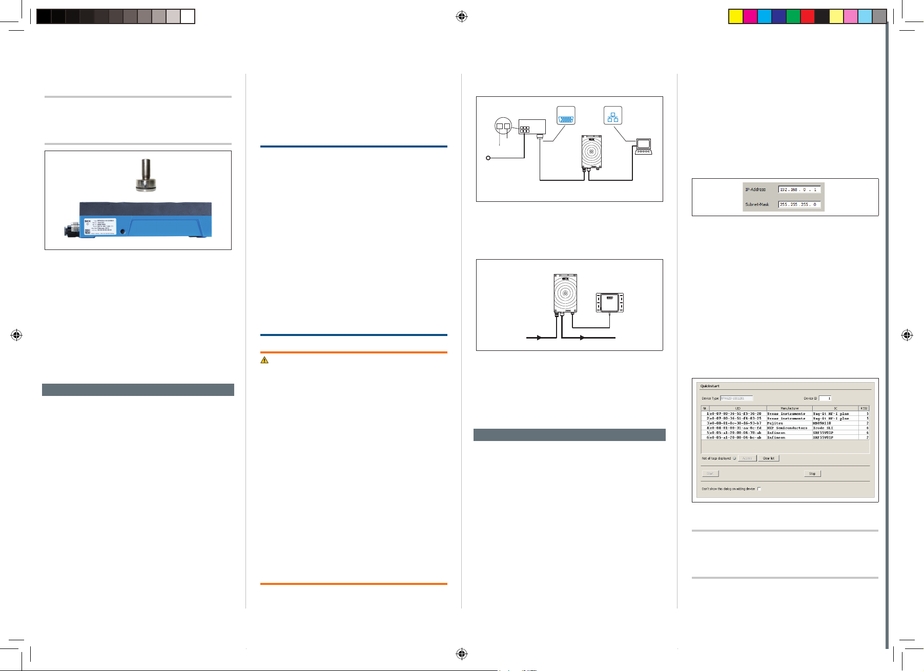
1. Connect the communication interface (e.g., Ethernet) of the device directly to the PC.
CDB620-001
(optional)
1
2
...
...
GND
V
S
S
Fig. 2: Electrical connection block diagram of the device for
commissioning in the default conguration
SerialSerial
RFH630-1102101S05
"Power/
Serial Data/
CAN/I/O"
e.g. cable
No. 2055419 (2 m)
EthernetEthernet
Configuratio
"Ethernet"
(Aux, Host)
e.g. cable
No. 6034414 (2 m)
Diagnostics
SOPASSOPAS
PC
2. If an external antenna is being used (e.g.,
RFA332-2032, part no. 1054399), connect it to
the antenna connection on the device.
External antenna
RFA332-2032
HOSTPower
Fig. 3: Device with RFA332-2032 external antenna
3. If necessary, connect a read pulse sensor, such
as a photoelectric sensor, to the “IN 1” switching
input of the CDB620-001.
4. Supply power to the device.
After successful initialization, the “Ready” LED
illuminates green.
Step 3: Conguration with PC
The SOPAS ET conguration software is used by
default to adjust the device parameters to the application and to the diagnostics in case of error.
a. Installing and starting the SOPAS ET
conguration software
1. Download and install the software from the relevant SICK product page on the Internet at
www.sick.com/SOPAS_ET:
• Latest version of the conguration software
• Current device description le (*sdd) for the
device.
2. For the conguration software, select the
“Complete” option as selected by the installation
wizard. Administrator rights may be required on
the PC to install the software.
3. Start the “SOPAS ET” program option after com-
pleting the installation. Path: Start > Programs >
SICK > SOPAS ET Engineering Tool > SOPAS.
4. Establish a connection between SOPAS ET and he
device via the automatically opened wizard. To do
so, select the device under the devices available
depending on the connected communication
interface, e.g., Ethernet.
5. The following IP address is congured by default
on the RFH630-1102101S05:
Fig. 4: Default IP address
6. SOPAS ET establishes communication with the
device and loads the associated device descrip-
tion le for the device. The
b. Identifying a transponder in Quickstart
mode
tab opens.
1. Bring one or more standards-compliant HF transponders into the working area of the internal antenna or, where applicable, the external antenna
of the device.
2. Click the “Start” button in the
tab in
SOPAS ET. SOPAS ET generates read pulses
continuously and lists the identied transponders
one after the other in the
window.
Fig. 5: SOPAS ET: Display of six identied transponders in the
Important!
window
The automatic triggering in Quickstart mode is intended for initial commissioning and not for permanent
use when operating the device under real conditions.
8023443/11W0/2018-11-20 • Subject to change without notice • SICK AG • Waldkirch • Germany • www.sick.com 2RFH6XX | SICK
8023443-11W0_QS_RFH630-1102101S05_EN_201801120_final.indd 2 23.11.2018 11:27:10
Page 3
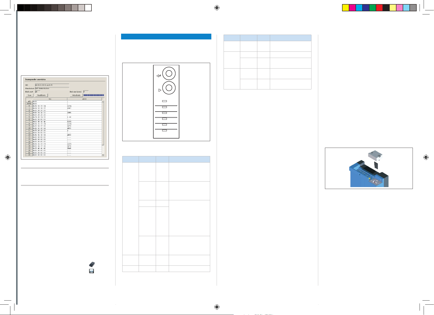
c. Accessing the data on a transponder
stop
Quickstart
transponder access
tran
sponder user data
transponder user data
parameters
1. In order to access the memory area of a transponder, click the
button in
.
2. Highlight the desired transponder (click it with the
mouse).
3. Click the
button. The
tab displays the content of the
selected transponder.
Fig. 6: SOPAS ET:
Important!
The UID (Unique Identier) of the transponder cannot
display window
be changed.
d. Continuing the conguration
1. Under SOPAS ET in the left-hand navigation tree,
edit the required tabs for the application using
the additional entries under
. These
include transponder processing, object trigger
control (e.g., via “Sensor 1” switching input), data
processing and output, data output interface(s),
and the function of the switching inputs and
outputs.
2. Test and, if necessary, modify the settings made
when operating the system under real conditions.
e. Completing the conguration
Permanently save the entire conguration once it
has been successfully tested:
Parameter set in the device: Click the
Conguration le on the PC: Click the
button.
button.
Device description
Device layout
- See “Device layout” on page 5.
Status indicators
-
Enter
Stop
Read Diagn
Ready
Result
RF
Data
CAN
LNK TX
TeachIn
Antenna
Sync
Userdef.
Display LED Color Status
Data Flashing Yellow Data transmission via
host interface
CAN Lights up Green CAN interface activated
Flashing Green Data trac via CAN
interface
LNK TX Flashing Green Data trac via Ethernet
interface
Lights up Yellow Physical Ethernet con-
nection
Tab. 1: Status indicators
Overview of interfaces and connection options
- See “Overview of interfaces and connection options” on page 3.
Overview of pin assignments
- See “Overview of pin assignments” on page 6.
MicroSD memory card (optional accessory)
Fig. 7: Optical status indicators
Status indicators on the rst display level
Display LED Color Status
Ready Lights up Green Lights up constantly after
O – Goes out when download-
Flashing Green PROFINET operation
Flashing Red
Flashing Red New rmware installation
Result Lights up Green Successful read process
RF Lights up Green HF eld is switched on
switching on and completion of successful self-test
(device ready)
ing or uploading conguration data from and to
the device
(single port): Flashes cyclically red (long) and green
(short) alternately.
Trying to establish a connection to a PLC (controller) or loss of connection
during operation
after download to device.
Do not turn o the supply
voltage!
(good read, 100 ms)
Function
The device saves its congured parameter values as
a parameter set in its internal permanent memory
on request. A optional plug-in memory card can be
used for additional parameter cloning on an external
device. If the card is available, the device also saves
the internal parameter set on this. To start cloning, save the parameter set in the device using the
SOPAS ET option “Save parameter permanently”. It is
used, among other things, to conveniently transfer the
parameter set to an exchange unit of the same type in
the event of an error.
As an alternative to the memory card, you can use the
optional CMC600 parameter storage module, which
can be used in the optional connection module, e.g,
CDB620-001 or CDM420-0001.
If both the memory card and the parameter storage
module are available, the device adopts the parameter set from the CMC600 parameter storage module
on restarting.
The rst time a parameter set is stored, we recommend that an empty memory card is used (if necessary, check and delete the contents of the card on the
PC using a card reader).
The memory card is not included with delivery.
on the Internet at www.sick.com/RFH6xx.
The memory card has no write protection that can be
activated.
Inserting the memory card
To avoid damaging the memory card, make sure
there is no power to the device when you insert or
remove it.
The card slot can be accessed on the device behind
the aluminum cover. - See ß, “Device layout” on
page 5.
Maintaining the IP 67 enclosure rating: - See “Safety
information” on page 1.
1. Turn o the supply voltage to the device.
2. To remove the cover, unscrew both Allen screws
(A/F 2).
3. Making sure it is in the correct position (with the
contacts pointing to the front and down – see the
symbol on the device), insert the memory card
into the card slot until it locks into place.
4. Screw the aluminum cover back on.
5. Turn on the supply voltage to the device.
Fig. 8: Inserting the memory card
6. Once it is switched on, the device automatically
detects the presence of a memory card and,
depending on the card's content, behaves as
follows:
• If the card is empty or if it contains a parame-
ter set that cannot be interpreted by the device,
the device saves its currently valid internal
parameter set to the card and starts with this
parameter set.
• If the card contains a parameter set that can
be interpreted by the device, the device permanently overwrites the currently valid internal
parameter set with this external parameter set.
The goal is for the internal parameter set and
the parameter set saved externally to always
be identical.
Only use types approved by SICK to ensure reliable
function of the memory card. See SICK product page
8023443/11W0/2018-11-20 • Subject to change without notice • SICK AG • Waldkirch • Germany • www.sick.com 3RFH6XX | SICK
8023443-11W0_QS_RFH630-1102101S05_EN_201801120_final.indd 3 23.11.2018 11:27:13
Page 4

NOTE
Risk of data loss or irreparable damage to the
memory card!
The device does not signal the respective access to
the card used (read/write).
If the parameter set is saved with the option
“Save parameter permanently” in the device using
SOPAS ET, do not remove the memory card during
the process and do not switch o the supply voltage.
Technical data (excerpt)
Type RFH630-1102101S05
Product
category
Carrier frequency
Air interface
protocol
Transmitting
power
Scanning range
write/read
Transmission
rate air interface
Typical access
times
Host
interfaces
Host interfaces
(also over external modules)
Aux interfaces
(for conguration)
SICK CAN Sensor Network
Switching inputs
ISO/IEC-15693 compatible read/write
unit
HF (13.56 MHz)
ISO/IEC 15693, 18000-3 M1 (“mandatory” and “optional” command set)
1 W
Internal antenna: max. 10 mm
1)
26 kBit/s
UID read (64 bit/8 byte): 18 ms
1 block read (32 bit/4 byte): 13 ms
1 Block write (32 bit/4 byte): 16 ms
RS-232/422 (0.3 kBd … 115.2 kBd)
Ethernet TCP/IP (10/100 MBit/s)
EtherNet/IP™ (10/100 MBit/s)
PROFINET (single port, 10/100 MBit/s)
CANopen (20 ... 1,000 kBd)
PROFIBUS via CDF600-2 PROFIBUS
PROFINET via CDF600-2 PROFINET
Dual Port
®
EtherCAT
via CDF600 EtherCAT®
RS-232 (57.6 kBd)
Ethernet TCP/IP (10/100 MBit/s)
Via CAN interface
2 x IN (V
= max. 32 V, Iin = max. 5 mA),
in
opto-decoupled, adjustable debounce
time.
2 additional inputs via opitonal CMC600 module in optional
CDB620-001 module
Type RFH630-1102101S05
Switching
outputs
Optical indicators
Function key 2 x, Read Diagnosis, additional func-
Parametric data
backup
Supply voltage
V
S
Power consumption
Electrical connections
Housing Aluminum die cast, plastic (PPS)
Weight 712 g
Safety
Enclosure rating
Protection class
EMC
Shock
resistance
Shock resistance
Radio equipment approval
Ambient temperature
Relative humidity
1) With RFID transponder in plane parallel alignment to device antenna; depending on dimensions and quality of transponder.
Tab. 2: Technical specications
2 x OUT (each I
trically isolated from the supply voltage,
short-circuit protected, temperature
protected.
2 additional outputs via optional CMC600 module in optional
CDB620-001 module
6 x status indicators LEDs (Ready,
Result, RF, Data, CAN, LNK TX)
tions can be adjusted via SOPAS ET
MicroSD card (optional) or external via
optional CMC600 module in optional
CDB620-001 connection module
10V DC ... 30 V DC, ES1 in accordance
with currently applicable EN 62368-1
Max. < 6 W (with switching outputs
without load)
1 x male connector, M12, 17-pin,
A-coded
1 x female connector, M12, 4-pin,
D-coded
1 x female connector, TNC reverse
EN 62368-1
IP 67 (EN 60529:1991-10/
A2:2000-02)
III, (EN 61140:2011-01)
EN 301489-3 Receiver Class 2
EN 60068-2-6:2008-02
EN 60068-2-27:2009-05
Europe EN 300 330-2 /
FCC Part 15
Operation: –20 °C ... +50 °C
Storage: –25 °C ... +70 °C
0% ... 95%, non-condensing
≤ 100 mA), not elec-
out
For further technical specications, see the online
data sheet on the product page on the Internet at
www.sick.com/RFH6xx.
Regulatory notes
Europe: Simplied EU declaration of conformity
SICK AG hereby declares that the
RFH630-1102101S05 radio equipment complies
with the 2014/53/EU directive. The complete text of
the EU declaration of conformity is available at the
following web address: www.sick.com/RFH6xx.
FCC approval
The device fullls Part 15 of the FCC regulations:
The following prerequisites must be met:
• This device may not cause harmful interference,
and this device must accept any interference
received, including interference that may cause
undesired operation.
• Any changes or modications not expressly ap-
proved by the party responsible for compliance
could void the user's authority to operate this
device.
Operational restrictions
• USA: To comply with FCC part 15 rules in the United
States, the system must be professionally installed
to ensure compliance with the Part 15 certication.
It is the responsibility of the operator and profes-
sional installer to ensure that only certied systems
are deployed in the United States.
The use of the system in any other combination
(such as co-located antennas transmitting the
same information) is expressly forbidden.
This equipment has been tested and found to
comply with the limits for a Class A digital device,
pursuant to part 15 of the FCC Rules. These limits
are designed to provide reasonable protection
against harmful interference when the equipment
is operated in a commercial environment. This
equipment generates, uses, and can radiate radio
frequency energy and, if not installed and used in
accordance with the instruction manual, may cause
harmful interference to radio communications.
Operation of this equipment in a residential area is
likely to cause harmful interference in which case
the user will be required to correct the interference
at his own expense. Changes or modications not
expressly approved by the party responsible for
compliance could void the user’s authority to operate the equipment.
• USA/Canada: This device complies with part 15 of
the FCC Rules and Industry Canada licence-exempt
RSS standard(s) Operation is subject to the follow-
ing two conditions: (1) This device may not cause
harmful interference, and (2) this device must
accept any interference received, including interference that may cause undesired operation.
• Canada: This equipment complies with FCC radiation exposure limits set forth for an uncontrolled
environment. This equipment should be installed
and operated with minimum distance 20 cm between the radiator & your body. This Class A digital
apparatus complies with Canadian ICES-003.
This radio transmitter has been approved by
Industry Canada to operate with the antenna types
listed below with the maximum permissible gain
and required antenna impedance for each antenna
type indicated.
Antenna types not included in this list, having a
gain greater that the maximum gain indicated for
that type, are strictly prohibited for use with this
device.
• Internal antenna:
Maximum permissible antenna gain: 2 dBi
Required impedance: 50 Ohm
• External antenna RFA332:
Maximum permissible antenna gain: 2 dBi
Required impedance: 50 Ohm
• Under industry Canada regulations, this radio
transmitter may only operate using an antenna
of a type and maximum (or lesser) gain approved
for the transmitter by Industry Canada. To reduce
potential radio interference to other users, the
antenna type and its gain should be so chosen that
the equivalent isotropically radiated power (e.i.r.p.)
is not more than that necessary for successful
communication.
• Canada: This equipment complies with the Industry
Canada RSS standards for license-exempt radio
devices. Operation is subject to the following two
conditions: (1) The device may not cause harmful
interference, and (2) the device must accept any
interference received, including if this may cause
undesired operation. This equipment complies with
the IC radiation exposure limits for uncontrolled
environments. This equipment should be installed
and used with a minimum distance of 20 cm between the radiator and the human body.
• This Class A digital equipment complies with the
Canadian standard NMB-003..
Maintenance and care
The device does not contain any components that
require maintenance.
8023443/11W0/2018-11-20 • Subject to change without notice • SICK AG • Waldkirch • Germany • www.sick.com 4RFH6XX | SICK
8023443-11W0_QS_RFH630-1102101S05_EN_201801120_final.indd 4 23.11.2018 11:27:13
Page 5

Transport and storage
Transport and store the device in the original packaging, with protective plugs and caps fully screwed on.
Do not store outdoors. To ensure that any residual
moisture present can escape, do not store the device
in airtight containers. Do not expose to any aggressive
substances. Storage conditions: Dry, dust-free, no
direct sunlight, as little vibration as possible, storage
temperature –25 °C to +70 °C, relative humidity
max. 95% (non-condensing).
Repairs
Repair work on the device may only be performed by
qualied and authorized service personnel from SICK
AG.
Disassembly and disposal
Any device which can no longer be used must be
disposed of in an environmentally friendly manner in
accordance with the respective applicable country-
specic waste disposal regulations. The device is
electronic waste and must under no circumstances
be disposed of with general waste!
Sources for additional information
You can obtain the Quickstart and further documentation online.
Select your country and language at
www.sick.com.
Enter the devices type designation or part num-
ber into the search eld.
Select the required device.
All documentation and other downloadable
content relating to the device can be found under
Downloads.
The SOPAS ET conguration software can be
downloaded under Software.
Documentation for the accessories that can be
used can be downloaded under Accessories.
Function blocks for the device
www.sick.com/software
Documents on request
• Overview of the device command language
Support is also available from your sales partner:
www.sick.com/worldwide.
Device layout
1
100 (3.94)
147 (5.79)
17.4
(0.69)
10.4 (0.44)
20.6
(0.81)
54.5 (2.15)
39.3
12.3
(0.48)
(1.55)
6.5
(0.26)
16.1
(0.63)
9
8
Fig. 9: Dimensions (in mm) and device structure
1. 4 x M6 threaded mounting holes, 6.5 mm depth
2. 2 x M5 through holes, 4.5 mm, as an alternative for
mounting the device
3. Connection for external antenna (female connector, TNC
reverse)
4. “Ethernet” connection (female connector, M12, 4-pin,
D-coded)
5. Swivel connector
6. Function keys ▾ (Step) and p (Enter)
7. 6 x RGB LEDs, multi-colored (status indicators)
8. Slot for microSD memory card, behind screw-mounted
cover
9. “Power/Serial Data/CAN/I/O” connection (male connec-
tor, M12, 17-pin, A-coded)
71.9 (2.83)
87.5 (3.44)
Enter
mircoSD
2
7.8
100 (3.94)
30 (1.18)
(0.31)
12.5
(0.49)
6.4 (0.25)
9.1 (0.36)
1
(5.5)
139.6
3
2
4
5
6
7
Sync
TeachIn
Userdef.
Antenna
Read Diagn
Stop
Ready
Result
LNK TX
CAN
Data
RF
8023443/11W0/2018-11-20 • Subject to change without notice • SICK AG • Waldkirch • Germany • www.sick.com 5RFH6XX | SICK
8023443-11W0_QS_RFH630-1102101S05_EN_201801120_final.indd 5 23.11.2018 11:27:15
Page 6

Overview of all interfaces and connection options
CDB620-001 (optional)
1
2
GND
V
S
V
S
Switching input 1
(e. g. external reading clock)
Switching input 2
(e. g. incremental encoder)
Switching output 1
(e. g. LED)
Switching output 2
Additional external inputs / outputs via
optional parameter storage module CMC600
in connection module CDB620
Switching input / output = digital
CMC600
...
...
"Power/Serial Data/CAN/I/O"
Adapter cable (female connector, M12,
17-pin, A-coded / male connector,
"Serial RS-232/422" (Host 1), read result alternative to Ethernet
SerialSerial
"Serial RS-232" (Aux 1), alternative to Ethernet Aux port
Null modem cable (female connector, D-Sub, 9-pin /
female connector, D-Sub, 9-pin), TxD and RxD crossed
RFH630-1102101S05
External antenna (optional),
e.g. RFA332)
(Aux 1, Host 1)
D-Sub-HD, 15-pin)
"Ethernet" (Aux 2)
"Ethernet" (Host 2)
read result
Adapter cable (male connector,
M12, 4-pin, D-coded /
male connector, RJ-45, 8-pin)
EthernetEthernet
SOPASSOPAS
Configuration
Diagnostics
HOST
Further data
processing
PC
Overview of pin assignments
Connection "Ethernet"
43
female connector,
M12, 4-pin, D-coded
2
1
1
TD+
2
RD+
3
TD–
4
RD–
Connection "Power/Serial Data/CAN/I/0"
12
3
2
13
4
5
14
6
17
7
1
male connector, M12,
11
10
17-pin, A-coded
16
9
8
15
1
GND
2
V
S
3
CAN L
4
CAN H
5
TD+ (RS-422), Host
6
TD– (RS-422),
TxD (RS-232), Host
7
TxD (RS-232), Aux
8
RxD (RS-232), Aux
9
SensGND
10
Sensor 1 (switching input 1)
11
RD+ (RS-422), Host
12
RD– (RS-422),
RxD (RS-232), Host
13
Result 1 (switching output 1)
14
Result 2 (switching output 2)
15
Sensor 2 (switching input 2)
16
n.c.
17
n.c.
8023443/11W0/2018-11-20 • Subject to change without notice • SICK AG • Waldkirch • Germany • www.sick.com 6RFH6XX | SICK
8023443-11W0_QS_RFH630-1102101S05_EN_201801120_final.indd 6 23.11.2018 11:27:16
Page 7

(Blank page)
8023443/11W0/2018-11-20 • Subject to change without notice • SICK AG • Waldkirch • Germany • www.sick.com 7RFH6XX | SICK
8023443-11W0_QS_RFH630-1102101S05_EN_201801120_final.indd 7 23.11.2018 11:27:16
Page 8

(Blank page)
8023443/11W0/2018-11-20 • Subject to change without notice • SICK AG • Waldkirch • Germany • www.sick.com 8RFH6XX | SICK
8023443-11W0_QS_RFH630-1102101S05_EN_201801120_final.indd 8 23.11.2018 11:27:16
8023443/11W0/2018-11-20 • 8M_TM • Printed in Germany • All rights reserved • Subject to change without notice
 Loading...