

Page 1
ReLy OSSD1
Safety relay
O P E R A T I N G I N S T R U C T I O N S
Page 2

Described product
R
eLy OSSD1
Manufacturer
SICK AG
Erwin-Sick-Str. 1
79183 Waldkirch
Germany
Legal information
his work is protected by copyright. Any rights derived from the copyright shall be
T
reserved for SICK AG. Reproduction of this document or parts of this document is only
permissible within the limits of the legal determination of Copyright Law. Any modifica‐
tion, abridgment or translation of this document is prohibited without the express writ‐
ten permission of SICK AG.
The trademarks stated in this document are the property of their respective owner.
© SICK AG. All rights reserved.
Original document
T
his document is an original document of SICK AG.
2
O PE R AT I NG IN S TR U CT I ON S | ReLy OSSD1 8020860/ZX84/2018-11-15 | SICK
Subject to change without notice
Page 3

Contents
CONTENTS
1 About this document........................................................................ 5
1.1 Purpose of this document........................................................................ 5
1.2 Scope......................................................................................................... 5
1.3 Target groups and structure of these operating instructions................ 5
1.4 Additional information.............................................................................. 5
1.5 Symbols and document conventions...................................................... 6
2 Safety information............................................................................ 7
2.1 General safety notes................................................................................ 7
2.2 Intended use............................................................................................. 7
2.3 Improper use............................................................................................. 7
2.4 Requirements for the qualification of personnel.................................... 8
3 Product description........................................................................... 9
3.1 Construction and function........................................................................ 9
3.2 Product characteristics............................................................................ 9
3.2.1 Device overview....................................................................... 9
3.2.2 Interfaces................................................................................. 9
3.2.3 Compatible sensor types......................................................... 9
3.2.4 External device monitoring...................................................... 10
3.2.5 Status indicators...................................................................... 10
4 Project planning................................................................................ 11
4.1 Manufacturer of the machine.................................................................. 11
4.2 Operating entity of the machine.............................................................. 11
4.3 Design........................................................................................................ 11
4.4 Electrical integration................................................................................. 12
4.4.1 Enabling current paths............................................................ 12
4.4.2 Feedback current path............................................................ 12
4.4.3 Connection diagrams.............................................................. 13
4.5 Testing plan............................................................................................... 13
4.5.1 Minimum requirements for the regular thorough check....... 13
5 Mounting............................................................................................. 14
5.1 Safety......................................................................................................... 14
5.2 Mounting procedure................................................................................. 14
5.3 Disassembly.............................................................................................. 15
5.4 Device replacement.................................................................................. 15
6 Electrical installation........................................................................ 17
6.1 Device connection.................................................................................... 17
7 Commissioning.................................................................................. 19
7.1 Safety......................................................................................................... 19
7.2 Thorough check........................................................................................ 19
8020860/ZX84/2018-11-15 | SICK O P ER A TI N G I NS T RU C TI O NS | ReLy OSSD1
Subject to change without notice
3
Page 4

CONTENTS
8 Troubleshooting................................................................................. 20
8.1 Safety......................................................................................................... 20
8.2 Status indicator (LED)............................................................................... 20
9 Decommissioning............................................................................. 21
9.1 Protecting the environment...................................................................... 21
10 Technical data.................................................................................... 22
10.1 Data sheet................................................................................................. 22
10.2 Dimensional drawings.............................................................................. 26
10.3 Internal circuitry........................................................................................ 27
11 Ordering information........................................................................ 28
11.1 Ordering information for ReLy.................................................................. 28
12 Annex.................................................................................................. 29
12.1 Compliance with EU directives................................................................. 29
13 List of figures..................................................................................... 30
14 List of tables....................................................................................... 31
4
O PE R AT I NG IN S TR U CT I ON S | ReLy OSSD1 8020860/ZX84/2018-11-15 | SICK
Subject to change without notice
Page 5
ABOUT THIS DOCUMENT 1
1 About this document
1.1 Purpose of this document
These operating instructions contain the information required during the life cycle of the
afety relay.
s
These operating instructions must be made available to everyone who works with the
safety relay.
1.2 Scope
This document only applies to a ReLy safety relay with the following type label entries in
t
he Operating Instructions field:
8020858
•
1.3 Target groups and structure of these operating instructions
These operating instructions are intended for the following target groups: project devel‐
s (planners, developers, designers), installers, electricians, safety experts (such as
oper
CE authorized representatives, compliance officers, people who test and approve the
application), operators, and maintenance personnel.
These operating instructions are organized by the life phases of the device: project
planning, mounting, electrical installation, commissioning, operation and maintenance.
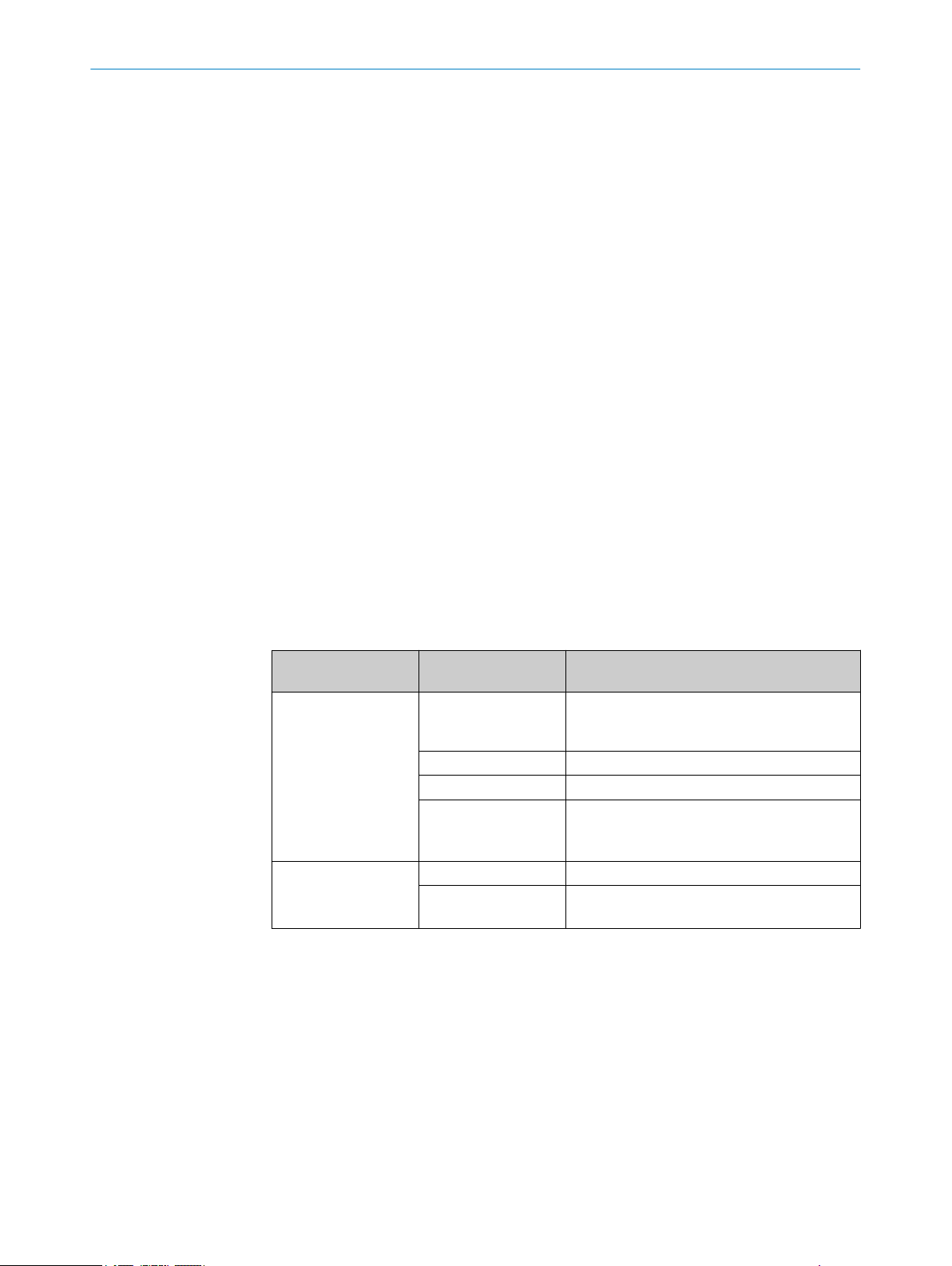
The table below shows the target groups and how – for many applications – these are
typically divided up between the manufacturer and the entity operating the machine in
which the device is to be integrated:
Area of responsibility Target group Specific chapters of these operating instruc‐
Manufacturer Project developers
(planners, developers,
designers)
Installers "Mounting", page 14
Electricians "Electrical installation", page 17
Safety experts "Project planning", page 11
Operating entity Operators "Troubleshooting", page 20
Maintenance person‐
l
ne
1)
Chapters not listed here are intended for all target groups. All target groups must follow all of the safety
and w
arning instructions in all chapters of the operating instructions!
1)
ions
t
"Project planning", page 11
"Technical data", page 22
ommissioning", page 19
"C
"Technical data", page 22
"Troubleshooting", page 20
"Ordering information", page 28
In other applications, the operating organization is also the manufacturer of the equip‐
ment w
ith the corresponding allocation of the target groups.
1.4 Additional information
www.sick.com
T
he following information is available on the Internet:
This document in other languages
•
Data sheets and application examples
•
CAD data and dimensional drawings
•
8020860/ZX84/2018-11-15 | SICK O P ER A TI N G I NS T RU C TI O NS | ReLy OSSD1
Subject to change without notice
5
Page 6
1 ABOUT THIS DOCUMENT
ertificates (e.g. EU declaration of conformity)
C
•
Guide for Safe Machinery Six steps to a safe machine
•
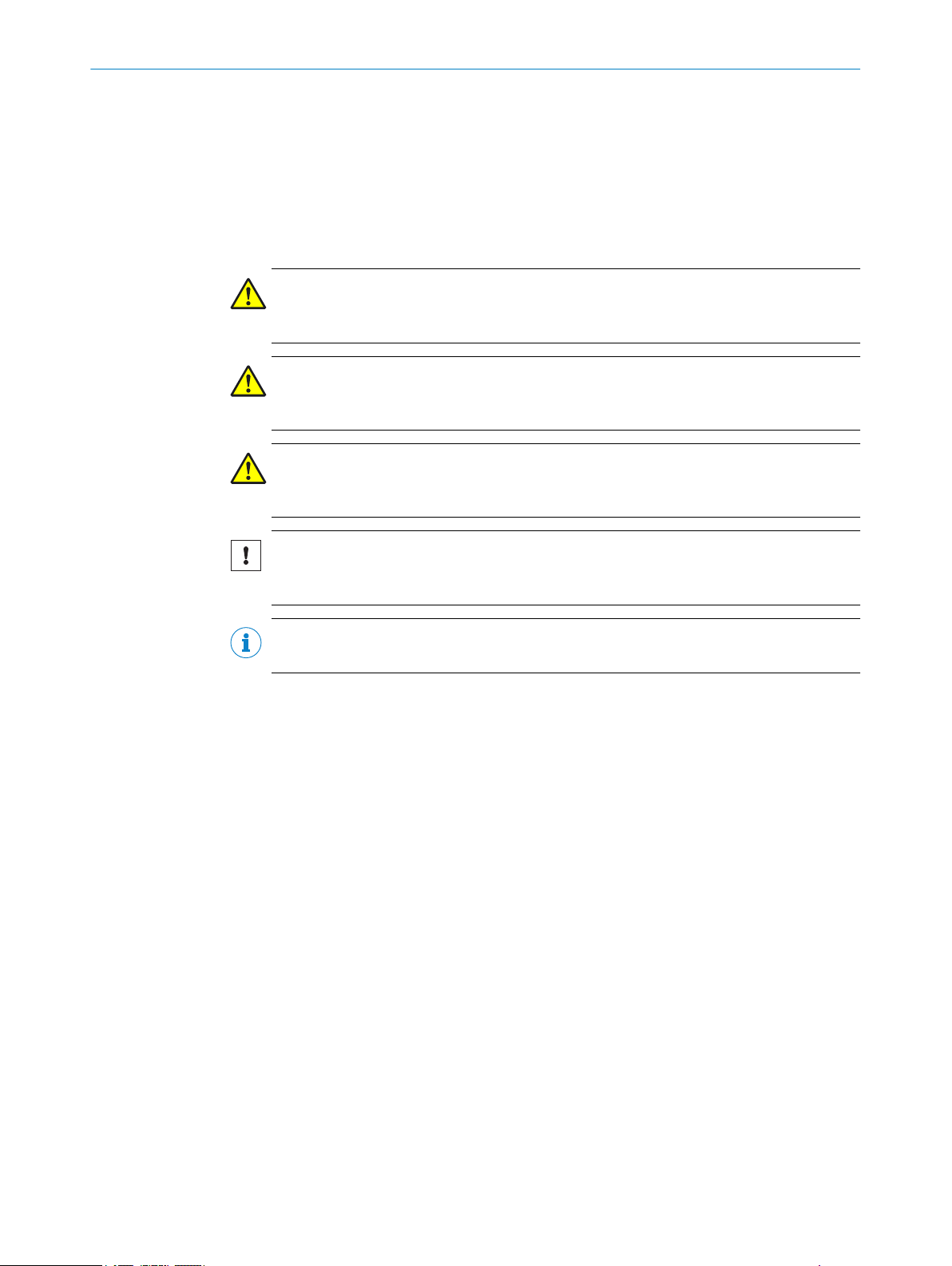
1.5 Symbols and document conventions
The following symbols and conventions are used in this document:
Safety notes and other notes
DANGER
ates a situation presenting imminent danger, which will lead to death or serious
Indic
injuries if not prevented.
WARNING
Indic
ates a situation presenting possible danger, which may lead to death or serious
injuries if not prevented.
CAUTION
Indic
ates a situation presenting possible danger, which may lead to moderate or minor
injuries if not prevented.
NOTICE
ates a situation presenting possible danger, which may lead to property damage if
Indic
not prevented.
NOTE
ates useful tips and recommendations.
Indic
Instructions to action
The arrow denotes instructions to action.
b
1. The sequence of instructions for action is numbered.
2. Follow the order in which the numbered instructions are given.
✓
The check mark denotes the result of an instruction.
LED symbols
These symbols indicate the status of an LED:
The LED is off.
o
The LED is flashing.
Ö
The LED is illuminated continuously.
O
6
O PE R AT I NG IN S TR U CT I ON S | ReLy OSSD1 8020860/ZX84/2018-11-15 | SICK
Subject to change without notice
Page 7
2 Safety information
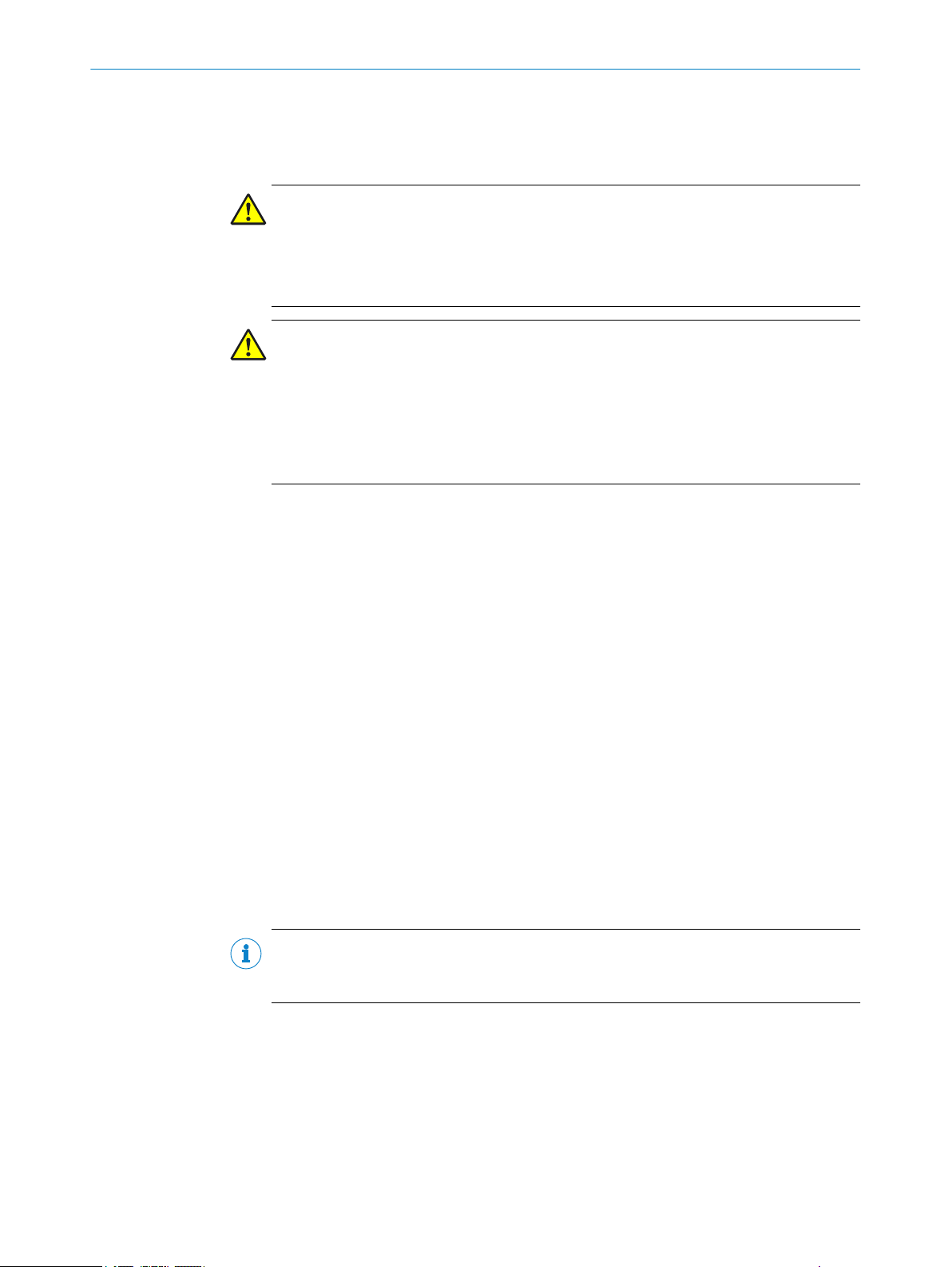
2.1 General safety notes
DANGER
If t
he safety component is integrated incorrectly, the dangerous state may be ended to
late.
Plan the integration of the safety component in accordance with the machine
b
requirements, see "Project planning", page 11.
DANGER
azard due to lack of effectiveness of the protective device
H
In the case of non-compliance, it is possible that the dangerous state of the machine
may not be stopped or not stopped in a timely manner.
Please read this document carefully and make sure that you understand the con‐
b
tent fully before working with the device.
Follow all safety notes in this document.
b
Improper installation or manipulation can lead to serious injuries.
SAFETY INFORMATION 2
2.2 Intended use
The safety relay is an expansion module for sensors or safety devices with OSSDs for
s
The safety relay complies with class A, group 1 as per EN 55011. Group 1 encom‐
passes all ISM devices in which intentionally generated and/or used conductor-bound
RF energy that is required for the inner function of the device itself occurs.
The safety relay must only be used within the limits of the prescribed and specified
technical data and operating conditions at all times.
Incorrect use, improper modification or manipulation of the safety relay will invalidate
any warranty from SICK; in addition, any responsibility and liability of SICK for damage
and secondary damage caused by this is excluded.
UL/CSA applications
If t
ing conditions must also be met:
•
NOTE
T
UL 508, general applications.
witching safety-related circuits on and off.
he product is being used in accordance with UL 508 or CSA C22.2 No. 14, the follow‐
To protect the device’s 24-volt voltage supply, use a fuse with a maximum voltage
of 4 A and a minimum of 30 V DC in accordance with UL 248.
he safety functions have not be evaluated by UL. Authorization is in accordance with
2.3 Improper use
The safety relay is no
At altitudes of over 4,000 m above sea level
•
In explosion-hazardous areas
•
8020860/ZX84/2018-11-15 | SICK O P ER A TI N G I NS T RU C TI O NS | ReLy OSSD1
Subject to change without notice
t suitable for the following applications (this list is not exhaustive):
7
Page 8

AFETY INFORMATION
2 S
2.4 Requirements for the qualification of personnel
The protective device must be configured, installed, connected, commissioned, and ser‐
iced by qualified safety personnel only.
v
Project planning
For project planning, a person is considered competent when he/she has expertise and
experience in the selection and use of protective devices on machines and is familiar
with the relevant technical rules and national work safety regulations.
Mechanical mounting, electrical installation, and commissioning
For the task, a person is considered qualified when he/she has the expertise and expe‐
rience in the relevant field and is sufficiently familiar with the application of the protec‐
tive device on the machine to be able to assess whether it is in an operationally safe
state.
Operation and maintenance
For operation and maintenance, a person is considered competent when he/she has
the expertise and experience in the relevant field and is sufficiently familiar with the
application of the protective device on the machine and has been instructed by the
machine operator in its operation.
8
O PE R AT I NG IN S TR U CT I ON S | ReLy OSSD1 8020860/ZX84/2018-11-15 | SICK
Subject to change without notice
Page 9
3 Product description
1
3
2
3
3
1
I1
14
2
4
3
2
I2
A2
RELY
1
2
3
4
CH1
CH2
3.1 Construction and function
The safety relay ReLy OSSD1 is an electrical switching device with inputs and outputs.
he safety capable inputs of the safety relay are connected to safety sensors.
T
2 safety capable inputs control the internal relays, which are used to reliably switch the
enabling current paths.
Actuators with positively guided contacts are connected to the enabling current paths.
3.2 Product characteristics
3.2.1 Device overview
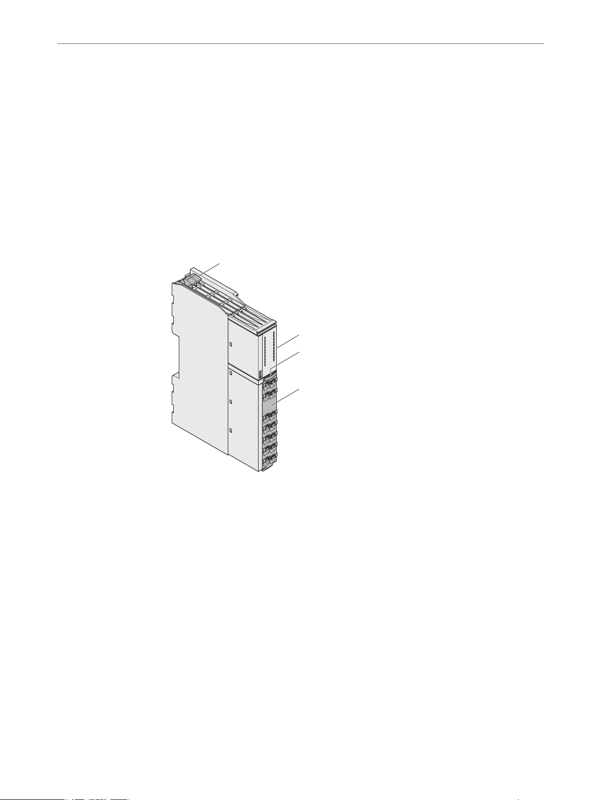
PRODUCT DESCRIPTION 3
Figure 1: Device overview
Device unlocking
1
LEDs
2
Front connector unlocking
3
Front connector
4
3.2.2 Interfaces
Inputs
•
2 s
afety capable inputs
Outputs
2 enabling current paths (safe)
•
Feedback current path (for use as external device monitoring, not safe)
•
3.2.3 Compatible sensor types
8020860/ZX84/2018-11-15 | SICK O P ER A TI N G I NS T RU C TI O NS | ReLy OSSD1
Subject to change without notice
The safety relay adds an OSSD output to safety sensors or safety components. e.g.:
lectro-sensitive protective equipment (ESPE) with a single-channel or dual-chan‐
E
•
nel monitored active switching output with cross-circuit detection (OSSD)
Safety controllers with monitored semi-conductor outputs
•
9
Page 10

CH1
CH2
13
23
31
I1
14
24
32
I2
A2
RELY
1
3
2
3
3
1
I1
14
2
4
3
2
I2
A2
RELY
CH1
CH2
OSSD1
1085343
3 P
RODUCT DESCRIPTION
3.2.4 External device monitoring
The feedback current path is used as external device monitoring for the monitoring by
t
he base device.
3.2.5 Status indicators
LEDs
Figure 2: LEDs
The labeled positions are only partially assigned LEDs. The positions and their labeling
(except for the upper 2 lines) also show the pin assignment of the terminals on the front
connector.
Table 1: Safety relay indicators
Labeling Color Function
CH1 Green OSSD 1 safety capable input
CH2 Green OSSD 2 safety capable input
Further topics
atus indicator (LED)", page 20
"St
•
10
O PE R AT I NG IN S TR U CT I ON S | ReLy OSSD1 8020860/ZX84/2018-11-15 | SICK
Subject to change without notice
Page 11

4 Project planning
4.1 Manufacturer of the machine
DANGER
F
ailure to comply with manufacturer’s obligations
Hazard due to lack of effectiveness of the protective device
Carry out a risk assessment before using the safety relay.
b
Do not manipulate, open or modify the components of the safety relay.
b
Make sure the safety relay is only repaired by the manufacturer or by someone
b
authorized by the manufacturer. Improper repair can lead to a loss of the protec‐
tive function.
4.2 Operating entity of the machine
DANGER
F
ailure to observe operator obligations
Hazard due to lack of effectiveness of the protective device
PROJECT PLANNING 4
4.3 Design
Changes to the machine and changes to the mechanical mounting of the safety
b
relay necessitate a new risk assessment. The results of this risk assessment may
require the entity operating the machine to meet the obligations of a manufac‐
turer.
Apart from the procedures described in this document, the components of the
b
safety relay must not be opened or modified.
Do not carry out any repair work on components. Improper repair of the safety
b
relay can lead to a loss of the protective function.
The safety relay must be installed in a control cabinet with an enclosure rating of IP54
or higher.
The safety relay must be installed on a mounting rail (35 mm) in accordance with IEC
60715.
Space requirements in the control cabinet
T
o ensure sufficient air circulation and cooling, sufficient distance must be kept in the
control cabinet above and below the safety relay.
Sufficient distance must be kept for the connected cables before the safety relay (front
side).
8020860/ZX84/2018-11-15 | SICK O P ER A TI N G I NS T RU C TI O NS | ReLy OSSD1
Subject to change without notice
11
Page 12

≥ 50≥ 50
≥ 25
4 PROJECT PLANNING
Figure 3: Distances in control cabinet
R
equired distance:
Above and below the safety relay: ≥ 50 mm
•
In front of the safety relay: ≥ 25 mm
•
4.4 Electrical integration
Important information
NOTE
he device achieves overvoltage category III if feedback current path 31/32 is supplied
T
by the same voltage supply as the upstream OSSDs (safety extra-low voltage). Con‐
nected devices must be also have overvoltage category III.
4.4.1 Enabling current paths
DANGER
azard due to lack of effectiveness of the protective device
H
Ensure the enabling current paths are supplied by the same voltage supply.
4.4.2 Feedback current path
b
12
The feedback current path is used as external device monitoring for the monitoring by
he base device.
t
The status of the feedback current path (31, 32) changes as soon as the safe enabling
current paths (13, 14, 23, 24) switch. The feedback current path is not safe.
Table 2: Switching behavior of feedback current path (31, 32)
State of enabling current paths State of feedback current path
Closed Open
Open Closed
O PE R AT I NG IN S TR U CT I ON S | ReLy OSSD1 8020860/ZX84/2018-11-15 | SICK
Subject to change without notice
Page 13

4.4.3 Connection diagrams
3) PELV
F2 F1
+24 V DC
0 V DC
K1K
2
E213418/00/2018-11-15
k2
z
k1 k2
k1
z
x
y
x1)y
32
31I1 I2
24A2 14
23 13
RLY3-OSSD1
System connection
System connection
+24 V DC
deTec4 SP1
2
1
3
5
6
4
7
8
r
RES
ADO
OSSD1
OSSD2
EDM
0 V DC
Com1
s
+24 V DC
n.c
In2
In1
n.c
.
0 V DC
Com1
n.c.
2
3
4
5
6
1
7
8
2)
F0
L+
L–
PROJECT PLANNING 4
Figure 4: ReLy OSSD1 connection diagram
4.5 Testing plan
The safety relay must be thoroughly checked by appropriately qualified safety personnel
during commissioning, after modifications, and at regular intervals, see "Thorough
check", page 19.
The regular thorough checks serve to assess the effectiveness of the safety relay and to
identify defects as a result of modifications or other influences (e.g., damage or manip‐
ulation).
The manufacturer and user must define the type and frequency of the thorough checks
on the machine on the basis of the application conditions and the risk assessment.
Determination of the thorough checks must be documented in a traceable manner.
4.5.1 Minimum requirements for the regular thorough check
The following thorough checks must be carried out at regular intervals:
T
horough check of the housing for damage
•
Thorough check of the cables for damage
•
Thorough check of the safety relay for signs of misuse or manipulation
•
Thorough check of the safety function
•
The minimum test interval depends on the applicable safety capability of the overall
application, see table 5, page 22.
8020860/ZX84/2018-11-15 | SICK O P ER A TI N G I NS T RU C TI O NS | ReLy OSSD1
Subject to change without notice
13
Page 14

Click
5 MOUN
TING
5 Mounting
5.1 Safety
DANGER
H
azard due to unexpected starting of the machine
Hazard due to electrical voltage
Make sure that the outputs of the safety relay have no effect on the machine dur‐
b
ing mounting and electrical installation.
Make sure that the safety relay and the connected components are isolated from
b
all voltage sources during mounting and electrical installation of the device and
during mounting/dismantling of the front connector.
NOTICE
Enclosure rating IP20 only applies if the front connector is mounted.
5.2 Mounting procedure
Prerequisites
ing is done in accordance with EN 50274 and electrical installation in
Mount
•
accordance with IEC 60204-1 in the control cabinet with enclosure rating IP54.
Mounting is done on a 35 mm mounting rail (IEC 60715).
•
The mounting rail is connected to the functional earth.
•
The safety relay is installed in a vertical orientation (on a horizontal mounting rail).
•
There is at least 50 mm of space for air circulation above and below the safety
•
relay.
There is at least 25 mm of space in front of the safety relay (front side). More
•
space may be needed depending on the connections.
Approach
14
Figure 5: Mounting
A
ttach safety relay to mounting rail.
b
O PE R AT I NG IN S TR U CT I ON S | ReLy OSSD1 8020860/ZX84/2018-11-15 | SICK
Subject to change without notice
Page 15

5.3 Disassembly
Approach
MOUNTING 5
Figure 6: Disassembly
1. Press the unlocking mechanism on the upper side of the safety relay towards the
back.
2. Loosen safety relay from the mounting rail.
5.4 Device replacement
Overview
In e
vent of a defect, exchange the device and reuse the front connector with the con‐
nected cables.
Approach
1. Disconnect device and the connected components from all voltage sources.
2. Take front connector with connected cables off the defective device: Press the
unlocking mechanism of the front connector downwards and pull out the front con‐
nector.
8020860/ZX84/2018-11-15 | SICK O P ER A TI N G I NS T RU C TI O NS | ReLy OSSD1
Subject to change without notice
15
Page 16

Click
16
5 MOUN
TING
Figure 7: Dismantling front connector
3. Remove the defective device.
4.
Mount new device.
5. Mount front connector with connected cables to the new device: First mount in the
device with bent hook and then engage in the housing.
Figure 8: Mounting the front connector
✓
T
he front connector engages with an audible click.
16
O PE R AT I NG IN S TR U CT I ON S | ReLy OSSD1 8020860/ZX84/2018-11-15 | SICK
Subject to change without notice
Page 17

6 Electrical installation
6.1 Device connection
Important information
DANGER
H
azard due to unexpected starting of the machine
Hazard due to electrical voltage
Make sure that the outputs of the safety relay have no effect on the machine dur‐
b
ing mounting and electrical installation.
Make sure that the safety relay and the connected components are isolated from
b
all voltage sources during mounting and electrical installation of the device and
during mounting/dismantling of the front connector.
NOTICE
Enclosure rating IP20 only applies if the front connector is mounted.
Prerequisites
ELECTRICAL INSTALLATION 6
E
lectrical installation is done in conformity with IEC 60204-1.
•
The mounting rail is connected to the functional earth.
•
The voltage supply and connected signals meet the requirements for safety extra-
•
low voltage (EN 61140) or NEC Class 2 (UL 1310).
The external voltage supply must be capable of bridging a brief power failure of
•
20 ms as specified in IEC 60204-1. Suitable power supply units are available as
accessories from SICK.
The safety outputs and external device monitoring (EDM) must be wired within the
•
control cabinet.
When using the safety relay with voltages larger than the safety extra-low voltage:
•
The N/C contacts of the controlled contactors must be safely isolated from the
other contactor contacts.
Contact fuse with safety fuse gG or circuit breaker C: 6 A, maximum short-circuit
•
protection I ≤ 400 A.
The ground connection of all connected devices must have the same potential as
•
A2.
All connected devices and the reset pushbutton comply with the required category
•
in accordance with ISO 13849-1 and SILCL in accordance with IEC 62061 (e.g.
outputs which detect cross-circuit, shielded single sheathed cables, separate
installation).
8020860/ZX84/2018-11-15 | SICK O P ER A TI N G I NS T RU C TI O NS | ReLy OSSD1
Subject to change without notice
17
Page 18

6 ELE
CTRICAL INSTALLATION
Pin assignment
Figure 9: Terminals on front connector
T
able 3: Pin assignment of the terminals
Terminal Description
13, 14 1)
23, 24 1)
2)
2)
Enabling current path
Enabling current path
31 Feedback current path, 24 V DC
32 Feedback current path, for connection to the EDM input of
t
he basic device
I1 CH1 input (safety capable input for OSSD 1)
I2 CH2 input (safety capable input for OSSD 2)
3)
A2 Voltage supply 0 V DC
1)
The enabling current paths must be supplied by the same voltage supply.
2)
The enabling current path and external device monitoring (EDM) must be wired within the control cabinet.
3)
With single-channel base device: Connect jumper between I1 and I2.
Complementary information
T
o protect and increase the service life of contact outputs, equip all connected loads
with varistors or RC elements. The response times will increase depending on the sup‐
pressor used.
Further topics
18
"Connection diagrams", page 13
•
O PE R AT I NG IN S TR U CT I ON S | ReLy OSSD1 8020860/ZX84/2018-11-15 | SICK
Subject to change without notice
Page 19

7 Commissioning
7.1 Safety
DANGER
D
angerous state of the machine
During commissioning, the machine or the protective device may not yet behave as you
have planned.
Make sure that there is no-one in the hazardous area during commissioning.
b
7.2 Thorough check
Requirements for the thorough check during commissioning and in certain situations
The device and its application must be thoroughly checked in the following situations:
Before commissioning
•
After changes to the configuration or the safety function
•
After changes to the mounting or the electrical installation
•
After exceptional events, such as after manipulation has been detected, after
•
modification of the machine, or after replacing components
COMMISSIONING 7
The thorough check ensures the following:
All relevant regulations are complied with and the device is effective in all of the
•
machine’s operating modes.
The documentation accurately reflects the state/condition of the machine, includ‐
•
ing the protective device.
The thorough checks must be carried out by qualified safety personnel or specially qual‐
ified and authorized personnel, and must be documented in a traceable manner.
8020860/ZX84/2018-11-15 | SICK O P ER A TI N G I NS T RU C TI O NS | ReLy OSSD1
Subject to change without notice
19
Page 20

8 TROUBLESHOOTING
8 Troubleshooting
8.1 Safety
DANGER
H
azard due to lack of effectiveness of the protective device
In the case of non-compliance, it is possible that the dangerous state of the machine
may not be stopped or not stopped in a timely manner.
Immediately shut the machine down if the behavior of the machine cannot be
b
clearly identified.
If a machine fault cannot be definitively determined or safely rectified, immediately
b
shut the machine down.
Secure the machine so that it cannot switch on unintentionally.
b
NOTE
A
dditional information on troubleshooting can be found at the responsible SICK sub‐
sidiary.
8.2 Status indicator (LED)
Table 4: Operational statuses
LED Status Possible cause
CH1
CH2
O Green
O Gr
een
Voltage on I1
Voltage on I2
20
O PE R AT I NG IN S TR U CT I ON S | ReLy OSSD1 8020860/ZX84/2018-11-15 | SICK
Subject to change without notice
Page 21

9 Decommissioning
9.1 Protecting the environment
The device has been designed to minimize its impact on the environment. It consumes
y a minimum of energy and natural resources.
onl
Always act in an environmentally responsible manner at work. For this reason,
b
please note the following information regarding disposal.
Always dispose of serviceableness devices in compliance with local/national rules and
egulations with respect to waste disposal.
r
NOTE
e will be glad to help you dispose of these devices on request.
W
DECOMMISSIONING 9
8020860/ZX84/2018-11-15 | SICK O P ER A TI N G I NS T RU C TI O NS | ReLy OSSD1
Subject to change without notice
21
Page 22

10 TECHNICAL DATA
10 Technical data
10.1 Data sheet
Table 5: Safety-related parameters
SIL claim limit
C 62061)
(IE
Cate‐
ory (ISO 13849-1)
g
Performance level (ISO
13849-1)
Hardware error toler‐
ance
Maximum test interval
he safety function
of t
MTTFD (single chan‐
nel) (ISO 13849-1)
PFHD (me
For operating
hei
above sea level
PFD
avg
For operating
hei
above sea level
TM (mis
Safe status when a
ault occurs
f
Stop category 0 (IEC 60204-1)
1)
The required safety integration level depends on your application.
2)
In order to reach at least SIL2 / PL, an external diagnosis with DC ≥ 99% must be applied (i.e., external
de
3)
If service life curve is adhered to, see figure 11, page 26.
Table 6: Mechanical data
Desired safety integrity level (IEC 61508)
SIL3 SIL2 SIL1
SILCL3 SILCL2 SILCL1
4 3 3
2)
PL e PL d PL c
1
1 month 1 year –
300 years 100 years 100 years
an probability of a dangerous failure per hour)
1 × 10
-9
1 × 10
-8
ghts ≤ 4,000 m
(mean probability of a dangerous failure on demand)
5 × 10
-5
5 × 10
-4
ghts ≤ 4,000 m
sion time) 20 years (ISO 13849-1)
The safety relay has no internal fault detection and is unable to assume
a safe status in the event of a fault. Fault detection is performed by the
connected safety-related logic unit.
vice monitoring must be connected).
1)
3)
-7
1 × 10
3)
-3
5 × 10
22
Weight 130 g
Mounting Mounting rail (IEC 60715)
Connection type Spring terminals
Stripping length 8 mm
Wire cross-section
Single wire (1×) 0.2 mm2 … 1.5 mm
Fine wire (1×) 0.2 mm2 … 1.5 mm
Fine wire with ferrule with plastic collar (2×,
ame cross-section)
s
Fine wire with ferrules with or without collar
≤ 0.5 mm
0.25 mm2 … 1.0 mm
2
2
2
2
(1×)
O PE R AT I NG IN S TR U CT I ON S | ReLy OSSD1 8020860/ZX84/2018-11-15 | SICK
Subject to change without notice
Page 23

TECHNICAL DATA 10
For UL and CSA applications 26 AWG … 14 AWG
(use onl
y copper wire (60/75 °C))
Table 7: Electrical data - safety capable inputs (I1, I2)
Rated voltage 24 V DC
Input voltage HIGH 24 V DC (15 V DC … 30 V DC)
Input voltage LOW 0 V DC (–3 V DC … 5 V DC)
Input capacity ≤ 15 nF
Input current 2 × ≤ 50 mA
Power consumption ≤ 1.5 W
Test pulse width ≤ 1,000 µs
Test pulse rate ≤ 10 Hz
Minimum power-up delay
Minimum switch-off time
1)
Time in which an input signal must have the HIGH status before the outputs switch.
2)
Time in which an input signal must have the LOW status before the outputs switch.
Table 8: Electrical data - enabling current paths and feedback current path (13, 14, 23, 24, 31,
32)
1)
2)
50 ms
50 ms
Response time
Typical 10 ms
Maximum 17 ms
Number of enabling current paths (normally
open, s
afe)
2
Number of feedback current paths (not safe) 1
Contact type Positively guided
Contact material Silver alloy, gold flash plated
Switching voltage for enabling current paths 13, 14, 23, 24
At altitudes up to 2,000 m above sea level 10 V DC … 250 V DC
C … 250 V AC
10 V A
At altitudes 2,000 m above sea level …
4,000 m abo
ve sea level
Switching current for enabling current paths
13, 14, 23, 24
Total current for enabling current paths 13, 14,
10 V DC … 150 V DC
10 V AC … 150 V AC
10 mA … 6 A, see
figure 10, page 25, see
figure 11, page 26
≤ 12 A
23, 24
Utilization category of enabling current paths
13, 14, 23, 24
DC switching capacity 0.1 W … 200 W, see
AC-15: 230 V, 5 A (IEC 60947-5-1)
-13 (0.1 Hz): 24 V, 4 A (IEC 60947-5-1)
DC
figure 10, page 25
AC switching capacity 0.1 VA … 1500 VA
Switching voltage for feedback current path
31, 32
Switching current for feedback current path
15 V DC … 30 V DC
C … 30 V AC
15 V A
3 mA … 100 mA
31, 32
Input current (31)
2)
6 mA … 12 mA
Internal load of 32 to A2 2.4 kΩ
Switching frequency ≤ 1 Hz
1)
8020860/ZX84/2018-11-15 | SICK O P ER A TI N G I NS T RU C TI O NS | ReLy OSSD1
Subject to change without notice
23
Page 24

10 TECHNICAL DATA
Mechanical service life 10 × 106 S
Contact fuse with safety fuse gG or circuit
eaker C
br
6 A
witching operations
Max. short-circuit protection ≤ 400 A
Rated insulation voltage
At altitudes up to 2,000 m above sea level 250 V AC
At altitudes up to 2,000 m above sea level …
4,000 m abo
ve sea level
150 V AC
Overvoltage category III
Contamination degree 2
Rated impulse withstand voltage U
1)
At 0.1 Hz.
2)
This current flows in addition to the external load when the contact is closed (for clean the contacts).
p
im
6 kV
Table 9: Ambient data
Enclosure rating IP20 (IEC 60529)
Ambient operating temperature
At altitudes up to 2,000 m above sea level
SA: surrounding air temperature)
(UL/C
At altitudes 2,000 m above sea level …
3,000 m abo
ve sea level
At altitudes 3,000 m above sea level …
4,000 m abo
ve sea level
–25 °C … +55 °C
–25 °C to 50 °C
–25 °C … +45 °C
Storage temperature –25 °C … +70 °C
Permissible operating height ≤ 4,000 m
Air humidity 10% … 95%, non-condensing for climatic con‐
ions according to IEC 61131-2
dit
Emitted interference In accordance with IEC 61000-6-4
Immunity to interference In accordance with IEC 61326-3-1
In accordance with IEC 61000-6-2
In accordance with IEC 60947-5-1
24
O PE R AT I NG IN S TR U CT I ON S | ReLy OSSD1 8020860/ZX84/2018-11-15 | SICK
Subject to change without notice
Page 25

0,1 0,5 1,0 5,0 10
0
5
0
100
150
200
250
U (VDC) →
I (A) →
1
2
TECHNICAL DATA 10
Figure 10: Switch-off delay without continuous arcing
Inductive load L/R 40 ms
1
Resistive load
2
8020860/ZX84/2018-11-15 | SICK O P ER A TI N G I NS T RU C TI O NS | ReLy OSSD1
Subject to change without notice
25
Page 26

0,1 0,5 1,0 5,0 10
1
0
100
1000
10000
1
→
2
→
DC 1: 24V
AC 1: 230V
AC 15: 230V
DC 13: 24V
64,4
120,7
124,6
128,3
85,5
87,7
18
20,1
78,7
10 T
ECHNICAL DATA
Figure 11: Electrical service life
Switching operations × 1,000
1
Switching current (A)
2
10.2 Dimensional drawings
Figure 12: Dimensional drawing
26
O PE R AT I NG IN S TR U CT I ON S | ReLy OSSD1 8020860/ZX84/2018-11-15 | SICK
Subject to change without notice
Page 27

10.3 Internal circuitry
TECHNICAL DATA 10
Figure 13: Internal circuitry
8020860/ZX84/2018-11-15 | SICK O P ER A TI N G I NS T RU C TI O NS | ReLy OSSD1
Subject to change without notice
27
Page 28

11 ORDERING INFORMATION
11 Ordering information
11.1 Ordering information for ReLy
Table 10: Ordering information
Part Usage Type code Part number
ReLy OSSD1 Opto-electronic protec‐
ive devices
t
RLY3-OSSD1 1085343
28
O PE R AT I NG IN S TR U CT I ON S | ReLy OSSD1 8020860/ZX84/2018-11-15 | SICK
Subject to change without notice
Page 29

12 Annex
12.1 Compliance with EU directives
EU declaration of conformity (extract)
he undersigned, representing the manufacturer, herewith declares that the product is
T
in conformity with the provisions of the following EU directive(s) (including all applicable
amendments), and that the standards and/or technical specifications stated in the EU
declaration of conformity have been used as a basis for this.
Complete EU declaration of conformity for download
You can call up the EU declaration of conformity and the current operating instructions
for the protective device by entering the part number in the search field at
www.sick.com (part number: see the type label entry in the “Ident. no.” field).
ANNEX 12
8020860/ZX84/2018-11-15 | SICK O P ER A TI N G I NS T RU C TI O NS | ReLy OSSD1
Subject to change without notice
29
Page 30

13 LIST OF FIGURES
13 List of figures
1. Device overview.............................................................................................................9
2. LEDs.............................................................................................................................10
3. Distances in control cabinet...................................................................................... 12
4. ReLy OSSD1 connection diagram..............................................................................13
5. Mounting..................................................................................................................... 14
6. Disassembly................................................................................................................ 15
7. Dismantling front connector...................................................................................... 16
8. Mounting the front connector.................................................................................... 16
9. Terminals on front connector.....................................................................................18
10. Switch-off delay without continuous arcing...............................................................25
11. Electrical service life...................................................................................................26
12. Dimensional drawing..................................................................................................26
13. Internal circuitry..........................................................................................................27
30
O PE R AT I NG IN S TR U CT I ON S | ReLy OSSD1 8020860/ZX84/2018-11-15 | SICK
Subject to change without notice
Page 31

14 List of tables
1. Safety relay indicators................................................................................................10
2. Switching behavior of feedback current path (31, 32).............................................12
3. Pin assignment of the terminals................................................................................18
4. Operational statuses.................................................................................................. 20
5. Safety-related parameters......................................................................................... 22
6. Mechanical data......................................................................................................... 22
7. Electrical data - safety capable inputs (I1, I2).......................................................... 23
8. Electrical data - enabling current paths and feedback current path (13, 14, 23,
9. Ambient data...............................................................................................................24
10. Ordering information.................................................................................................. 28
24, 31, 32)
LIST OF TABLES 14
..................................................................................................................23
8020860/ZX84/2018-11-15 | SICK O P ER A TI N G I NS T RU C TI O NS | ReLy OSSD1
Subject to change without notice
31
Page 32

Further locations at www.sick.com
Australia
Phone +61 (3) 9457 0600
1800 33 48 02 – tollfree
E-Mail sales@sick.com.au
Austria
Phone +43 (0) 2236 62288-0
E-Mail office@sick.at
Belgium/Luxembourg
Phone +32 (0) 2 466 55 66
E-Mail info@sick.be
Brazil
Phone +55 11 3215-4900
E-Mail comercial@sick.com.br
Canada
Phone +1 905.771.1444
E-Mail cs.canada@sick.com
Czech Republic
Phone +420 2 57 91 18 50
E-Mail sick@sick.cz
Chile
Phone +56 (2) 2274 7430
E-Mail chile@sick.com
China
Phone +86 20 2882 3600
E-Mail info.china@sick.net.cn
Denmark
Phone +45 45 82 64 00
E-Mail sick@sick.dk
Finland
Phone +358-9-25 15 800
E-Mail sick@sick.fi
France
Phone +33 1 64 62 35 00
E-Mail info@sick.fr
Germany
Phone +49 (0) 2 11 53 01
E-Mail info@sick.de
Hong Kong
Phone +852 2153 6300
E-Mail ghk@sick.com.hk
Hungary
Phone +36 1 371 2680
E-Mail ertekesites@sick.hu
India
Phone +91-22-6119 8900
E-Mail info@sick-india.com
Israel
Phone +972-4-6881000
E-Mail info@sick-sensors.com
Italy
Phone +39 02 27 43 41
E-Mail info@sick.it
Japan
Phone +81 3 5309 2112
E-Mail support@sick.jp
Malaysia
Phone +603-8080 7425
E-Mail enquiry.my@sick.com
Mexico
Phone +52 (472) 748 9451
E-Mail mario.garcia@sick.com
Netherlands
Phone +31 (0) 30 229 25 44
E-Mail info@sick.nl
New Zealand
Phone +64 9 415 0459
0800 222 278 – tollfree
E-Mail sales@sick.co.nz
Norway
Phone +47 67 81 50 00
E-Mail sick@sick.no
Poland
Phone +48 22 539 41 00
E-Mail info@sick.pl
Romania
Phone +40 356-17 11 20
E-Mail office@sick.ro
Russia
Phone +7 495 283 09 90
E-Mail info@sick.ru
Singapore
Phone +65 6744 3732
E-Mail sales.gsg@sick.com
Slovakia
Phone +421 482 901 201
E-Mail mail@sick-sk.sk
Slovenia
Phone +386 591 78849
E-Mail office@sick.si
South Africa
Phone +27 (0)11 472 3733
E-Mail info@sickautomation.co.za
South Korea
Phone +82 2 786 6321
E-Mail info@sickkorea.net
Spain
Phone +34 93 480 31 00
E-Mail info@sick.es
Sweden
Phone +46 10 110 10 00
E-Mail info@sick.se
Switzerland
Phone +41 41 619 29 39
E-Mail contact@sick.ch
Taiwan
Phone +886-2-2375-6288
E-Mail sales@sick.com.tw
Thailand
Phone +66 2 645 0009
E-Mail marcom.th@sick.com
Turkey
Phone +90 (216) 528 50 00
E-Mail info@sick.com.tr
United Arab Emirates
Phone +971 (0) 4 88 65 878
E-Mail info@sick.ae
United Kingdom
Phone +44 (0)17278 31121
E-Mail info@sick.co.uk
USA
Phone +1 800.325.7425
E-Mail info@sick.com
Vietnam
Phone +65 6744 3732
E-Mail sales.gsg@sick.com
8020860/ZX84/2018-11-15/en
SICK AG | Waldkirch | Germany | www.sick.com
 Loading...