

Page 1
Ranger3
3D vision
O P E R A T I N G I N S T R U C T I O N S
Page 2

Described product
2011/65/EU
Ranger3
Manufacturer
SICK AG
Erwin-Sick-Str. 1
79183 Waldkirch
Germany
Legal information
This work is protected by copyright. Any rights derived from the copyright shall be
reserved for SICK AG. Reproduction of this document or parts of this document is only
permissible within the limits of the legal determination of Copyright Law. Any modifica‐
tion, abridgment or translation of this document is prohibited without the express writ‐
ten permission of SICK AG.
The trademarks stated in this document are the property of their respective owner.
© SICK AG. All rights reserved.
Original document
This document is an original document of SICK AG.
2
O PE R AT I NG IN S TR U CT I ON S | Ranger3 8020774/14IM/2019-07 | SICK
Subject to change without notice
Page 3

Contents
CONTENTS
1 About this document........................................................................ 7
1.1 Information on the operating instructions.............................................. 7
1.2 Explanation of symbols............................................................................ 7
2 Safety information............................................................................ 8
2.1 Correct use................................................................................................ 8
2.2 Improper use............................................................................................. 8
2.3 Limitation of liability................................................................................. 8
2.4 Modifications and conversions................................................................ 8
2.5 Requirements for skilled persons and operating personnel.................. 9
2.6 Operational safety and particular hazards.............................................. 9
2.7 Laser safety............................................................................................... 10
3 Product description........................................................................... 11
3.1 Introduction............................................................................................... 11
3.2 Measuring with a 3D camera................................................................... 11
3.3 Hardware description............................................................................... 12
3.3.1 Sensor...................................................................................... 12
3.4 Standards.................................................................................................. 13
3.4.1 GenICam™............................................................................... 13
3.4.2 GigE Vision®............................................................................ 13
4 Transport and storage....................................................................... 14
4.1 Transport................................................................................................... 14
4.2 Unpacking.................................................................................................. 14
4.3 Transport inspection................................................................................. 14
4.4 Storage...................................................................................................... 14
5 Mounting............................................................................................. 16
5.1 Mounting instructions............................................................................... 16
5.2 Required parts.......................................................................................... 16
5.3 Mounting the camera............................................................................... 16
5.3.1 Mounting an optical filter or a Scheimpflug adapter............. 17
6 Electrical installation........................................................................ 18
6.1 Wiring notes.............................................................................................. 18
6.2 Security...................................................................................................... 18
6.3 Connecting the camera............................................................................ 19
6.4 Electrical connections.............................................................................. 19
7 Configuration..................................................................................... 23
7.1 Software installation................................................................................. 23
7.1.1 System recommendations...................................................... 23
7.1.2 Network preparations.............................................................. 23
7.1.3 Installing PC software.............................................................. 23
8020774/14IM/2019-07 | SICK O P ER A TI N G I NS T RU C TI O NS | Ranger3
Subject to change without notice
3
Page 4

CONTENTS
7.2 Concepts................................................................................................... 23
7.2.1 Selectors.................................................................................. 23
7.3 Configuring Ranger3................................................................................. 24
7.4 Regions...................................................................................................... 24
7.4.1 Sensor regions......................................................................... 25
7.4.2 Extraction regions.................................................................... 25
7.4.3 Device scan type...................................................................... 26
7.4.4 Maximum buffer size............................................................... 27
7.5 Exposure time and measurement speed................................................ 27
7.6 Laser strobe output signals..................................................................... 27
7.7 3D profiling................................................................................................ 28
7.7.1 Laser impact position on the sensor...................................... 28
7.7.2 Measurement method............................................................. 29
7.7.3 Detection threshold................................................................. 29
7.8 3D data formats........................................................................................ 29
7.9 Reflectance data....................................................................................... 30
7.10 High dynamic range (HDR) imaging......................................................... 30
7.11 Triggering................................................................................................... 31
7.11.1 3D triggering concepts............................................................ 31
7.11.2 Triggering modes..................................................................... 32
7.11.3 Triggering using an encoder.................................................... 33
7.11.4 Frame triggering....................................................................... 34
7.12 Chunk data................................................................................................ 35
7.13 Features.................................................................................................... 35
7.13.1 Device control.......................................................................... 36
7.13.2 Image format control............................................................... 38
7.13.3 Scan 3D control....................................................................... 39
7.13.4 Acquisition control................................................................... 40
7.13.5 Digital I/O control..................................................................... 41
7.13.6 Timer control............................................................................ 41
7.13.7 Encoder control........................................................................ 42
7.13.8 Event control............................................................................ 42
7.13.9 File access control................................................................... 42
7.13.10 Chunk data control.................................................................. 43
7.13.11 Test control............................................................................... 43
7.13.12 Transport layer control............................................................. 44
7.13.13 Firmware update...................................................................... 45
8 Operation............................................................................................ 46
8.1 Description of the graphical user interface............................................ 46
8.1.1 Menus....................................................................................... 46
8.1.2 Parameter editor...................................................................... 47
8.1.3 Workflow steps......................................................................... 48
8.1.4 Image handling controls.......................................................... 50
8.1.5 Image view options.................................................................. 51
8.1.6 Log and statistics tabs............................................................ 52
4
O PE R AT I NG IN S TR U CT I ON S | Ranger3 8020774/14IM/2019-07 | SICK
Subject to change without notice
Page 5

CONTENTS
8.1.7 General information................................................................. 52
8.2 Using the interface................................................................................... 52
8.2.1 Connecting and getting a 2D image....................................... 52
8.2.2 Adjusting focus......................................................................... 54
8.2.3 Recording images.................................................................... 54
8.2.4 Loading and saving parameter files....................................... 55
8.2.5 Editing parameters.................................................................. 55
8.2.6 Collecting 3D data................................................................... 60
8.2.7 View modes.............................................................................. 61
8.2.8 Color range............................................................................... 62
8.2.9 Data presentation.................................................................... 63
8.2.10 Height map scaling.................................................................. 64
8.2.11 Light control............................................................................. 64
8.2.12 Loading and saving image buffers......................................... 65
8.2.13 Handling log messages........................................................... 66
8.2.14 Updating firmware................................................................... 66
9 Maintenance...................................................................................... 67
9.1 Maintenance plan..................................................................................... 67
9.2 Cleaning..................................................................................................... 67
10 Troubleshooting................................................................................. 68
10.1 Over triggering........................................................................................... 68
10.2 Encoder line trigger setup tips................................................................. 68
10.3 Network card settings.............................................................................. 68
10.4 Rescue mode............................................................................................ 68
10.5 Repairs...................................................................................................... 69
10.6 Returns...................................................................................................... 69
11 Decommissioning............................................................................. 70
11.1 Disposal..................................................................................................... 70
12 Technical data.................................................................................... 71
12.1 Product data.............................................................................................. 71
12.2 Features.................................................................................................... 71
12.3 Performance............................................................................................. 71
12.3.1 Light sensitivity........................................................................ 71
12.3.2 Maximum line rate................................................................... 72
12.4 Interfaces.................................................................................................. 72
12.5 Ambient data............................................................................................. 73
12.6 Mechanics and electronics...................................................................... 73
12.7 Dimensional drawings.............................................................................. 74
13 Accessories........................................................................................ 75
14 Glossary.............................................................................................. 76
14.1 Terms and abbreviations.......................................................................... 77
8020774/14IM/2019-07 | SICK O P ER A TI N G I NS T RU C TI O NS | Ranger3
Subject to change without notice
5
Page 6

CONTENTS
15 Annex.................................................................................................. 78
15.1 Range (3D) measurement........................................................................ 78
15.1.1 Occlusion.................................................................................. 79
15.1.2 Width resolution and resolution in the motion direction....... 80
15.1.3 Height-range and height resolution........................................ 80
15.1.4 Main geometries...................................................................... 80
15.1.5 Sensor coordinate system....................................................... 82
15.2 Recommended network card settings.................................................... 83
15.2.1 Connecting multiple cameras................................................. 84
15.3 Connecting encoders................................................................................ 84
15.4 EU declaration of conformity / Certificates............................................. 86
15.5 Scheimpflug adapters.............................................................................. 86
6
O PE R AT I NG IN S TR U CT I ON S | Ranger3 8020774/14IM/2019-07 | SICK
Subject to change without notice
Page 7
1 About this document
1.1 Information on the operating instructions
These operating instructions provide important information on how to use devices from
SICK AG.
Prerequisites for safe work are:
Compliance with all safety notes and handling instructions supplied.
•
Compliance with local work safety regulations and general safety regulations for
•
device applications
The operating instructions are intended to be used by qualified personnel and electrical
specialists.
NOTE
Read these operating instructions carefully before starting any work on the device, in
order to familiarize yourself with the device and its functions.
The instructions constitute an integral part of the product and are to be stored in the
immediate vicinity of the device so they remain accessible to staff at all times. Should
the device be passed on to a third party, these operating instructions should be handed
over with it.
ABOUT THIS DOCUMENT 1
These operating instructions do not provide information on operating the machine or
system in which the device is integrated. For information about this, refer to the operat‐
ing instructions of the specific machine.
1.2 Explanation of symbols
Warnings and important information in this document are labeled with symbols. The
warnings are introduced by signal words that indicate the extent of the danger. These
warnings must be observed at all times and care must be taken to avoid accidents, per‐
sonal injury, and material damage.
DANGER
… indicates a situation of imminent danger, which will lead to a fatality or serious
injuries if not prevented.
WARNING
… indicates a potentially dangerous situation, which may lead to a fatality or serious
injuries if not prevented.
CAUTION
… indicates a potentially dangerous situation, which may lead to minor/slight injuries if
not prevented.
NOTICE
… indicates a potentially harmful situation, which may lead to material damage if not
prevented.
NOTE
… highlights useful tips and recommendations as well as information for efficient and
trouble-free operation.
8020774/14IM/2019-07 | SICK O P ER A TI N G I NS T RU C TI O NS | Ranger3
Subject to change without notice
7
Page 8
2 SAFETY INFORMATION
2 Safety information
2.1 Correct use
Streaming cameras are the vision image acquisition component in a machine vision
system. They make measurements on the objects that pass in front of the camera, and
send the measurement results to an external processing unit for further processing.
Comply with the data on the type label.
Misuse
Different or additional use is considered to be improper use. SICK AG shall not be held
liable for personal injury and damage to property resulting from this.
2.2 Improper use
Any use outside of the stated areas, in particular use outside of the technical specifica‐
tions and the requirements for intended use, will be deemed to be incorrect use.
The device does not constitute a safety component in accordance with the respec‐
•
tive applicable safety standards for machines.
The device must not be used in explosion-hazardous areas, in corrosive environ‐
•
ments or under extreme environmental conditions.
Any use of accessories not specifically approved by SICK AG is at your own risk.
•
WARNING
Danger due to improper use!
Any improper use can result in dangerous situations.
Therefore, observe the following information:
■
Device should be used only in accordance with its intended use.
■
All information in these operating instructions must be strictly observed.
2.3 Limitation of liability
Applicable standards and regulations, the latest state of technological development,
and our many years of knowledge and experience have all been taken into account
when assembling the data and information contained in these operating instructions.
The manufacturer accepts no liability for damage caused by:
■
Failing to observe the operating instructions
■
Incorrect use
■
Use by untrained personnel
■
Unauthorized conversions
■
Technical modifications
■
Use of unauthorized spare parts, consumables, and accessories
With special variants, where optional extras have been ordered, or owing to the latest
technical changes, the actual scope of delivery may vary from the features and illustra‐
tions shown here.
2.4 Modifications and conversions
NOTICE
Modifications and conversions to the device may result in unforeseeable dangers.
8
O PE R AT I NG IN S TR U CT I ON S | Ranger3 8020774/14IM/2019-07 | SICK
Subject to change without notice
Page 9

Interrupting or modifying the device or SICK software will invalidate any warranty claims
against SICK AG. This applies in particular to opening the housing, even as part of
mounting and electrical installation.
2.5 Requirements for skilled persons and operating personnel
WARNING
Risk of injury due to insufficient training.
Improper handling of the device may result in considerable personal injury and material
damage.
■
All work must only ever be carried out by the stipulated persons.
The operating instructions state the following qualification requirements for the various
areas of work:
■
Instructed personnel have been briefed by the operator about the tasks assigned
to them and about potential dangers arising from improper action.
■
Skilled personnel have the specialist training, skills, and experience, as well as
knowledge of the relevant regulations, to be able to perform tasks delegated to
them and to detect and avoid any potential dangers independently.
■
Electricians have the specialist training, skills, and experience, as well as knowl‐
edge of the relevant standards and provisions to be able to carry out work on elec‐
trical systems and to detect and avoid any potential dangers independently. In Ger‐
many, electricians must meet the specifications of the BGV A3 Work Safety Regu‐
lations (e.g. Master Electrician). Other relevant regulations applicable in other
countries must be observed.
SAFETY INFORMATION 2
The following qualifications are required for various activities:
Table 1: Activities and technical requirements
Activities Qualification
Mounting, maintenance
Electrical installation,
device replacement
Basic practical technical training
■
Knowledge of the current safety regulations in the workplace
■
Practical electrical training
■
Knowledge of current electrical safety regulations
■
Knowledge of the operation and control of the devices in their
■
particular application
Commissioning, configura‐
tion
Basic knowledge of the WindowsTM operating system in use
■
Basic knowledge of the design and setup of the described con‐
■
nections and interfaces
Basic knowledge of data transmission
■
Knowledge of the programming of image-processing systems
■
and network components
Operation of the device for
the particular application
Knowledge of the operation and control of the devices in their
■
particular application
Knowledge of the software and hardware environment for the
■
particular application
2.6 Operational safety and particular hazards
Please observe the safety notes and the warnings listed here and in other chapters of
these operating instructions to reduce the possibility of risks to health and avoid dan‐
gerous situations.
8020774/14IM/2019-07 | SICK O P ER A TI N G I NS T RU C TI O NS | Ranger3
Subject to change without notice
9
Page 10
2 SAFETY INFORMATION
The product is fitted with LEDs of the risk group 0. The accessible radiation from these
LEDs does not pose a danger to the eyes or skin.
WARNING
Electrical voltage!
Electrical voltage can cause severe injury or death.
■
■
■
■
■
WARNING
Dangerous equipotential bonding currents!
Improper grounding can lead to dangerous equipotential bonding currents, which may
in turn lead to dangerous voltages on metallic surfaces, such as the housing. Electrical
voltage can cause severe injury or death.
■
■
■
Work on electrical systems must only be performed by qualified electricians.
The power supply must be disconnected when attaching and detaching electrical
connections.
The product must only be connected to a voltage supply as set out in the require‐
ments in the operating instructions.
National and regional regulations must be complied with.
Safety requirements relating to work on electrical systems must be complied with.
Work on electrical systems must only be performed by qualified electricians.
Follow the notes in the operating instructions.
Install the grounding for the product and the system in accordance with national
and regional regulations.
2.7 Laser safety
Whenever a laser module is used in combination with a 3D camera, the camera is con‐
sidered to be a part of a laser system. This system has to incorporate additional safety
features, depending on the applicable laser class. Refer to the safety instructions of the
manufacturer of the used laser module.
WARNING
When a SICK device is used in combination with a laser, all requirements for laser prod‐
ucts and laser systems according to the laser safety standards EN/IEC 60825–1 and
21 CFR 1040.10/11 must be fulfilled.
10
O PE R AT I NG IN S TR U CT I ON S | Ranger3 8020774/14IM/2019-07 | SICK
Subject to change without notice
Page 11
3 Product description
3.1 Introduction
Ranger3 is a high-speed 3D camera intended to be the vision component in a machine
vision system. Ranger3 makes measurements on the objects that pass in front of the
camera, and sends the measurement results to a PC for further processing. The mea‐
surements can be started and stopped from the PC, and triggered by encoders and
photoelectric switches in the vision system.
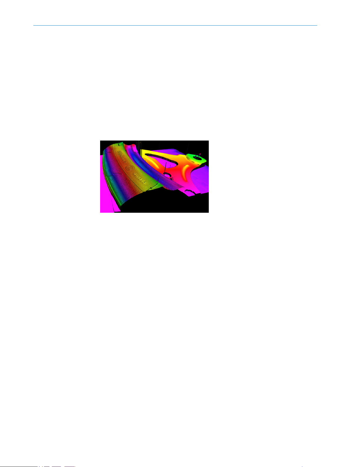
The main function of Ranger3 is to measure 3D shape of objects by the use of laser
line triangulation. This can be used for example for generating 3D images of the object,
for size rejection or volume measurement, or for finding shape defects. In the image
below, the colors represent depth.
PRODUCT DESCRIPTION 3
Figure 1: Example of 3D image
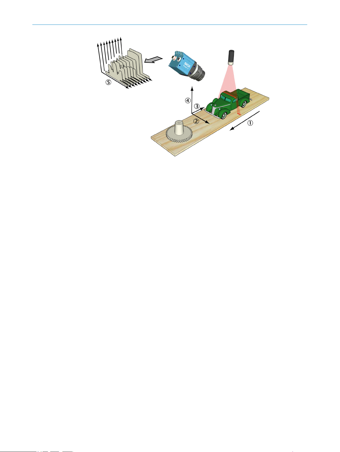
3.2 Measuring with a 3D camera
Each time the 3D camera makes a measurement, it measures along a cross-section of
the object in front of it. The result of a measurement is a profile, containing one value
for each measured point along the cross-section – for example the height of the object
along its width.
For the camera to measure an entire object, the object (or the camera and lighting)
must be moved so that the camera can make a series of measurements along the
object. The result of such a measurement is a collection of profiles, where each profile
contains the measurement of a cross-section at a certain location along the transporta‐
tion direction.
8020774/14IM/2019-07 | SICK O P ER A TI N G I NS T RU C TI O NS | Ranger3
Subject to change without notice
11
Page 12
3 PRODUCT DESCRIPTION
Figure 2: Measuring the range of a cross-section of an object
1
2
3
4
5
Transportation direction
X (width)
Y (negative transport direction)
Z (range)
Profiles
3.3
Hardware description
3.3.1 Sensor
By default, the range measurement values from the camera are not calibrated – that is:
X and Z (range) coordinates are represented by column and row positions on the
•
sensor, instead of real world positions and distances.
Y coordinates are represented for example by the sequence number of the mea‐
•
surement, or by the encoder value for when the profile was captured.
In a machine vision system, the Ranger3 camera acts as a data streamer. It is con‐
nected to a PC through a Gigabit Ethernet network. The camera sends the profiles to
the computer, and the computer runs a custom application that retrieves the profiles
and processes the measurement data in them.
Before the camera can be used in a machine vision system, the following needs to be
done:
Find the right way to mount the camera and lighting.
•
Configure (and optionally calibrate) the camera to make the proper measure‐
•
ments.
Write the application that retrieves and processes the profiles sent from the cam‐
•
era.
For more information about 3D measurements, see "Range (3D) measurement",
page 78.
12
The Ranger3 camera is based on a unique SICK CMOS sensor which has a 2D pixel
matrix, row-parallel AD-converters, and a processor architecture that enables image
processing directly on the sensor. The technology is called ROCC, which means Rapid
On-Chip Calculation. For technical details, see "Technical data", page 71.
O PE R AT I NG IN S TR U CT I ON S | Ranger3 8020774/14IM/2019-07 | SICK
Subject to change without notice
Page 13

3.4 Standards
3.4.1 GenICam™
3.4.2 GigE Vision®
PRODUCT DESCRIPTION 3
Ranger3 complies with the GenICam™ and the GigE Vision® standards.
GenICam™ is a standard that provides a generic programming interface for different kinds of cameras and devices. The standard is owned by EMVA (European Machine Vision Association) and consists of multiple modules. Ranger3 complies with the follow‐ ing modules:
GenApi Application programming interface (API) for configuring the cam‐
era.
Standard Feature Naming
Convention (SFNC)
GenTL Transport layer interface for grabbing images.
GenTL SFNC Standardized names and types for transport layer interface.
For further information, see www.emva.org/standards-technology/genicam/.
GigE Vision® is a camera interface standard that is based on the Gigabit Ethernet com‐
munication protocol. The GigE Vision® standard is owned by AIA (Automated Imaging
Association).
Standardized names and types for common device features.
For further information, see https://www.visiononline.org/vision-standards.cfm.
8020774/14IM/2019-07 | SICK O P ER A TI N G I NS T RU C TI O NS | Ranger3
Subject to change without notice
13
Page 14

4 TRANSPORT AND STORAGE
4 Transport and storage
4.1 Transport
For your own safety, please read and observe the following notes:
NOTICE
Damage to the product due to improper transport.
■
The device must be packaged for transport with protection against shock and
damp.
■
Recommendation: Use the original packaging as it provides the best protection.
■
Transport should be performed by trained specialist staff only.
■
The utmost care and attention is required at all times during unloading and trans‐
portation on company premises.
■
Note the symbols on the packaging.
■
Do not remove packaging until immediately before you start mounting.
4.2
Unpacking
■
Before unpacking, it may be necessary to equalize the temperature to protect the
device from condensation.
■
Handle the device with care and protect it from mechanical damage.
■
Remove the protective caps on the electrical connections immediately before con‐
necting the connecting cable to prevent dirt and water from entering.
4.3 Transport inspection
Immediately upon receipt in Goods-in, check the delivery for completeness and for any
damage that may have occurred in transit. In the case of transit damage that is visible
externally, proceed as follows:
■
Do not accept the delivery or only do so conditionally.
■
Note the scope of damage on the transport documents or on the transport com‐
pany's delivery note.
■
File a complaint.
NOTE
Complaints regarding defects should be filed as soon as these are detected. Damage
claims are only valid before the applicable complaint deadlines.
4.4 Storage
14
Store the device under the following conditions:
■
Recommendation: Use the original packaging.
■
Electrical connections are provided with protective caps and plugs (as they are on
delivery).
■
Do not store outdoors.
■
Store in a dry area that is protected from dust.
■
So that any residual damp can evaporate, do not package in airtight containers.
■
Do not expose to any aggressive substances.
■
Protect from sunlight.
■
Avoid mechanical shocks.
O PE R AT I NG IN S TR U CT I ON S | Ranger3 8020774/14IM/2019-07 | SICK
Subject to change without notice
Page 15

TRANSPORT AND STORAGE 4
■
Storage temperature: see "Technical data", page 71.
■
For storage periods of longer than 3 months, check the general condition of all
components and packaging on a regular basis.
8020774/14IM/2019-07 | SICK O P ER A TI N G I NS T RU C TI O NS | Ranger3
Subject to change without notice
15
Page 16
1
MOUNTING
5
5 Mounting
5.1 Mounting instructions
Observe the technical data.
•
To prevent condensation, avoid exposing the device to rapid changes in tempera‐
•
ture.
The mounting site has to be designed for the weight of the device.
•
It should be mounted so that it is exposed to as little shock and vibration as possi‐
•
ble. Optional mounting accessories are available, see "Accessories", page 75.
Protect the device from moisture, contamination, and damage.
•
A sufficient level of cooling using ambient air/convection and/or heat dissipation
•
through mechanical mounting must be ensured. Observe the permitted operating
temperature, see "Technical data", page 71.
5.2 Required parts
You need the following parts to get started with Ranger3:
Ranger3 camera.
•
PC with a network interface card (NIC) that supports Gigabit Ethernet. For informa‐
•
tion about requirements, see "Recommended network card settings", page 83.
Ethernet cable for Gigabit Ethernet, with M12 connector for the camera.
•
Power supply.
•
Line-projecting laser.
•
5.3
Mounting the camera
When measuring range, the camera is used together with a line-projecting laser that
illuminates the cross-section of the object to be measured. The camera and the laser
are mounted so that the laser illuminates the object from one direction, and the cam‐
era views the object from another direction.
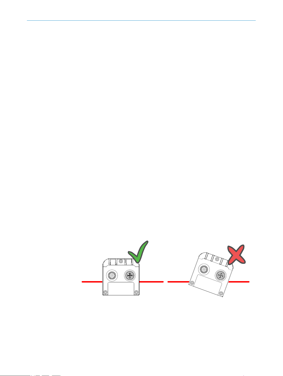
The laser line must be orthogonal to the movement direction of the object. Also mount
the camera so that the camera does not tilt sideways compared to the laser line, see
the figure below. This makes the laser line appear along the rows of the sensor in the
camera.
Figure 3: Correct (left) and incorrect (right) mounting of the camera
Laser line
1
16
For best result it is important to shield out direct sunlight and other disturbing light from
the field of view. It is recommended to use an optical band-pass filter to reduce ambi‐
ent light.
O PE R AT I NG IN S TR U CT I ON S | Ranger3 8020774/14IM/2019-07 | SICK
Subject to change without notice
Page 17

It is also important to select a lens that is suitable for the field-of-view in which the cam‐
era should measure. Select a high-quality 1" C-mount lens that gives sharp images and
low distortion, as this can be essential for achieving a successful vision application.
If needed, you can mount a protective cover that makes the camera compliant with
IP65 and IP67. For available brackets, filters, lenses, and protective cover, see "Acces‐
sories", page 75.
Exactly how to mount the camera and the laser depends on a whole number of factors.
For more information, see "Range (3D) measurement", page 78.
5.3.1 Mounting an optical filter or a Scheimpflug adapter
On delivery, there is a dummy filter in the camera to protect the sensor. When you
mount an optical filter or a Scheimpflug adapter, you remove the dummy filter so that
the sensor is unprotected. Make sure to be in a dust-free environment and pay special
attention to cleanliness.
Mounting an optical filter
1. Use the provided tool and remove the dummy filter.
2. Mount the optical filter.
NOTICE
Do not remove the dummy filter without mounting another filter.
MOUNTING 5
Using the camera without a filter can damage the sensor.
•
The distance from the lens to the image sensor is adapted to the thickness of
•
the optical filter. Without a filter, the focusing of the lens may not work prop‐
erly.
8020774/14IM/2019-07 | SICK O P ER A TI N G I NS T RU C TI O NS | Ranger3
Subject to change without notice
17
Page 18
6 ELECTRICAL INSTALLATION
6 Electrical installation
6.1 Wiring notes
NOTE
Preassembled cables can be found online at:
www.sick.com/Ranger3
•
NOTICE
Faults due to incorrect wiring.
Incorrect wiring may result in operational faults.
■
Follow the wiring notes precisely.
We recommend using shielded cables.
Connect the connecting cables in a de-energized state. Switch on the supply voltage
only after complete installation/connection of all connecting cables to the device and
control system.
6.2 Security
WARNING
Risk of injury and damage caused by electrical current!
As a result of equipotential bonding currents between the device and other grounded
devices in the system, faulty grounding of the device can give rise to the following dan‐
gers and faults:
■
Dangerous voltages are applied to the metal housings.
■
Devices will behave incorrectly or be destroyed.
■
Cable shielding will be damaged by overheating and cause cable fires.
Remedial measures
■
Only skilled electricians should be permitted to carry out work on the electrical sys‐
tem.
■
If the cable insulation is damaged, disconnect the voltage supply immediately and
have the damage repaired.
■
Ensure that the ground potential is the same at all grounding points.
■
Where local conditions do not meet the requirements for a safe earthing method,
take appropriate measures (e.g., ensuring low-impedance and current-carrying
equipotential bonding).
Only skilled electricians with appropriate training and qualifications are permitted to
perform electrical installation. Observe the following safety measures:
18
Standard safety requirements must be met when working in electrical systems.
•
Only connect and disconnect electrical connections when there is no power to the
•
system. Otherwise, the devices may be damaged.
Use only shielded cables. The shield has to be terminated at both ends of the
•
cable.
Ensure that loose cable ends are isolated.
•
Connect unused pins to GND.
•
Wire cross sections of the supply cable from the customer's power system should
•
be designed and protected in accordance with the applicable standards.
O PE R AT I NG IN S TR U CT I ON S | Ranger3 8020774/14IM/2019-07 | SICK
Subject to change without notice
Page 19

Make sure that the Power-I/O cable is protected by a separate slow-blow fuse with
•
a maximum rating of 2.0 A. This fuse must be located at the start of the supply
circuit.
The 24 V power supply must meet the requirements of SELV+LPS relating to "UL/
•
EN60950-1:2014-08", or ES1 according to "EN/UL62368", or "CAN/CSA-C22.2
No 223-M91(R2008)-Power supplies with Extra-Low-Voltage class 2 outputs", or
"UL1310 (6th Edition)-standard for class 2 power units".
All circuits connected to the device must be designed as ES1 circuits (according to
•
EN/UL62368) or as SELV (Safety Extra Low Voltage) circuits (according to EN/
UL60950).
6.3 Connecting the camera
NOTICE
Never connect any signals while the camera is powered.
•
Never connect a powered Power-I/O terminal or powered I/O signals to a camera.
•
NOTICE
Never connect a powered encoder interface unit to a camera.
•
Never connect signal levels that exceed the input specification to the encoder
•
inputs.
ELECTRICAL INSTALLATION 6
Failure to follow these rules can damage the camera.
NOTE
The function of the camera is not tested and guaranteed for Power I/O cables longer
than 10 meters.
NOTE
Use only shielded cables. The shield has to be terminated at both ends of the cable.
There are two connectors on the back of the camera: Gigabit Ethernet (GigE) and Power
I/O (see figure 4, page 20).
To prepare the camera for operation, do as follows:
1. Remove the protection caps that cover the connections for Gigabit Ethernet (GigE)
and Power I/O.
2. Connect the Ethernet cable to the GigE connector on the camera. Connect the
other end of the Ethernet cable to the Network Interface Card (NIC) in the PC.
3. Connect the connecting module to the Power I/O connector on the camera.
4. Connect the unpowered power supply to the connecting module.
5. Connect the laser to its power supply.
6. Switch on the power to the system.
For more information on how to connect I/O signals to the camera, see the following
sections:
Electrical connections
•
Connecting encoders
•
6.4
8020774/14IM/2019-07 | SICK O P ER A TI N G I NS T RU C TI O NS | Ranger3
Subject to change without notice
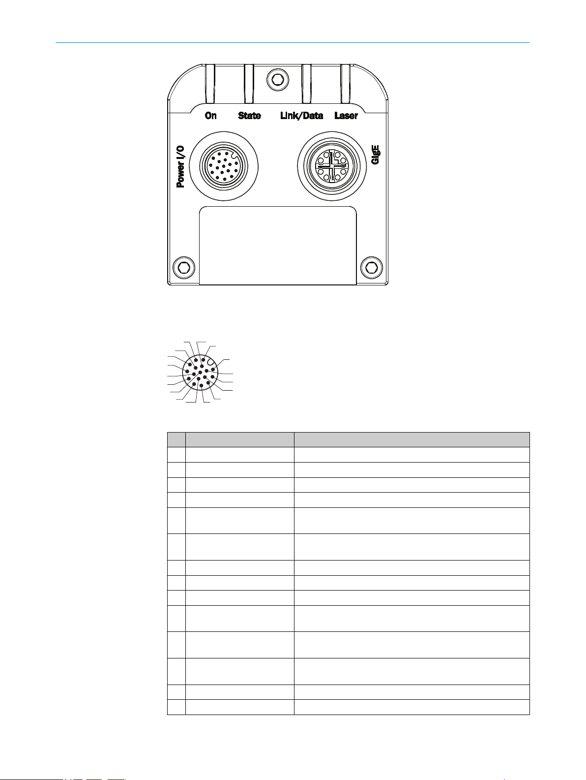
Electrical connections
There are two connectors and four LEDs on the back plate of Ranger3.
19
Page 20
3
1
7
2
6
5
4
8
13
14
17
15
9
10
12
16
11
6 ELECTRICAL INSTALLATION
Figure 4: Back plate of the Ranger3 device
Power I/O connector
Table 2: Power I/O connector, 17 pin
Pin Signal Description
1 GND Power/signal ground
2 POWER SUPPLY Power supply DC 24 V +/-20%
3 - Not connected
4 - Not connected
5 ENC IN A+ Encoder Input A+
Default: RS422 TTL
6 ENC IN A- Encoder Input A-
Default: RS422 TTL
7 - Reserved
8 - Reserved
9 - Not connected
10 FRAME TRIGGER IN 24 V Frame trigger input or configurable 24 V Input/Output
Default: Frame trigger input
11 ENC IN B+ Encoder Input B+
Default: RS422 TTL
12 ENC IN B- Encoder Input B-
Default: RS422 TTL
13 LASER STROBE OUT1
20
O PE R AT I NG IN S TR U CT I ON S | Ranger3 8020774/14IM/2019-07 | SICK
14 LASER STROBE OUT2
1
5 V trigger output for Laser or Strobe
1
5 V trigger output for Laser or Strobe
Subject to change without notice
Page 21
1
7
2
6
54
3
8
ELECTRICAL INSTALLATION 6
Pin Signal Description
15 LINE TRIGGER IN
16 I/O 3
17 I/O 4
1
1
1
Not connected for article number 1083672
Notes
Make sure, that at all times, the voltage at the I/O pins is lower or equal to the
•
voltage at the supply pins. If not, you risk to power on the camera through the I/O
pins although it is turned off (V supply = 0 V), which is strictly forbidden.
When using a single-channel encoder, connect it to Encoder Input A+/A- (pin 5
•
and 6)
Table 3: Signal levels for Power I/O connector
Signal Pins Low High Remark
24 V inputs 10, 15, 16,170... 9 V 12.5... V_Supply Pulldown: 22.5
TTL 5, 6, 11, 12 0... +0.8 V +2 V... V_Supply RC-termination,
24 V outputs 16, 17 Output type:
5 V outputs 13, 14 Output type:
1
24 V Line trigger input or configurable 24 V Input/Output
Default: Line trigger input
Encoder reset input or configurable 24 V Input/Output
Default: Encoder reset
Configurable 24 V Input/Output
kΩ
112 Ω / 340 pF
Push-pull.
Max output cur‐
rent: 100 mA
Push-pull.
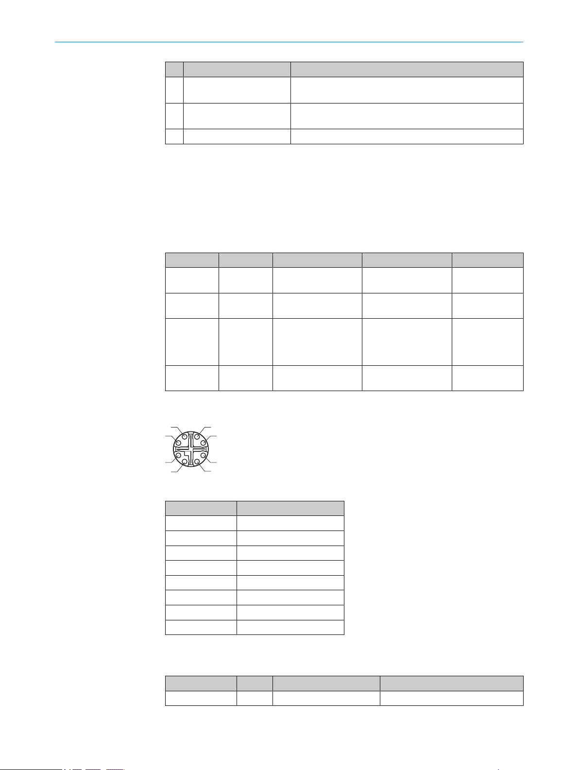
GigE connector
Table 4: GigE connector, 8 pin
Pin Signal
1 GETH L1+
2 GETH L1-
3 GETH L2+
4 GETH L2-
5 GETH L4+
6 GETH L4-
7 GETH L3-
8 GETH L3+
LED definitions
Table 5: LED definitions
Indicator LED Color Function
On
Green Power ON
O
8020774/14IM/2019-07 | SICK O P ER A TI N G I NS T RU C TI O NS | Ranger3
Subject to change without notice
21
Page 22

6 ELECTRICAL INSTALLATION
Indicator LED Color Function
State
Link/Data Off No Ethernet connection
Laser
O= illuminated, Ö= flashing
Yellow Booting (slow flashing) or firmware
Ö
upgrade (fast flashing)
Yellow Idle (or acquiring single frames)
O
Green Continuous acquisition
O
Red Thermal warning (risk of overheating)
Ö
Red The device is in rescue mode, due to
O
software problems or overheating.
For more information, see "Rescue
mode", page 68.
Green Connection established, 1 gigabit/s
O
Green Ethernet frames are being transmit‐
Ö
ted or received
Green Laser output active (Not imple‐
O
mented)
22
O PE R AT I NG IN S TR U CT I ON S | Ranger3 8020774/14IM/2019-07 | SICK
Subject to change without notice
Page 23

7 Configuration
7.1 Software installation
7.1.1 System recommendations
The PC requirements for the vision system will depend on your application, but as a
general guideline the following is recommended for minimal operation:
Windows 7 or Windows 10, 64 bit.
•
Gigabit Ethernet adapter that supports Jumbo Frames and is dedicated for camera
•
communication, see "Recommended network card settings", page 83.
7.1.2 Network preparations
Due to the large amount of data that the camera delivers per second, it is required to
connect it to the PC using a dedicated Gigabit Ethernet network, without other interfer‐
ing traffic. If the PC must be connected to other equipment, for example network print‐
ers, the PC should be equipped with (at least) two network interface cards (NIC).
Multiple cameras can be connected using a NIC with multiple ports, or multiple NICs. To
connect multiple cameras to a single NIC limits the maximum speed of the cameras.
For best performance, connect each camera to a separate NIC.
CONFIGURATION 7
For recommended network settings, see "Recommended network card settings",
page 83.
7.1.3 Installing PC software
The latest version of the Ranger3 software deployment kit (SDK) can be downloaded
from the SICK Support Portal, supportportal.sick.com.
1. Log in to the SICK Support Portal.
2. Navigate to the Ranger3 product page.
3. Under Releases, click the link corresponding to the latest version of the Ranger3
SDK.
4. Download the SDK zip file.
5. Unzip the SDK and follow the instructions in the README.txt file.
The SDK contains the Ranger3 Studio software application, which is used for the con‐
figuration and operation procedures described in this manual. To start the application,
open the Ranger3 Studio sub-folder and click the Ranger3 Studio.exe file.
7.2 Concepts
The GenICam™ standard uses "feature" as a common word for parameters, com‐
mands, and selectors.
7.2.1 Selectors
In a GenICam™ device, such as Ranger3, selectors are used to access parameters that
are organized in arrays. That is, the selector acts as the index for the affected parame‐
ters. Changing the selector does not change any parameter. A parameter indexed by a
selector is notated ParameterA[SelectorX].
Example: The parameter Width[RegionSelector] sets the width of a region. The value of
RegionSelector decides which region that is manipulated. This means that Width[Region1]
is the width of the region named Region1.
8020774/14IM/2019-07 | SICK O P ER A TI N G I NS T RU C TI O NS | Ranger3
Subject to change without notice
23
Page 24

7 CONFIGURATION
7.3 Configuring Ranger3
Before the camera can be used in a machine vision system, it has to be configured.
This is usually done by setting up the camera in a production-like environment and eval‐
uate different parameter settings until the result is satisfactory, see "Editing parame‐
ters", page 55.
The following can be specified when configuring the Ranger3:
Regions Where on the sensor to measure and dimensions of the
Exposure time For how long to expose the sensor.
Triggering settings When to make a measurement.
Component-specific settings How to process the measurement result before sending
All this is specified by setting parameters in Ranger3. The parameters, as well as the
selectors and commands, are organized in hierarchical groups. Each group belongs to
one of the following categories1):
DeviceControl Contains the features related to the control and informa‐
ImageFormatControl Contains the features related to the format of the
AcquisitionControl Contains the features related to image acquisition,
DigitalIOControl Contains the digital input and output control features.
TimerControl Contains the Timer control features.
EncoderControl Contains the features related to the usage of quadrature
EventControl Contains the features related to the generation of Event
FileAccessControl Contains the File Access control features.
Scan3dControl Contains the features related to the control of the 3D
ChunkDataControl Contains the features related to the Chunk Data Control.
TestControl Contains the features related to the control of the test
TransportLayerControl Contains the features related to the Transport Layer Con‐
3D output frame.
it to the PC.
tion of the device.
acquired and transmitted images.
including trigger control.
encoders.
notifications by the device.
scan features.
features.
trol (Gigabit Ethernet).
7.4 Regions
There are two types of regions:
It is possible to define multiple regions for both 2D and 3D. In different device versions
different number of sensor and extraction regions are possible. Typically, you use at
least one sensor region for imaging and one sensor and extraction region pair for 3D
profiling purposes. You use the selector RegionSelector to select the region you want to
view and manipulate parameters from, see "Selectors", page 23.
1)
According to GenICam™ SFNC version 2.4.
24
O PE R AT I NG IN S TR U CT I ON S | Ranger3 8020774/14IM/2019-07 | SICK
Sensor regions
RegionSelector = Region0, Region1
Extraction regions
RegionSelector = Scan3dExtraction1
Defines the sensor image dimensions and
readout conditions, see "Sensor regions",
page 25.
Defines the processing and formatting condi‐
tions of the generated 3D linescan output
data, see "Extraction regions", page 25.
Subject to change without notice
Page 25
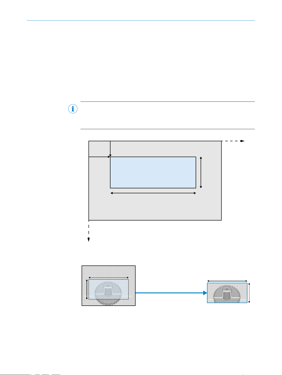
7.4.1 Sensor regions
OffsetY
OffsetX
Width
Height
Y
X
(0, 0)
Width[Region0]
Height[Region0]
Height[Region0]
Width[Region0]
CONFIGURATION 7
Data from the sensor is used as standard 2D image output and as input to the calcula‐
tion of the 3D data. The sensor region that is used when viewing the 2D intensity image
(Region0) and the sensor region used as input to the processing module (Region1) are
defined independently of each other.
The sensor region defines which area of the sensor to use. Using a smaller region on
the sensor enables measurements at a higher rate. The region is specified by the para‐
meters OffsetX, OffsetY, Width, and Height as shown in the figure below. The resulting
image generated by the device will have Width times Height pixels. OffsetX and OffsetY are
given with respect to the upper left corner of the image area. This corner has the coordi‐
nates (0,0) in the imager (x, y) coordinate system. All measures are given in pixels.
NOTE
In GenICamTM devices, such as Ranger3, imager coordinates are defined as (x,y). In
more general terms, image sensor coordinates are usually defined as (u,v), see "Sensor
coordinate system", page 82.
Figure 5: Image area and 2D region
The 2D intensity image is based on the sensor region Region0, see the figure below.
Figure 6: 2D image
7.4.2 Extraction regions
The extraction region (Scan3dExtraction1) uses input from a sensor region (Region1).
Together with a processing module, the extraction region defines the processing and
8020774/14IM/2019-07 | SICK O P ER A TI N G I NS T RU C TI O NS | Ranger3
Subject to change without notice
formatting conditions of the generated 3D linescan output data.
25
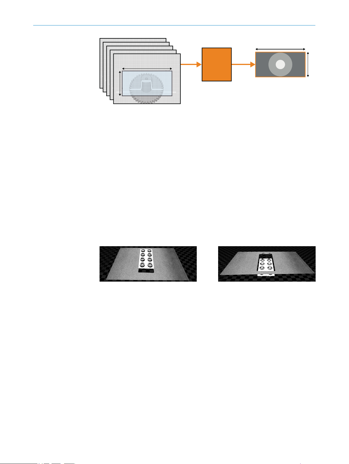
Page 26
3D extraction
processing
module
1
Height[Scan3dExtraction1]
Width[Scan3dExtraction1]
Height[Region1]
Width[Region1]
7 CONFIGURATION
Figure 7: 3D image
3D extraction processing module
1
In Linescan 3D mode, the Height and Width parameters of the region Scan3dExtraction1
define the dimensions of the 3D extraction output frame. Typically, the Width parameter
of an extraction region is locked to the same value as the Width of the source region on
the sensor.
To get a 3D image, several 2D images are required. Each 2D image corresponds to one
profile, see "Measuring with a 3D camera", page 11. The 2D sensor images are trans‐
formed into lines in the 3D extraction output frame. Each line in the frame corresponds
to one 2D image. This means that the Height value of the frame tells how many 2D
images that are used to generate the resulting 3D image. The 3D image has Width times
Height pixels.
The RangeAxis parameter defines how the lines in the 3D extraction output frame are
visualized. The parameter is set to Reversed by default, which means that high values in
the range data correspond to low values on the imager Y axis. If the parameter is set to
Standard, high range values correspond to high values on the imager Y axis and the visu‐
alized 3D object appears upside down. See figure 8 and figure 9 for examples.
Figure 8: RangeAxis set to Reversed
7.4.3 Device scan type
The camera can be configured to output either the raw data from the image sensor or
the 3D profile data. In the user interface, you select Image to see the raw sensor data as
a 2D image or Data collection to get the 3D profile data, see "Workflow steps", page 48.
The camera uses the parameter DeviceScanType to control if 2D images or 3D profiles
are acquired. This parameter is set when you select Image or Data collection. Setting the
DeviceScanType automatically sets the relevant features for the correct mode, as
described below.
Image
Figure 9: RangeAxis set to Standard
26
O PE R AT I NG IN S TR U CT I ON S | Ranger3 8020774/14IM/2019-07 | SICK
DeviceScanType is set to Areascan.
The following settings are done automatically:
RegionMode[Region0] = On
RegionMode[Region1] = Off
RegionMode[Scan3dExtraction] = Off
Subject to change without notice
Page 27

Data collection
DeviceScanType is set to Linescan3d.
The following settings are done automatically:
RegionMode[Region0] = Off
RegionMode[Region1] = On
RegionMode[Scan3dExtraction] = On
7.4.4 Maximum buffer size
The maximum size for an image buffer to be sent from Ranger3 to the host PC is
around 40 MB, and the maximum supported buffer height is 16383 profiles. The limit
is due to the limited GigE Vision retransmission buffer memory in the device.
The maximum buffer height (Height[Scan3dExtraction1]) depends on the data format, the
region width (Width[Region1]) and the number of enabled components (e.g. reflectance,
see "Reflectance data", page 30). For example: With default settings, the maximum
Height is about 11000 profiles. When reflectance is enabled, the maximum Height
decreases to about 7000 profiles.
If the buffer size is maximized, the camera may block user actions that further increase
the size. Examles of such actions are:
CONFIGURATION 7
Enabling another component, such as reflectance
•
Increasing the bit-depth of a pixel format
•
Increasing the region width
•
The user must decrease the buffer size to make the blocked actions available again.
This is done by changing the data format, decreasing the region width or decreasing the
number of enabled components.
7.5 Exposure time and measurement speed
Once the height of the sensor region is set, there are two other parameters that affect
the line rate of the camera:
AcquisitionLineRate The rate at which the lines in a frame are captured (Hz). Only
applicable when the camera is in free-running mode.
ExposureTime The time (μs) during which the sensor region is exposed.
The exposure time and the line rate are inter-dependent. The maximum exposure time
cannot be longer than the time between two profiles, minus about three microseconds
that are needed for readout and reset.
NOTE
The maximum exposure time and the maximum line rate are stored as floating point
values and rounding-off effects may make it impossible to set the exact value returned
by the GUI. The maximum deviation is 0.01 μs for the exposure time and 0.01 Hz for
the line rate.
7.6 Laser strobe output signals
The camera has two laser strobe output signals, LASER STROBE OUT1 and LASER STROBE
OUT2, see "Electrical connections", page 19. These signals are individually controlled
and can be used to control two separate lasers. You can use the signal to turn the laser
on only when it is needed, for example when two separate cameras and lasers are used
at the same time.
8020774/14IM/2019-07 | SICK O P ER A TI N G I NS T RU C TI O NS | Ranger3
Subject to change without notice
27
Page 28

TimerDuration
LineStart
LaserStrobeOut
SensorTrigger
t2
ExposureTime
t1
t0
Intensity 1
ROI start 4
ROI end 3
Sensor row 2
7 CONFIGURATION
In the figure below, the laser is turned on slightly before the sensor exposure time
starts. The reason for this is to allow turn-on time. When the exposure is finished, the
laser is turned off.
The LineStart trigger signal from the encoder is used as a reference. The TimerDelay para‐
meter sets the delay time (t1-t0) from the LineStart signal (t0) until the laser is turned
on. The TimerDuration parameter defines for how long the laser is on. When TriggerSelector
is set to ExposureStart, the TriggerDelay parameter sets the delay time (t2-t0) from the
LineStart signal until the exposure starts.
The maximum time (in seconds) between two LineStart signals is 1/(maximum Acquisi‐
tionLineRate). The higher the line rate, the shorter the cycle time.
Figure 10: Laser is on only during exposure
7.7
3D profiling
7.7.1 Laser impact position on the sensor
The basic function of the 3D measurements is to compute the impact position of the
laser line for all columns of the selected region of interest (ROI). The light intensity dis‐
tribution from the laser line along a sensor column across the laser line can be
described as in the figure below.
Figure 11: The impact position of the laser in one column
Intensity
1
Sensor row
2
ROI end
3
28
O PE R AT I NG IN S TR U CT I ON S | Ranger3 8020774/14IM/2019-07 | SICK
Subject to change without notice
Page 29

ROI start
Intensity 1
ROI start 4 ROI end 3
Sensor row 2
DetectionThreshold
6
6
5
4
The laser line will produce a distinct light peak distributed over a number of pixels along
the sensor column. The center of this peak will be defined as the impact position of the
laser line on that sensor column, which is the range value.
7.7.2 Measurement method
The default algorithm in Ranger3 is called Hi3D. It measures the impact position using
a high-resolution peak fitting algorithm based on the pixels in a window around the
extracted intensity peak position. The size of the window is set by the WAMSize parame‐
ter.
This method measures range with a resolution of 1/16th pixel.
7.7.3 Detection threshold
The parameter DetectionThreshold defines the minimum reflectance signal that can be
detected as a peak position. Ideally, this parameter is set to a value that is higher than
the amplitude of the noise, but still low enough to detect the laser signal, see the figure
below. If DetectionThreshold is too low, noise will be registered as laser peaks. This will
result in bad image quality. If DetectionThreshold is too high, not all laser peaks will be
registered. This will result in an image where some parts are missing.
CONFIGURATION 7
Figure 12: Analog signal with noise
Intensity
1
Sensor row
2
ROI end
3
ROI start
4
Detected peak
5
Not detected peaks
6
7.8 3D data formats
The 3D data is delivered with 4 subpixel bits resolution. The data can be represented
with 12 or 16 bits. 12 bits allows a higher scan rate given the limitations of the Gigabit
Ethernet link. For 12 bits a maximum region height of 256 rows can be represented.
Any data outside of this is clipped/limited to the maximum value.
The pixel value 0 is dedicated to represent missing data, i.e. that no valid peak was
8020774/14IM/2019-07 | SICK O P ER A TI N G I NS T RU C TI O NS | Ranger3
Subject to change without notice
found. This means that the lowest value possible is 0.0625 (1/16th).
The coordinate system of the data is independent of the region position. That is, the
value 0.0625 always represents a position 1/16th of a pixel from the start of the
region. If a buffer is saved to file, the offsetY information is stored in the XML descrip‐
tion so that the actual position on the sensor can be calculated.
29
Page 30

Light intensity 2
Pixel value 1
5
6
4
Maximum
pixel value
3
7 CONFIGURATION
According to the GenICam™ and GigE Vision® standards, 3D data should be repre‐
sented using coordinate pixel formats. For Ranger3, these formats are Coord3d_C12p
and Coord3d_16. To allow a receiver that is not compatible with those new formats, the
binary compatible grayscale formats mono_12p and mono_16 can be used.
7.9 Reflectance data
The reflectance values along the laser line can be collected in parallel to the 3D data.
The reflectance values are saved as an 8-bit grayscale image, with one value corre‐
sponding to each point in the range dataset.
For information about how to enable reflectance measurements, see "Enabling
reflectance measurements", page 58.
7.10 High dynamic range (HDR) imaging
Ranger3 supports high dynamic range (HDR) imaging, which increases the sensor's
ability to adequately reproduce both bright and dark areas in a scene. HDR is suitable
for improving the localization of the laser line when acquiring images containing both
dark and bright materials, such as bright objects towards a dark background or dark
objects with bright prints.
Figure 13: Acquisition of
profiles
Figure 14: Resulting profile,
linear (non-HDR) mode
Figure 15: Resulting profile,
HDR mode
Ranger3 uses an HDR principle called multiple-slope with one knee-point, which means
that the normal linear relationship between the received light and the resulting pixel
value (reflectance) is broken into two linear segments. The result is a compressed lightto-pixel value characteristic for high light intensities, according to figure 16.
Figure 16: HDR multiple-slope principle
Pixel value
1
Light intensity
2
Maximum pixel value
3
Linear (non-HDR) mode
4
HDR mode
5
Knee-point
6
30
O PE R AT I NG IN S TR U CT I ON S | Ranger3 8020774/14IM/2019-07 | SICK
Subject to change without notice
Page 31

0
0 500 1000 1500 2000 2500 3000 3500
Light intensity 2
Pixel value 1
50
100
150
200
250
3
4
5 6
CONFIGURATION 7
The knee-point position and the slope after the knee-point are controllable by the Multi‐
SlopeMode parameter in the camera. There are three pre-defined parameter settings
(soft, medium and aggressive) which correspond to different amounts of compression.
These settings result in a dynamic range increase of approximately 2, 6 and 15, respec‐
tively. See figure 17.
Figure 17: HDR settings for Ranger3
Pixel value
1
Light intensity
2
Linear (non-HDR) mode
3
Soft pre-set
4
Medium pre-set
5
Aggressive pre-set
6
In HDR mode, the sensor readout must be finished before a new exposure can start.
The minimum cycle time is the sum of the exposure time and the readout time. In linear
mode, the sensor readout and a new exposure can be done in parallel.
For example: If the readout time is 33 μs and the exposure time is 30 μ, the total cycle
time is 33 μs for linear mode and 63 μs for HDR.
For information about how to enable HDR imaging for Ranger3, see "Enabling HDR
imaging", page 59.
7.11
Triggering
Triggering is used to control the initiation and rate of data acquisition. Different trigger‐
ing concepts and modes are presented below.
See "Setting triggering parameters", page 60 for information about how to activate
triggering and set the parameters in the user interface.
7.11.1 3D triggering concepts
Different application types require different triggering concepts. Below is a table of the
most common triggering situations.
Continuous flow No photoelectric switch is used.
Profiles are sent continuously to the PC, typically
arranged in frames of at least a few hundred pro‐
files.
Examples: Crushed stone, grain, sawdust.
8020774/14IM/2019-07 | SICK O P ER A TI N G I NS T RU C TI O NS | Ranger3
Subject to change without notice
31
Page 32

7 CONFIGURATION
7.11.2 Triggering modes
There are different ways to trigger the camera to acquire frames and profiles. You can
use an external signal to trigger each frame or each single profile. The camera can also
be configured to acquire frames or profiles with regular time intervals, without an exter‐
nal trigger signal.
Continuous flow
of discrete
objects
Shorter objects
of equal length
Longer objects of
variable size
No photoelectric switch is used.
Profiles are sent continuously to the PC, typically
arranged in frames of at least a few hundred lines.
The resulting image buffers in the PC can be ana‐
lyzed in a rolling buffer fashion, ensuring that all
objects are analyzed completely.
Example: Cookies.
A photoelectric switch is used.
One image per object.
Examples: Bottles, automotive parts, mobile
phones.
A photoelectric switch is used.
Acquire profiles as long as the object remains in
front of the camera.
Several sub-images can be stitched together in the
PC.
Examples: Logs, fish, postal packages.
Note that when the camera acquires 2D images, a frame is the same thing as a com‐
plete 2D image. When the camera acquires 3D images, each frame is a set of profiles.
This means that the acquisition of profiles and the Line triggering concept are only
applicable for 3D images, while the 2D image triggering concept is only relevant for 2D
images.
Frame triggering The camera will acquire frames based on an external input signal,
for example from a photoelectric switch.
The acquisition of profiles can either be free-running or triggered
by an input signal, as described in the sections Free-running and
Line triggering below.
Line triggering The camera will acquire each profile based on an external input
signal. There are two possibilities:
Connect an external input signal to the line trigger input of the
•
device.
Use an encoder for line triggering. In that case, pulses are
•
received on the encoder inputs. The distance between two
profiles is determined by the number of pulses received.
Triggering each profile from an encoder will keep the object pro‐
portions if the object motion, tracked by the encoder, changes.
Four-phase encoders also allow tracking different motion pat‐
terns, see "Triggering using an encoder", page 33. The motion
pattern is defined by the EncoderOutputMode parameter.
When you use the line trigger input, each pulse on the line trigger
input triggers one profile. Profiles are triggered when the object is
moving either backward or forward. The EncoderOutputMode para‐
meter is not used.
32
O PE R AT I NG IN S TR U CT I ON S | Ranger3 8020774/14IM/2019-07 | SICK
Subject to change without notice
Page 33

Free-running The camera will acquire 2D images (in Areascan mode) or profiles
1 3
2
2D image triggering The camera will acquire 2D images based on external pulses on
7.11.3 Triggering using an encoder
When you use an encoder for triggering, the camera counts the number of pulses
received on the encoder inputs using an internal counter. When the specified number
of pulses have been received, a profile or a 2D image is triggered and the camera
resets the triggering condition counter.
CONFIGURATION 7
(in Linescan3D mode) with a regular time interval. In Areascan
mode the time interval is controlled by the AcquisitionFrameRate
parameter and in Linescan3D mode by the AcquisitionLineRate
parameter.
When the acquisition of profiles is free-running, the distance
between two profiles varies if the speed of the object is not con‐
stant. This may distort the image. To avoid distortion, you can use
an encoder and record the counter value for each profile. This
information makes it possible to calculate a correct image.
the encoder inputs.
The use of a four-phase encoder allows tracking of different
motion patterns. The principles for motion tracking during 2D
image triggering are the same as for line triggering, see "Trigger‐
ing using an encoder", page 33.
Four-phase (dual-channel) encoder
The default definition of a pulse is a full four-phase cycle on the encoder inputs. This
gives a pulse counter that is robust to jitter and noise on the inputs.
A four-phase encoder can handle movements in both directions (forward and back‐
ward). The camera can be configured to react to the pulses in different ways, resulting
in different ways to trigger profiles. The different line triggering modes are illustrated
below.
Mode Parameter Description
Position EncoderOut‐
putMode =
PositionUp
or Position‐
Down
Direction EncoderOut‐
putMode =
DirectionUp
or Direction‐
Down
Motion EncoderOut‐
putMode =
Motion
Table 6: Triggering modes
The encoder triggers a profile for each object position.
If the object has moved backward, no profiles are triggered until
the object has moved (at least) an equal distance forward.
PositionUp: "Forward" is defined as the positive direction.
PositionDown: "Forward" is defined as the negative direction.
The encoder triggers profiles when the object is moving forward.
If the object has moved backward, new profiles will be triggered as
soon as the object moves forward again.
DirectionUp: "Forward" is defined as the positive direction.
DirectionDown: "Forward" is defined as the negative direction.
The encoder triggers profiles when the object is moving either
backward or forward.
Position
Direction
8020774/14IM/2019-07 | SICK O P ER A TI N G I NS T RU C TI O NS | Ranger3
Subject to change without notice
33
Page 34

0 V
24 V
Height Height Height
Frame
trigger
signal
1
Profile acquisition
(level sensitive) 2
3
4
5
7 CONFIGURATION
Motion
Single-channel encoder
A single-channel encoder uses only one encoder channel. The input from the encoder
to the camera is a differential signal, and a profile is triggered each time the signal
goes high.
When a single-channel encoder is used, the camera cannot differentiate between for‐
ward and backward movement. The single-channel encoder mode (EncoderMode = Sin‐
gleChannel) is therefore only visible and selecteable when the EncoderOutputMode (see
table 6) is set to Motion.
7.11.4 Frame triggering
The Frame trigger input is used to trigger the camera to start to acquire profiles when
the object passes a photoelectric switch. If the same photoelectric switch is connected
to several cameras then synchronization at the microsecond level can be achieved.
When using the Frame trigger input, the Height[Scan3dExtraction1] parameter specifies
the number of profiles that the camera acquires after the Frame trigger signal goes
high. After the specified number of profiles, the camera will either idle or continue to
acquire another series of profiles, depending on the state of the Frame trigger signal
and the settings of the acquisition control parameters. See the table and the figure
below.
1 Moving forward 2 Moving backward 3 Moving forward again
Parameter settings
TriggerSelector = FrameStart
TriggerMode[TriggerSelector] = Off
TriggerSelector = FrameStart
TriggerMode[TriggerSelector] = On
The camera acquires profiles continuously.
•
The acquisition of a new series of profiles (that is, captur‐
•
ing of a new frame) starts each time the Frame trigger
input has a high level as input.
Multiple Frame trigger signals are ignored until all profiles
•
(as specified by Height[Scan3dExtraction1]) have been
acquired.
Note that for the very first profile the camera requires not
•
only a high level but also a rising edge.
The system adapts the buffer height for the frame grabber and the camera to the
Height[Scan3dExtraction1] parameter to keep the image synchronized and receive a full
image after the image capture is completed. To avoid unnecessary CPU load, set the
Height[Scan3dExtraction1] parameter to no less than 100 pixels.
34
Figure 18: Timing diagram for Frame trigger signal
Frame trigger signal
1
Profile acquisition (level sensitive)
2
O PE R AT I NG IN S TR U CT I ON S | Ranger3 8020774/14IM/2019-07 | SICK
Subject to change without notice
Page 35

7.12 Chunk data
CONFIGURATION 7
Frame trigger signal rising edge. Acquisition of profiles starts.
3
Frame trigger signal rising edge. Ignored.
4
Acquisition complete. Interpretation of Frame trigger signal.
5
Chunk data are tagged blocks of data, that are sent together with the image data. In
Ranger3, chunk data are used to add encoder data to the image data. Each buffer con‐
tains, in addition to the image data, a chunk of meta data. The following meta data are
available for each buffer:
The value of the encoder counter for each line in the buffer.
•
The timestamp for each line in the buffer.
•
The height of the buffer.
•
The width of the buffer.
•
7.13
Features
The features that are used for Ranger3 are listed in the following sections (see "Con‐
cepts", page 23 for a definition of a feature). Most of the features comply with GenI‐
Cam™ SFNC. There are also some custom features that are described in separate
tables.
The "Type" column defines the data type for a feature. GenICam defines a number of
interface classes for SFNC features, where each interface class corresponds to a data
type. For example, the interface class "IBoolean" corresponds to the data type
"boolean".
The "Visibility" column defines which user that sees a feature in the parameter editor,
see "Parameter editor", page 47. Note that the visibility level of some standard fea‐
tures has been adjusted compared to the recommended setting.
The "Access" column defines if the feature is readable ("R"), writeable ("W"), or both
("RW"). "R(W)" means that for some selector values the feature is both read- and write‐
able, but for other selector values it is just readable. In some cases, the read- and write‐
ability of a certain parameter depends on the model and version of the device.
For further information, including detailed descriptions of the standard parameters, see
www.emva.org/standards-technology/genicam/.
NOTE
There are parameter dependencies both within and between the feature groups, which
means that changing the value of one parameter might also change the value of others.
Examples:
The maximum AcquisitionLineRate value depends on the Height value (a larger num‐
•
ber of rows gives a lower maximum speed).
The maximum ExposureTime value depends on the AcquisitionLineRate value (see
•
"Exposure time and measurement speed", page 27)
8020774/14IM/2019-07 | SICK O P ER A TI N G I NS T RU C TI O NS | Ranger3
Subject to change without notice
35
Page 36

7 CONFIGURATION
7.13.1 Device control
Table 7: Device control standard SFNC selector
Selector Type Description Visibility
DeviceTemperatureSelector enum Selects the location within the device, where the tem‐
perature will be measured.
Values:
Sensor, SensorBoard, MainBoard, ZpmSoc, Zpm1,
Zpm2, Zpm3, Zpm4, Filter
Table 8: Device control standard SFNC parameters
Parameter Type Description Visibility Access
DeviceScanType enum Scan type of the sensor of the device.
Ranger3 uses this parameter to control if 2D images
(Areascan) or 3D profiles (Linescan3D) are acquired.
Changing the DeviceScanType automatically sets the rele‐
vant device features for the selected mode. see "Device
scan type", page 26 for details.
Values:
Areascan
Linescan3d
DeviceVendorName string Name of the manufacturer of the device. Expert R
DeviceModelName string Model of the device. Expert R
DeviceVersion string Version of the device.
Used to note hardware version.
DeviceFirmwareVersion string Version of the firmware in the device. Expert R
DeviceManufacturerInfo string Manufacturer information about the device. Expert R
DeviceSerialNumber string Device's serial number. Expert R
DeviceUserID string User-programmable device identifier. Beginner RW
DeviceSFNCVersionMajor int Major version of the Standard Features Naming Con‐
vention that was used to create the device's GenICam
XML.
DeviceSFNCVersionMinor int Minor version of the Standard Features Naming Con‐
vention that was used to create the device's GenICam
XML.
DeviceSFNCVersionSubMinor int Sub minor version of Standard Features Naming Con‐
vention that was used to create the device's GenICam
XML.
DeviceTLType enum Transport Layer type of the device.
Values:
GigEVision
DeviceTLVersionMajor int Major version of the Transport Layer of the device. Expert R
DeviceTLVersionMinor int Minor version of the Transport Layer of the device. Expert R
DeviceTLVersionSubMinor int Sub minor version of the Transport Layer of the device. Expert R
DeviceLinkThroughputLimit int Limits the maximum bandwidth of the data that will be
streamed out by the device on the selected Link.
DeviceLinkHeartbeatTimeout int Controls the current heartbeat timeout of the specific
link.
A high link heartbeat timeout can be useful when
debugging PC application code. The time (in ms) is the
timeout before the device returns the Access Status to
"Open" and disconnects from the current host.
Beginner
Expert R(W)
Expert R
Expert R
Expert R
Expert R
Expert R
Guru RW
Guru RW
36
O PE R AT I NG IN S TR U CT I ON S | Ranger3 8020774/14IM/2019-07 | SICK
Subject to change without notice
Page 37

CONFIGURATION 7
Parameter Type Description Visibility Access
DeviceRegistersValid bool Returns if the current register set is valid and consis‐
tent.
Updated after the DeviceRegistersStreamingEnd com‐
mand.
DeviceTemperature[DeviceTem‐
float Device temperature in degrees Celsius (C). Beginner R
peratureSelector]
Table 9: Device control custom parameters
Parameter Type Description Visibility Access
DeviceRegistersStreamingActive bool True if a registers streaming session is active. Guru R
DeviceTemperatureMin int The minimum temperature ever in degrees Celsius (C)
measured at the location selected by DeviceTempera‐
tureSelector.
DeviceTemperatureMax int The maximum temperature ever in degrees Celsius (C)
measured at the location selected by DeviceTempera‐
tureSelector.
DeviceCurrentBootPath enum The booted software path, i.e., bootloader, kernel, appli‐
cation etc. Primary is the normal path and Secondary is
used for rescue purposes if the primary path fails.
Values:
Primary
Secondary
DeviceNextBootPath enum The boot path that will be used after the next soft
reset1. This is normally set to secondary to boot the res‐
cue version of the system if an unexpected reset
occurs.
Values:
Unknown
Primary
Secondary
DeviceBootCount int Accumulated number of times the device has been
booted.
DeviceOperationTime int Accumulated operation time of the device, in seconds. Beginner RO
1
A soft reset is an unwanted re-boot of the device.
Table 10: Device control standard SFNC commands
Command Description Visibility Access
DeviceReset Resets the device to its power up state. Guru RW
DeviceRegistersStreamingStart Prepare the device for registers streaming without
checking for consistency.
DeviceRegistersStreaming is used when loading and
saving a device's configuration to/from file on the host.
DeviceRegistersStreamingEnd Announce the end of registers streaming.
After this command DeviceRegistersValid is updated to
reflect the status of the device settings.
Expert R
Beginner RO
Beginner RO
Expert R
Guru R
Beginner RO
Guru W
Guru W
8020774/14IM/2019-07 | SICK O P ER A TI N G I NS T RU C TI O NS | Ranger3
Subject to change without notice
37
Page 38

7 CONFIGURATION
7.13.2 Image format control
Table 11: Image format control standard SFNC selectors
Selector Type Description Visibility
RegionSelector enum Selects the Region of interest to control.
Values:
Region0
Region1
Scan3dExtraction1
ComponentSelector enum Selects a component to activate/deactivate its data
streaming.
Values:
Intensity, Range, Reflectance, Scatter
Table 12: Image format control standard SFNC parameters
Parameter Type Description Visibility Access
ExposureTime[RegionSelector]1float Sets the Exposure time (in μs). Beginner R(W)
Width[RegionSelector] int Width of the image provided by the device (in pixels). Beginner R(W)
Height[RegionSelector] int Height of the image provided by the device (in pixels). Beginner R(W)
OffsetX[RegionSelector] int Horizontal offset from the origin to the region of interest
(in pixels).
OffsetY[RegionSelector] int Vertical offset from the origin to the region of interest
(in pixels).
RegionMode[RegionSelector] enum Controls if the selected region of interest is active and
streaming.
Values:
Off
On
ComponentEnable[RegionSelec‐
bool Controls if the selected component streaming is active. Expert RW
tor][ComponentSelector]
PixelFormat[RegionSelector][Com‐
ponentSelector]
enum Format of the pixels provided by the device.
Values:
Mono8, Coord3D_C8, Mono12p, Mono16,
Coord3d_C16
TestPattern[RegionSelector][Com‐
ponentSelector]
enum Selects the type of test pattern that is generated by the
device as image source.
Values:
Off
GreyHorizontalRampMoving
RegionIDValue[RegionSelector] int The unique identifier value corresponding to the
Region.
ComponentIDValue[ComponentS‐
elector]
1
According to GeniCam™ SFNC, the ExposureTime parameter belongs to the AcquisitionControl category. Here it is moved to the ImageFormat‐
Control category because it is selected by the RegionSelector parameter.
int The unique identifier value corresponding to the
selected Component type.
Beginner
Expert
Beginner R(W)
Beginner R(W)
Expert R
Expert R(W)
Expert R(W)
Expert R
Expert R
Table 13: Image format control custom parameter
Parameter Description Visibility Access
RegionDescription[RegionSelector] Describes the usage of a specific region in the device. Beginner R
38
O PE R AT I NG IN S TR U CT I ON S | Ranger3 8020774/14IM/2019-07 | SICK
Subject to change without notice
Page 39

CONFIGURATION 7
7.13.3 Scan 3D control
Table 14: Scan 3D control standard SFNC selector
Selector Type Description Visibility
Scan3dExtractionSelector enum Selects the 3DExtraction processing module to control
(if multiple ones are present).
Value:
Scan3dExtraction1
Table 15: Scan 3D control standard SFNC parameters
Parameter Type Description Visibility Access
Scan3dExtraction‐
Source[Scan3dExtractionSelector]
enum Selects the sensor’s data source region for 3D Extrac‐
tion module.
This is hardcoded to a specific sensor region for each
extraction module.
Value:
Region1
Scan3dExtraction‐
Method[Scan3dExtractionSelec‐
tor]
enum Selects the method for extracting 3D from the input
sensor data.
Values:
Hi3D
Beginner
Expert R
Expert R(W)
Table 16: Scan 3D control custom parameters
Parameter Type Description Visibility Access
WAMSize[Scan3dExtractionSelec‐
tor]
enum Size of Window Around Maximum (WAM) for high-reso‐
lution peak fitting. Adapt to the laser peak width on the
Beginner RW
sensor.
Values:
Small: size 7 pixels, peak width 2-4 pixels
Normal: size 15 pixels, peak width 3-8 pixels
(default)
Large: size 31 pixels, peak width 7-15 pixels
DetectionThreshold[Scan3dEx‐
tractionSelector]
int Minium reflectance signal that can be detected as a
peak position.
Beginner RW
A higher value reduces detectability of weak peaks
(reflections on dark material) and a lower value
increases the risk of detected noise peaks.
Values 0-255. Default value 20.
SearchMode3D[Scan3dExtrac‐
tionSelector]
enum What peak type(s) to search for.
Values:
Expert RW
GlobalMax
FirstLocalMax
SearchDirection[Scan3dExtrac‐
tionSelector]
enum In FirstLocalMax this defines "first" or "last" peak in
Region.
Expert RW
Values:
Standard (increasing rows)
Reverse
RangeAxis[Scan3dExtractionSe‐
lector]
enum Defines the direction of the Z-axis when visualizing 3D
data.
Expert RW
Values:
Standard
Reverse
ReflectanceFilter bool Speckle reduction smoothing of reflectance. Guru RW
8020774/14IM/2019-07 | SICK O P ER A TI N G I NS T RU C TI O NS | Ranger3
Subject to change without notice
39
Page 40

7 CONFIGURATION
7.13.4 Acquisition control
Table 17: Acquisition control standard SFNC selector
Selector Type Description Visibility
TriggerSelector enum Selects the type of trigger to configure.
Value:
LineStart
FrameStart
ExposureStart
AreaScanFrameStart
Table 18: Acquisition control standard SFNC parameters
Parameter Type Description Visibility Access
AcquisitionMode enum Sets the acquisition mode of the device.
Values:
SingleFrame
Continuous
AcquisitionFrameRate float Controls the acquisition rate (in Hertz) at which the
frames are captured.
Valid if DeviceScanType is Areascan.
AcquisitionLineRate float Controls the rate (in Hertz) at which the lines in a frame
are captured.
Valid if DeviceScanType is Linescan3D and no external
line trigger is active.
TriggerMode[TriggerSelector] enum Controls if the selected trigger is active.
Values:
On
Off
TriggerSource[TriggerSelector] enum Specifies the internal signal or physical input line to use
as the trigger source. The selected trigger must have its
TriggerMode set to On.
Values:
Encoder, FrameTriggerInput, LineStart, LineTrigger‐
Input
TriggerActivation[TriggerSelector] enum Specifies the activation mode of the trigger.
Values:
RisingEdge
LevelHigh
TriggerDelay float Specifies the delay (in microseconds) to apply after the
trigger reception before activating it.
MultiSlopeMode[TriggerSelector] enum Increases the dynamic range
Values:
Off, PresetSoft, PresetMedium, PresetAggressive
MultiSlopeKneePointCount int The number of knee-points as well as the number of
additional exposure slopes used for multi-slope expo‐
sure.
Beginner
Beginner RW
Beginner R(W)
Beginner R(W)
Beginner RW
Beginner R
Beginner R(W)
Beginner RW
Expert RW
Expert RW
Table 19: Acquisition control standard SFNC commands
Command
Description Visibility Access
AcquisitionStart Starts the acquisition of the device. Beginner R(W)
AcquisitionStop Stops the acquisition of the device at the end of the
Beginner RW
current frame.
40
O PE R AT I NG IN S TR U CT I ON S | Ranger3 8020774/14IM/2019-07 | SICK
Subject to change without notice
Page 41

CONFIGURATION 7
7.13.5 Digital I/O control
Table 20: Digital I/O control standard SFNC selector
Selector Type Description Visibility
LineSelector enum Selects the physical line (or pin) of the external device
connector or the virtual line of the transport layer to
configure.
Values:
FrameTriggerInput, LaserStrobe1Output, Laser‐
Strobe2Output
Table 21: Digital I/O control standard SFNC parameter
Parameter Type Description Visibility Access
LineStatus[LineSelector] bool Returns the current status of the selected input or out‐
put line.
LineMode[LineSelector] enum Controls if the physical Line is used to Input or Output a
signal.
Values:
Input
Output
LineSource[LineSelector] enum Selects which internal acquisition or I/O source signal
to output on the selected Line. LineMode must be Out‐
put.
Values:
Off
LaserStrobe1Timer
LaserStrobe2Timer
LineInverter[LineSelector] bool Controls the inversion of the selected input or output
line. The line signal is inverted if checked (i.e. set to
true).
Expert
Expert R
Expert R
Expert R
Expert RW
7.13.6 Timer control
Table 22: Test control standard SFNC selector
Selector Type Description Visibility
TimerSelector enum Select the laser or sensor trigger output to configure.
Values:
LaserStrobe1Timer
LaserStrobe2Timer
Table 23: Test control standard SFNC parameters
Parameter Type Description Visibility Access
TimerDuration[TimerSelector] float Sets the duration (in microseconds) of the Timer pulse. Expert RW
TimerDelay[TimerSelector] float Sets the duration (in microseconds) of the delay to
apply at the reception of an internal trigger before start‐
ing the Timer. The maximum value depends on Acquisi‐
tionLineRate.
TimerTriggerSource[TimerSelector] enum Selects the source of the trigger to start the Timer.
Values:
Off, LineTrigger, GPIO, PulseGenerator
Expert
Expert RW
Expert RW
8020774/14IM/2019-07 | SICK O P ER A TI N G I NS T RU C TI O NS | Ranger3
Subject to change without notice
41
Page 42

7 CONFIGURATION
7.13.7 Encoder control
Table 24: Encoder control standard SFNC parameters
Parameter Type Description Visibility Access
EncoderMode enum FourPhase mode is the standard encoder mode where
the EncoderValue increments on each full four phase
sequence which supresses jitter.
Values:
FourPhase
SingleChannel
EncoderDivider int Sets how many encoder increment/decrements that
are needed to generate an encoder output pulse signal.
EncoderOutputMode enum Selects the conditions for the encoder interface to gen‐
erate a valid encoder output signal.
Values:
PositionUp, PositionDown, DirectionUp, Direction‐
Down, Motion
EncoderValue int Reads or writes the current value of the position
counter of the selected encoder.
EncoderResetSource enum Selects the signals that will be the source to reset the
Encoder.
Value:
Off
Expert RW
Beginner RW
Expert RW
Expert R
Expert RW
Table 25: Encoder control standard SFNC command
Command Description Visibility Access
EncoderReset Does a software reset of the selected encoder and
starts it. The encoder starts counting events immedi‐
ately after the reset.
Expert W
7.13.8 Event control
Table 26: Event control standard SFNC selector
Selector Type Description Visibility
EventSelector enum Selects which Event to signal to the host application.
Value:
LogMessage
Table 27: Event control standard SFNC parameter
Parameter Type Description Visibility Access
EventNotification[EventSelector] enum Activate or deactivate the notification to the host appli‐
cation of the occurrence of the selected Event.
Values:
Off: The selected Event notification is disabled.
On: The selected Event notification is enabled.
Expert
Expert RW
7.13.9 File access control
42
Normally, the user must not edit these features. They are only used for firmware
update.
O PE R AT I NG IN S TR U CT I ON S | Ranger3 8020774/14IM/2019-07 | SICK
Subject to change without notice
Page 43

CONFIGURATION 7
Table 28: File access control standard SFNC selectors
Selector Type Description Visibility
FileSelector enum Selects the target file in the device.
Values:
Testfile, Update, CurrentLog, AllCrashLogs,
FirmwareUpdateLog
FileOperationSelector enum Selects the target operation for the selected file in the
device.
Values:
Open, Close, Write, Read, Delete
Table 29: File access control standard SFNC parameters
Parameter Type Description Visibility Access
FileAccessOffset[FileSelector]
[FileOperationSelector]
FileAccessLength[FileSelector]
[FileOperationSelector]
FileOperationStatus[FileSelector]
[FileOperationSelector]
FileOperationResult[FileSelector]
[FileOperationSelector]
FileOpenMode[FileSelector] enum Selects the access mode in which a file is opened in
FileSize[FileSelector] int The size of the selected file, in bytes. Guru RW
int Controls the Offset of the mapping between the device
file storage and the FileAccessBuffer.
int Controls the Length of the mapping between the device
file storage and the FileAccessBuffer.
enum File operation execution status.
Values:
Success
Failure
int File operation result.
For Read or Write operations, the number of success‐
fully read/written bytes is returned.
the device.
Values:
Read
Write
ReadWrite
Guru
Guru
Guru RW
Guru RW
Guru R
Guru R
Guru RW
Table 30: File access control standard SFNC commands
Command Description Visibility Access
FileOperationExecute[FileSelector][FileOpera‐
tionSelector]
Executes the operation selected by FileOperationSelec‐
tor on the selected file.
Guru RW
7.13.10 Chunk data control
Table 31: Chunk data control standard SFNC parameter
Parameter Type Description Visibility Access
ChunkModeActive bool Activates the inclusion of Chunk data in the payload of
the image.
Beginner RW
7.13.11 Test control
Normally, the user must not edit this feature. It is only intended for standard compli‐
ance testing.
Table 32: Test control standard SFNC command
Command Description Visibility Access
TestEventGenerate Generates a Test Event.
Used for GenICam standard compliance event testing.
Guru RW
8020774/14IM/2019-07 | SICK O P ER A TI N G I NS T RU C TI O NS | Ranger3
Subject to change without notice
43
Page 44

7 CONFIGURATION
Command Description Visibility Access
TestPayloadFormatMode This feature allows setting a device in test mode and to
output a specific payload formatting for validation of
data streaming.
TestPayloadType This feature selects the payload type the device will use
for streaming when the TestPayloadFormatMode fea‐
ture is active.
7.13.12 Transport layer control
Normally, the user must not edit these features. Changing them can cause errors.
Table 33: Transport layer control standard SFNC parameters
Parameter Type Description Visibility Access
PayloadSize int Provides the number of bytes transferred for each
image or chunk on the stream channel.
7.13.12.1 GigEVision
Normally, the user do not edit these parameters. Changing them can cause errors.
Table 34: GigEVision control standard SFNC parameters
Parameter Type Description Visibility Access
GevMCPHostPort int Controls the port to which the device must send mes‐
sages.
GevMCDA int Controls the destination IP address for the message
channel.
GevMCTT int Provides the transmission timeout value in millisec‐
onds.
GevMCRC int Controls the number of retransmissions allowed when
a message channel message times out.
GevMC SP int Indicates the source port for the message channel. Guru R
GevSCPHostPort int Controls the port of the selected channel to which a
GVSP transmitter must send data stream or the port
fromwhich a GVSP receiver may receive data stream.
GevSCPSPacketSize int Specifies the stream packet size, in bytes, to send on
the selected channel for a GVSPtransmitter (set by
negotiation between the device and PC during connec‐
tion) or specifies the maximum packet size supported
by a GVSP receiver.
GevSCPD int Controls the delay (in GEV timestamp counter unit) to
insert between each packet for this stream channel.
This feature can be used as a crude flow-control mech‐
anism if the application or the network infrastructure
cannot keep up with the packets coming from the
device.
GevSCDA int Controls the destination IP address of the selected
stream channel to which a GVSP transmitter must send
data stream or the destination IP address from which a
GVSP receiver may receive data stream.
GevSCSP int Indicates the source port of the stream channel. Guru R
MultiPartSupport bool Manual Enable/Disable of multipart-configuration bit
(25) in SCCFGx register for testing.
GevMACAddress int MAC address of the logical link. Expert R
GevCurrentIPConfigurationPersis‐
tent IP
bool Controls whether the PersistentIP configuration scheme
is activated on the given logical link.
Guru R
Guru R
Expert R
Guru R
Guru R
Guru R
Guru R
Guru R
Expert R
Expert RW
Guru R
Guru RW
Expert R
44
O PE R AT I NG IN S TR U CT I ON S | Ranger3 8020774/14IM/2019-07 | SICK
Subject to change without notice
Page 45

CONFIGURATION 7
Parameter Type Description Visibility Access
GevCurrentIPConfigurationDHCP bool Controls whether the DHCP IP configuration scheme is
activated on the given logical link.
The device falls back to Link Local Address in case no
DHCP response is received after several timed out
requests.
GevCurrentIPConfigurationLLA bool Controls whether the Link Local Address IP configura‐
tion scheme is activated on the given logical link.
GevCurrentIPAddress int Reports the IP address for the given logical link. Expert R
GevCurrentSubnetMask int Reports the subnet mask of the given logical link. Expert R
GevCurrentDefaultGateway int Reports the default gateway IP address to be used on
the given logical link.
GevPersistentIPAddress int Controls the Persistent IP address for this logical link. It
is only used when the device boots with the Persistent
IP configuration scheme.
GevPersistentSubnetMask int Controls the Persistent subnet mask associated with
the Persistent IP address on this logical link. It is only
used when the device boots with the Persistent IP con‐
figuration scheme.
GevPersistentDefaultGateway int Controls the persistent default gateway for this logical
link. It is only used when the device boots with the Per‐
sistent IP configuration scheme.
GevTimestampTickFrequency int The timestamp tick frequency in Hz. Used for time‐
stamping frames, chunks and events.
GevDiscoveryAckDelay int Indicates the maximum randomized delay the device
will wait to acknowledge a discovery command.
Expert RW
Expert R
Expert R
Expert RW
Expert RW
Expert RW
Expert R
Expert R
Table 35: GigEVision control custom commands
Command Description Visibility Access
GevNetworkInterfaceReconfigure Reconfigures the network interface according to the
Expert RW
settings made. If the settings have changed the con‐
nection will be lost to the device and it may get a new IP
address.
7.13.13 Firmware update
Table 36: Firmware update custom parameters
Parameter Type Description Visibility Access
FirmwareUpdateProgress enum The current state of the firmware update process. Guru R
FirmwareUpdateScriptProgress float Estimated progress of update script. 0.00 means not
started, 1.00 means finished.
FirmwareUpdateScriptRemaining‐
int Estimated time left of the firmware update script. Guru R
Time
Guru R
8020774/14IM/2019-07 | SICK O P ER A TI N G I NS T RU C TI O NS | Ranger3
Subject to change without notice
45
Page 46

8 OPERATION
8 Operation
8.1 Description of the graphical user interface
8.1.1 Menus
Figure 19: Graphical user interface
The Ranger3 Studio application is part of the Ranger3 SDK (see "Installing PC soft‐
ware", page 23). You use its graphical user interface (GUI) to configure camera parame‐
ters and evaluate the measurement results. It is also useful when you mount the cam‐
era and laser, and adjust focus and aperture.
The GUI offers different ways to visualize the data. You can also store data to file for
later use. You can change the settings for the camera and instantly see how the
changes affect the measurement result. The GUI is therefore useful for finding the best
parameter settings for a certain application.
Once the camera has been set up to deliver measurement data that meets the require‐
ments, the settings can be saved in a parameter file on the PC.
Figure 20: Menus
Four menus are available.
The File menu includes the following alternatives:
Import configuration
•
Export configuration
•
Load buffer from file
•
Save buffer to file
•
Exit
•
The Device menu includes the following alternatives:
46
Parameter editor
•
Save device log
•
Save crash logs
•
O PE R AT I NG IN S TR U CT I ON S | Ranger3 8020774/14IM/2019-07 | SICK
Subject to change without notice
Page 47

•
•
The Settings menu includes the following alternative:
•
The Help menu includes the following alternative:
•
8.1.2 Parameter editor
Figure 21: Parameter editor button
Click the Parameter editor button in the user interface to open the Parameter editor. The
Parameter editor contains all the features that are available in the camera, sorted by
category (see "Features", page 35 for a full list of categories and features). To search for
a feature in the Parameter editor, use the search field in the upper left corner.
OPERATION 8
Save firmware update log
Firmware update
Show partial images
About
Figure 22: Parameter editor
Visibility options
The visibility options Beginner, Expert, and Guru defines which features that are shown in
the Parameter editor. They are described in the table below.
Table 37: Visibility options
Beginner Basic features that are enough to operate the camera.
Expert In addition to the basic features, also features that require a more in-depth
knowledge of the camera functionality.
Guru All features that are available in the camera. This includes advanced fea‐
tures that can bring the camera into a state where it will not work properly
anymore.
8020774/14IM/2019-07 | SICK O P ER A TI N G I NS T RU C TI O NS | Ranger3
Subject to change without notice
47
Page 48

8 OPERATION
Starting and stopping the image acquisition
The Start and Stop buttons in the Parameter editor are used to start and stop the image
acquisition, as an option to the corresponding buttons in the main user interface. Use
these buttons to control the image acquisition directly from the Parameter editor during
parameter adjustment.
Editing parameter values
Editable parameters have white input fields. Click an input field to edit its value. For
non-editable parameters, the input fields are inactivated and displayed in gray.
Most input fields are locked during image acquisition, which means that the parameter
values cannot be changed. When hovering over a locked input field, a warning message
appears. Click a locked input field to unlock it and stop the image acquisition.
8.1.2.1 Visibility options
The visibility options Beginner, Expert, and Guru defines which features that are shown in
the Parameter editor. They are described in the table below.
Table 38: Visibility options
Beginner Basic features that are enough to operate the camera.
Expert In addition to the basic features, also features that require a more in-depth
Guru All features that are available in the camera. This includes advanced fea‐
knowledge of the camera functionality.
tures that can bring the camera into a state where it will not work properly
anymore.
8.1.3 Workflow steps
Figure 23: Workflow steps
The following workflow steps are available:
Start
In this step, you see the last connected device and reconnect to it.
48
O PE R AT I NG IN S TR U CT I ON S | Ranger3 8020774/14IM/2019-07 | SICK
Subject to change without notice
Page 49

Figure 24: Workflow step Start
Cameras
OPERATION 8
In this step, you search the network and see a list of all devices that are available. You
can select a device and connect or disconnect to it.
It is also possible to reconfigure the camera IP settings. This is useful for example when
you want to connect to a camera that is not on the same subnet as the NIC, see "Rec‐
ommended network card settings", page 83. Then you have to reconfigure the cam‐
era to the same subnet, before you can connect to it.
Figure 25: Workflow step Cameras
Image
Here you view the 2D image data. This is what the camera sees when it is used as an
ordinary camera.
8020774/14IM/2019-07 | SICK O P ER A TI N G I NS T RU C TI O NS | Ranger3
Subject to change without notice
49
Page 50

8 OPERATION
Figure 26: Workflow step Image
Data collection
Here you view the 3D image that is the result of using the laser triangulation
(linescan3D) mode.
Figure 27: Workflow step Data collection
8.1.4 Image handling controls
Use the image handling controls to manipulate regions and perspective when viewing
images. As an alternative to the buttons, you can use a mouse with a scroll wheel, as
described below.
Button Name Description
50
O PE R AT I NG IN S TR U CT I ON S | Ranger3 8020774/14IM/2019-07 | SICK
Select Click and drag to change the size and position of the image.
Shortcut command: Ctrl+Q.
Subject to change without notice
Page 51

Z
XY
OPERATION 8
Button Name Description
Move Click and drag to move the image.
Shortcut command: Ctrl+W.
Shift+ press and hold the mouse scroll wheel.
Rotate Click and drag to rotate the image.
Shortcut command: Ctrl+E.
Press and hold the mouse scroll wheel.
Zoom Click and drag upwards to zoom in and downwards to zoom out.
Shortcut command: Ctrl+R.
Rotate the mouse scroll wheel.
3D navigation control
Use the 3D navigation control in the lower left corner of the image viewer to switch
between different viewing angles:
Click an arrowhead (X, Y or Z) to view a 2D projection of the object.
•
Click the same arrowhead twice to flip the 2D projection (for example, to switch
•
between the top and bottom view for the Z-axis).
Press Home to restore the original viewing position.
•
Figure 28: 3D navigation control
8.1.4.1 Pointer information
If you use the Select image handling control and move the mouse pointer over the
image area, some information is shown. For a 2D image, the coordinates and the inten‐
sity value of each point are displayed. This information is useful for example when you
set the height of a region, see "Setting sensor region", page 57. For a 3D image, the
coordinates, the sensor row, and the encoder counter value of each point are displayed.
Figure 29: Pointer information (2D image)
8.1.5 Image view options
Button Name Description
Color View image in color (various options) or grayscale.
Options Contains options for Color Range, Surface and Points, as described in this
manual.
Home Restore default settings for position and zoom.
8020774/14IM/2019-07 | SICK O P ER A TI N G I NS T RU C TI O NS | Ranger3
Subject to change without notice
51
Page 52

8 OPERATION
8.1.6 Log and statistics tabs
Figure 30: Log and statistics tabs
At the bottom of the main window, there are three tabs where log messages and statis‐
tics are available.
Log and Device log
The Log tab contains messages from the GUI, and the Device log tab contains messages
from the device.
The system assigns each log message a level, either SEVERE, WARNING, INFO or FINE.
Figure 31: Log tab
Statistics
The Statistics tab contains network statistics, such as lost data.
Figure 32: Statistics tab
8.1.7 General information
At the bottom of the screen, the following information is shown:
•
•
•
•
•
•
•
NOTE
The frame ID is reset each time the camera is re-started.
Model of the device
Name of the device (DeviceUserID)
IP address of the device
MAC address of the device
Serial number of the device
Software version
Frame ID of the image that is currently displayed.
8.2 Using the interface
8.2.1 Connecting and getting a 2D image
Workflow step: Start
52
O PE R AT I NG IN S TR U CT I ON S | Ranger3 8020774/14IM/2019-07 | SICK
Subject to change without notice
Page 53

OPERATION 8
The last connected device is displayed in the 'Quick connect' list together with a bar
indicating the device status:
Device is available (or already connected).
Device is available, but the IP settings need to be modified.
Device is already in use.
1. If the suggested device is correct and available, click Connect.
2. If the suggested device is not correct or if the IP settings need to be modified,
a) Click More devices to go to the Cameras workflow step.
b) Click Scan to see all devices that are available on the network.
c) Select the correct device.
d) If needed, click IP settings and edit the non-persistent IP settings of the
device, see "Editing IP settings", page 53.
e) Click Connect.
✓
When the device is connected, the Image workflow step is displayed and the Para‐
meter editor opens.
3. In the Image workflow step, click Start to view the 2D images and the laser line.
8.2.1.1 Editing IP settings
Before you connect to the camera, you can set non-persistent IP address, subnet mask,
and gateway. These settings will be lost if the camera is restarted.
When you have connected to the camera, you can edit the corresponding parameters to
make the settings persistent, that is, save them in the camera's flash memory.
Non-persistent IP settings
Workflow step: Cameras
1. Select the correct camera and click IP settings.
✓
A new window opens.
8020774/14IM/2019-07 | SICK O P ER A TI N G I NS T RU C TI O NS | Ranger3
Subject to change without notice
53
Page 54

8 OPERATION
2. To get suggested IP settings from the system, click GevDeviceProposeIP.
3. If needed, edit the suggested settings.
4. To save the IP settings, click GevDeviceForceIP.
5. Close the window.
6. To update the IP settings and the device status, click Scan.
Persistent IP-settings
Workflow step: Image, Data collection
1. Open the Parameter editor and go to the TransportLayerControl category.
2. In the GigE vision sub-category, select the GevCurrentIPConfigurationPersistent IP check
3. Re-start the camera to apply the updated parameters.
8.2.2 Adjusting focus
Workflow step: Image
When the camera is connected, look at the 2D image and the laser line and do the fol‐
lowing adjustments:
1. If needed, adjust the tilt of the camera so that the laser line is horisontal in the
2. Turn the focus ring of the camera until the image is focused.
3. If needed, adjust the focus of the laser according to the instructions of the laser
Figure 33: IP settings
box and then edit the GevPersistentIPAddress, GevPersistentSubnetMask, and GevPersis‐
tentDefaultGateway parameters.
image.
This is to make sure that the laser line appears along the sensor in the camera.
manufacturer.
8.2.3 Recording images
Workflow step: Image, Data collection
54
O PE R AT I NG IN S TR U CT I ON S | Ranger3 8020774/14IM/2019-07 | SICK
Subject to change without notice
Page 55

Use the Record function in the user interface to record 2D or 3D buffers. When record‐
ing is active, each acquired buffer is streamed to the connected PC and saved in a
selected target folder.
NOTE
The Record button is automatically released when the image acquisition stops.
1. Click the correct workflow step: Image for recording of 2D buffers, Data collection for
recording of 3D buffers.
2. Click File.
3. In the dialog box that appears, select a target folder and a file name. The file
name will be used as a prefix for each saved file.
4. Click Save to close the dialog box.
5. Click Record to activate image recording.
6. Click Start to start the image acquisition.
✓
Each acquired buffer is saved in the selected target folder on the PC.
8.2.4 Loading and saving parameter files
Workflow step: Start, Cameras, Image, Data collection
Loading
OPERATION 8
To load a .csv file with pre-defined parameter settings, do as follows:
1. In the File menu, select Import configuration.
2. Find and select the parameter file and click Open.
✓
Saving
To save the current parameter settings, do as follows:
1. In the File menu, select Export configuration.
2. Find a place to store the file, name it, and click Save.
✓
8.2.5 Editing parameters
Workflow step: Image, Data collection
When you adjust the parameters, you look at the 2D or 3D image to see the result. You
can take a snapshot after each adjustment and compare the images to find the best
configuration. You cannot edit the parameters while the camera is acquiring data.
1. Click Stop to stop the acquiring of data.
2. If the parameter editor is not already open, click Parameter editor to open it.
3. In the left part of the Parameter editor window, select the category that the parame‐
✓
4. If the parameter you want to edit is not shown, select Expert or Guru to make more
The parameter settings are loaded.
The parameter settings are saved as a .csv file.
ter belongs to.
The parameters of the selected category are displayed in the right part of the win‐
dow.
parameters visible, see "Visibility options", page 48.
NOTICE
If you edit parameters that have visibility Expert or Guru, you can make the system
work incorrectly. Always make sure that you have the right knowledge before you
make any changes.
5. Select the parameter.
✓
A description of the parameter is shown in the lower part of the window.
8020774/14IM/2019-07 | SICK O P ER A TI N G I NS T RU C TI O NS | Ranger3
Subject to change without notice
55
Page 56

8 OPERATION
6. Depending on type of parameter, type or select the new value.
✓
The new value is saved automatically when you leave the input field or press Enter
on your keyboard.
7. Click Start to start the data collection.
8. To take a snapshot of the currently displayed image and display it in a separate
window, click Snapshot.
8.2.5.1 Setting exposure time
Workflow step: Image
1. In the Parameter editor, set RegionSelector to Region0.
2. Look at the 2D image and the laser line and adjust the ExposureTime parameter
until the laser line is imaged as a narrow bright stripe and the background is not
visible, see the figure in the middle below.
Figure 34: Too short exposure time: Laser line hardly visible.
Figure 35: Normal exposure time: Laser line bright but not saturated. No background visi‐
ble.
Figure 36: Too long exposure time: Laser line wide and saturated. The background is visi‐
ble.
3. Set
RegionSelector to Region1.
4. Set the ExposureTime parameter to the same value as for Region0.
✓
This will give the 3D acquisition the same exposure time as the 2D image.
56
NOTE
If reflectance measurements are enabled, the exposure time can also be adjusted
using a reflectance image as reference. For details, see "Setting exposure time
using reflectance", page 59.
O PE R AT I NG IN S TR U CT I ON S | Ranger3 8020774/14IM/2019-07 | SICK
Subject to change without notice
Page 57

8.2.5.2 Setting the DetectionThreshold parameter
Workflow step: Data collection
Prerequisites: Focus and exposure time have been adjusted for best image quality.
1. Turn the laser off.
2. Click Start to start the collection of 3D image data.
✓
Since the laser is turned off, only noise will be visible in the image.
3. Open the Parameter editor and select the Scan3dControl category.
4. Take a snapshot of the 3D image and adjust the DetectionThreshold parameter in
the following way:
If there is much noise in the image, increase the DetectionThreshold value.
°
If there is no noise in the image, decrease the DetectionThreshold value.
°
5. Repeat the previous step until DetectionThreshold has a low value without excessive
visible noise.
6. Turn the laser on.
8.2.5.3 Setting sensor region
Workflow step: Image
To adjust the height and position of the sensor region that is used to generate the 3D
image data (Region1, see "Extraction regions", page 25), follow the steps below.
OPERATION 8
NOTE
For best image quality, make sure that the whole width of the laser line is within the
region.
NOTE
The values of the Height and OffsetY parameters must be multiples of 4.
The value of the OffsetX parameter must be a multiple of 8.
The value of the Width parameter must be a multiple of 16.
1. In the Parameter editor, go to the ImageFormatControl category and set RegionSelector
to Region1.
2. Select the 3D extraction area check box in the upper right part of the GUI.
✓
A blue region corresponding to Region1 appears in the 2D image.
8020774/14IM/2019-07 | SICK O P ER A TI N G I NS T RU C TI O NS | Ranger3
Subject to change without notice
57
Page 58

8 OPERATION
Figure 37: 2D image with Region1 displayed as overlay
NOTE
If the 3D extraction area check box is disabled, it means that no 2D image has been
acquired. Press the Start button followed by the Stop button to acquire a 2D image
and enable the checkbox.
3. In the Parameter editor, edit the Height, Width, OffsetY and OffsetX parameters.
✓
The height, width, vertical position and horizontal position of the blue region
changes accordingly.
Increasing the number of rows
The camera acquires 12-bits data as default, which means that the maximum height of
Region1 is 256 rows. To increase the maximum number of rows, you must switch to 16bits data, according to the steps below:
1. In the Parameter editor, set RegionSelector to Scan3dExtraction1.
2. Set ComponentSelector to Range.
3. Set PixelFormat to Coord3D_C16.
8.2.5.4 Enabling reflectance measurements
Workflow step: Data collection
To enable collection of laser reflectance values in addition to the range data, follow the
steps below.
1. Open the Parameter editor and select the ImageFormatControl category.
2. Set RegionSelector to Scan3dExtraction1.
3. Set ComponentSelector to Reflectance.
4. Select the Component Enable checkbox.
58
To view the image with laser reflectance, select Reflectance or Reflectance (Hybrid) from
the View list. see "View modes", page 61 for details.
O PE R AT I NG IN S TR U CT I ON S | Ranger3 8020774/14IM/2019-07 | SICK
Subject to change without notice
Page 59

OPERATION 8
Figure 38: 3D image, no laser reflectance
8.2.5.4.1 Setting exposure time using reflectance
Use the reflectance image as an indicator when adjusting the exposure time:
If the exposure time is too low, the objects in the reflectance image contain dark
•
regions or regions with missing data. See figure 40.
If the exposure time is too high, the objects contain bright saturated areas and
•
artefacts. See figure 42.
Figure 40: Low exposure
time
Figure 41: Normal exposure
time
8.2.5.5 Enabling HDR imaging
Figure 39: 3D image with laser reflectance
Figure 42: High exposure
time
Workflow step: Image, Data collection
To enable HDR imaging:
1. Open the Parameter editor and select the AcquisitionControl category.
2. Set MultiSlopeMode to PresetSoft, PresetMedium or PresetAggressive.
PresetSoft increases the dynamic range by a factor ~2.
°
PresetMedium increases the dynamic range by a factor ~6.
°
PresetAggressive increases the dynamic range by a factor ~15.
°
NOTE
Using HDR affects the maximum exposure time:
In Areascan (2D) mode, the maximum exposure time for PresetSoft, Pre‐
•
setMedium and PresetAggressive is about 16, 40 and 100 ms, respectively.
In Linescan (3D) mode, the maximum exposure time for PresetSoft, PresetMedium
•
and PresetAggressive is about 4,10 and 26 ms, respectively.
8020774/14IM/2019-07 | SICK O P ER A TI N G I NS T RU C TI O NS | Ranger3
Subject to change without notice
59
Page 60

8 OPERATION
8.2.5.6 Setting triggering parameters
Workflow step: Image, Data collection
Open the Parameter editor and go to the AcquisitionControl category to adjust the triggering
settings. For information about the triggering concepts, see "Triggering modes",
page 32.
Enabling frame triggering:
1. Set the TriggerSelector parameter to FrameStart.
2. Set the TriggerMode parameter to On.
✓
The camera will acquire frames based on the triggering source specified by the
TriggerActivation parameter.
3. Follow the steps in the Enabling line triggering section below to acquire profiles
based on encoder input or line trigger signal input, or in the Enabling free-running
section to acquire profiles with a regular time interval.
Enabling line triggering:
1. Set the TriggerSelector parameter to LineStart.
2. Set the TriggerMode parameter to On.
3. Set the TriggerSource parameter:
To acquire profiles based on encoder input, select Encoder.
°
To acquire profiles based on the line trigger input signal, select LineTriggerIn‐
°
put.
Enabling free-running:
1. Set the TriggerSelector parameter to LineStart.
2. Set the TriggerMode parameter to Off to acquire profiles with a regular time interval.
3. To set the acquisition rate:
Enabling 2D image triggering:
1. Set the TriggerSelector parameter to AreascanFrameStar t.
2. Set the TriggerMode parameter to On.
For 2D image triggering, the encoder input is always used as trigger source (Trigger‐
Source = Encoder).
8.2.6 Collecting 3D data
Workflow step: Data collection
1. Click Start to start the collection of 3D image data.
2. To adjust the number of profiles in each grabbed 3D image, set RegionSelector to
3. To take a snapshot of the 3D image, click Snapshot.
✓
For 3D images, adjust the AcquisitionLineRate parameter.
°
For 2D images, adjust the AcquisitionFrameRate parameter.
°
Scan3dExtraction1 and edit the Height parameter.
The Evaluation view window opens and shows a 3D view of the image.
60
O PE R AT I NG IN S TR U CT I ON S | Ranger3 8020774/14IM/2019-07 | SICK
Subject to change without notice
Page 61

OPERATION 8
Figure 43: Evaluation view window
4. Use the image handling controls to move, rotate, and zoom while you inspect the
image, see "Image handling controls", page 50.
5. Use the View drop-down menu to select view mode, see "View modes", page 61.
6. To change the color range, click the Options button and select Color range, see
"Color range", page 62.
7. To select data presentation, click the Options button and select Surface or Points,
see "Data presentation", page 63.
8. To adjust the proportions of the data, use the sliders in the GUI, see "Height map
scaling", page 64
9. To adjust the scene lighting, use the menus and sliders in the GUI, see "Light con‐
trol", page 64.
8.2.7 View modes
View mode for 2D images
For 2D images, Intensity is the only available view mode. In this mode, color is propor‐
tional to the intensity values of the pixels.
View modes for 3D images
When you view a 3D image, you can select different ways to color it. The following view
modes are available:
View
mode
Intensity Color is proportional to the
Description Example
reflectance values along the laser
line.
Suitable to show the surface details
of an object, such as a print.
8020774/14IM/2019-07 | SICK O P ER A TI N G I NS T RU C TI O NS | Ranger3
Subject to change without notice
61
Page 62

8 OPERATION
View
mode
Hybrid Color hue is proportional to depth (z-
Normals Color is proportional to the orienta‐
X Color is proportional to x-coordinate.
Description Example
coordinate), color brightness is pro‐
portional to the laser reflectance.
Suitable to show large variations in
depth together with surface details.
tion of the surface normal vector.
Suitable to show small variations in
depth.
8.2.8 Color range
Y Color is proportional to y-coordinate.
Z Color is proportional to depth (z-coor‐
dinate).
Suitable to show large variations in
depth.
When you adjust the color range, you adjust the interval that will be colored in the
image. As default, the available color spectrum covers the whole range between the
minimum and the maximum value of the data. If your object is small, or if you want to
62
O PE R AT I NG IN S TR U CT I ON S | Ranger3 8020774/14IM/2019-07 | SICK
Subject to change without notice
Page 63

OPERATION 8
study a part of the object in detail, you can make the interval smaller. This means that
the whole color spectrum is spread over a smaller interval, and it will be easier to see
small variations in depth.
Figure 44: Narrow color range
1. To adjust the color range, either type the new values or use the slider at the bot‐
2. To select color or black and white, click the Settings symbol.
8.2.9 Data presentation
Using the Options button, you can select different ways to present the image data.
1. To view the data as a continuous surface, select Surface.
2. To view the data as a point cloud, select Points and use the slider to set the size of
tom of the window.
Figure 45: Data presentation Surface
the points.
8020774/14IM/2019-07 | SICK O P ER A TI N G I NS T RU C TI O NS | Ranger3
Subject to change without notice
63
Page 64

8 OPERATION
Figure 46: Data presentation Points, small points
8.2.10 Height map scaling
In the Height map scaling section, you can change the proportions of your data by scaling
the different axes. The default value is 1 for the X and Y axes, and 0.0625 (correspond‐
ing to 1/16th) for the Z axis.
Figure 48: No scaling Figure 49: Scaling of X-axis Figure 50: Scaling of Z-axis
8.2.11 Light control
In the Scene lighting section, you can select lighting effects for the dataset.
•
•
•
Figure 47: Data presentation Points, larger points
Use the Light color list to change the lighting color. All colors in the RGB spectrum
are available.
Use the Light direction graph to adjust the position of the scene lighting effect.
Use the Shininess slider to adjust the shining effect.
64
O PE R AT I NG IN S TR U CT I ON S | Ranger3 8020774/14IM/2019-07 | SICK
Subject to change without notice
Page 65

OPERATION 8
Figure 51: Bright light, cen‐
tered
8.2.12 Loading and saving image buffers
Workflow step: Image, Data collection
When you save a 2D or 3D buffer, two separate files are created:
A binary file that contains the image data.
•
An XML file that describes the binary file.
•
In the Image workflow step, the currently displayed 2D image is saved. In the Data collec‐
tion workflow step, the complete buffer of the currently displayed image is saved. This
applies also if you have zoomed in so that only a part of the image is shown in the win‐
dow.
Save buffer when the data collection is stopped
1. In the File menu, select Save buffer to file.
Save buffer while still collecting data
1. Click Snapshot.
2. Click Save buffer to file.
Record buffers during the data collection
Figure 52: Bright light from
right side
Figure 53: Brown light, cen‐
tered
When recording is active, each acquired buffer is streamed to the connected PC and
saved in a selected target folder.
NOTE
The recording is automatically stopped when the image acquisition stops.
1. Click the correct workflow step: Image for recording of 2D buffers, Data collection for
recording of 3D buffers.
2. Click File.
3. In the dialog box that appears, select a target folder and a file name. The file
name will be used as a prefix for each saved file.
4. Click Save to close the dialog box.
5. Click Record to activate recording.
6. Click Start to start the image acquisition.
✓
Each acquired buffer is saved in the selected target folder on the PC.
Loading image data
To load saved image data:
1. In the File menu, select Load buffer from file.
2. Click the XML file describing the image data.
✓
The Evaluation view window opens and the image data is displayed.
8020774/14IM/2019-07 | SICK O P ER A TI N G I NS T RU C TI O NS | Ranger3
Subject to change without notice
65
Page 66

OPERATION
8
8.2.13 Handling log messages
1. Select which log you want to study:
a) To handle log messages from the GUI, click Log.
b) To handle log messages from the device, click Device log.
2. In the Log level drop-down list, select which type of log messages you want to see.
You see log messages on the selected level and the levels above it. For example, if
you select WARNING, only log messages on level SEVERE and WARNING will be
shown.
3. To manually save the data as a log file, click Save to file.
✓
All log messages are saved, also the messages that have a lower log level than the
one selected above.
4. To delete all log messages, click Clear.
The log messages are always automatically saved as a java log, but when you use the
Save to file button, the saved log will have a different format and you can select the file
location.
8.2.14 Updating firmware
To update the camera's firmware, you load an .aes file in the following way:
1. In the Device menu, select Firmware update.
2. Find and select the firmware file and click Open.
✓
The Firmware updater window opens and the firmware update starts automatically.
66
Figure 54: Firmware updater window
✓
When the update is finished, the device re-starts automatically.
3. Click Close.
4. Reconnect to the device, see "Connecting and getting a 2D image", page 52.
O PE R AT I NG IN S TR U CT I ON S | Ranger3 8020774/14IM/2019-07 | SICK
Subject to change without notice
Page 67

9 Maintenance
WARNING
Risk of injury due to optical radiation in connection with external laser devices
■
The risk of injury depends on the laser used: Observe warning signs and operating
instructions of the laser device!
■
Before doing cleaning or maintenance work: Switch off device laser and take suit‐
able protective measures.
9.1 Maintenance plan
NOTE
No maintenance is required to ensure compliance with the LED risk group.
Table 39: Maintenance plan
Maintenance work Interval To be carried out
Cleaning the housing Cleaning interval depends on ambi‐
Check screw connections and plug
connectors
Check that the unused connections
are sealed with protective caps or
plugs
MAINTENANCE 9
ent conditions and climate.
Interval depends on the place of use,
ambient conditions, or operational
regulations. Recommended: At least
every 6 months.
Interval depends on ambient condi‐
tions and climate. Recommended: At
least every 6 months.
by
Specialist
Specialist
Specialist
9.2 Cleaning
NOTICE
Equipment damage due to improper cleaning.
Improper cleaning may result in equipment damage.
■
Only use recommended cleaning agents.
■
Never use sharp objects for cleaning.
Clean the housing with a soft cloth, dry or dampened with a mild water-diluted
b
cleaning agent without powder additives.
8020774/14IM/2019-07 | SICK O P ER A TI N G I NS T RU C TI O NS | Ranger3
Subject to change without notice
67
Page 68

10 TROUBLESHOOTING
10 Troubleshooting
10.1 Over triggering
When you use Ranger3 with an external line trigger source it is possible to overtrig the
camera. This means that a new trigger arrives before the sensor can acquire new data.
When configuring Ranger3, the max value of the AcquisitionLineRate parameter indicates
how fast the camera can be triggered. If the trig rate exceeds this, an overtrig occurs.
When a single overtrig occurs, the triggering of the profile is delayed until the sensor is
ready. If several overtrigs occur before the sensor is ready, only the first overtrig will
cause a trig, and the others will be discarded. The camera will signal an error of class
SEVERE with the text "IRQ 9 Sensor overtrig or Internal Scheduling error". This is also
followed later by INFO messages giving details of the error. The details can be logged
for further error analysis by technical support but contain no further user information.
If overtrig occurs when it is not expected there might be noise on the trigger inputs.
10.2 Encoder line trigger setup tips
In the DigitalIOControl section the LineStatus parameter can be used to pull the status of
the digital inputs for the encoder and the frame trigger. This makes it possible to see if
the inputs are switching as expected.
In the EncoderControl section the EncoderValue parameter can be used to see how the
encoder input signals are counted by the camera. The EncoderReset command will reset
the counter to 0.
10.3 Network card settings
For problems related to the network card settings, see "Recommended network card
settings", page 83.
10.4 Rescue mode
If the State LED on the device turns red, it means that the device has entered rescue
mode and does not allow any data acquisition. There are two possible reasons:
The device has discovered a problem with the installed application firmware.
•
The device is overheated.
•
In Ranger3 Studio, select Save last crash log from the Device menu to export a log file with
details about the error that put the device into rescue mode.
To exit rescue mode, try one of the following options:
Disconnect and then re-connect the power to the device.
•
In the Parameter editor, select the DeviceControl category and click DeviceReset. The
•
button is only visible if the visibility is set to Guru.
Upload a new valid firmware, see "Updating firmware", page 66.
•
68
NOTICE
If the device enters rescue mode at multiple occasions and the reason is unknown,
please contact the SICK support.
O PE R AT I NG IN S TR U CT I ON S | Ranger3 8020774/14IM/2019-07 | SICK
Subject to change without notice
Page 69

10.5 Repairs
10.6 Returns
TROUBLESHOOTING 10
Repair work on the device may only be performed by qualified and authorized person‐
nel from SICK AG. Interruptions or modifications to the device by the customer will inval‐
idate any warranty claims against SICK AG.
Do not dispatch devices to the SICK Service department without consultation.
b
The device must be sent in the original packaging or an equivalent padded pack‐
b
aging.
NOTE
To enable efficient processing and allow us to determine the cause quickly, please
include the following when making a return:
■
Details of the contact person
■
Description of the application
■
Description of the fault that occurred
8020774/14IM/2019-07 | SICK O P ER A TI N G I NS T RU C TI O NS | Ranger3
Subject to change without notice
69
Page 70

11 DECOMMISSIONING
11 Decommissioning
11.1 Disposal
Any device which can no longer be used must be disposed of in an environmentally
friendly manner in accordance with the applicable country-specific waste disposal regu‐
lations. Do not dispose of the product along with household waste.
NOTICE
Danger to the environment due to improper disposal of the device.
Disposing of devices improperly may cause damage to the environment.
Therefore, observe the following information:
■
Always observe the valid regulations on environmental protection.
■
Separate the recyclable materials by type and place them in recycling containers.
70
O PE R AT I NG IN S TR U CT I ON S | Ranger3 8020774/14IM/2019-07 | SICK
Subject to change without notice
Page 71

12 Technical data
NOTE
The relevant online data sheet for your product, including technical data, dimensional
drawing, and connection diagrams can be downloaded, saved, and printed from the
Internet:
www.sick.com/Ranger3
•
12.1 Product data
Device type code V3DR3-60NE31111 V3DR3-60NE21111S01
Part number 1091560 1083672
12.2 Features
Task Positioning, Inspection, Measuring
Technology 3D by Laser triangulation
Example field of view Free of choice by lens selection
Data synchronization Free running / Encoder triggered / Externally triggered
3D measurements Yes
Reflectance measure‐
ments
Scatter measurements Yes
Exposure modes Linear / HDR
ProFlex-Front Yes
TECHNICAL DATA 12
Yes
12.3 Performance
12.3.1 Light sensitivity
The peak sensitivity is located in the interval from 600 to 650 nm.
Image sensor SICK CMOS with ROCC technology
Active imager size 15360 μm (H) × 4992 μm (V)
Sensor resolution 2560 px x 832 px
Pixel size 6 μm x 6 μm
Scan/frame rate 46000 3D profiles/s
Scan/frame rate full frame 7000 3D profiles/s
3D height resolution 16 bits, 1/16 subpixel
SNR
max
Dynamic range 50 dB
Shutter type Global
Spectral range 400 nm ... 950 nm
39.5 dB
8020774/14IM/2019-07 | SICK O P ER A TI N G I NS T RU C TI O NS | Ranger3
Subject to change without notice
71
Page 72

Wavelength [nm] 2
1000950900850800750700650600550500450400
16000
14000
12000
10000
8000
6000
4000
2000
0
Responsivity [DN
8bits
/(µJ/cm
2
)] 1
0
0 100 200 300 400 500 600 700 800 900 1000 1100
Number of rows
Line rate (kHz)
5
10
15
20
25
30
35
40
45
50
1
2
3
4
12 TECHNICAL DATA
Figure 55: Spectral response for the M30 sensor
1
2
Responsivity [DN
Wavelength [nm]
/(μJ/cm2)]
8bits
12.3.2 Maximum line rate
The maximum line rate as a function of the number of used sensor rows for Ranger3 is
shown in figure 56.
Figure 56: The maximum line rate as a function of the number of sensor rows used
Line rate (kHz)
1
Number of rows
2
Ranger3, 2560 columns
3
Bandwidth limitation for 2560 columns
4
12.4 Interfaces
Configuration software Ranger3 Studio
72
O PE R AT I NG IN S TR U CT I ON S | Ranger3 8020774/14IM/2019-07 | SICK
Subject to change without notice
Page 73

Communication interfaces Gigabit Ethernet/GigE Vision
Operating system Windows 7 or Windows 10
Programming interface GenAPI, GenTL
Digital inputs 4 x HIGH = 10 V ... 28.8 V
Digital outputs 2 x TTL level for laser strobe
Encoder interface RS-422 (5V level)
External illumination con‐
trol
12.5 Ambient data
Shock load 15 g, 3 x 6 directions
Vibration load 5 g, 58 Hz ... 150 Hz
Ambient operating temperature 0 °C ... +50 °C
Ambient storage temperature –20 °C ... +70 °C
1
Non-condensing
12.6 Mechanics and electronics
TECHNICAL DATA 12
2 x 5 V TTL
1
1
Connections Power I/O: M12, 17-pin male
Gigabit Ethernet: M12 female
Connector material Nickel-plated brass
Supply voltage 24 V DC +/-20%
Power consumption 12 W
Current consumption Imax = 1.5 A
Enclosure rating IP 20
Enclosure rating with lens
IP 65/67 (by ProFlex-Front)
hood
Scheimpflug adapter Yes (by ProFlex-Front)
Interchangeable optical fil‐
Yes (by ProFlex-Front)
ter
Housing material Aluminium
Housing color Blue, varnished
Weight 330 g
Dimensions (L x W x H) 77 mm x 55 mm x 55 mm
Optics C-Mount, 1"
1
Only housing without lens and protective hood
2
To be ordered separately as accessory (see "Optics")
2
1
8020774/14IM/2019-07 | SICK O P ER A TI N G I NS T RU C TI O NS | Ranger3
Subject to change without notice
73
Page 74

TECHNICAL DATA
12
12.7 Dimensional drawings
Figure 57: Ranger3 dimensions
74
O PE R AT I NG IN S TR U CT I ON S | Ranger3 8020774/14IM/2019-07 | SICK
Subject to change without notice
Page 75

13 Accessories
NOTE
Accessories and where applicable mounting information can be found online at:
•
ACCESSORIES 13
www.sick.com/Ranger3
8020774/14IM/2019-07 | SICK O P ER A TI N G I NS T RU C TI O NS | Ranger3
Subject to change without notice
75
Page 76

14 GLOSSARY
14 Glossary
76
O PE R AT I NG IN S TR U CT I ON S | Ranger3 8020774/14IM/2019-07 | SICK
Subject to change without notice
Page 77

14.1 Terms and abbreviations
3D image A point cloud where the object shape is represented by three coor‐
block In the GigE Vision transport protocol a frame is named block.
buffer Each frame will be received in the PC as one buffer.
frame In Areascan mode: One 2D image.
frame rate The rate at which the frames are captured (Hz) in Areascan mode.
GUI Graphical User Interface
height map, depth map A frame where the values represent height or depth and not inten‐
intensity The intensity value of the pixels in a 2D sensor image.
line Contains one value for each measured point along a cross-section
line rate The rate at which the lines in a frame are captured (Hz).
NIC Network Interface Card
profile Contains one value for each measured point along a cross-section
reflectance The reflected peak intensity of the laser line when measuring 3D
ROI Region Of Interest
scan (verb) To collect measurements made by the 3D camera at one point in
SoC System on Chip
GLOSSARY 14
dinates.
In Linescan3D mode: A set of 3D profiles. Each line in the frame is
created from one 2D image.
sity.
of the object. Same thing as profile.
of the object. Same thing as line.
profiles.
time. That is the same thing as to capture one single profile.
8020774/14IM/2019-07 | SICK O P ER A TI N G I NS T RU C TI O NS | Ranger3
Subject to change without notice
77
Page 78

ANNEX
15
15 Annex
15.1 Range (3D) measurement
The 3D camera measures range by using triangulation. This means that the object is
illuminated with a line light from one direction, and the camera is measuring the object
from another direction. The most common lighting used when measuring range is a line
projecting laser.
The camera analyzes the sensor images to locate the laser line in them. The higher up
the laser line is found for a point along the x-axis (the width of the object), the higher up
is that point on the object.
Figure 58: Coordinate system when measuring range
Width
1
Transport
2
Range
3
When measuring range, there are two angles that are interesting:
The angle at which the camera is mounted.
•
The angle of the incoming light (incidence).
•
Both angles are measured from the normal of the transport direction. The angle of the
camera is measured to the optical axis of the camera – that is, the axis through the
center of the lens.
78
O PE R AT I NG IN S TR U CT I ON S | Ranger3 8020774/14IM/2019-07 | SICK
Subject to change without notice
Page 79

1
2
ANNEX
Figure 59: Angles and optical axis
Optical axis
1
Incidence angle
2
The following is important to get correct measurement results:
The laser line is orthogonal to the movement direction of the object and, if possi‐
•
ble, also aligned with the sensor rows in the camera.
The lens is focused so that the images contain a sharp laser line.
•
The laser is focused so that there is a sharp line on the objects, and the laser line
•
cross section covers a few rows on the sensor.
15
15.1.1 Occlusion
Occlusion occurs when there is no laser line for the 3D camera to detect in the sensor
image. Occlusion will result in missing data for the affected points in the measurement
result.
There are two types of occlusion:
Camera occlusion When the laser line is hidden from the camera by the object.
Laser occlusion When the laser cannot properly illuminate parts of the object.
Figure 60: Different types of occlusion
Camera occlusion
1
Laser occlusion
2
8020774/14IM/2019-07 | SICK O P ER A TI N G I NS T RU C TI O NS | Ranger3
Subject to change without notice
Adjusting the angles of the camera and the laser can reduce the effects of occlusion.
79
Page 80

15 ANNEX
If adjusting the angle is not suitable or sufficient, you can avoid laser occlusion by using
multiple lasers that illuminate the objects from different angles. Camera occlusion can
be avoided by using multiple cameras that view the objects from different angles.
15.1.2 Width resolution and resolution in the motion direction
In a laser triangulation system the camera placement and optics determine the width of
the field-of-view (FOV). The resolution across the object (ΔX) is the FOV width divided
with the number of pixels.
The resolution along the motion direction (ΔY) is a direct function of the measurement
frequency and the object speed.
15.1.3 Height-range and height resolution
The height-range of the measurement is the distance between the highest and the low‐
est point that can be measured within a ROI. A large height-range means that objects
that vary much in height can be measured.
The height resolution (ΔZ) is the smallest height variation that can be measured. High
resolution means that small variations can be measured. But a high resolution also
means that the height-range will be smaller, compared with using a lower resolution in
the same ROI.
In general, the height-range and the resolution depend on the angle between the laser
and the camera. If the angle is very small, the location of the laser line will not vary
much in the sensor images even if the object varies a lot in height. This results in a
large height-range, but low resolution.
On the other hand if the angle is large, even a small variation in height would be
enough to move the laser line some pixels up or down in the sensor image. This results
in high resolution, but small height-range. See the figures below.
Small angle
Large angle
Measured height-
range in pixels
Measured height-
range in pixels
15.1.4 Main geometries
There are four main principles for mounting the camera and the laser, see below. Note
that the measurements are always done in the laser plane. This means that if the laser
plane and the z-axis are not parallel, the y-coordinate of each range value in a profile
depends on the height. This is the case for Ordinary, Specular, and Look-away. When
you use the Reversed ordinary setup, all range values in a profile correspond to the
same y-coordinate.
80
O PE R AT I NG IN S TR U CT I ON S | Ranger3 8020774/14IM/2019-07 | SICK
View from the camera Sensor image
Subject to change without notice
Page 81

x
y
z
β
α
α
β
α
β
ANNEX 15
Ordinary The camera is mounted right above the object – perpendicular to
the direction of movement – and the laser is illuminating the
object from the side.
This geometry gives the highest resolution when measuring
range.
Reversed ordinary As the Ordinary setup, but the placement of the laser and the
camera has been switched so that the lighting is placed above
the object.
When measuring range, the reversed ordinary geometry gives
slightly lower resolution than the ordinary geometry. It gives the
least distorted depth map representation because the measure‐
ments are made in the Z plane. This is the most common geome‐
try.
Specular The camera and the lighting are mounted on opposite sides of
the surface normal of the object.
Specular geometries are useful for measuring dark or matte
objects, since it requires less light than the other geometries.
Look-away The camera and the lighting are mounted on the same side of the
surface normal of the object.
This geometry can be useful for avoiding unwanted reflexes but
requires more light than the other methods and gives lower reso‐
lution.
Ordinary Reversed ordinary
Specular Look-away
As a rule of thumb, the height resolution increases with the angle between the camera
and the laser, but the resolution also depends on the angle between the camera and
the height direction (z-axis).
The relationship between the measured locations on the sensor and their real-world
positions is typically non-linear, and only known after a calibration procedure. As a
starting point, the following formulas can be used for approximating the resolution for
8020774/14IM/2019-07 | SICK O P ER A TI N G I NS T RU C TI O NS | Ranger3
Subject to change without notice
the different geometries, in for example mm/pixel:
Geometry
Ordinary ΔZ ≈ ΔX / tan(β)
Reversed ordinary ΔZ ≈ ΔX / sin(α)
Approximate range resolution
81
Page 82

(0,0)
u
v
(u1,v1)
(u2,v2)
15 ANNEX
Geometry Approximate range resolution
Specular ΔZ ≈ ΔX ⋅ cos(β) / sin(α+β), If α = β: ΔZ ≈ ΔX / 2 ⋅ sin(α)
Look-away ΔZ ≈ ΔX ⋅ cos(β) / sin(|α–β|)
where:
ΔZ = Height resolution (mm/pixel)
ΔX = Width resolution (mm/pixel)
α = Angle between camera and vertical axis (see the figures above)
β = Angle between laser and vertical axis (see the figures above)
Note that these approximations give the resolution for whole pixels. If the measurement
is made with sub-pixel resolution, the resolution in the measurement is the approxi‐
mated resolution divided by the sub-pixel factor. For example, if the measurement is
made with the Hi3D component that has a resolution of 1/16th pixel, the approximate
resolution is ΔZ/16.
15.1.5 Sensor coordinate system
Typically, the camera views the object and the laser line from above, with a certain
angle between the camera and the laser, as described in this document. The sensor
image has its origo in the top left corner when you view the image on screen, see the
figure below. This means that the v-coordinate of a point that is close to the bottom of
the screen (v1) is greater than the v-coordinate of a point that is higher up on the screen
(v2).
82
Figure 61: Sensor image and coordinate system
When the coordinates from the sensor image are used as 3D data, a high value of the
v-coordinate will give a high range value.
In the coordinate system above, parts of the object that are far away from the camera
will get a high range value, and parts that are close to the camera will get a low range
value. That is, the range value represents distance from the camera. If you view the 3D
image in a coordinate system that has its origo in the lower left corner, the 3D image
will appear upside down.
NOTE
If you want the range value to represent height from a surface, rather than distance
from the camera, you set the RangeAxis parameter to Reverse. see "Extraction regions",
page 25. Then parts of the object that are close to the camera will get a high range
value and parts that are far away from the camera will get a low range value.
O PE R AT I NG IN S TR U CT I ON S | Ranger3 8020774/14IM/2019-07 | SICK
Subject to change without notice
Page 83

15.2 Recommended network card settings
Due to the large amount of data that Ranger3 delivers per second, it is required to con‐
nect the camera(s) to the PC using a separate Gigabit Ethernet network, without other
interfering traffic.
The Network interface card (NIC) must support Gigabit Ethernet, and it is recommended
that the NIC supports Ethernet Jumbo frames. Ethernet Jumbo frames are frames with
more than 1500 bytes of Ethernet payload. Sending and receiving Ethernet Jumbo
Frames can give a performance increase due to lower PC CPU usage.
The Ranger3 camera has mainly been tested using network interface cards from Intel.
See the tables below for recommended network settings. Note that the names of the
settings may differ depending on NIC or driver version.
Receive buffers
Recommended setting 512 or more
Default setting 256
Maximum setting 2048
Jumbo frames
Recommended setting >4200
Default setting disabled
Maximum setting 16128
ANNEX 15
When using Jumbo frames the camera can support up to 4096 bytes of image data in
each data package, which corresponds to 4200 bytes per Ethernet frame.
Camera IP settings
The GigE Vision® standard dictates that the factory default setting for devices is IP con‐
figuration using DHCP. If no DHCP server is found, the default for devices is to assign a
Link-Local Address (LLA), also called a Zero Configuration IP, on the format 169.254.x.y.
It is recommended to define a persistent IP address which can be used when a device
boots. Which IP configuration option that is used when a device boots is dictated by the
TransportLayerControl parameters, see "Editing IP settings", page 53.
Ranger3 also supports setting a static IP using the GigE Vision® forceIP method. This IP
address is not persistent, which means it is lost at power-off, see "Editing IP settings",
page 53.
Symptoms of possible problem
Receive buffers Symptoms of too low setting: Multiple consecutive packets are lost,
e.g. 31 consecutive packets are lost.
Symptoms of too high setting: Use of memory increases.
Jumbo frames Symptoms of too low setting: The camera will use a smaller frame
size, which implies higher CPU load on the PC.
Symptoms of too high setting: If you use a switch that is unable to
support Jumbo Frames connected between the camera and the PC, it
is impossible to receive streaming data from the camera.
IP settings If the device and the NIC is not connected to the same DHCP server,
or only one end is connected to a DHCP server, the device can not
assign a correct IP, see "Editing IP settings", page 53.
8020774/14IM/2019-07 | SICK O P ER A TI N G I NS T RU C TI O NS | Ranger3
Subject to change without notice
83
Page 84

192.168.1.51
192.168.1.52
192.168.1.5
192.168.0.5
192.168.2.5
192.168.0.51
NIC2
NIC3
NIC1
15 ANNEX
15.2.1 Connecting multiple cameras
When you connect multiple cameras to the PC, you get the best performance if each
camera is connected to a separate NIC. The camera and the NIC must be on the same
subnet. You can also connect multiple cameras to the same NIC, using a switch. In that
case, both the NIC and all the cameras that are connected to it must be on the same
subnet.
If the PC has multiple NICs, all the NICs must be on different subnets. The subnet is
indicated by the third section of the IP address, see an example in the figure below. This
figure also shows that other equipment, such as network printers, should be connected
to a separate NIC.
15.3
84
Figure 62: PC conncted to three cameras and external network, using three separate NICs and
one switch
Connecting encoders
The RS-422 inputs on the camera have internal termination, which makes it possible to
connect an RS-422 encoder to the camera without requiring any external termination.
With this termination it is possible to directly connect up to two cameras to the same
encoder.
Use an incremental encoder with two channels (A+/A- and B+/B-) and connect all four
outputs. It is not possible to connect an index channel (Z) to the camera.
The example below shows a wire diagram for connecting one SICK Stegmann RS-422
encoder (DRS-60 with TTL output levels) to two cameras.
O PE R AT I NG IN S TR U CT I ON S | Ranger3 8020774/14IM/2019-07 | SICK
Subject to change without notice
Page 85

5
InA+
11
InB+
12
InB–
6
InA–
1
B–
5
A+
5
InA+
11
InB+
12
InB–
6
A–
8
B+
6
InA–
Camera #1 1
Camera #2 3
SICK Stegmann encoder (RS-422) 2
4
7
6
5
Figure 63: Wiring example
Camera #1
1
SICK Stegmann encoder (RS-422)
2
Camera #2
3
Phase2 RS-422-
4
Phase1 RS-422+
5
Phase1 RS-422-
6
Phase2 RS-422+
7
ANNEX 15
8020774/14IM/2019-07 | SICK O P ER A TI N G I NS T RU C TI O NS | Ranger3
Subject to change without notice
85
Page 86

Lens plane 3
Image plane 2
Plane of focus 4
Scheimpflug intersection 1
f
g
a
f
f
g
15 ANNEX
15.4 EU declaration of conformity / Certificates
The EU declaration of conformity and other certificates can be downloaded from the
Internet at:
www.sick.com/Ranger3
•
SICK uses open-source software. This software is licensed by the rights holders using
the following licenses among others: the free licenses GNU General Public License (GPL
Version2, GPL Version3) and GNU Lesser General Public License (LGPL), the MIT
license, zLib license, and the licenses derived from the BSD license.
This program is provided for general use, but WITHOUT ANY WARRANTY OF ANY KIND.
This warranty disclaimer also extends to the implicit assurance of marketability or suit‐
ability of the program for a particular purpose.
More details can be found in the GNU General Public License. View the complete
license texts here: www.sick.com/licensetexts. Printed copies of the license texts are
also available on request.
15.5 Scheimpflug adapters
The Scheimpflug adapters for Ranger3 make it possible to create a camera setup
where the plane of focus is parallel to the laser line. This means that a subject that is
not parallel to the image plane can be rendered sharply. Adapters with three different
tilt angles are available, see "Accessories", page 75.
Scheimpflug adapters are based on the Scheimpflug principle, which decribes a situa‐
tion where the lens plane is not parallel to the image plane of the sensor. When a line is
extended from the image plane, and another is extended from the lens plane, they
meet at a point through which the plane of focus also passes.
86
O PE R AT I NG IN S TR U CT I ON S | Ranger3 8020774/14IM/2019-07 | SICK
Figure 64: Using a Scheimpflug adapter (adapter shown in gray)
Scheimpflug intersection
1
Subject to change without notice
Page 87

ANNEX 15
Image plane
2
Lens plane
3
Plane of focus
4
figure 64 shows how a Scheimpflug adapter can be used to change the angle between
the image plane and the lens plane so that the plane of focus is parallel to the laser
line. The setup can be described with the following formula:
where a is the distance between the lens plane and the plane of focus, f is the focal
distance (between the lens and the camera), Ø is the tilt angle between the image
plane and the lens plane and γ is the angle between the lens plane and the plane of
focus.
8020774/14IM/2019-07 | SICK O P ER A TI N G I NS T RU C TI O NS | Ranger3
Subject to change without notice
87
Page 88

Further locations at www.sick.com
Australia
Phone +61 (3) 9457 0600
1800 33 48 02 – tollfree
E-Mail sales@sick.com.au
Austria
Phone +43 (0) 2236 62288-0
E-Mail office@sick.at
Belgium/Luxembourg
Phone +32 (0) 2 466 55 66
E-Mail info@sick.be
Brazil
Phone +55 11 3215-4900
E-Mail comercial@sick.com.br
Canada
Phone +1 905.771.1444
E-Mail cs.canada@sick.com
Czech Republic
Phone +420 2 57 91 18 50
E-Mail sick@sick.cz
Chile
Phone +56 (2) 2274 7430
E-Mail chile@sick.com
China
Phone +86 20 2882 3600
E-Mail info.china@sick.net.cn
Denmark
Phone +45 45 82 64 00
E-Mail sick@sick.dk
Finland
Phone +358-9-25 15 800
E-Mail sick@sick.fi
France
Phone +33 1 64 62 35 00
E-Mail info@sick.fr
Germany
Phone +49 (0) 2 11 53 01
E-Mail info@sick.de
Hong Kong
Phone +852 2153 6300
E-Mail ghk@sick.com.hk
Hungary
Phone +36 1 371 2680
E-Mail ertekesites@sick.hu
India
Phone +91-22-6119 8900
E-Mail info@sick-india.com
Israel
Phone +972-4-6881000
E-Mail info@sick-sensors.com
Italy
Phone +39 02 27 43 41
E-Mail info@sick.it
Japan
Phone +81 3 5309 2112
E-Mail support@sick.jp
Malaysia
Phone +603-8080 7425
E-Mail enquiry.my@sick.com
Mexico
Phone +52 (472) 748 9451
E-Mail mario.garcia@sick.com
Netherlands
Phone +31 (0) 30 229 25 44
E-Mail info@sick.nl
New Zealand
Phone +64 9 415 0459
0800 222 278 – tollfree
E-Mail sales@sick.co.nz
Norway
Phone +47 67 81 50 00
E-Mail sick@sick.no
Poland
Phone +48 22 539 41 00
E-Mail info@sick.pl
Romania
Phone +40 356-17 11 20
E-Mail office@sick.ro
Russia
Phone +7 495 283 09 90
E-Mail info@sick.ru
Singapore
Phone +65 6744 3732
E-Mail sales.gsg@sick.com
Slovakia
Phone +421 482 901 201
E-Mail mail@sick-sk.sk
Slovenia
Phone +386 591 78849
E-Mail office@sick.si
South Africa
Phone +27 (0)11 472 3733
E-Mail info@sickautomation.co.za
South Korea
Phone +82 2 786 6321
E-Mail info@sickkorea.net
Spain
Phone +34 93 480 31 00
E-Mail info@sick.es
Sweden
Phone +46 10 110 10 00
E-Mail info@sick.se
Switzerland
Phone +41 41 619 29 39
E-Mail contact@sick.ch
Taiwan
Phone +886-2-2375-6288
E-Mail sales@sick.com.tw
Thailand
Phone +66 2 645 0009
E-Mail marcom.th@sick.com
Turkey
Phone +90 (216) 528 50 00
E-Mail info@sick.com.tr
United Arab Emirates
Phone +971 (0) 4 88 65 878
E-Mail info@sick.ae
United Kingdom
Phone +44 (0)17278 31121
E-Mail info@sick.co.uk
USA
Phone +1 800.325.7425
E-Mail info@sick.com
Vietnam
Phone +65 6744 3732
E-Mail sales.gsg@sick.com
8020774/14IM/2019-07/en
SICK AG | Waldkirch | Germany | www.sick.com
 Loading...