

Page 1

PSS Prime
Pattern sensor
Print Detector
O P E R A T I N G I N S T R U C T I O N S
Page 2

Described product
PSS Prime Print Detector
Manufacturer
SICK AG
Erwin-Sick-Str. 1
79183 Waldkirch
Germany
Legal information
This work is protected by copyright. Any rights derived from the copyright shall be
reserved for SICK AG. Reproduction of this document or parts of this document is only
permissible within the limits of the legal determination of Copyright Law. Any modifica‐
tion, abridgment or translation of this document is prohibited without the express writ‐
ten permission of SICK AG.
The trademarks stated in this document are the property of their respective owner.
© SICK AG. All rights reserved.
Original document
This document is an original document of SICK AG.
2
O PE R AT I NG IN S TR U CT I ON S | PSS Prime 8022051/2018-01-31 | SICK
Subject to change without notice
Page 3

Contents
CONTENTS
1 About this document........................................................................ 5
1.1 Information on the operating instructions.............................................. 5
1.2 Scope......................................................................................................... 5
1.3 Explanation of symbols............................................................................ 5
1.4 Further information................................................................................... 6
1.5 Customer service...................................................................................... 6
2 Safety information............................................................................ 7
2.1 Intended use............................................................................................. 7
2.2 Improper use............................................................................................. 7
2.3 Limitation of liability................................................................................. 7
2.4 Requirements for skilled persons and operating personnel.................. 8
2.5 Hazard warnings and operational safety................................................. 9
2.6 Repairs...................................................................................................... 9
3 Product description........................................................................... 10
3.1 Product ID.................................................................................................. 10
3.2 Product features and functions............................................................... 11
4 Mounting............................................................................................. 12
4.1 Scope of delivery....................................................................................... 12
4.2 Mounting requirements............................................................................ 12
4.3 Mounting the device................................................................................. 12
5 Electrical installation........................................................................ 13
5.1 Notes on the electrical installation.......................................................... 13
5.2 Note on the swivel connector................................................................... 14
5.3 Pin assignment of the connections......................................................... 14
5.4 Connecting the supply voltage................................................................. 14
5.5 Wiring the interfaces................................................................................ 15
6 Operation............................................................................................ 16
6.1 Operating elements.................................................................................. 16
6.2 Navigation tree, general........................................................................... 17
6.3 Resetting the device (factory setting)...................................................... 17
6.4 Teach-in..................................................................................................... 18
6.5 Sensitivity.................................................................................................. 22
6.6 Test............................................................................................................ 23
6.7 Trigger........................................................................................................ 24
6.8 External teach-in....................................................................................... 24
6.9 IO-Link....................................................................................................... 25
6.10 Other indicators and functions................................................................ 26
7 Troubleshooting................................................................................. 27
7.1 Possible errors during commissioning.................................................... 27
8022051/2018-01-31 | SICK OP E RA T IN G I N ST R UC T IO N S | PSS Prime
Subject to change without notice
3
Page 4

CONTENTS
7.2 Possible errors during operation............................................................. 27
8 Maintenance...................................................................................... 28
8.1 Maintenance............................................................................................. 28
8.2 Cleaning the device.................................................................................. 28
9 Decommissioning............................................................................. 30
9.1 Disassembly and disposal....................................................................... 30
9.2 Returning devices..................................................................................... 30
10 Technical data.................................................................................... 31
10.1 General data............................................................................................. 31
10.2 Dimensional drawings.............................................................................. 31
11 Accessories........................................................................................ 32
12 Annex.................................................................................................. 33
12.1 EU declaration of conformity and certificates........................................ 33
12.2 Certification according to UL 60947-5-2................................................ 33
4
O PE R AT I NG IN S TR U CT I ON S | PSS Prime 8022051/2018-01-31 | SICK
Subject to change without notice
Page 5

1 About this document
1.1 Information on the operating instructions
These operating instructions provide important information on how to use devices from
SICK AG.
Prerequisites for safe work are:
Compliance with all safety notes and handling instructions supplied
•
Compliance with local work safety regulations and general safety regulations for
•
device applications
The operating instructions are intended to be used by qualified personnel and electrical
specialists.
NOTE
Read these operating instructions carefully before starting any work on the device, in
order to familiarize yourself with the device and its functions.
The instructions constitute an integral part of the product and are to be stored in the
immediate vicinity of the device so they remain accessible to staff at all times. Should
the device be passed on to a third party, these operating instructions should be handed
over with it.
ABOUT THIS DOCUMENT 1
These operating instructions do not provide information on operating the machine in
which the device is integrated. For information about this, refer to the operating instruc‐
tions of the specific machine.
1.2 Scope
These operating instructions serve to incorporate the device into a customer system.
Instructions are given in stages for all actions required.
These instructions apply to all listed device variants of the product.
Available device variants are listed on the online product page.
www.sick.com/PSS
b
Commissioning is described using one particular device variant as an example.
Simplified device designation in the document
In the following instructions, the sensor is referred to in simplified form as “PSS” or
“device.”
1.3 Explanation of symbols
Warnings and important information in this document are labeled with symbols. The
warnings are introduced by signal words that indicate the extent of the danger. These
warnings must be observed at all times and care must be taken to avoid accidents, per‐
sonal injury, and material damage.
DANGER
… indicates a situation of imminent danger, which will lead to a fatality or serious
injuries if not prevented.
8022051/2018-01-31 | SICK OP E RA T IN G I N ST R UC T IO N S | PSS Prime
Subject to change without notice
5
Page 6

1 ABOUT THIS DOCUMENT
WARNING
… indicates a potentially dangerous situation, which may lead to a fatality or serious
injuries if not prevented.
CAUTION
… indicates a potentially dangerous situation, which may lead to minor/slight injuries if
not prevented.
NOTICE
… indicates a potentially harmful situation, which may lead to material damage if not
prevented.
NOTE
… highlights useful tips and recommendations as well as information for efficient and
trouble-free operation.
1.4 Further information
NOTE
All the documentation available for the device can be found on the online product page
at:
www.sick.com/PSS
b
The following information is available for download from this page:
Type-specific online data sheets for device variants, containing technical data and
•
dimensional drawings
EU declaration of conformity for the product family
•
Dimensional drawings and 3D CAD dimension models in various electronic for‐
•
mats
These operating instructions, available in English and German, and in other lan‐
•
guages if necessary
Other publications related to the devices described here
•
Publications dealing with accessories
•
IO-Link driver files and IO-Link Technical Information v1.1
•
1.5 Customer service
If you require any technical information, our customer service department will be happy
to help. To find your agency, see the final page of this document.
NOTE
Before calling, make a note of all type label data such as type code, serial number, etc.,
to ensure faster processing.
6
O PE R AT I NG IN S TR U CT I ON S | PSS Prime 8022051/2018-01-31 | SICK
Subject to change without notice
Page 7

2 Safety information
2.1 Intended use
The PSS is an opto-electronic sensor for the optical, non-contact detection of printed
pattern. It also provides information on correspondence to the taught-in print (Quality of
Run).
A PSS is designed for mounting and may only be operated according to its intended
function. For this reason, a PSS is not equipped with direct safety devices.
The system designer must provide measures to ensure the safety of persons and sys‐
tems in accordance with the legal guidelines.
SICK AG assumes no liability for losses or damage arising from the use of the product,
either directly or indirectly. This applies in particular to use of the product that does not
conform to its intended purpose and is not described in this documentation.
2.2 Improper use
The device does not constitute a safety-relevant device according to the EC
•
Machinery Directive (2006/42/EC).
The device must not be used in explosion-hazardous areas.
•
Any other use that is not described as intended use is prohibited.
•
Any use of accessories not specifically approved by SICK AG is at your own risk.
•
The device is not suitable for the following applications (this list is not exhaustive):
SAFETY INFORMATION 2
As a safety device to protect persons, their hands, or other body parts
•
Underwater
•
In explosion-hazardous areas
•
Outdoors, without additional protection
•
NOTICE
Danger due to improper use!
Any improper use can result in dangerous situations.
Therefore, observe the following information:
The device should be used only in line with intended use specifications.
b
All information in these operating instructions must be strictly complied with.
b
2.3 Limitation of liability
Applicable standards and regulations, the latest state of technological development,
and our many years of knowledge and experience have all been taken into account
when assembling the data and information contained in these operating instructions.
The manufacturer accepts no liability for damage caused by:
■
Failure to observe the operating instructions
■
Improper use
■
Use by untrained personnel
■
Unauthorized conversions
■
Technical modifications
■
Use of unauthorized spare parts, wear and tear parts, and accessories
With special variants, where optional extras have been ordered, or owing to the latest
technical changes, the actual scope of delivery may vary from the features and illustra‐
tions shown here.
8022051/2018-01-31 | SICK OP E RA T IN G I N ST R UC T IO N S | PSS Prime
Subject to change without notice
7
Page 8

2 SAFETY INFORMATION
2.4 Requirements for skilled persons and operating personnel
WARNING
Risk of injury due to insufficient training!
Improper handling of the device may result in considerable personal injury and material
damage.
■
All work must only ever be carried out by the stipulated persons.
The operating instructions state the following qualification requirements for the various
areas of work:
■
Instructed personnel have been briefed by the operating entity about the tasks
assigned to them and about potential dangers arising from improper action.
■
Skilled personnel have the specialist training, skills, and experience, as well as
knowledge of the relevant regulations, to be able to perform tasks assigned to
them and to detect and avoid any potential dangers independently.
■
Electricians have the specialist training, skills, and experience, as well as knowl‐
edge of the relevant standards and provisions to be able to carry out work on elec‐
trical systems and to detect and avoid any potential dangers independently. In Ger‐
many, electricians must meet the specifications of the BGV A3 Work Safety Regu‐
lations (e.g., Master Electrician). Other relevant regulations applicable in other
countries must be observed.
The following qualifications are required for various activities:
Activities Qualification
Mounting, maintenance
Electrical installation,
device replacement
Commissioning,
configuration
Operation of the devices in
their particular application
Basic practical technical training
■
Knowledge of the current safety regulations in the workplace
■
Practical electrical training
■
Knowledge of current electrical safety regulations
■
Knowledge of the operation and control of the devices in
■
their particular application
Basic knowledge of the design and setup of the described
■
connections and interfaces
Basic knowledge of data transmission
■
Knowledge of the operation and control of the devices in
■
their particular application
Knowledge of the operation and control of the devices in
■
their particular application
Knowledge of the software and hardware environment in the
■
application
8
O PE R AT I NG IN S TR U CT I ON S | PSS Prime 8022051/2018-01-31 | SICK
Subject to change without notice
Page 9

2.5 Hazard warnings and operational safety
Please observe the safety notes and the warnings listed here and in other chapters of
these operating instructions to reduce the possibility of risks to health and avoid dan‐
gerous situations.
2.5.1 Eye safety
CAUTION
The device is equipped with LEDs. The device meets the criteria of risk group 0 accord‐
ing to IEC 62471:2006. No special measures are required (e.g., eye protection).
2.6 Repairs
The product is a replacement device. The device is not intended to be repaired. Interfer‐
ence with or modifications to the device on the part of the customer will invalidate any
warranty claims against SICK AG.
SAFETY INFORMATION 2
8022051/2018-01-31 | SICK OP E RA T IN G I N ST R UC T IO N S | PSS Prime
Subject to change without notice
9
Page 10
2
3
1
5
4
PSS-MBP114115AM01ZPZZZZ
1086868
16460001
ET/IN1
Q
Trigger
3 PRODUCT DESCRIPTION
3 Product description
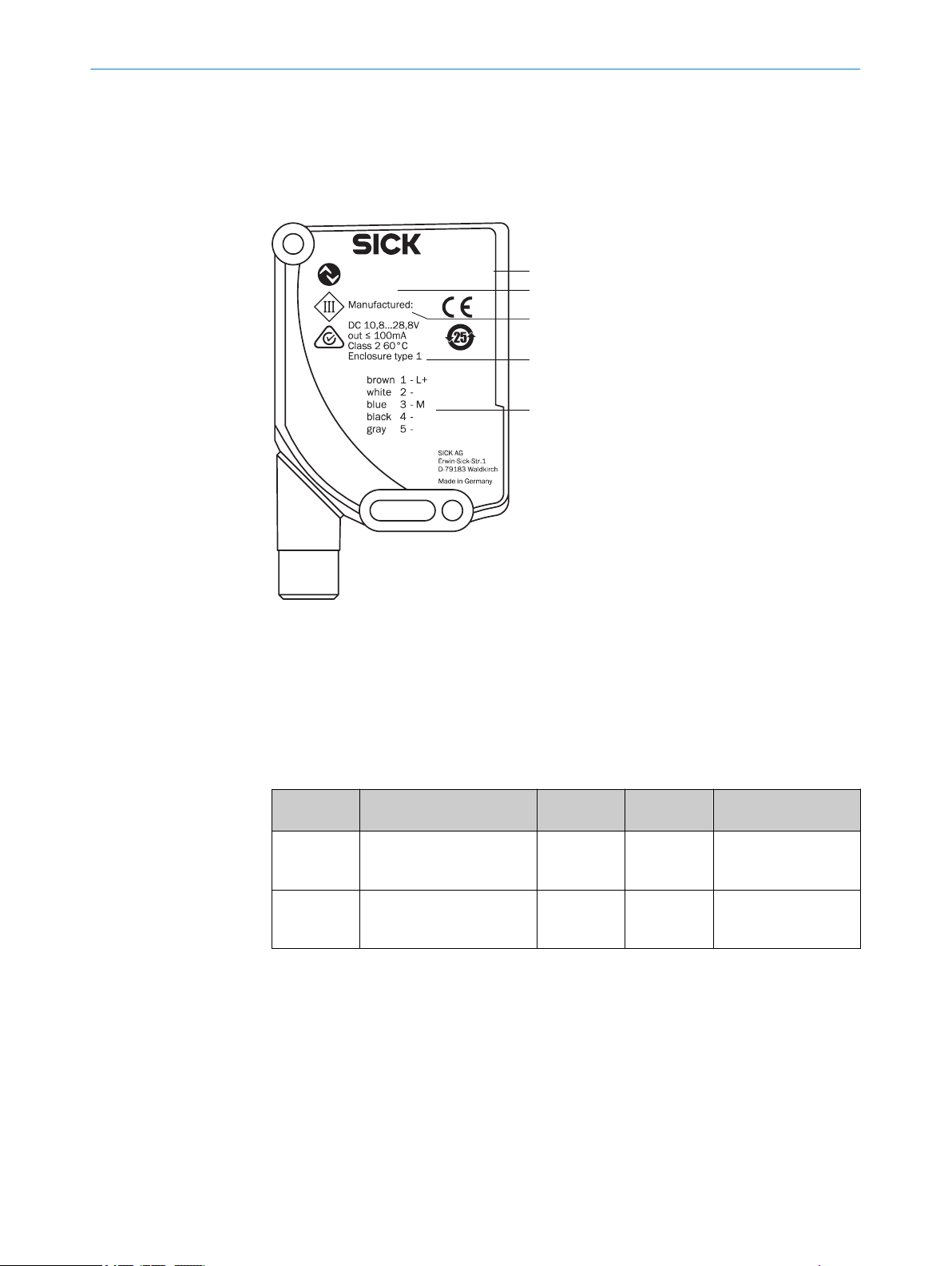
3.1 Product ID
3.1.1 Type label
3.1.2 Variants
Device type number
1
Part number
2
Date of manufacture
3
Electrical data and environmental data
4
Pin assignment
5
Table 1: Variants
Part number Type Sensing dis‐
tance
1219863 PSS-
1220058 PSS-
MBP124115AZZZZPZZZZP
ZZZZZ1
MBB124115AZZZZBZZZZP
ZZZZZ1
27.5 mm 0.8 x 8 mm Teach-in background
27.5 mm 0.8 x 8 mm Teach-in print without
Light spot Description
and print
background
10
O PE R AT I NG IN S TR U CT I ON S | PSS Prime 8022051/2018-01-31 | SICK
Subject to change without notice
Page 11

3.2 Product features and functions
SEN
E
SC
TST
TCH
SET
P
W
R
Q
1 2 3 4 5
3.2.1 Device view
Figure 1: PSS Prime light emission long housing side
Connection
1
Mounting slot
2
Display and control panel
3
Mounting hole
4
Light emission
5
PRODUCT DESCRIPTION 3
3.2.2 Product characteristics
The PSS Print Detector is primarily used in the packaging industry for verifying the pres‐
ence of prints, such as best-before dates, serial numbers, or 2D codes. They can, how‐
ever, also be used in any 1D pattern verification application.
The PSS compares a taught-in pattern with the following patterns; checks that they
match and checks for 100% correspondence to reduce deviations in contrast or length.
The sensitivity level, i.e., a print that is yet to be recognized as good quality, can be set
by the user.
10 - 30 coarse: Print is present.
•
40 - 60 medium: Print is present, but the quality is poor.
•
70 - 90 fine: Print is present, the quality is good, but details are missing.
•
Features
Sensor-based pattern recognition
•
Print pattern and background teach-in
•
Flexible, adjustable sensitivity levels
•
Response time: 10 ms
•
Trigger required
•
Print quality shown on sensor display
•
Configuration via IO-Link
•
Fields of application
Presence monitoring of prints:
Serial numbers
•
Best-before date
•
2-D code
•
Detecting good and poor print quality according to the set sensitivity level:
Degree of blackening
8022051/2018-01-31 | SICK OP E RA T IN G I N ST R UC T IO N S | PSS Prime
Subject to change without notice
•
Only partially printed
•
11
Page 12
ü
û
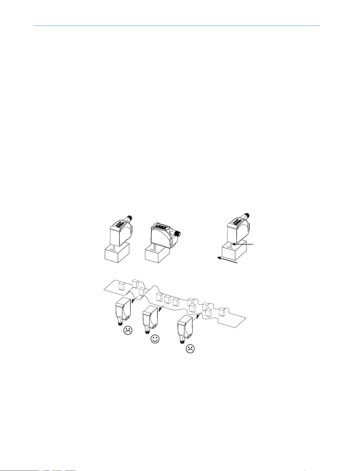
27,5 mm
MOUNTING
4
4 Mounting
4.1 Scope of delivery
PSS in the version ordered
•
Quickstart
•
Safety notes
•
4.2 Mounting requirements
Typical space requirement for the device, see type-specific dimensional drawing,
•
see "Technical data", page 31.
Comply with technical data, such as the permitted ambient conditions for opera‐
•
tion of the device (e.g., temperature range, EMC interference emissions, ground
potential).
To prevent condensation, avoid exposing the device to rapid changes in tempera‐
•
ture.
Protect the device from direct sunlight.
•
The device must only be mounted using the pairs of mounting threads/fixing holes
•
provided for this purpose.
Shock and vibration-free mounting.
•
4.3 Mounting the device
Figure 2: PSS
Figure 4: PSS - alignment
1. Install the device via the fixing hole so that the light spot enters the mark longitudi‐
nally and the test object has the least possible vertical and horizontal movement.
Note the sensing distance while doing so.
2. Compensate for the vertical and horizontal movement of the test object by marks
of suitable lengths.
3. Ensure that any device movement does not affect the sensing distance.
Figure 3: PSS - processing direction
12
O PE R AT I NG IN S TR U CT I ON S | PSS Prime 8022051/2018-01-31 | SICK
Subject to change without notice
Page 13

5 Electrical installation
5.1 Notes on the electrical installation
NOTICE
Device damage due to incorrect supply voltage!
An incorrect supply voltage may result in damage to the device.
■
Only operate the device with safety/protective extra-low voltage (SELV/PELV).
■
The sensor is a device of protection class III.
NOTICE
Device damage due to incorrect supply voltage!
An incorrect supply voltage may result in damage to the device.
Only operate the device with an LPS (limited power source) in accordance with IEC
•
60950-1 or an NEC Class 2 power supply unit.
NOTICE
Device damage or unpredictable operation due to working with live parts!
Working with live parts may result in unpredictable operation.
■
Only carry out wiring work when the power is off.
■
Only connect and disconnect electrical connections when the power is off.
ELECTRICAL INSTALLATION 5
■
The electrical installation must only be performed by electrically qualified person‐
nel.
■
Standard safety requirements must be met when working on electrical systems!
■
Only switch on the supply voltage for the device when the connection tasks have
been completed and the wiring has been thoroughly checked.
■
When using extension cables with open ends, ensure that bare wire ends do not
come into contact with each other (risk of short-circuit when supply voltage is
switched on!). Wires must be appropriately insulated from each other.
■
Wire cross-sections in the supply cable from the user’s power system must be
selected in accordance with the applicable standards.
■
Only operate the device with an LPS (limited power source) in accordance with IEC
60950-1 or an NEC Class 2 power supply unit.
■
All circuits connected to the device must be designed as SELV/PELV circuits.
■
Operation in short-circuit protected network at max. 8 A.
NOTE
Layout of data cables
■
Use screened data cables with twisted-pair wires.
■
Implement the screening design correctly and completely.
■
To avoid interference, e.g., from switching power supplies, motors, clocked drives,
and contactors, always use cables and layouts that are suitable for EMC.
■
Do not lay cables over long distances in parallel with voltage supply cables and
motor cables in cable channels.
The IP enclosure rating for the device is only achieved under the following conditions:
■
The cables plugged into the connections are screwed tight.
■
Any other covers present must be closed and lie flush on the device.
If these instructions are not complied with, the IP enclosure rating for the device is not
guaranteed!
8022051/2018-01-31 | SICK OP E RA T IN G I N ST R UC T IO N S | PSS Prime
Subject to change without notice
13
Page 14
1
2
5
4 3
5 ELECTRICAL INSTALLATION
5.2 Note on the swivel connector
NOTICE
Damage to the connector unit from over-tightening!
The connector unit on the device has two opposite end positions.
■
Do not rotate the connector unit from either of the two end positions by more than
180°.
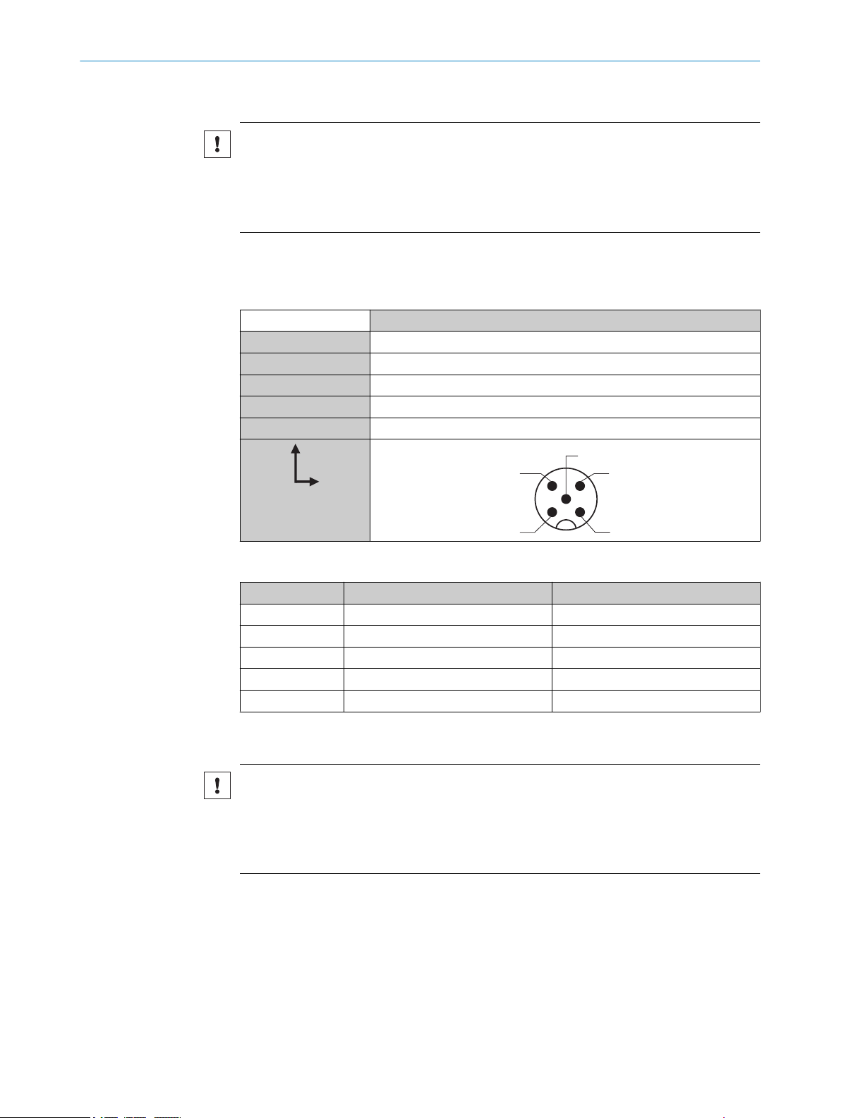
5.3 Pin assignment of the connections
Pin assignment
PSS Print Detector
1 L+
2 ET
3 M
4 Q / C
5 Trigger
IO-Link
No. Description Data type
Bit 0 Switching signal Q Boolean
Bit 1 Empty -
Bit 2 Q valid Boolean
Bit 3 - 7 Empty -
Bit 8 - 15 Quality of print Unsigned integer
5.4 Connecting the supply voltage
NOTICE
Risk of damage to the device!
The device can become damaged if it is connected to a voltage supply that is already
switched on.
Only connect the device when the supply cable is de-energized.
•
The device must be connected to a power supply unit with the following properties:
Supply voltage DC 10.8 V – 28.8 V (SELV/PELV as per currently valid standards)
•
Electricity source with at least 3 W power
•
To ensure protection against short-circuits/overload in the customer’s supply cables,
the wire cross-sections used must be appropriately selected and protected.
14
O PE R AT I NG IN S TR U CT I ON S | PSS Prime 8022051/2018-01-31 | SICK
Subject to change without notice
Page 15

5.5 Wiring the interfaces
PWRQPWR
Q
PWR
Q
+ (L+)
Q
‒ (M)
+ (L+)
Q
‒ (M)
5.5.1 Wiring the digital inputs
The digital inputs can be used to start a teach-in procedure or.
Electrical values
LOW: 0 V ≤ Ue ≤ 2 V
ELECTRICAL INSTALLATION 5
HIGH: 10 V ≤ Ue ≤ U
Input, teach-in (ET)
Push/pull: Teach = HIGH; Run = LOW
Input, Trigger
Recording = HIGH; Evaluation = LOW
5.5.2 Wiring the digital outputs
Switching behavior: push/pull
Electrical values
The sum current (100 mA) for all digital outputs is identical.
Push/pull HIGH: UV −3 V; LOW: ≤ 3 V
In the case of a push/pull sensor, the signal must be inverted in the control system in
order to obtain the same result as a sensor with NPN switching behavior.
Table 2: Push-Pull
V
Q
push-pull
(≤ 100 mA)
8022051/2018-01-31 | SICK OP E RA T IN G I N ST R UC T IO N S | PSS Prime
Subject to change without notice
15
Page 16

SEN
ESC
TST
TCH
PWR
Q
1 2 3
4
5
6
7
8
9
6 OPERATION
6 Operation
6.1 Operating elements
Table 3: Operating elements legend
No Description Function
1 PWR Illuminates when the voltage supply is connected.
2 Segment display Shows menu item, values, or qualities.
3 TCH Illuminates when the “teach-in” menu is selected.
4 SEN Illuminates when the “sensitivity” menu is selected.
5 TST Illuminates when the “test” menu is selected.
6 Plus Scrolls through menu items or increases values.
7 SET Opens the menu, confirms entries, or switches to lower-
8 Minus/ESC Switches to the previous menu item, decreases values,
9 Q Illuminates when there is a switching event.
level menus.
or cancels the current operation (press for > 3 s).
16
O PE R AT I NG IN S TR U CT I ON S | PSS Prime 8022051/2018-01-31 | SICK
Subject to change without notice
Page 17

6.2 Navigation tree, general
SET
SET
SEN
TST
TCH
PWR
Q
SEN
TST
TCH
PWR
Q
SET
SEN
TST
TCH
PWR
Q
SEn = Sensitivity
SET
SEN
TST
TCH
PWR
Q
SET
SEN
TST
TCH
PWR
Q
SET
SEN
TST
TCH
PWR
Q
Quality of Teach*
move print through light spot
tSt = Test
SET
SEN
TST
TCH
PWR
Q
SEN
TST
TCH
PWR
Q
SET
SET
SET
SEN
TST
TCH
PWR
Q
SEN
TST
TCH
PWR
Q
SET
SEN
TST
TCH
PWR
Q
SET
SEN
TST
TCH
PWR
Q
Quality of Teach*
move print through light spot
Prt = Print
move background through light spot
bcG = Background
tch = Teach
SEN
TST
TCH
PWR
Q
To leave the current menu level, press and hold the minus pushbutton for > 3 seconds.
OPERATION 6
6.3 Resetting the device (factory setting)
1. Press and hold the plus/minus pushbuttons for 10 s.
2. The set parameters are reset to the factory settings.
8022051/2018-01-31 | SICK OP E RA T IN G I N ST R UC T IO N S | PSS Prime
Subject to change without notice
17
Page 18

12345
12345
12345
OPERATION
6
6.4 Teach-in
Several teach-in processes are available for configuring the device:
Teach-in for background and print.
•
Teach-in for print without background.
•
6.4.1 Teach-in for print (background, within the trigger window, uniform/same color)
1 Start the teach-in process either by
■
Selecting the menu item “tch” on the display and confirming with Set. The
sensor now displays “prt”.
Or
■
Setting the input line “ET” to HIGH
Or
■
Sending the “Start Teach” (ISDU 2 – Value 73) system command to the sen‐
sor.
The sensor is now in teach-in mode and waits for the print to be taught in.
2 Start to teach in the print either by
■
Pressing the Set pushbutton when “Prt” is shown on the display
Or
■
Activating windowing via the trigger input line
Or
■
Sending the “Trigger window start” (ISDU 2 – Value 226) system command to
the sensor.
3 The section that is now read is taught in as a reference pattern. Move the sensor
over the print.
18
O PE R AT I NG IN S TR U CT I ON S | PSS Prime 8022051/2018-01-31 | SICK
Subject to change without notice
Page 19
12345
OPERATION
4 Depending on the type of window start, quit the teach-in process by
■
Pressing the Set pushbutton when the progress bar is shown on the display
Or
■
Deactivating windowing via the trigger input line
Or
■
Sending the “Trigger window stop” (ISDU 2 – Value 227) system command to
the sensor.
5 The teach-in process is now complete; the quality of the process (quality of teach)
is shown on the display. If the teach-in process was started via the “ET” input line,
the signal should now be reset to LOW.
6
6.4.2 Teach-in for background and print (background, within the trigger window, textured)
NOTE
– The direction of movement during teach-in must match the processing direction in
RUN mode.
– If the background changes compared with the reference pattern that was taught
in, the level of correspondence and therefore the quality of print is reduced.
1 Start the teach-in process either by
■
Selecting the menu item “tch” on the display and confirming with Set. The
sensor now displays “bck”
Or
■
Setting the input line “ET” to HIGH
Or
■
Sending the “Start Teach” (ISDU 2 – Value 71) system command to the sen‐
sor.
The sensor is now in teach-in mode and waits for the background to be
taught in. Now position the sensor in front of the background to be taught in.
2 Start to teach in the background window either by
■
Pressing the Set pushbutton when “bck” is shown on the display
Or
■
Activating windowing via the trigger input line
Or
■
Sending the “Trigger window start” (ISDU 2 – Value 226) system command to
the sensor.
8022051/2018-01-31 | SICK OP E RA T IN G I N ST R UC T IO N S | PSS Prime
Subject to change without notice
19
Page 20

12345
12345
12345
12345
OPERATION
6
3 The section that is now read is taught in as a background. Move the sensor over
the background.
4 Depending on the type of window start, quit the teach-in process by
■
Pressing the Set pushbutton when the progress bar is shown on the display
Or
■
Deactivating windowing via the trigger input line
Or
■
Sending the “Trigger window stop” (ISDU 2 – Value 227) system command to
the sensor.
The background teach-in process is now complete. The sensor waits for the
print to be taught in. Now position the sensor in front of the lettering to be
taught in.
5 Start to teach in the print either by
■
Pressing the Set pushbutton when “Prt” is shown on the display
Or
■
Activating windowing via the trigger input line
Or
■
Sending the “Trigger window start” (ISDU 2 – Value 226) system command to
the sensor.
6 The section that is now read is taught in as a reference pattern. Move the sensor
over the print.
20
O PE R AT I NG IN S TR U CT I ON S | PSS Prime 8022051/2018-01-31 | SICK
Subject to change without notice
Page 21

12345
OPERATION 6
7 Depending on the type of window start, quit the teach-in process by
■
Pressing the Set pushbutton when the progress bar is shown on the display
Or
■
Deactivating windowing via the trigger input line
Or
■
Sending the “Trigger window stop” (ISDU 2 – Value 227) system command to
the sensor.
The teach-in process is now complete; the quality of the process (quality of
teach) is shown on the display. If the teach-in process was started via the
“ET” input line, the signal should now be reset to LOW.
8022051/2018-01-31 | SICK OP E RA T IN G I N ST R UC T IO N S | PSS Prime
Subject to change without notice
21
Page 22

SET
SET
SEN
TST
TCH
PWR
Q
SEN
TST
TCH
PWR
Q
SEN
TST
TCH
PWR
Q
SET
SEN
TST
TCH
PWR
Q
tch = Teach
SEn = Sensitivity
6 OPERATION
6.5 Sensitivity
If the quality is the same or better than the set threshold, the print is recognized (Q
active 10 ms after falling edge of the trigger signal).
Table 4: Sensing distance tolerance
Sensing distance
tolerance
±2.5 mm (presence detection)
±1 mm (quality control)
10 - 30 coarse: Print is present.Presence detection
40 - 60 medium: Print is present, but the quality is poor.
70 - 90 fine: Print is present, the quality is good, but details are missing.
22
O PE R AT I NG IN S TR U CT I ON S | PSS Prime 8022051/2018-01-31 | SICK
Subject to change without notice
Page 23
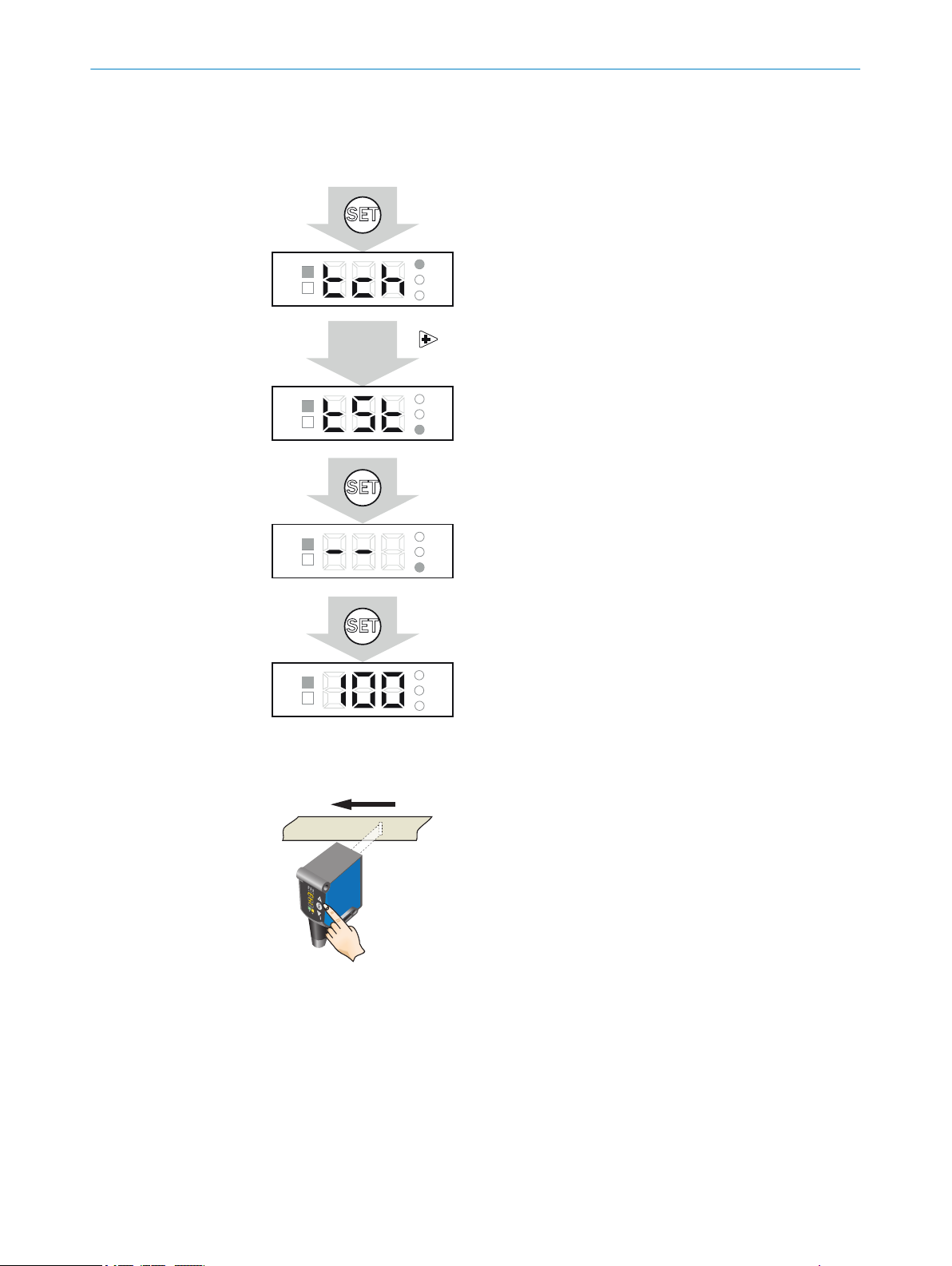
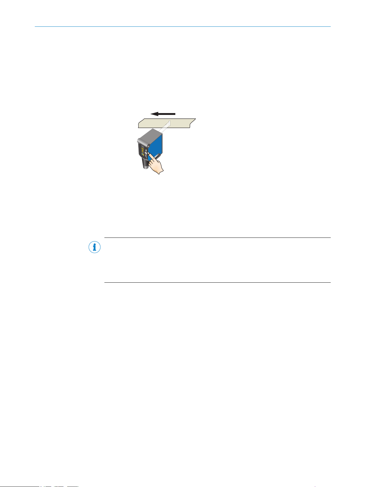
6.6 Test
SET
SEN
TST
TCH
PWR
Q
SEN
TST
TCH
PWR
Q
SET
SEN
TST
TCH
PWR
Q
SET
SEN
TST
TCH
PWR
Q
Quality of Print*
move print through light spot
tSt = Test
tch = Teach
2x
12345
12345
OPERATION 6
Test mode for the offline thorough check of the taught-in print (trigger is activated man‐
ually via the control panel).
8022051/2018-01-31 | SICK OP E RA T IN G I N ST R UC T IO N S | PSS Prime
Subject to change without notice
23
Page 24

10 ms 10 ms
10 ms
Trigger
Q PSS
10 ms10 ms10 ms
Trigger
ET
6 OPERATION
6.7 Trigger
Figure 5: Trigger
For operation, the sensor needs a trigger signal regarding the length of the print to be
evaluated for signaling the reading window. This is supplied to the sensor via Pin 5. The
start of the reading window is signaled by the rising edge of the trigger signal, the con‐
trol panel cannot be operated during this time. The end is signaled by the falling edge.
The associated output state change is present no later than 10 ms after the falling
edge. The process quality (quality of print) is displayed. When checking the print on
packaging and other objects, we recommend generating the trigger signal via a photo‐
electric sensor; if continuous material is used, the signal can be generated via a control
or a contrast sensor.
6.8
External teach-in
The external teach-in and the trigger input can be synchronized for the teach-in process
as follows:
24
O PE R AT I NG IN S TR U CT I ON S | PSS Prime 8022051/2018-01-31 | SICK
Subject to change without notice
Page 25

6.9 IO-Link
Trigger
Trigger
adjusted
1
2
12345
OPERATION 6
– Switching output logic
Switching output active if print is present or switching output active if print is not
present
– Pin 2 configuration
Pin 2 = external teach-in (default) or 2nd switching output
– Keylock
On/off
– Print teach-in/background teach-in
– Sensitivity
Sensitivity level determines the point at which the switching output is active
– Job backup
Data from various print can be saved and retrieved if necessary.
– Trigger input delay and pulse length Q
The trigger input delay 1 and the pulse length 2 enable the area of the print to
be defined more precisely
8022051/2018-01-31 | SICK OP E RA T IN G I N ST R UC T IO N S | PSS Prime
Subject to change without notice
25
Page 26

SEN
TST
TCH
PWR
Q
SEN
TST
TCH
PWR
Q
SEN
TST
TCH
PWR
Q
SEN
TST
TCH
PWR
Q
6 OPERATION
6.10 Other indicators and functions
Incorrect teach-in
In the event of a teach-in failure, Err appears on the display and the Q LED and TCH LED
flash.
Control panel locked
If the device is undergoing an internal process (e.g., reading or storing parameter sets
or teaching-in via IO-Link), the control panel is locked and the device shows “bSY” on
the segment display.
Short-circuit and overcurrent detection
In the event of a short-circuit and overcurrent, Err appears on the display and the Q LED
flashes.
Live measured value (run mode)
In run mode, the device displays the quality compared to the reference print in %.
The higher the value, the better the correspondence with the taught-in print.
26
O PE R AT I NG IN S TR U CT I ON S | PSS Prime 8022051/2018-01-31 | SICK
Subject to change without notice
Page 27

7 Troubleshooting
7.1 Possible errors during commissioning
Table 5: Troubleshooting during commissioning
Display, error situation Cause Measure
“Err” flashes
•
Q LED (yellow) flashes
•
After the teach process
“Err” flashes
•
Q LED (yellow) and TCH
•
LED (yellow) flash
No signal change at the
•
switching output for
object detection
•
•
Programmed contrast or con‐
trast difference is not suffi‐
cient for stable contrast detec‐
tion.
Short-circuit message/
overcurrent message
Sensor is not connected
properly
TROUBLESHOOTING 7
Disconnect sensor from
•
the power network
Check pin assignment
•
Reconnect sensor
•
Check the current at the
•
switching output
Readjust sensor
•
Clean sensor
•
Check the application
•
conditions
Restart teach process
•
Increase contrast differ‐
•
ence
7.2
Possible errors during operation
Table 6: Troubleshooting during operation
Display, error situation Cause Measure
Busy Sensor is undergoing an inter‐
Indication of quality “0”
nal process.
Distance or angle to
•
material not consistent
Light emission (optics) is
•
dirty
Print information is so
•
low that it cannot be
captured by the sensor
Wait until the process has fin‐
ished.
Clean sensor
•
Readjust sensor
•
Check parameter settings
•
Perform teach process
•
again
8022051/2018-01-31 | SICK OP E RA T IN G I N ST R UC T IO N S | PSS Prime
Subject to change without notice
27
Page 28

8 MAINTENANCE
8 Maintenance
8.1 Maintenance
During operation, the device works maintenance-free.
Depending on the assignment location, the following preventive maintenance tasks
may be required for the device at regular intervals:
Table 7: Maintenance schedule
Maintenance work Interval Implementation
Clean housing and front screen
Check screw connections and plug
connectors
8.2 Cleaning the device
At regular intervals (e.g., weekly), check the light emission window and the housing of
the device for dirt. This is especially relevant in harsh operating environments (dust,
abrasion, damp, fingerprints, etc.). The lens of the light emission window must be kept
clean and dry during operation.
Cleaning interval depends on ambi‐
ent conditions and climate
Every 6 months Specialist
Specialist
NOTICE
Device damage due to improper cleaning!
Improper cleaning may result in device damage.
■
Only use suitable cleaning agents.
■
Never use sharp objects for cleaning.
Cleaning the light emission window
NOTICE
Damage to the light emission window!
Reduced reading performance due to scratches or streaks on the light emission win‐
dow!
Clean the light emission window only when wet.
b
Use a mild cleaning agent that does not contain powder additives. Do not use
b
aggressive cleaning agents, such as acetone, etc.
Avoid any movements that could cause scratches or abrasions on the light emis‐
b
sion window.
Only use cleaning agents suitable for the lens material.
b
NOTE
Static charge may cause dust particles to stick to the light emission window. This effect
can be avoided by using an anti-static glass cleaner in combination with the SICK lens
cloth (can be obtained from www.sick.com).
28
NOTE
If the light emission window is scratched or damaged (cracked or broken), the device
must be replaced. Contact SICK Service to arrange this.
O PE R AT I NG IN S TR U CT I ON S | PSS Prime 8022051/2018-01-31 | SICK
Subject to change without notice
Page 29

MAINTENANCE 8
Cleaning the housing
In order to ensure that the heat produced by the internal power loss is adequately dissi‐
pated, the housing surface must be kept clean.
8022051/2018-01-31 | SICK OP E RA T IN G I N ST R UC T IO N S | PSS Prime
Subject to change without notice
29
Page 30

9 DECOMMISSIONING
9 Decommissioning
9.1 Disassembly and disposal
Disassembling the device
1. Switch off the supply voltage to the device.
2. Detach all connecting cables from the device.
3. If the device is being replaced, mark its position and alignment on the bracket or
surroundings.
4. Detach the device from the bracket.
Disposing of the device
Any device which can no longer be used must be disposed of in an environmentally
friendly manner in accordance with the applicable country-specific waste disposal regu‐
lations. As it is categorized as electronic waste, the device must never be disposed of
with household waste!
9.2 Returning devices
Do not dispatch devices to the SICK Service department without consultation.
b
NOTE
To enable efficient processing and allow us to determine the cause quickly, please
include the following when making a return:
■
Details of the contact person
■
Description of the application
■
Description of the fault that occurred
30
O PE R AT I NG IN S TR U CT I ON S | PSS Prime 8022051/2018-01-31 | SICK
Subject to change without notice
Page 31

10 Technical data
Ø 4,1
62
43,3
9
5,5
32
53,6
4,2
47,5
2
3
26
15
1
4
10.1 General data
Table 8: Technical data
Attribute Value
Sensing distance 27.5 mm
Sensing distance tolerance ±2.5 mm (presence monitoring)
Light spot size/light spot direction 0.8 mm x 8 mm
Supply voltage
Switching type Push/pull
Switching output (Q) Switching output active after falling edge of the trigger
Input, teach-in (ET) Teach: U = 10 V … < U
Input, trigger current consumption: U = 10 V … < U
Enclosure rating IP67
Ambient temperature (operation) -20 C …+60 °C
Ambient temperature (storage) -25 °C … +75 °C
Protection class III
Circuit protection UV connections, reverse polarity protected, output Q
Max. output current of the switching
output
1
Operation in short-circuit protected network max. 8 A
2
Sum current of all digital outputs
TECHNICAL DATA 10
±1 mm (quality control)
1
10.8 V – 28.8 V
signal: max. 10 ms
V
Run: U < 2 V
V
Evaluation: U < 2 V
short-circuit protected, interference-pulse suppression
100 mA
2
10.2 Dimensional drawings
1
2
3
4
Optical axis, sender
Fixing hole
M12 male connector (can be rotated by 180°)
Control panel
8022051/2018-01-31 | SICK OP E RA T IN G I N ST R UC T IO N S | PSS Prime
Subject to change without notice
31
Page 32

11 ACCESSORIES
11 Accessories
NOTE
Accessories can be found on the online product page at:
b
www.sick.com/PSS
32
O PE R AT I NG IN S TR U CT I ON S | PSS Prime 8022051/2018-01-31 | SICK
Subject to change without notice
Page 33

12 Annex
12.1 EU declaration of conformity and certificates
The EU declaration of conformity and other certificates can be downloaded from the
Internet at:
www.sick.com/PSS
b
12.2 Certification according to UL 60947-5-2
The PSS Prime Print Detector is certified in accordance with UL 60947-5-2 if they are
supplied with power by LPS or Class 2 power supply units.
ANNEX 12
The certification is only valid with corresponding device identification on the type label
of the respective device.
8022051/2018-01-31 | SICK OP E RA T IN G I N ST R UC T IO N S | PSS Prime
Subject to change without notice
33
Page 34

Further locations at www.sick.com
Australia
Phone +61 3 9457 0600
1800 334 802 – tollfree
E-Mail sales@sick.com.au
Austria
Phone +43 22 36 62 28 8-0
E-Mail office@sick.at
Belgium/Luxembourg
Phone +32 2 466 55 66
E-Mail info@sick.be
Brazil
Phone +55 11 3215-4900
E-Mail marketing@sick.com.br
Canada
Phone +1 905 771 14 44
E-Mail information@sick.com
Czech Republic
Phone +420 2 57 91 18 50
E-Mail sick@sick.cz
Chile
Phone +56 2 2274 7430
E-Mail info@schadler.com
China
Phone +86 20 2882 3600
E-Mail info.china@sick.net.cn
Denmark
Phone +45 45 82 64 00
E-Mail sick@sick.dk
Finland
Phone +358-9-2515 800
E-Mail sick@sick.fi
France
Phone +33 1 64 62 35 00
E-Mail info@sick.fr
Germany
Phone +49 211 5301-301
E-Mail info@sick.de
Hong Kong
Phone +852 2153 6300
E-Mail ghk@sick.com.hk
Hungary
Phone +36 1 371 2680
E-Mail office@sick.hu
India
Phone +91 22 6119 8900
E-Mail info@sick-india.com
Israel
Phone +972 4 6881000
E-Mail info@sick-sensors.com
Italy
Phone +39 02 274341
E-Mail info@sick.it
Japan
Phone +81 3 5309 2112
E-Mail support@sick.jp
Malaysia
Phone +6 03 8080 7425
E-Mail enquiry.my@sick.com
Mexico
Phone +52 (472) 748 9451
E-Mail mario.garcia@sick.com
Netherlands
Phone +31 30 2044 000
E-Mail info@sick.nl
New Zealand
Phone +64 9 415 0459
0800 222 278 – tollfree
E-Mail sales@sick.co.nz
Norway
Phone +47 67 81 50 00
E-Mail sick@sick.no
Poland
Phone +48 22 539 41 00
E-Mail info@sick.pl
Romania
Phone +40 356 171 120
E-Mail office@sick.ro
Russia
Phone +7 495 775 05 30
E-Mail info@sick.ru
Singapore
Phone +65 6744 3732
E-Mail sales.gsg@sick.com
Slovakia
Phone +421 482 901201
E-Mail mail@sick-sk.sk
Slovenia
Phone +386 591 788 49
E-Mail office@sick.si
South Africa
Phone +27 11 472 3733
E-Mail info@sickautomation.co.za
South Korea
Phone +82 2 786 6321
E-Mail info@sickkorea.net
Spain
Phone +34 93 480 31 00
E-Mail info@sick.es
Sweden
Phone +46 10 110 10 00
E-Mail info@sick.se
Switzerland
Phone +41 41 619 29 39
E-Mail contact@sick.ch
Taiwan
Phone +886 2 2375-6288
E-Mail sales@sick.com.tw
Thailand
Phone +66 2645 0009
E-Mail Ronnie.Lim@sick.com
Turkey
Phone +90 216 528 50 00
E-Mail info@sick.com.tr
United Arab Emirates
Phone +971 4 88 65 878
E-Mail info@sick.ae
United Kingdom
Phone +44 1727 831121
E-Mail info@sick.co.uk
USA
Phone +1 800 325 7425
E-Mail info@sick.com
Vietnam
Phone +84 945452999
E-Mail Ngo.Duy.Linh@sick.com
8022051/2018-01-31/en
SICK AG | Waldkirch | Germany | www.sick.com
 Loading...